Electro-mechanical Response of Elastomer Membranes Coated With Ultra-thin Metal Elecgtrodes

NONLINEAR SHELL MODELING OF THIN MEMBRANES WITH EMPHASIS ON STRUCTURAL WRINKLING
Alexander Tessler*, David W. Sleight*, and John T. Wang*
Analytical and Computational Methods Branch, Structures and Materials Competency NASA Langley Research Center, Hampton, VA 23681-2199, U.S.A.
Abstract
Thin solar sail membranes of very large span are being envisioned for near-term space missions. One major design issue that is inherent to these very flexible structures is the formation of wrinkling patterns. Structural wrinkles may deteriorate a solar sail’s performance and, in certain cases, structural integrity. In this paper, a geometrically nonlinear, updated Lagrangian shell formulation is employed using the ABAQUS finite element code to simulate the formation of wrinkled deformations in thin-film membranes. The restrictive assumptions of true membranes, i.e. Tension Field theory (TF), are not invoked. Two effective modeling strategies are introduced to facilitate convergent solutions of wrinkled equilibrium states. Several numerical studies are carried out, and the results are compared with recent experimental data. Good agreement is observed between the numerical simulations and experimental data.
Introduction The exploitation of solar energy for the purpose of
near-term space exploration presents a viable and attractive possibility in the minds of NASA scientists and engineers. The specific propulsion technology is called solar sails. Very large, ultra-low-mass, thin-polymer film (gossamer) structures are now being designed and tested for a wide variety of space exploration missions. The difficulties associated with conducting tests in a weightless environment place greater emphasis on the reliance on computational methods. Other gossamer structures that possess similar structural characteristics include inflatable space antennas, sun shields, and radars. A concise overview of gossamer structures and related technologies can be found, for example, in [1].
A solar sail can gain momentum from incidence of sunlight photons at its surface. Since the momentum carried by an individual photon is very small, the solar sail must have a large surface area and a low mass, so that sufficient acceleration can be generated. Also, a solar sail requires a highly reflective surface that has minimal wrinkling and billowing under operational conditions. In the presence of significant wrinkling and billowing, the solar sail may lose efficiency, as compared to a flat sail, due to the oblique incidence of photons. The billowing problem may be overcome by applying sufficient tension to the sail membrane. Higher tensile stresses, however, are commonly
accompanied by greater amplitude and longer structural wrinkles.
A thin-film solar sail is a classical two-dimensional structure, with a thickness that is much smaller than its lateral dimensions. Since the bending stiffness is negligibly small compared to its membrane stiffness, the load-carrying capability using thin, low-modulus films is predominantly due to tensile membrane stresses. One key response phenomenon intrinsic to this class of structures is structural wrinkling. Structural wrinkles are local post-buckling patterns that are manifested by geometrically large transverse deformations whose magnitudes are much larger than the membrane thickness. Their formation is generally attributed to extremely low compressive stresses supported by extremely low bending stiffness. To simulate such effects, the analytical model must necessarily account for both membrane and bending deformations undergoing geometrically nonlinear kinematics with large displacements and rotations, i.e., a geometrically nonlinear shell model. However, obtaining stable equilibrium states using shell-based modeling turns out to be a challenging computational problem. Here, the elastic deformations, possessing a very small amount of strain energy, are accompanied by large rigid-body motions, rendering these structures under constrained. Moreover, the shell models for these problems are highly ill-conditioned. The membrane rigidity, being much greater than the bending rigidity, may dominate excessively, thus suppressing the formation of wrinkling deformations.
Because of the aforementioned analytical and computational challenges, most investigations of the analysis of thin membranes excluded the bending effect altogether, resulting in Tension Field (TF) theory applicable to the so-called true membranes [2-16]. By eliminating compressive stresses through a modification of the constitutive relations, TF theory enables the prediction of the basic load transfer and wrinkle orientations in membranes; however, it cannot predict the out-of-plane wrinkled shapes, wavelengths, and amplitudes. Stein and Hedgepeth [6] explored a modified version of TF theory by identifying partially wrinkled domains. Following their methodology, Miller and Hedgepeth [10] performed a finite element analysis using a recursive stiffness-modification procedure termed the Iterative Membrane Properties (IMP) method. Several computational efforts [11-16] employed the IMP and penalty-based formulations of
* Aerospace Engineer, Member AIAA. 1
American Institute of Aeronautics and Astronautics
https://ntrs.nasa.gov/search.jsp?R=20030064950 2018-06-05T18:02:36+00:00Z

TF theory by implementing appropriate routines into the nonlinear finite element codes TENSION6 [17,18] and ABAQUS [19]. The main utility of these TF approaches is to enable adequate load-carrying predictions to be made and to enable the general regions where structural wrinkles develop to be identified. The major shortcoming of the TF schemes, however, is their inability to predict the wavelengths and amplitudes of wrinkles. This shortcoming may be overcome by modeling thin-film structures using shell-based finite element analysis that includes both membrane and bending deformations.
Recent advances in nonlinear computational methods and shell-element technology offered viable possibilities of simulating highly nonlinear wrinkled deformations in thin membranes using shell-based analysis. Lee and Lee [20] developed a nine-node, quadratic shell element that used artificially modified shear and elastic moduli to enable locking-free shell analysis of very thin shells. They also employed small out-of-plane geometric imperfections using trigonometric functions. In addition, a fictitious damping term was added to the nonlinear equilibrium equations to circumvent numerical ill-conditioning due to stability issues. They computed a wrinkled deformation state for a square membrane subjected two tensile forces; however, the numerical results were not validated with experiment. A similar computational effort using ABAQUS [19], by Wong and Pellegrino [21], involved the use of superposition of buckling eigenvectors to describe small out-of-plane geometric imperfections over the entire spatial domain of a membrane. They also provided some comparisons with experimental results. Neither of these efforts, however, examined how the application of various types of geometric imperfections and their spatial distributions may affect the outcome of a nonlinear analysis.
In this paper, several modeling ideas are explored for the purpose of aiding the geometrically nonlinear, updated Lagrangian shell analysis of thin-film membranes with emphasis on the wrinkled equilibrium/deformation state. The modeling ideas include (1) a simplified and computationally efficient way of introducing out-of-plane geometric imperfections, thus ensuring the necessary coupling between the membrane and bending deformations, and (2) identifying the tension-loaded corner regions as the critical modeling areas. Unless adequate meshing and load introduction are used, these regions can effectively “lock” the wrinkling formation due to an overly stiff behavior. The undesirable stiffening may also be directly linked to the boundary restraints in the corner regions, thus preventing the formation of wrinkles.
Several numerical studies are carried out using the ABAQUS code. These studies include analyses of (1) a flat rectangular membrane loaded in shear, and (2) a flat
square membrane loaded in tension by corner forces. Relevant parametric studies of geometric imperfections are performed and provide an improved insight on their use in the geometrically nonlinear analysis of thin membranes. Comparisons with experimental results are also provided and discussed.
Analysis Framework and Modeling Strategies Elastic, quasi-static shell analyses and parametric
studies of thin-film membranes loaded in plane are carried out using the Geometrically Non-Linear (GNL), updated Lagrangian description of equilibrium formulation implemented in ABAQUS [19].
The selection of a four-node, shear-deformable shell element, S4R5, incorporating large-displacement and small-strain assumptions, is made because of the following considerations. The element is based upon Mindlin theory and uses C0-continuous bilinear kinematics. To allow adequate modeling of thin-shell bending, the element employs reduced integration of the transverse shear energy and an ad hoc correction factor that multiplies the transverse shear stiffness. The latter device imposes the Kirchhoff constraints (i.e., zero transverse shear strains) numerically. Both of these “computational remedies” are intended to facilitate locking-free bending deformations in thin shells. To improve the element’s reliability, an hourglass control method is used to suppress spurious zero-energy (hourglass) modes that result from under-integrating the shear strain energy. Such low-order, C0-continuous shell elements are commonly preferred for nonlinear analysis because of their computational efficiency, robustness, and superior convergence characteristics.
For a localized structural instability such as wrinkling, the ABAQUS code provides a volume-proportional numerical damping scheme invoked by the STABILIZE parameter. The stabilization feature adds fictitious viscous forces to the global equilibrium equations. This enables the computation of finite displacement increments in the vicinity of unstable equilibrium and thus circumvents numerical ill-conditioning due to stability issues. The default value of the stabilization parameter (2.0×10⁻⁴) is used in the numerical examples that follow.
Next, quasi-static shell solutions for two thin-film membranes are discussed. The deformations in these membranes are associated with the highly nonlinear, low-strain-energy equilibrium states that possess structural wrinkles. Enabling modeling strategies for the solution of these computationally challenging problems are discussed.
Application of Pseudorandom Geometric Imperfections
When planar membranes are subjected to purely in-plane loading, no mechanism exists, even in the
American Institute of Aeronautics and Astronautics
2

presence of compressive stresses, to initiate the out-of-plane, buckled deformations. One way to overcome this difficulty is to perturb slightly the planar geometry out of plane. In this manner, the geometric perturbations (imperfections) will engender the necessary coupling between the bending and membrane deformations.
In this effort, to initiate the requisite membrane-to-bending coupling, pseudorandom geometric imperfections are imposed at the nodes of the originally planar membrane mesh. The computing effort involved in generating such a set of pseudorandom numbers is trivial. In the simplest setting, the imperfections can be applied at every interior node of the mesh, and the imperfection magnitudes may be computed as a function of the membrane thickness as
) ,1( Nihz ii =δα= (1)
where is a dimensionless amplitude parameter, α1,1[−∈i ]δ is a pseudorandom number, h is the
membrane thickness, and N is the number of nodes with the imposed imperfections. As will be subsequently demonstrated, there are many alternative ways of spatially distributing these imperfections and choosing the value of . α
The imperfection amplitudes, , that are regulated by , need to be sufficiently small in relation to the element size to avoid excessive out-of-plane element distortions; this is particularly significant for planar elements with four or more nodes. To preserve a nearly flat membrane, may need to be small in comparison to the membrane thickness. However, should be large enough to enable adequate coupling to take place between membrane and bending deformations. This aspect is quantified in a parametric study that follows.
izα
iziz
The randomness aspect of Eq. (1) ensures an unbiased imperfection pattern. Thus the imperfections neither predefine nor dominate the resulting deformed equilibrium state. Geometric imperfections are commonly specified over the whole spatial domain of a membrane, e.g., as in [20,21]. As demonstrated subsequently, strategic application of geometric imperfections over partial mesh regions may also be just as effective. This further points out that conducting a computationally intensive analysis to generate geometric imperfections based on a related structural problem, such as a buckling eigenvalue problem in [21], may be entirely unnecessary. Square Thin-Film Membrane Subjected to In-plane Shear Loading
The choice of the first numerical example is primarily motivated by the availability of recent experimental data obtained by Prof. Jack Leifer and his colleagues at NASA Langley using the photogrammetry technique (refer to Leifer et al. [22]). The problem is closely analogous to that reported in [21]. The material
data, geometry, and loading are shown in Figure 1, where a square membrane (Mylar® polyester film, edge length, a=229 mm) is clamped along the bottom edge and subjected to a uniform horizontal displacement of 1 mm along the top edge. The span-to-thickness ratio (a/h) of the membrane is approximately 3×10³ and, from the perspective of shell theory, is regarded as a thin shell. Based upon results of a preliminary convergence study (not discussed herein), a highly refined mesh is constructed of 104 square-shaped S4R5 shell elements. The numerical model that is originally planar is augmented by the pseudorandom, nodal imperfections distributed over the interior nodes of the model, using the amplitude parameter 1.0=α . In Figure 2, the out-of-plane deformation contours are depicted showing a relatively close agreement between the experiment and analysis in terms of the number of wrinkles, their orientation and amplitudes. The amplitude of the left-edge wrinkle deflecting downward, which represents the maximum wrinkle amplitude, compares within 5% between the experiment and analysis. It should be noted, however, that in the experiment, the Mylar film was slightly curved out-of-plane before the application of the horizontal displacement. This actual initial imperfection was not included in the computational model given that the main focus of this analysis was to validate the efficacy of the pseudorandom imperfection approach. Naturally, provided that the actual initial imperfections are adequately measured prior to loading, they should be included in a computational model.
Square Thin-Film Membrane Subjected to Symmetric Corner Tensile Loads
When a tensile load is applied at a corner of a thin-film membrane, wrinkles tend to radiate from the corner; subsequently, the corner wrinkling affects the wrinkled equilibrium state over the entire membrane domain.
Recently, Blandino et al. [23] performed a laboratory test on a 500 mm square, flat membrane made of a KAPTON® Type HN film. The material properties, membrane dimensions, and loading are shown in Figure 3. The membrane is subjected to tensile corner loads (F=2.45 N) applied in the diagonal directions via Kevlar threads at the left and bottom corners of the membrane. The top and right corners of the membrane are fixed to the test frame with Kevlar threads. The corners are also reinforced on both sides with small patches of a transparency film (approximately 10 mm in diameter).
A suitable analytical model, that is statically equivalent to the experimental one, would result in the loading by four tension corner forces acting in the opposite directions along the two diagonals of the square membrane. In a computational shell model,
American Institute of Aeronautics and Astronautics
3

specifying the applied concentrated forces at the corner nodes does not lead to a wrinkled equilibrium state, even with the inclusion of the geometric imperfections discussed in the previous example. Here, two model-related pitfalls that prevent the development of wrinkling can be inferred. First, a concentrated corner force, causing a near-singular membrane stress field, may bring about pathological performance in the neighboring elements, since conventional elements cannot model singular stress fields. Thus the dominant membrane strain energy may suppress an already very small bending energy, causing severe ill-conditioning and eliminating the influence of the local bending energy altogether. The second modeling concern is of kinematical nature. The corner elements are often distorted, meeting at a single corner node (i.e., quadrilaterals collapsed into triangles) at which kinematic boundary conditions may be imposed. Tessler [24] demonstrated, in closed form and numerically, that acute bending stiffening (and even “shear locking”) may result in otherwise perfectly well performing Mindlin elements strictly due to over constraining of the element kinematics because of the nodal restraints. This severe bending stiffening results from the Kirchhoff constraints (zero transverse shear strain conditions) that engender spurious kinematic relations in the elements situated along the boundaries (and lines of symmetry) where the kinematic restraints are imposed. Consequently, with the over constrained, stiff corners, no wrinkling can be initiated.
The above arguments lead to a basic conclusion that eliminating sharp-corner meshes, in the regions where concentrated loads are applied, may be beneficial for the modeling of wrinkled equilibrium states. Truncating a corner a short distance inward may result in an improved load transfer and mesh quality in that local region. This truncation will necessitate replacing the concentrated force with a statically equivalent distributed traction. The benefits of this strategy are twofold: (a) removal of a severe stress concentration (note that in practice, the load introduction into a structure is closer to a distributed load than a concentrated force), and (b) improvements in the kinematics in the critical corner regions from which wrinkles radiate.
Consistent with the present modeling philosophy, the corners of the square membrane are “cut-off” such that the length of each corner edge (which is normal to the direction of the applied load) is set to be small, as shown in Figure 4. The prescribed kinematic boundary restraints are also depicted in the figure. The domain of the entire membrane is discretized with a relatively refined mesh (4,720 elements) for the purpose of a suitable comparison with the experiment. For simplicity and for the purpose of validating the efficacy the corner cut-off modeling, the reinforced corners of the
membrane are not modeled. (It is expected, however, that including the corner reinforcements in a computational model would result in improved correlation with the experiment.) The originally planar finite element mesh is augmented by the pseudorandom, nodal imperfections distributed over the interior nodes of the model, using the amplitude parameter 1.0=α (A parametric study on the selection of α is discussed subsequently.)
The contour plots depicting the deflection distributions in the experiment and the present geometrically nonlinear shell analysis are shown in Figure 5. The computer simulation is able to effectively predict four wrinkles radiating from the truncated corner regions just as those from the measured experimental results. The analysis also shows that curling occurs at the free edges as observed in the experimental results; however, the amplitudes of the experimental deflections are somewhat greater. Although intended to be symmetric, the experimental results are somewhat asymmetric. As in the previous example, the actual initial geometric imperfections, not incorporated in the analysis, may have contributed to a significant asymmetry in the experiment and the differences with the analysis. This again is evidence to the fact that such ultra-flexible and lightly stressed spatial structures are not only difficult to model analytically but also to test experimentally, requiring further refinements in the experimental methods for these thin-film membranes. 1. A study of imperfection amplitudes
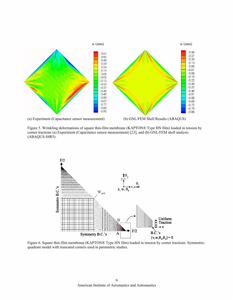
The practical question of how to decide on the appropriate value of the amplitude parameter, α , in Eq. (1) may be satisfactorily answered through a parametric study in which the distribution of the pseudorandom imperfections is kept constant, and the value of α is varied. To minimize the computational effort, it suffices to model a symmetric quadrant of the membrane as shown in Figure 6, where the imperfections are defined over all interior nodes. The appropriate truncations of the corners, the application of statically equivalent distributed tractions, and the symmetry boundary conditions are all implemented as previously described.
The amplitude parameter, , is varied in the range α0.5001.0 ≤α≤ , and for each fixed value of this
parameter, a geometrically nonlinear analysis is performed. The results from this study are presented in Figure 7, where a normalized deflection, Wmid/h, at the center of the membrane free edge (and which represents the maximum value of the deflection across the entire domain), is plotted versus . There are three basic ranges in the graph. For very small amplitudes (
α
005.0<α ), the imperfections are not large enough to provide sufficient bending-to-membrane coupling. No wrinkling deformations can be simulated. In the range
American Institute of Aeronautics and Astronautics
4

0.101.0 ≤α≤ , all analyses predict practically the same wrinkled deformation equilibrium state as evidenced by the constant value of Wmid/h across this range of α. The solutions corresponding to the values can be viewed as erroneous because this range of
1>αα values
implies that the imperfection amplitudes are too large; in fact, they are on the order of the membrane thickness. One way to interpret this is by examining the transverse element distortions that may have been caused by the large imperfections: in general, one of the four element nodes will be out of plane, thus violating the basic element formulation. 2. A study of spatial distribution of imperfections
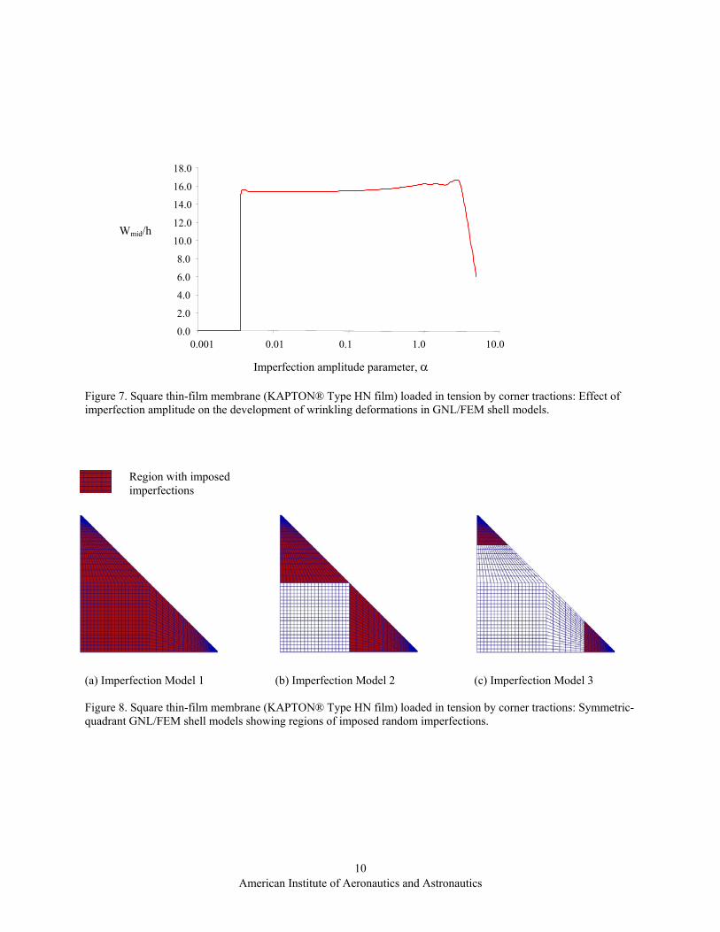
In this study, several alternative schemes of spatial distributions of the imperfections are examined in relation to their effect on the wrinkled equilibrium states. Consider three distinct imperfection distribution models corresponding to α = 0.10 (from the acceptable range of values), as shown in Figure 8. In Model 1, the imperfections are imposed across all of the interior nodes (in the shaded region). In Models 2 and 3, the imperfections are only focused on the corner regions. The results from this study are presented in Figure 9, which shows a wrinkled wave along the A-B line (see Figure 6). Noticeably, the three imperfection schemes produce the same wrinkled deformations, and this is consistent across the whole membrane. Thus the imperfection schemes may be deemed equivalent from the perspective of determining the appropriate wrinkled deformations for this problem. This is not surprising since the dominant wrinkling modes emanate from the corner regions. For this reason, the imperfections need only be imposed over these key regions.
Concluding Remarks In this paper, careful modeling considerations were
explored to simulate the formation of highly nonlinear wrinkling deformations in thin-film membranes. The analyses were carried out within the framework of the geometrically nonlinear, updated Lagrangian shell formulation using a commercial finite element code ABAQUS. The underlying shell relations employ the assumptions of small strains, large displacements, and do not rely on the classical membrane assumptions of Tension Field theory. The finite element models utilize a Mindlin-type quadrilateral shell element, S4R5. The element employs reduced integration of the transverse shear energy, and has an ad hoc correction factor multiplying the shear stiffness to ensure locking-free bending behavior even for very thin shells. Moreover, the hourglass control scheme is used to suppress spurious zero-energy (hourglass) modes that result as a consequence of the reduced integration.
To achieve convergent geometrically nonlinear solutions that correlate well with experiment, the issue
of deformation coupling between bending and membrane deformation was addressed. By applying pseudorandom out-of-plane imperfections to the initially planar membrane surface, the requisite membrane-to-bending coupling is invoked at the commencing stage of the nonlinear solution process. Using relatively small and unbiased imperfections, converged wrinkled equilibrium states can be obtained which are independent of the initial imperfections.
For the class of thin-film problems in which corner regions are subjected to tension loads, as in the second example problem, the need for improved modeling of such corner regions was identified. The introduction of truncated corners and the replacement of concentrated loads with statically equivalent distributed tractions enabled successful geometrically nonlinear wrinkled stress states to be determined.
The present modeling schemes were used in several numerical studies involving thin-film membranes subjected to mechanical loads. First, converged wrinkled deformation modes were predicted for a square membrane loaded in shear. These results compared favorably with an experiment recently conducted at NASA Langley. In the second example, a square membrane subjected to four-corner tensile loads was analyzed and exhibited major wrinkling emanating from the corners. The corner regions were truncated in the model in order to “design out” the near singular stress fields associated with concentrated loads and to improve element topology to avoid overly stiff corners. A noticeably close correlation with the experiment was also observed for this very challenging computational problem. It is expected that even closer correlation may be possible once the corner reinforcements are represented in a computational model in sufficient detail. Also, a greater insight was developed through a set of parametric studies of the amplitudes and spatial distributions of the pseudorandom imperfections.
Our experience with the geometrically nonlinear, updated Lagrangian shell analysis of thin-film membranes suggests that the current state-of-the-art computational methods have the potential for adequately simulating the structural response of such highly flexible and under constrained wrinkled structures. There exist, however, numerous challenging issues requiring in-depth analytic, computational, and experimental pursuits. Issues related to robustness, nonlinear solution convergence, sensitivity to boundary restraints and applied loading, mesh dependence, and the shell-element technology, specifically addressing ultra-thin behavior, need to be closely examined and addressed. Computational opportunities also exist in exploring the explicit dynamics nonlinear analyses that may have the advantage of obviating the stability issues in modeling the wrinkling phenomenon.
American Institute of Aeronautics and Astronautics
5
Acknowledgements The authors would like to thank Profs. Jack Leifer,
University of Kentucky, and Joe Blandino, James Madison University, for providing the experimental results.
References 1. Chmielewski, A. B., “Overview of Gossamer
Structures,” Chapter 1 in Gossamer Spacecraft: Membrane and Inflatable Structures Technology for Space Applications (ed. C. H. M. Jenkins), Vol. 191, Progress in Astronautics and Aeronautics, AIAA, 1-33, 2001.
2. Wagner, H., “Flat Sheet Metal Girders with Very Thin Metal Web,” Z. Flugtechnik Motorluftschiffahrt, Vol. 20, 200-314, 1929.
3. Reissner, E., “On Tension Field Theory.” Proceedings of the 5th Int’l Congr. Appl. Mech., 88–92, 1938.
4. Kondo, K., Iai, T., Moriguti, S., and Murasaki, T., “Tension-Field Theory,” Memoirs of the Unifying Study of Basic Problems In Engineering Science by Means of Geometry, Vol. 1, Gakujutsu, Bunken Fukyo-Kai, Tokyo, 61-85, 1955.
5. Mansfield, E. H., “Load Transfer via a Wrinkled Membrane,” Proceedings of the Royal Society of London, Vol. 316, 269-289, 1970.
6. Stein, M., and Hedgepeth, J. M., “Analysis of Partly Wrinkled Membranes,” NASA TN D-813, 1961.
7. Wu, C. H, and Canfield, T. R., “Wrinkling in Finite Plane Stress Theory,” Q. Appl. Math., Vol. 39, 179-199, 1981.
8. Pipkin, A. C., “The Relaxed Energy Density for Isotropic Elastic Membranes,” IMA J. Applied Mathematics, Vol. 36, 85-99, 1986.
9. Steigmann, D. J., and Pipkin, A. C., “Wrinkling of Pressurized Membranes,” ASME Journal of Applied Mechanics, Vol. 56, 624-628, 1989.
10. Miller, R. K. and Hedgepeth, J. M., “An Algorithm for Finite Element Analysis of Partly Wrinkled Membranes,” AIAA, 20,1761–1763, 1982.
11. Adler, A. L., Mikulas, M. M., and Hedgepeth, J. M, “Static and Dynamic Analysis of Partially Wrinkled Membrane Structures,” 41st AIAA/ASME/ASCE/AHS/ASC Structures, Structures Dynamics, and Material Conference, Atlanta, GA, AIAA-2000-1810, April 2000.
12. Schur, W. W., “Tension-field Modeling by Penalty Parameter Modified Constitutive Law,” Proceedings of the 24th Midwestern Mechanics Conf., Ames, IA, 1995.
13. Liu, X., Jenkins, C. H., Schur, W. W., “Large Deflection Analysis of Pneumatic Envelopes Using a Penalty Parameter Modified Material Model,”
Finite Elements in Analysis and Design, Vol. 37, 233-251, 2001.
14. Liu, X., Jenkins, C. H., and Schur, W. W., “Fine Scale Analysis of Wrinkled Membranes,” Int. J. Computational Eng. Sci. Vol. 1, 281-298, 2000.
15. Blandino, J. R., Johnston, J. D., Miles, J. J., and Dharamsi, U. K., “The Effect of Asymmetric Mechanical and Thermal Loading on Membrane Wrinkling,” 43rd AIAA/ASME/ASCE/AHS Structures, Structural Dynamics, and Materials Conference, Denver, CO, AIAA-2002-1371, April 2002.
16. Johnston, J. D., “Finite Element Analysis of Wrinkled Membrane Structures for Sunshield Applications,” 43rd AIAA/ASME/ASCE/AHS Structures, Structural Dynamics, and Materials Conference, Denver, CO, AIAA-2002-1456, April 2002.
17. Lo, A., “Nonlinear Dynamic Analysis of Cable and Membrane Structures.” Ph.D. Dissertation, Oregon State University, Corvalis, 1981.
18. Jenkins, C. H. and Leonard, J. W., “Dynamic Wrinkling Of Viscoelastic Membranes," J Appl Mech, 60, 575-582, 1993.
19. ABAQUS/Standard User’s Manual, Version 6.3.1, Hibbitt, Karlsson, and Sorensen, Inc., Pawtucket, RI, 2002.
20. Lee, K., and Lee, S. W., “Analysis of Gossamer Space Structures Using Assumed Strain Formulation Solid Shell Elements,” 43rd AIAA/ASME/ASCE/AHS/ASC Structures, Structures Dynamics, and Material Conference, Denver, CO, AIAA-2002-1559, April 2002.
21. Wong, Y. W., and Pellegrino, S., “Computation of Wrinkle Amplitudes in Thin Membranes,” 43rd AIAA/ASME/ASCE/AHS/ASC Structures, Structures Dynamics, and Material Conference, Denver, CO, AIAA-2002-1369, April 2002.
22. Leifer, J., Black, J. T., Belvin, W. K., and Behun, V., "Evaluation of Shear Compliant Boarders for Wrinkle Reduction in Thin Film Membrane Structures," 44th AIAA/ASME/ASCE/AHS/ASC Structures, Structural Dynamics and Materials Conference, Norfolk, VA, April 2003.
23. Blandino, J. R., Johnston, J. D., and Dharamsi, U. K., “Corner Wrinkling of a Square Membrane due to Symmetric Mechanical Loads,” Journal of Spacecraft and Rockets, Vol. 35 No. 9, Sept/Oct 2002.
24. Tessler, A., “A Priori Identification of Shear Locking and Stiffening in Triangular Mindlin Elements,” Comp. Methods Appl. Mech. Eng., Vol. 53, 183-200, 1985.
American Institute of Aeronautics and Astronautics
6

∆ = 1 mm
a
a
Mylar® Polyester Film Properties
Edge length, a (mm) 229 Thickness, h (mm) 0.0762 Elastic modulus, E (N/mm2) 3790 Poisson’s ratio, ν 0.38 Figure 1. Square thin-film membrane (Mylar® film) clamped along bottom edge and subjected to prescribed displacement along top edge. w (mm) w (mm)
+0.67 +0.36 +0.04 -0.27 -0.59 -0.90 -1.22 -1.53 -1.85 -2.16 -2.48 -2.79 -3.11
+1.18 +0.82 +0.45 +0.01 -0.27 -0.63 -0.99 -1.35 -1.71 -2.07 -2.43 -2.79 -3.15
(a) Experiment (Photogrammetry) (b) GNL Shell FEM (ABAQUS)
Figure 2. Wrinkling deformations of clamped square thin-film membrane (Mylar® film) subjected to prescribed displacement along top edge: (a) Experiment (Photogrammetry) [22], and (b) GNL/FEM shell analysis (ABAQUS-S4R5).
American Institute of Aeronautics and Astronautics
7
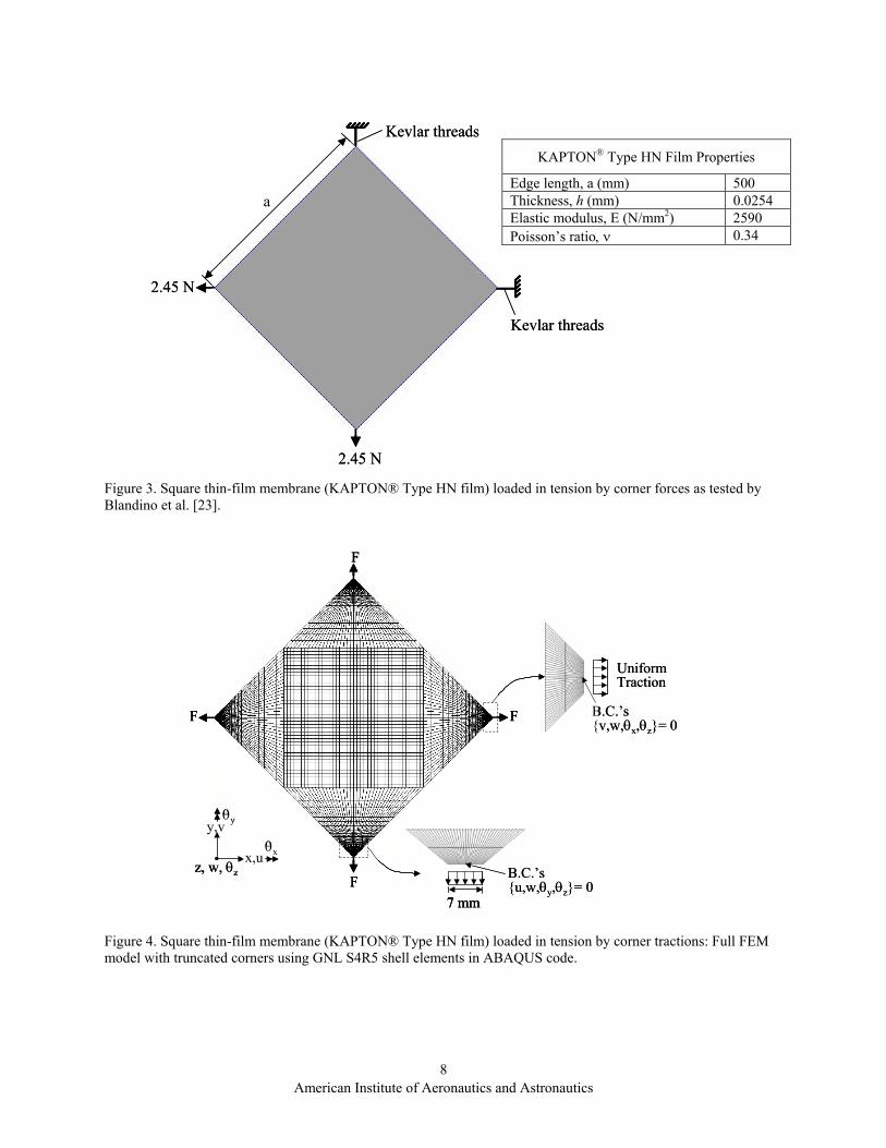
KAPTON® Type HN Film Properties
Edge length, a (mm) 500 Thickness, h (mm) 0.0254 Elastic modulus, E (N/mm2) 2590 Poisson’s ratio, ν 0.34
2.45 N
2.45 N
Kevlar threads
Kevlar threads
a
2.45 N
2.45 N
Kevlar threads
Kevlar threads
a
Figure 3. Square thin-film membrane (KAPTON® Type HN film) loaded in tension by corner forces as tested by Blandino et al. [23].
7 mm
F
F
F
F
B.C.’s{u,w,θy,θz}= 0
B.C.’s{v,w,θx,θz}= 0
UniformTraction
y,v
x,uθx
θy
z, w, θz
7 mm
F
F
F
F
7 mm
F
F
F
F
B.C.’s{u,w,θy,θz}= 0
B.C.’s{v,w,θx,θz}= 0
UniformTraction
y,v
x,uθx
θy
z, w, θz
y,v
x,uθx
θy
z, w, θz
Figure 4. Square thin-film membrane (KAPTON® Type HN film) loaded in tension by corner tractions: Full FEM model with truncated corners using GNL S4R5 shell elements in ABAQUS code.
American Institute of Aeronautics and Astronautics
8
w (mm) w (mm)
(a) Experiment (Capacitance sensor measurement) (b) GNL/FEM Shell Results (ABAQUS)
Figure 5. Wrinkling deformations of square thin-film membrane (KAPTON® Type HN film) loaded in tension by corner tractions (a) Experiment (Capacitance sensor measurement) [23], and (b) GNL/FEM shell analysis (ABAQUS-S4R5).
Symmetry B.C.’s
Sym
met
ry B
.C.’s
F/2
F/2
Wmid
A
B
x
UniformTraction
B.C.’s{v,w,θx,θz}= 0
y,v
x,uθx
θy
z, w, θz
Symmetry B.C.’s
Sym
met
ry B
.C.’s
F/2
F/2
Wmid
A
B
x
UniformTraction
B.C.’s{v,w,θx,θz}= 0
Symmetry B.C.’s
Sym
met
ry B
.C.’s
F/2
F/2
Wmid
A
B
x
UniformTraction
B.C.’s{v,w,θx,θz}= 0
y,v
x,uθx
θy
z, w, θz
y,v
x,uθx
θy
z, w, θz
Figure 6. Square thin-film membrane (KAPTON® Type HN film) loaded in tension by corner tractions: Symmetric-quadrant model with truncated corners used in parametric studies.
American Institute of Aeronautics and Astronautics
9
0.00.001
18.0 16.0
14.0 12.0
Wmid/h 10.0 8.0
6.0
4.0 2.0
0.01 0.1 1.0 10.0
Imperfection amplitude parameter, α Figure 7. Square thin-film membrane (KAPTON® Type HN film) loaded in tension by corner tractions: Effect of imperfection amplitude on the development of wrinkling deformations in GNL/FEM shell models.
Region with imposed imperfections
(a) Imperfection Model 1 (b) Imperfection Model 2 (c) Imperfection Model 3 Figure 8. Square thin-film membrane (KAPTON® Type HN film) loaded in tension by corner tractions: Symmetric-quadrant GNL/FEM shell models showing regions of imposed random imperfections.
American Institute of Aeronautics and Astronautics
10

-0.30
-0.20
-0.10
0.00
0.10
0.20
0.30
0.40
0.50
0.60
Wrin
klin
g D
efle
ctio
n, w
(mm
)
Model 1Model 2Model 3
A B
A
B
Figure 9. Square thin-film membrane (KAPTON® Type HN film) loaded in tension by corner tractions: Wrinkling deflection along section A-B corresponding to three imperfection models for a fixed value of the imperfection amplitude parameter, α=0.10.
American Institute of Aeronautics and Astronautics
11