What is Kinematics. Kinematics studies the motion of bodies.

Abaqus Technology Brief
TB-10-KC-1
Revised: December 2010
Key Abaqus Features and Benefits
Large catalog of connector elements to simplify
the representation of mechanical joints with com-plex kinematic and kinetic behavior
Nonlinear analysis capability to account for both
material and geometric nonlinearities
Nonlinear Kinematics and Compliance Simulation of Automobiles
Using a representative automobile model, a rigid body suspension mechanism analysis is first conducted, and the results are compared to those from the Adams multi-body dynamics package. The model is then re-analyzed, allowing for nonlinear response in the suspension compo-nents and the vehicle body.
Finite Element Model
A publicly available finite element model of a 2001 Ford Taurus is selected for this study. The model‟s geometry, material properties and finite element mesh data are ob-tained from the Public Finite Element Model Archive of the National Crash Analysis Center at George Washing-ton University. The model is then modified for the Abaqus K&C simulation.
The Taurus has a MacPherson strut type of suspension in the front and rear of the car, as shown in Figure 1. The various types of joints in the suspension are modeled with connector elements. These specialized elements provide an easy and versatile way to model physical mechanisms with point-to-point connections that can exhibit complex kinematic and kinetic relationships. A list of model joint types and their corresponding Abaqus connector element is provided in Table 1.
Summary
In the automobile industry, kinematics and compliance (K&C) testing is used to evaluate the ride and handling performance of an automobile. The traditional approach to numerical simulation of K&C testing involves the use of multi-body dynamics software, which simplifies the phys-ics by introducing rigid body assumptions.
In this Technology Brief, a new methodology for K&C simulation is demonstrated using Abaqus/Standard. This approach differentiates itself from that of traditional rigid body simulations by accounting for component flexibility as well as geometric and material nonlinearities. Results from a nonlinear analysis are shown to be considerably different from those of a rigid body analysis, indicating that component flexibility plays an important role in K&C testing.
Introduction and Approach
During a typical K&C test, an automobile is held in a test stand so that the body remains fixed while the wheels are free to move. Controlling forces or displacements are ap-plied to the wheels, and the characteristics of the suspen-sion system are measured.
The test considered in this study is a quasi-static process, with forces or displacements applied gradually. Results of interest are parameters such as toe and camber, which are important in evaluating the ride and handling perform-ance of a vehicle.
When simulating a K&C test with multi-body dynamics software using rigid body assumptions, the results of a kinematics study (i.e., no applied forces) in general corre-late well with the test. This is because the deformation of the vehicle components has little influence on suspension system kinematic behavior.
In a compliance study however, where component flexibil-ity plays a more important role, results are often signifi-cantly different from test data. Flexibility effects can be included with techniques such as Component Mode Syn-thesis, but nonlinearity is still neglected.
With the emergence of more sophisticated suspension system designs, a modeling capability that accounts for component flexibility, as well as geometric and material nonlinearities, allows for more realistic K&C simulation.

2
K&C Test Conditions
The kinematics test is performed by prescribing displace-ments to the plates that contact the bottom of the wheels. An upward (bump) or downward (rebound) displacement of 80 mm is applied in two scenarios. In the Double Bump test the plates below the left and right wheels are moved in the same direction at the same time. In the Roll test the right and left wheels are simultaneously moved in oppo-site directions (i.e., the right wheel goes up while the left wheel goes down and vice versa).
The compliance test is performed by applying forces to the bottom of the wheels. The forces are in the longitudi-nal or lateral direction and have a magnitude of 1000 N. They are applied to the right and left wheels in the same direction.
Joint Connector Type
Spring Axial with linear elastic response
Bushing Bushing
Bump stops Axial with nonlinear elastic behavior
Universal Ujoint
Ball Join and Cardan
Rack & Pinion Flow-convert and Slipring
Revolute Hinge
Figure 1: MacPherson strut front (l) and rear (r)
Table 1: Correspondence of suspension joint and Abaqus connector element type
For both tests, the front and the rear part of the suspen-sion are tested separately. A static analysis step pre-cedes the tests to put the structure into equilibrium. Grav-ity is not considered.
Rigid Body Analysis
To validate the Abaqus model, it is reduced to a rigid rep-resentation and the results are compared to those from an equivalent model built in the multi-body dynamics soft-ware Adams.
The Abaqus and Adams rigid body suspension models are shown in Figure 2. In the Abaqus model, each compo-nent of the suspension system is modeled using a single beam element which is defined as a rigid body. In both models the vehicle body is rigid and fixed to the ground. For convenience the subframe bushings in the front of the vehicle are rigid, and the stabilizer bars are not included. Four rigid plates support the wheels. The Abaqus model uses slide-plane connectors to connect the wheels to the plates while the Adams model uses the equivalent IN-PLANE joints.
Figure 2: Rigid body models, Abaqus (l) and Adams (r) Figure 3: Representative parameters from kinematics
simulation; toe in double bump test (top), camber in roll test (bottom)
3
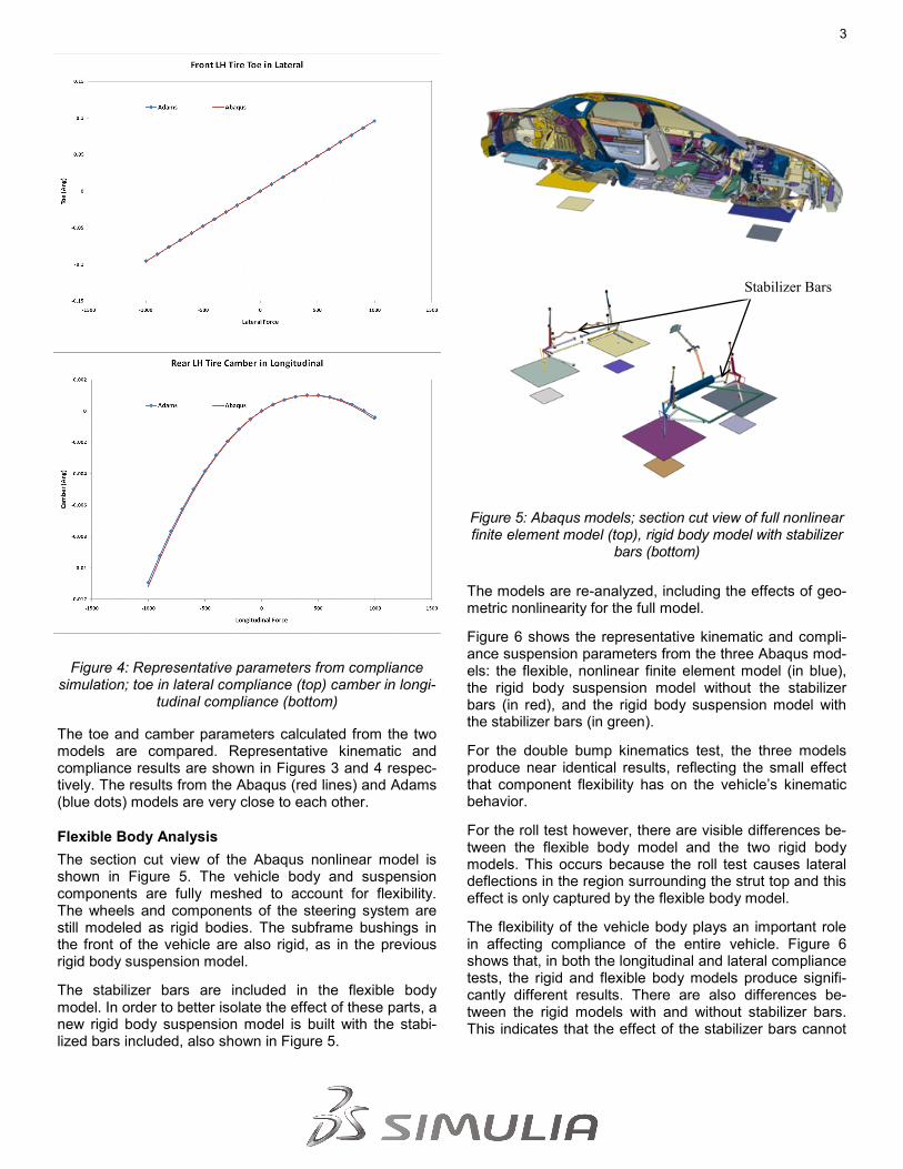
Figure 4: Representative parameters from compliance simulation; toe in lateral compliance (top) camber in longi-
tudinal compliance (bottom)
The toe and camber parameters calculated from the two models are compared. Representative kinematic and compliance results are shown in Figures 3 and 4 respec-tively. The results from the Abaqus (red lines) and Adams (blue dots) models are very close to each other.
Flexible Body Analysis
The section cut view of the Abaqus nonlinear model is shown in Figure 5. The vehicle body and suspension components are fully meshed to account for flexibility. The wheels and components of the steering system are still modeled as rigid bodies. The subframe bushings in the front of the vehicle are also rigid, as in the previous rigid body suspension model.
The stabilizer bars are included in the flexible body model. In order to better isolate the effect of these parts, a new rigid body suspension model is built with the stabi-lized bars included, also shown in Figure 5.
The models are re-analyzed, including the effects of geo-metric nonlinearity for the full model.
Figure 6 shows the representative kinematic and compli-ance suspension parameters from the three Abaqus mod-els: the flexible, nonlinear finite element model (in blue), the rigid body suspension model without the stabilizer bars (in red), and the rigid body suspension model with the stabilizer bars (in green).
For the double bump kinematics test, the three models produce near identical results, reflecting the small effect that component flexibility has on the vehicle‟s kinematic behavior.
For the roll test however, there are visible differences be-tween the flexible body model and the two rigid body models. This occurs because the roll test causes lateral deflections in the region surrounding the strut top and this effect is only captured by the flexible body model.
The flexibility of the vehicle body plays an important role in affecting compliance of the entire vehicle. Figure 6 shows that, in both the longitudinal and lateral compliance tests, the rigid and flexible body models produce signifi-cantly different results. There are also differences be-tween the rigid models with and without stabilizer bars. This indicates that the effect of the stabilizer bars cannot
Stabilizer Bars
Figure 5: Abaqus models; section cut view of full nonlinear finite element model (top), rigid body model with stabilizer
bars (bottom)

4
Figure 6: Flexible and rigid body results; front and rear toe in double bump test (top row), front and rear toe in lateral compliance (middle row), front and rear toe in roll test (bottom row)

5
About SIMULIA SIMULIA is the Dassault Systèmes brand that delivers a scalable portfolio of Realistic Simulation solutions including the Abaqus prod-uct suite for Unified Finite Element Analysis, multiphysics solutions for insight into challenging engineering problems, and lifecycle management solutions for managing simulation data, processes, and intellectual property. By building on established technology, re-spected quality, and superior customer service, SIMULIA makes realistic simulation an integral business practice that improves prod-uct performance, reduces physical prototypes, and drives innovation. Headquartered in Providence, RI, USA, with R&D centers in Providence and in Suresnes, France, SIMULIA provides sales, services, and support through a global network of over 30 regional offices and distributors. For more information, visit www.simulia.com
The 3DS logo, SIMULIA, Abaqus and the Abaqus logo are trademarks or registered trademarks of Dassault Systèmes or its subsidiaries, which include Abaqus, Inc. Other company, product and service
names may be trademarks or service marks of others.
Copyright Dassault Systèmes, 2010
References
1. W.C. Mitchell, R.Simons, T.Sutherland and M.Keena-Levin, “Suspension Geometry: Theory vs. K&C Measure-ment,” SAE 2008-01-2948
Abaqus References
For additional information on the Abaqus capabilities referred to in this brief, please see the following Abaqus 6.11 docu-mentation references:
„Connector Elements,‟ Section 30, Analysis User‟s Manual
be ignored in this case. Figure 7 shows the deformed shape of the front part of the vehicle in the flexible body lateral compliance simulation. It is obvious that local and global deformation due to component flexibility can affect the suspension parameters.
Conclusion
When compared to a more traditional rigid body ap-proach, the nonlinear K&C analysis of a flexible automo-bile model shows that component compliance can have a significant effect on computed suspension parameters. The numerical results are more representative of actual automobile behavior and can facilitate more realistic simulations of modern suspension systems. With its nonlinear analysis capability and versatile modeling func-tionalities, Abaqus is the ideal tool to conduct such simu-lations.
Figure 7: Deformed shape of front part of the vehicle in the flexible body lateral compliance simulation
Figure 6, continued: Flexible and rigid body results; front and rear toe in longitudinal compliance


![05 - kinematics me338 - syllabusbiomechanics.stanford.edu/me338_13/me338_s05.pdf05 - kinematics 1 05 - kinematics holzapfel nonlinear solid mechanics [2000], chapter 2.5-2.8, pages](https://static.fdocuments.in/doc/165x107/604fd0a89fe86818a45365d2/05-kinematics-me338-05-kinematics-1-05-kinematics-holzapfel-nonlinear-solid.jpg)


![KINEMATICS - new.excellencia.co.innew.excellencia.co.in/college/web/pdf/Kinematics-merged.pdf · KINEMATICS KINEMATICS WORKSHEET 1 1) Displacement is a _____ [ ] 1) Vector quantity](https://static.fdocuments.in/doc/165x107/5f356d4687229051801abace/kinematics-new-kinematics-kinematics-worksheet-1-1-displacement-is-a-.jpg)