NONLINEAR FINITE ELEMENT ANALYSIS OF REINFORCED …according to SR EN 1992-1-1:2004 (SR EN...
13
BULETINUL INSTITUTULUI POLITEHNIC DIN IAŞI Publicat de Universitatea Tehnică „Gheorghe Asachi” din Iaşi Tomul LVIII (LXII), Fasc. 1, 2012 Secţia CONSTRUCŢII. ARHITECTURĂ NONLINEAR FINITE ELEMENT ANALYSIS OF REINFORCED CONCRETE SLIT WALLS WITH ANSYS (II) BY SERGIU BĂETU * and IOAN-PETRU CIONGRADI “Gheorghe Asachi” Technical University of Iaşi Faculty of Civil Engineering and Building Services Received: January 5, 2012 Accepted for publication: March 20, 2012 Abstract. An economical design of buildings based on performance takes into account the dissipation of seismic energy accumulated in the structure. In a tall structural wall, plastic hinge formation happens only at the base of the wall and ductility resources of the rest of the wall remains untapped. A solution to increase the performance of a reinforced concrete structural wall is to create a slit zone with shear connections. Yielding of this shear connections may cause increase in energy dissipation. The aim of these solutions is to create an ideal structure for tall multi-storey buildings, that has a rigid behavior at low seismic action (the shear connections behave elastic) and turns into a ductile one in case of a high intensity earthquake action (the shear connections are crushed). In the first part of this study the pushover analyses for slit walls were not very concluding because when the shear connections fail the convergence stops, this being caused by strength degradation and a large displacement of the wall. To capture the strength degradation it was decided to do a cyclic analysis. For the nonlinear analysis it was used a finite element program, ANSYS. Key words: reinforced concrete slit walls; pushover analysis; nonlinear cyclic analysis; energy dissipation. * Corresponding author: e-mail: [email protected]
Transcript of NONLINEAR FINITE ELEMENT ANALYSIS OF REINFORCED …according to SR EN 1992-1-1:2004 (SR EN...
BULETINUL INSTITUTULUI POLITEHNIC DIN IAŞI Publicat de
Universitatea Tehnică „Gheorghe Asachi” din Iaşi Tomul LVIII (LXII), Fasc. 1, 2012
Secţia CONSTRUCŢII. ARHITECTURĂ
NONLINEAR FINITE ELEMENT ANALYSIS OF REINFORCED
CONCRETE SLIT WALLS WITH ANSYS (II)
BY
SERGIU BĂETU * and IOAN-PETRU CIONGRADI
“Gheorghe Asachi” Technical University of Iaşi Faculty of Civil Engineering and Building Services
Received: January 5, 2012 Accepted for publication: March 20, 2012
Abstract. An economical design of buildings based on performance takes
into account the dissipation of seismic energy accumulated in the structure. In a tall structural wall, plastic hinge formation happens only at the base of the wall and ductility resources of the rest of the wall remains untapped. A solution to increase the performance of a reinforced concrete structural wall is to create a slit zone with shear connections. Yielding of this shear connections may cause increase in energy dissipation. The aim of these solutions is to create an ideal structure for tall multi-storey buildings, that has a rigid behavior at low seismic action (the shear connections behave elastic) and turns into a ductile one in case of a high intensity earthquake action (the shear connections are crushed). In the first part of this study the pushover analyses for slit walls were not very concluding because when the shear connections fail the convergence stops, this being caused by strength degradation and a large displacement of the wall. To capture the strength degradation it was decided to do a cyclic analysis. For the nonlinear analysis it was used a finite element program, ANSYS.
Key words: reinforced concrete slit walls; pushover analysis; nonlinear cyclic analysis; energy dissipation.
*Corresponding author: e-mail: [email protected]
100 Sergiu Băetu and Ioan-Petru Ciongradi
1. Introduction
Reinforced concrete walls are important structural elements that are
placed in multistory buildings from seismic zones, because they have a high resistance to lateral earthquake loads. Reinforced concrete structural walls must have sufficient ductility to avoid brittle failure under the action of strong lateral seismic loads. The slit walls with shear connections remove some of the problems encountered with ordinary structural walls. In the first part of this study an important observation was that the applicability of this solution for energy dissipation is more pronounced for tall structural walls from high-rises buildings were the predominant effort is bending. The wall must be sufficiently slender so that the slipping along the connection zone to appear before cracks
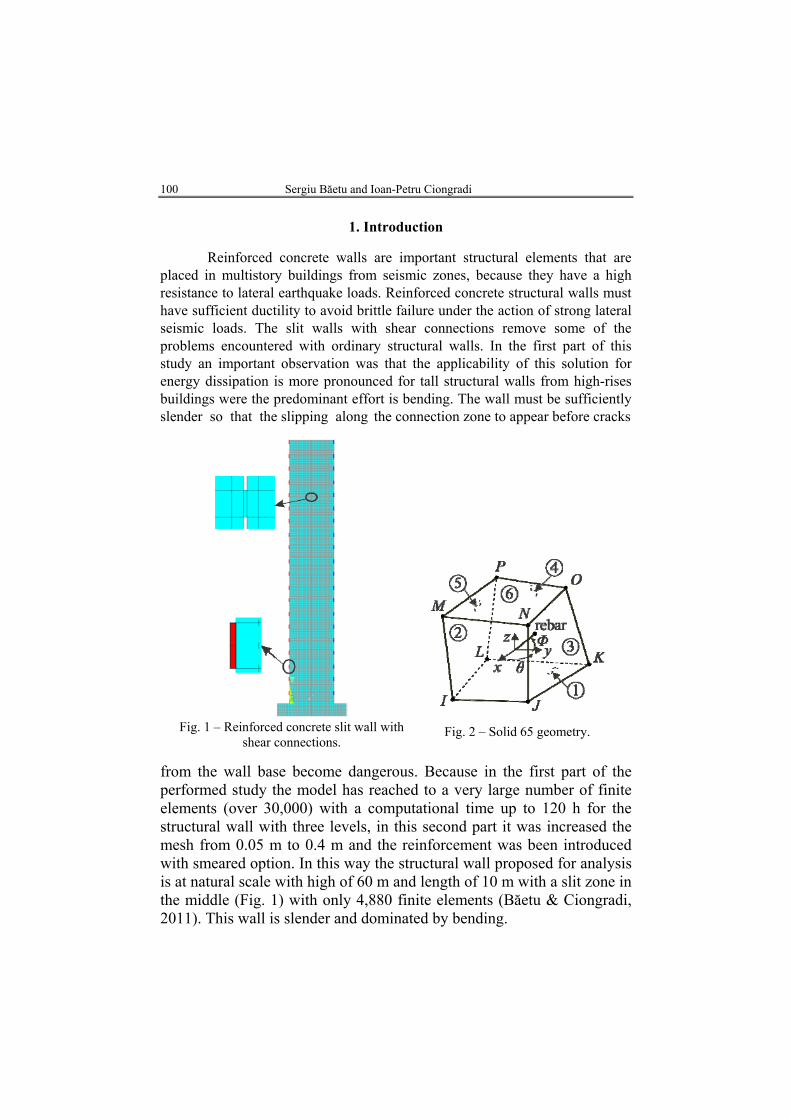
Fig. 1 – Reinforced concrete slit wall with
shear connections.
Fig. 2 – Solid 65 geometry.
from the wall base become dangerous. Because in the first part of the performed study the model has reached to a very large number of finite elements (over 30,000) with a computational time up to 120 h for the structural wall with three levels, in this second part it was increased the mesh from 0.05 m to 0.4 m and the reinforcement was been introduced with smeared option. In this way the structural wall proposed for analysis is at natural scale with high of 60 m and length of 10 m with a slit zone in the middle (Fig. 1) with only 4,880 finite elements (Băetu & Ciongradi, 2011). This wall is slender and dominated by bending.
Bul. Inst. Polit. Iaşi, t. LVIII (LXII), f. 1, 2012 101
2. Finite Element Analysis by ANSYS
2.1. Concrete Modeling
The concrete used in the analysis is C32/40. The Solid 65 element was
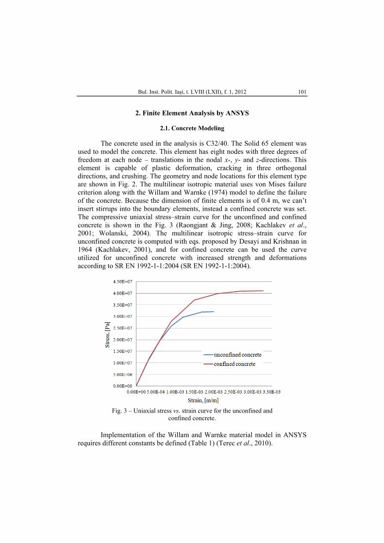
used to model the concrete. This element has eight nodes with three degrees of freedom at each node – translations in the nodal x-, y- and z-directions. This element is capable of plastic deformation, cracking in three orthogonal directions, and crushing. The geometry and node locations for this element type are shown in Fig. 2. The multilinear isotropic material uses von Mises failure criterion along with the Willam and Warnke (1974) model to define the failure of the concrete. Because the dimension of finite elements is of 0.4 m, we can’t insert stirrups into the boundary elements, instead a confined concrete was set. The compressive uniaxial stress–strain curve for the unconfined and confined concrete is shown in the Fig. 3 (Raongjant & Jing, 2008; Kachlakev et al., 2001; Wolanski, 2004). The multilinear isotropic stress–strain curve for unconfined concrete is computed with eqs. proposed by Desayi and Krishnan in 1964 (Kachlakev, 2001), and for confined concrete can be used the curve utilized for unconfined concrete with increased strength and deformations according to SR EN 1992-1-1:2004 (SR EN 1992-1-1:2004).
Fig. 3 – Uniaxial stress vs. strain curve for the unconfined and
confined concrete.
Implementation of the Willam and Warnke material model in ANSYS requires different constants be defined (Table 1) (Terec et al., 2010).
102 Sergiu Băetu and Ioan-Petru Ciongradi
Table 1
Concrete Properties 1 Shear transfer coefficients for an open crack (βt) 0.4 2 Shear transfer coefficients for an closed crack (βc) 0.8 3 Uniaxial tensile cracking stress (fr) 2.2E+006 Pa
unconfined concrete 3.2E+007 Pa
4
Uniaxial crushing stress (fc) confined concrete 4.1E+007 Pa
If the material at an integration point fails in uniaxial, biaxial or triaxial
compression, the material is assumed to crush at that point. In Solid 65, crushing is defined as the complete deterioration of the structural integrity of the material (material spalling). Under conditions were crushing has occurred, material strength is assumed to be degraded and the contribution to the stiffness of an element at the integration point in question can be ignored. Small circles will be shown where the concrete has cracked, and octagons will be shown where the concrete has crushed.
2.2. Reinforcement Modeling
The reinforcement bars may be included in the finite element model in two ways: as a discrete model (individual bars), or through a smeared model (Fig. 2) (Raongjant & Jing, 2008; Kheyroddin & Naderpour, 2008; Kachlakev et al., 2001; Wolanski, 2004). In the first part the reinforcement was modeled using discrete model with Link 8 elements. In this part the analyses will be done with smeared model, because the mesh was done with big finite elements and no individual bars can be inserted. For this model, parameters to be considered are material number, volume ratio and orientation angle (θ and Φ) in X- and Y-directions respectively (Table 2). Volume ratio refers to the ratio of steel to concrete in element.
Table 2
Real Constants for Concrete Constants
Particulars Real constant for rebar 1 (vertical
rebar)
Real constant for rebar 2 (horizontal
rebar)
Real constant for rebar 3 (vertical rebar-
boundary element) Material number 2 2 2
Volume ratio 0.00513 0.00377 0.0308 Orientation angle θ 90 0 90 Orientation angle Φ 0 90 0
Bul. Inst. Polit. Iaşi, t. LVIII (LXII), f. 1, 2012 103
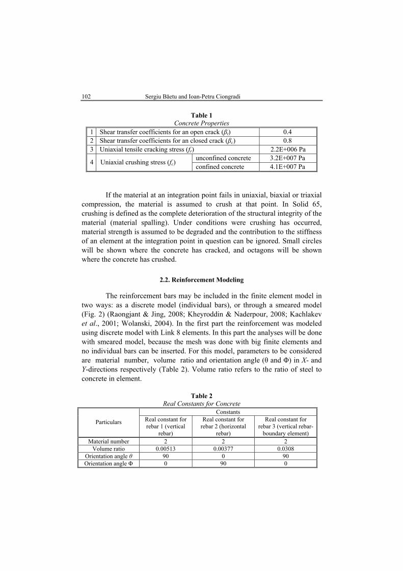
In Fig. 4 is shown the stress–strain curve of reinforcement used in this study. The bilinear kinematic hardening model (BKIN) was used (Kachlakev et al., 2001; Wolanski, 2004). The bilinear model requires the yield stress ( fy = = 3.55E+008 Pa) and the hardening modulus of the steel ( '
sE = 2.1E+009 Pa).
Fig. 4 – Stress vs. strain curve for reinforcement.
2.3. Loading and Boundary Conditions
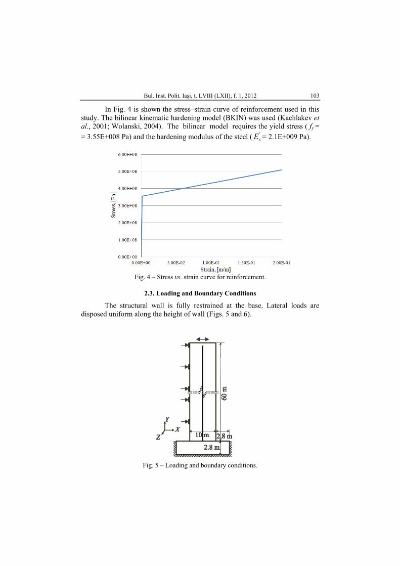
The structural wall is fully restrained at the base. Lateral loads are disposed uniform along the height of wall (Figs. 5 and 6).
Fig. 5 – Loading and boundary conditions.
104 Sergiu Băetu and Ioan-Petru Ciongradi
a
b
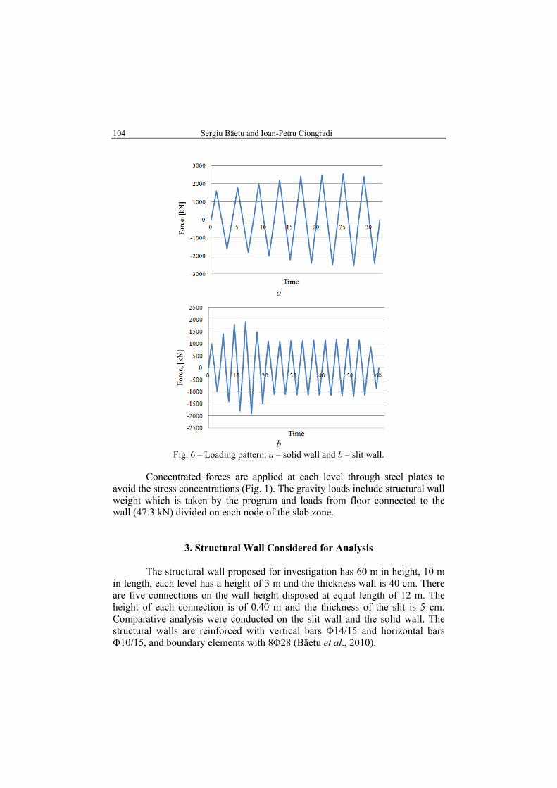
Fig. 6 – Loading pattern: a – solid wall and b – slit wall.
Concentrated forces are applied at each level through steel plates to avoid the stress concentrations (Fig. 1). The gravity loads include structural wall weight which is taken by the program and loads from floor connected to the wall (47.3 kN) divided on each node of the slab zone.
3. Structural Wall Considered for Analysis
The structural wall proposed for investigation has 60 m in height, 10 m in length, each level has a height of 3 m and the thickness wall is 40 cm. There are five connections on the wall height disposed at equal length of 12 m. The height of each connection is of 0.40 m and the thickness of the slit is 5 cm. Comparative analysis were conducted on the slit wall and the solid wall. The structural walls are reinforced with vertical bars Φ14/15 and horizontal bars Φ10/15, and boundary elements with 8Φ28 (Băetu et al., 2010).
Bul. Inst. Polit. Iaşi, t. LVIII (LXII), f. 1, 2012 105
4. Comparison of Analytical Results
4.1. Comparative Pushover Analysis
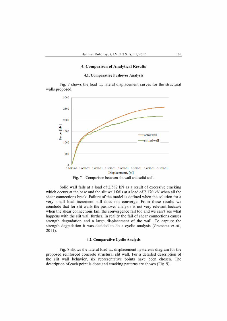
Fig. 7 shows the load vs. lateral displacement curves for the structural
walls proposed.
Fig. 7 – Comparison between slit wall and solid wall.
Solid wall fails at a load of 2,582 kN as a result of excessive cracking
which occurs at the base and the slit wall fails at a load of 2,170 kN when all the shear connections break. Failure of the model is defined when the solution for a very small load increment still does not converge. From these results we conclude that for slit walls the pushover analysis is not very relevant because when the shear connections fail, the convergence fail too and we can’t see what happens with the slit wall further. In reality the fail of shear connections causes strength degradation and a large displacement of the wall. To capture the strength degradation it was decided to do a cyclic analysis (Greeshma et al., 2011).
4.2. Comparative Cyclic Analysis
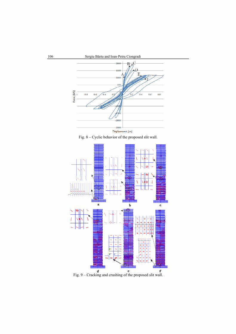
Fig. 8 shows the lateral load vs. displacement hysteresis diagram for the
proposed reinforced concrete structural slit wall. For a detailed description of the slit wall behavior, six representative points have been chosen. The description of each point is done and cracking patterns are shown (Fig. 9).
106 Sergiu Băetu and Ioan-Petru Ciongradi
Fig. 8 – Cyclic behavior of the proposed slit wall.
Fig. 9 – Cracking and crushing of the proposed slit wall.
Bul. Inst. Polit. Iaşi, t. LVIII (LXII), f. 1, 2012 107
A. At this point, the slit wall began to crack. Small cracks were observed in the connections due to shear and at the base of the wall due to bending (Fig. 9 a). Until this point the slit wall behavior is very similar with the behavior of a solid wall with large lateral stiffness.
B. First connection at the bottom of the wall fails (Fig. 9 b). More shear cracks were observed in the other connections. The cracks from the base of the wall extend rapidly on the first five levels. The wall still has a high stiffness.
C. Maximum load was reached at this point. Next two connections have crushed, also the concrete near the connections is crushed too (Fig. 9 c). Almost all of the bottom half of the wall is cracked.
D. The fourth connections fail and almost all the wall is cracked (Fig. 9 d). At this point the stiffness of the wall has decreased.
E. At this point, the fifth (the last) connection failed (Fig. 9 e). The stiffness of the wall is drastically decreased. Slipping along the connections zone has appeared. The cracks from the base of the wall are not still dangerous, because no crushing and spalling of concrete is observed. The fail of shear connections causes strength degradation and a large displacement of the wall. After this point the hysteresis behavior of the slit wall became stable and a lot of hysteretic energy is dissipated.
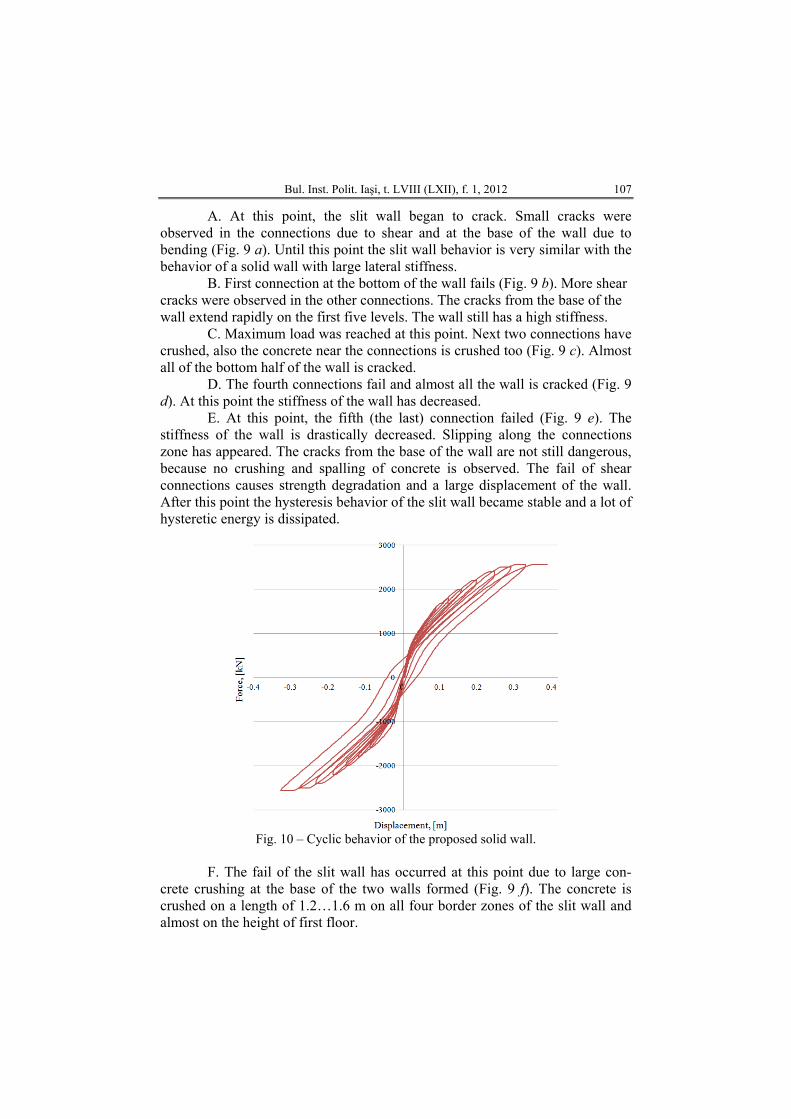
Fig. 10 – Cyclic behavior of the proposed solid wall.
F. The fail of the slit wall has occurred at this point due to large con-
crete crushing at the base of the two walls formed (Fig. 9 f). The concrete is crushed on a length of 1.2…1.6 m on all four border zones of the slit wall and almost on the height of first floor.
108 Sergiu Băetu and Ioan-Petru Ciongradi
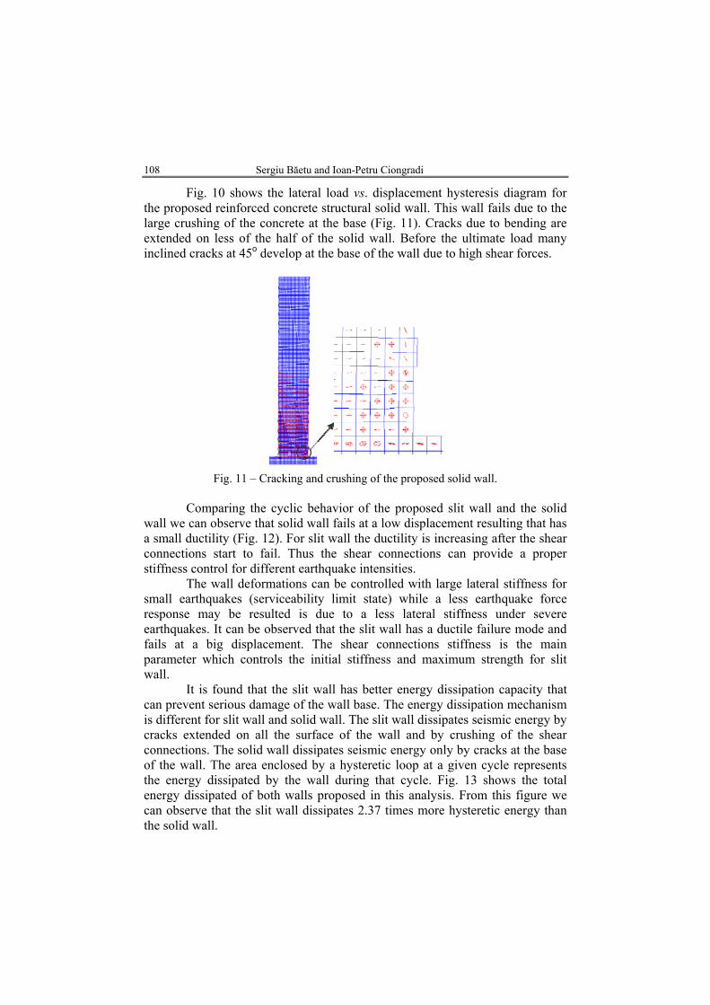
Fig. 10 shows the lateral load vs. displacement hysteresis diagram for the proposed reinforced concrete structural solid wall. This wall fails due to the large crushing of the concrete at the base (Fig. 11). Cracks due to bending are extended on less of the half of the solid wall. Before the ultimate load many inclined cracks at 45o develop at the base of the wall due to high shear forces.
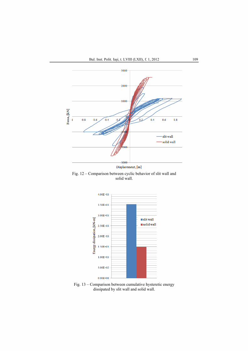
Fig. 11 – Cracking and crushing of the proposed solid wall. Comparing the cyclic behavior of the proposed slit wall and the solid
wall we can observe that solid wall fails at a low displacement resulting that has a small ductility (Fig. 12). For slit wall the ductility is increasing after the shear connections start to fail. Thus the shear connections can provide a proper stiffness control for different earthquake intensities.
The wall deformations can be controlled with large lateral stiffness for small earthquakes (serviceability limit state) while a less earthquake force response may be resulted is due to a less lateral stiffness under severe earthquakes. It can be observed that the slit wall has a ductile failure mode and fails at a big displacement. The shear connections stiffness is the main parameter which controls the initial stiffness and maximum strength for slit wall.
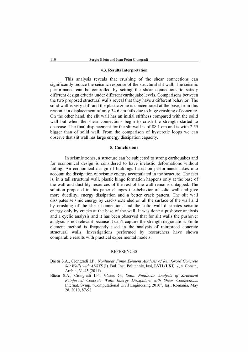
It is found that the slit wall has better energy dissipation capacity that can prevent serious damage of the wall base. The energy dissipation mechanism is different for slit wall and solid wall. The slit wall dissipates seismic energy by cracks extended on all the surface of the wall and by crushing of the shear connections. The solid wall dissipates seismic energy only by cracks at the base of the wall. The area enclosed by a hysteretic loop at a given cycle represents the energy dissipated by the wall during that cycle. Fig. 13 shows the total energy dissipated of both walls proposed in this analysis. From this figure we can observe that the slit wall dissipates 2.37 times more hysteretic energy than the solid wall.
Bul. Inst. Polit. Iaşi, t. LVIII (LXII), f. 1, 2012 109
Fig. 12 – Comparison between cyclic behavior of slit wall and
solid wall.
Fig. 13 – Comparison between cumulative hysteretic energy dissipated by slit wall and solid wall.
110 Sergiu Băetu and Ioan-Petru Ciongradi
4.3. Results Interpretation
This analysis reveals that crushing of the shear connections can significantly reduce the seismic response of the structural slit wall. The seismic performance can be controlled by setting the shear connections to satisfy different design criteria under different earthquake levels. Comparisons between the two proposed structural walls reveal that they have a different behavior. The solid wall is very stiff and the plastic zone is concentrated at the base, from this reason at a displacement of only 34.6 cm fails due to huge crushing of concrete. On the other hand, the slit wall has an initial stiffness compared with the solid wall but when the shear connections begin to crush the strength started to decrease. The final displacement for the slit wall is of 88.1 cm and is with 2.55 bigger than of solid wall. From the comparison of hysteretic loops we can observe that slit wall has large energy dissipation capacity.
5. Conclusions
In seismic zones, a structure can be subjected to strong earthquakes and
for economical design is considered to have inelastic deformations without failing. An economical design of buildings based on performance takes into account the dissipation of seismic energy accumulated in the structure. The fact is, in a tall structural wall, plastic hinge formation happens only at the base of the wall and ductility resources of the rest of the wall remains untapped. The solution proposed in this paper changes the behavior of solid wall and give more ductility, energy dissipation and a better crack pattern. The slit wall dissipates seismic energy by cracks extended on all the surface of the wall and by crushing of the shear connections and the solid wall dissipates seismic energy only by cracks at the base of the wall. It was done a pushover analysis and a cyclic analysis and it has been observed that for slit walls the pushover analysis is not relevant because it can’t capture the strength degradation. Finite element method is frequently used in the analysis of reinforced concrete structural walls. Investigations performed by researchers have shown comparable results with practical experimental models.
REFERENCES Băetu S.A., Ciongradi I.P., Nonlinear Finite Element Analysis of Reinforced Concrete
Slit Walls with ANSYS (I). Bul. Inst. Politehnic, Iaşi, LVII (LXI), 1, s. Constr., Archit., 31-45 (2011).
Băetu S.A., Ciongradi I.P., Văsieş G., Static Nonlinear Analysis of Structural Reinforced Concrete Walls Energy Dissipators with Shear Connections. Internat. Symp. “Computational Civil Engineering 2010”, Iaşi, Romania, May 28, 2010, 87-98.
Bul. Inst. Polit. Iaşi, t. LVIII (LXII), f. 1, 2012 111
Greeshma S., Jaya K.P., Annilet S.L., Analysis of Flanged Shear Wall Using ANSYS Concrete Model. Internat. J. for Civil a. Struct. Engng., 2, 2, 454-465 (2011).
Kachlakev D., Miller T., Yim S., Finite Element Modeling of Reinforced Concrete Structures Strengthened with frp Laminates. Oregon Dept. of Transp., USA, Res. Group, Final Report SPR 316, May 2001.
Kheyroddin A., Naderpour H., Nonlinear Finite Element Analysis of Composite RC Shear Walls. Iran. J. of Sci. & Techn., 32, B2, 79-89 (2008).
Raongjant W., Jing M., Finite Element Analysis on Lightweight Reinforced Concrete Shear Walls with Different Web Reinforcement. The Sixth PSU Engng. Conf., Songkhla, Thailand, May 8-9, 2008, 61-67.
Terec L., Bugnariu T., Păstrav M., Analiza neliniară a cadrelor din beton armat cu pereţi turnaţi in situ. Roman. J. of Mater., 40, 214-221 (2010).
Wolanski J.A., Flexural Behavior of Reinforced and Prestressed Concrete Beams Using Finite Element Analysis. M. Sc. Diss., Marquette Univ., Milwaukee, Wisconsin, USA, 2004.
* * * Proiectarea structurilor din beton. SR EN 1992-1-1:2004.
ANALIZA NELINIARĂ A PEREŢILOR ŞLIŢAŢI DIN BETON ARMAT CU PROGRAMUL DE ELEMENT FINIT ANSYS (II)
(Rezumat)
O proiectare economică a clădirilor, bazată pe performanţă, ia în considerare
disiparea energiei seismice acumulate în clădire. Într-un perete structural înalt, zona plastică este concentrată la bază şi resursele de ductilitate din restul peretelui rămân neatinse. O soluţie pentru a creşte performanţa peretelui structural din beton armat este crearea unei zone şliţate cu conexiuni scurte. Plastifierea acestor conexiuni scurte poate cauza creşterea energiei disipate. Obiectivul acestei soluţii este de a creea o structură ideală pentru clădirile înalte, cu o comportare rigidă la încărcări seismice reduse, care se transformă într-o structură ductilă disipatoare de energie la încărcări seismice ridicate. Analizele pushover efectuate în prima parte a acestui studiu asupra pereţilor şliţaţi nu au oferit rezultate convingătoare deoarece atunci când conexiunile scurte cedau, modelul nu mai era convergent ca urmare a degradării rezistenţei şi deplasărilor mari. Pentru a captura degradarea rezistenţei s-a decis ca peretele sa fie analizat la încărcări ciclice. Analizele ciclice neliniare au fost făcute cu programul cu element finit, ANSYS.