Modelling Damage Evolution in Composite Laminates Subjected to Low Velocity Impact

2013 SIMULIA Regional User Meeting
Nonlinear Analysis of Fiber-Reinforced Composite Laminates
Subjected to Uniaxial Compressive Load
Hsuan-Teh Hu Department of Civil Engineering, National Cheng Kung University, Tainan, Taiwan 701, R.O.C.
Wen-Pin Lin Department of Civil Engineering, Chinese Military Academy, Fengshan, Taiwan 830, R.O.C.
Lung-Shen Ke Department of Civil Engineering, National Cheng Kung University, Tainan, Taiwan 701, R.O.C.
ABSTRACT
A nonlinear constitutive model together with a mixed failure criterion for a single lamina is developed to simulate the behavior of composite laminates under uniaxial compression. In the model, fiber and matrix are assumed to behave elastic-plastic and the in-plane shear to behave nonlinear with a variable shear parameter. The damage onset for individual lamina is detected by a mixed failure criterion, which is composed of the Tsai-Wu criterion and the maximum stress criterion. After damage is taken place within the lamina, fiber and in-plane shear are assumed to exhibit brittle behavior and matrix to exhibit degrading behavior. This material model has been tested against experimental data and good agreement has been obtained. 1. Introduction
Due to lightweight and high strength, the use of fiber-reinforced composite laminate materials (Fig. 1) in aerospace industry, mechanical engineering and applied engineering has increased rapidly in recent years. In numerous cases involving the design of composite structures, there is a need for more refined analysis that takes into account phenomena such as progressive failure and inelastic or nonlinear deformation of the composite materials1,2. Such analysis is required not only to predict the deformational response, but also to provide a method to evaluate the accurate stresses to be used in failure predictions. It is well known that unidirectional fibrous composites exhibit severe nonlinearity in their in-plane shear stress-strain relations3. In addition, deviation from linearity is also observed with in-plane transverse loading but the degree of nonlinearity is not comparable to that observed with the in-plane shear4,5. Therefore, appropriate modeling of the nonlinear behavior of FRP becomes crucial.
A significant number of macro-mechanical models have been proposed to represent the constitutive relation of fiber-reinforced composite materials such as nonlinear elasticity models3,5,6, plasticity models7-11, or damage theory coupled with elasticity12. In addition, various failure criteria have also been proposed to predict the onset of damage in single layer within the fiber-reinforced
composites, i.e. limit theories13, polynomial theories14,15, and direct mode determining theories16-19. As for the post-damage process of individual lamina, two idealized types of failure modes have been defined in the previous study8; namely, brittle and ductile. For the brittle mode, the material is assumed to give up its entire stiffness and strength in the dominant stress direction as the damage is reached, whereas for the ductile mode the material remains its strength but loses its overall stiffness in the damage direction.
Figure 1 Material, element and structure coordinates of fiber reinforced plastics
Obviously, a rationally analysis of individual layer within the laminate under loading must include three parts; namely, pre-damage analysis, damage onset determining, and post-damage
1/14

2013 SIMULIA Regional User Meeting
analysis. In the pre-damage analysis, the proper constitutive model of lamina is a key tool to describe the real behavior of each layer within the laminate under loading. In the previous study, it is assumed that the fiber and matrix perform as elastic-plastic behavior8 and the in-plane shear behaves nonlinear with a constant shear parameter17. In this study, it is proposed that the in-plane shear behaves nonlinearly with a variable shear parameter. The difference between these two distinct types of shear parameter is investigated in this literature. In the past, the Tsai-Wu failure criterion14 is the most common criterion used to determine the damage onset of individual layer. However, Zhu and Sankar20 and Lin and Hu21 suggested that the combination of both the Tsai-Wu criterion and the maximum stress criterion, which is called the mixed criterion, was a much better criterion for damage determining of lamina. Thus, in this paper the mixed criterion is employed to determine the damage onset of individual layer within the laminate under loading. For the post-damage analysis, a degrading mode for matrix and brittle modes for fiber and in-plane shear are proposed to simulate the post damage behaviors of individual lamina.
In this paper, a proposed nonlinear analysis model included various post damage modes is introduced first. Second, a material constitutive model considering the nonlinear in-plane shear behavior with variable shear parameter and the elastic-plastic behavior of fiber and matrix is developed. Third, various failure criteria and post damage modes are reviewed, and a mixed failure criterion and the post-damage modes are proposed. Fourth, the laminate governing equations are built up to describe the incremental force-strain relations of the composite laminates. Then, the ABAQUS finite element program22 is used to carry out numerical analyses for laminates with various configurations and various off-axis loads. Finally, numerical results predicted by the proposed nonlinear analysis model are tested against the experimental data of Petit and Waddoups5 and compared with those predicted by other failure criteria and post damage modes. 2. Nonlinear Analysis Model 2.1 Proposed stress-strain curves and post damage model
For a single lamina subjected to tensile loading, the stress-strain curves of the proposed nonlinear analysis model are shown in Figs. 2a and 2c. It is assumed that the material response can be represented by bilinear stress-strain curves in the principal material directions, i.e. 1 direction (fiber direction) and 2 direction (transverse direction), of the lamina. Let Xyt and Xut be the yield strength and the ultimate strength of the lamina for tension in 1 direction, Yyt and Yut be the yield strength and the ultimate strength of the lamina for tension in 2 direction. For the elastic regions, i.e.
1 Xyt and 2 Yyt , the elastic moduli are denoted by Eiie ( i 1,2 ). For the plastic regions, i.e. 1X Xyt ut and 2Y Yyt ut , the elastic moduli are denoted by Eiip ( i 1,2 ). For a lamina subjected to compressive loading, the stress-strain curves are shown in Fig. 2b and 2d. It is obvious that Xyc and Xuc are the yield strength and the ultimate strength of the lamina for compression in 1 direction and that Yyc and Yuc are the yield strength and the ultimate strength of the lamina for compression in 2 direction. Let S be the ultimate in-plane shear strength. It is assumed that the in-plane shear in 1-2 direction can be modeled by a nonlinear stress-strain curve as shown in Fig. 2e.
Figure 2 Stress-strain curves of the proposed nonlinear failure model
2/14

2013 SIMULIA Regional User Meeting
For the post-damage region, the strengths are dropped to zero (brittle modes) in 1 direction (Figs. 2a and 2b) and 1-2 direction (Fig. 2e). However, the elastic stiffness is assumed to have a negative modulus 22E f (degrading mode) in 2 direction (Figs. 2c and 2d). This means that the damaged lamina unloads in the transverse direction through a negative tangent modulus until no load remains in the lamina. 2.2 Nonlinear constitutive model of the lamina
For fiber-composite laminate materials, each lamina can be considered as an orthotropic layer in a plane stress condition. Taking into account the elastic-plastic behaviors in the 1 direction and 2 direction and the nonlinear behavior on the 1-2 plane within the lamina, the strain-stress relations for an orthotropic lamina in the material coordinates (1,2) can be written as3:
26666 12
12
0S 0 (1)
where 1 , 2 , and 12 represent the strains in 1 direction, 2 direction and 1-2 plane, respectively.
1 , 2 and 12 denote the stresses in 1-direction, 2-direction and 1-2 plane, respectively. The 12 and 21 are Poisson’s ratios and 11E and 22E are the elastic moduli in 1 direction and 2 direction. If the lamina is in the elastic stage in 1 direction or 2 direction, then 11 11E E e or
22 22E E e . If the lamina is in the plastic stage in 1 direction or 2 direction, then 11 11E E p or
22 22E E p . The 12G is the shear modulus and 6666S is a shear parameter to account for the
in-plane shear nonlinearity. The value of 6666S can be determined by a curve fit to pure shear test data.
The incremental stress-strain relations for a nonlinear orthotropic lamina can be given as follows:
1'{ '} [Q ] { '} (2)
2' ' '{ } [Q ] { }t t (3)
where T1 2 12{ '} { , , } ,
T13 23
'{ } { , } ,t T1 2 12{ '} { , , } ,
T13 23
'{ } { , }t and
11 12 22
12 21 12 21
21 11 221
12 21 12 21
212 6666 12
E E 01 1
E E'Q 01 1
10 01/ G 3S
(4)
1 132
2 23
G 0'Q0 G
(5)
The terms 1 and 2 are the shear correction factors and are taken to be 0.83 in this study23. It is assumed that the transverse shear stresses always behave linearly and do not affect the nonlinear in-plane behavior of individual lamina. 3. Failure Criterion and Degradation of Stiffness 3.1 Review of failure criteria
As previously mentioned, failure criteria fall into three basic categories: (1) limit theories13, (2) polynomial theories14,15, and (3) direct mode determining theories16-19. Among them, the maximum stress criterion13, the Tsai-Wu failure criterion14, the Chang failure criterion17, the Rotem failure criterion18 and the Edge failure criterion19 are selected to be reviewed and numerical results based on these failure criteria are compared with each other. 3.1.1 Maximum stress criterion
The maximum stress criterion is the dominant member of the limit failure theory category13. For the plane stress condition, the maximum stress criterion for an orthotropic material can be expressed as follows:
1 1Xut
or 1 1Xuc
(6)
2 1Yut
or 2 1Yuc
(7)
12 1S
(8)
3.1.2 Tsai-Wu failure criterion
The Tsai-Wu failure criterion has a general
21
11 221 1
122 2
11 2212 12
12
1 0E E
1 0E E
10 0G
3/14
2013 SIMULIA Regional User Meeting
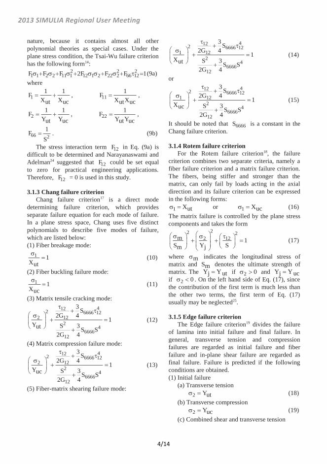
nature, because it contains almost all other polynomial theories as special cases. Under the plane stress condition, the Tsai-Wu failure criterion has the following form14:
2 2 21 1 2 2 11 1 12 1 2 22 2 66 12F F F 2F F F 1(9a)
where
11 1F
X Xut uc, 11
1FX Xut uc
,
21 1F
Y Yut uc, 22
1FY Yut uc
,
66 21F
S. (9b)
The stress interaction term 12F in Eq. (9a) is difficult to be determined and Narayanaswami and Adelman24 suggested that 12F could be set equal to zero for practical engineering applications. Therefore, 12F = 0 is used in this study. 3.1.3 Chang failure criterion
Chang failure criterion17 is a direct mode determining failure criterion, which provides separate failure equation for each mode of failure. In a plane stress space, Chang uses five distinct polynomials to describe five modes of failure, which are listed below: (1) Fiber breakage mode:
1 1Xut
(10)
(2) Fiber buckling failure mode: 1 1
Xuc (11)
(3) Matrix tensile cracking mode: 4122 6666 12
2 122
46666
12
3 S2G 4 1
Y S 3ut S S2G 4
(12)
(4) Matrix compression failure mode: 4122 6666 12
2 122
46666
12
3 S2G 4 1
Y S 3uc S S2G 4
(13)
(5) Fiber-matrix shearing failure mode:
4122 6666 121 12
24
666612
3 S2G 4 1
X S 3ut S S2G 4
(14)
or 4122 6666 12
1 122
46666
12
3 S2G 4 1
X S 3uc S S2G 4
(15)
It should be noted that 6666S is a constant in the Chang failure criterion. 3.1.4 Rotem failure criterion
For the Rotem failure criterion18, the failure criterion combines two separate criteria, namely a fiber failure criterion and a matrix failure criterion. The fibers, being stiffer and stronger than the matrix, can only fail by loads acting in the axial direction and its failure criterion can be expressed in the following forms:
1 Xut or 1 Xuc (16) The matrix failure is controlled by the plane stress components and takes the form
22 22 12m 1
S Y Sm j (17)
where m indicates the longitudinal stress of matrix and Sm denotes the ultimate strength of matrix. The Y Yj ut if 2 0 and Y Yj uc if 2 0 . On the left hand side of Eq. (17), since the contribution of the first term is much less than the other two terms, the first term of Eq. (17) usually may be neglected25. 3.1.5 Edge failure criterion
The Edge failure criterion19 divides the failure of lamina into initial failure and final failure. In general, transverse tension and compression failures are regarded as initial failure and fiber failure and in-plane shear failure are regarded as final failure. Failure is predicted if the following conditions are obtained. (1) Initial failure
(a) Transverse tension 2 Yut (18)
(b) Transverse compression 2 Yuc (19)
(c) Combined shear and transverse tension
4/14

2013 SIMULIA Regional User Meeting
2 22 1 2
ut1
Y S (20)
(d) Combined shear and transverse compression
2 2
2 1 2
uc1
Y S (21)
(2) Final failure (a) Longitudinal tension
1 Xut (22) (b) Longitudinal compression
1 Xuc (23) (c) In-plane shear
12 S (24) (d) Combined longitudinal tension and shear
121 1X Sut
(25)
(e) Combined longitudinal compression and shear
121 1X Suc
(26)
3.2 Proposed mixed failure criterion
Although the Tsai-Wu failure criterion is widely used in determining the damage onset of a lamina, there are some drawbacks with it. Among them is the fact that the failure stress of fiber in a lamina may exceed the strength of material for the case of symmetric angle-ply laminates with small fiber angle (say o o0 20 ) subjected to off-axis tension21. In order to eliminate this unreasonable phenomenon, the limitation of the maximum stress of the lamina in fiber direction is added into the Tsai-Wu failure criterion to obtain a mixed failure criterion, which has the following formulations:
2 2 21 1 2 2 11 1 22 2 66 12F F F F F 1 (27)
and 1 1
Xut or 1 1
Xuc (28)
3.3 Normalized failure stresses and failure contribution
The Tsai-Wu failure criterion and the proposed mixed failure criterion consider the coupling effect of in-plane stresses, 1 , 2 and 12 , in the lamina when the collapse occurs. In order to figure out the individual stress ratio in the lamina,
the normalized failure stresses are defined, which represent the stress ratios (failure stresses/corresponding strengths) in the lamina for various stresses at the onset of collapse. The expressions for the normalized failure stresses are described as follow:
1111
f( )f n Xut or 11
11f( )f n Xuc
(29a)
2222
f( )f n Yut or 22
22f( )f n Yuc
(29b)
1212
f( )f n S (29c)
where 11( )f n , 22( )f n and 12( )f n denote the normalized failure stresses in 1 direction, 2 direction, and 1-2 plane of the lamina, respectively. The 11f , 22f and 12f are the stresses of the lamina in 1 direction, 2 direction and 1-2 plane at the onset of failure. 3.4 Degradation models
Upon damage within the lamina occurring, the material properties begin to degrade. Material degradation within the damaged area is evaluated based on the mode of failure predicted by the failure criterion. Therefore, the residual stiffnesses of composites strongly depend on the mode of failure in each layer. According to the literature, the degradation models for each layer can be separated into three idealized types of failure modes named as brittle, ductile8 and degrading mode21. For the brittle mode, the material is assumed to lose its entire stiffness and strength in the dominant stress direction. For the ductile mode the material retains its strength but loses all of its stiffness in the failure direction. For the degrading mode the material is assumed to lose its stiffness and strength in the failure direction gradually until the stress in that direction is reduced to zero.
For the Tsai-Wu failure criterion, it cannot distinguish the failure modes and cannot consider the post failure condition. Although the maximum stress criterion, the Rotem failure criterion and the Edge failure criterion can distinguish the failure modes of material, their failure modes are all assumed to be brittle types in this investigation. 3.4.1 Chang's degradation model
For the Chang failure theory, it not only can distinguish the failure modes but also can consider
5/14
2013 SIMULIA Regional User Meeting
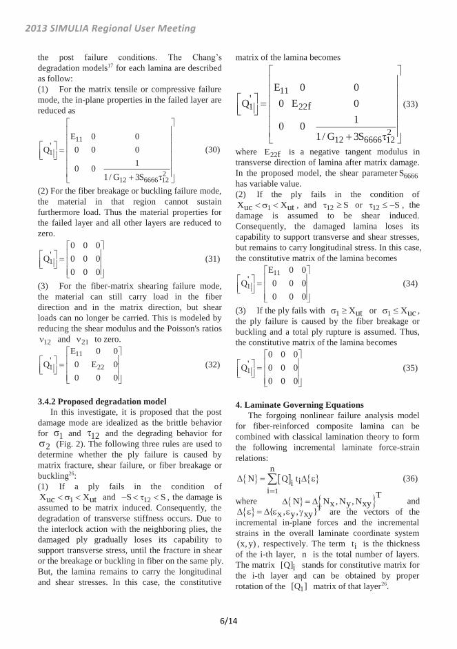
the post failure conditions. The Chang’s degradation models17 for each lamina are described as follow: (1) For the matrix tensile or compressive failure mode, the in-plane properties in the failed layer are reduced as
11
1
212 6666 12
E 0 0'Q 0 0 0
10 01/ G 3S
(30)
(2) For the fiber breakage or buckling failure mode, the material in that region cannot sustain furthermore load. Thus the material properties for the failed layer and all other layers are reduced to zero.
1
0 0 0'Q 0 0 0
0 0 0 (31)
(3) For the fiber-matrix shearing failure mode, the material can still carry load in the fiber direction and in the matrix direction, but shear loads can no longer be carried. This is modeled by reducing the shear modulus and the Poisson's ratios
12 and 21 to zero. 11
1 22
E 0 0'Q 0 E 0
0 0 0 (32)
3.4.2 Proposed degradation model
In this investigate, it is proposed that the post damage mode are idealized as the brittle behavior for 1 and 12 and the degrading behavior for
2 (Fig. 2). The following three rules are used to determine whether the ply failure is caused by matrix fracture, shear failure, or fiber breakage or buckling26: (1) If a ply fails in the condition of
1X Xuc ut and 12S S , the damage is assumed to be matrix induced. Consequently, the degradation of transverse stiffness occurs. Due to the interlock action with the neighboring plies, the damaged ply gradually loses its capability to support transverse stress, until the fracture in shear or the breakage or buckling in fiber on the same ply. But, the lamina remains to carry the longitudinal and shear stresses. In this case, the constitutive
matrix of the lamina becomes
11
1 22
212 6666 12
E 0 0'Q 0 E 0f
10 01/ G 3S
(33)
where 22E f is a negative tangent modulus in transverse direction of lamina after matrix damage. In the proposed model, the shear parameter 6666S has variable value. (2) If the ply fails in the condition of
1X Xuc ut , and 12 S or 12 S , the damage is assumed to be shear induced. Consequently, the damaged lamina loses its capability to support transverse and shear stresses, but remains to carry longitudinal stress. In this case, the constitutive matrix of the lamina becomes
11
1
E 0 0'Q 0 0 0
0 0 0 (34)
(3) If the ply fails with 1 Xut or 1 Xuc , the ply failure is caused by the fiber breakage or buckling and a total ply rupture is assumed. Thus, the constitutive matrix of the lamina becomes
1
0 0 0'Q 0 0 0
0 0 0 (35)
4. Laminate Governing Equations
The forgoing nonlinear failure analysis model for fiber-reinforced composite lamina can be combined with classical lamination theory to form the following incremental laminate force-strain relations:
1
nΔ N Q tii
i (36)
where T
N N , N , Nx y xy and T{ , , }x y xy are the vectors of the
incremental in-plane forces and the incremental strains in the overall laminate coordinate system (x, y) , respectively. The term ti is the thickness of the i-th layer, n is the total number of layers. The matrix [Q]i stands for constitutive matrix for the i-th layer and can be obtained by proper rotation of the 1
'[Q ] matrix of that layer26.
6/14

2013 SIMULIA Regional User Meeting
5. Numerical Analysis 5.1 Numerical simulations and material properties
The aforementioned nonlinear constitutive model combined with various failure criteria and various post damage modes for composite materials are implemented into a FORTRAN subroutine and linked to the Abaqus finite element program22. The analyzed laminate plate is simply supported around all edges and subjected to uniaxial compressive load in longitudinal direction only (Fig. 3). The length of the plate L is equal to 12 cm and the width of the plate W is equal to 2 cm. The laminate plate contains 4 plies with the thickness t of each ply equal to 0.1016 mm. The laminae are assumed to be perfectly bounded and no slipping occurs within the laminate. Since the stress field is uniform throughout the laminate plate, only one eight-node isoparametric shell elements with six degrees of freedom per node (three displacements and three rotations) is used to model the plate. The reduced integration rule together with hourglass stiffness control is employed to formulate the element stiffness matrix22.
Figure 3 Geometry and boundary conditions of composite laminates
In Abaqus program, stresses and strains in material coordinates (1,2,3) are calculated at each incremental step, and evaluated by the failure criteria to determine the occurrence of failure and the mode of failure. Mechanical properties of each lamina in the damaged area are reduced, according to proper degradation models. Stresses and strains are then recalculated to determine any additional damage as a result of stress redistribution at the same load. This procedure continues until no additional damage is found. Then, the next increment of load is pursued. The final collapse load is determined when the composite plates cannot sustain any additional load.
In Abaqus program, stresses and strains in material coordinates (1,2,3) are calculated at each incremental step, and evaluated by the failure criteria to determine the occurrence of failure and the mode of failure. Mechanical properties of each lamina in the damaged area are reduced, according to proper degradation models. Stresses and strains are then recalculated to determine any additional damage as a result of stress redistribution at the same load. This procedure continues until no additional damage is found. Then, the next increment of load is pursued. The final collapse load is determined when the composite plates cannot sustain any additional load.
In order to verify the proposed nonlinear failure analysis model, numerical results generated from the model are compared with the test data of Boron/Epoxy composites5. The material properties of Boron/Epoxy composites used in the analysis are
11E 207 GPa,e 11E 180 GPa,p 22E 21.2 GPa,e 22E 15.9 GPa,p 22E 33.12 GPa,f 12G 7.25 GPa, 12 0.3,
36666S 15.20 GPa (constant) or
-36666 12S 20.61 - 20 exp(- / 0.00337) GPa
(variable), X 828 MPa,yt X 1346 MPa,yc Y 57.9 MPa,yt Y 97.3 MPa,yc X 1370 MPa,ut X 2787 MPa,uc Y 86.3 MPa,ut Y 262 MPa,uc S = 128.6 MPa. It should be noted that the shear parameter
6666S has two types, a constant type and a variable type. The variable shear parameter is obtained by curve fitting from the pure shear test data4,21. 5.2 Verification of the proposed nonlinear constitutive model
It is necessary to assure that the proposed constitutive model can correctly simulate the stress-strain relations in the principal directions and in pure shear of a lamina before predicting the mechanical behavior and failure stresses of composite laminates under various loading. Figure 4 shows the numerical results for a single lamina subjected to pure shear loading against the experimental data5. It is obvious that the shear stress-strain curve simulated by the proposed constitutive model with variable 6666S model agrees with the test data well and is much better than those with linear shear model ( 6666S =0) and nonlinear shear model with 6666S being constant.
7/14

2013 SIMULIA Regional User Meeting
0
20
40
60
80
100
120
140
0 0.01 0.02 0.03 0.04 0.05 0.06
ExperimentLinear shearNonlinear shear, constant S
6666Nonlinear shear, variable S6666
12 (M
Pa)
12 Figure 4 Pure shear stress-strain curve for Boron/Epoxy lamina
0
50
100
150
200
250
300
0 0.005 0.01 0.015 0.02 0.025 0.03 0.035 0.04
ExperimentConstant S
6666Variable S
6666
x (MPa
)
x Figure 5 Uniaxial tensile stress-strain curve for [ 45]s Boron/Epoxy laminate
-3.0
-2.5
-2.0
-1.5
-1.0
-0.5
0.0-0.016-0.012-0.008-0.0040
ExperimentProposed model
1 (GPa
)
1 Figure 6 Longitudinal compressive stress-strain curve for Boron/Epoxy lamina
The results simulated by the variable 6666S model and the constant 6666S model for a
s[ 45 / 45] laminate subjected to uniaxial tension loading against the experimental data5 are shown in Fig. 5. It can be seen that the result simulated by the proposed nonlinear shear model with variable
6666S exhibits better fit with the test data than that
simulated by the nonlinear shear model with constant 6666S .
-0.3
-0.2
-0.1
0.0-0.016-0.012-0.008-0.0040
ExperimentProposed model
2 (GPa
)
2 Figure 7 Transverse compressive stress-strain curve for Boron/Epoxy lamina
Figures 6 and 7 illustrate the numerical results for a single lamina subjected to uniaxial longitudinal compressive loading and uniaxial transverse compressive loading against the experiment data5. It can be seen that the proposed elastic-plastic behavior in the longitudinal direction and transverse direction of the lamina exhibit quite good correlation with the experimental dada. As the result, the proposed material model with variable
6666S is proved to model the nonlinear behavior of composite laminates adequately. 5.3 Comparisons among various post failure modes
The load-deformation behavior of a composite laminate is greatly affected by the stress-strain behavior of individual layer within the laminate and the ultimate strength of a composite laminate is greatly controlled by the post-damage mode of damaged lamina within the laminate. In order to verify the proposed post-damage mode in transverse direction of lamina is a suitable one, three idealized post failure modes, brittle, ductile and degrading modes, are taken into account. Figure 8 shows the uniaxial compressive stress-strain curves predicted by various matrix post failure modes for [ 20]s angle ply laminate against experimental data5. The ultimate loads predicted by the brittle mode and the degrading mode are exactly the same and equal to 0.82 GPa, which is close to the experimental data 0.75 GPa. For the ductile mode, the predicted ultimate load is significantly overestimated and is misleading.
8/14

2013 SIMULIA Regional User Meeting
-1.4
-1.2
-1.0
-0.8
-0.6
-0.4
-0.2
0.0-0.02-0.015-0.01-0.0050
ExperimentBrittleDuctileDegrading
x (GPa
)
x Figure 8 Uniaxial comp. stress-strain curves predicted by various matrix post failure modes for [ 20]s laminate
-0.7
-0.6
-0.5
-0.4
-0.3
-0.2
-0.1
0.0-0.025-0.02-0.015-0.01-0.0050
ExperimentBrittleDuctileDegrading
x (GPa
)
x Figure 9 Uniaxial comp. stress-strain curves predicted by various matrix post failure modes for [ 30]s laminate
-2.0
-1.5
-1.0
-0.5
0.0-0.015-0.01-0.0050
ExperimentBrittleDuctileDegrading
x (GPa
)
x Figure 10 Uniaxial comp. stress-strain curves predicted by various matrix post failure modes for [0 / 90]s laminate
Figure 9 shows the uniaxial compressive stress-strain curves predicted by various matrix post failure modes for [ 30]s angle ply laminate
against experimental data5. The ultimate load predicted by the degrading mode is 0.36 GPa, which is close to the experimental data 0.30 GPa. For brittle mode, instability exists in the fiber direction immediately after the failure of the lamina occurs. As the result, the compressive strain in the laminate is suddenly and significantly increased which is contradicted to the experimental data. When the stress redistribution in the laminate is completed, the stress in the laminate starts to increase again and the predicted ultimate load is 0.44 GPa, which is overestimated. For the ductile mode, the predicted ultimate load is again significantly overestimated. Hence, it is appropriated and justified to use the degrading mode to model the post failure of a lamina.
Figure 10 shows the uniaxial compressive stress-strain curves predicted by various matrix post failure modes for [0 / 90]s cross ply laminate against experimental data5. While the ultimate load predicted by the brittle mode is 1.50 GPa, the ultimate loads predicted by the ductile mode and by the degrading mode are the same and equal to 1.54 GPa. It can be seen that all these predicted ultimate loads are close to the experimental data 1.74 GPa.
-0.5
-0.4
-0.3
-0.2
-0.1
0.0-0.014-0.012-0.01-0.008-0.006-0.004-0.0020
BrittleDuctileDegrading
x (GPa
)
x Figure 11 Uniaxial comp. stress-strain curves predicted by various matrix post failure modes for [15 / 75]s laminate
Figures 11, 12, 13 show the uniaxial compressive stress-strain curves predicted by various matrix post failure modes for [15 / 75] ,s [30 / 60]s and [ 45]s cross ply laminates. Since there are no experimental data to compare, we can only see the trends. It can be observed that the predicted stress-strain curves as well as the ultimate loads with different post failure modes are exactly the same for all these three cross ply laminates. For
9/14

2013 SIMULIA Regional User Meeting
laminates with the [ / ( 90)]s cross ply layup, as the fiber angles are more deviated from 0 and 90 degrees, the stress-strain curves of the laminates exhibit more nonlinear behavior. This is due to the nonlinear in-plane shear effect. In addition, as the fiber angles are more deviated from 0 and 90 degrees, the ultimate loads of the laminates become lower.
-0.3
-0.2
-0.1
0.0-0.025-0.02-0.015-0.01-0.0050
BrittleDuctileDegrading
x (GPa
)
x Figure 12 Uniaxial comp. stress-strain curves predicted by various matrix post failure modes for [30 / 60]s laminate
-0.3
-0.2
-0.1
0.0-0.035-0.03-0.025-0.02-0.015-0.01-0.0050
BrittleDuctileDegrading
x (GPa
)
x Figure 13 Uniaxial comp. stress-strain curves predicted by various matrix post failure modes for [ 45]s laminate 5.4 Comparisons among various failure criteria
The Tsai-Wu failure criterion [14] is the most popular failure criterion for composite laminate and has been extensively used in literature. As mentioned previously, with the Tsai-Wu failure criterion, the failure stress of fiber in a lamina may exceed the strength of material for the case of symmetric angle-ply laminates with small fiber angle subjected to off-axis tension21. Hence, it is replaced by the proposed mixed failure criterion, i.e. the Tsai-Wu failure criterion combined with the
maximum stress criterion. In this section, the proposed mixed failure criterion is compared with other popular criteria such as the Rotem criterion, the Edge criterion and the Chang criterion against experimental data5.
-1.0
-0.8
-0.6
-0.4
-0.2
0.0-0.006-0.005-0.004-0.003-0.002-0.0010
ExperimentRotem criterionEdge criterionChang cruterionMixed criterion
x (GPa
)x
Figure 14 Uniaxial compressive stress-strain curves predicted by various failure criteria for [ 20]s laminate
-0.5
-0.4
-0.3
-0.2
-0.1
0.0-0.006-0.005-0.004-0.003-0.002-0.0010
ExperimentRotem criterionEdge criterionChang criterionMixed criterion
x (GPa
)
x Figure 15 Uniaxial compressive stress-strain curves predicted by various failure criteria for [ 30]s laminate
Figure 14 shows the uniaxial compressive stress-strain curves predicted by various failure criteria for [ 20]s angle ply laminate against experimental data5. The predicted failure loads are -0.82 GPa for the Rotem criterion, -0.78 GPa for the Edge criterion, -0.81 GPa for the Chang criterion and -0.82 GPa for the proposed mixed criterion and the experimental failure load is
0.75 GPa. All the failure loads and the stiffnesses of the laminate predicted by the four criteria are reasonably close to the experimental data.
Figure 15 shows the uniaxial compressive stress-strain curves predicted by various failure
10/14

2013 SIMULIA Regional User Meeting
criteria for [ 30]s angle ply laminate against experimental data5. The predicted failure loads are -0.41 GPa for the Rotem criterion, -0.36 GPa for the Edge criterion, -0.37 GPa for the Chang criterion and -0.36 GPa for the mixed criterion and the experimental failure load is -0.30 GPa. It can be seen that the Rotem criterion overestimates the stiffness and the failure load of the laminate than the other three criteria. Although, the failure loads of the laminate predicted by the other three criteria are also higher than the experimental data, the stiffnesses of the laminate predicted by the other three criteria are pretty well.
-0.4
-0.3
-0.2
-0.1
0.0-0.035-0.03-0.025-0.02-0.015-0.01-0.0050
ExperimentRotem criterionEdge criterionChang criterionMixed criterion
x (GPa
)
x Figure 16 Uniaxial compressive stress-strain curves predicted by various failure criteria for [ 60]s laminate
-2.0
-1.5
-1.0
-0.5
0.0-0.015-0.01-0.0050
ExperimentRotem criterionEdge criterionChang criterionMixed criterion
x (GPa
)
x Figure 17 Uniaxial compressive stress-strain curves predicted by various failure criteria for [0 / 90]s laminate
Figure 16 shows the uniaxial compressive stress-strain curves predicted by various failure criteria for [ 60]s angle ply laminate against experimental data5. The predicted failure loads are -0.23 GPa for the Rotem criterion, -0.23 GPa for the Edge criterion, -0.25 GPa for the Chang
criterion and -0.25 GPa for the mixed criterion and the experimental failure load is -0.39 GPa. Although, the failure loads of the laminate predicted by all criteria are significantly underestimated than the experimental data, the stress-strain curve predicted by the Rotem criterion still deviates from those predicted by the other three criteria.
Figure 17 shows the uniaxial compressive stress-strain curves predicted by various failure criteria for [0 / 90]s cross ply laminate against experimental data5. The predicted failure loads are -1.50 GPa for the Rotem criterion, -1.50 GPa for the Edge criterion, -1.54 GPa for the Chang criterion and -1.54 GPa for the mixed criterion and the experimental failure load is -1.74 GPa. Again all the failure loads and the stiffnesses of the laminate predicted by the four criteria are reasonably close to the experimental data.
-3.0
-2.5
-2.0
-1.5
-1.0
-0.5
0.00 10 20 30 40 50 60 70 80 90
ExperimentChang criterionEdge criterionRotem criterionTsai-Wu criterionMixed criterion
Failu
re st
ress
xf
(MPa
)
(degrees) Figure 18 Uniaxial compressive failure stresses predicted by various failure criteria for [ ]s angle ply laminates
Figure 18 shows the uniaxial compressive failure stresses xf predicted by various failure criteria for [ ]s angle ply laminates against experimental data5. Figure 19 shows the normalized material failure stresses predicted by the various failure criteria for [ ]s angle ply laminates subjected to uniaxial compressive loading. It can be observed that the failure stress xf and the normalized failure stresses predicted by the Tsai-Wu failure criterion and the proposed mixed failure criterion are almost the same only with a little discrepancy in the neighborhood of the angle
o45 . It should be noted that around the region o45 , the predicted normalized failure stress
12( )f of the Tsai-Wu failure criterion exceeds the
11/14

2013 SIMULIA Regional User Meeting
value 1 (Fig. 19a), which is unreasonable and unlike to occur. That is the reason why the authors propose the mixed failure criterion, as the cases of laminates subjected to uniaxial tensile loads21.
-1.5
-1.0
-0.5
0.0
0.5
1.0
1.5
0 10 20 30 40 50 60 70 80 90
Mixed criterionTsai-Wu criterionChang criterion
Nor
mal
ized
failu
re st
ress
es
(degrees)
(11f
)n
(22f
)n
( 12f)n
(a)
-1.5
-1.0
-0.5
0.0
0.5
1.0
1.5
0 10 20 30 40 50 60 70 80 90
Mixed criterionEdge criterionRotem criterion
Nor
mal
ized
failu
re st
ress
es
(degrees)
(11f
)n
( 12f)n
(22f
)n
(b)
Figure 19 Normalized material failure stresses predicted by various failure criteria for [ ]s angle ply laminates subjected to uniaxial compressive loading
Comparing the Chang failure criterion with the proposed mixed criterion, we can find that the failure stress xf and the normalized failure stresses predicted with these two criteria are about the same except the region o o0 15 . This is because the Chang failure criterion does not consider the joint effect due to axial stress, transverse stress and in-plane shear stress acting simultaneously. When o o0 10 , we can see that the failure of the angle ply laminate is due to axial failure stress 11( )f n for the Chang Criterion (Fig. 19a). If the joint effect of axial stress, transverse stress and in-plane shear stress is considered, such as the Tsai-Wu failure criterion, the predicted failure stress xf and the normalized failure stresses (in absolute values) will not be so high within o o0 15 region.
For the Edge criterion, it can be seen that its
predicted failure stress xf is usually lower than those predicted by other criteria (Fig. 18). The reason caused that is its predicted stresses 1, 2 and 12 are smaller (in absolute value) than those predicted by other criteria, which can be clear seen in Fig. 19b.
For the Rotem criterion, the predicted failure stress xf is usually higher than those predicted by other failure criteria when o45 and lower than those predicted by other failure criteria when
o45 (Fig. 18). When o o0 15 , the Rotem criterion, same as the Chang criterion, does not consider the joint effect due to axial stress, transverse stress and in-plane shear stress acting simultaneously. Hence, it has the similar trend as the Chang criterion. When o o15 80 , the predicted transverse stress 2 by the Rotem criterion is lower than that by mixed criterion and the predicted in-plane shear stress 12 by the Rotem criterion is higher than that by mixed criterion (Fig. 19b). This is due to the Rotem model treating the in-plane shear having a linear behavior. Therefore, it overestimates the in-plane shear stress. After the failure criterion is employed, the transverse stress is then underestimated. 6. Conclusions
This paper presents a material constitutive model for simulating the mechanical response and predicting the ultimate strength of various symmetrical composite laminates subjected to uniaxial compressive load. The model is composed of three parts: (1) nonlinear constitutive model, (2) mixed failure criterion, and (3) post-damage mode. In the nonlinear constitutive model, the fiber and matrix are simulated by elastic-plastic behavior and the in-plane shear is simulated by nonlinear behavior with variable shear parameter, which is a function of in-plane shear strain. The mixed failure criterion is composed of the Tsai-Wu failure criterion and the maximum stress criterion to determine the damage onset of a lamina. The mixed failure criterion can avoided the overestimation of stresses predicted by the Tsai-Wu failure criterion in a lamina. In the post-damage regions, the fiber and the in-plane shear are simulated by a brittle mode and the matrix by a degrading mode. The validity of the constitutive model has been verified against experimental data5 and reasonable accuracy has been achieved.
It has been shown that for laminates with the
12/14

2013 SIMULIA Regional User Meeting
[ / ( 90)]s cross ply layup and subjected to uniaxial compressive load, as the fiber angles are more deviated from 0 and 90 degrees, the stress-strain curves of the laminates exhibit more nonlinear behavior and the ultimate loads of the laminates become lower.
The proposed constitutive model has been compared with other popular failure criteria for [ ]s angle ply laminate subjected to uniaxial compressive load. For the Chang criterion, the predicted failure stress xf is usually higher than the mixed criterion and the Tsai-Wu criterion when
o o0 15 . For the Edge criterion, the predicted failure stress xf is usually lower than the mixed criterion and the Tsai-Wu criterion. For the Rotem criterion, the predicted failure stress xf is usually higher than those predicted by the mixed criterion and the Tsai-Wu criterion when o45 and lower than those predicted by the mixed criterion and the Tsai-Wu criterion when o45 . 7. References
1Hinton M. J., and Soden, P. D., “Predicting Failure in Composite Laminates: Background to the Exercise,” Composite Science and Technology, Vol. 58, No. 7, 1998, pp. 1001-1010.
2Anyfantis, K. N., and Tsouvalis, N. G., “Post Buckling Progressive Failure Analysis of Composite Laminated Stiffened Panels,” Applied Composite Materials, Vol. 19, No. 3-4, 2012, pp. 219-236.
3Hahn, H. T., and Tsai, S. W., “Nonlinear Elastic Behavior of Unidirectional Composite Laminae,” Journal of Composite Materials, Vol. 7, No. 1, 1973, pp. 102-118.
4Jones, R. M., and Morgan, H. S., “Analysis of Nonlinear Stress-Strain Behavior of Fiber-Reinforced Composite Materials,” AIAA Journal, Vol. 15, No., 12, 1977, pp. 1669-1676.
5Petit, P. H., and Waddoups, M. E., “A Method of Predicting the Nonlinear Behavior of Laminated Composites,” Journal of Composite Materials, Vol. 3, No. 1, 1969, pp. 2-19.
6Bogetti, T. A., Hoppel, C. P. R., Harik, V. M., Newill, J. F., and Burns, B. P., Predicting the Nonlinear Response and Progressive Failure of Composite Laminates,” Composites Science and Technology, Vol. 64, No. 3-4, 2004, pp. 329-342.
7Sun, C. T., and Chen J. L., “A Simple Flow Rule for Characterizing Nonlinear Behavior of Fiber Composite,” Journal of Composite Materials, Vol. 23, No. 10, 1989, pp. 1009-1020.
8Vaziri, R., Olson, M. D., and Anderson, D. L., “A Plasticity-Based Constitutive Model for Fibre-Reinforced Composite Laminates,” Journal of Composite Materials, Vol. 25, No. 5, 1991, pp. 512-535.
9Nanda, A., and Kuppusamy, T., “Three-Dimensional Elastic-Plastic Analysis of Laminated Composite Plates,” Composite Structures, Vol. 17, No. 3, 1991, pp. 213-225.
10Griffin, O. H., Kamat, M. P., and Herakovich, C. T., “Three-Dimensional Inelastic Finite Element Analysis of Laminated Composites,” Journal of Composite Materials, Vol. 15, No. 6, 1981, pp. 543-560.
11Kenaga, D., Doyle, J. F., and Sun, C. T., “The Characterization of Boron/Aluminum Composite in the Nonlinear Range as an Orthotropic Elastic-Plastic Material,” Journal of Composite Materials, Vol. 21, No. 6, 1987, pp. 516-531.
12Allen, H., Harris, C. E., and Groves, S. E., “A Thermomechanical Constitutive Theory for Elastic Composites with Distributed Damage-I, Theoretical Development,” International Journal of Solids Structures, Vol. 23, No. 9, 1987, pp. 1301-1318.
13Rowlands, R. E., “Strength (Failure) Theories and Their Experimental Correlation,” Failure Mechanics of Composites, Edited by Sih, G. C., and Skudra, A. M., Elsevier, Amsterdam, 1985, pp.71-125.
14Tsai, S. W., and Wu, E. M., “A General Theory of Strength for Anisotropic Materials,” Journal of Composite Materials, Vol. 5, No. 1, 1971, pp. 58-80.
15Hoffman, O., “The Brittle Strength of Orthotropic Materials,” Journal of Composite Materials, Vol. 1, No. 2, 1967, pp. 200-206.
16Lee, J. D., “Three Dimensional Finite Element Analysis of Damage Accumulation in Composite Laminate,” Computers & Structures, Vol. 15, No. 3, 1982, pp. 335-350.
17Chang, F. K, and Lessard, L. B., “Damage Tolerance of Laminated Composite Containing an Open Hole and Subjected to Compressive Loadings: Part I-Analysis,” Journal of Composite Materials, Vol. 25, No. 1, 1991, pp. 2-43.
18Rotem, A., “Prediction of Laminate Failure with the Rotem Failure Criterion,” Composites Science and Technology, Vol. 58, No. 7, 1998, pp. 1083-1094.
19Edge, E. C., “Stress Based Grant-Sanders Method for Predicting Failure of Composite Laminates,” Composites Science and Technology, Vol. 58, No. 7, 1998, pp. 1033-1041.
20Zhu, H., and Sankar, B. V., “Evaluation of Failure Criteria for Fiber Composites Using Finite Element Micromechanics,” Journal of Composite Materials, Vol. 32, No. 8, 1998, pp. 766-782.
21Lin, W.-P., and Hu, H.-T., “Nonlinear Analysis of Fiber-Reinforced Composite Laminates Subjected to Uniaxial Tensile Load,” Journal of Composite Materials, Vol. 36, No. 12, 2002, pp. 1429-1450.
22Abaqus, Inc., Abaqus Analysis User's Manuals and Example Problems Manuals, Version 6.11, Providence, Rhode Island, 2011.
23Mindlin, R. D., “Influence of Rotatory Inertia and Shear on Flexural Motions of Isotropic Elastic Plate,” Journal of Applied Mechanics, Vol. 18, 1951, pp. 31-38.
13/14

2013 SIMULIA Regional User Meeting
24Narayanaswami, R., Adelman, H. M., “Evaluation of the Tensor Polynomial and Hoffman Strength Theories for Composite Materials,” Journal of Composite Materials, Vol. 11, No. 4, 1977, pp. 366-377.
25Lin, W.-P., “Nonlinear Failure Analysis Model for Fiber-Reinforced Composite Laminate under Uniaxial and Biaxial Tensile Loads,” Ph.D. Thesis, Department of Civil Engineering, National Cheng Kung University, Tainan, Taiwan, R.O.C., 2001.
26Hu, H.-T., “Influence of In-plane Shear Nonlinearity on Buckling and Postbuckling Responses of Composite Laminate Plates and Shells,” Journal of Composite Materials, Vol. 27, No. 2, 1993, pp. 138-151.
14/14