Nondestructive Testing (CALIBRATION) - Hybrid …hybridpetroleum.com/pdfs/Brochure PND, para website...
7
NONDESTRUCTIVE TESTING (CALIBRATION) HPI Nondestructive Testing (CALIBRATION) Hybrid Petroleum institute “His allies at all times” INTRODUCTION Nondestructive test is called to any test carried a material that does not permanently alter the physical, chemical, mechanical or dimensional properties. Nondestructive testing involving negligible or no damage. Different methods of nondestructive testing are based on the application of physical phenomena such as electromagnetic waves, acoustic, elastic, emission of subatomic particles, capillary absorption and any evidence that does not involve considerable damage to the sample examined. The non-destructive testing or NDT are today a large area of research and likewise are a great tool for the industry. This area is intended to support the industry by performing conventional tests (visual inspection, liquid penetrant, ultrasonic, magnetic particles) and unconventional (digital radiography, guided waves, acoustic emission, thermography, etc.) in materials of all kinds. Among the objectives of these tests is to determine the properties and health of a component or equipment, perform materials characterization, support studies of Failure Analysis and Mechanical Integrity. One of the fundamental requirements to perform all the PND's is having calibrated the instruments and devices that are required so that they can make, so in this paper is carried out a review of the requirements for calibration standards grounded in ASME Sec V. The review was conducted to test: • Penetrant Test • Magnetic Test • Ultrasound Test • Acoustic Emission Test • Radiography Test PENETRANT TEST Aluminum block to sensibility A liquid penetrant comparator block shall be made as follows. The liquid penetrant comparator blocks shall be made of aluminum, ASTM B 209, Type 2024, 3⁄8 in. (9.5 mm) thick, and should have approximate face dimensions of 2 in. x 3 in. (50 mm x 75 mm). At the center of each face, an area approximately 1 in. (25 mm) in diameter shall be marked with a 950°F (510°C) temperature-indicating crayon or paint. The marked area shall be heated with a blowtorch, a Bunsen burner, or similar device to a temperature between 950°F (510°C) and 975°F (524°C). Industrial ultrasound angle beam test. Calibration of Nondestructive Testing Devices (PND's)
Transcript of Nondestructive Testing (CALIBRATION) - Hybrid …hybridpetroleum.com/pdfs/Brochure PND, para website...

NONDESTRUCTIVE TESTING (CALIBRATION) HPI
Nondestructive Testing (CALIBRATION)
Hybrid Petroleum institute “His allies at all times”
INTRODUCTION Nondestructive test is called to any test carried a material that does not permanently alter the physical, chemical, mechanical or dimensional properties. Nondestructive testing involving negligible or no damage. Different methods of nondestructive testing are based on the application of physical phenomena such as electromagnetic waves, acoustic, elastic, emission of subatomic particles, capillary absorption and any evidence that does not involve considerable damage to the sample examined. The non-destructive testing or NDT are today a large area of research and likewise are a great tool for the industry. This area is intended to support the industry by performing conventional tests (visual inspection, liquid penetrant, ultrasonic, magnetic particles) and unconventional (digital radiography, guided waves, acoustic emission, thermography, etc.) in materials of all kinds. Among the objectives of these tests is to determine the properties and health of a component or equipment, perform materials characterization, support studies of Failure Analysis and Mechanical Integrity. One of the fundamental requirements to perform all the PND's is having calibrated the instruments and devices that are required so that they can make, so in this paper is carried out a
review of the requirements for calibration standards grounded in ASME Sec V. The review was conducted to test:
• Penetrant Test • Magnetic Test • Ultrasound Test • Acoustic Emission Test • Radiography Test
PENETRANT TEST
Aluminum block to sensibility A liquid penetrant comparator block shall be made as follows. The liquid penetrant comparator blocks shall be made of aluminum, ASTM B 209, Type 2024, 3⁄8 in. (9.5 mm) thick, and should have approximate face dimensions of 2 in. x 3 in. (50 mm x 75 mm). At the center of each face, an area approximately 1 in. (25 mm) in diameter shall be marked with a 950°F (510°C) temperature-indicating crayon or paint. The marked area shall be heated with a blowtorch, a Bunsen burner, or similar device to a temperature between 950°F (510°C) and 975°F (524°C).
Industrial ultrasound angle beam test.
Calibration of Nondestructive Testing Devices (PND's)

NONDESTRUCTIVE TESTING (CALIBRATION) | 2
Penetrant test The specimen shall then be immediately quenched in cold water, which produces a network of fine cracks on each face. The block shall then be dried by heating to approximately 300°F (149°C). After cooling, the block shall be cut in half. One-half of the specimen shall be designated block “A” and the other block “B” for identification in subsequent processing. Figure III-630 illustrates the comparator blocks “A” and “B.” As an alternate to cutting the block in half to make blocks “A” and “B,” separate blocks 2 in. x 3 in. (50 mm x 75 mm) can be made using the heating and quenching technique as described above. Two comparator blocks with closely matched crack patterns may be used. The blocks shall be marked “A” and “B.” TEMPERATURE LESS THAN 40°F (5°C). If it is desired to qualify a liquid penetrant examination procedure at a temperature of less than 40°F (5°C), the proposed procedure shall be applied to block “B” after the block and all materials have been cooled and held at the proposed examination temperature until the comparison is completed. A standard procedure which has previously been demonstrated as suitable for use shall be
applied to block “A” in the 40°F to 125°F (5°C to 52°C) temperature range. The indications of cracks shall be compared between blocks “A” and “B”. If the indications obtained under the proposed conditions on block “B” are essentially the same as obtained on block “A”
during examination at40°Fto 125°F (5°C to 52°C), the proposed procedure shall be considered qualified for use. A procedure qualified at a temperature lower than 40°F (5°C) shall be qualified from that temperature to 40°F (5°C).
MAGNETIC TEST
MAGNETIZING EQUIPMENT Frequency: Magnetizing equipment with an ammeter shall be calibrated at least once a year, or whenever the equipment has been subjected to major electric repair, periodic overhaul, or damage. If equipment has not been in use for a year or more, calibration shall be done prior to first use. LIFTING POWER OF YOKES Prior to use, the magnetizing power of electromagnetic yokes shall have been checked within the past year. The magnetizing power of permanent magnetic yokes shall be checked daily prior to use. The magnetizing power of all yokes shall be checked whenever the yoke has
Figure 1

NONDESTRUCTIVE TESTING (CALIBRATION) | 3
been damaged or repaired. Each alternating current electromagnetic yoke shall have a lifting power of at least 10 lb (4.5 kg) at the maximum pole spacing that will be used. Each direct current or permanent magnetic yoke shall have a lifting power of at least 40 lb (18 kg) at the maximum pole spacing that will be used. Each weight shall be weighed with a scale from a reputable manufacturer and stenciled with the applicable nominal weight prior to first use. A weight need only be verified again if damaged in a manner that could have caused potential loss of material. GAUSSMETERS Hall-Effect probe gaussmeters used to verify magnetizing field strength in accordance with T-754 shall be calibrated at least once a year or whenever the equipment has been subjected to a major repair, periodic overhaul, or damage. If equipment has not been in use for a year or more, calibration shall be done prior to first use. PIE-SHAPED MAGNETIC PARTICLE FIELD INDICATOR The indicator shall be positioned on the surface to be examined, such that the copper-plated side is away from the inspected surface. A suitable field strength is indicated when a clearly defined line (or lines) of magnetic particles form(s) across the copper face of the indicator when the magnetic particles are applied simultaneously with the magnetizing force. When a clearly defined line of particles is not formed, the magnetizing technique shall be changed as needed. Pie- type indicators are best used with dry particle procedures. THE KETOS RING (T-766) The Ketos (Betz) ring specimen (see Figure. 3) shall be used in evaluating and comparing the overall performance and sensitivity of both dry and wet, fluorescent and no fluorescent magnetic particle techniques using a central conductor magnetization technique. (a) Ketos (Betz) Test Ring Material. The tool steel (Ketos) ring should be machined from AISI 01 material in accordance with Figure. 3 Either the machined ring or the steel blank should be annealed at 1650°F (900°C), cooled 50°F (28°C) per hour to 1000°F (540°C) and then air cooled to ambient temperature to give comparable results using similar rings that have had the same treatment. Material and heat treatment are important variables. Experience indicates controlling the softness of the ring by hardness (90 to 95 HRB) alone is insufficient. (b) Using the Test Ring. The test ring (see Figure. 3), is circularly magnetized with full-wave rectified AC passing through a central conductor with a 1 in. to 11 ⁄ 4 in. (25 mm to 32 mm) diameter hole located in the ring center.
The conductor should have a length greater than 16 in. (400 mm). NOTE: The circular shims shown in Figure. 2 illustration (b) also have flaw depths less and greater than 30%.
Figure 2

NONDESTRUCTIVE TESTING (CALIBRATION) | 4
The currents used shall be 1400, 2500, and 3400 amps. The minimum number of holes shown shall be three, five, and six, respectively. The ring edge should be examined with either black light or visible light, depending on the type of particles involved. This test shall be run at the three amperages if the unit will be used at these or higher amperages. The amperage values stated shall not be exceeded in the test. If the test does not reveal the required number of holes, the equipment shall be taken out of service and the cause of the loss of sensitivity determined and corrected. This test shall be run at least once per week.
ULTRASOUND
LINEARITY VERTICAL INSTRUMENT LINEARITY CHECKS The requirements of T-461.1 and T-461.2 shall be met at intervals not to exceed three months for analog type instruments and one year for digital type instruments, or prior to first use thereafter. CALIBRATION CONFIRMATION ASME System Changes. When any part of the examination system is changed, a calibration check shall be made on the basic calibration block to verify that distance range points and sensitivity setting(s) satisfy the requirements of T-466.3.
Calibration Checks. A calibration check on at least one of the reflectors in the basic calibration block or a check using a simulator shall be performed at the completion of each examination or series of similar examinations, and when examination personnel (except for automated equipment) are changed. The distance range and sensitivity values recorded shall satisfy the requirements T-466.3. SENSITIVITY CALIBRATION AWS Technique The sensitivity calibration and horizontal sweep (distance) should be made by the operator of the ultrasonic inspection just before and at the location where each weld tested is located. The re-calibration should be performed after a change of operator, every 30 minutes maximum
Figure 3

NONDESTRUCTIVE TESTING (CALIBRATION) | 5
time interval, or when the circuit suffers any disturbance in any of the following ways: (1) Switching Transducer (2) Changing the battery (3) Change of power supply (4) Change of coaxial cable (5) Power supply (failure) CURVE DAC ASME Distance Range Points. If any DAC point has moved on the sweep line by more than 10% of the distance reading or 5% of full sweep, whichever is greater, correct the distance range calibration and note the correction in the examination record. All recorded indications since the last valid calibration or calibration check shall be reexamined and their values shall be changed on the data sheets or re-recorded. DISTANCE CALIBRATION AWS Technique The sensitivity calibration and horizontal sweep (distance) should be made by the operator of the ultrasonic inspection just before and at the location where each weld tested is located. The re-calibration should be performed after a change of operator, every 30 minutes maximum time interval, or when the circuit suffers any disturbance in any of the following ways: (1) Switching Transducer (2) Changing the battery (3) Change of power supply (4) Change of coaxial cable (5) Power supply (failure) QUALIFICATION OF THE EQUIPMENT AWS LINEARITY HORIZONTAL. The horizontal linearity of the survey instrument should be re-qualified after every 40
hours of use of the instrument in each of the distance ranges where the instrument will be used. The qualification procedure shall be in accordance with 6.30.1 (See Appendix H for the alternative method). CONTROL GAIN The instrument gain control (attenuator), must meet the requirements of 6.22.4 and should be checked for proper calibration every two months in accordance with 6.30.2. Alternative methods for qualifying calibrated gain control (attenuator), if you provide at least the equivalent to 6.30.2 may be used. INTERNAL REFLECTIONS The maximum internal reflections of each transducer must be verified at time intervals of maximum 40 hours of use of the instrument in accordance with 6.30.3. CALIBRATION ANGLE BEAM TRANSDUCERS
Using an approved calibration block every angle beam transducer should be checked after every 8 hours of use, to determine that the contact surface is flat, that is correct the entry point of the sound and the beam angle is within the allowable tolerance of ± 2 °, in accordance with 6.29.2.1 and 6.29.2.2. The transducer that do not meet these requirements must be corrected or replaced.
GAUGE LADDER 4 AND 5 STEPS
STANDARD PROCEDURE FOR MEASURING THICKNESS BY THE METHOD MANUAL PULSE ULTRASONIC CONTACT METHOD
One or more reference blocks are required, knowledge of the speed of the material to be examined, and having thicknesses and
accurately measured in the range of thicknesses to be measured. It is generally desirable that the thickness are "round numbers" instead of various odd values. A block should have a thickness value near the maximum of the range of interest and the other block near the minimum thickness.
ACOUSTIC EMISSION
EXAMINATION OF METALLIC VESSELS DURING PRESSURE TESTING All relevant indications caused by AE sources shall be evaluated by other methods of nondestructive examination. External noise sources such as rain, foreign objects contacting the vessel, and pressurizing equipment noise must be below the system examination threshold. Sensor Frequency. Selection of sensor frequency shall be based on consideration of background noise, acoustic attenuation, and vessel configuration. Frequencies in the range of 100 kHz–400 kHz have been shown to be effective. When examining austenitic stainless steels, titanium, or nickel alloys, the need to restrict chloride/fluoride ion con- tent, total chlorine/fluorine content, and sulfur content in the couplant or other materials used on the vessel surface shall be considered and limits agreed upon between contracting parties. The sensor shall be held in place utilizing methods of attachment, as specified in the written procedure. The signal cable and preamplifier shall be supported such that the sensor does not move during testing. Surface Contact. Sensors shall be mounted directly on the vessel surface, or on integral waveguides. Sources shall be located to the specified accuracy by multichannel source location, zone location, or both, as required by the referencing Code Section. All hits detected by the instrument shall be recorded and used for evaluation. PRE-EXAMINATION MEASUREMENTS On-Site System Calibration. Prior to each vessel test or series of tests, the performance of each utilized channel of the AE instrument shall be checked by inserting a simulated AE signal at each main amplifier input. A series of tests is that group of tests using the same examination system which is conducted at the same site within a period not exceeding 8 hr. or the test duration, whichever is greater. This device shall input a sinusoidal burst-type signal of measurable amplitude, duration, and carrier frequency. As a minimum, on-site system calibration shall be able to verify system operation for threshold, counts, duration, rise time, MARSE (signal strength or energy), and peak amplitude.

NONDESTRUCTIVE TESTING (CALIBRATION) | 6
INSTRUMENT CALIBRATION AND CROSS-REFERENCING MANUFACTURER’S CALIBRATION Acoustic emission system components will be provided from the Manufacturer with certification of performance specifications and tolerances. ANNUAL CALIBRATION The instrument shall have an annual comprehensive calibration following the guidelines provided by the Manufacturer using calibration instrumentation meeting the requirements of a recognized national standard. INSTRUMENT The performance and threshold definitions vary for different types of AE instrumentation. Parameters such as counts, amplitude, energy, etc., vary from Manufacturer to Manufacturer and from model to model by the same Manufacturer. This section of appendix describes techniques for generating common baseline levels for the different types of instrumentation. The procedures are intended for baseline instrument calibration at 60°F to 80°F (16°C to 27°C). For field use, small portable signal generators and calibration transducers can be carried with the equipment and used for periodic checking of sensor, preamplifier, and channel sensitivity. SENSOR CHARACTERIZATION Threshold of acoustic emission detectability is an amplitude value. All sensors shall be furnished with documented performance data. Such data shall be traceable to NBS standards. A technique for measuring threshold of detect- ability is described in Article XI, Appendix II. THRESHOLD Threshold of acoustic emission detectability shall be determined using a 4 ft x 6 ft x 1 ⁄ 2 in. (1.2 m x 1.8 m x 13 mm) 99% pure lead sheet. The sheet shall be sus- pended clear of the floor. The threshold of detectability is defined as the average measured amplitude of ten events generated by 0.3 mm pencil (2H) lead break at a distance of 4 ft 3 in. (1.3 m) from the sensor. A break shall be done at an angle of approximately 30 deg to the test surface with a 0.1 in. (2.5 mm) lead extension. The sensor shall be mounted 6 in. (150 mm) from the 4 ft (1.2 m) side and mid-distance between the 6 ft (1.8 m) sides. RADIOGRAPHIC TEST DENSITOMETERS (a) Periodic calibration verification checks shall be performed as described in T-262.1 at the beginning of each shift, after 8 hr. of continuous
use, or after change of apertures, whichever comes first. (b) Step Wedge Comparison Films. Verification checks shall be performed annually per T-262.2. TERMOMETROS Follow the temperature recommendations from the film or solution manufacturer and check thermometers. Check thermometers and temperature-controlling devices periodically to be sure that the process temperatures are correct.
Figure 4
NONDESTRUCTIVE TESTING (CALIBRATION) | 7
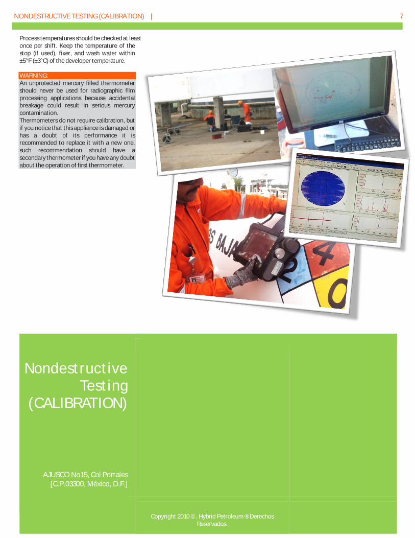
Process temperatures should be checked at least once per shift. Keep the temperature of the stop (if used), fixer, and wash water within ±5°F (±3°C) of the developer temperature. WARNING: An unprotected mercury filled thermometer should never be used for radiographic film processing applications because accidental breakage could result in serious mercury contamination. Thermometers do not require calibration, but if you notice that this appliance is damaged or has a doubt of its performance it is recommended to replace it with a new one, such recommendation should have a secondary thermometer if you have any doubt about the operation of first thermometer.
Nondestructive
Testing (CALIBRATION)
AJUSCO No15, Col Portales [C.P.03300, México, D.F.]
Copyright 2010 ©, Hybrid Petroleum ® Derechos
Reservados.