
Nondestructive Evaluation Methods for Characterization of ...
82
NTIAC88-1 - NONDESTRUCTIVE EVALUATION METHODS FOR CHARACTERIZATION OF CORROSION A ------ STATE-OF-THEI-ART REVIEW w. SwRI Project 17-7958-508 VI by I R.E. Beissner A.S. Birring SOUTHWEST RESEARCH INSTITUTE San Antonio, Texas______ ELECTE L4M It IMD 1December 18 L NONDESTRUCTIVE TESTING INFORMATION ANALYSIS CENTER Approved for public release; distribution unlimited
Transcript of Nondestructive Evaluation Methods for Characterization of ...

NTIAC88-1 -
NONDESTRUCTIVE EVALUATION METHODS FOR
CHARACTERIZATION OF CORROSION
A
------ STATE-OF-THEI-ART REVIEW
w. SwRI Project 17-7958-508
VI by
I R.E. BeissnerA.S. Birring
SOUTHWEST RESEARCH INSTITUTESan Antonio, Texas______
ELECTEL4M It IMD
1December 18
L NONDESTRUCTIVE TESTING INFORMATION ANALYSIS CENTER
Approved for public release; distribution unlimited

UNCLASSIFIEDECURITY CLASSiFICATION OF THIS PAGE
i IForm rved
REPORT DOCUMENTATION PAGE I OMBNo. 0704-0188
la. REPORT SECURITY CLASSIFICATION lb. RESTRICTIVE MARKINGSS Unc las s ified
2a. SECURITY CLASSIFICATION AUTHORITY 3. DISTRIBUTION /AVAILABILITY OF REPORT
Approved for nublic release;2b. DECLASSiFICATION IDOWNGRAOING SCHEDULE distribution is unlimited
4. PERFORMING ORGANIZATION REPORT NUMBER(S) S. MONITORING ORGANIZATION REPORT NUMBER(S)
NTIAC-88-16a. NAME OF PERFORMING ORGANIZATION 6b. OFFICE SYMBOL 7a. NAME OF MONITORING ORGANIZATION
NTIAC (If applicable) Office of the Undersecretary of DefenseSouthwest Research Institute Research and Engineering
6C. ADDRESS (City, State, and ZIP Code) 7 a. ADDRESS (City, State, and ZIP Code)
P.O. Drawer 28510
San Antonio, TX 78284 Washington, DC 20301
8a. NAME OF FUNDING /SPONSORING 8b. OFFICE SYMBOL 9. PROCUREMENT INSTRUMENT IDENTIFICATION NUMBER
ORGANIZATION (If applicable) DL900-84-C-09l0S Defense Logistics Agency DTIC-DF
I 8c. ADDRESS (City, State, and ZIP Code) 10. SOURCE OF FUNDING NUMBERS
PROGRAM PROJECT TASK WORK UNITCameron Station ELEMENT NO. NO. NO. ACCESSION NO.Alexandria, VA 22304 1___ __ __ _
* 11. TITLE (Include Security Classfication)
Nondestructive Evaluation Methods for Characterization of Corrosion
12. PERSONAL AUTHOR(S)
R.E. Beissner and A.S. Birring
1 3a. TYPE OF REPORT 13b. TIME COVERED 14. DATE OF REPORT ( Year, Month, Day) 15S. PAGE COUNTState-of-the-Art FROM 9/87 TO 9/88 December 1988 78
16. SUPPLEMENTARY NOTATION
17. COSATI CODES . SUBJECT TERMS (Continue on reverse if necessary and identify by block number)FIELD GROUP SUB-GROUP Nondestructive Testing X-Ray Radiographic Testing/
) Eddy Current Cor rosion
Liquid Penetrant Electrochemical
ABSTRACT (Continue on reverse If necessary and identify by block number)
Corrosion is an industry-wide maintenance problem that has been rapidly expanding with thej growth in aging structural components. The question now is whether to replace a structuralcomponent or to inspect and repair. Replacement can be performed on low-cost items such asland vehicles; but inspection and repair have been the preferred route for high-cost itemssuch as offshore platforms, aircraft, ships, and missiles. While the inspection and repairapproach is justified, the reliability of certain nondestructive evaluation (NDE) inspectionsis questionable. Methods for detection of hidden corrosion, measurement of material degrada-I tion due to corrosion, and quantification of corrosion are not fully developed. The need forimproving inspection methods is, however, accelerating with the increasing inventory and ageof defense equipment and with the high cost of adding new equipment. This report \s a survey
,of the NDE methods presently being used for detection and evaluation of corrosion.! TheseI include visual, magnetic, thermographic, electrochemical, acoustic enission, eddy current,liquid penetrant, and x-ray and neutron radiographic methods. (continued on reverse)
20 DISTRIBUTION/AVAILABILITY OF ABSTRACT 21. ABSTRACT SECURITY CLASSIFICATION
IMJNCLASSIFIEDxUNLIMITED - SAME AS RPT D1TIC USERS I22a NAME OF RESPONSIBLE INDIVIDUAL 22b. TELEPHONE (Inciude Area Code) I22c. OFFICE SYMBOL
DD Form 1473, JUN 86 Previous editions are obsolete. SECURITY CLASSIFICATION OF THIS PAGEUNCLASSIFIED

BLOCK NO. 19 CONTINUED
Their advantages and limitations are part of the discussions. In addition, the reportaddresses the corrosion problems of the United States Army, Air Force, and Navy. Includedwith these problems are presently applied NDE methods, where appropriate, and identifica-tion of the new methods if conventional methods are not applicable.
I..
r
L
laoession For
NTIS GRA&I U'DTIC TAB CUnannounced Q rJustribeatlon-
. U Availability Codes
Avail and/orDist Spe4cial
I~iKL
- m m m m m l l l m l

This document was prepared by the Nondestructive Testing Information Analysis Center (NTIAC).Southwest Research Institute, 6220 Culebra Road, San Antonio, Texas 78284. NTIAC is a full serviceinformation analysis center sponsored by the U.S. Department of Defense, serving the information needsof the Department of Defense, other U.S. Government agencies, and the private sector in the field of IFnondestructive testing.
NTIAC is operated under Contract DLA900-84-C-0910 with the Defense Logistics Agency. Technical raspects of NTIAC operations are monitored by the Office of the Undersecretary of Defense, Research, iand Engineering.
a
[.
[
This document was prepared under the sponsorhsip of the U.S. Department of Defense. Neither the UnitedStates Government nor any person acting on behalf of the United States Government assumes any liabilityresulting from the use or publication of the Information contained in this document or warrants that suchuse or publication of the information contained in this document will be free from privately owned rights.
Approved for public release, distribution unlimited.All rights re-erved. This document, or parts thereof, may not be reproduced in any form without writtenpermission of the Nondestructive Testing Information Analysis Center. [
L
NTIAC-88-1,I
NONDESTRUCTIVE EVALUATION METHODS FOR
CHARACTERIZATION OF CORROSIONI
ISTATE-OF-THE-ART REVIEW
ISwRI Project 17-7958-508
by
R.E. BeissnerA.S. Birring
SOUTHWEST RESEARCH INSTITUTE
San Antonio, Texas
December 1988
NONDESTRUCTIVE TESTING INFORMATION ANALYSIS CENTER
Approved for public release; distribution unlimited
IJ

ABSTRACTr
Corrosion is an industry-wide maintenance increasing inventory and age of defense
problem that has been rapidly expanding with equipment and with the high cost of addingthe growth in aging structural components. new equipment.The question now is whether to replace astructural component or to inspect and repair. This report is a survey of the NDE methodsReplacement can be performed on low-cost presently being used for detection and evalu-items such as land vehicles; but inspection and ation of corrosion. These include visual, mag-repair have been the preferred route for high- netic, thermographic, electrochemical, acousticcost items such as offshore platforms, aircraft, emission, eddy current, liquid penetrant, andships, and missiles. While the inspection and x-ray and neutron radiographic methods.repair approach is justified, the reliability of Their advantages and limitations are part ofcertain nondestructive evaluation (NDE) the discussions. In addition, the report ad-inspections is questionable. Methods for dresses the corrosion problems of the Uniteddetection of hidden corrosion, measurement States Army, Air Force, and Navy. Includedof material degradation due to corrosion, and with these problems are presently appliedquantification of corrosion are not fully NDE methods, where appropriate, and identi-developed. The need for improving inspection fication of the new methods if conventionalmethods is, however, accelerating with the methods are not applicable.
I '1*,
II
UIU
I i

U TABLE OF CONTENTS
Page
A BSTRA CT ..................................................... ii
I I. INTRODUCTION ........................................... . . -1
g II. CHARACTERISTICS OF CORROSION .......................... 2-1
A. Corrosion M echanisms .................................... 2-1
1. O verview ........................................... 2-12. Electrochemical Corrosion Processes ...................... 2-2
3 B. Corrosion Damage ....................................... 2-4
1. Overview ........................................... 242. Localized Corrosion ................................... 2-53. Environmental Cracking ................................ 2-64. Property Degradation .................................. 2-6
3 C. Corrosion Detection and Measurement ........................ 2-7
III. NONDESTRUCTIVE TEST METHODS FOR CORROSION ASSESSMENT3 DETECTION ............................................... 3-1
A. Acoustic Emissions ....................................... 3-1
1. Detection of Surface Corrosion .......................... 3-22. Pitting Corrosion ..................................... 3-43. Cracking ........................................... 3-43 4. M aterial Degradation .................................. 3-6
B. Eddy Current ........................................... 3-7
3 1. General Applications of Eddy Current Techniques ............ 3-72. Crack Detection ...................................... 3-83. Pit D etection ........................................ 3-04. M aterial Loss ....................................... 3-95. M aterial Properties ................................... 3-106. Other Applications .................................... 3-11
I C. Electrochemical Corrosion Monitoring Techniques ................ 3-12
1. Electrical Resistance Probe ............................. 3-122. Resistivity and Potential Surveys ......................... 3-123. Linear Polarization ................................... 3-124. AC Impedance Methods ............................... 3-13
Iii

U TABLE OF CONTENTS (Cont'd)
SPRae
D. Liquid Penetrant ........................................... 3-14E. Magnetic Methods .......................................... 3-15F. Radiography and Radiation Gauging ............................. 3-16G. Thermography ............................................. 3-19H. Ultrasonics ............................................... 3-20
1. Surface Corrosion ....................................... 3-212. Pitting Corrosion ....................................... 3-213. Cracking ............................................. 3-24U4. Material Degradation .................................... 3-25
3. Visual Inspection ........................................... 3-27
1. Surface Corrosion Inspections .............................. 3-272. Cracks ............................................... 3-27
3. Pits ................................................. 3-27IV. CORROSION DETECTION NEEDS ............................... 4-1
IA. Army Corrosion Problem.....................................4-2B. Air Force Corrosion Problems ................................. 4-5C. Navy Corrosion Problems .................................... 4-10D . C n lso s .......................4 1
. CoERNCSn...............................................4-16
APPENDIX A - Scope and Language of Corrosion
Ui

I LIST OF FIGURES
2-1 An Electrochemical Cell .................................... 2-12-2 Types of Corrosion Damage ................................. 2-5
3-1 Schematic of AE Sources During Corrosion, Stress CorrosionCracking, and Corrosion Fatigue Processes ...................... 3-3
3-2 Acoustic Emission Counts Recorded While Heating Corrodedand Uncorroded Specimens ...................... ........... 3-3
3-3 AE Cumulative Event Count and Energy During the SCC Test ....... 3-53-4 Relationship Between Stress-Intensity Factor Range and
AE Activity: (a) AE Count Rate, (b) AE Energy Rate(Solution-Treated Case) .................................... 3-6
3-5 Comparison of Neutron Radiography with X-Radiography ........... 3-183-6 Thickness Measurement Method .............................. 3-223-7 Measurement Error for Commercially Available Thickness Gauges .... 3-223-8 Thickness Measurement of Corroded Plate Using Conventional
Ultrasonic M ethod ........................................ 3-233-9 Sound Reflection at a Pitting Hole ............................ 3-243-10 Focused Transducer Concept ................................ 3-263-11 Contact Ultrasonic CRT Responses at 10 MHz .................... 3-263-12 Backscattering Measurements ................................ 3-27
4-1 "Marine" Corrosion Environments in the United States ............. 4-34-2 Stabilator Corrosion-Prone and Critical Items/Areas ............... 4-64-3 Locations of Concentration of Corrosion on the Under
Section of the Aircraft Body (F-5A) ........................... 4-84of Concentration of Corrosion on the Center and
Aft Section of the Aircraft Body (F-5A) ........................ 4-84-5 Stress Corrosion Crack in the H-Link Connected to the
Landing Gear Strut, Which Was Made Visible Using aFluorescent Penetrant ............ ......................... 4-9
4-6 Identification of Inspection Zones - H-46 ....................... 4-114-7 Stabilator Main-Box Upper Skin, and Lower Skin .................. 4-124-8 Stabilator Main-Box Upper Skin, Lower Skin, and Rib .............. 4-13
v

I LIST OF TABLES
5 Table Pne
2-1 Galvanic Series for Metals and Alloys in Seawater ................. 2-3
3-1 Principal Processes of Corrosion and Their AE Detectability ......... 3-23-2 Application of Ultrasonic Techniques to Measure Remaining3 Thickness on Samples Affected by Surface Corrosion ............... 3-23
4-1 Effects of Corrosion on Avionic Components .................... 4-44-2 Corrosion Detection Assessment .............................. 4-74-3 Cost of Naval Aircraft Corrosion .............................. 4-114-4 Corrosion Examples and NDE Methods Applied .................. 4-14
vIIIU
IIIII
I- mmima iimim i n ani i

I
I I. INTRODUCTION
3 Corrosion has been defined as the degrada- important role in this effort, mostly bytion of a material or its properties because of providing detection of the early signs ofa reaction with its environment (1). Within corrosion so that corrective action can bethe scope of this definition, degradation by taken before damage becomes severe. As thecorrosion, or corrosion damage, can take many cost of repair or replacement continues toforms. The most common are localized dam- increase, demands on NDE, particularly forage such as pitting of a surface, generalized early detection of corrosion, also will increase.attack where a more or less uniform loss of Accordingly, the purposes of this review ofmaterial occurs over a large surface area, NDE of corrosion are to survey the needs forenvironmental cracking in which the combined NDE techniques, to present the state of theeffects of corrosion and stress can lead to early art in meeting those needs, and to highlightfailure, and some ferms of property degrada- methods in the research stage that may provetion such as the preferential loss of an alloying useful in practical corrosion NDE.agent. The mechanisms by which corrosiondamage occurs are also varied, but can be The second section of this review is a surveyclassified generally as electrochemical, chemi- of corrosion mechanisms, with emphasis oncal, or physical. those affecting metals. Also included in this
section are a description of the nature ofAlthough no generally accepted norm is corrosion damage and a summary of itsavailable by which the economic impact of physical factors for use in corrosion detection.corrosion can be measured, one comprehen- The third section is a review of corrosion NDEsive survey (2) places the value at billions of methods, including those in use and underdollars per year in the United States alone, development. Section IV addresses corrosionRecognition of the severity of the problem by detection needs of the U.S. Army, Air Force,various industries and governmental agencies and Navy. The final section contains thehas led to a significant effort within the past references, and a glossary of corrosion-related50 years to prevent and control corrosion. terms is presented in Appendix A.Nondestructive evaluation (NDE) plays an
'IIUIiI1 1-1
3 II. CHARACTERISTICS OF CORROSION
3 A. Corrosion Mechanisms
1. Overview
Corrosion damage to metals is usual- '- 0ly an electrochemical process. This type of 0corrosion proceeds by means of chemical reac-tions involving charge transfer among theatomic constituents of the system. Damageoccurs at a part of the system called the anode Anode Cao
Anod e 0 Cathodewhere metal atoms lose electrons as they move L.__.Jfrom the surface of the metal into an electro-lytic solution in contact with the surface. Thiselectron loss mechanism, called oxidation, is (a)characteristic of an anodic region where metalloss occurs. At another part of the system,called the cathode, charge transfer occurs inthe opposite direction; i.e., positive ions in the 4 e Fe++electrolyte recombine with electron-, from themetallic cathode to form neutral species. Theprocess of electron capture by positive ions at e
the cathode is called reduction. Although the Fe++reduction mechanism does not result in metal 6..
loss, certain forms of damage such as hydrogenembrittlement can occur in cathodic regions.
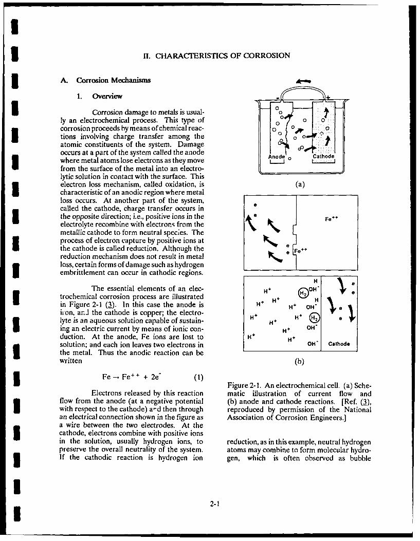
The essential elements of an elec- H + OH'trochemical corrosion process are illustrated H+ Hin Figure 2-1 (3). In this case the anode is H H OH'hnon, ar.i the cathode is copper; the electro- H* Hlyte is an aqueous solution capable of sustain- H Ging an electric current by means of ionic con- H4 OH'duction. At the anode, Fe ions are lost to H+ H H
solution; and each ion leaves two electrons in OH" athode
the metal. Thus the anodic reaction can bewritten (b)
Fe --,Fe+ + 2e- (1)e FFigure 2-1. An electrochemical cell. (a) Sche-
Electrons released by this reaction matic illustration of current flow andflow from the anode (at a negative potential (b) anode and cathode reactions. [Ref. (3),with respect to the cathode) ard then through reproduced by permission of the Nationalan electrical connection shown in the figure as Association of Corrosion Engineers.]
a wire between the two electrodes. At theIcathode, electrons combine with positive ionsin the solution, usually hydrogen ions, to reduction, as in this example, neutral hydrogenpreserve the overall neutrality of the system. atoms may combine to form molecular hydro-3 If the cathodic reaction is hydrogen ion gen, which is often observed as bubble
I~2-I
I
3 formation on the cathode. Thus the cathodic 2. Electrochemical Corrosionreaction is Processes
2H + + 2e" -. H2 (gas) (2) As just noted, one factor associatedwith electrochemical corrosion is the existence
The overall reaction can be written as of a potential difference between two surfaces.This difference could be caused by an external
Fe + 2H -. Fe + + H2 (3) source, but is more often a reci:lt of a funda-mental characteristic of a material in a given
This very simple example of a corro- electrolytic environment. One result of thesion cell illustrates the essential features of oxidation and reduction processes occurringelectrochemical corrosion. These are (1) the at a metal surface is the alteration of the elec-existence of an electrochemical potential dif- trical potential of the metal. Because chargeference between two metal surfaces, (2) the transfer rates differ for different combinationspresence of an electrolyte in contact with both of metal and electrolyte, different equilibriumsurfaces, and (3) an electrical connection to potentials exist for each metal-electrolyte pair.complete the circuit. The electrochemical Thus, potential difference occurs between twocorrosion cell can, however, take many forms dissimilar metals in an electrolytic solution.other than that illustrated in the figure; these This natural potential difference provides thewill be described later when electrochemical driving force in most instances of electro-U corrosion is considered in more detail, chemical corrosion.
Chemical corrosion differs from the The anodic or cathodic nature ofelectrochemical process through the absence two dissimilar metals in a given electrolyteof separate oxidation and reduction reactions. can be determined by consulting a table calledConsider, for example, the reaction of silver the galvanic series for metals in that electro-nitrate with sodium chloride to form silver lyte. As an example, Table 2-1 shows thechloride and sodium nitrate: galvanic series for metals in seawater. The
metals are arranged in order of increasingAgNO 3 + NaC! - AgCI + NaNO 3 (4) potential; i.e., a given metal is more negative
(anodic) than those that appear below it inIn this case, positive silver ions combine di- the table. For example, if zinc and copperrectly with negative chlorine ions to form the are the two electrodes in a seawater solution,silver chloride precipitate; no separate oxida- then the zinc electrode will be the anode andtion reactions occur for silver or reduction copper will be the cathode. If, on the otherreactions for chlorine, hand, zinc and magnesium were used, then
magnesium, being more negative than zinc,Finally, a third process called physi- would be the anode; and the zinc electrode
cal corrosion produces corrosion without would be the cathode. Because metal losschemical reactions. In physical corrosion deg- occurs at the anode, knowledge of the galvanicradation is caused by (1) a mechanical process series for a particular electrolytic environmentsuch as impingement of particles carried by a can be valuable in deciding where to look forflowing liquid on a surface, (2) cavitation evidence of electrochemical corrosion damage.corrosion caused by the sudden formation andcollapse of bubbles on a surface, and (3) fret- If two different metals are broughtting damage associated with the abiasive into contact in an electrolytic solution, theinteraction of two surfaces rubbing against one resulting system is the familiar galvanic cell.another. It often happens that physical The metal nearer the top of the galvanic seriescorrosion leads to enhanced electrochemical forms the anode; the o:her metal is thecorrosion by removing or damaging surface cathode, and the electrical connection neededfilms or depositions of corrosion products that to complete the circuit is provided by the con-tend to protect a surface from its corrosive tact between the two metals. The rate ofenvironment. corrosion activity is governed by the relative
II 2-2
aI i

3 Table 2-1
GALVANIC SERIES FOR METALS AND ALLOYS IN SEAWATERIMagnesium 76-Ni-16- Cr-7 Fe Alloy (Active)Magnesium Alloys 60 Ni-30 Mo-6 Fe-1 MnZinc Yellow BrassGalvanized Steel Admiralty BrassAluminum 1100 Red BrassAluminum 2024 CopperMild Steel Silicon BronzeWrought Iron 70:30 Cupro NickelCast Iron G-Bronze13-Percent Chromium Stainless-Steel Silver Solder
Type 410 (Active) Nickel (Passive)18-8 Stainless-Steel Type 304 (Active) 76 Ni-16 Cr-7 Fe Alloy (Passive)Lead-Tin Solders 13 Percent Chromium Stainless-SteelLead Type 304 (Passive)Tin SilverMuntz Metal GraphiteManganese Bronze GoldNaval Brass Platinum
i Nickel (Active)
positions of the metals in the table, with the active (anodic) region will occur. Thisgreater table position differences correspond- might happen if the surface layer is removeding to more activity. As in all electrochemi- or damaged in one region, or is preventedcal corrosion processes, damage is observed from forming by local environmental condi-as metal loss at the anode, accompanied by the tions. Several other situations also causeformation of corrosion-product deposits on corrosion cells to form on a single metal sur-one or both surfaces. face, with one part of the surface being anodic
and another part being cathodic.Under certain environmental condi-
tions, some metals exhibit a phenomenon Although passivity is usually treatedknown as passivity. When this happens, a as a separate topic, the formation of a passiv-very thin film is formed on the metal surface; ating film can be considered as a special caseand this film acts as a barrier to further corro- of a more general phenomenon known assion, sometimes reducing the corrosion rate by polarization. Generally, polarization refersorders of magnitude. In terms of the galvanic to any effect that tends to alter the corrosionseries, the formation of a passivating layer rate. For example, in a weak acid the con-makes the metal more cathodic, thus lowering centration of hydrogen ions becomes depletedits position in the activity series. This is as the reaction proceeds, resulting in aindicated in Table 2-1 by the terms "active" decrease in the hydrogen ion reduction rateand "passive" after certain entries, at the cathode. This, in turn, leads to a slow-
ing down of corrosion activity. Another possi-If passivity is present on one part of bility is that electron capture at the cathode
a metal surface and not on another, there will might be inhibited by some other cathodicbe a potential difference between the active reaction, again resulting in a decrease in theand passive regions, as indicated by a galvanic corrosion rate. In either case, the process byseries like that in Table 2-1; and corrosion of which the corrosion rate is diminished by
2-3I

3 cathodic reactions is called cathodic polar- solution exist at one part of an anodic surfaceization. Similarly, processes limiting the corro- with respect to another. In the region withsion rate through reactions at the anode are the higher metal ion concentration, it is ener-referred to as anodic polarization processes. getically more difficult to create more metalThe overall corrosion rate is therefore con- ions in solution than is the case where thetrolled by the combined effects of cathodic concentration is lower. The high concentrationand anodic polarization, region then becomes cathodic with respect to
the low concentration region, leading to whatAn agent that tends to reduce polar- is called a metal ion concentration cell. Such
ization and thus enhance corrosion is known cells might form where velocity gradients in aas a depolarizer. The most common cathodic fluid move past the surface. Metal ions aredepolarizer is oxygen, which can take the place swept away faster where the velocity is greater,of hydrogen ions in removing electrons from and a corrosion cell is produced in which the3 the cathode. The reaction is region with higher fluid velocity is anodic.
02 + 4e- + 2H 20 --. 40H- (5) Finally, in this survey of electro-chemical corrosion mechanisms, another1 If cathodic polarization is caused by process can be important when ions of the
hydrogen ion depletion and if cathodic polari- more noble metals (those near the bottom ofzation is the controlling factor, the corrosion the galvanic series) are in solution in contactrate will be determined by the availability of with a surface of a more active metal (oneoxygen. This explains the common observa- near the top of the series). An example mighttion that corrosion rates are usually greater in be copper ions in solution contacting an alumi-aerated solutions than in solutions containing num plate. In this case the copper tends tolittle oxygen. deposit, or plate out, on the aluminum, creat-
ing a small island of copper on the surface.Variations in oxygen concentration Because of the rather large potential differ-
from one part of a surface to another can lead ence between the two metals in this case (seeto the formation of corrosion cells, in much Table 2-1), the result is a very active galvanicthe same way as variations in passivity. In cell, with the copper deposit being the cathoderegions when the oxygen concentration is high, and the aluminum substrate forming theelectrons are removed more rapidly from the anode.metal than in regions where the concentrationis lower. This makes regions of high oxygen B. Corrosion Damageconcentration more cathodic than regions oflow concentration, creating a potential differ- 1. Overviewence between the regions. The end result isa special kind of corrosion cell, called an Figure 2-2 is a schematic illustra-oxygen concentration cell, in which the region tion of several forms of corrosion damage (4).of low oxygen concentration is the anode and The simplest of these is general attack whenthe region of higher concentration is the a more or less uniform loss of material occurscathode. Oxygen concentration cells are quite over a surface. In most cases, general attackcommon, and tend to occur whenever oxygen is caused by very small anodic and cathodicis prevented from reaching part of a surface, areas on the surface, which switch places assuch as in a crevice or under a surface deposit. the process continues. The end result is thatAs always, metal loss occurs at the anode, at one time or another all regions of thewhich is the hidden or covered part of the surface are anodic, and material loss over asurface in an oxygen concentration cell. sufficient length of time is approximately
uniform.Corrosion cells can also be formed3 if a higher concentration of metal ions in
2I 2-4
I

UU Original Surface - Flow
1. Ge"rlAtac" '-" 5. Velocity Phenomena Flow
1, General Attack r: .= : , .'J a rsoa. Erosion
Bubblesb. Cavitation
2. Localized Attack c. Impingement3 a. Localized Corrosion ;Load
-- Vibrb. Pitting 6. Fretting - 7.
c. Crevice Corrosion - 7. Intergranular Attackd. Poultice Corrosion 8. DealloylngaDeposition Corrosion -'
f. Filiform Corrosion
3..alvanic Attack Active NobleI-Metal Metal
U 4. Cracking Phenomena 7 7* Static~Stress
a. Stress Corrosion Crackingb. Hydrogen Embrittlementc. Liquid Metal Embritt"ement Dynamicd. Corrosion Fatigue Stress
IFigure 2-2. Types of corrosion damage. [Ref. (4), reproduced by permission of theNational Association of Corrosion Engineers.]
In discussing the NDE of corrosion, probably associated with damaged or weakit is convenient to divide the remaining forms spots in the coating.of corrosion damage into three classes depend-ing on the type of damage observed. The first Crevice corrosion is a special formis localized corrosion, which results in the of pitting occurring at crevices or cracksformation of pits or similar defects. The formed between adjacent surfaces. The corro-
second is environmental corrosion, which sion mechanism in this case is usually theincludes the corrosion-enhanced formation of formation of an oxygen concentration cell,cracks; and the third is degradation of proper- with metal loss in the crack or crevice with aties in the absence of crack or pit formation. low concentration of oxygen.
2. Localized Corrosion Poultice corrosion is similar tocrevice corrosion in that an oxygen concentra-
Many forms of localized damage are tion cell is involved. With poultice corrosion,the result of localized corrosion cells with however, the anodic region of low oxygen con-anode and cathode in close proximity on a centration is covered by some foreign material
surface. Pitting is a particular form resulting on the surface, and metal loss occurs under thefrom metal loss at a local anode and leading covering.to cavity formation. Shapes of pits varywidely; some are filled with corrosion products Filiform corrosion is still anotherwhile others are not. This form of damage is form involving oxygen concentration cells, inoften observed in metals that are coated or this case under organic or metallic coatings.otherwise protected by a surface film, and is Damage is characterized by a network of
2i 2-5

threads or filaments of corroded material stress-corrosion cracking, hydrogen embrittle-under the surface. ment, and liquid metal embrittlement.
3 Galvanic attack can also cause Stress-corrosion cracking can occurpitting of the more active of two dissimilar in a mildlvcorrosive environment under tensilemetals in contact. Depending on the relative stress that would not normally be consideredareas of the anodic and cathodic surfaces, this excessive. Metal loss is small; and the cracks,form of corrosion can lead to a more which can be either intergranular or transgran-dispersed metal loss. Thus, if the anode area ular, tend to be multiple branched. The crack-is large compared to the cathode area, damage propagation mechanism is not understood into the anode will tend to be more uniform detail, but seems to involve the combinedthan if the reverse were true. effects of electrochemical corrosion, with an
anodic region at the crack tip, and tensileIn all of the cases just described, the stress, which tends to open the crack to allow
mechanism leading to localized damage is further corrosion.electrochemical in nature. Certain physicalforms of corrosion, however, can also produce Unlike stress corrosion cracking (anlocalized damage. One of these is fretting in anodic process), hydrogen embrittlement iswhich metal is removed by the abrasive action caused by a cathodic reaction. Normally, whenof one surface moving against another. hydrogen ions are reduced at the cathode, theyVibrating machinery produces fretting, and combine to form molecules of hydrogen gasdamage is characterized by surface discolora- and leave the surface. Under some circum-tion and deep gouges or pits. stances, the formation of molecular hydrogen
is inhibited, leaving atomic hydrogen free toLiquid flowing over a surface also diffuse into the metal cathode. For uncertain
causes velocity-related damage effects. If the reasons, the presence of atomic hydrogen inflow is turbulent, erosion damage can occur a metal matrix causes severe deterioration ofand may accelerate electrochemical corrosion ductility, or hydrogen embrittlement.by the removal of protective films. Thepresence of particles in the liquid usually will Embrittlement can also be causedaccentuate erosive effects. Erosion damage is by intergranular penetration of liquid metals.often uniform, but it can also produce pitted Such reactions are very specific to thesurface areas. Other velocity-related effects embrittling agent; i.e., they occur only forare cavitation damage, caused by the forma- certain combinations of metals and liquidtion and collapse of bubbles, and impingement agents. Stainless steels, for example, are veryattack, caused by high-velocity flow producing susceptible to embrittlement by molten zinc,a pattern of localized damage with directional aluminum, or cadmium.features.
even~ totensle sch. Property Degradationi3. Environmental Cracking4.PoetDgrdin
In addition to producing defectsSome materials subjected to tensile such as pits or cracks, corrosion can also lead
stress in a specific corrosive environment are to the deterioration of material propertiessusceptible to spontaneous brittle fracture, without the presence of flaws that might beeven though such materials in a noncorrosive detectable with conventional NDE. Embrittle-environment may be quite ductile. This ment by hydrogen or a liquid metal might bephenomenon, known as environmental crack- considered property degradation. althoughing, is different from stress-assisted cracking embrittlement is usually accompanied by crack-in which a material, weakened by corrosion ing and is, therefore, associated with defectdamage, cracks under tensile load. Environ- formation. Other examples of property degra-mental cracking refers to crack formation dation are intergranular and transgranularunder the combined effects of stress and corrosion, corrosion fatigue, and dealloying.corrosion. Examples discussed here are
I~2-6

U Intergranular corrosion is a highly from gray cast iron). In this particular case,localized form of damage in which attack the damaged part may appear the same as anoccurs along a narrow path that tends to follow undamaged part; but it is porous, extremelygrain boundaries. Its cause is from a potential brittle, and easily damaged.difference developing between the grainboundary and surrounding material, which, in C. Corrosion Detection and Measurementturn, is caused by the trapping and precipita-tion of impurities at grain boundaries. The objectives of corrosion NDE are toBecause of this dependence on grain-boundary detect and measure the extent of corrosioncomposition, susceptibility to intergranular damage and/or corrosion activity. As usual inattack is strongly dependent on metallurgical NDE, emphasis in damage detection is ontreatment. In particular, the heat-affected small flaws, so that repair or replacement ofzone near a weld is a region where the parts and possibly correction of the corrosivetemperature produced during the welding environments can be accomplished at mini-process causes impurities to migrate and mum cost.become trapped at grain boundaries. Theheat-affected zone can, theretore, be suscep- Corrosion NDE is different from othertible to intergranular corrosion. applications because ar, estimate of corrosion
rate may be needed in addition to a measure-Transgranular corrosion is similar to ment of existing damage. To make a cost-
intergranular corrosion in that attack is highly effective assessment of the need for correctivelocalized and follows a narrow path through action, sometimes identifying flaws of a giventhe material. As the name implies, the paths type and size in a particular location is notin this case cut across grains with no apparent enough. Information on corrosion activity isdependence on grain-boundary direction. also needed; i.e., the rate at which damage isTransgranular corrosion is often associated occurring. Periodic repetition of an inspec-with corrosion fatigue, although intergranular tion is one means of monitoring flaw growthand sometimes both intergranular and trans- rate. This approach does, however, requiregranular corrosion are observed, accurate measurement of flaw size. Other
alternative measurement approaches moreCorrosion fatigue is a term applied directly related to corrosion rate also are avail-
to the degradation of fatigue life in a corrosive able. But regardless, the need for rate infor-environment. It is distinguished from environ- mation places additional demands on corrosionmental cracking in the sense that corrosion NDE over flaw detection alone.fatigue refers to degradation by any corrosiveenvironment and is not specific to a particular Additional differences exist betweenmechanism, while environmental cracking corrosion NDE and other applications. Cor-relates to specific metals and environments rosion products, for example, provide anand specific forms of damage. Corrosion opportunity for NDE that does not exist in afatigue is distinguished from environmental noncorrosive environment. Evaluation of thecracking by the morphology of the fractured integrity of corrosion protection systems issurface. another example of a possible NDE applica-
tion. This section provides a brief review ofDealloying, another form of the physical manifestations of corrosion useful
material-degradation, is quite different from when assessing the need for NDE.those just considered. The term refers to theselective dissolution of an alloy constituent in The detection of corrosion pits, cracks,an anodic reaction. The best-known example or wall thinning due to general attack of ais dezincification of brass, in which zinc is surface are examples of corrosion NDE prob-preferentially removed, thereby altering the lems that differ only in detail from problemschemical and mechanical properties of the encountered in other branches of NDE. Formaterial. Another example is graphitization, this reason, most of the corrosion NDEwhich is a selective removal of iron (usually examples cited in the next chapter are simply
I* 2-7

U adaptations of conventional NDE methods to effects associated with corrosion productscorrosion problems--with a few differences. could form a basis for corrosion detection.For example, if a corrosion pit is partiallyfilled with a corrosion product with nearly the Electrochemical corrosion also impliessame physical properties as the host material, the existence of an electric current and anthen detection and sizing of the flaw are more associated magnetic field. These currents and3 difficult than would be the case in the absence fields are extremely weak, and have onlyof corrosion products. The detection of recently been detected in a carefully controlledcrevice or poultice corrosion might also be laboratory environment using a SQUIDmore difficult than detection of other types of (Superconducting Quantum Interferenceflaws because the damage is hidden in a crack Device). On the other hand, electrochemicalor crevice or under a patch of material on the measurement techniques based on the analysissurface of the part. Environmental factors of DC or AC polarization data can providemight also present special difficulties, such as estimates of the corrosion current and mayin situ inspection of underwater structures. find some use in NDE as a means of measur-
ing corrosion rate.In some situations, corrosion damage can
take the form of material-property changes. An active electrochemical cell requiresEmbrittlement, for example, is usually accom- the presence of an electrolytic solution and apanied by cracking. Possibly for some cases potential difference between anodic andthe measurement of a physical quantity related cathodic regions. When it is possible to maketo ductility would be easier to implement and such measurements, electrical potential sur-be perhaps more meaningful than the detec- veys and data on the resistivity of the solutiontion of cracks. Dealloying is another such provide useful information on the possibilitymaterial-property change that could be for corrosion. Because it is usually imprac-amenable to measurement. The existence of tical to obtain such data on a sufficiently fineintergranular or transgranular corrosion or spatial grid, applications are limited to theproperty changes associated with corrosion assessment of large-scale corrosion; i.e., condi-fatigue are additional examples. tions amenable to localized cell formation are
not measured.I In principle, electrochemical corrosionalways generates corrosion products, although Finally, NDE could be applied to thethese products are not always detectable. One evaluation of corrosion protection systemsdetectable corrosion product, often by a simple such as coatings used to protect metals fromvisual inspection, is rust produced in the corro- corrosive environments. Cathodic protectionsion of products containing iron. Another is systems (electrical systems designed to reversehydrogen gas, which is often found at the the current flow from a region that is normallycathode in an electrochemical cell. Other anodic) are another example where direct orproducts and possibly physical or chemical indirect measurement of current or potential
differences could be useful.
IIII
i 2-8
I IM. NONDESTRUCTIVE TEST METHODS FOR CORROSIONASSESSMENT DETECTION
Inspection for corrosion to date has generally noise level. The proof test is different frombeen performed by either directly applying on-line monitoring, as it employs applicationthe conventional NDE methods or applying of an additional load to produce AE. Thisafter slight modifications. In general, NDE external load forces the flaws to grow andfor corrosion has been directed toward find- produce AE. The proof test is short terming the appropriate conventional method that compared to on-line monitoring, which can gocan perform such an inspection. This fact was on for days or even years. Both tests are rele-also supported by a survey on corrosion moni- vant for detection of corrosion.toring methods performed in the U.K. (f,6).Thus, very few specific NDE methods exist for AE from corrosion can occur fromcorrosion. This section includes a spectrum of various processes. Pollock (7) summarizedthe methods applied for a range of corrosion these processes as candidates for detection byproblems. Included are both the application AE (see Table 3-1). As seen from the table,of conventional methods and discussion of three of the listed corrosion processes do notnovel methods for corrosion NDE. produce detectable emission. Electric currents
do not because moving electrons do not stressA. Acoustic Emissions the lattice. Migration of atoms during film
growth will stress the lattice and might beAcoustic emission (AE) refers to the expected to produce continuous AE; but in
generation of elastic waves in a material slow-growing films, the acoustic energy wouldcaused by its deformation under stress. Flaws be very low, and the effect has not beencan be detected using AE methods because reported to date. Dissolution of metal andflaw growth caused by stresses produces acous- active-path corrosion [in stress-corrosion crack-tic emissions. Material stress can come from ing (SCC)] are equally silent; the forcesmechanical and thermal loading, as well as involved in the passage of individual atomsfrom a variety of other means. into solution are negligible at ordinary rates
* of dissolution.AE from materials is generally one of
two types. The first is low-level and almost Cracking of the corrosion-product filmcontinuous. This AE, similar to background will produce detectable emission. The energynoise, can be from plastic deformations, micro- source is the elastic stress field that developsstructural changes, or a chemical reaction during film growth or temperature change andrelated to corrosion. Low-level AE can also releases during sudden cracking, spalling, orbe produced by flaking or removal of corrosion exfoliation. Thick, brittle, tenacious films, inproducts from a surface. High-level signals in general, produce higher amplitude emissionsthe form of bursts are generally associated than thin, soft, or weak films; emission maywith sudden release of energy. This can be not be detectable for the latter type.due to such factors as growth of discrete flawslike cracks, the burst of bubbles, and The evolution of gas is a recognizedcavitation, source of low-amplitude emision during corro-
sion in liquid media. The energy associatedThe most common tests for AE are on- with a bubble is converted into kinetic energy
line monitoring and proof. On-line monitor- when the bubble bursts. Studies done bying is a passive method where AE is recorded Scott (8), have shown, however, that AE isfor a long time. In this case, the structure is associated with the actual formation of theunder a constant load, such as pipes transport- bubble and not from bursting in certain cases.ing gases at constant pressure or a certain Hydrogen-induced microcracking produces achemical reaction. A flaw is flagged if a large number of level emissions caused bychange occurs in AE from the background finely distributed microcracking, while mere
I* 3-1

ITable 3-1
PRINCIPAL PROCESSES OF CORROSION AND THEIR AE DETECTABILITY[Ref. (7), reproduced by permission of the American Society for Testing and Materials]
IPROCESS DETECTABLE BY AE?
Passage of Electric Current NoDissolution of Metal NoFilm Formation NoFilm Cracking Depends on ThicknessEvolution of Gas Yes-Low AmplitudeHydrogen Migration/Microcracking Yes-Low AmplitudeSCC-Active Path No (Except Plastic Zone)SCC-Discontinuous Cracking Yes-High AmplitudeHydrogen Cracking Yes-High Amplitude
SCC = Stress Corrosion Cracking
Imovement of hydrogen atoms is not expected 1. Detection of Surface CorrosionI to produce detectable AE.o pDetection
of surface corrosion byStress-corrosion cracking and corrosion AE has been performed for a variety of appli-
fatigue will all produce high-level AE. The cations. These methods detect corrosion byenergy of AE during crack growth is drawn detecting AE generated from the breaking offrom the stress field around the crack, which corrosive films or products, chemical reaction,relaxes momentarily as the crack jumps for- or bursting of bubbles.ward. The stress field is created by the exter-nal forces in combination with internal pres- Detection of corrosion in aircraftsure if hydrogen is involved. Yuyama (2) has honeycomb structures has been performed atschematically shown the various corrosion McClellan Air Force Base (10). The test wasprocesses that produce AE (see Figure 3-1). conducted by heating a local area of the struc-
ture and listening for the AE produced byAE signals are generated mainly by crack evolution of hydrogen gas or steam. AE from
initiation and growth induced by SCC or hy- the corroded areas was only detectable for wetdrogen embrittlement. However, the evolu- areas and not from dry ones.tion of hydrogen (H2) gas via cathodic reac-tion in acid solutions and the breakdown of Birring (11) has performed an AEthick-surface oxide film formed under certain test on corroded parts obtained from ancircumstances are also important sources of aircraft. AE activity monitored during appli-significant AE. In addition, the fracture or cation of heat showed that corroded partsdecohesion of phases such as precipitates, produced 15 times the amount of AE countssecond-phase particles, and nonmetallic inclu- compared to the noncorroded parts (seesions and the twinning in the plastic zone of Figure 3-2). The AE method was unsuccess-a crack are expected to produce detectable ful on parts with no deposits of corrosionAE. On the other hand, dissolution of metals products. The test concluded that the AE wascan hardly be detected by AE technique. produced by the breakage of the corrosion film
I* 3-2

Dissolution ofMetal H Gas Evolution AE Breakdown of
AE AE 2 nThick Oxide Film_\M-M"+- H+e'--I/EH-1 A I E - I
Anodic Cathodic \ / .
Reaction Reaction -1/2H 21AE Dissolution of Metal
Fracture or A CDecoheson / AE SCC Crack Propagation
of Precipitation - . AE Plastic DeformationAE FSlip Deformation
I. _L win DeformationMartensitic Transformation
Figure 3-1. Schematic of AE sources during corrosion, stress corrosion crack-ing, and corrosion fatigue processes [Ref. (2), reproduced by permission of theAmerican Society for Testing and Materials]I
500
400- Corroded
I 300
Ww
I 200
100. Uncorroded
0 1 2 3Time (mins)
Figure 3-2. Acoustic emission counts recorded while heating corroded anduncorroded specimens. The acoustic emission counts on the corroded specimenwere more than 14 times greater than those on the uncorroded specimens (1I).
Ii 3-3

I
and that AE testing would detect the breakage 2. Pitting Corrosionof corrosion film during thermal expansion.
Detection of pitting corrosion byScott (a) has conducted studies to AE has been very limited until recently. Parry
monitor AE from a chemical reaction. His (6) performed laboratory tests to detect AEwork showed that aluminum partly emerged from corroded pipes and later verified hisin a solution of sodium hydroxide produced findings with results from ultrasonics andAE. The formation of bubbles on the metallic visual observations. Difficulties were experi-surface were identified as one of the major enced in detection, locations, and grading ofsources. He states, however, that not all the most severe corrosion pits where a pipe-chemical reactions can be detected by using line has general heavy corrosion over longAE, although AE is produced by most of the lengths of its surface. Such general corrosionreactions involving aircraft alloys and likely produces emissions over the entire length ofcorrodants with the notable exception of rust the line, thus increasing the background levelformation. of the data.
Fenn and Condello (.2) showed that AE from pitting is believed to beAE can be used to distinguish among various created from secondary effects of corrosion;types of films formed by corrosion. Differ- i.e., scale and oxide cracking under stressences in AE energy output and the spectral imposed at a level exceeding that at which thecontent were discovered during the fracture of oxides and scales were formed. Parry (6)different types of film. They suggest that, by found that emissions were produced as theidentifying different species of oxides, films stress levels in the pipe exceeded the normalwould determine the different corrosion mech- operating stress by 10 to 20 percent and thatanisms. very few emissions were produced above this
range.Rettig and Felsen (3) monitored
AE produced from a reaction of aluminum 3. Crackingwire within salt water. They concluded thatfailure prediction can be made empirically The literature currently availablefrom the AE counts, rate, cumulative counts, contains much information about the applica-and pulse amplitude. In another study, tion of AE for detection of SCC and corrosionMansfeld and Stocker (14) demonstrated that fatigue. Yuyama (9) has studied the initiationAE count rate accurately reflected the corro- and growth of SCC. A double-cantilever beamsion behavior of aluminum alloys. (DCB) with an artificial crevice was immersed
in 3-percent NaCl, and the AE activity was
Yuyama and coworkers (15) found monitored. The tests showed that the AEa relationship between a polarization curve energy was relatively low until after 10 hours;and the AE count in stainless steels. Their then it suddenly increased by a large amount.results showed that AE is detected only when AE energy was found in the middle of thethe reductive breakdown of passive film occurs measured zone; namely, the crack tip. It wasand hydrogen gas evolves on the specimen thus concluded that the high-amplitude AE insurface. No AE was detected when the oxida- Figure 3-3 caused the sudden increase of thetion breakdown occurred and the metal AE energy at 10 hours and that the SCC initi-dissolved into solution. ated at that time.
III
3-4I

3 in 308K 3% NaCI
-0.1 Ki=1 5.5MPa.m 1/2
200
-00 W >
.AE Counts AE Energy V01 0 20 30 40 50 60 70
Tine I ks
Figure 3-3. AE cumulative event count and energy during the SCC test [Ref. (2),reproduced by permission of the American Society for Testing and Materials]
Cox (17) reported that emissions used to detect cracking with a depth range offrom a zincalloy-2 specimen of DCB type can 10 to 100 microns.be divided into (1) a continuous emission dueto plastic deformation at the crack tip and Mehdizadeh (2L) has monitored(2) a high-amplitude, burst-type signal because the progress of corrosion fatigue (CF) damageof the propagation of the crack. In most cases, of quenched and tempered carbon/manganese
as also observed by Yuyama, an initiation (C/Mn) steel in 3-percent NaCI solution byperiod occurs with low AE activity. AE generated during corrosion fatigue test and
periodic proof loadings. The result showedOkada et al. (18) carried out SCC that periodic proof testing combined with AE
tests for Type 304 stainless steel in 5N H2SO 4 monitoring could be a sensitive method for+ 5M NaCI at 25 degrees C and for ferritic assessing the progress of corrosion damage.and high-strength martensitic stainless steels This method can establish the initiation ofin boiling magnesium chloride (MgCI2) aque- incipient fatigue cracks after as little as 5 per-ous solution at 143 degrees C. They measured cent of the total fatigue life. A qualitativeAE and changes of the electrical resistance or method based on the saturation of AE duringdisplacement of cantilever beam specimens. period proof loading was used to determineThe results showed that the significant AE the remaining fatigue life, and this schemecould not be detected during the SCC propa- predicted the remaining fatigue life up togation of Type 304 and ferritic stainless steels; 70 percent of the actual values.in which case, active-path corrosion (APC) wasdominant as the SCC process. The high AE Yuyama et al. (5,21) have madeactivity, in contrast, was observed during the systematic studies of AE produced during CFSCC of high-strength martensitic stainless of a 304 austenitic stainless steel potentiostat-steel; and, in this case, hydrogen embrittle- ically polarized in I N H2 S0 4 + 0.5 M NaCIment was determined to have caused the SCC. or I N H 2SO 4 solutions, using compact tension
specimens. The crack growth rates at -0.8V,Fiest (1.9) has applied AE to find E4o and-0.28Vwereacceleratedsignificantly
detection of intergranular cracking in gas- compared with those observed in air orturbine blades. Such cracks can be significant + 0.01V (noncorrosive environments) when AKwhen present in the area of the fir-tree is less than about 37 MPa m 1/2 and where thegrooves and the blade root. AE was produced transition of the deformation patterns in thefrom the microcracks by applying thermal- crack-tip plastic zone from a hinge type takesshock loading. The root area of the blade was place and through-thickness yielding is accom-heated with an induction coil and quenched. plished. Both AE cumulative event counts andAcoustic emission signals then received were AE energy represented step-like curves, and
II 3-5

I
3 their increasing rates were found to become Culpan and Foley (2) applied AEgreater with the acceleration of crack-growth to study the selective phase corrosion attackrates. Figure 3-4 indicates the relationship in seawater of nickel aluminum bronze (NAB).between AK and AE activity. During the process, which occurs particularly
in the heat-affected zones of weld repairs,4. Material Degradation copper is redeposited at the corroded areas,
making the phenomenon extremely difficult toAcoustic emission has been very detect by conventional nondestructive testing
effectively used to detect microstructural techniques. It was considered likely that thedegradation in materials, including detection different fracture modes of sound material andof microcracking caused by hydrogen attack corroded material would result in differingand corrosion of selective phases. Jolly (2) forms of AE during deformation. Acousticapplied AE to detect hydrogen attack in a emission monitoring was performed on tensilepetrochemical plant. A large number of low- specimens of as-cast, welded, and corrodedlevel AE signals were received as the hydrogen NAB. The failed specimens were thenpenetrated in the metal and produced inter- examined using optical and scanning electrongranular damage. Triangulation was used to microscopy. Results showed significant differ-locate the source of AE. Visual observation ences in the AE behavior of the three types ofcarried out during a shutdown verified the material. These were revealed in characteris-hydrogen damage, and the AE activity was tic event counts, event amplitudes, root-mean-I absent after the pipe section was repaired. square energy outputs, and normalizeC'
I -3/2
AK 1 kg.mm
-/100 1504K/kg.mn32-
100 150I - At
0
>1A- AA 0 E=+0.1V *0o" 1 A A E = 002V 0
A1 0 0 0Aft A E = Ecorr 0 0 0
& E=-O.8V 0 E=+O1V
3 30 40 50 60 30 40 50 60
a) Stress Intensity Factor Range (b) Stress Intensity Factor Rang.3K Ox 1,2 MPa. E=2
Figure 3-4. Relationship between stress-intensity factor range and AE activity: (a) AE
count rate, (b) AE energy rate (solution-treated case) [(Ref. (L1), reproduced bypermission of the Journal of Acoustic Ernision]
Ii 3-6
I III

I amplitude analysis of the data. These differ- Hagemaier (6-28) used both ampli-ences in behavior were correlated with the tude and phase information to make quantita-varying structures of NAB and their behavior tive measurements of panel thickness. Heunder stress. inserted an aluminum taper gauge under a
probe to provide an impedance plane trajec-B. Eddy Current tory as a function of aluminum thickness.
Calibration data were obtained from panels ofEddy current testing (ET) techniques are known thickness, and these data formed the
useful in the detection and sizing of many basis for thickness determinations with panelstypes of defects related to corrosion damage. of unknown thickness. Even though the cali-In addition to its well-known applications to bration data were based on specimens ofcrack and pit detection, eddy current can be uniform thickness, the taper-gauge approachused to measure thickness changes caused by has been applied in the characterization ofcorrosion, buildup of corrosion products in localized thinning caused by corrosion pits.certain situations, and some changes in mate- The detection of cracks and foreign materialrial properties such as conductivity degrada- in multilayered structures were also discussedtion caused by intergranular corrosion. The in Hagemaier's publications.techniques and applications reviewed hereinclude examples of each of these uses of ET. A different application of the
phase/thickness relatlionship was discussed byCorrosion NDE involves a variety of ET Rowland et al. (29). They describe the
techniques ranging from simple applications remote-field, eddy current effect for theof well-established inspection procedures to inspection of multilayer, parallel-plate struc-advanced techniques based on the latest devel- tures. The remote-field technique is normallyopments in eddy current research. While used for inspection of cylindrical pipes fromsome of the examples cited here focus on the the inside (30-32). The effect, explained inmeasurement of only one flaw characteristic, detail in the referenced articles, is thesuch as the depth of a corrosion pit, others observed linear variation of phase with pipe-demonstrate the ability of a particular tech- wall thickness when transmitter and receivernique to detect and characterize more than coils are separated by about two pipe diam-one aspect of corrosion damage. Some of eters. Rowland et al. have demonstrated thatthese multi-purpose techniques are discussed the same effect is observed in parallel platefirst, followed by reviews of techniques for structures and can be used to measure platecrack and pit detection, measurements of thickness. They also discussed the uses ofmaterial thickness, and detection of material- unusual eddy current probe configurations forproperty changes. locating corrosion damage and inspecting
fastener holes.1. General Applications of Eddy
Current Techniques In one of the more advanced devel-
opments in eddy current technology, Dodd etIf the thickness of a part is on the al. (33-36) used arrays of coils, as many as 16
order of or less than the skin depth, the phase in one application, to record multifrequencylag of the eddy current probe impedance, rela- complex impedance data as a function oftive to the phase of excitation current, can be probe position. These data were used in arelated to thickness. This well-known tech- least-squares fit algorithm to determinenique was used, for example, by Bond (24,25) multiple properties such as thickness, conduc-for the detection of panel thinning and corro- tivity, and flaw size, some of which weresion pit detection in the inspection of aircraft related to corrosion damage. In general, appli-structures. Instrumentation requirements, cation of their procedure to a new test envi-sensitivity, and the practical aspects of routine ronment requires the following steps:inspection for corrosion were also discussed by (1) selection of optimum coil dimensions andBond. frequencies to maximize the signal for a
3-7
I

I property of interest, (2) experimental can provide reliable monitoring of thicknessdetermination of multifrequency impedance loss due to corrosion.data for known properties, (3) least-squaresdetermination of the coefficients in an expres- 2. Crack Detectionsion for a given property written as a poly-nomial in impedance readings, and (4) applica- While the principle of eddy currenttion of the array of known coefficients to a crack detection is the same, the nature ofleast-squares fit of data from an unknown corrosion-related cracks can be quite differentsample to determine the properties of that from, say, isolated fatigue cracks. Intergranu-sample. The method has been successfully lar stress-corrosion cracking (IGSCC), forapplied to the identification of flaws in various example, is often characterized by a multitudestructures such as multilayered plates and of multiply branched cracks in the regiontubing in the presence of welds and supporting where damage has occurred. The interactionstructure. of an eddy current field with such a region is
more complex than the interaction with aFlora (37) has used a variation of single crack of simple geometry. An eddy
Dodd's multifrequency, multiparameter tech- current scan over a region with IGSCC cannique to detect and image simulated corrosion produce an impedance plane trajectory thatpits and stress-corrosion cracks through thick more closely resembles the signal from asections of material. He used a rather large region of low conductivity than the signal from(3 inches long) electromagnet in place of a a crack. This is more likely if the damagedtransmitter coil to generate eddy currents in region is some distance from the probe, as inthe specimen. Signals were measured with a the detection of IGSCC near the inner wall ofHall probe or separate pickup coil. The use a pipe when inspected from the outside. Inter-of a large electromagnet and low operating granular corrosion without stress-related crack-frequencies resulted in deep penetration of ing can produce a similar signal, and may bethe eddy current field, and enabled detection indistinguishable from IGSCC by the eddyof flaws at depths greater than would be current method. For this reason, the detectionpossible by more conventional ET techniques. of IGSCC and similar multiply branched
cracks is sometimes considered along with thePulsed ET techniques have also been detection of intergranular corrosion as a single
investigated. Yancey (8), for example, class of eddy current detection problems. Thestudied the response of simulated cracks and detection and characterization of intergranularstepped thickness samples to pulsed excitation corrosion and stress-corrosion cracking areas a test of a system for the inspection of reviewed in another section; the detection ofirradiated fuel rods. Dodd and Deeds (39) more conventional crack-like defects is dis-also considered the use of pulsed eddy current cussed here.data in place of multifrequency data in theirmultiparameter technique. Their idea was to Some of the techniques describeduse sampled transient response data as a sig- in the preceding section, particularly those ofnature of a given property in much the same Dodd et al. (3-&, Flora (37), andway as multifrequency data are now used. Hagemaier (2-28), pertain to isolated crackThere appeared to be some advantage to the detection as well as to other aspects of cor-pulsed approach in terms of equipment rosion NDE. In fact, almost all discussion ofrequirements and ability to inspect thin-walled crack detection in the literature is concernedspecimens. either with simply shaped, isolated cracks
(whether corrosion-related or not) or withFinally, some use has been made of property changes associated with stress-cor-
the DC electrical potential drop (DC/PD) rosion cracking. One exception is the work ofmethod (40) in crack sizing and wall thinning MacLeod and Brown (4I), which was specifi-measurements. In the latter case, wall thick- cally directed at the detection of stress-cor-ness loss, as measured by the DC/PD method, rosion cracks in aluminum forgings. Most ofwas compared with direct measurements of their discussion concerned the development3 weight loss to show that the DC/PD method of an automated, motor-driven system for
1 3-8

1 wheel hub inspection. Applications to other concerned a high-speed probe drive system foraspects of aircraft inspection and maintenance heat-exchanger tube inspection. Bond andwere also reviewed. Rowland et al. were primarily concerned withwall-thickness measurements and only men-3. Pit Detection tioned the possibility of pit sizing.
Both amplitude and phase measure- As was noted before, Dodd et al.ment techniques are used in corrosion pit (3-) and Flora (7) used both amplitudedetection and sizing. With the amplitude and phase information in a multifrequency,method, one assumes that the amplitude of an least-squares determination of multipleeddy-current signal is proportional to the properties. Flora used a three-frequencydepth of a pit. The phase-sensitive technique version of this approach to obtain easily recog-assumes that remaining wall thickness can be nizable signals from simulated corrosion pitsrelated to the phase of the signal from a pit. in a steel plate covered with a nonconducting
coating. Results were presented as indicatedSmith (42) gave a very thorough corrosion depth along a scan line over fiveII discussion of the amplitude method and its simulated pits, and appeared to be in very
application to pit sizing in copper and stain- good agreement with actual flaw depths. Heless steel tubing. He showed that a good also presented images of flat-bottomed holescorrelation can be established between signal and ground areas in a plate as further evi-amplitude as a function of pit depth and dence of the capability of the method.amplitude as a function of the depth of adrilled hole. He then used drilled holes as 4. Material LossI simulated pits to study the spatial resolutionand sensitivity of his inspection system. To In corrosion monitoring applica-demonstrate the sizing capability of the tions, measurement of wall thinning due tomethod, he showed that pit-depth predictions loss of material is probably the most commonbased on drilled-hole calibration data are in use of eddy-current testing. The linear rela-good agreement with the depths of actual pits tionship between phase and wall thicknessin copper tubing as determined by metal- forms the basis for many such measurements,lographic examination. as in the work of Bond (24) and Rowland et
al. (29). In thickness gauging of cylindricalBaron et al. (43) took a different pieces like pipelines, casing, and tubing, the
approach to estimate the size of crevice cor- remote-field method (30-32) is often usedrosion pits. They started with a theoretical because it offers certain advantages if the wallprediction of the signal from a corrosion pit thickness is on the order of the skin depth ormodeled as a rectangular slot. They proposed greater (2).to use this model as a basis for relating ampli-tude data as a function of probe position to If the structure to be inspectedpit dimensions. Some experimental data for consists of more than one layer, interpretationnotches were presented, which tended to of phase-shift data becomes more complicated.corroborate the model; but no results were In the problem addressed by Hayford andreported on attempts to size actual corrosion Brown (45), the material of concern was anpits. aircraft structural member to be inspected
through an outer layer of aircraft skin. WhenApplications of phase measurements corrosion occurs on the outside surface of the
to pit-depth estimation were discussed by inner material, corrosion product buildup canNielsen (44), Bond (24), and Rowland et cause an increase in the separation of theal. (29). Nielsen used flat-bottomed holes of layers, accompanied by a decrease in the thick-various depths as calibration standards for ness of the inner (second) layer. If, on thepit-depth determination. Although mention other hand, corrosion occurs on the innerwas made of confirmation by comparison with surface of the second layer, its thicknessdata for natural flaws, no data were presented decreases; but there is no change in the airin Nielsen's article; most of his discussion gap between the layers. To further complicate
3 3-9

I matters, the air gap itself may vary from place For example, in his experimentsto place in the absence of corrosion. with cylindrical samples inside a solenoid,
Deadmore (46) found that during the initialHayford and Brown analyzed the period of exposure to a corrosive environment,
two-frequency eddy-current response of these observed inductance variations were indicativedifferent situations using a modified form of of changes in skin depth. In this particular setthe computer programs of Dodd et al. (33-36). of experiments, these were attributed toThey concluded that it was possible to distin- changes in magnetic permeability as the struc-guish cases of interest by comparing low- and ture of the near-surface region was modifiedhigh-frequency phase shifts. Experimental by the corrosion process. When the depth oftests were in qualitative agreement with the this form of corrosion damage exceeded thepredictions; but quantitative agreement was skin depth, such changes were no longerlacking, probably because of differences observed; and the rate of change of inductancebetween the experimental geometry and the was determined by material loss.configurations assumed for the calculations.
Karpov et al. (47) also studied mate-I All of the above applications were rial-property changes caused by corrosion that
concerned with loss of wall thickness in plates were, in this case, the magnetic permeabilityor pipes. Deadmore's (46) study of the vol- of corrosion products of several steels. Theyume loss of cylindrical samples exposed to a found that permeability depended more on thecorrosive environment involved a totally differ- corrosive environment than on the type ofent type of measurement. He placed his steel, and that it did not show much depen-samples inside a solenoid and measured the dence on frequency up to about 100 KHz. Ininductance change caused by the change in fill all cases studied by Karpov et al., the relativefactor as material was lost. In the limited permeability of corrosion products was lessrange of specimen diameters of interest, he than 5.found the inductance to be a linear functionIaof diameter, which led to a simple relationship Most studies of corrosion-relatedbetween volume loss and inductance change. property changes are concerned with electrical3 Comparisons with data from direct measure- conductivity degradation due to intergranularment of sample diameters showed that corro- attack (IGA) or SCC. As noted earlier, some-sion rates deduced from inductance measure- times IGA and SCC cannot be distinguishedments were in good agreement. Deadmore by the eddy-current technique because signalsused the same experimental arrangement to from individual cracks cannot be resolved andstudy material property changes occurring in both IGA and SCC are observed as a decrease
the early stages of corrosion; these investiga- in the effective conductivity of the damagedtions are discussed in the next subsection. region. This has led several workers to study
localized conductivity variations and their5. Material Properties measurement by the eddy-current technique
as a means of detecting and measuring IGADuring the early stages of corrosion or SCC.
damage, changes in near-surface propertiescan occur as a result of intergranular corro- In one such investigation, Naumovsion, formation of corrosion products, or other et al. (48) attempted to correlate the absoluteoxidation and reduction processes. In certain conductivity of an aluminum alloy with theinstances, these material-property changes can depth of intercrystalline corrosion. They werebe observed in an eddy-current test through an unable to establish such a correlation becauseaccompanying change in the conductivity or the absolute conductivity seemed to dependpermeability in the surface layer exposed to on other factors related to variability of the3 the environment. material before corrosion was initiated. On
33 3-10

I
I the other hand, they did find a good corre- Through the use of computer models andlation between depth of corrosion and the supporting experiments, he showed that achange in conductivity caused by corrosion. pancake-type coil, with its axis in the radial
direction, is better for IGA detection than aThe theoretical relationship between coil with its axis along the tube axis. Brown
depth of IGA and eddy-current response was also noted that attempts to determine theinvestigated by Prikhod'ko and Kirillova (49) depth of penetration of IGA were not success-and Wait and Gardner (LO). In both of these ful when based on either amplitude or phasecalculations, the damaged region was modeled calibrations with artificial flaws. One mightas a layer of material with conductivity and/or expect that a multifrequency method usingpermeability that differ from the values in the both amplitude and phase would fare better inundamaged material. Prikhod'ko and Kirillova IGA depth determinations. In this regard,treated the case of a two-layer plate, and ana- Dodd et al. (33) indicated that IGA waslyzed probe impedance as a function of probe included as one of the properties treated indimensions, frequency, liftoff, and the charac- applications to steam-generator tubing, butteristics of the sample. Wait and Gardner no details were given.examined the case of a hollow cylinder insidea solenoid, and presented numerical results for 6. Other Applicationscorrosion damage to both the inside and out-side surfaces as a function of frequency. The Destructive metallographic deter-authors agreed that with proper optimization mination of the thickness of zirconium oxideof the measuring system, the eddy-current corrosion films on irradiated Zircaloy-cladtechnique is capable of determination of the fuel elements is time consuming and expen-depth of IGA. sive because such operations can be performed
only in a hot cell. A much simpler measure-Prikhod'ko et al. (L1) performed ment involving the use of an eddy-current
experimental studies of various forms of probe as a proximity sensor was reported bydamage including cavities with and without Goddard and Weber (Q). They pressed aIGA, and isolated cracks and cavities. They spring-loaded probe against the nonconductingused a high-resolution differential sensor, and oxide film and calibrated it to measure thewere able to resolve individual pulses in the liftoff to the conducting Zircaloy under thesignal as the probe was scanned near the film. Measurements agreed with data fromsurface of regions with IGA. They suggested metallographic examination to within 4that different types of damage can be distin- microns.guished by noting the form of the signal
produced in a scan of the damaged surface, In addition to causing damage to athough in some cases measurements at more material, corrosion can inhibit the detectionthan one frequency may be needed. They of defects caused by other factors such asalso presented data on suggested operating fatigue. De Graf and De Rijk (4) studiedfrequencies for different depths of IGA. the deleterious effect of corrosion on the prob-
ability of detection (POD) of fatigue cracks inPhotographs and eddy current signals aluminum panels using ultrasonic, liquid pene-
for several examples of IGA and SCC in trant, and eddy-current methods. BeforeInconel tubing were given by Brown (52). He corrosion of the panels, the POD was best fordistinguished volumetric IGA where damage penetrant inspection, with eddy current beingis more or less uniform from oriented IGA the second most effective. After corrosion,where intergranular corrosion grows in partic- however, penetrant inspection results wereular directions, resulting in a crack-like poorer than eddy current, probably becausedamage that is difficult to distinguish from corrosion products inhibited penetration of theSCC. Most of Brown's work was directed liquid. In all cases, the POD was significantlytoward improved detection of volumetric IGA. reduced by corrosion, but eddy current
I3 3-li

I detection suffered less than detection by the volume. One can, however, choose anodicother methods. specimens with large surface area-to-cross
section ratios, such as the flat steel shims usedC. Electrochemical Corrosion Monitoring by Roberts (M), which lead to much larger
Techniques resistance changes as corrosion progresses.This approach is the basis of the electrical
All of the NDE techniques in this review resistance probe ( a device designedcan be categorized as corrosion monitoring to measure corrosion activity. Because theapproaches, since periodic inspection will yield device does not directly measure corrosion ofinformation on the corrosion-attack rate. In the structure of interest, but instead measuresthis section, however, the term corrosion moni- corrosion of a specimen forming part of thetoring is used to refer to measurements relat- probe, the probe must be placed in the sameing directly to corrosion rate and only environment; and the corroding specimen mustindirectly to flaws produced by corrosion. be made of the same material as the structure
whose corrosion rate is desired. When theseFor example, some of the techniques conditions are met, the electrical resistance
described here involve using coupons or probe offers a reliable and relatively inexpen-probes implanted near the structure of concern sive means of monitoring corrosion activity.or in a similar environment. Data obtainedfrom such test cells are related to the rate of 2. Resistivity and Potential Surveysmaterial loss, corrosion current, or somesimilar quantity pertaining to the corrosion In some systems, such as under-process in the cell rather than to the produc- ground piping or steel reinforcement in con-tion of flaws in the structure. Corrosion moni- crete structures, relatively simple measure-toring data are complementary to corrosion ments of the resistivity of the embeddingdamage data obtained by conventional NDE medium and/or electrochemical potentialmethods because monitoring data, in the sense maps can be used to assess the susceptibilityuse here, covers the rate of structural deterio- of the system to corrosion (7). Resistivity ofration, while conventional NDE data pertains the medium is important because it is a directto the integrity of the structure at the time of measure of the ability of whatever electrolyteinspection. may be present to carry the current needed to
sustain corrosion (52,58). Potential surveysThe measurement and analysis of cor- can identify regions that may be anodic or
rosion rates are a field in itself. The litera- cathodic by virtue of existing electric fieldsture is vast, and the methodology of corrosion (5,9). In addition, electrochemical poten-science is usually quite different from that of tial measurements of various parts of theconventional NDE. The following discussion, metal structure itself are often used to locatetherefore, is intended only as an overview of anodic regions (5,6,57). In the latter case,corrosion monitoring methods to provide some contact must be made with the part of theinsight as to the corrosion parameters that can structure being inspected; and the potential isbe measured, the difficulties involved, and the measured relative to a standard half-cell,potential for further development. Details of usually a copper-copper sulfate cell.the topics outlined here can be found in thereferences. 3. Linear Polarization
1. Electrical Resistance Probe Linear polarization (5,6,0,) refersto a technique that, under favorable circum-
When the cross-sectional area of an stances, can yield an indirect measurement ofanodic member is decreased as a result of the corrosion current. The technique requirescorrosion, its electrical resistance is increased, that the current through a cell be measured asWith objects of a generally cylindrical shape, a function of the DC voltage applied acrossthis increase is quite small and difficult to the cell. If the voltage-current relationship ismeasure unless large changes occur in the linear in the vicinity of the point where the
3 3-12

I
I current vanishes, then the corrosion current is Z = Rs + Rp/(1 + kiCRp)given by the Stern-Geary equatione bwhere R. is the electrolyte resistance, C is theI - BaBJ[2.303 Rp(Ba + B)] interfacil capacitance, and w is the angularfrequency of the applied voltage. If this simple
where RD, the polarization resistance, is the model holds at all frequencies, then the polari-slope of the voltage vs. current curve at zero zation resistance can be determined bycurrent, and the parameters Ba and B are, measuring the impedance in the low frequencyrespectively, the anodic and cathodic VJafel limit to obtainslopes determined by the polarization charac-teristics of the two electrodes. In practice, 710w = Rs + RP,Tafel slopes are often unknown and must beestimated, thus introducing some error in the then measuring Z in the high frequency limitdetermination of the corrosion current i0. to obtainOther sources of error are discussed in theliterature (60-6). Zlugh = Rs?
4. AC Impedance Methods and subtracting to find the polarizationresistance
Like the linear polarization tech-nique, AC impedance techniques (5960) seek = - Zhigh.to measure the polarization resistance Rp,which is related to the corrosion current as Depending on the polarization mechanismsjust noted. The essential difference is that controlling the current, which may be fre-polarization is a DC technique, while the AC quency dependent, more complicated modelsmethod makes use of an alternating applied and data interpretation methods may bevoltage and the data are analyzed as a func- required (61).tion of frequency. The AC technique canprovide not only the poiarization resistance, In addition to such fundamentalbut also valuable information on polarization difficulties, experimental problems can occurmechanisms at the cathode and anode. in obtaining accurate data at low frequencies.Understanding of the mechanisms can be Some of these associated with standard labor-important because the interpretation of AC atory methods are reviewed in the literatureimpedance data is mechanism dependent. The (60,6163). While obstacles to field implemen-linear polarization technique, on the other tation of the AC impedance technique exist,hand, simply assumes that the corrosion most believe they are not insurmountable (LO).current is controlled by activation processes inwhich oxidation and reduction rates are expo- Several variations of the techniquenentially proportional to the electrode poten- discussed here have been cited in the litera-tial. If these rates are not activation- ture as offering enhanced data-acquisition orcontrolled, but are dominated by some other interpretation capabilities in certain applica-mechanism such as ion concentrations in the tions. For the most part, these variationselectrolyte, then use of the linear polarization relate to cell or probe design, or the use ofmethod can lead to erroneous results (60,61). auxiliary measuring or data-processing equip-Principally, the AC impedance method is ment. A few additional techniques do, how-preferred by researchers in corrosion science. ever, involve either different measurement
principles or unusual measurement methods.The AC impedance data are often A brief survey of these other techniques is
interpreted through an analysis of an equiva- given here.lent circuit model of the corrosion cell. Thesimplest such model leads to the following Visual methods for monitoring theexpression for the cell impedance (60,k61): progress of corrosion are the most widely used
I3 3-13
I in field applications (I4), though they are of the adequacy of cathodic protection and theprobably the least quantitative of available presence of serious coating defects.techniques. Modem innovations include theuse of small light sources, mirrors, magnifiers, An unusual variation of the ACor fiber optics, sometimes in conjunction with impedance technique was reported by Murphyphotographic or TV recording, in situations et al. (8). Instead of using directwhere direct visual access is limited (7L). measurement of the current to determine theApplications of modem optical method such complex impedance as a function of frequency,as holography and laser speckle analysis have they used a superconducting quantum inter-also been reported (6). ference device (SQUID) to measure the
associated magnetic field at points above theSeveral reports used hydrogen ana- ground over a buried gas pipeline. Though the
lyzers (,6_,64.65) to monitor corrosion. The analysis of their data is rather complicated,measurement principle is that the reduction of Murphy et al. were able to demonstrate agree-hydrogen at the cathode in many corrosion ment between their results and impedancecells leads to the evolution of hydrogen gas. measurements made in a more conventionalThus, if the system has no other sources of way. In this application, use of an above-hydrogen, then data on the rate of evolution ground scan with a SQUID magnetometer hasof hydrogen can be interpreted in terms of obvious practical advantages over the usual ACcorrosion rate. While the use of such data to impedance method in which electrical contactdetermine absolute corrosion rate may be all must be made at several points along the pipe.but impossible except in the simplest cells,hydrogen content data should suffice in many Finally, recent work at theapplications as at least a qualitative indicator University of Manchester (69,70) suggested aof corrosion activity, novel and very simple technique for moni-
toring corrosion. Through careful analysis ofIn some situations, monitoring the the spontaneous fluctuations of the potential
corrosiveness of the environment in a general of a freely corroding electrode, this worksense may be easier and more desirable than showed that the time history of such fluc-attempting to monitor corrosion rates in tuations can be related to corrosion current,several different systems exposed to the envi- and thus to the rate of loss of material. Thisronment. When faced with the many and "electrochemical noise" approach is, however,varied problems associated with corrosion in very new and must be considered still undernaval aircraft, Agarwala (66) used a series of development.simple electrochemical galvanic cells which,when exposed to the environment of concern, D. Liquid Penetrantprovided a measure of the overall corrosive-ness of the environment. Liquid penetrant testing (PT) method is
commonly used for surface inspection to detectElectrochemical potential surveys cracks or other discontinuities. The penetrant
are routinely used to locate regions where can be either a colored dye or fluorescent thatpotential gradients indicate the possibility of penetrates the defects by capillary action.corrosion in underground systems (7) or large After a short time, excess penetrant is wipedreinforced concrete structures (9). When off the surface, and a deveioper applied. TheStrommen and Rodland (7) needed similar developer draws the penetrant out of thedata in an underwater environment, they cracks and spreads it on the surface indicatingdeveloped a novel electric-field-strength sensor a flaw. A crack is indicated by a continuousfor mapping fields in the presence of sub- line, while pits are represented by dots.merged pipelines. The probe, carried by aremotely controlled submarine vehicle, pro- Liquid penetrant has generally been
I vided data that could be interpreted in terms applied for the detection of surface-opening
II 3-14

Icracks. The Turkish Air Force (21) inspects requires the application of very strong mag-
the rims of aircraft for cracks (including SCC) netizing fields, which can be difficult to achieveusing PT. Another example for detecting SCC in practice.in the H-link connected to the landing-gearstrut is the application of a fluorescent Second is the problem of estimating pitpenetrant. size in terms of through-wall penetration of
the flaw. This is usually done by comparing. Magnetic Methods the flaw signal amplitude with data from artifi-
cial flaws. A problem with this approach isThe magnetic leakage field method of that corrosion-pit shapes can be very irregular,
flaw detection (72,73) is widely used in and flaw shape can affect signal amplitude.inspection of ferromagnetic tubular goods for Also, uncertainties in the permeability of thecorrosion-related pitting and other forms of host material are directly related to uncertain-damage. Information on this inspection ties in the amplitude and flaw-size relationship.method and interpretation of the inspection A few have attempted to analyze flux-leakagedata, however, are usually considered propri- flaw response in more detail (76-80), but as yetetary by organizations involved in pipeline or no generally useful sizing relationships havedown-hole, well-logging services, so few been developed.detailed discussions about it are available inthe open literature. The magnetic flux leakage method is
finding application in the inspection of ropesOn the other hand, from informal dis- and cables made of strands of ferromagnetic
cussions, unpublished reports, and conference material. One approach is to induce magneti-proceedings, some general agreements emerge. zation in the piece by means of an encirclingFor example, the equipment most often used coil energized by a DC current. With thisincludes an electromagnet for inducing mag- technique, the leakage field associated withnetization in the region to be inspected, and broken strands is measured using a Hall-effectone or more sensor coils to measure the rate probe or an auxiliary sensor coil. A comple-of change of leakage flux from the magnetized mentary technique involves measurement ofregion as the system is propelled along the the AC impedance variations of an encirclinginside of the pipe. For the inspection of pipes coil caused by irregularities in the cross-see-prior to installation, encircling coils are often tional area of the specimen. Haynes andused to induce magnetization. Variations, Underbakke (81) describe practical field testssuch as the use of permanent magnets instead of instrumentation using both the AC and DCof electromagnets or coils, are occasionally techniques. They conclude that instrumenta-reported (74,75). tion capable of a combination of inspection
techniques offers the best possibility of detect-Two classes of problems with flux-leak- ing both localized flaws and overall loss of
age techniques are unsolved in the inspection cross section caused by generalized corrosionof magnetic tubular goods. First, distinguish- and wear. Detailed information is presenteding signals from corrosion pits from those on the practical characteristics of a commer-caused by localized regions of abnormally low cially available device using both the AC andmagnetization is often difficult. The signals DC techniques.from pits and such magnetic "hard spots" arequalitatively similar, and attempts at quantita- A totally different form of magnetictive analysis are complicated by uncertainties testing is described by Pizzi and Walther (82).regarding the magnetic permeability of the They address the problem of early detectionpipe and hard spot. One way around this of high-temperature corrosion of certain super-difficulty is to magnetically saturate the mate- alloys and stainless steel. Their measurementrial so that the magnetization of the hard spot technique is based on the observaion that,is approximately the same as that of the host during the early stages of corrosion, thematerial, thus reducing the magnitude of the elemental composition of a near-surface layeranomalous signal. However, this usually in some such materials may be rich in iron,
3-15I
I3 cobalt, or nickel, giving rise to change in the sections vary greatly from one element to
magnetic susceptibility observed at the surface. another. Of particular importance in corrosionThe probe, described in more detail else- NDE is the fact that hydrogen has a relativelywhere (3), consists of a small permanent large neutron cross section. Thus, becausemagnet mounted on a rod connected to an corrosion products are usually hydroxides,extensometer cell. A magnetic susceptibility corrosion products often attenuate neutronschange produces a change in the force exerted more than the base material. The neutronon the magnet by the magnetization induced radiographic image is determined by the distri-in the sample, and the change in the force is bution of corrosion products rather than metalmeasured by the displacement of the connect- loss, as is the case in an X-ray radiograph.ing rod. Pizzi and Walther give severalexamples of applications to early corrosion This fundamental difference betweendetection in turbine blades and high- neutron and X-ray radiography is well-illus-temperature creep specimens. trated by the work of Rowe et al. (4), who
used both methods in the inspection of alumi-F. Radiography and Radiation Gauging num-alloy airframe structures for corrosion
damage. The neutron experiments were con-In principle, radiographic NDE methods ducted with thermal (slow) neutrons from a
are capable of detecting and measuring both nuclear reactor, while X-ray radiography testsgeneralized and localized corrosion damage. made use of conventional X-ray equipment.I With either type, corrosion is measured by Realtime imaging systems were employed inanalyzing the radiographic image through both types of tests, and digitized images werecomparisons with calibration images of speci- subjected to various forms of digital imagemens of known thickness. If damage is local- enhancement (4,85) to improve flaw detect-ized, then calibration is not necessary for flaw ability. Under laboratory conditions, the X-raydetection alone because the presence of pitted method was found capable of detecting metalareas is evidenced as regions where the image thickness changes as small as 0.08 mm, andintensity differs from that of surrounding neutron radiography could detect hydroxideregions. If, on the other hand, damage occurs layers of the same thickness. However,as uniform thinning, then comparison with a because the corrosion product thickness in thecalibration image is necessary to determine system studied by Rowe et al. was estimatedIIthe extent, if any, of material loss, to be about 3 times the corresponding metal
loss, the neutron method is about 3 timesIn X-ray transmission radiography, image more sensitive in terms of metal loss.
contrast is determined by the attenuation char-acteristics of the specimen material and varia- Under conditions more closely resem-tions in the thickness of the irradiated part. bling those of an actual airframe inspection,Because X-ray attenuation is large in materials the presence of an interfering structure waswith high atomic numbers, such as most engi- found to result in significant deterioration ofneering metals and alloys, loss of material flaw images. As might be expected, interferingresults in a relatively large increase in the metal structures had a greater effect on X-raytransmitted X-ray flux. The presence of a images, while hydrogenous materials, such aslarge corrosion pit is therefore evidenced by the sealer used in some structures, tended toa localized region of higher X-ray intensity, mask corrosion images obtained by thewhich causes the gray-scale level of the image neutron method. The most serious obstacle,in that region to differ from that of neighbor- however, to implementation of neutron radiog-ing regions. raphy in airframe inspection is that a portable
neutron source of the intensity needed for thisImage formation with neutron radiog- application is not presently available. While
raphy is somewhat different. Neutron attenu- development of a suitable neutron source isation is determined by the scattering and feasible, Rowe et al. concluded that X-rayabsorption cross sections of the elemental radiography, which has adequate sensitivity toconstituents of the material, and these cross corrosion damage, is presently the more
II 3-16
,,I

I
I cost-effective of the two radiographic methods a neutron generator, the source must befor airframe inspection, surrounded by a moderating material to slow
down the fast neutrons produced by the sourceIn another application of X-ray radiog- to the thermal energies required for imaging.
raphy, Hill and Galbraith (86) described the Further discussion of the capabilities and limi-conceptual design of a system for inspecting tations of neutron radiography in corrosioncrude-oil flow lines in the Eastern Operating detection is found in Berger (8) and refer-Area at Prudhoe Bay. Their system, which ences cited therein. Newacheck (89) providesmay make use of gamma radiation instead of a brief review of other applications.X-rays, is a computerized, realtime designintended to provide high-speed, 100-percent One of the earliest examples of neutroninspection of up to 500 feet of line per crew radiography applied to aircraft corrosion wasday. Analog data from video recordings are reported by John (20). He designed a portabledigitized, stored, and processed to enhance system using a Cf-252 source with imagesdefect detection and sizing. The data base recorded on film. The source was housed ingenerated by such inspections can be main- its shield except during exposure when it wastained on a mainframe computer, along with moved by means of a remotely driven cable todata from other forms of inspection and the imaging position in the moderator capsule.coupon testing to provide a detailed history of Because no shielding was provided other thancorrosion-related data. that used by the moderator during the expo-
sure, personnel had to be removed from anThe ability of neutron radiography to exclusion area of 42.7 meter radius when the
image corrosion products (Figure 3-5), par- source was transferred to the moderator.ticularly in aluminum structures, has motivated With this system a fuel-tank area as large asseveral researchers to explore applications to 0.6 m2 could be inspected in a single exposureaircraft corrosion, with the work of Rowe et of 2-1/4 hours. Several examples of the detec-al. (3) being the latest example. Currently tion of corrosion and other defects are giventhe USAF is installing three neutron radio- in John's paper.graphic facilities at the McClellan AFB inSacramento, California (87). As was noted Garret (21) and Antal (2) were alsoearlier, the principal difficulty with neutron involved in early studies of neutron radiog-radiography is the need for a large thermal raphy applied to aircraft inspection. Garrettneutron flux to form an image in a reasonable used thermal neutrons from a rector to studyexposure time. A high-source strength, in the various factors influencing image quality.turn, requires shielding to protect personnel He recommended further research on neutronfrom the radiation hazard. If a radioactive image converters, which are devices emittingsource such as Cf-252 is used, shielding must light through interactions with thermalbe provided at all times, except perhaps during neutrons to provide the link between thethe actual exposure when personnel can be neutron flux transmitted by a specimen andexcluded from the exposure site. an optical or electronic image. Antal, on the
other hand, focused on the source problem,An alternative approach is to use a port- and recommended further development of a
able neutron generator, which is a particle transportable neutron generator.accelerator producing neutrons through thedeuterium-tritium reaction. The advantage The development of neutron generatoroffered by a neutron generator over a radio- systems designed specifically for radiographyactive source is that the generator can be are reported by Dance et al. (93) and Kedemturned off, so no shielding is needed during et al. (24). Both systems have the capabilitytransport and setup; the disadvantage is that of source and imager positioning for radiog-neutron yield from commercially available raphy of sections of aircraft structures. Fromdevices is about an order of magnitude lower the brief description given in Ref. (24), thisthan desirable for radiography of large struc- system seems to make use of near realtimetures. Regardless, whether one uses Cf-252 or video imagingwith post-processingcapabilities
* 3-17
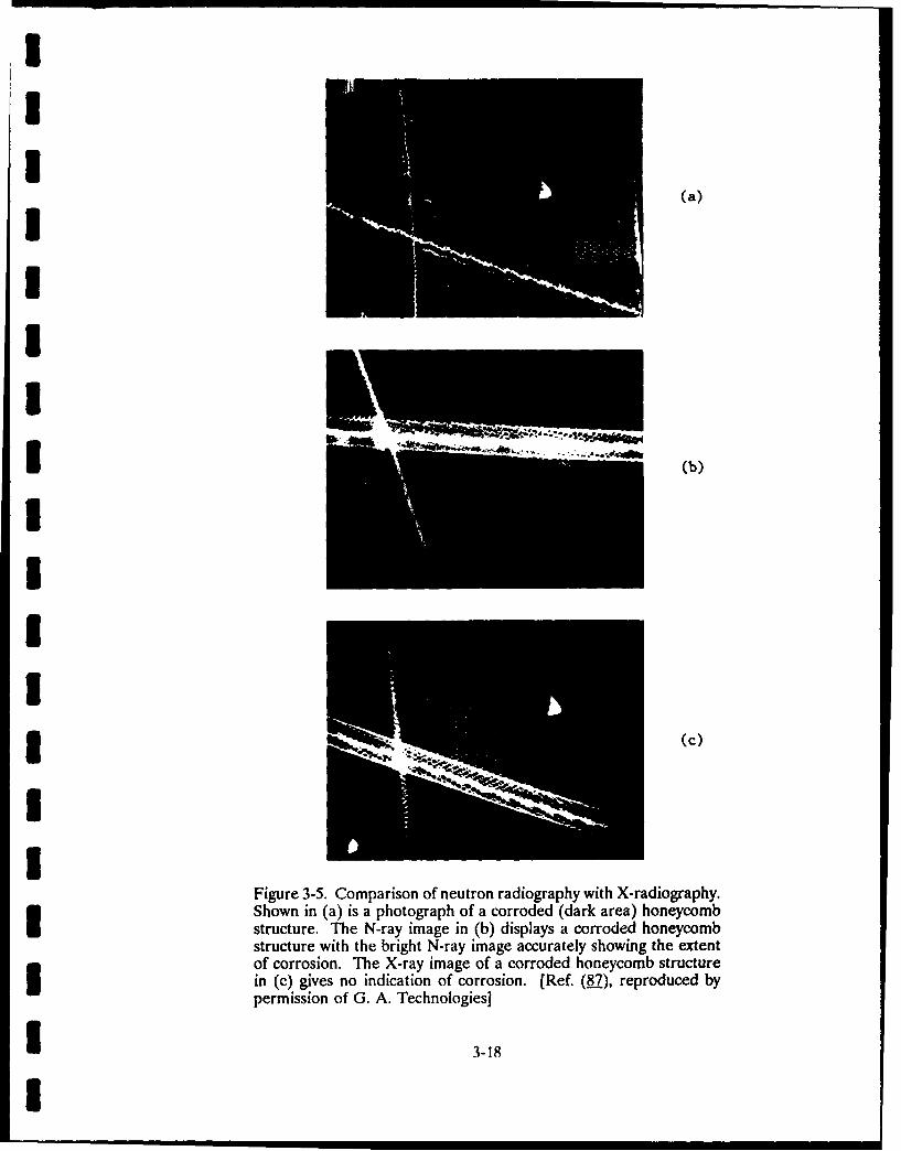
III
(a)III
III,
I
Figure 3-5. Comparison of neutron radiography with X-radiography.Shown in (a) is a photograph of a corroded (dark area) honeycombstructure. The N-ray image in (b) displays a corroded honeycombstructure with the bright N-ray image accurately showing the extentof corrosion. The X-ray image of a corroded honeycomb structurein (c) gives no indication of corrosion. [Ref. (7), reproduced bypermission of G. A. Technologies]
I 3-18
I
I
I for image enhancement. The mobile neutron detectable. Corrosion also could be detectedgenerator/imager designed by Dance et al was on the back side of an aluminum or mag-tested with several combinations of converter nesium skin with thickness up to 20 mils.screens and films, as well as a low-lighttelevision imaging system. Reference (23) Finally, Peters (8) employed yet anothercontains numerous examples of radiographs of technique to detect the presence of corrodentaircraft structures obtained in field testing of materials deposited on steam-generator tur-the equipment. The system was delivered to bine blades. His system used 14-Mev neutronsthe Army and is now installed at the Army from a neutron generator, time-of-flight gatingMaterials Technology Laboratory. instrumentation, and a NaI(Tt) scintillator
detector and associated gamma-rayCrosbie et al. (25) addressed a different spectroscopy equipment. The idea was that
aspect of neutron source development. In an 14-Mev neutrons interact with the nuclei ofeffort to reduce the cost of a high-intensity atomic constituents (principally Na, Cl, S, andCf-252-based radiographic facility, they 0) of the corrodent material to producedesigned a stationary system that used a sub- gamma rays through inelastic scatter. Thecritical assembly of enriched U-235 fuel plates energies of gamma rays produced in this wayin a moderating medium. When a relatively are characteristic of the targe: nuclei and cansmall amount of Cf-252 is introduced into the be used to detect their presence throughassembly, neutron multiplications is achieved measurement of the backscattered gamma-raythrough interactions with the U-235. The end spectrum. The time-of-flight system was usedresult is that a much higher neutron flux is to eliminate much of the background radia-available for radiography than would be the tion produced by neutron interactions withcase with the same amount of Cf-252 alone, other materials by selecting a time interval
corresponding to the distance from the sourceInstead of conventional through- to a turbine blade and back to the detector.
transmission radiography, backscattered radia- The system used by Peters had a source inten-tion, together with some form of tomographic sity of 10 neutrons/s. and was capable ofdata processing, can be used to produce detection 10-3 g/cm 2 Na with an exposure timeimages of corrosion damage in structures of 104 s.where access is limited to only one side.Preliminary results from a system using G. Thermographygamma-ray backscatter for the inspection ofoffshore structures were reported by Bridge Thermography is the study of theet al. (26). They used a collimated CoWo temperature pattern of a specimen's surfacesource with an array of 16 collimated detectors on application of heat. Thermography can beto build up images of data from volume ele- used to detect flaws because, after inducing aments corresponding to the intersection of thermal impulse, the flaw affects the transientsource and detector collimator solid angles. response of the surface temperature. ThisTheir work included a discussion of the proba- technique can also be used to detect loss ofbilities of void detection and false alarm as a thickness by corrosion under paint.function of imaging speed.
McKnight and Martin (28) foundAnother form of backscatter inspection infrared thermography to be a feasible method
was reported by Frasca et al. (27). They used to evaluate the performance of coatings onbackscattered beta radiation for the detection steel in the laboratory. The presence of local-of corrosion products under an epoxy coating ized corrosion products under an intact filmon an aluminum substrate. The system makes and air- and water-filled blisters was observeduse of a Sr 9° - Y90 collimated and shielded as varying gray levels representing tempera-source with plastic scintillator detectors ture variations. The localized corroded areamounted alongside. Experiments with artifi- appeared hotter than the surrounding area.cial flaws filled with corrosion products indi- Neither corrosion nor blistering was observedcated that pit depths of 2 to 20 mils were on visual inspection. They were able toII 3-19

I
3 resolve slightly corroded and blistered areas steam flash. In the first method, hot water1 mm in diameter on smooth substrate:,. For was introduced into the boiler tubing; and the50-pm profile sandblasted panels, the resolu- line at which the water came in contact withtion was about 1.2 to 1.5 mm. For the coated the dry tubes as it rises was observed. Duringpanels exposed to an elevated humidity and this procedure, the areas with thinning weretemperature environment, water-filled blisters expected to get hotter at a faster rate thanunder a pigmented film and localized corrosion the surrounding tubing areas. The tempera-under a clear film could be detected if the ture differential between the two areas can bediameter of the area were greater than 1 mm. observed, however, during a short period ofThey recommend further research to improve time with the infrared camera.the resolution sufficiently to detect the initialbreakdown of the coating/substrate interface In the water-spray method, theon smooth or sandblasted substrates. instrument was focused high on the tubes. A
water spray was directed into the tubes justPreliminary tests by Birring et below the point of focus, and then the spray
al. (11) showed that thermography was able to and the focus were moved together down thedetect 3-mm deep, 50-mm diameter, flat- tube surface. The instrument followed thebottom holes in 6-mm thick aluminum plate. spray so that the focus delayed the spray byA flame from a propane torch was used to 1 second while scanning the tube surface.instantaneously heat the surface opposite the When using this method, the flaws where wallside-drilled hole, and the temperature of the thinning had occurred showed a hot spot forheated surface was then measured by an AGA a short period of time (s 1 second).thermovision camera. The area at the oppo-site side of the side-drilled hole was found to The third method, steam-flash,be hotter than the remaining areas until a introduced superheated steam into the boilersteady state was achieved. Experimental tubes suddenly; and the temperature of theresults showed that thermography can detect tube surface was observed with the infraredlarge changes in thickness (v50 percent) of camera. The thin area showed a hot spot forplates. The method is difficult to apply in a short time (ou1 second) until the steady statedetecting small thickness changes due to was reached. This method has some draw-corrosion. backs for use in a boiler because sudden
changes in boiler temperature could produceBirring et al. (I1) also used high stresses, which may be detrimental.
thermography to successfully detect corrosionunder paint. For the experiments, a 1500W Of the three approaches described,lamp was used to heat the plate surface for a the water-spray method had the maximumshort time ( I1 second). The surface tempera- potential for field application. The methodture of the specimen was monitored by a was able to detect flaws deeper than 50 per-thermovision camera. Photographs clearly cent of tube thickness with a minimum diam-showed the hot areas where corrosi~in was eter of 7.5 mm. Water-spray examination canpresent. Besides the fact that the method suc- be done at a speed of 78 square meters percessfully located corrosion on several plates, minute.an additional advantage of thermography wasits speed, which reduces inspection costs. This H. Ultrasonicsmethod also is easy to apply for aircraftinspections. Ultrasonics has been used to detect
corrosion in a range of applications. In mostResearch into the application of of the cases, the conventional techniques have
thermography to detect corrosion in boiler been directly applied or applied with minimaltubes was funded by the Electric Power modification. These techniques are based onResearch Institute (EPRI) (100.., 101). This the analysis of high-frequency sound waveswork covered three approaches for heating the reflected/scattered from a discontinuity. Theboiler tubes: rising water, water spray, and discontinuity could be a crack, pit, or any other
II 3-20
I

I
anomaly that can be caused by corrosion. The can be used to a certain level of roughness;most common analysis of ultrasound includes then their performance degrades, and errorsdeterminingthe reflected signal and measuring in thickness measurement increase. Selectionits amplitude and arrival time. A signal of an ultrasonic technique with increasedindicates a flaw or discontinuity with signal surface roughness is summarized in Table 3-2.amplitude relating to flaw size and arrival timeestablishing flaw location. Advanced ultrasonic Detection of hidden surface cor-techniques include measurement of small rosion can also be performed by ultrasonics.changes in velocity (less than 1 percent), analy- In such a case, scattering caused by corrosionsis of the backscatter from the microstructure,and application of complex wave modes.Enhancement of ultrasonic results is provided is used as an indicator of corrosion (._). Withby imaging, signal processing, and pattern no corrosion, the ultrasonic reflected signalsrecognition. Some of the latest advances and are well resolved and free of noise.future areas include application of electro-magnetic acoustic transducers (EMATs) and 2. Pitting CorrosionI phased-array technology.
Inspection of components with pit-1. Surface Corrosion ting corrosion (pits greater than 2-mm diam-eter) is more difficult than generalized surface
Surface corrosion is measured by corrosion. An immersion transducer with athe ultrasonic pulse-echo method, i.e., an ultra- bubbler, as described earlier, could be used
sonic transducer transmits waves towards the when pitting is only present on the surfacespecimen; signals are reflected from the front opposite the transducer. The ultrasonic beamand back surfaces, and the time difference should be focused within the thickness of thebetween these two signals is used to measure specimen where the bottom of pits is expected.the remaining thickness (see Figure 3-6). Beam focus reduces scattering from the sur-I These measurements can be taken with com- face, as the beam is incident in a small area.mercially available digital thickness gauges if Another approach for such an application hasthe specimens have smooth surfaces. The been reported by Splitt (103). They have usedperformance of the digital gauges degrades a dual transducer where the ultrasonic beamrapidly with an increase in surface roughness incident on the bottom of the pit is reflected(102) (see Figure 3-7) because of ultrasonic to the transducer (see Figure 3-9). A scanningscattering (Figure 3-8). With extremely rough system called corroscan for pipes and riserssurfaces, performance degradation can cause has been developed by Det Noske Veritasrandom numbers to be generated by the digital (104). It consists of a meter water part oper-readout. Digital thickness measuring instru- ated by a diver, with registration and process-ments, therefore, are not recommended on ing equipment placed over water,rough surfaces. Instead, an analog representa-tion of the signal (see Figure 3-6) can be used Another system for detection ofto identify the front and back surface reflec- corrosion in naval boilers is discussed bytions for corrosion application. Peters et al. (105). A very satisfactory
semi-automatic conversion probe wasWhen only one of the two surfaces developed to evaluate external corrosion in
is corroded, the transducer is placed on the generator tubes above the mud drum of navalsmooth surface for good contact. When boilers. To accomplish this inspection of ainspecting from the corroded (rough) side, a steam generator, Furlan et al. (106) developedbubbler with a water column for coupling the an internal probe with a helical minimum.ultrasound can be employed. Bubblers have Designed to detect cracks, the system can alsoan added advantage of using focused trans- detect OD corrosion.ducers to direct the beam inside the specimenand reduce the scattering noise (102). The Conventional ultrasonic methodsfocused transducer and bubbler combination cannot be applied when pitting inhibits
I* 3-21

II
Ultrasonic1 Transducer Front AT
SurfaceV
Front E /BackSurfacei Surface /
Time
Back Surface
Figure 3-6. Thickness measurement method. The time difference between theultrasonic signals reflected from the front and back surfaces is used to calculatethickness.
I100
80 -- Krautkramerua Novascope 2000DIo- Sonic 220
III
UITMV 110540 - Balteau UTG5A
I20 -
0
IoI I 1I 1 I0.1 0.2 0.3 0.4 0.5 0.6 0.7
Surface Roughness RMS mm
Figure 3-7. Measurement error for commercially available thickness gauges.Thickness measurement error increases with an increase in surface roughness
I (102).
33-22

I
U UltrasonicTransducer
"oNoiseI
Time bo
(b)
3 Corroded(a) Plate
Figure 3-8. Thickness measurement of corroded plate using conventionalultrasonic method. (a) Scattering is caused by corroded surface. (b) Back-surface signal cannot be resolved in scattering-generated noise (102).U
ITable 3-2
APPLICATION OF ULTRASONIC TECHNIQUES TO MEASURE REMAININGTHICKNESS ON SAMPLES AFFECTED BY SURFACE CORROSIONUSurface Condition
Inspection Side(in contact withthe transducer) Opposite Side Ultrasonic Techniques
Smooth Smooth Digital Thickness GaugeSmooth Rough Contact/BubblerIISmooth Extremely Rough Bubbler with Focused
TransducerRough Smooth BubblerRough Rough Bubbler
Extremely Rough Smooth None of the Above
Note: Rough: pit depths less than 2 mmExtremely rough: pit depth greater than 2 mm
IIi3 -23

T R
V VQ T V 'U ,r Tme"
I T = Transmitter IE = Incident echo from the front surfaceR = Receiver PE = Pit echo
Figure 3-9. Sound reflection from a pitting hole. The time difference between IE andPE gives the remaining thickness [Ref. (L03), reproduced by permission of the ScientificResearch Institute of Introscopy].
resolution of the front- and back-surface disoriented cracks and the high noise levelssignal. In such cases, a technique developed from the stainless-steel grains that lower theby Birring can be used (107). In this tech- signal-to-noise (SNR) ratio.nique, an ultrasonic focused transducer isaligned over the pit (see Figure 3-10). The To address this need for reliablesurface of the pit acts as a lens collimating the detection, EPRI initiated several programs onbeam in the material. Well resolved front- and NDE technique development and conductedback-surface signals are obtained to measure round robin tests (108.), which have had athe remaining thickness. limited success !o far. Some of the conclu-
sions from the literature regarding detectionUltrasonics can also be used to of IGSCC in stainless steels are:
measure pit depths. In such a case, a trans-ducer that focuses the beam over the front (1) Desired frequency range forsurface is employed. The arrival time of the detection is 1.5 to 2.3 MHzfront-surface reflection is used to map the (108,109).profile of the cmoet
(2) The irregular shape of IGSCC3. Cracking produces a broader angular
scattering pattern than fatigueConventional crack-detection tech- cracks (LlQ).
niques are used to detect cracking in the formof IGSCC, SCC, or corrosion fatigue. These (3) Dual-element transducers pro-techniques generally use refracted shear or duce a higher SNR than doeslongituiinal waves transmitted at an angle of a single element (109).30 to 60 degrees. The reflected signal fromthe crack indicates its presence. Although (4) Spatial averaging improvesconventional ultrasonic techniques are widely SNR (109).used, their performance is unsatisfactory.Conventional methods are known to have low (5) Longitudinal waves work betterprobabilities of detection, especially for IGSCC than shear waves for flawin stainless steels. The problem with crack detection in welds (109).
* detection is the low amplitude signal from the
3-24

I Another method to detect cracks is frequency. Prikhod'ko (116.) has calculated theto use Lamb waves. Alers (I1), Salzburger velocity and attenuation changes in stainlessand Holler (112), and Datta et al. (113) have steels with a distributed intergranular attack.used electromagnetic acoustic transducers Prikhod'ko also provides experimental data to(EMAT) to detect cracks using Lamb waves, validate his theoretical results.The major advantage from EMAT is thatinspection can be done in a noncontact mode, One of the areas where ultrasonicsallowing high-speed and high-temperature has been successfully used is in the detectionapplications. Its low efficiency, how,"'er, of hydrogen attack. This is a phenomenonreduces the probability of detection. whereby hydrogen penetrates the metal, reacts
with carbides, and produces methane-filledExfoliation is another form of crack- bubbles in microcracks. The problem has been
ing produced by corrosion. Hagemaier (26) known to exist in petrochemical and fossilhas reported a simple ultrasonic pulse-echo plants. Hydrogen attack can be detected fromtechnique to detect corrosion around the a reduction in the ultrasonic wave veloci-fasteners in aircraft structures (see ties (120,21,122). In fact, the reduction in theFigure 3-11). An ultrasonic transducer is longitudinal-wave velocity (vt) is more thanplaced at the periphery of the fastener holes, that for shear waves (v5). This results in aand the backwali signal is monitored. Exfolia- reduction of the ratio vt/,, or t/tt, where ttion in the holes obstructs the sound waves is the transit time. The act that the ratio canand results in a loss of backsurface signal. be a useful parameter allows an inspection toThis technique can be further improved by be performed without knowing the thicknessusing focused transducer beams directed more of the component (121).5 toward the exfoliation damage.
The backscatter technique also has4. Material Degradation a major potential for nondestructive materials
characterization of materials. Goebbels (115)Ultrasonics is one of the most pioneered the application of this technique for
powerful methods for detecting material degra- taking grain-size measurements. The tech-dation. Material microstructure can change nique has been successfully applied to detectultrasonic velocity, attenuation, or backscatter. microcracks, inclusions, and segregates.Cavities and microcracks in the material Birring (120) applied the technique to detectreduces the ultrasonic velocity and increases hydrogen attack and measured a 21-dBattenuation (1.,112, 114-117). Impedance increase caused by hydrogen attack in a 1.8-cmmismatch at the grain boundaries in the mate- thick pipe sample (see Figure 3-12).rial increases ultrasonic backscatter. Furtherinformation on the microstructure can be While the backscatter techniqueobtained by analyzing the ultrasonic param- shows a major potential, there are some draw-eters with variations in the frequency. backs. When inspecting materials, backscatter
will be produced by microcracks and inclu-Theoretical work in this area has sions; and it may be difficult to differentiate
been done to show the quantitative effects of between the two. Nakashiro (123) has con-microstructure on ultrasonic velocity and ducted spectral analysis of the backscatteredattenuation. Temple (118) showed a reduc- signals to resolve such issues.tion in wave velocities with microcracks. Hepredicted the reduction to be more for Ion- Ultrasonic materials characteriza-gitudinal waves than for shear waves. tion is a fairly new development in nondestruc-Goebbels (115) and Birring (119) have also tive testing. This area is expected to becomereported the velocity to be dependent on the much more significant in solving problems
I
i3 -25

I
U FocusedTransducer
3 Focal Point
Front SurfaceI
IiBack Surface
Um Figure 3-10. Focused transducer concept. The curvature of the pit collimates thediverging beam in the steel plate, resulting in a strong back-surface reflection (107).
Al 1 -2
I - -4II I ! I Response From Unpainted Or
S-Normal Paint Thickness -No Corrosion
I 2
2i
Response From Corroded Area-""- Loss Of Back Reflection
Figure 3-11. Contact ultrasonic CRT responses at 10 MHZ3 [Ref. (26), reproduced by permission of Materials Evaluation]
3 3-26
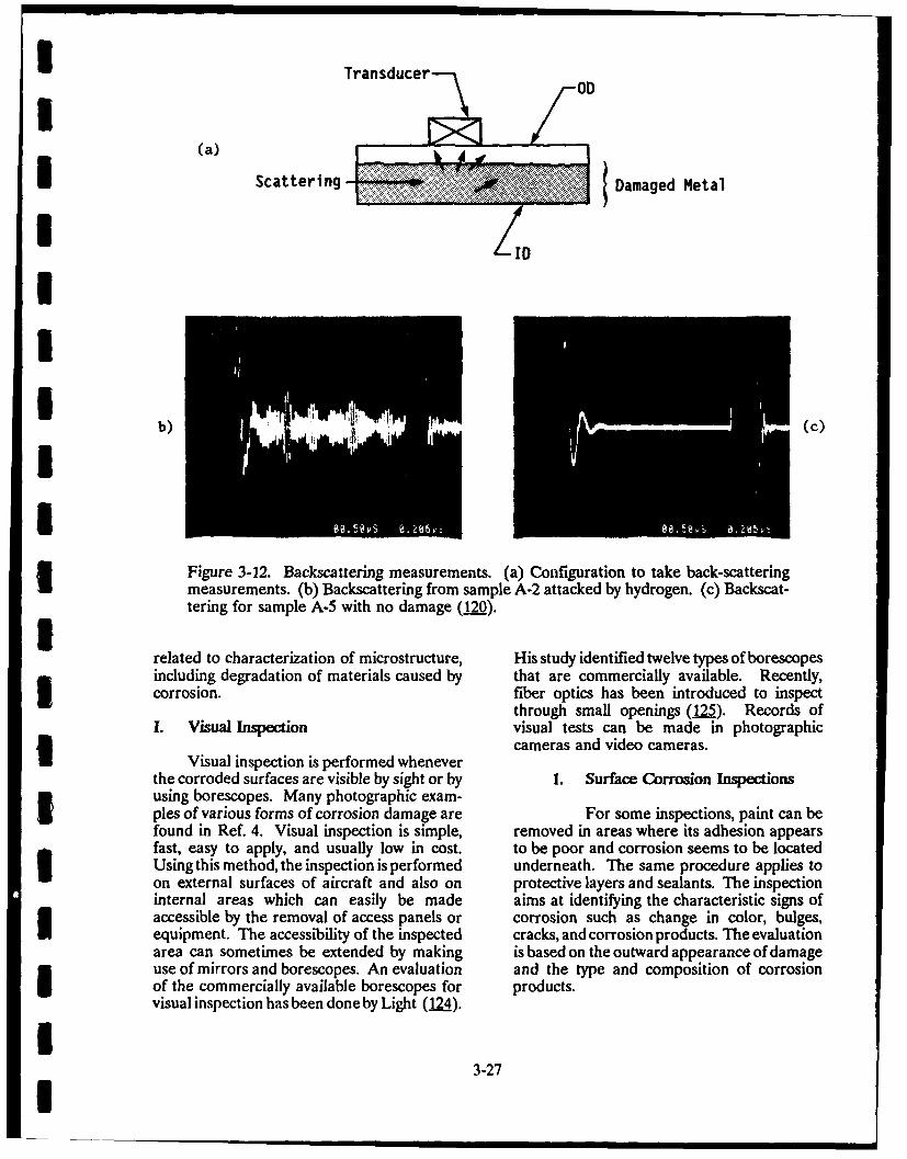
I Transducer
Scattering Damaged Metal
I,
I'Z(c
Figure 3-12. Backscattering measurements. (a) Configuration to take back-scatteringmeasurements. (b) Backscattering from sample A-2 attacked by hydrogen. (c) Backscat-tering for sample A-5 with no damage (120).
related to characterization of microstructure, His study identified twelve types of borescopesincluding degradation of materials caused by that are commercially available. Recently,corrosion. fiber optics has been introduced to inspect
through small openings (125). Records ofI. Visual Inspection visual tests can be made in photographic~cameras and video cameras.
Visual inspection is performed whenever
the corroded surfaces are visible by sight or by 1. Surface Corrosion Inspectionsusing borescopes. Many photographic exam-ples of various forms of corrosion damage are For some inspections, paint can befound in Ref. 4. Visual inspection is simple, removed in areas where its adhesion appearsfast, easy to apply, and usually low in cost. to be poor and corrosion seems to be locatedUsing this method, the inspection is performed underneath. The same procedure applies toon external surfaces of aircraft and also on protective layers and sealants. The inspectioninternal areas which can easily be made aims at identifying the characteristic signs ofaccessible by the removal of access panels or corrosion such as change in color, bulges,equipment. The accessibility of the inspected cracks, and corrosion products. The evaluationarea can sometimes be extended by making is based on the outward appearance of damageuse of mirrors and borescopes. An evaluation and the type and composition of corrosionof the commercially available borescopes for products.visual inspection has been done by Light (124).
33-27I

I
I 2 Cracks Inservice inspection of these pitsrequires removal of the lubrication fitting and
Large cracks can be detected by grease from each hole. The internal surfacecareful visual inspection. Hagemaier (126) of each hole is checked using a 0-degreehas given examples of detecting SCC in alu- (forward-looking), 2.8-mm diameter endo-minum landing-gear forgings, aluminum frame scope, which is a high-quality medicalforgings, and steel main landing gear. borescope. If corrosion products or pitting are
revealed, the hole is checked a second time3. Pits with a 70- or 90-degree (side-view) endoscope.
When pits are detected, the beam is removedVisual inspection has been used to from the aircraft; and the pits are removed by
detect pitting corrosion in high-strength steel, oversizing the affected holes.main-landing-gear truck beams. Corrosion canoccur in the four lubrication holes if the Borescopes are extensively used tolubrication (grease) is not replaced at periodic detect pitting corrosion in boiler tubes. Someintervals as specified by the aircraft main- experience is required with borescopes to gettenance manual. The pitting, if undetected, the depth information of pits because bore-can result in stress corrosion. scopes have a single viewing window, which
inhibits a 3-D projection.
I3IIIIIIUI
I|
I

I IV. CORROSION DETECTION NEEDS
i Corrosion occurs in a variety of components not identified. Certain assumptions regardingand structures. The National Bureau of Stan- the proportion of corrosion-related work at thedards (NBS) report published in 1978 (2) fleet, tender, and shipyard repair levels wereprovides an exhaustive list of industrial cor- made. In summary, the Coast Guard annualponents affected by corrosion. The report corrosion cost at $7.5 million and the Navyalso computes the total losses due to corrosion cost at $392 million produced a total cost offor each of the industrial sectors and estimates about $400 million for ships, which is 0.7 per-the corrosion costs that could be avoided, cent of the estimated Federal capital in shipsWhile it is not possible to cover each of the of $56 billion.areas in detail, this section discusses in alimited way the corrosion needs relevant to the Real property (buildings, structures) comprisesFederal Government and specifically to the 36 percent of the total Federal capital. TheDepartment of Defense (DoD). inventory is quite variable, with ten types of
buildings and sixteen types of structures.The authors of the NBS report obtained data Because it was not possible to examine thefrom the three services of DoD, National corrosion costs in all cases, data from DoD,Aeronautics and Space Administration which owns about 70 percent of the Federal(NASA), Coast Guard, Government Services buildings and structures, were used to deduceAdministration (GSA) Legislative Branch, and total losses. The annual DoD corrosion main-NBS. Maintenance and repair costs for these tenance costs were calculated to be $280agencies came from various sources. In a few million. Data were also gathered from thecases, corrosion costs were found; generally, Coast Guard, NASA, GSA, and NBS; andhowever, careful estimates of the fraction of total Federal real property corrosion main-losses due to corrosion were required. The tenance costs were determined to be $375total capital items considered here were esti- million annually.mated to represent $650 billion (97.6 percentof those owned by the Federal Government). Combining the expenses for aircraft, ships,They included real capital (buildings and struc- and real property leads to an annual main-tures, for example) and "personal" capital (air- tenance corrosion cost estimate of $1.775craft, ships, and ordnance, for example). Cor- billion on 84 percent of all Federally ownedrosion cost information was determined in this capital. Based on that, a total cost of corro-study for 83.4 percent of the total capital sion maintenance in the Federal sector is esti-owned by the Government. Costs for the mated to be about $2 billion annually.D remainder were then estimated.
d wTo determine the full effect of corrosion inInformation on aircraft was obtained from the the Federal sector, costs caused by the needAir Force, Navy, and Coast Guard. The total for redundant capital and by shortening ofFederal capital in aircraft was estimated to be equipment lifetimes due to corrosion must$195 billion. The annual corrosion main- also be included. For example, in the case oftenance cost of these was estimated to be $990 Federally owned aircraft, there is no estimatedmillion. Lifetime in service was judged to be change in lifetime, but there is an estimatedunaffected by corrosion, but was instead deter- 6-percent capital redundancy. This causes amined by obsolescence. However, a redundant yearly capital redundancy cost due to corrosionexcess of aircraft of 5 to 8 percent results from of $2.4 billion, compared to a yearly main-the influence of corrosion on aircraft tenance cost of $986 million. In other casesdowntime. such as automobiles, there is little redundant
equipment; but the lifetime is shortened.Detailed maintenance records were available When the considerations are applied to all thefor ships in both the Navy and Coast Guard capital equipment of the maintenancefleets; however, corrosion-specificactionswere expenses, these corrosion costs together
g 4-1

amount to about 2 percent of the Federal Realizing corrosion as a major discipline ofbudget. Of the $8 billion total cost of interest, the three services started a literaturecorrosion to the Federal Government, about database entitled Corrosion Information and20 percent is estimated to be avoidable. Analysis Center (CORIAC). The CORIAC
files can be accessed through the Metals andIn the next few subsections, some of the corro- Ceramics Information Center (MCIC) data-sion NDE needs for specific branches of DoD base. Currently, the CORIAC files center hasare identified. While an effort was made to approximately 1000 records of information.identify individual needs, some do overlap.For example, all three branches use helicopters The following three subsections discusses thethat have the same corrosion problems. problems related to Army, Air Force, andCorrosion of reinforcement in buildings is Navy, respectively. Because of the overlap inanother common problem, and so is the the problems among the three services, it isweather. The geographical area has a strong recommended that all three subsections beinfluence on the corrosive nature of the envi- read.ronment. Figure 4-1 shows the corrosion envi-ronments in the United States (27). In A. Army Corrosion Problemsgeneral, cc rrosion is more severe in the North-east, Southeast, and along the West Coast of Corrosion problems for the Army occurthe United States. The severity of corrosion in helicopters, aircraft, land vehicles, facilities,is less in the Central United States. and monitors. The problems related to the
aircraft are common to the Air Force andCorrosion problems related to DoD occur in Navy and are covered in the subsection onI a wide range of components, including aircraft, Air Force problems.ships, land vehicles, buildings, and munitions.Importance to corrosion problems usually is Baker (1N) from the Army Aviationgiven when it directly affects the safety, fleet R&D Command has given several examplesreadiness, and depreciation of value. Because of corrosion in helicopters. He addressedof these factors, aircraft have always been areas where a good NDE method could begiven prime importance with reference to used for field or department inspections. Thecorrosion. This was demonstrated when the major aircraft components affected were main-USAF organized a workshop in "Nondestruc- rotor mast extension, blade, and retention nut;tive Evaluation of Aircraft Corrosion" in pitch-change link; functional and nonfunctional1983 (28 28-32). Presentations during the main landing gears; and aircraft control tubes.conference were made by personnel from the He identified the need for an NDE methodAir Force, Army, and Navy to recommend for thickness measurement of corrosion-research and development programs dealing protection coatings whose thickness can reducewith the detection of corrosion in aircraft. with service. Another area in need of an NDE
method is the control tubes. Water enters theIn 1985, a NATO member conference on the control tubes, causing internal corrosion. The"Management of Corrosion" (72,127,13.) was extent of such corrosion can not be deter-organized by the Advisory Group for Aero- mined, and an NDE method is needed here.space Research and Development (AGARD). Unnecessary replacement of tubing is commonThis conference explored the relationship on older aircraft where the amount of corro-between environmental corrosivity and cor- sion is unknown.rosion problems in military systems. Fourmanagement strategies were discussed during Shaffer and Lynch (133) have identifiedthe conference: protective coating selection, corrosion problems experienced in recent yearsdesign of vehicles, determination of manufac- that resulted in avionic failures. The avionicturing and maintenance specifications for equipment that suffers the most fromaircraft, and special problems of marine environmental effects are those mountedenvironments, external to the airframe such as electronic
4I 4-2

I
IEXTI EMELY
[]SEERE
M MODERATE
C NEGLIGIBLE
Figure 4-1. "Marine" corrosion environments in the United States[Ref. (127), reproduced by permission of AGARD]
I countermeasure pods, photographic pods, Corrosion of land vehicles is anotherantennas, and lights. Because of their problem that the Army encounters. Theexposure to moisture from rainstorms or low- extent of land-vehicle corrosion depends a lotlevel flights over water, they are targets for on the geographical location (see Figure 4-1).corrosion. Two prime examples of susceptibil- Corrosion is more severe in humid areas nearity to this condition are the clamshell doors on the seashores and in the snow-belt regions.helicopters and radomes on fixed-wing aircraft. This problem is addressed by using anticor-These doors and radomes leak extensively rosion coatings. The military (127) recognizedwhen the gaskets become worn or damaged. the need for additional rustproofing to prolong
the useful life of its vehicles. The average ageAfter moisture or fluids enter an airframe of the commercial utility cargo vehicle is now
or avionic compartment, it may follow a 12 years. Other than the visual inspection,natural conduit directly into a sophisticated there is no other NDT inspection performed.piece of avionic equipment. Hydraulic and This is because the cost of an NDT inspectionfuel lines, control surface linkages, oxygen cannot be justified for a $15,000 vehiclelines, waveguides, structural stringers, and compared to $10 million missiles or a $200electrical wire/cable runs act as natural con- million aircraft.duits to moisture and fluids.
Downs and Gorak of the U.S. ArmyThe avionic systems on aircraft are not Tropic Center (134) conducted corrosion per-
isolated "black boxes" sealed against the formance tests of several military items in theenvironment. There are many compartments, Panama Canal Zone. These included tacticalswitches, lights, relays, terminal boards, circuit- radios, batteries, V-belts, automobile rollerbreaker panels, and so forth that make up a bearings, POL products, windshield wipercomplete system. In addition, a sophisticated motors, windshield wiper blades, intervalaircraft may contain miles of wire and coaxial timers, barrier material (plastic bags), andcables and hundreds of electrical connectors, practice rockets (90 mm). One of the objec-Corrosion attack on the various elements tives of their study was to learn how and whenmaking up the total avionic system can create to apply nondestructive test instrumentationnumerous problems in relation to reliability and techniques to test items. They were, how-and maintainability. Table 4-1 summarizes the ever, unable to accomplish this objective andeffects of corrosion on avionic components. recommended a state-of-the-art investigation
II 4-3

I
Table 4-1
I EFFECTS OF CORROSION ON AVIONIC COMPONENTS
[Ref. (133), reproduced by permission of AGARD]
* Component Failure Mode
Antenna Systems Shorts or changes in circuit constants and3 structural deterioration
Chassis, Housing, Covers, and Contamination, pitting, loss of finish, and3 Mounting Frames structural deterioration
Shock Mounts and Supports Deterioration and loss of shock effectiveness
3 Control-Box Mechanical and Intermittent operation and faulty frequencyElectrical-Tuning Linkage and selectionMotor Contacts
Water Traps Structural deterioration
Relay and Switching Systems Mechanical failure, intermittent operation,signal loss, and shorts
Plugs, Connectors, Jacks, and Shorts, increased resistance, intermittentReceptacles operation, and reduced system reliability
Multipin Cable Connectors Shorts, increased resistance, intermittent3 operation, and water seal deterioration
Power Cables Disintegration of insulation and wire/3 connector deterioration
Display Lamps and Wing Lights Intermittent operation and mechanical andelectrical failures
Waveguides Loss of integrity against moisture, reductionof efficiency, and structural deterioration
I Radar Plumbing Joints Failure of gaskets, power loss, and pitting
Printed and Microminiature Shorts, increased resistance, and componentCircuits system failures
Batteries High resistance at terminals, failure of3 electrical contact points, and structuraldeterioration of mounting
3 Bus Bars Structural and electrical failures
Coaxial Lines Impedance fluctuations, loss of signal, andstructural deterioration of connectors
3 4-4

I of NDT techniques for application to tropic surface area (highest priority), severity ofapplication to tropic development and attack in depth, site corroding activity, rate of3 surveillance testing. attack, and type of corrosion (lowest priority).
Corrosion of munitions can occur during Doruk (71) studied the kinds and causestheir storage. During storage, corrosion can of corrosion observed primarily in Type F-5Aresult in leakage of chemicals. Such leaks aircraft (see Figures 4-3 and 4-4). He reportswere detected in an expendable rocket- cases of pitting corrosion in wing and fuselagepowered target missile drone AQM-37A (135). skins and the drain-cavity section of jet-engineLeak studies performed over a 5-year period compressor casings (INCONEL W), andon such missiles showing extensive corrosion crevice corrosion in areas adjacent to non-of shear fittings could potentially create an metallic components such as fiberglassextremely serious leak problem. The U.S. antennas. Exfoliation corrosion was presentArmy Aberdeen Proving Grounds have pre- in the vertical stabilizer attach angle (com-pared a document that describes a range of bined with stress corrosion) (7075-T6), verti-nondestructive test methods for a range of cal stabilizer along the edge of the radomeapplications for materials testing (136). These (combined with stress corrosion), and insidemethods are applicable to cannon tubes, cast the air inlet ducts.armor plate, welded joints, projectile fuses, andvehicle track shoes. Stress corrosion cracking was detected
in the wing-to-body joint fitting (7075-T6),B. Air Force Corrosion Problems main landing-gear uplock support rib
(7075-T6), eye bolt of the landing-gear strut,A workshop on NDE of aircraft corrosion and H-link connected to the landing gear strut
organized by the USAF in 1983 recognized the (Figure 4-5). Bimetallic corrosion was foundcorrosion problems that needed immediate in holes in the vertical stabilizer attach angle,attention. The workshop piesented an over- holes under the wings through which the jawview of the many types of corrosion problems bolts were placed, holes in the magnesiumencountered in practice. Teal (28) discussed alloy covering plates under the fuselage, wingNDE needed for corrosion detection. These skins adjacent to countersunk fastener heads,included detection and determination of the and access panels and covers of magnesium inextent of corrosion without disassembly; detec- contact with aluminum. Honeycomb assemblytion of corrosion in multiple layers, under damage at the leading-edge sections of wingssealant, and beneath paint; identification of was detected.suspected corrosion by scanning large areas;and severity of corrosion inspection in complex Hardy and Holloway (1M2) have identi-geometries (see Figure 4-2). He also pre- fled key technology needs for airframe cor-sented successfully applied NDE methods for rosion. The items in the priority of rankingdetecting corrosion, including detection of are:single-layer corrosion by ultrasonics, tubularcorrosion by radiography, disbonds in honey- I. Faying Surface/Stackups: Rapidcombs by ultrasonics, and moisture in honey- coverage of large areas, improvedcombs by acoustic emission. discrimination between defects and
geometry changes, location of theCooke and Meyer (131) identified corro- layer containing the defect, and
sion problems in the Air Force and performed image damage (C-scan) (character-an assessment of the NDT methods (see ization of the extent) with provisionTable 4-2). His assessment criterion for NDT for permanent records.methods is rated by their ability to determine,in the following decreasing order of 2a. A/C Wheels: Crack detection withimportance, the extent of corrosion in the paint on. (The polyurethane coating
II 4-5
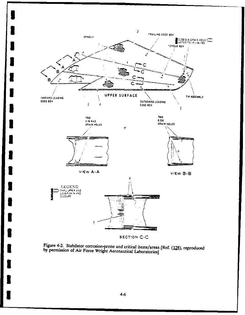
3 2 TRfAILING EDGE IOX
SPINDL 050 CIA GRAIN .4CLE1 .1FTE.R To iF-;§..7g3
//QUBG
BOX
7NOROL AON UPPER SURFACE TIP:OAA LEAINC TI
3~~ EDGE A- v~w8-42
VIu P E A -A VIEW
U SECTION K-Figure 4-2. Stabilator corrosion-prone and critical items/areas [Ref. (kreproducedI by permission of Air Force Wright Aeronautical Laboratories]
3 4-6

I
I>-A
i C, .
IIx
C CL
- 1 a, =
i i
CA"
.C t .. o. .)J,( -r .0 (5 a o c_
o•n - .
0 9 C.
.. (3 0. .. ( 3 ( (3 - (3 (3 (3 -.
I - Z . "za
Iz
to C..7
L CL C6 C
i 4--
• uw 0o -i C
6. C. C .C C . C
L* 4. I- Z:I . I .en 0. - .*U ~ . 0 L *.
51 CC CL
Ma 0 C C 06 0' C v 1
0 a*0. L. 0. 041 U : , z : E T :z it
.0 C 0~ 0 40 "1 1 v -a E= z ..- 4U
a. C. - a.. m
~ __ ___ ___ ___ __ _ ___ ____ ______
00GD 41.0C C'3C
0.. 0'- 0l
C .~ a. ~ . 0-7

I
II
1 1 11 *BIMETALLIC CORROSION3 EXOLIATiON AND sCC
_____OTHERS
UFigure 4-3. Locations of concentration of corrosion on the under section of the aircraftbody (F-5A). [Exfoliation and stress-corrosion cracking indicated on the figure are thosefound on parts incorporating the landing gears (71)].
I
I Figure 4-4. Locations of concentration of corrosion on the center and aft section of the
I aircraft body (F-5A)(71)
I4-8
I

Figure 4-5. Stress-corrosion crack in the H-link connected to the landing-gear strut,which was made visible using a fluorescent3penetrant (71).
3 is being removed solely to facilitate by "brute force" past minimumpenetrant inspections. Eddy current acceptable thickness). (Should anis specific to bead seat. A similar electrochemical approach be usedsituation exists for baked resin coat- or early detection of corrosion?)ings for low-temperature enginecomponents and for coated landing 5. Measurement of Coating Adequacy:gears. Rapid, full coverage is Remaining coating life (in originalneeded.) (The inspection technique condition and after a repair), ade-must easily adapt to the different quacy of application, and applicablesize rims that must be inspected.) to paints/primers/platings/conver-
sion coatings/ion-vapor-deposited2b. Honeycomb Panels: Rapid cover- (IVD) coatings/anodic coatings/etc.
age of large areas (e.g., large trans- (Are the protective barriersports), image damage (C-scan), more broken?) (For example, the capabil-realistic accept/reject criteria ity of current eddy current tech-recorded, detection of face/core niques is 0.005 mm to measurecorrosion, fluid entrapment (close- cadmium plating thickness on high-out damage leads to water intru- strength steel components due tosion), and adaptable to complex magnetic permeability and electricalgeometry. (Infrared was suggested. conductivity variations in plating andCurrently, visual and "con tap" substrate. The question is: Howmethods are being used.) can these variations be compensated
for when the critical plating thick-3. Corrosion Around Fasteners: Pro- ness required may be 0.008 mm?
vide rapid coverage of large areas Signal averaging by a microproces-(which areas require a second sor may be one possible method tolook?), provide indication of poten- reduce such errors. Specificationstial corrosion, establish detectability for preservation systems and coat-requirements, and provide inspec- ings are not applied as rigidly fortion data for interpretation by struc- replacement parts as they are fortural engineers. initial procurement. Uniform buy
standards are needed,)4. Quantification of Corrosion: Depth/
area of corrosion (i.e., determine the 6. Munitions/War Readiness Material:extent of intergranular corrosion Storage in "sealed" containers andbefore grinding a component down potential application for corrosion
I4-9I
I probe. (How can stored munitions Corrosion maintenance expenditures inbe inspected without removal from FY82 and FY83 for different types of aircraftcontainers or, minimally, without are listed in Table 4-3 (133). This list includesdisassembly?) most of the aircraft in the Navy's inventory.
A labor rate of $19 per hour, obtained through7. Corrosion Under Paint: Not a prob- the VAMOSC (Visibility and Management of
lem. (Fiiform and corrosion under Operating and Support Costs) AIR program,a sound coating system are not was used for these calculations. Whileproblems.) admittedly understated, the sum for just these
. Gaircraft amounts to over $120 million.I 8. Grinding Damage Under Platings
(e.g., Chrome Plating): More dis- In an effort to control the corrosioncrimination for base-metal damage. problem, the Navy washes all squadron air-(For example, sometimes techniques craft every 14 days. The Navy also inspectsare too sensitive to grinding patterns their aircraft for intergranular, galvanic, fili-without there being any damage in form, pitting, and surface corrosion. Some ofthe base metal.) the examples of corrosion and the applied
inspection methods are as follows (129) (see9. Need for Standards, Qualified Figures 4-6 to 4-8).
Inspectors Knowledgeable in Cor-rosion and Structural Mechanics, Holland, from Naval Air Systemsand Sufficient Equipment Appro- Command (129), has cited some of the currentpriate for the Depot or ALC Level NDT test procedures (see Table 4-4). In mostI and for the Field Level. cases, components must be removed for air-
craft to be examined. Corrosion must alsoTo develop a suitable NDT technique for be at a fairly advanced stage before it is
corrosion detection, the USAF funded a proj- detectable. The currently used equipment isect (84) in 1984. The objective of this project manually operated, is subject to operator inter-was to develop nondestructive evaluation tech- pretation, and lacks permanent records.niques for locating and characterizing corro- Certain cases also require paint stripping.sion hidden in aluminum alloy airframe struc- Because current inspection methods are verytures. The candidate NDT techniques were slow; the inspections are usually limited torealtime x-ray, realtime neutron radiography, small areas. NDT methods and systems are,and low-frequency eddy current (84). The Air therefore, required to overcome the aboveForce is now in the process of funding another limitations. The Navy is also interested inNDT project in new corrosion NDT techniques pursuing work in methods to detect interfacein fiscal year 1988. Hardy and Holloway corrosion, corrosion under paint, automatic(132) have reported key needs in technology corrosion mapping, real-time radiography,for corrosion detection. neutron radiography, and phase-sensitive eddy
current for far-side corrosion.C. Navy Corrosion Problems A comprehensive investigation of cor-
Navy's corrosion problems are intensified rosion-related failures in the Canadian Mari-by their close association with seawater. time has been prepared by Hollingshead andNavy's seagoing vessels such as ships and sub- Hanlan (1L7). Their investigations are dividedmarines are directly affected by seawater into three categories: machinery, seawatercorrosion. The waterfront facilities also systems, and general. The machinery categorydeteriorate by corrosion. The Navy's aircraft includes examples of corrosion problems withare exposed to the salt and moisture and, desuperheater tubes, gas-turbine engine-fueltherefore, corrode more than their counter- manifolds, and waste heat and auxiliary boilers.parts in the Air Force. The seawater category describes the erosion/
4* 4-10

I
U Table 4-3
COST OF NAVAL AIRCRAFT CORROSION*I[Ref. (133), reproduced by permission of AGARD]
U Aircraft FY82 FY83
A-6 18.1 17.8A-7 16.8 18.6C-130 2.0 2.6E-2 4.3 4.8F/A-18 0.1 0.5F-4 9.6 7.4F-14 12.0 14.2H-2 4.1 4.4H-3 8.4 9.1H-46 7.0 7.5H-53 3.4 4.5P-3 14.9 19.4S-3 7.9 8.7AV-aA 0...50__5
TOTALS 109.1 120.0(10 percent increase)3 Labor Rate = $19/DMMH
*Includes only organizational and intermediate levels of maintenance
I -
3W, L. 7 1
8 1 LH Forwarc Piion3. Tunnel
3 4. Cameo OecK
5 LH StuowingSTA 410 7 I Nose
J6 8$ Lh A.- Pylonl*. 1a I LM .uselaoe
I 7 STA 120
Figure 4-6. Identification of inspection zones - H-46 [Ref. (129), reproduced by3 permission of Air Force Wright Aeronautical Laboratories]
4i 4-11
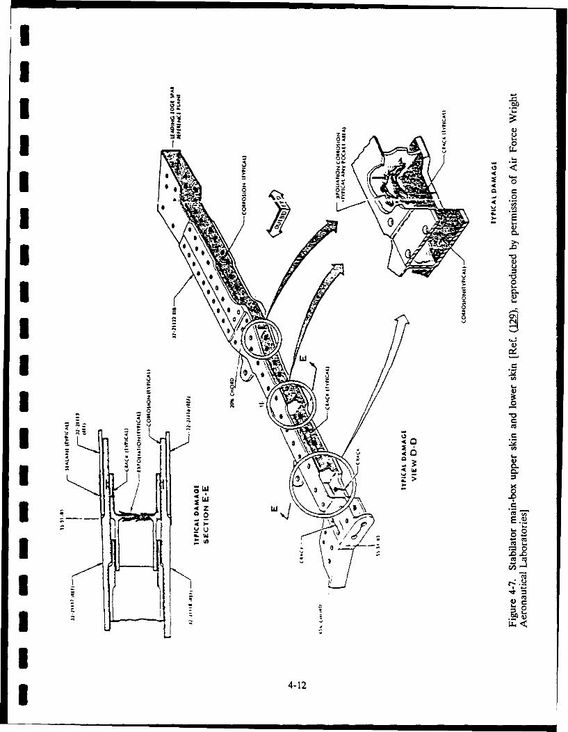
UU
44-.
CoI -~ 4
4 a)- U
04 - I-.
0-* -- 0-aI
z -4I 6. 2 a- 0
- .( .~U 6 5* - 4)
S
0 .06*.~U *O.?
6 0..I * 0 a)
* S*SSOO CS a)
-~I *\ C
in
0 1~.a)I
- 0- -o
-- -. Cu4 .- -
~ Z4- 0
- 44 -- I-.
0..
I ~o Cu ~'- - ~
I-I '-0
0.-:u) Cu
- cuL.UCu
* - r-
I Cu'C
I - '-0I - -
U3 4-12

271132 '4ONIYCOMI8 ASUMIlL
IV THE X.D AAOWDER
DINOTE '?IA O CINSTERI
GLWE SURTFACEAAN
3211 0 RA ON jYO0 S(AL
322 A.BEIO $ONN
32;I 7 S4: UEf
7- Is N LOW:.
322.2 13 SKIN
INBOARD '94 C5 118
E''LZ3T2 tZI C.S
32211 __F.--
Figure~S 4-8. StbLtrmi-o pe kn owrsiadrb[e(2) EpruENDby ~ ~ ~ ~ ~ f permissio ofE Air Forc Wright AeoauiaELbrtois
4EO?$-ORO3O

* Table 4-4
CORROSION EXAMPLES AND NDE METHODS APPLIED)[Ref. (I29), reproduced by permission of Air Force Wright Aeronautical Laboratories]
Corrosion-ProofComponent NDT Method Type of Corrosion Areas
1. H-46 Rotor X-Ray Galvanic Spar Back Wall, InteriorBlade of Spar, STA 286
2. H-46 Ultrasonics Galvanic Mounting FlangeEngineExhaustDevice
3. H-46 Stub Eddy Current Multiple Stub-Wing FittingsWing Mechanisms
4. H-46 - Ultrasonics Exfoliation Drive ShaftH-53DeviceShaft
5. Landing Ultrasonics Exfoliation/ Inside of TelescopicGear on Pitting MechanismNavyAircraft
6. F-4 Stabi- X-Ray Intergranular Center Riblizer Rib
7. H-4 Stabi- X-Ray and Exfoliation Skin3 lizer Skin Ultrasonics
8. H-1 and Ultrasonics and Pitting Doubles and SpanH-2 Main Harmonic BandRotor TestsBladeI
corrosion of copper/nickel pipes and pump more chances there are for preventingimpellers and crevice corrosion of pump shaft. corrosion. A summary of the corrosionThe general category includes corrosion prob- problems in the Canadian naval fleet followslems with hulls and fasteners. (1L7).
Hollingshead and Hanlan (137) have Avionic corrosion is also a major prob-emphasized the role of corrosion training in lem for the Navy (M3). This aspect wascombating corrosion. The more personnel covered in Army Problems, Section IVA (seeare aware of elementary fundamentals, the Table 4-1).
II 4-14

I Component Type of Corrosion
1. Solar Saturn Fuel Manifold in Destro- Chloride SCCyers
2. Desuperheater Tubes in Ships SensitizationCarbide Precipitation
3. Waste Heat and Auxiliary Boilers Chloride SCCOxygen Pitting
4. Dealuminification of Aluminum-Si- DealuminificationBronze Valves and Pittings in Destro-yers
5. Firemain Brazolets (Si-Mg-Bronze) Erosion/Corrosion
6. Seawater Pump-Shaft Stainless Steels Crevice Corrosion
7. Pump Impellers Erosion/CorrosionCavitation
8. Firemain Pipe Corrosion Erosion/Corrosion
9. Weld Corrosion in Bilges Electrochemical Potential
10. Fitting from Helo Hauldown Stress-Corrosion Cracking (SCC)
11. Pelican Hooks SCC of High-Strength Alloy
I 12. Aluminum Landing Craft Hulls Exfoliation Corrosion
3 Brackett (138) has reported the exten- occurs when the corrosion products causesive corrosion in the naval waterfront the volume of the structural element tofacilities that were mostly built in the early expand, resulting in tensile stresses and1950s. Most of these facilities have cracking. As corrosion progresses, thereached or exceeded their original design corrosion products expand, causing morelife, resulting in escalating maintenance cracking; eventually spalling occurs,and repair costs. A study on the factors exposing the steel reinforcement. Rustinfluencing ultrasonic inspection offshore stains on the surface of the concrete arestructures was performc" by Birring for usually the first visual indications ofthe U.S. Coast Guard (fL9). This study corrosion of the reinforcement; however,outlines the various factors such as surface once these visual signs are evident, cor-roughness, temperature, scale, water salin- rosion is well advanced, requiring costlyity, and pressure that effect ultrasonic repair or replacement of the structure.inspection.
Other tests on the concrete structureCorrosion of steel reinforcement in include surface hardness, rebound hammer,
concrete structures reduces the strength of penetration techniques, pullout techniques,civil engineering structures, including magnetic perturbation, and tomography.waterfront facilities, bridges, and buildings. A description of various NDE methodsDamage from corrosion of reinforcement for inspection of reinforcements is given
4-15

I
I in Ref. 140. However, none of the tech- inspection problems, a large number ofniques has proven to be accurate and reli- areas are still too difficult or too expensiveable for inspection of the reinforcement, to inspect. Inspections can only be justi-X-ray tomography has been applied for fled if their costs are lower relative to thesuch inspection with some success. The replacement costs. From the availableinspection system is, however, not practical information, the conclusion can be reachedbecause of its high initial costs and porta- that the present corrosion NDE methodsbility problems, and the need to waterproof are not sufficient to fulfill the demands ofthe electronics of the system. the Army, Air Force, and Navy. This
report also states that the corrosion prob-D. Conclusions lems of the DoD services overlap and are
common in several cases. To addressA number of NDE methods for detec- these needs, a cooperative effort should beI tion and evaluation of corrosion are established to develop and improve NDE
presently available. While these methods methods for corrosion evaluation.can be applied for a number of corrosion
IIIIIIIIIII* 4-16

V. REFERENCES
I 1. Hamner, N. S. "Scope and Language 9. Yuyama, S. "Fundamental Aspects ofof Corrosion-Appendix A, Glossary," Acoustic Emission Applications to theCorrosion Basics: An Introduction. Problems Caused by Corrosion."Chapter 1. A. deS. Brasunas, ed. Corrosion Monitoring in IndustrialHouston, Texas: National Association Plants Using Nondestructive Testingof Corrosion Engineers (NACE), Electrochemical Methods, ASTM STP1984, pp. 13-19. 908. G. C. Moran and P. Labine, eds.
Philadelphia, Pennsylvania: ASTM,2. Bennett, L. H., J. Kruger, August 1986, pp. 43-74.
R. L. Parker, E. Passaglia, A. E. Ruff,and H. Yakowitz. "Economic Effects 10. Rodgers, J., and S. Moore. "The Useof Metallic Corrosion in the United of Acoustic Emission for Detection ofStates." National Bureau of Standards Active Corrosion and Degraded(NBS) Special Publication 511-1. Adhesive Bonding in Aircraft Struc-Washington, D.C.: NBS, 1978. tures." Available from NTIAC, South-
west Research Institute, San Antonio,3. LaQue, F. L., and N. D. Greene. Texas, Report No. NT-23631, Novem-
"Basics of Corrosion." Corrosion ber 1975.Basics: An Introduction. Chapter 2.L. S. Van Delinder, ed. Houston, 11. Birring-Singh, A., S. N. Rowland, andTexas: NACE, 1984. G. L. Burkhardt. "Detection of Corro-
sion in Aluminum Aircraft Structures."4. Godard, H. P. "Localized Corrosion." Final Report, Project No. 17-9366.
Corrosion Basic.: An Introduction. San Antonio, Texas: SouthwestChapter 5. Houston, Texas: NACE, Research Institute (SwRI), March1984. 1984.
5 5. Department of Industry. Industrial 12. Fenn, R., and C. Condello. "Monitor-Corrosion Monitoring. London, Lng Corrosion by Acoustic Emission."England: Her Majesty's Stationery Nondestructive Testing Communica-Office. 1978. dons, Vol. 2, 1986, pp. 169-176.
6. Hobin, T. P. "Survey of Corrosion 13. Rettig, T. W., and M. J. Felsen.Monitoring and Requirements." "Acoustic Emission Method for Moni-British Journal of NDT, November toring Corrosion Reactions.: Corro-1978, pp. 189-290. sion, Vol. 32, 1976, pp. 121-126.
3 7. Pollock, A. A. "Acoustic Emission 14. Mansfeld, F., and P. J. Stocker.Capabilities and Applications in "Acoustic Emission from CorrodingMonitoring Corrosion." Corrosion Electrodes." Corrosion, Vol. 35, 1979,Monitoring in Industrial Plants Using pp. 541-544.Nondestructive Testing ElectrochemdcalMethods, ASTM STP 908. 15. Yuyama, S., Y. Hisamatsu, T. Kishi,G. C. Moran and P. Labine, eds. and H. Nakasa. "AE Analysis DuringPhiladelphia, Pennsylvania: ASTM, Corrosion, Stress Corrosion Cracking,August 1986, pp. 30-42. and Corrosion Fatigue Process on
Type 304 Stainless Steel." In Proceed-8. Scott, I. G. "Acoustic Emission and ings of the 5th International Acoustic
Corrosion." Ninth World Conference Emission Symposium, Tokyo, 1980,in NDT, Paper No. 4-5. pp. 115-124.
* 5-1

1 16. Parry, D. L "Detection of Corrosion 25. Bond, A. R. "The Use of EddyPitting in Pipelines Using Acoustic Currents in Corrosion Monitoring."Emission." Proceedings of the Four- Br. J. NDT, September 1978, p. 227.teenth Symposium on NondestructiveEvaluation, NTIAC, April 1983, 26. Hagemaier, D. J. "Nondestructivepp. 388-402. Detection of Exfoliation Corrosion
Around Fastener Holes in Aluminum17. Cox, B. "A Correlation Between Wing Skins." Materials Eval 40
Acoustic Emission SCC and Fractog- (1982), p. 682.raphy of Cracking of the Zircaloy."Corosion, Vol. 30, 1974, pp. 191-202. 27. Hagemaier, D. J. "Application of
Eddy Current Impedance Plane Test-18. Okada, H., K. Yukawa, and ing." Materials EvaL 42 (1984),
I H. Tamura. "Application of Acoustic p. 1035.Emission Technique to the Study ofStress Corrosion Cracking in Distin- 28. Hagemaier, D. J. The AFWAL/MLguishing Between Active Path Corro- Workvhop on Nondestructive Evaluationsion and Hydrogen Embrittlement." of Aircraft Corrosion. Dayton, Ohio:Corrosion, Vol. 30, 1974, pp. 253-255. AFWAL/ML, May 1983, pp. 41-51.
1 19. Feist, W. D. "Acoustic Emission of 29. Rowland, S. N., G. Burkhardt, andAircraft Engine Turbine Blades for A.S. Birring. "ElectromagneticIntergranular Corrosion,"NDT Inter- Methods to Detect Corrosion innational, August 1982, pp. 197-200. Aircraft Structures." Review of
Progress in Quantitative NDE. Vol. 5.
20. Mehdizadeh, P. "Assessment of Cor- D. 0. Thompson and D. E. Chimenti,rosion Fatigue Damage by Acoustic eds. New York: Plenum Press, 1986,Emission and Periodic Proof Tests." pp. 1549-1556.Materials Evaluation, Vol. 34, 1976,pp. 55-63. 30. Schmidt, T. R. "The Remote Field
Eddy Current Inspection Technique."21. Yuyama, S., T. Kishi, and Materials EvaL 42 (1984), p. 225.
Y. Hisamatsu. "AE Analysis DuringCorrosion, Stress Corrosion Cracking. 31. Atherton, D. L., and S. Sullivan. "Theand Corrosion Fatigue Processes." Remote Field Through-Wall Electro-Journal of Acoustic Emission, Vol. 2, magnetic Technique for PressureNo. 1/2, 1983, pp. 71-93. Tubes." Materials EvaL, December
1986, p. 44.22. Jolly, W. D. Southwest Research
Institute, San Antonio, Texas, 32. Fisher, J. L., S. T. Cain, andPersonal Communication, 1988. R. E. Beissner. "Remote Field Eddy
Current Model Development." Pro-
23. Culpan, E. A., and A. G. Foley. "The ceedings of the 16th Symposium onDetection of Selective Phase Corro- NDE. San Antonio, Texas: Non-sion in Cost Nickel Aluminum, destructive Testing InformationBronze by Acoustic Emission Tech- Analysis Center (NTIAC), Southwestniques." Journal of Materials Science. Research Institute (SwRI), April 1987,17 (1982), pp. 953-964. pp. 174-187.
24. Bond, A. R. "Corrosion Detection 33. Dodd, C. V., W. E. Deeds,and Evaluation by NDT." Br. J. NDT, J. H. Smith, and R. W. McClung.March 1975, pp. 46-52. "Eddy Current Inspection for Steam
I* 5-2

N Generator Tubing Program: Annual 40. Hallett, J. B., and H. Licht. "The D.C.Progress Report for Period Ending Electrical Potential Drop TechniqueDecember 31, 1984." Oak Ridge as a Nondestructive Testing Tool."National Laboratory (ORNL) Report Atomic Energy Can. Ltd. (AECL)ORNL/TM-9339. 2. Oak Ridge, Report 7509, November 1981.Tennessee: ORNL, June 1985.
41. MacLeod, R. J., and G. E. Brown.34. Deeds, W. E., and C. V. Dodd. "Use of Nondestructive Inspection
"Determination of Multiple Properties Methods in Aircraft Maintenance andwith Multiple Eddy Current Measure- OverhauL" NDT-Ausftalia, Septemberments." Int. Adv. NDT. 8 (1981), 1976, p. 9.p. 317.
42. Smith, J. H. "Application of Eddy35. Deeds, W. E., C. V. Dodd, and Currents to Detect Corrosion in
G. W. Scott. "Computer-Aided Copper and Stainless Steel Tubing."Design of Multifrequency Eddy Rev. Coat. Corrosion. 3 (1979), p. 5.Current Tests for Layered Conductorswith Multiple Property Variations." 43. Baron, J. A., D. V. Leemans, andReport ORNL/TM-6858. Oak Ridge, M. P. Dolbey. "An Eddy CurrentTennessee: ORNL, 1979. Technique to Estimate Dimensions of
Crevice Corrosion Pits." Corrosion36. Smith, J. H., C. V. Dodd, and Monitoring in Industrial Plants Using
L D. Chitwood. "Multifrequency Nondestructive Testing and Electro-Eddy Current Inspection of Seam chemical Methods. American SocietyWeld in Steel Sheath." Report for Testing and Materials (ASTM)
ORNL/TM-9470. Oak Ridge, STP 908. G. C. Moran and P. Labine,Tennessee: ORNL, 1985. eds. Philadelphia, Pennsylvania:
ASTM, 1986, p. 124.37. Flora, J. H. "Deep Penetration Multi-
frequency Eddy Current System." 44. Nielsen, N. "High-Speed Probe DriveProceedings/Qualtest 3. Dearborn, System for Eddy Current Examina-Michigan: Society of Manufacturing tions." Ninth World Conference on3 Engineers, 1984. NDT. Paper 2A-3.
38. Yancey, M. E. "Pulsed Eddy Current 45. Hayford, D. T., and S. D. Brown.Inspection System for Nondestructive "Feasibility Evaluation of AdvancedExamination of Irradiated Fuel Rods." Multifrequency Eddy Current Tech-Paper Summaries: 1979 ASNT Fall nology for Use in Naval Air Main-Conference. Columbus, Ohio: tenance Environment." Naval AirAmerican Society for Nondestructive Engineering Center (NAEC) ReportTesting, 1979, p. 100. NAEC-92-143, 1980.
39. Dodd, C. V., and W. E. Deeds. 46. Deadmore, D. L. "Application of"Multiparameter Methods with Pulsed Induction Coil Measurements to theEddy Currents." Review of Progress Study of Superalloy Hot Corrosionin Quantitative NDE. 6. and Oxidation." NASA TechnicalD. 0. Thompson and D. E. Chimenti, Memorandum 83560. Houston, Teas:eds. New York: Plenum Press, 1987, NASA, 1984.p. 849.
I
I 5-3

I
U 47. Karpov, V. I., N. N. Zatsepin, and 55. Roberts, J. J. "The Development ofB. D. Shaporov. "Experimental Inves- an Electrical Resistance Techniquetigations of Some Electromagnetic for Assessing the Durability ofCharacteristics of the Corrosion Reinforcing Steel in ReinforcedProducts of Steel." Sov. J. NDT. 16 Concrete Blockwork." Report No.(1981), p. 419. TR-532. Slough, England: CementI and Concrete Association. 1980.
48. Naumov, N. M., N. M. Zueva, and
A. A. Krastilevskii. "Relationship 56. Moniz, B. J. "Field Coupon Testing."Between Depth of Intercrystalline Process Industries Corrosion.Corrosion and Specific Electrical Con- B. J. Moniz and W. 1. Polock, eds.ductivity in Aluminum Alloy D16." Houston, Texas: NationalAssociationSoy. J. NDT. 12 (1977), p. 322. of Corrosion Engineers (NACE).
49. Prikhod'ko, V. N., and L. G. Kirillova. 1986, p. 67.
"Interaction Between Superposed 57. Brasunas, A. deS, ed. CorrosionTransducer and Product Damaged by Basics. Chap. 9. Houston, Texas:Intercrystalline Corrosion." Soy. J. NACE. 1984.NDT. 22 (1987), p. 385.
58. Tremper, B. J., J. L. Beaton, and50. Wait, J. R., and R. L. Gardner. "Elec- R. F. Stratfull. "Causes and
tromagnetic Nondestructive Testing Determination of Deterioration to aof Cylindrically Layered Conductors.* California Bridge Due to Corrosion ofIEEE Trans. Instn. and Meas. IM-28 Reinforcing Steel in a Marine Envi-(1979), p. 159. ronment, Part II: Fundamental
Factors Causing Corrosion." Highway51. Prikhod'ko, V. N., L. G. Kirillova, Research Bulletin 182. Washing-
Yu. L. Belous, V. V. Fedorishin, ton, D.C.: Transportation ResearchA. A. Astaf'ev, and M. V. Furman. Board, National Research Council."Eddy Current Methods of Inspecting 1958.Intercrystalline Corrosion in Alumi-num Alloys. Soy. J. NDT. 22 (1987), 59. Stratfull, R. F. "Half Cell Potentialsp. 587. and the Corrosion of Steel in Con-
crete." Research Report No.52. Brown, S. D. "Eddy Current NDE for CAHYMR-5116-7-72-42. Los Angeles,
Intergranular Attack. Final Report, California: State of California,Electric Power Research Institute Department of Public Works, Division(EPRI) Project RPS201-1. Palo Alto, of Highways. 1972.California: EPRI, 1983.
60. Mansfeld, F., and U. Bertocci, eds.53. Goddard, H. D., and R. G. Weber. Electrochemical Corrosion Testing.
"Nondestructive Measurement of Philadelphia, Pennsylvania: AmericanZirconium Oxide Corrosion Films on Society for Testing and MaterialsIrradiated Zircaloy-Clad Fuel Rods." (ASTM). 1981.Trans. Am. Nuclear Soc. 8 (1981),p. 721. 61. Lorenz, W. J., and F. Mansfeld.
"Determination of Corrosion Rates by54. De Graf, E. A. B., and P. De Rijk. Electrochemical DC and AC
"Evaluation and Comparison of Non- Methods." Corrosion Science. Vol.21,destructive Service Inspection No. 647. 1981.Methods." Ninth World Conference onNDT. Paper 4A-1.
1 5-4

I
62. Liening, E. L. "Electrochemical Cor- 70. Eden, D. A., K. Hlakdy, D. G. John,rosion Testing Techniques." Process and J. L. Dawson. "ElectrochemicalIndustries Corrosion. B. J. Moniz and Noise - Simultaneous Monitoring ofW. I. Pollock, eds. Houston, Texas: Potential and Current Noise SignalsNACE. 1986, p.85. from Corroding Structures." Proceed-
ings of Corrosion/86. Paper No. 274.63. Kendig, M. W., A. T. Allen, and F. Houston, Texas: NACE. 1986.
Mansfeld. "Optimized Collection ofAC Impedance Data." Journal of the 71. Doruk, M., and A. Tutekcloglu.Electrochemical Society. Vol 131, No. "Maintenance and Military935. 1984. Environment." Management of
Corrosion, AGARD Lecture Series64. Brasunas, A. deS., ed. Corrosion No. 141, Paper No. 5. Ottawa,
Basics. Chap. 14. Houston, Texas: Canada, July 1985.NACE.
72. Beissner, R. E., G. A. Matzkanin, and65. Harkins, B. J., C. R. Wilson, and C. M. Teller. "NDE Applications of
M. W. Rootham. "The Application Magnetic Leakage Field Methods."of Hydrogen Measurement Tech- San Antonio, Texas: NTIAC, SwRI,niques for Monitoring PWR Steam 1980.Generator Corrosion." MaterialsPerformance. December, 1982, p. 31. 73. Beissner, R. E., C. E. McGinnis, and
J.R. Barton. "Laboratory Tests of66. Agarwala, V. "A Continuous Corro- Magnetic Field Disturbance (MFD)
sivity Monitoring Device for the System for Detection of Flaws inMarine Environments." Innovationfor Reinforcing Steel." SwRI Final ReportMaintenance Technology Improve- No. 15-7701 for Federal Highwayments, MFPG 33rd Meeting. Washing- Administration, Washington, D.C.,ton, D.C.: U.S. Dept. of Commerce, November 1984.National Bureau of Standards. 1982,p. 476. 74. Khalileev, P. E., and P. A. Grigor'ev.
"Methods of Testing the Condition of67. Srommen, R., and A. Rodland. Underground Pipes in Main Pipelines
"Corrosion Surveillance of Submarine (Review)." Sov. J. NDT. 10 (1974),Pipelines by Electric Field Strength p. 438.Monitoring." Materials Performance.October, 1981, p. 47. 75. Grigor'ev, P. A., L. A. Fridman, and
P. A. Khalleev. "A Magnetizing Flaw68. Murphy, J. C., J. R. Scully, and Detection System for the Inspection
P. J. Morn. "Remote Monitoring of of Underground Pipelines." Sov. J.Corrosion UsingAC Magnetometry." NDT 12 (1977), p. 351.Proceedings of the Second NationalSeminaron NDE of Ferromagnetic 76. Zatsepin, N. N., and V. E.Materials, Houston, Texas: Dresser Shcherbinin. "Calculation of theAtlas. 1986. Magnetostatic Field of Surface
Defects, I. Field Topography of Defect69. Hladky, K., and J. L. Dawson. "The Models." Defektoskopia. No. 5,
Measurement of Corrosion Using (1966), p. 500.Electrochemical 1/f Noise." CorrosionScience. Vol. 22. No. 231. 1982.
II 5-5

77. Hwang, J. H., and W. Lord. 85. Packer, M. E. "'he Application of"Magnetic Leakage Field Signatures Image Processing to the Detection ofof Material Discontinuities." Corrosion by Radiography." Proceed-Proceedings of the 10th Symposium on ings of the Ninth World Conference onNondestructive Evaluation. San Nondestructive Testing. Paper 4D-7.Antonio, Texas: NTIAC, SwRI, 1975. Melbourne, Australia: ASNT, 1979.
78. Sablik, M. J., and R. E. Beissner. 86. Hill, E. D., and J. M. Galbraith."Theory of Magnetic Leakage Fields "Development of a Real-Time Radio-from Prolate and Oblate Spheroidal graphic System for Inspection ofInclusions." Joumal ofAppliedPhysics. Corroded Crude Oil Flow Lines in5 (1982), p. 8437. the Eastern Operating Area at
Prudhoe Bay, Alaska." Proceedings of79. Beissner, R. E. "Effects of Plastic Corrosion 84. Paper 238. Houston,
Zone Magnetization on Magnetic Texas, 1984.Leakage Fields for Fatigue Cracks."Proceedings of the 14th Symposium on 87. "Stational Neutron RadiographyNondestructive Evaluation. San System for Aircraft Reliability andAntonio, Texas: NTIAC, SwRI, 1984. Maintainability," G. A. Technologies
Brochure, Triga Reactor Division, San80. Beissner, R. E., G. L. Burkhardt, Diego, CA.
M. D. Kilman, and R. K. Swanson."Magnetic Leakage Field Calculations 88. Berger, H. "Neutron Radiographicfor Spheroidal Inclusions." Pro- Detection of Corrosion." Corrosionceedings of the Second National Monitoring in Industrial Plants UsingSeminar on Nondestructive Evaluation Nondestructive Testing and Electro-of Ferromagnetic Materials. Houston, chemical Methods. G. C. Moran andTexas: Dresser Atlas, 1986. P. Labine, eds. Philadelphia, Pennsyl-
vania: ASTM, STP 908, 1986, p. 5.81. Haynes, H. H., and L. D. Under-
bakke. "Nondestructive Test 89. Newacheck. "Basic Principles andEquipment for Wire Rope." Report Applications of Neutron Radiography."No. TN- 1594. Port Hueneme, Paper Summaries: ASNT Fall Confer-California: Civil Engineering ence. Columbus, Ohio: ASNT, 1978,Laboratory, Naval Construction p. 82.Battalion Center, 1980.
90. John, J. "Californium-Based Neutron82. Pizzi, P., and H. Walther. "Magnetic Radiography for Corrosion Detection
Susceptibility Variations for the Non- in Aircraft." Practical Applications ofdestructive Monitoringof Corrosion." Neutron Radiography and Gaging.British Journal of NDT, January 1979, ASTM STP 586. H. Berger, ed. Phil-p. 16. adelphia, Pennsylvania: ASTM, 1976,
p. 168.83. Passaglia, E., ed. Measurement of
Physical Properties, Part 2. New York: 91. Garrett, D. A. "The MicroscopicJohn Wiley & Sons, Inc., date Detection of Corrosion in Aluminumunknown. Aircraft Structures with Thermal
Neutrons and Film Imaging Methods."84. Rowe, W. J., W. H. Sproat, and Report NBSIR 78-1434. Washington,
H. Berger. "Corrosion Detection D.C.: National Bureau of Standards,System Design." AFWAL-TR-87-400 1977.Report. Dayton, Ohio:AFWAL/ML, 1987.
* 5-6

U
1 92. Antal, J. J. "Justification for an SAMPE Technical Conference.Innovative Transportable Neutron October 1982, pp. 348-358.Radiography Source." PaperSummaries: ASNT Fall Conference. 100. Bobo, S. N. "Infrared Boiler Inspec-Columbus, Ohio: ASNT, 1980, p. 198. tion." EPRI Report No. NP-5489-SR,
June 1988, pp. 23-1 to 23-8.93. Dance, W. E., S. F. Carollo, and
H. M. Bumgardner. "Mobile 101. "Nondestructive Evaluation of BoilerAccelerator Neutron Radiography Tubing: An Experimental AssessmentSystem." Report AMMRC TR 84-39. of Some Possible Approaches." EPRIWatertown, Massachusetts: Army Project RP 1865-1 Final ReportMaterials and Mechanics Research No. CS-4742. Palo Alto, California:I Center, 1984. EPRI, 1986.
94. Kedem, D., J. Reed, and V. Orphan. 102. Birring, A. S., A. Smith, and"Mobile Neutron Radiographic R. L. Brackett. "Development of aSystem." Proceedings of the Eleventh Methodology for Underwater Inspec-World Conference on Nondestructive tion of Steel Structures." ProceedingsTesting. Las Vegas, Nevada: ASNT, of the ASME Fourth International1985, p. 497. Offshore Mechanics and Arctic
Engineering Symposium, 1985, Vol. II,95. Crosbie, K. L., C. A. Preskitt, J. John, pp. 916-420.
and J. D. Hastings. "CaliforniumMultiplier Part I: Design for Neutron 103. Splitt, G. "Ultrasonic Wall ThicknessRadiography." Materials Evaluation. Measurement in Thin Corroded
40 (1982), p. 579. Parts." Proceedings of the Tenth WorldConference on NDT. Paper No. 3-1.
96. Bridge, B., J. M. Gunnell, D. C. Imrie, Moscow: Scientific Research Instituteand N. J. Olson. "The Use of of Introscopy (SRII), 1982.Compton Backscatter Imaging for theDetection of Corrosion Pitting in 104. Hansen, 0., 0. Forli, and 0. Ragnes.Offshore Structures." Nondestructive "Underwater Inspection with NewTesting Communications. 2 (1986, Automated Ultrasonic Equipment,"p. 103. Proceedings of the Tenth World
Conference on NDT, Paper No. 3-2.97. Frasca, A. J., C. H. Bemisderfer, and Moscow: SRII, 1982.
C. E. Krause. "Beta Radiation Corro-sion Detection Study, Phase II." 105. Peters, B. F., B. W. Greenwood, andReport N02 66-0440-C. Washington, J. Verba. "A Semi-Automatic Ultra-D.C.: Naval Air Systems Command, sonic Unit for Naval Boiler GeneratorMay 1967. Tube Evaluation." International
Advances in Nondestructive Testing.98. Peters, C. W. "Neutron Activation 8 (1981), pp. 55-85.
Analysis of Turbine Deposits." EPRICS-1958. Palo Alto, California: 106. Furlan, J., G. Solliele, R. Magavero,EPRI, 1981. and H. Chalaye. "Ultrasonic Testing
of Steam Generator Tubing Using an99. McKight, M. E., and J. W. Martin. Internal Probe." Proceedings of the
"Nondestructive Corrosion Detection Fifth International Conference on NDEUnder Organic Films Using Infrared in the Nuclear Industry. Metals Park,Thermography." 14th National Ohio: ASM, 1982, pp. 110-112.
I1 5-7

U 107. Birring A. S. "Corrosion Monitoring 114. O'Connell, R. J., and B. Budiansky.of Underwater Steel Structures." "Viscoelastic Properties of Fluid Satu-Corrosion Monitoring in Industrial rated Cracked Solids," Journal of Geo-Plants Using Nondestructive Testing physical Research. 82, No. 36,Electrochemical Methods, ASTM STP December 1977, pp. 5719-5735.908. G. C. Moran and P. Labine, eds.Philadelphia, Pennsylvania: ASTM, 115. Goebbels, K. "Structure Analysis byAugust 1986, pp. 179-180. Scattered Ultrasonic Radiation,"
Research Teaching in Nondestructive108. Lambert, T. G. "Further Analysis of Testing, Ed R. S. Sharpe, Vol. IV,
Data Generated in the EPRI Round Academic Press, London, 1980,Robin on IGSCC Sizing," Nondestruc- pp. 87-158.tive Examination for PressurizedComponents, Proceedings of Seminar 116. Prikhod'ko, V. N. "Acousticon NDE in Relation to Structural Properties of Stainless Steel WithIntegrity, Monterey, Mexico, 1983, Intergranular Defects." Vol. 14,3 pp. 212-219. No. 2, February 1978, pp. 104-110.
109. Kupperman, D. S. and K. J. Reimann. 117. Prikhod'ko, V. N. "Ultrasonic"Overview of Argonne National Labo- Methods of Revealing Intergranularratory Efforts on Ultrasonic NDE of Corrosion of Stainless Steels." SovietStainless Steel Welds." Proceedings of Journal of Nondestructive Testing,the Specialist Meeting on Reliability of Vol. 13, No. 6, November 1977,Ultrasonic Inspection of Austenitic pp. 675-683.Materials, Brussels, 1980, pp. 119-148.
118. Temple, J. A. G., "Developments in110. Kupperman, D. S. "Developmental Theoretical Modelling for Ultrasonic
Techniques for Ultrasonic Flaw NDT," Harwell Report No. TP.1143,Detection and Characterization in Harwell Laboratory, Oxfordshire, UK,Stainless Steel." OECO/IAEA Spe- July 1985.cialist Meeting on Defect Detectionand Sizing, Ispra, 1983. 119. Birring, A. S., and J. J. Hanley.
"Effect of Cavities on Ultrasonic111. Alers, G. A. "Buried Gas Pipeline Attenuation and Velocity."II
Inspection by EMAT's." Proceedings Nondestructive Characterization ofof the DARPA/ AFML Review of Materials, Vol. II, 1987, pp. 673-681.Progress in Quantitative NDE, La Jolla,California, May 1978, pp. 355-358. 120. Birring, A. S., D. G. Alcazar,
J. J. Hanley, G. J. Hendrix, and112. Salzburger, H. J. and P. Holler. S. Gehl. "Detections of Hydrogen
"Multimode Testing of Strip and Plate Damage by Ultrasonics." EPRIwith Lab Waves," Proceedings of the Report No. CS-5500-SR, 1988,Eighth World Conference on NDT. pp. 5-59 to 5-76.Paper No. 1C5. Cannes, France,1976. 121. Watanabe, T., T. Hasagawa, and
K. Kato. "Ultrasonic Velocity Ratio113. Datta, S. K., C. M. Fortunko, and Method for Detecting and Evaluating
R. B. King. "Sizing of Surface Cracks Hydrogen Attack in Steels," ASTMin a Plate Using SH Waves." Review STP 908 Corossion Monitoring in
of Progress in Nondestructive Industrial Plants Using NondestructiveEvaluation, Vol. 1, Plenum Publishing, Testing and Electrochemical Methods,New York, 1982, pp. 227-231. August 1986, pp. 153-164.
Ii 5-8
1 122. Senior, P., and J. Szilard. "Ultrasonic Inaccessible Locations for Which NoDetection of Hydrogen in Pipeline Satisfactory NDE Methods Exist."Steels," Ultrasonics, January 1984, bid, pp. 59-64.Spp. 42-44. 132. Hardy, G., and J. Holloway. "Generic
123. Nakashiro, M., H. Yoneyama, Corrosion Situations in Exterior orS. Shibata, and A. Ohotono. "Assess- AccessibleAirframeLocations Wherement for Creep Damage of Boiler No Inexpensive Efficient NDETubes by Newly Research Ultrasonic Methods Exist." Ibid, pp. 53-56.Techniques." Proceedings of theASMInternational Conference, Chicago, 133. Shaffer, I. S., and C. T. Lynch. "Pro-September 1987. tective Systems and Maintenance
Policies for Marine Environments."124. Light, G. M. Southwest Research Management of Corrosion, AGARD
Institute, San Antonio, Texas. Lecture Series No. 141, Paper No. 7.Personal Communication. Ottawa, Canada, July 1985.
125. Hordren, M. P. "Evaluation of Cor- 134. Downs, G. F., and R. J. Gorak.rosion in Marine Boiler Tubes Using "Methodology Investigation Expo-Nondestructive Methods." Proceedings sure/Performance Tests of Selectedof the Ninth World Conference in NDT, Material Items." U.S. Army TropicPaper No. 2A-7. Center Report No. 790102. January
1979.3 126. Hagemaier, D. J., A. H. Wendelboad,and Y. Bar-Cohen. "Aircraft Corro- 135. Gould, R. A., W. L. Black, andsion Detection Methods." Materials J. C. Baldwin. "AQM-37A TargetEvaluation, March 1985, pp. 426-437. Missile Corrosion Study," Naval
Weapons Center, Chinalake,127. Steinmayer, R. F. "Land Vehicle Cor- California, Report No. NWCTP-6669,
rosion Management." Management November 1987.of Corrosion, AGARD Lecture SeriesNo. 141, Paper No. 8. Ottawa, 136. U.S. Army. Nondestructive Testing ofCanada, July 1985. Materials, U.S. Army Aberdeen Prov-
ing Grounds, Report No. TOP 3-2-807,128. Teal, J. R. "Air Force Corrosion December 1985.
Program NDE Requirements." Pro-ceedings of the AFWAL/ML Workshop 137. Hollingshead, R. S., and C. M. Hanlan.on Nondestructive Evaluation of "Corrosion Problems in the CanadianAircraft Corrosion, Dayton, Ohio: Maritime Forces." RM84/BB. Dar-AFWAL/ML May 1983, pp. 11-16. mouth, Canada: National Defense
Research Establishment Atlantic,129. Holland, E. C. "Naval Aviation December 1984.
Detection of Corrosion by NDIProcedures." Ibid, pp. 25-33. 138. Brackett, R. L. "Underwater Inspec-
tion of Waterfront Facilities." Pre-130. Baker, W. M. "Proposed Application sented at the American Society of
of NDE to U.S. Army Aircraft Corro- Mechanical Engineers Winter Annualsion Problems." Ibid, pp. 12-24. Meeting. ASME Paper No. 81.
WA/OCE-5. Washington, D.C.,
131. Cooke, G., and F. Meyer. "Generic November 1981. New York: ASME,Corrosion Situation in Hidden 1981.
1 5-9

I
I 139. Birring, A. S. "Overview of Factors 140. Beissner, R. E. "NondestructiveAffecting Ultrasonic Inspection of Methods for Field Inspection ofTension Leg Platforms." Proceedings Embedded or Encased High Strengthof the Sith ASME Symposium on Off- Steel Rods and Cables." Final Report,shore Mechanics and Arctic Engi- National Cooperative Transitneering, Houston, Texas, February Research and Development Program,1987, pp. 513-516. National Research Council, Project
10-30. Washington, D.C.: NationalResearch Council, September 1986.
II'i
IIII
III
i 5-10

APPENDIX A
SCOPE A ID lIANGUAGE OF CORkOSTON

NACE Glossarytliul C r iof
Corrosion Related TermsN1'UlSSI (Reproduced by permission of the
National Association of Corrosion Engineers,Houston, Texas, 1986)
I Corrosion related terms used in NACE publications shall be consistentwith the definitions in this glossary. Special usage terms and terms not
included in the glossary shall be defined in each publication as appropriate.
I History and background
This glossary, published by the National Association of Corrosion Engineers, was prepared by the Reference PublicationsCommittee (RPC) of the Technical Practices Committee (TPC). The TPC approved this glossary for use by NACE members,other organizations, and the public.
The committee presented a first draft of the glossary to the TPC at CORROSIONI84 for review and revision. The GroupCommittee Chairmen then presented the glossary to their membership for general comment. The TPC RPC modified theglossary based on these comments and prepared it for presentation to the TPC at Fall Committee Week/85. The TPC approvedpublication of the initial glossary on September 18, 1985 after a review of the document by the Group Chairmen who made upthe TPC, the membership of the TPC RPC, and the TPC officers.
NACE's Technical Committees are currently working with the TPC RPC to revise the glossary to broaden the base oftechnology encompassed within the document and expand upon the definitions as necessary. NACE will solicit future reviewof the glossary in cooperation with other professional, technical, and trade organizations to maximize the degree of consist-ency.
Please forward your comments and suggestions for improvement of the glossary to the Technical Activities Departmentat NACE Headquarters (P.O. Box 218340, Houston, Texas 77218) for consideration in the next edition of the NACE Glossary ofCorrosion Related Terms.
Acrylic: Resin polymerized from acrylic acid, methacrylic acid, Anodic Inhibltor, A chemical substance or mixture thatesters of these acids, or acrylonitrile. prevents or reduces the rate of the anodic or oxidation reac-
tion.Active: The negative direction of electrode potential. Also usedto describe a metal that is corroding without significant in- Anodic Polarization: The change of the electrode potential influence of reaction product. the noble (positive) direction due to current flow. (See Polariza-
tion).Aeration Cell (Oxygen Cell): See Differential Aeration Cell.
Anodic Protection: Polarization to a more oxidizing potentialAlkyd: Resin used in coatings. Reaction products of polyhydric to achieve a reduced corrosion rate by the promotion ofalcohols and polybasic acids. passivity.
Alligatortng: Pronounced wide cracking over the entire surface Anodizing: Oxide coating formed on a metal surface (generallyof a coating having the appearance of alligator hide. aluminum) by an electrolytic process.
Anaerobic: Free of air or uncombined oxygen. Anolyte: The electrolyte adjacent to the anode of an elec.trolytic cell.
Anion: A negatively charged ion which migrates through theelectrolyte toward the anode under the influence of a potential Anti-Fouling: Intended to prevent fouling of underwater struc-gradient, tures (such as the bottoms of ships).
Anode: The electrode of an electrolyte cell at which oxidation Auger SPectroecopy: Analytical technique in which the sampleoccurs. (Electrons flow away from the anode in the external surface is irradiated with low energy electrons and the energycircuit. It is usually at the electrode that corrosion occurs and spectrum of electrons emitted from the surface is measured.metal ions enter solution.)
Austenlte: A face-centered cubic crystalline phase of iron-Anode Corrosion Efficiency: The ratio of the actual corrosion base alloys.(weight loss) of an anode to the theoretical corrosion (weightloss) calculated by Faraday's law from the quantity of elec- Auxiliary Electrode: An electrode commonly used in polariza-tricity that has passed, tion studies to pass current to or from a test electrode. It is
usually made from a noncorroding material.
3 C 1986 National Association of Corrosion Engineers

3 hckfill: Material placed in the drilled hole to fill space around Cavitation Damage: Damage of a material associated with Col-anodes, vent pipe. and buried components of a cathodic pro- lapse of cavities In the liquid at a solid/liquid interface undertection system. conditions of severe turbulent flow.
3 Beach Marks: A term used to describe the characteristic frac- Call: Electrochemical system consisting of an anode and ature markings produced by fatigue crack propagation. Known cathode immersed In an electrolyte. The anode and cathodealso as clamshell, conchoidal, and arrest marks. may be separate metals or dissimilar areas on the same metal.
The cell includes the external circuit which permits the flow ofBituminous Coating: Coal tar or asphalt based coating. electrons from the anode toward the cathode. (See Electro-chemical Cell.)
Blow Down: (1) Injection of air or water under high pressurethrough a tube to the anode area for the purpose of purging Chalking: The development of loose removable powder at thethe annular space and possibly correcting high resistance surface of an organic coating usually caused by weathering.caused by gas blocking. (2) In conjunction with boilers or cool-Ing towers, the process of discharging a significant portion of Checking: The development of slight breaks in a coating whichthe aqueous solution In order to remove accumulated salts, do not penetrate to the underlying surface.deposits, and other impurities. Chemical Conversion Coating: A protective or decorative coat-Blushing: Whitening and loss of gloss of a usually organic Ing produced in situ by chemical reaction of a metal with acoating caused by moisture; blooming, chosen environment.
Chevron Pattern: A V-shaped pattern on a fatigue or brittleCalcareous Coating or Deposit: A layer consisting of a mixture fracture surface. The pattern can also be one of straight radialof calcium carbonate and magnesium hydroxide deposited on lines on cylindrical specimens.surfaces being cathodically protected because of the in-creased pH adjacent to the protected surface. Concentration Call: An electrolytic cell, the electromotive
force of which is caused by a difference in concentration ofCase Hardening: Hardening a ferrous alloy so that the outer some component in the electrolyte. (This difference leads toportion, or case, is made substantially harder than the inner the formation of discrete cathode and anode regions.)portion, or core. Typical processes are carburizing, cyaniding,carbon-nitriding, nitriding, Induction hardening, and flamehardening. Concentration Polarization: That portion of the polarization of
a cell produced by concentration changes resulting fromCathode: The electrode of an electrolytic cell at which reduc- passage of current through the electrolyte.tion is the principal reaction. (Electrons flow toward thecathode in the external circuit.) Typical cathodic processes Contact Corrosion: A term mostly used in Europe to describeare cations taking up electrons and being discharged, oxygen galvanic corrosion between dissimilar metals.being reduced, and the reduction of an element or group ofelements from a higher to a lower valence state. Continuity Bond: A metallic connection that provides elec-
trical continuity between metal structures.Cathodic Corrosion: Corrosion resulting from a cathodic con-dition of a structure usually caused by the reaction of an Corrosion: The deterioration of a material, usually a metal, byamphoteric metal with the alkaline products of electrolysis, reaction with Its environment.
Cathodic Dlbondmnt: The destruction of adhesion between Corrosion Fatigue: Fatigue type cracking of metal caused bya coating and Its substrate by products of a cathodic reaction, repeated or fluctuating stresses in a corrosive environment
characterized by shorter life than would be encountered as aCathodic Inhibitor: A chemical substance or mixture that result of either the repeated or fluctuating stress alone or theprevents or reduces the rate of the cathodic or reduction reac- corrosive environment alone.tion.
Corrosion Inhibitor See Inhibitor.Cathodic Polarization: The change of the electrode potential inthe active (negative) direction caused by current flow. (See Corrosion Potential (Ecory): The potential of a corroding sur-Polarization.) face in an electrolyte, relative to a reference electrode. Also
called rest potential, open circuit potential, freely corrodingCathodic Protection: Reduction of corrosion rate by shifting potential.the corrosion potential of the electrode toward a less oxidizingpotential by applying an external electromotive force. Corrosion Rate: The rate at which corrosion proceeds, ex.
pressed as either weight loss or penetration per unit time.Catholyta: The electrolyte adjacent to the cathode of an elec-trolytlc cell. Corrosion Resistance: Ability of a metal to withstand corro-U sion in a given corrosion system.Cation: A positively charged ion which migrates through the
electrolyte toward the cathode under the influence of a poten- Corroslvity: Tendency of an environment to cause corrosion intial gradient. a given corrosion system.
Caustic Embrittlement: An obsolete historical term denoting Counter Electrode: See Auxiliary Electrode.stress corrosion cracking of steel exposed 1o alkaline solu-tions. Couple: See Galvanic Corrosion.
Cavitation: The formation and rapid collapse within a liquid of Cracking (of Costing): Breaks in a coating that extend through
cavities or bubbles that contain vapor or gas or both. to the underlying surface.3 A- 2
I Crazing: A network of checks or cracks appearing on the sur- Drainage: Conduction of electric current from an undergroundface. metallic structure by means of a metallic conductor. (1) Forced
Drainage: Drainage applied to underground metallic struc-Creep: Time-dependent strain occurring under stress. tures by means of an applied electromotive force or sacrificial
anode. (2) Natural Drainage: Drainage from an undergroundCnwvice Cnmeion: A form of localized corrosion occurring at structure to a more negative (more anodic) structure, such aslocations where easy access to the bulk environment is the negative bus of a trolley substation.prevented, such as at the mating surfaces of metals orassemblies of metal and nonmetal. Drying Oil: An oil capable of conversion from a liquid to a solid
Critical Humidity: The relative humidity above which the at- by slow reaction with oxygen in the air.
mospheric corrosion rate of some metals increases sharply. Electrical Isolation: The condition of being electrically
• Critical Pitting Potential (Ecp, Ep, Epp): The lowest value of ox- separated from other metallic structures or the environment.idizing potential at which pits nucleate and grow. It is depend- Electrochemical Cell: An electrochemical system consistingent on the test method used. of an anode and a cathode in metallic contact and immersed in
an electrolyte. (The anode and cathode may be differentCurrent Density: The current flowing to or from a unit area of metals or dissimilar areas on the same metal surface.)an electrode surface.
e EElectrochemial Equivalent: The weight of an element or groupCurrent Efficiency: The ratio of the electrochemical equivalent of elements oxidized or reduced at 100 % efficiency by thecurrent density for a specific reaction to the total applied cur- passage of a unit quantity of electricity. Usually expressed asrent density. grams per coulomb.
Dealloylng: The selective corrosion of one or more com- Electrochemical Potential: The partial derivative of the totalponents of a solid solution alloy (also known as parting). electrochemical free energy of a constituent with respect to
the number of moles of this constituent where all factors areDecomposition Potential (or Voltage): The potential of a metal kept constant. It is analogous to the chemical potential of asurface necessary to decompose the electrolyte of a cell or a constituent except that it includes the electric as well ascomponent thereof. chemical contributions to the free energy. The potential of an
electrode in an electrolyte relative to a reference electrodeDeep Groundbed: One or more anodes installed vertically at a measured under open circuit conditions.nominal depth of 50 feet or more below the earth's surface in adrilled hole for the purpose of supplying cathodic protection Electrode: An electronic conductor used to establish electricalfor an underground or submerged metallic structure, contact with an electrolytic part of a circuit.
Depolarization: The removal of factors resisting the flow of Electrode Potential: The potential of an electrode in an elec-current in a cell. trolyte as measured against a reference electrode. (The elec-trode potential does not Include any resistance losses inDeposit Attack: Corrosion occurring under or around a discon- potential in either the solution or the external circuit. It repre-
tinuous deposit on a metallic surface (also called poultice cor- sent eth erbe wokton oe xunit cr r t epe-resign),sents the reversible work to move a unit charge from the elec-Irosion). trode surface through the solution to the reference electrode.)
Dezincification: A corrosion phenomenon resulting in the Electrokinatic Potential: This potential, sometimes called zetaselective removal of zinc from copper-zinc alloys. (This is the potential, is a potential difference in the solution caused bymost common form of dealloying.) residual, unbalanced charge distribution in the adjoining solu-tion producing a double layer. The electrokinetic potential isdifferent from the electrode potential in that it occurs ex-
Dielectric Shield: In a cathodic protection system, an elec- clusively in the solution phase, i.e., it represents the reversibletrically nonconductive material, such as a coating, plastic work necessary to bring a unit charge from infinity in the solu-sheet, or pipe, that is placed between an anode and an adja- tion up to the interface in question but not through the inter-cent cathode to avoid current wastage and to improve current face.distribution, usually on the cathode. Electrolysis: The process that produces a chemical change inDifferential Aeration Cell: An electrolytic cell, the electro- an electrolyte resulting from the passage of electricity.motive force of which is due to a difference in air (oxygen) con. Electrolyte: A chemical substance or mixture, usually liquid,centration at one electrode as compared with that at another containing ions which migrate in an electric field.electrode of the same material.
Electrolytic Cleaning: A process for removing soil, scale, orDiffusion Limited Current Density: The current density, often corrosion products from a metal surface by subjecting it as anreferred to as limiting current density, that corresponds to the electrode to an electric current in an electrolytic bath.maximum transfer rate that a particular species can sustainbecause of the limitation of diffusion. Electromotive Force Series (Eml Series): A list of elements ar-ranged according to their standard electrode potentials, theDisbondment: The destruction of adhesion between a coating sign being positive for elements whose potentials are cathodicand the surface coated. to hydrogen and negative for those anodic to hydrogen.
Double Layer: The interface between an electrode or a sus- Ellipsometry: An optical analytical technique employing planepended particle and an electrolyte created by charge-charge polarized light to study thin films.interaction leading to an alignment of oppositely charged ionsat the surface of the electrode or particle. The simplest model Embrittlement: Loss of ductility of a material resulting from aIs represented by a parallel plate condenser. chemical or physical change.
* A-3

3 Endurance Limt: The maximum stress that a material can Ferrite: A body-centered cubic crystalline phase of iron-basewithstand for an Infinitely large number of fatigue cycles. (See alloys.Fatigue Strength.)
FIIllform Corrosion: Corrosion that occurs under some coat-Environwment: The surroundings or conditions (physical, chemi- Ings in the form of randomly distributed threadlike filaments.cal, mechanical) in which a material exists.
Film: A thin, not necessarily visible layer of material.I Environmental Cracking: Brittle fracture of a normally ductile
material in which the corrosive effect of the environment is a Foreign Structure: Any metallic structure that is not intendedcausative factor. Environmental cracking is a general term as part of a cathodic protection system of interest.
that includes all of the terms listed below. The definitions ofthese terms are listed elsewhere In the glossary. Fouling: An accumulation of deposits. This term includes ac-
cumulation and growth of marine organisms on a submergedCorrosion Fatigue metal surface and also includes the accumulation of deposits
High Temperature Hydrogen Attack (usually Inorganic) on heat exchanger tubing.Hydrogen BlisteringHydrogen Embrittlement Fractography: Descriptive treatment (photographs) of fracture,Hydrogen Induced Cracking especially In metals.Liquid Metal CrackingStress Corrosion Cracking Fracture Mechanics: A quantitative analysis for evaluatingSulfide Stress Cracking structural reliability in terms of applied stress, crack length,
and specimen geometry.
The following terms have been used in the past in connectionwith environmental cracking but are now obsolete and should Free Machining: The machining characteristics of an alloy tonot be used: which an ingredient has been introduced to give small broken
chips, lower power consumption, better surface finish, andCaustic Embrittlement longer tool life.Delayed FractureLiquid Metal Embrittlement Fretting Corrosion: Deterioration at the interface of two con-Season Cracking tacting surfaces under load, accelerated by relative rotion be.Static Fatigue tween them of sufficient amplitude to produce slip.Stepwise CrackingSulfide Corrosion Cracking Furan: Resin formed from reactions involving furfuryl alcoholSulfide Stress Corrosion Cracking alone or in combination with other constituents.
Epoxy: Resin formed by the reaction of bisphenol and Galvanic Anode: A metal which, because of its relative posi-epichlorohydrin. tion in the galvanic series, provides sacrificial protection to
metals that are more noble in the series, when coupled in anEquilibrium (Reversible) Potential: The potential of an elec- electrolyte.trode in an electrolytic solution when the forward rate of agiven reaction is exactly equal to the reverse rate. The elec- Galvanic Corrosion: Corrosion associated with the currenttrode potential with reference to a standard equilibrium, as resulting from the electrical coupling of dissimilar electrodesdefined by the Nernst equation, in an electrolyte.
Erosion: Destruction of materials by the abrasive action of Galvanic Couple: A pair of dissimilar conductors, commonlymoving fluids, usually accelerated by the presence of solid metals, in electrical contact in electrolyte. (See Galvanic Cor-particles. rosion.)
Erosion Corrosion: A corrosion reaction accelerated by the Galvanic Current: The electric current that flows betweenrelative movement of the corrosive fluid and the metal surface. metals or conductive nonmetals in a galvanic couple.
Exchange Current: When an electrode reaches dynamic Galvanic Series: A list of metals arranged according to theirequilibrium in a solution, the rate of anodic dissolution corrosion potentials in a given environment.balances the rate of cathodic plating. The rate at which eitherpositive or negative charges are entering or leaving the sur- GalvenostatIc: A constant current technique of applying cur-
face at this point is known as the exchange current, rent to a specimen in an electrolyte. Also called intentiostatic.
Exfoliation Corrosion: Localized subsurface corrosion in General Corrosion: A form of deterioration that is distributedzones parallel to the surface that result in thin layers of un- more or less uniformly over a surface.corroded metal resembling the pages of a book.cGraphitic
Corrosion: Deterioration of gray cast iron in whichExternal Circuit The wires, connectors, measuring devices, the metallic constituents are selectively leached or convertedcurrent sources, etc. that are used to bring about or measure to corrosion products leaving the graphite intact.the desired electrical conditions within the test cell. It is thisportion of the cell through which electrons travel. Graphitlzation: A metallurgical term describing the formation
of graphite in iron or steel, usually from decomposition of ironFatigue: The phenomenon leading to fracture under repeated carbide at elevated temperatures. Not recommended as a termor fluctuating stresses having a maximum value less than the to describe Graphitic Corrosion.tensile strength of the material. Ground Bed: A buried item, such as junk steel or graphite rods,
Fatigue Strength: The stress to which a material can be sub- that serves as the anode for the cathodic protection of pipe-jected for a specified number of fatigue cycles. lines or other buried structures.
I A- 4

3 Heat Affected Zone (HAZ): That portion of the base metal that Ion: An electrically charged atom or group of atoms.was not melted during brazing, cutting, or welding, but whosemlcrostructure and properties were altered by the heat of Iron Rot: Deterioration of wood in contact with iron-basedthese processes. alloys.
High Temperature Hydrogen Attack: A loss of strength and KISCC: Abbreviation for the critical value of the plane strain
ductility of steel by high temperature reaction of absorbed stress Intensity factor that will produce crack propagation byhydrogen with carbides in the steel resulting in decarburiza- stress corrosion cracking of a given material in a given envi-
tion and internal fissuring. ronment.
Holiday: Any discontinuity or bare spot in a coated surface. Knife-Line Attack. Intergranular corrosion of an alloy, usuallystabilized stainless steel, along a line adjoining or in contactwith a weld after heating into the sensitization temperature
Hydrogen Blistering: Subsurface voids produced in a metal by range.
hydrogen absorption in (usually) low strength alloys withresulting surface bulges. Lamellar Corrosion: See Exfoliation Corrosion.
Hydrogen Embrittlement (HE): A loss of ductility of a metal Langeller Index: A calculated saturation index for calcium car-resulting from absorption of hydrogen. bonate that is useful in predicting scaling behavior of natural
water.Hydrogen Induced Cracking (HIC): A form of hydrogen blister-ing in which stepwise internal cracks are created that can af- Liquid Metal Cracking: Cracking of a metal caused by contactfect the Integrity of the metal. with a liquid metal.
3 Hydrogen Overvoltage: Overvoltage associated with the libera- Long-Line Current Current flowing through the earth betweention of hydrogen gas. an anodic and a cathodic area that returns along an under-
ground metallic structure.
Hydrogen Stress Cracking: A cracking process that resultsfrom the presence of hydrogen in a metal in combination with Luggin Probe: A small tube or capillary filled with electrolyte,tensile stress. It occurs most frequently with high strength terminating close to the metal surface under study, and usedalloys. to provide an ionically conducting path without diffusion be-
tween an electrode under study and a reference electrode.Impingement Attack: Corrosion associated with turbulent flowof liquid and may be accelerated by entrained gas bubbles. Martensite: Metastable body-centered phase of iron super-(See also Erosion Corrosion.) saturated with carbon, produced from austenite by shear
transformation during quenching or deformation.Impressed Current: Direct current supplied by a device employ-ing a power source external to the electrode system of a Metal Dusting: The catastrophic deterioration of metals in car-cathodic protection installation. bonaceous gases at elevated temperatures.
inclusion: A nonmetallic phase such as an oxide, sulfide, or Metallizing: The coating of a surface with a thin metal layer bysilicate particle in a metal. spraying, hot dipping, or vacuum deposition.
Inhibitor A chemical substance or combination of substances Mill Scale: The heavy oxide layer formed during hot fabricationwhich, when present in the environment, prevents or reduces or heat treatment of metals.corrosion without significant reaction with the components ofthe environment. Mixed Potential: A potential resulting from two or more elec-
trochemical reactions occurring simultaneously on one metalInorganic Zinc Rich Paint: Coating containing a zinc powder surface.pigment in an inorganic vehicle.
Nernst Equation: An equation that expresses the exact elec-Intentlostatic: See Galvanostatic. tromotive force of a cell in terms of the activities of products
and reactants of the cell.Interorystalline Corrosion: See Intergranular Corrosion. Nernst Layer end Nernst Thickness: The diffusion layer or the
Interdendritic Corrosion: Corrosive attack of cast metals that hypothetical thickness of this layer as given by the theory of3 progresses preferentially along interdendritic paths. Nernst. It is defined by:
Intergranular Corrosion: Preferential corrosion at or along the Id = n F D Co - Cgrain boundaries of a metal. Also called intercrystalline corro- nsion.
where, id = the diffusion limited current density, D = the dif-Intergranular Stress Corrosion Cracking (IGSCC): Stress corro- fusion coefficient, CO = the concentration at the electrodesion cracking in which the cracking occurs along grain bound- surface, and 6 = the Nernst thickness (0.5 mm in many cases3 aries. of unstirred aqueous electrolytes).
Internal Oxidation: The formation of isolated particles of cor- Noble: The positive direction of electrode potential, thusrosion products beneath the metal surface, resembling noble metals such as gold and platinum.
3 Intumescence: The swelling or bubbling of a coating usually Noble Metal: A metal that occurs commonly in nature in thebecause of heating (term currently used in space and fire pro- free state. Also a metal or alloy whose corrosion products arelaction applications), formed with a low negative or a positive free energy change.3 A-S

Noble Poteotial: A potential more cathodic (positive) than the Polarization Resistance: The slope (dE/di) at the corrosionstandard hydrogen potential. potential of a potential (E)-current density (I) curve. Also used
to describe the method of measuring corrosion rates usingNormalizing:. Heating a ferrous alloy to a suitable temperature this slope.above the transformation range (austenizing), holding at tem-perature for a suitable time, and then cooling in still air to a Polyester Resin formed by condensation of polybasic andtemperature substantially below the transformation range. monobasic acids with polyhydric alcohols.
Open-Circult Potential: The potential of an electrode measured Potential-pH Diagram (also known as Pourbalx Diagram): Awith respect to a reference electrode or another electrode graphic method of representing the regions of thermodynamicwhen no current flows to or from it. (See Corrosion Potential.) stability of species for metal-electrolyte systems.
Potentiodynamic (Poteotlokinetl): The technique for varyingOrganic Zinc Rich Paint Coating containing zinc powder pig. the potential of an electrode in a continuous manner at ament and an organic resin, preset rate.
Overvoltage: The change in potential of an electrode from its Potentlostat: An instrument for automatically maintaining anequilibrium or steady state value when current is applied, electrode at a constant potential or controlled potential with
respect to a reference electrode.
Oxidatior: Loss of electrons by a constituent of a chemical Potentiostatic: The technique for maintaining a constant elec-reaction. (Also refers to the corrosion of a metal that is ex- trode potential.posed to an oxidizing gas at elevated temperatures.)
Poultice Corrosion: See Deposit Attack.Oxygen Concentration Cell: See Differential Aeration Cell.
Pourbaix Diagram: See Potential-pH Diagram.Parting: See Dealloying.
Precipitation Hardening: Hardening caused by the precipita-Passivatlon: A reduction of the anodic reaction rate of an elec- tion of a constituent from a supersaturated solid solution.U trode involved in corrosion. Primer: The first coat of paint applied to a surface. FormulatedPassive: A metal corroding under the control of a surface reac- to have good bonding and wetting characteristics; may or maytion product. not contain inhibitive pigments.
Passive-Active Cell: A cell, the electromotive force of which is Primary Passive Potential (Passivation Potential): The poten-caused by the potential difference between a metal in an ac- tial corresponding to the maximum active current densitytive state and the same metal in a passive state. (critical anodic current density) of an electrode that exhibits
Passivity: The state of being passive. active-passive corrosion behavior.
Profile: Anchor pattern on a surface produced by abrasivePatina: The coating, usually green, which forms on the surface blasting or acid treatment.of metals such as copper and copper alloys exposed to the at-mosphere. Also used to describe the appearance of a Redox Potential: The equilibrium electrode potential for a
weathered surface of any metal. reversible oxidation-reduction reaction in a given electrolyte.
3 pH: A measure of hydrogen ion activity defined by Reduction: Gain of electrons by a constituent of a chemicalreaction.
1pH = logi 0 Reference Electrode: A reversible electrode used for measur-
H o aH ing the potentials of other electrodes.where aH = hydrogen ion activity = the molar concentra-tion of hydrogen ions multiplied by the mean ion activity coef- Relative Humidity: The ratio, expressed as a percentage, of the
ficient. amount of water vapor present in a given volume of air at agiven temperature to the amount required to saturate the air at
Pickle: A solution or process used to loosen or remove corro- that temperature.slon products such as scale or tarnis h. Rest Potential: See Corrosion Potential
Pits, Pitting: Localized corrosion of a metal surface that is con-fined to a small area and takes the form of cavities. Riser: That section of pipeline extending from the ocean floor
up the platform. Also the vertical tube in a steam generatorPitting Factor: The ratio of the depth of the deepest pit convection bank that circulates water and steam upwards.resulting from corrosion divided by the average penetration as Rust: Corrosion product consisting primarily of hydrated ironoxide; a term properly applied only to Iron and ferrous alloys.
Polarization: The deviation from the open circuit potential of Sacrificial Protection: Reduction of corrosion of a metal in anan electrode resulting from the passage of current. electrolyte by galvanically coupling it to a more anodic metal;Polarization Admittance: The reciprocal of polarization resist- a form of cathodic protection.ance (di/dE). Scaling: (1) The formation at high temperatures of thick corro-
Polarization Curve: A plot of current density versus electrode sion product layers on a metal surface. (2) The deposition ofpotential for a specific electrode-electrolyte combination, water insoluble constituents on a metal surface
* A-6

Scanning Electron Microscope (SEM): An electron optical Sulf de Stress Cracking (SSC) Brittle failure by cracking underdevice that images topographical details with maximum con- the combined action of tensile stress and corrosion in thetrast and depth of field by the detection, amplification, and presence of water and hydrogen sulfide.display of secondary electrons.dipaIfsc n ayeeto s Tafel Line, Tafl Slope. Tafel Diagram: When an electrode isSeason Cracking: An obsolete historical term usually applied polarized, It frequently will yield a current/potential relation-
to stress corrosion cracking of brass. ship over a region that can be approximated by:
Sensitizing Heat Treatment: A heat treatment, whether ac- l
cidental, intentional, or incidental (as during welding), which i= B logcauses precipitation of constituents at grain boundaries,often causing the alloy to become susceptible to intergranular where i? = change in open circuit potential, i = the currentcorrosion or intergranular stress corrosion cracking. density, B and 10 = constants. The constant (B) is also known
as the Tafel slope. If this behavior is observed, a plot on semi-
Sigma Phase: An extremely brittle Fe-Cr phase in Fe-Ni-Cr logarithmic coordinates is known as the Tafel line and thealloys which can form at elevated temperatures. overall diagram is termed a Tafel diagram.
Slip: A deformation process involving shear motion of a Tarnish: Surface discoloration of a metal resulting from forma-specific set of crystallographic planes. tion of a thin film of corrosion product.
3 Slow Strain Rate Technique: An experimental technique for Thermal Spraying: A group of processes by which finelyevaluating susceptibility to stress corrosion cracking. It in- divided metallic or nonmetallic materials are deposited in avolves pulling the specimen to failure in uniaxial tension at a molten or semimolten condition to form a coating. (The coat-controlled slow strain rate while the specimen is in the test en- ing material may be in the form of powder, ceramic rod, wire, orvironment and examining the specimen for evidence of stress molten material.)corrosion cracking.
Thermogalvanlc Corrosion: Corrosion resulting from an elec-
Slushing Compound: An obsolete term describing oil or grease trochemical cell caused by a thermal gradient.coatings used to provide temporary protection against atmos-pheric corrosion. Throwing Power The relationship between the current density
at a point on a surface and its distance from the counter elec-
Solution Heat Treatment: Heating a metal to a suitable tem- trode. The greater the ratio of the surface resistivity shown byperature and holding at that temperature long enough for one the electrode reaction to the volume resistivity of the elec-or more constituents to enter into solid solution, then cooling trolyte, the better is the throwing power of the process.rapidly enough to retain the constituents in solution.
Tranapassive: The noble region of potential where an elec-Spelling: The spontaneous chipping, fragmentation, or separa- trode exhibits a higher than passive current density.tion of a surface or surface coating.
Tuberculatlon: The formation of localized corrosion products
Standard Electrode Potential: The reversible potential for an scattered over the surface in the form of knoblike moundselectrode process when all products and reactions are at unit called tubercles.activity on a scale in which the potential for the standardhydrogen half-cell is zero. Underflim Corrosion: Corrosion that occurs under organic
films in the form of randomly distributed threadlike filamentsStray Current: Current flowing through paths other than the in- or spots. In many cases this is identical to filiform corrosion.tended circuit. (See Filiform Corrosion.)
Stray Current Corrosion: Corrosion fesulting from direct cur- Voids: A term generally applied to paints to describe holidays,rent flow through paths other than the intended circuit. For ex- holes, and skips in the film. Also used to describe shrinkage inample, by any extraneous current in the earth. castings or welds.
Stress Corrosion Cracking (SCC): Cracking of a metal pro- Wash Primer A thin, inhibiting paint, usually chromate pig-duced by the combined action of corrosion and tensile stress mented with a polyvinyl butyrate binder.(residual or applied). Weld Decay: Not a preferred term. Intergranular corrosion,
Subsurface Corrosion: See Internal Oxidation. usually of stainless steel or certain nickel-base alloys, that oc-
curs as the result of sensitization in the heat affected zone
Sul"Idation: The reaction of a metal or alloy with a sulfur- during the welding operation.containing species to produce a sulfur compound that formson or beneath the surface of the metal or alloy. Working Electrode: The test or specimen electrode in an elec-3 trochemical cell.
BIBLIOGRAPHY
1. "Glossary of Corrosion Terms," Part 2, NACE Publication 4. Metals Handbook, Vol. 1, 8th Edition, merican Society58-9, NACE, Houston, Texas, 1958. for Metals, Metals Park, Ohio, 1961.
2. "Glossary of Corrosion Terms Used in Maintenance Paint- 5. "Method Approved for Reporting Corrosion Data." Mate-ing." NACE Publication 6D165, NACE, Houston, Texas, rials Performance, Vol. 7, No. 10, p. 68, 1968.1965 6. NACE Standard MR-01-75 (1978 Revision). "Sulfide Stress
3. Handbook of Stress Corrosion Cracking, (in preparation), Cracking Resistant Metallic Materials for Oil Field Equip-
Defense Advanced Research Projects Agency (DARPA), ment," NACE, Houston, Texas, 1978.* A- 7

7. NACE Standard RP-01-69 (1976 Revision), "Control of Ex. Fixed Offshore Platforms Associated with Petroleumternal Corrosion on Underground or Submerged Metallic Production," NACE, Houston, Texas, 1976.Piping Systems," NACE, Houston, Texas, 1976. 12. "Paintings/Coatings Dictionary," Federation of Societies
8. NACE Standard RP-05-72, "Design, Installation, Operation, for Coatings Technology.and Maintenance of Impressed Current Deep Ground- 13. "Standard Defiritions of Terms Relating to Corrosionbeds," NACE, Houston, Texas, 1972. and Corrosion Testing," ASTM Publication G15-81a,
9. NACE Standard RP-05-75, "Design, Installation, Operation, ASTM, Philadelphia, Pennsylvania, 1981.and Maintenance of Internal Cathodic Protection Systems 14. Treseder, Richard T., Corrosion Engineer's Referencein Oil Treating Vessels," NACE, Houston, Texas, 1975. Book, NACE, Houston, Texas, 1980.
10. NACE Standard RP-06-75, "Corrosion Control of Offshore 15. Uhlig, H. H., Corrosion Handbook, John Wiley & Sons,Steel Pipelines," NACE, Houston, Texas, 1975. New York, New York, 1948.
11. NACE Standard RP-01-76, "Control of Corrosion for Steel, 16. Watson, T. R. B., Glossary of Corrosion Terms, privatecommunication.
AIIIIIIIIIIII
3 A- 8