
Non-welded Concrete Filled -Bilateral Steel Plate ... · Walls Using Bolt Connection: Theoretical...
8
Non-welded Concrete Filled -Bilateral Steel Plate Composite Shear Walls Using Bolt Connection: Theoretical Analysis of Deformation *Li-meng Zhu 1) , Chunwei Zhang 2) and Hongmei Xiao 3) 1), 2) School of Civil Engineering,Qingdao University of Technology,P.R.China 3) NO.2 Designing Office,Jining Institute of Architecture Design,P.R.China 1) [email protected] ABSTRACT Non-welded concrete filled-bilateral steel plate composite shear walls using bolt connections (CFSP) take advantages of concrete and steel, which could be widely used in super tall buildings as the main anti-lateral force structural members. The core concrete confined by the steel plate was in multi-axial stressing state and its bearing capacity and ductility is both highly improved. The shear deformation behavior of the concrete in three dimensional stressing state is discussed. The lateral loading versus displacement relationship of six specimens are investigated using test and established models in ABAQUS software. Based on the derived formula of calculating the shear strength of CFSP walls, the criterion of equivalent uniaxial peak strain and Popovis stress-strain expression, the relationship between shear stress and shear strain of concrete was obtained. Base on several assumptions one method to calculate the curves of horizontal load versus displacement was obtained using the theories above, considering the bending and shearing deformation simultaneously. The curves of horizontal load versus displacement of testing specimens were compared with the test curves. The calculated whole curves of horizontal load versus displacement using this method is in better agreement with the testing ones than those calculated curves without considering the shear deformation, which is even though much smaller than flexural deformation. Keywords: Non-welded concrete filled-bilateral steel plate composite shear walls using bolt connections, Multi-axial stressing state, The criterion of equivalent uniaxial peak strain, Shear deformation. 1. INTRODUCTION Non-welded concrete filled -bilateral steel plate composite shear walls using bolt connections (CFSP), defined herein as concrete-filled slender steel box walls with 1) Assistant Professor 2) Professor 3) Intermediate Engineer
Transcript of Non-welded Concrete Filled -Bilateral Steel Plate ... · Walls Using Bolt Connection: Theoretical...

Non-welded Concrete Filled -Bilateral Steel Plate Composite Shear Walls Using Bolt Connection: Theoretical Analysis of Deformation
*Li-meng Zhu1) , Chunwei Zhang2) and Hongmei Xiao3)
1), 2) School of Civil Engineering,Qingdao University of Technology,P.R.China
3)NO.2 Designing Office,Jining Institute of Architecture Design,P.R.China
ABSTRACT
Non-welded concrete filled-bilateral steel plate composite shear walls using bolt connections (CFSP) take advantages of concrete and steel, which could be widely used in super tall buildings as the main anti-lateral force structural members. The core concrete confined by the steel plate was in multi-axial stressing state and its bearing capacity and ductility is both highly improved. The shear deformation behavior of the concrete in three dimensional stressing state is discussed. The lateral loading versus displacement relationship of six specimens are investigated using test and established models in ABAQUS software. Based on the derived formula of calculating the shear strength of CFSP walls, the criterion of equivalent uniaxial peak strain and Popovis stress-strain expression, the relationship between shear stress and shear strain of concrete was obtained. Base on several assumptions one method to calculate the curves of horizontal load versus displacement was obtained using the theories above, considering the bending and shearing deformation simultaneously. The curves of horizontal load versus displacement of testing specimens were compared with the test curves. The calculated whole curves of horizontal load versus displacement using this method is in better agreement with the testing ones than those calculated curves without considering the shear deformation, which is even though much smaller than flexural deformation. Keywords: Non-welded concrete filled-bilateral steel plate composite shear walls using bolt connections, Multi-axial stressing state, The criterion of equivalent uniaxial peak strain, Shear deformation. 1. INTRODUCTION
Non-welded concrete filled -bilateral steel plate composite shear walls using bolt connections (CFSP), defined herein as concrete-filled slender steel box walls with
1)
Assistant Professor 2)
Professor 3)
Intermediate Engineer

binding bars connecting the two long-side plates (Figure 1.), are characterized by high strength and significant deformation ductility for compressive and shear loading due to the composite action of concrete and steel plates. The CFSP wall can serve as both a structural unit and a prefabricated construction system. If the CFSP wall can be applied to the super tall or tall buildings, the cross section of the structural element could be largely decreased, which would save much space and enhance the architecture appearance. The existence of the steel plates replaces the building forming template, which facilitates the energy conservation and environmental protection. If the CFSP wall is assembled using long-welds which is difficult for construction, some unpredictable defects and brittle fracture may occur.
Figure 1 Composite concrete-steel plate shear walls with binding bars
Wright et al. (1995) conducted pilot studies on the composite concrete and steel
plate walling system and found that the steel sheeting provides similar characteristics to conventional framework for concrete casting. Three 1/4 scale specimens of concrete-filled bilateral steel plate walls were built to undertake cyclic shear loading test by Emori K. (2002). The shear test exhibited high strength and significant ductility of concrete-filled bilateral steel plate walls. Welded connection was used between the insert plates and the long-side steel plate, which would result in the deficiency of the steel plates and be difficult to be applied to practical engineering. Anwar et al. (2004) presented the studies of the in-plane shear behavior of such walls and it was found that the walls could provide high shear resistance if adequate boundary connections between sheeting and concrete were ensured. Tae-Sung et al. (2009) conducted in-plane cyclic loading test of double skin composite walls. Nie et al. (2014) conducted the cyclic loading tests on low shear-span ratio composite walls with high axial compression ratio. Rafiei S et al. (2015) have carried out tests to study the structural behaviour of composite concrete and steel plate shear walls under monotonic shear. The test results have shown that the seismic performance of such composite shear walls was much better than the conventional shear walls.
In this study, the cyclic lateral loading test results by Zhu (2013) was introduced and utilized to facilitate developing finite element models to simulate seismic performance of CFSP walls. The feasibility of the bolt connection between the steel plates was simulated, the influence of axial compression ratio, the compressive strength of core
concrete and the thickness and shape of embedded section steel on the bearing capacity and deformation behaviour of CFSP walls is investigated, and some suggestions on designing CFSP walls are given.
ZHOU Deyuan et al.(2016) proposed one method of predicting the lateral load-carrying capacity of CFSPs. The shear strength of concrete was calculated by using the Guo-Wang concrete failure criterion. The shear strength of the steel plates was calculated by using the von Mises yielding criterion without considering buckling. Results of the developed method are in good agreement with the testing and finite element results, but the deformation behavior of CFSPs is not discussed. In this paper, one method of calculating whole curves of horizontal load versus displacement for CFSPs is further researched, on the basis of the criterion of equivalent uniaxial peak strain and Popovis stress-strain expression. 2. TEST AND NUMERICAL RESULTS ANALYSES A total of ten specimens(denoted by SC1,SC2,SC3,SC4,SC5,SC6,SC7,SC8,SC9 and SC10) were tested by ZHOU Deyuan et al.(2016) and four specimens of them were chosen to be researched in this paper, the anti-lateral capacity of which obtained through experiment, FEM method and theoretical method are given, as shown in Table 1.
Table 1 The parameters of specimen
NO. Axial compression ratio n
Experimental anti-lateral capacity ( VEXP/KN)
Anti-lateral capacity of FEM( VFEM/KN)
Theoretical anti-lateral capacity ( VTHE/KN)
SC1 0.4 368.40 375.86 393.73
SC 2 0.3 374.00 382.54 378.15 SC 3 0.3 348.85 367.20 373.27
SC 4 0.3 299.51 339.90 364.23
One theoretical formula to calculate the theoretical anti-lateral capacity was developed and it was also used to calculate the anti-lateral capacity of CFSP walls in the process of computing the whole curves of horizontal load versus displacement. 3. ONE METHOD OF DESCRIBING THE SHEAR BEHAVIOUR OF CFSP 3.1 Several assumptions A coordinate system was established as shown in Figure.2. In order to predict the lateral load-carrying capacity, three assumptions were made as follows: (1) The axial compressive and shear deformation of concrete is assumed to be in accordance with that of steel plates. There is no shear slip displacement between steel plates and concrete. (2) The steel plates and binding bars yielded when CFSP wall came to its lateral load-carrying capacity. (3) The restrain stress of the core concrete is uniform.

Figure 2 The coordinate system and the stressing state of concrete
3.2 Peaking shear strain of concrete The stressing state of concrete and the process of deriving the axial strain and shear strain of concrete according to Eq.1 and Eq.2 is shown in Figure.3.
2 2 2' . ' . ' .z x z y z z zl m n (1)
2( ' . . ' . . ' . . )z x y z y y z z y zl l m m n n (2)
Where: ( , , ) (0,sin ,cos )z z zl m n ; ( , , ) (0,cos , sin )y y yl m n .
Figure 3 The process of deriving the axial strain and shear strain of concrete
Wang Jiwei et al.(1999) proposed one three-dimensional equivalent uniaxial strain-stress model, which could be used to calculate the equivalent uniaxial strain of concrete in principal direction, solving the key point in the process of deriving the axial strain and shear strain of concrete.

3.3 Equivalent uniaxial compressive stress - strain relationship An appropriate equation could be used to calculate the equivalent uniaxial compressive stress – strain curves. Popovis stress-strain expression was used in this paper, as shown in Eq.3 and Figure.4 including the definition of the parameters.
(0 )1 n
xny x
n x
(3)
The calculating formulas are c ccx , c ccy f , c c cc ccn E E f in biaxial
compression state. The calculating formulas are c cccx , c cccy f ,
c c ccc cccn E E f , in tri-axial compression state. Where, ccf is the peaking stress
of concrete in biaxial compression state , cc is the peaking pressure strain
corresponding to ccf , cccf is the peaking stress of concrete in tri-axial compression
state,and ccc is the peaking pressure strain corresponding to cccf .
Figure 4 The uniaxial compressive stress - strain relationship of concrete in different
stressing state
3.4 Equivalent shear stress – shear strain relationship As the method of calculating the curve of uniaxial compressive stress - strain relationship, an appropriate equation similar to Popovis stress-strain expression was used to calculate the equivalent shear stress – shear strain relationship curves,as shown in Eq.4 and Figure.5 including the definition of the parameters.
1.71
(0 1)1
(1 )1
n
xny x
n x
xy x
x x
(4)
is one parameter influencing the shear descending curve corresponding to
shear strength of concrete. The calculating formulas are c ccx , c ccy ,
0.18c c cc ccn G G , 20.312 cc in bi-axial compression state. The calculating
Bi-axial compressure fc
fcc
fccc
εc0
εcc ε
ccc
εc
σc
Tri-axial compressure
Uni-axial compressure
formulas are c cccx , c cccy , 0.18c c ccc cccn G G , 20.312 ccc in tri-axial
compression state.
Where, cc is the shear strength of concrete in bi-axial compression state. cc is
the peaking shear strain corresponding to cc . ccc is the shear strength of concrete in
tri-axial compression state. ccc is the peaking shear strain corresponding to ccc .
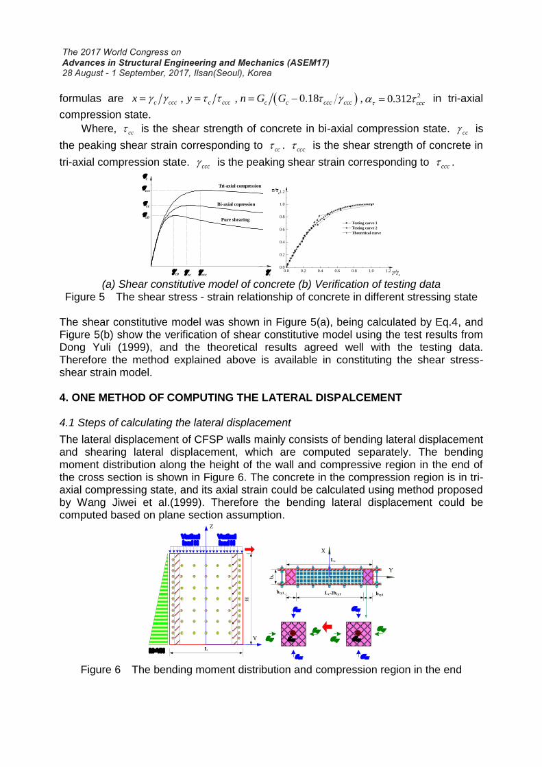
(a) Shear constitutive model of concrete (b) Verification of testing data
Figure 5 The shear stress - strain relationship of concrete in different stressing state
The shear constitutive model was shown in Figure 5(a), being calculated by Eq.4, and Figure 5(b) show the verification of shear constitutive model using the test results from Dong Yuli (1999), and the theoretical results agreed well with the testing data. Therefore the method explained above is available in constituting the shear stress-shear strain model. 4. ONE METHOD OF COMPUTING THE LATERAL DISPALCEMENT 4.1 Steps of calculating the lateral displacement
The lateral displacement of CFSP walls mainly consists of bending lateral displacement and shearing lateral displacement, which are computed separately. The bending moment distribution along the height of the wall and compressive region in the end of the cross section is shown in Figure 6. The concrete in the compression region is in tri-axial compressing state, and its axial strain could be calculated using method proposed by Wang Jiwei et al.(1999). Therefore the bending lateral displacement could be computed based on plane section assumption.
Figure 6 The bending moment distribution and compression region in the end
c
c
Tri-axial compression
Bi-axial copression
Pure shearing
c0
cc
ccc
ccc
cc
c0
0.0 0.2 0.4 0.6 0.8 1.0 1.20.0
0.2
0.4
0.6
0.8
1.0
1.2
Testing curve 1
Testing curve 2
Theoretical curve
τ/τc
γ/γc
L
H
Z
Y
Vertical
load N
M=VH
X
Y
Lc
bc
Lc-2bcy1bcy1 bcy1
σcz
σcx
σcy
σcx
σcyεcz
εcy
εcx
εcy
εcx
Vertical
load N

On the basis of the shearing strain-shearing stress model, the shearing lateral displacement could be simply computed and the lateral displacement of CFSP walls is obtained as shown in Figure 7.
Figure 7 The lateral displacement of CFSP walls
4.2 Validation of the theoretical method According to the methods above, the whole curves of lateral displacement are calculated and the curves are compared with the testing results, as shown in Figure.8. The calculating curves agreed well with the testing curves, which contain the descending part of the curve.
Figure 8 Comparison between theoretical results and testing results
5. CONCLUSIONS AND SUGGESTIONS (1) The method proposed in this paper can be used to calculate the shear stress- shear strain relationship curves and the results agreed well with the pure shear testing curves in its ascending for concrete. The pure shear testing results in the descending part of the curves.
-30 -20 -10 0 10 20 30
-450
-300
-150
0
150
300
450 SC1-EXP
SC1-THE V/K
N
/mm-30 -20 -10 0 10 20 30
-450
-300
-150
0
150
300
450 SC2-EXP
SC2-THEV
/KN
/mm
-24 -16 -8 0 8 16 24
-450
-300
-150
0
150
300
450 SC3-EXP
SC3-THE V/K
N
/mm-24 -16 -8 0 8 16 24
-400
-200
0
200
400 SC4-EXP
SC4-THE V/K
N
/mm

(2)The developed method can be used to predict the lateral load-carrying capacity-lateral displacement curves of the CFSP walls with a reasonable degree of accuracy. (3)Further research for the developed method considering the effect of initial imperfection, buckling of the steel plate and slip displacement between steel plate and concrete is required to improve the method. ACKNOWLEDGEMENT The authors acknowledge support from Taishan Scholar Priority Discipline Talent Group program funded by the Shan Dong Province. REFERENCES Wright H D and Gallocher S.C.(1995), “The behavior of composite walling under
construction and service loading”, Journal of Constructional Steel Research, 35 (3): 257-273.
Emori K.(2002) , “Compressive and shear strength of concrete filled steel box wall”, Steel Structures, 68 (2) : 29-40.
Anwar Hossain KM, Wright H D(2004), “Experimental and theoretical behaviour of composite walling under in-plane shear”, Journal of Constructional Steel Research, 60 (1): 59-83.
Tae-Sung E. Hong-Gun P. and Cheol-Ho L. et al(2009). “Behavior of Double Skin Composite Wall Subjected to In-Plane Cyclic Loading”, Journal of Structural Engineering, 135(10):1239-1249.
Nie Jian-Guo, Xiao-Wei Ma and Mu-Xuan Tao(2014), “Effective stiffness of composite shear wall with double plates and filled concrete”, Journal of Constructional Steel Research, 99(3):140-148.
Rafiei S, Hossain K M A, Lachemi M, et al. (2015), “Profiled sandwich composite wall with high performance concrete subjected to monotonic shear”,Engineering Structures, 107(2):124-136.
Zhou D.Y., Liu L.F, Zhu L.M. (2016). “Lateral load-carrying capacity analyses of composite shear walls with double steel plates and filled concrete with binding bars”, Journal of Central South University, 23(8), 2083-2091.
Wang J.W., Wu H.C. and Wang H.(1999), “Study on 3-D Equivalent Uniaxial Strain-Stress Relation of Concrete”, Journal of Hohai University,27(04):20-23.(In Chinese)
Dong Y.L., Zhang H.Y and Zhong C.Y.(1999), “Study on stress-strain curves of concrete under shear loading”, Mechanics in Engineering, 21(6):35-37.


![Optimum tailor-welded blank design using deformation path ......deep-drawn tailor-welded blanks [8]. Valente et al. [9] investigates the influence of different finite element formulations](https://static.fdocuments.in/doc/165x107/60c4891e83279247c60b34bb/optimum-tailor-welded-blank-design-using-deformation-path-deep-drawn-tailor-welded.jpg)