Non-linear behaviour of concrete beams reinforced with ...
38
See discussions, stats, and author profiles for this publication at: https://www.researchgate.net/publication/337559511 Non-linear behaviour of concrete beams reinforced with GFRP and CFRP bars grouted in sleeves Article · November 2019 DOI: 10.1016/j.istruc.2019.10.013 CITATIONS 5 READS 212 6 authors, including: Some of the authors of this publication are also working on these related projects: Numerical analysis of break-off test method on concrete (Finished Project) View project Unsaturated soil mechanics View project Mostafa Kazemi University of Liège 12 PUBLICATIONS 101 CITATIONS SEE PROFILE Jie Li RMIT University 103 PUBLICATIONS 851 CITATIONS SEE PROFILE Soheil Jahandari Western Sydney University and ANJ Company 23 PUBLICATIONS 206 CITATIONS SEE PROFILE Mohammad Saberian RMIT University 42 PUBLICATIONS 494 CITATIONS SEE PROFILE All content following this page was uploaded by Soheil Jahandari on 27 November 2019. The user has requested enhancement of the downloaded file.
Transcript of Non-linear behaviour of concrete beams reinforced with ...

See discussions, stats, and author profiles for this publication at: https://www.researchgate.net/publication/337559511
Non-linear behaviour of concrete beams reinforced with GFRP and CFRP bars
grouted in sleeves
Article · November 2019
DOI: 10.1016/j.istruc.2019.10.013
CITATIONS
5READS
212
6 authors, including:
Some of the authors of this publication are also working on these related projects:
Numerical analysis of break-off test method on concrete (Finished Project) View project
Unsaturated soil mechanics View project
Mostafa Kazemi
University of Liège
12 PUBLICATIONS 101 CITATIONS
SEE PROFILE
Jie Li
RMIT University
103 PUBLICATIONS 851 CITATIONS
SEE PROFILE
Soheil Jahandari
Western Sydney University and ANJ Company
23 PUBLICATIONS 206 CITATIONS
SEE PROFILE
Mohammad Saberian
RMIT University
42 PUBLICATIONS 494 CITATIONS
SEE PROFILE
All content following this page was uploaded by Soheil Jahandari on 27 November 2019.
The user has requested enhancement of the downloaded file.

1
Non-linear behaviour of concrete beams reinforced with GFRP and CFRP
bars grouted in sleeves
Mostafa Kazemi1, Jie Li2, Salar Lahouti Harehdasht3, Negin Yousefieh4, Soheil Jahandari5,
Mohammad Saberian6
1- MSc Graduate, Department of Civil Engineering, University of Guilan, Rasht, Iran, E-mail:
2- Associate Professor, School of Engineering, RMIT University, Victoria, Australia, E-email:
3- MSc Graduate, Department of Civil Engineering, University of Guilan, Rasht, Iran, E-mail:
4- MSc Graduate, Department of Civil Engineering, University of Tehran, Tehran, Iran, E-mail:
5- Ph.D. Candidate, Center for Infrastructure Engineering, Western Sydney University, Sydney,,
Australia, E-mail: [email protected].
6- Ph.D. Candidate, School of Engineering, RMIT University, Melbourne, Victoria, Australia,
Eamil: [email protected].
2
Non-linear behaviour of concrete beams reinforced with GFRP and CFRP
bars grouted in sleeves
Mostafa Kazemi1, Jie Li2, Salar Lahouti Harehdasht3, Negin Yousefieh4, Soheil Jahandari5,
Mohammad Saberian6
Abstract
The low-quality bond between fibre reinforced polymer (FRP) bars and surrounding concrete has
drawn the attention of many researchers. The use of high-strength materials such as the grout in
the intersection of FRP bars and surrounding concrete can effectively prevent any slippage once
they are in contact and subsequently increase the bond quality. Therefore, this study was
numerically focused on the flexural behaviour of concrete beams reinforced with glass fibre
reinforced polymer (GFRP) and carbon fibre reinforced polymer (CFRP) bars, grouted only in
the pure bending zone and along the whole beam length. The numerical outputs revealed that the
grouted GFRP bars propagated the maximum principal stress in high-strength concrete beams,
but not as much as that in normal-strength concrete specimens. In addition, the stress distribution
in the grout, created only in the pure bending zone, was nearly constant at the ultimate moment.
For the grout, developed along the whole beam length, this stress increased by approaching the
mid-span of the concrete beam. Furthermore, at the ultimate moment, the tensile stress of 12-mm
diameter CFRP bars was about 3.5 times more than that of the 16-mm diameter CFRP bars,
leading to the generation of difference between failure modes of concrete specimens reinforced
with various diameters of CFRP bars.
Keywords: Flexural behaviour; pure bending zone; grouted FRP bars; FE analysis.
3
1. Introduction
Corrosion of steel reinforcement bars is known as one of the major causes of structural
deterioration, and it is estimated that about 4% of the gross domestic product of industrialized
countries is accounted for the cost of corrosion [1, 2]. One of the innovative solutions to reduce the
effect of corrosion in the tension region of concrete components is to replace the flexural steel bars
with fibre reinforced polymer (FRP) bars which can be considered as a viable substitute to the
other options in the construction sector [3-7]. Different types of FRP bars including carbon fibre
reinforced polymer (CFRP), glass fibre reinforced polymer (GFRP), and aramid fibre reinforced
polymer (AFRP) bars have been proposed by researchers due to some advantages including low
density, corrosion resistance, and high tensile strength [8-11].
Of all FRP composite materials, the GFRP flexural bar [12] has drawn the attention of
researchers owing to its corrosion resistance feature. Regarding this, the behaviour of concrete
specimens strengthened with steel transverse reinforcement and GFRP flexural reinforcement
was assessed with Khorasani et al. [13, 14]. They showed that the ultimate load of GFRP
strengthened concrete increased by increasing the level of concrete strength and the GFRP
reinforcement ratio. Meanwhile, the failure mode of the aforementioned composite components
with and without transverse reinforcement was found to be rupture and shear, respectively. A
similar study by Ashour [15] showed that the major diagonal crack was generated in the GFRP
reinforced concrete components with no stirrup at failure load and the type of failure mode was
shear. Another study by Ospina and Bakis [16] demonstrated that higher amount of the GFRP
flexural reinforcement ratio in concrete beams led to narrower crack widths. In addition, a
decrease in the bar diameter led to a lower tensile strength of GFRP bars [17].
The CFRP bar is proposed by researchers as another reinforcing material, having higher
chemical resistance and suitable tensile properties. Concerning this, Brozda et al. [18]
demonstrated that the tensile strength of CFRP bars, embedded in concrete elements, was found
to be very high and a linear elastic characteristic was observed for CFRP bars until rupture. El-
Hacha and Gaafar [19] assessed the performance of concrete beams strengthened with a 9-mm
diameter CFRP bar. According to the outputs, the use of CFRP bar effectively led to an increase
in the load-bearing capacity and delaying the opening new cracks in the concrete beams until
ultimate load. A study by Rafi et al. [20] showed that a negligible difference appeared between
the cracking pattern of concrete beams strengthened with CFRP and steel bars. Meanwhile,

4
concrete specimen strengthened with 9.5-mm diameter CFRP bar had high deformability factors,
demonstrating its ductile nature of failure. Recently, Mustafa and Hassan [21] evaluated the
influence of various diameters of CFRP flexural reinforcement on the failure mode of concrete
beams. The results showed that these components strengthened with CFRP bars with the
diameters of 16, 18, 20 and 22 mm were failed by concrete crushing rather than by rupture FRP
reinforcement.
Apart from some advantages of FRP bars, the bond quality at the interface between concrete
materials and FRP reinforcement is not as much as that of the concrete materials and
conventional steel bars. So, the substitution of steel bar with FRP bars in concrete members
causes to generate larger deflections, leading to wider cracks in the tension zone owing to the
low elastic modulus of FRP materials [22, 23]. This bond quality at the interface between FRP
bars and concrete members can be somewhat improved by partial replacement of normal-strength
concrete materials with the high-strength cement grout, surrounding the FRP bars [23-25]. Dong et
al. [26] assessed the bendability of concrete components strengthened with CFRP and GFRP bars
embedded in the grout. They showed that the utilization of high-strength cement grout, holding
GFRP and CFRP bars, decreased crack widths and improved the serviceability behaviour of
concrete beams. It can be stated that previous studies have mainly focused on experimentally
evaluating the flexural behaviour of concrete components strengthened with FRP bars grouted in
sleeves. To get a better understanding of the non-linear behaviour of FRP-strengthened concrete
specimens, the participation of transverse and flexural reinforcement, grout and concrete
components in carrying different amounts of loading is required to be assessed numerically in
details. Meanwhile, the level of concrete strength can affect the stress distribution in these
specimens. Therefore, for further investigation, the flexural performance of concrete beams
reinforced with GFRP and CFRP bars grouted in sleeves was numerically analyzed at nominal
and ultimate moments in this study, where the contour plots of the stress distribution showed
how different components of FRP-reinforced concrete beams participated in carrying the
generated stress intensity. In addition, the non-linear behaviour of the grout, surrounding the FRP
bars within the pure bending zone and along the whole beam length was effectively analyzed at
nominal and ultimate moments using the contour plots of damage variable and stress distribution,
which played a key role in the bending behaviour of FRP-reinforced concrete beams.
Furthermore, the results also provided a comparison between the CFRP and GFRP bars’ abilities
5
to participate in the distribution of maximum tensile stress along the beam length, where the
effect of GFRP and CFRP reinforcement ratio on the failure mode was analyzed. Meanwhile, the
influence of normal- and high-strength concrete on the stress distribution and load-bearing
capacity of FRP reinforced concrete beams was assessed. Generally, the interaction between
different components of FRP-reinforced concrete beams within the pure bending zone and along
the whole beam length was numerically evaluated and the results were compared to each other.
2. FE modeling
2.1. Material properties and numerical models
To model the concrete components strengthened by steel flexural bar and GFRP and CFRP
composite bars, the ABAQUS software was employed in this study. The mechanical properties
of conventional steel and GFRP and CFRP bars are presented in Table 1. The Poisson’s ratio for
all of the flexural bars was considered to be equal to 0.3, as suggested by other researchers [27,
28]. The experimental outputs, given by Dong et al. [26], were used to verify the numerical
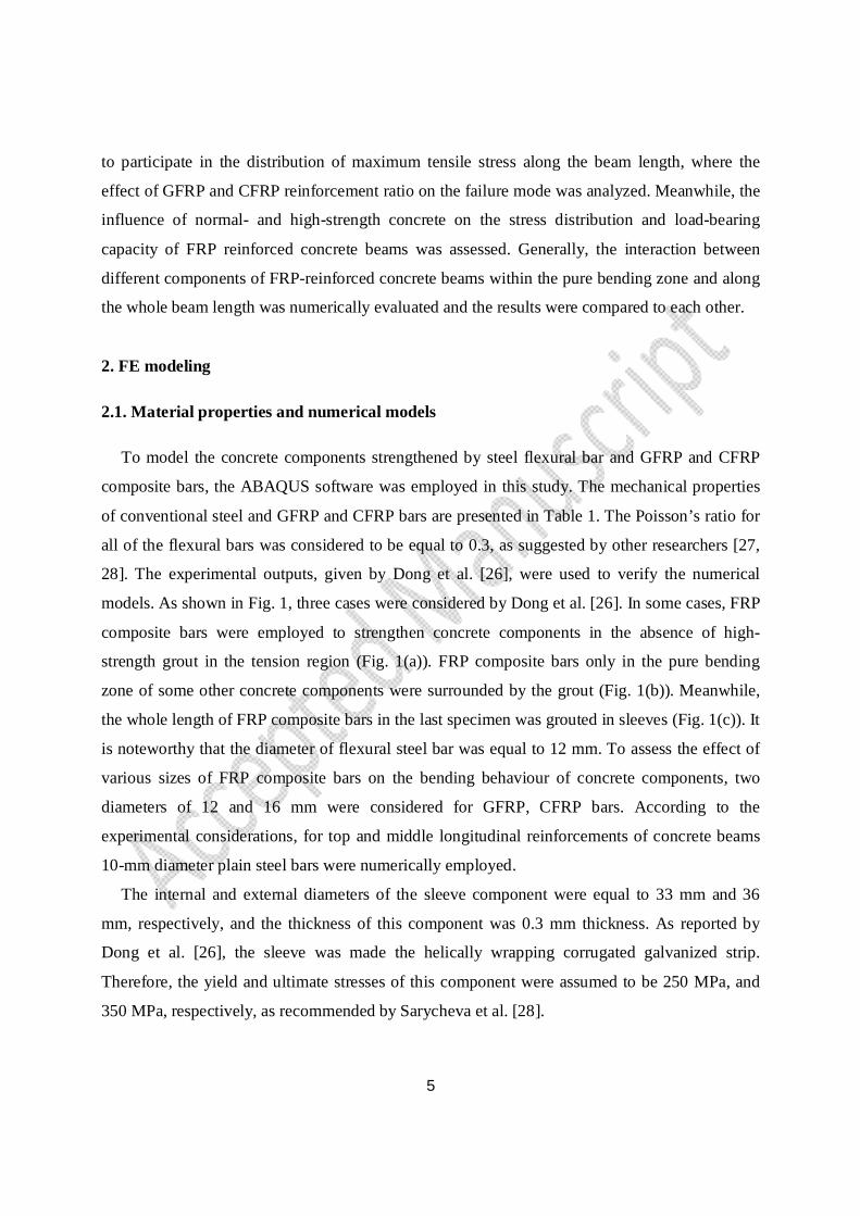
models. As shown in Fig. 1, three cases were considered by Dong et al. [26]. In some cases, FRP
composite bars were employed to strengthen concrete components in the absence of high-
strength grout in the tension region (Fig. 1(a)). FRP composite bars only in the pure bending
zone of some other concrete components were surrounded by the grout (Fig. 1(b)). Meanwhile,
the whole length of FRP composite bars in the last specimen was grouted in sleeves (Fig. 1(c)). It
is noteworthy that the diameter of flexural steel bar was equal to 12 mm. To assess the effect of
various sizes of FRP composite bars on the bending behaviour of concrete components, two
diameters of 12 and 16 mm were considered for GFRP, CFRP bars. According to the
experimental considerations, for top and middle longitudinal reinforcements of concrete beams
10-mm diameter plain steel bars were numerically employed.
The internal and external diameters of the sleeve component were equal to 33 mm and 36
mm, respectively, and the thickness of this component was 0.3 mm thickness. As reported by
Dong et al. [26], the sleeve was made the helically wrapping corrugated galvanized strip.
Therefore, the yield and ultimate stresses of this component were assumed to be 250 MPa, and
350 MPa, respectively, as recommended by Sarycheva et al. [28].
6
Generally, 12 concrete beams were modeled and reinforced with different diameters of steel,
GFRP, and CFRP bars (Table 2). Among these concrete components, 10 normal-strength
concrete beams (30 MPa) were verified with experimental data given by Dong et al. [26]. After
verifying the numerical models of G12-P and G12-W, the mechanical properties of normal-
strength concrete were replaced with those of high-strength concrete to assess the influence of
high-strength concrete (60 MPa) on the non-linear behaviour of beam strengthened with grouted
GFRP bars (G12-P-H and G12-W-H). It is noteworthy that GFRP flexural bars in the G12-P-H
specimen were grouted in sleeves only in the pure bending zone, while GFRP flexural bars in the
G12-W-H specimen were grouted along the whole length of the beam.
In all numerical models, the compressive strength of grout was assumed to be 60 MPa,
similarly to what was obtained from 40×40×160mm prisms as reported by Dong et al. [26].
Meanwhile, the corresponding strength for the normal- and high-strength concrete was equal to
30 MPa and 60 MPa, respectively. The elastic modulus of concrete materials was calculated
using the Eq. 1 as suggested by Hognestad [29].
E = 4700 f (1)
Where E and f were the elastic modulus and compressive strength of concrete materials in
MPa, respectively. Therefore, the elastic modulus of the grout was assumed to be 36400 MPa.
Meanwhile, this value for the normal- and high-strength concrete was 25700 MPa and 36400
MPa, respectively. On the other hand, the peak strain of concrete and grout in this study was
assumed to be 0.0035 at the most as recommended by Hognestad [29].
7
Fig. 1. Reinforcing bars details of concrete components strengthened with conventional steel or
FRP composite bars (a); the grouted FRP composite bars only in the pure bending region (b); and
wholly grouted FRP composite bars [26].
Table 1. Mechanical properties of steel, GFRP, and CFRP bars.
Type of
the bar
Dimeter of bar
(db ) (mm)
Area of flexural
bar (Af) (mm )
Yield Stress
(fy) (MPa)
Ultimate stress
(ffu) (MPa)
Modulus of Elasticity
(Ef) (GPa) Poisson Ratio
Steel 10 78.5 350 - 195 0.3
16 201.1 449 - 197 0.3
GFRP 12 113.1 - 947 45.4 0.3
16 201.1 - 889 46.4 0.3
CFRP 12 113.1 - 1890 136.4 0.3
16 201.1 - 1600 127.6 0.3 e Modulus of Elasticity

8
Table 2. Details of reinforced concrete beams.
Specimens Flexural reinforcement
퐴 Ef (MN) d a (mm) Transverse
reinforcement Type Amount
Sb16 Steel 2∅16 39.6 357 ∅10@100
Gc12-Nd
GFRP
2∅12 5.1 359 ∅10@100
G12-Pe 2∅12 5.1 347 ∅10@100
G12-Wf 2∅12 5.1 347 ∅10@100
G12-P-Hg 2∅12 5.1 347 ∅10@100
G12-W-H 2∅12 5.1 347 ∅10@100
G16-N 2∅16 9.3 357 ∅10@100
G16-P 2∅16 9.3 347 ∅10@100
Ch12-N
CFRP
2∅12 15.4 359 ∅10@100
C12-P 2∅12 15.4 347 ∅10@100
C16-N 2∅16 25.7 357 ∅10@100
C16-P 2∅16 25.7 347 ∅10@100 a Distance from extreme compression fibre to centroid of tension reinforcement b Steel bar c GFRP bar d Specimen with FRP bars e Specimen strengthened with grouted FRP composite bars only in the pure bending region f Specimen strengthened with wholly grouted FRP composite bars g High-strength concrete specimen h CFRP bar
2.2. Concrete Damaged Plasticity Model
In ABAQUS software, the crack model of concrete damaged plasticity (CDP) was used to
analyze both non-linear compressive and tensile behaviours of concrete beams [30, 31] (Fig. 2).
Eqs. (1) and (2) show the relationships between the stress and strain of concrete to develop the
CDP model at tension and compression.
σ = (1− d )E˳(ε − ε ) (1)
σ = (1− d )E˳(ε − ε ) (2)

9
Where E is the Young’s modulus of concrete, d and d are compressive damage variable
(DAMAGEC) and tensile damage variable (DAMAGET), respectively, and ε and ε are
equivalent plastic strains at compression and tension, respectively [32].
Some parameters were considered in ABAQUS software to develop the CDP model. One of
these parameters was the viscosity parameter (μ). This parameter permits to moderately exceed
the plastic potential surface area in certain sufficiently small problem steps. Thus, it needs to
arrange the value of viscosity parameter a few times to specify its effects on the problem solution
result in ABAQUS and to suitably select a minimum value of μ. By considering this, a very
small number was assumed for μ as suggested by other researchers [31, 33, 34]. The behavior of
concrete under compound stress can be determined using the parameter of dilation angle (ψ).
This parameter was considered to be 31 degrees as recommended by Szczecina and Winnicki
[35]. Another parameter is the modification coefficient of the deviatoric plane (Kc), which can be
controlled by the utilization of the Drucker-Prager yield criterion to assume the yielding pattern
for stress-strain curves of concrete [36]. According to Fig. 3, the failure surface in the deviatoric
cross section can be controlled using Kc and it is not required to be considered a perfect circle as
shown in Fig. 3. As suggested by other researchers [37], Kc can be in the range of 0.5-1.
Therefore, the value of 0.667 was assumed for this parameter in the CDP model. σb0/σc0 is the
ratio of initial biaxial compressive yield stress to initial uniaxial compressive yield stress. As
recommended in the ABAQUS user’s manual [31], the amount of 1.16 was considered for this
ratio. The ratio of tensile to compressive strength is introduced as the parameter of flow potential
eccentricity (ε) in the CDP model. As suggested by other researchers [33, 34], the value of 0.1
was introduced to the software for this parameter.

10
(a) (b)
Fig. 2. Proposed non-linear tensile (a) and compressive (b) behaviours of concrete component,
employed in ABAQUS.
Fig. 3. Yield patterns obtained by utilizing Drucker-Prager yield criterion to control Kc values.

11
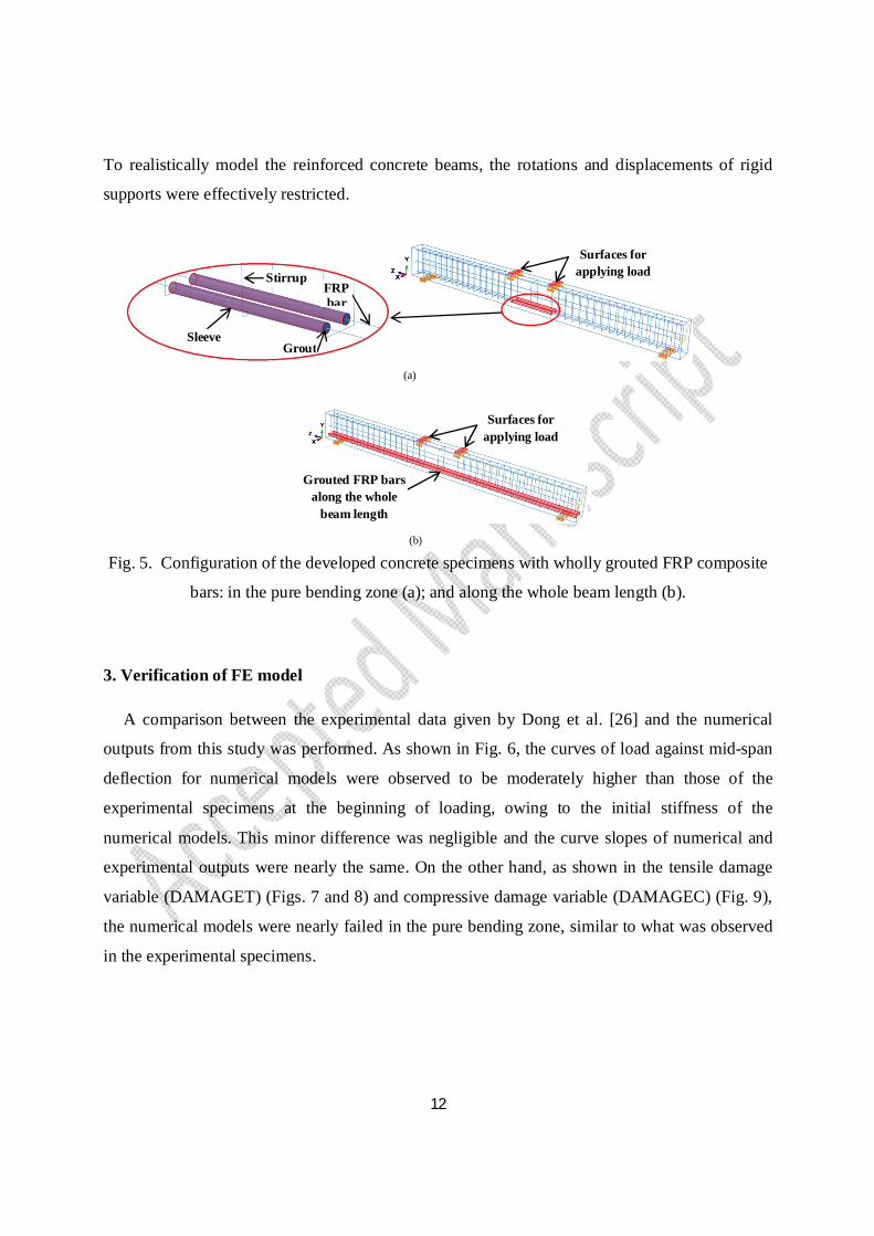
2.3. Components of numerical models and features of element type
Figs. 4 and 5 show the components of numerical models including two rigid sections as
supports, two other rigid sections as load cells, a concrete beam, grout, sleeve, stirrups, steel, and
GFRP and CFRP bars. To model stirrups, steel, and GFRP and CFRP bars, the element type of
3D deformable wire (truss element) was employed. In addition, as recommended by other
researchers [33, 38, 39, 40, 41, 42], the element type of three-dimensional (3D) hexahedral
element, with 8 nodes and reduced integration (C3D8R) was used to simulate the concrete beam,
grout, sleeve, and rigid sections.
Suitable mesh sizes were introduced to each reinforced concrete beam. For S16, G12-N, G12-
P, G12-W, G12-P-H, G12-W-H, G16-N, G16-P, C12-N, C12-P, C16-N and C16-P, the
approximate element sizes of 90, 110, 110, 100, 100, 110, 110, 90, 110, 110, 90 and 110 mm,
respectively, were introduced to longitudinal steel and FRP bars. The same element sizes were
considered for the pure bending zone of concrete beams in the longitudinal direction. The
approximate element size of 120 mm was considered for other parts of concrete beams in the
aforementioned direction. The mesh size of transverse reinforcement was assumed to be 40 mm
for all concrete beams.
Fig. 4. FE mesh of the reinforced concrete beam.
2.3. Loading pattern, surface interaction and boundary condition
The constraint of tie was introduced to the intersection of sleeves and grout. The same
constraint was used in the intersection between the load cells and concrete beam. When
surrounded by the grout, FRP bars can be considered to be embedded in the grout. Thereafter, all
bars, stirrups, sleeves, and grout were embedded in the concrete beam. The surface to surface
contact was utilized to define the intersection between supports and concrete component in
which no slip happened once points were in contact. Fig. 5 shows the surfaces for applying load.
Load cells
Supports
12
To realistically model the reinforced concrete beams, the rotations and displacements of rigid
supports were effectively restricted.
(a)
(b)
Fig. 5. Configuration of the developed concrete specimens with wholly grouted FRP composite
bars: in the pure bending zone (a); and along the whole beam length (b).
3. Verification of FE model
A comparison between the experimental data given by Dong et al. [26] and the numerical
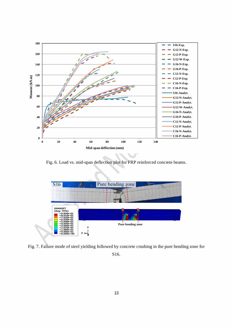
outputs from this study was performed. As shown in Fig. 6, the curves of load against mid-span
deflection for numerical models were observed to be moderately higher than those of the
experimental specimens at the beginning of loading, owing to the initial stiffness of the
numerical models. This minor difference was negligible and the curve slopes of numerical and
experimental outputs were nearly the same. On the other hand, as shown in the tensile damage
variable (DAMAGET) (Figs. 7 and 8) and compressive damage variable (DAMAGEC) (Fig. 9),
the numerical models were nearly failed in the pure bending zone, similar to what was observed
in the experimental specimens.
Surfaces for applying load
GroutSleeve
Surfaces for applying load
Grouted FRP bars along the whole
beam length
FRP bar
Stirrup
13
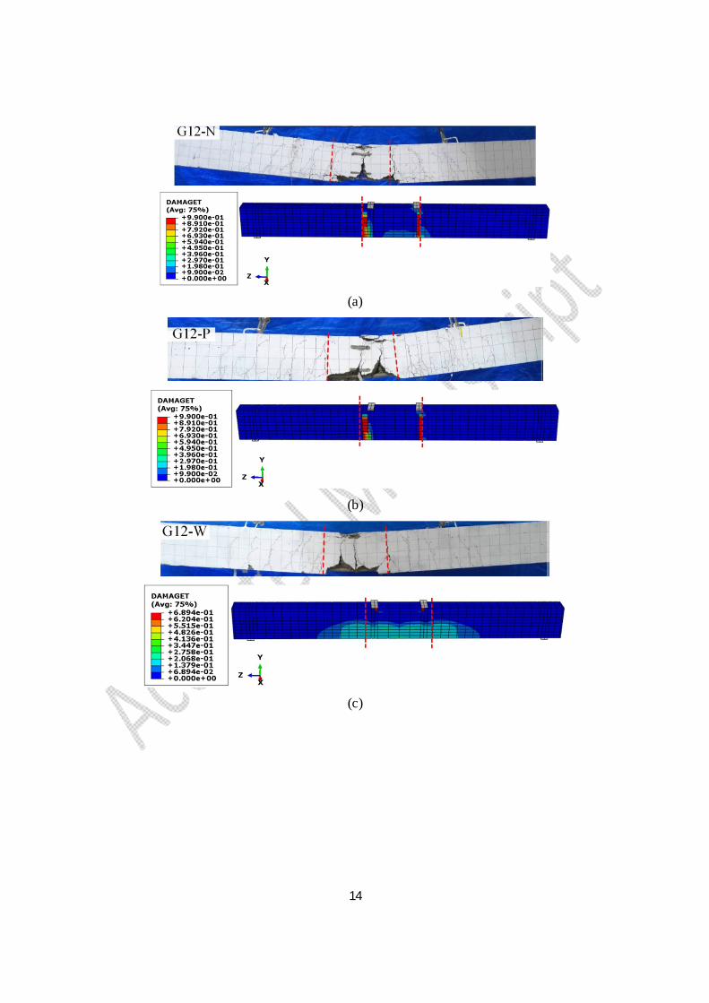
Fig. 6. Load vs. mid-span deflection plot for FRP reinforced concrete beams.
Fig. 7. Failure mode of steel yielding followed by concrete crushing in the pure bending zone for
S16.
0
20
40
60
80
100
120
140
160
180
0 20 40 60 80 100 120 140
S16-Exp.G12-N-Exp.G12-P-Exp.G12-W-Exp.G16-N-Exp.G16-P-Exp.C12-N-Exp.C12-P-Exp.C16-N-Exp.C16-P-Exp.S16-Analyt.G12-N-Analyt.G12-P-Analyt.G12-W-Analyt.G16-N-Analyt.G16-P-Analyt.C12-N-Analyt.C12-P-Analyt.C16-N-Analyt.C16-P-Analyt.
Mid-span deflection (mm)
Mom
ent (
kN.m
)
Pure bending zone
14
(a)
(b)
(c)
15
(d)
(e)
(f)
16
(g)
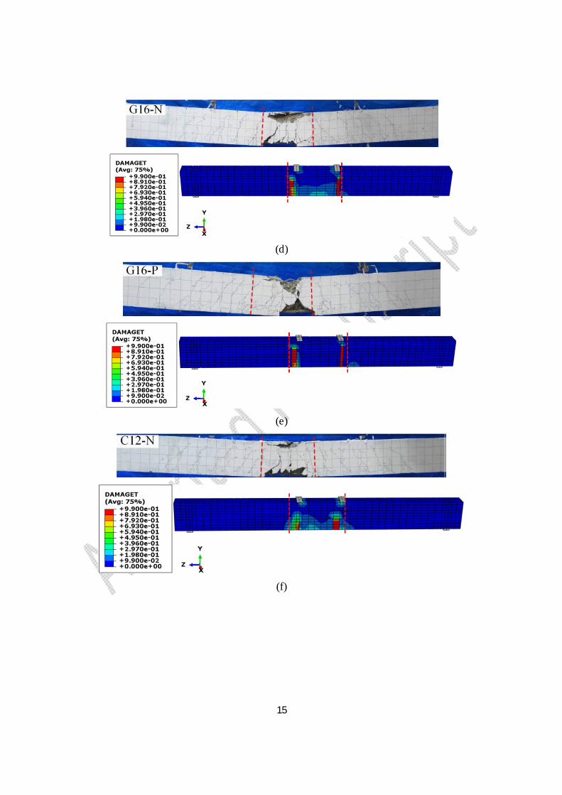
Fig. 8. Failure mode of concrete crushing followed by rupture of FRP bars in the pure bending
zone for G12-N (a); G12-P (b); G12-W (c); G16-N (d); G16-P (e); C12-N (f); C12-P (g).
(a)
(b)

17
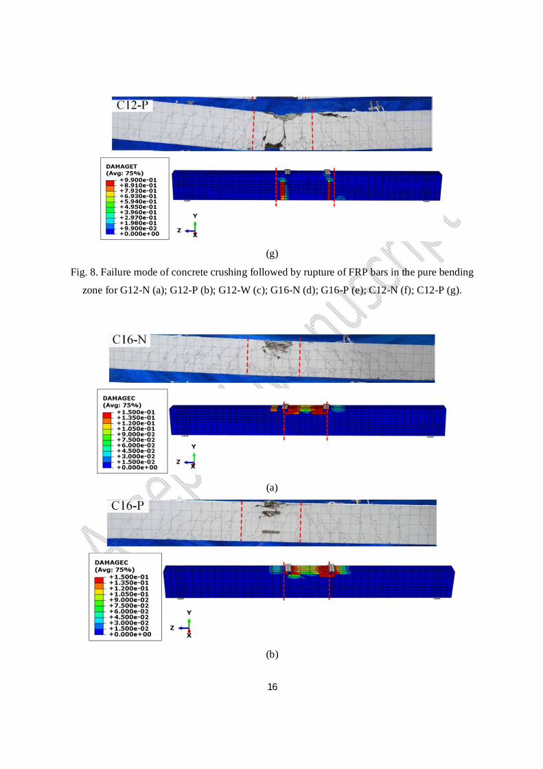
Fig. 9. Failure mode of concrete crushing without rupture of CFRP bars in the pure bending zone
for C16-N (a); C16-P (b).
4. Results and discussions on FE analysis
According to the results, the difference between the ultimate mid-span deflection of
experimental and numerical models was negligible as shown in Fig. 6. In Table 3, the values of
moments, obtained by Dong et al. [26], are presented for different experimental specimens. The
ultimate moments of S16, G12-N, G12-P, G12-W, G16-N, G16-P, C12-N, C12-P, C16-N and
C16-P in this numerical study were respectively obtained by 2.1%, 2.6%, 2.1%, 1.3%, 2.1%,
4.2%, 5.5%, 4.7%, 8.7% and 1.7% more than those in the experimental results given by Dong et
al. [26].
Table 3. Nominal and ultimate moments of reinforced concrete beams given by Dong et al. [26].
Specimens Mn
a
(kN.m)
Mub
(kN.m) Mu/Mn
S16 74.7 - -
G12-N 72.8 91.7 1.26
G12-P 74.6 98.3 1.32
G12-W 74.2 98.4 1.33
G16-N 100.2 124.6 1.24
G16-P 101.5 108.8 1.07
C12-N 118.6 123.6 1.04
C12-P 119.8 142 1.19
C16-N 146.2 158.9 1.09
C16-P 140.9 156 1.11 a Nominal moment b Ultimate moment
The numerical results provided more descriptions about the failure mechanism, load-bearing
capacity and stress distribution of developed models. Meanwhile, the plots of tensile damage
18
variable (DAMAGET) (Figs. 7 and 8) and compressive damage variable (DAMAGEC) (Fig. 9)
were employed to analyze the failure mechanisms of numerical models. In addition, the stress
distribution of reinforced concrete models was assessed at nominal and ultimate moments. To
realistically predict the non-linear behaviour of ductile and brittle materials, the von Mises stress
and the maximum principal stress were used in ABAQUS software as proposed by other
researchers [42, 43]. Therefore, the contour plots of S, Mises and maximum principal stress were
utilized to analyze the stress distribution in reinforcement and concrete element, respectively.
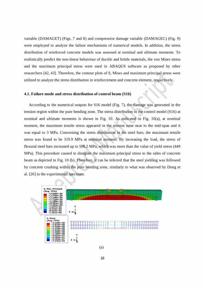
4.1. Failure mode and stress distribution of control beam (S16)
According to the numerical outputs for S16 model (Fig. 7), the damage was generated in the
tension region within the pure bending zone. The stress distribution in the control model (S16) at
nominal and ultimate moments is shown in Fig. 10. As indicated in Fig. 10(a), at nominal
moment, the maximum tensile stress appeared in the tension zone near to the mid-span and it
was equal to 3 MPa. Concerning the stress distribution in the steel bars, the maximum tensile
stress was found to be 319.9 MPa at nominal moment. By increasing the load, the stress of
flexural steel bars increased up to 508.2 MPa, which was more than the value of yield stress (449
MPa). This procedure caused to dissipate the maximum principal stress to the sides of concrete
beam as depicted in Fig. 10 (b). Therefore, it can be inferred that the steel yielding was followed
by concrete crushing within the pure bending zone, similarly to what was observed by Dong et
al. [26] in the experimental specimen.
(a)
19
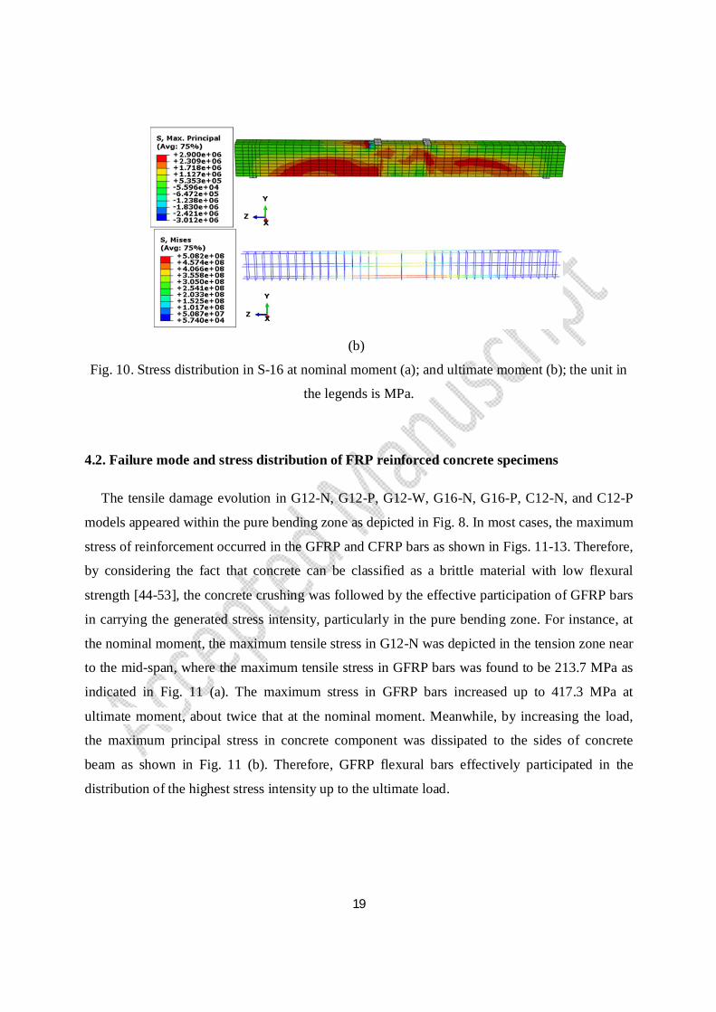
(b)
Fig. 10. Stress distribution in S-16 at nominal moment (a); and ultimate moment (b); the unit in
the legends is MPa.
4.2. Failure mode and stress distribution of FRP reinforced concrete specimens
The tensile damage evolution in G12-N, G12-P, G12-W, G16-N, G16-P, C12-N, and C12-P
models appeared within the pure bending zone as depicted in Fig. 8. In most cases, the maximum
stress of reinforcement occurred in the GFRP and CFRP bars as shown in Figs. 11-13. Therefore,
by considering the fact that concrete can be classified as a brittle material with low flexural
strength [44-53], the concrete crushing was followed by the effective participation of GFRP bars
in carrying the generated stress intensity, particularly in the pure bending zone. For instance, at
the nominal moment, the maximum tensile stress in G12-N was depicted in the tension zone near
to the mid-span, where the maximum tensile stress in GFRP bars was found to be 213.7 MPa as
indicated in Fig. 11 (a). The maximum stress in GFRP bars increased up to 417.3 MPa at
ultimate moment, about twice that at the nominal moment. Meanwhile, by increasing the load,
the maximum principal stress in concrete component was dissipated to the sides of concrete
beam as shown in Fig. 11 (b). Therefore, GFRP flexural bars effectively participated in the
distribution of the highest stress intensity up to the ultimate load.

20
(a)
(b)
Fig. 11. Stress distribution in G12-N at nominal moment (a); and ultimate moment (b); the unit
in the legends is MPa.
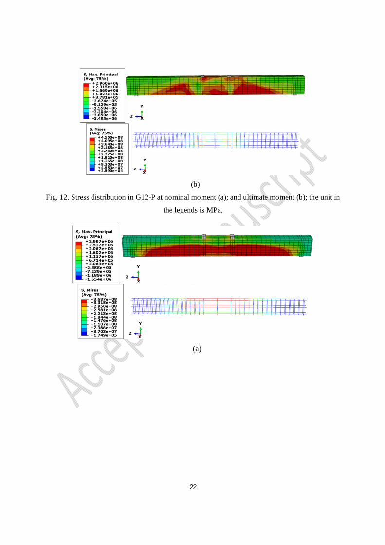
4.2.1. A comparison between the FRP composite bars in the pure bending region and along
the whole beam length
There was no significant difference between the failure mode of concrete member
strengthened with FRP bars grouted in the pure bending zone and along the whole beam length
(G12-P and G12-W) as indicated in Fig. 8. However, a comparison between the stress
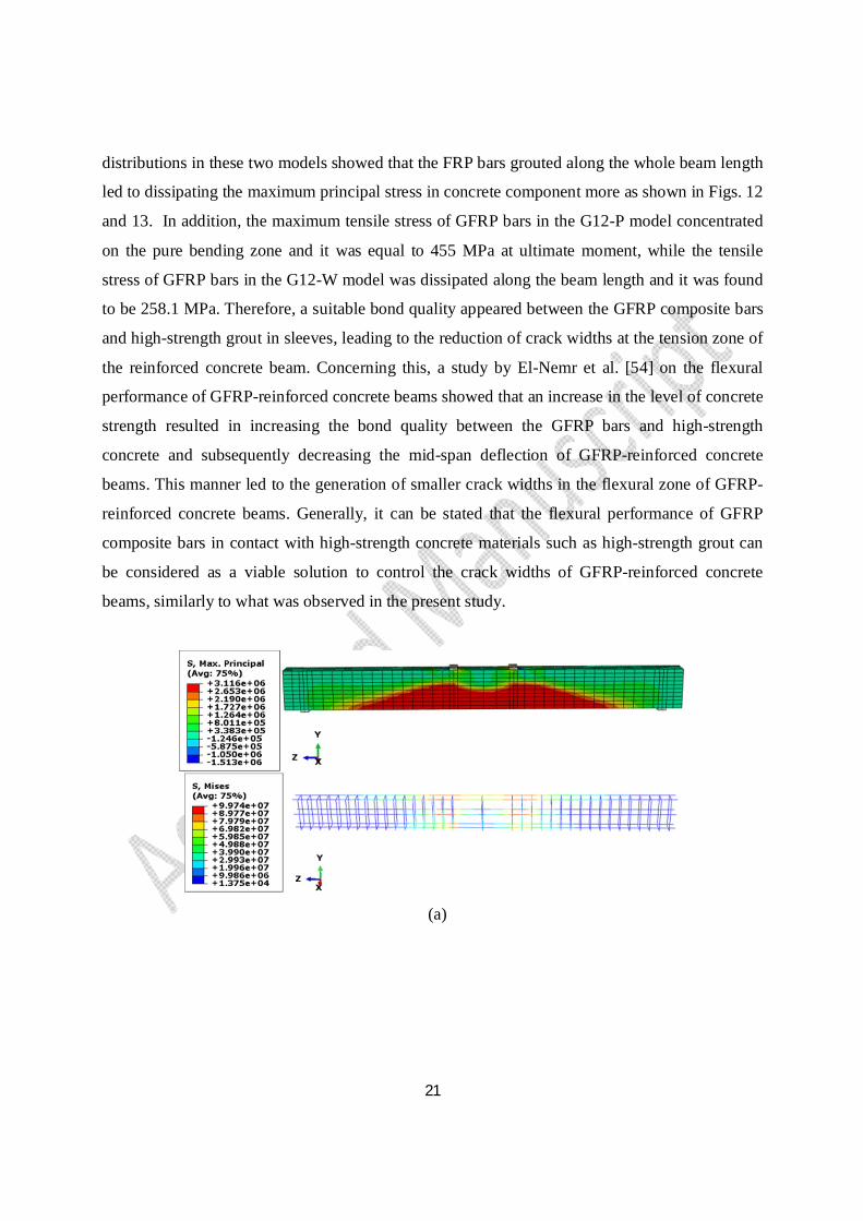
21
distributions in these two models showed that the FRP bars grouted along the whole beam length
led to dissipating the maximum principal stress in concrete component more as shown in Figs. 12
and 13. In addition, the maximum tensile stress of GFRP bars in the G12-P model concentrated
on the pure bending zone and it was equal to 455 MPa at ultimate moment, while the tensile
stress of GFRP bars in the G12-W model was dissipated along the beam length and it was found
to be 258.1 MPa. Therefore, a suitable bond quality appeared between the GFRP composite bars
and high-strength grout in sleeves, leading to the reduction of crack widths at the tension zone of
the reinforced concrete beam. Concerning this, a study by El-Nemr et al. [54] on the flexural
performance of GFRP-reinforced concrete beams showed that an increase in the level of concrete
strength resulted in increasing the bond quality between the GFRP bars and high-strength
concrete and subsequently decreasing the mid-span deflection of GFRP-reinforced concrete
beams. This manner led to the generation of smaller crack widths in the flexural zone of GFRP-
reinforced concrete beams. Generally, it can be stated that the flexural performance of GFRP
composite bars in contact with high-strength concrete materials such as high-strength grout can
be considered as a viable solution to control the crack widths of GFRP-reinforced concrete
beams, similarly to what was observed in the present study.
(a)
22
(b)
Fig. 12. Stress distribution in G12-P at nominal moment (a); and ultimate moment (b); the unit in
the legends is MPa.
(a)
23
(b)
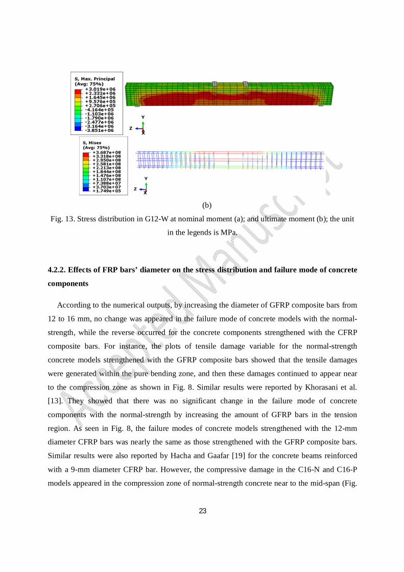
Fig. 13. Stress distribution in G12-W at nominal moment (a); and ultimate moment (b); the unit
in the legends is MPa.
4.2.2. Effects of FRP bars’ diameter on the stress distribution and failure mode of concrete
components
According to the numerical outputs, by increasing the diameter of GFRP composite bars from
12 to 16 mm, no change was appeared in the failure mode of concrete models with the normal-
strength, while the reverse occurred for the concrete components strengthened with the CFRP
composite bars. For instance, the plots of tensile damage variable for the normal-strength
concrete models strengthened with the GFRP composite bars showed that the tensile damages
were generated within the pure bending zone, and then these damages continued to appear near
to the compression zone as shown in Fig. 8. Similar results were reported by Khorasani et al.
[13]. They showed that there was no significant change in the failure mode of concrete
components with the normal-strength by increasing the amount of GFRP bars in the tension
region. As seen in Fig. 8, the failure modes of concrete models strengthened with the 12-mm
diameter CFRP bars was nearly the same as those strengthened with the GFRP composite bars.
Similar results were also reported by Hacha and Gaafar [19] for the concrete beams reinforced
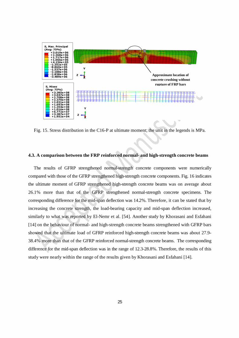
with a 9-mm diameter CFRP bar. However, the compressive damage in the C16-N and C16-P
models appeared in the compression zone of normal-strength concrete near to the mid-span (Fig.

24
9). Concerning this, Mustafa and Hassan [21] showed that the concrete components strengthened
with the CFRP composite bars with the diameters of 16, 18, 20 and 22 mm were failed by
concrete crushing rather than by rupture FRP reinforcement. According to the mechanical
properties of CFRP bars presented in Table 1, the axial stiffness (EfAf) of 16-mm diameter CFRP
bars was found to be 10.3 MN more than that of the 12-mm diameter CFRP bars. Therefore, an
increase in the reinforcement ratio of the CFRP bars led to a reduction in the mid-span deflection
and a subsequent generation of concrete crushing in the compression zone of normal-strength
concrete without rupture of the CFRP bars. Similar results were also observed in the plots of
stress distribution. As shown in Fig. 14, for the C12-P model, the maximum principal stress
occurred in the tension zone, where the tensile stress of 12-mm diameter CFRP bars was found
to be high (851.1 MPa) at ultimate moment. However, for the C16-P model, the approximate
location of the maximum principal stress appeared in the compression zone of normal-strength
concrete near to the mid-span, while low tensile stress was obtained for the 16-mm diameter
CFRP bars (237 MPa) at the ultimate moment as shown in Fig. 15. Therefore, the CFRP flexural
bars with a diameter of 16 mm slightly participated in carrying some of the generated stress
intensity.
Fig. 14. Stress distribution in the C12-P at ultimate moment; the unit in the legends is MPa.
Approximate location of concrete crushing followed
by rupture of FRP bars
25
Fig. 15. Stress distribution in the C16-P at ultimate moment; the unit in the legends is MPa.
4.3. A comparison between the FRP reinforced normal- and high-strength concrete beams
The results of GFRP strengthened normal-strength concrete components were numerically
compared with those of the GFRP strengthened high-strength concrete components. Fig. 16 indicates
the ultimate moment of GFRP strengthened high-strength concrete beams was on average about
26.1% more than that of the GFRP strengthened normal-strength concrete specimens. The
corresponding difference for the mid-span deflection was 14.2%. Therefore, it can be stated that by
increasing the concrete strength, the load-bearing capacity and mid-span deflection increased,
similarly to what was reported by El-Nemr et al. [54]. Another study by Khorasani and Esfahani
[14] on the behaviour of normal- and high-strength concrete beams strengthened with GFRP bars
showed that the ultimate load of GFRP reinforced high-strength concrete beams was about 27.9-
38.4% more than that of the GFRP reinforced normal-strength concrete beams. The corresponding
difference for the mid-span deflection was in the range of 12.3-28.8%. Therefore, the results of this
study were nearly within the range of the results given by Khorasani and Esfahani [14].
Approximate location of concrete crushing without
rupture of FRP bars

26
Fig. 16. Load against mid-span deflection of normal- and high-strength concrete models.
Figs. 17 and 18 show that the maximum tensile stress in the concrete component was in the
range of 6-6.6 MPa. This stress appeared near to the tension zone of high-strength concrete
beams (Figs. 17 and 18), and the general trend of stress distribution was nearly the same
observed in the normal-concrete strength concrete beams (Figs. 12 and 13). In addition, it seems
that the GFRP bars grouted in the pure bending zone and along the whole beam length dissipated
the maximum principal stress in the high-strength concrete beams at nominal and ultimate
moments (Figs. 17 and 18), but not as much as that in the normal-strength concrete beams (Figs.
12 and 13).
0
20
40
60
80
100
120
140
0 20 40 60 80 100 120 140
G12-P-Analyt.G12-P-H-Analyt.G12-W-Analyt.G12-W-H-Analyt.
Mid-span deflection (mm)
Mom
ent (
kN.m
)
27
(a)
(b)
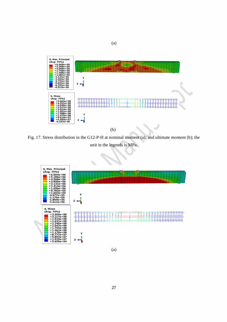
Fig. 17. Stress distribution in the G12-P-H at nominal moment (a); and ultimate moment (b); the
unit in the legends is MPa.
(a)

28
(b)
Fig. 18. Stress distribution in the G-12W-H at nominal moment (a); and ultimate moment (b);
the unit in the legends is MPa.
4.4. Stress distribution in the grout component
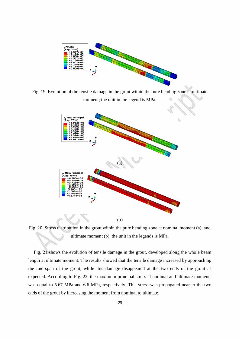
The evolution of tensile damage in the grout within the pure bending zone at ultimate moment
is shown in Fig. 19. The approximate location of generated cracks in the grout was near to the
mid-span. In addition, the maximum tensile stress in the grout was found to be 5.95 MPa and
6.56 MPa at nominal and ultimate moments as shown in Fig. 20. This stress was first generated
in the mid-span of grout at nominal moment, and then it was propagated along the whole grout
length by increasing the load. Therefore, it can be stated that the grout component effectively
participated in carrying the nominal and ultimate moments and transferring the maximum tensile
stress to the FRP bars.
29
Fig. 19. Evolution of the tensile damage in the grout within the pure bending zone at ultimate
moment; the unit in the legend is MPa.
(a)
(b)
Fig. 20. Stress distribution in the grout within the pure bending zone at nominal moment (a); and
ultimate moment (b); the unit in the legends is MPa.
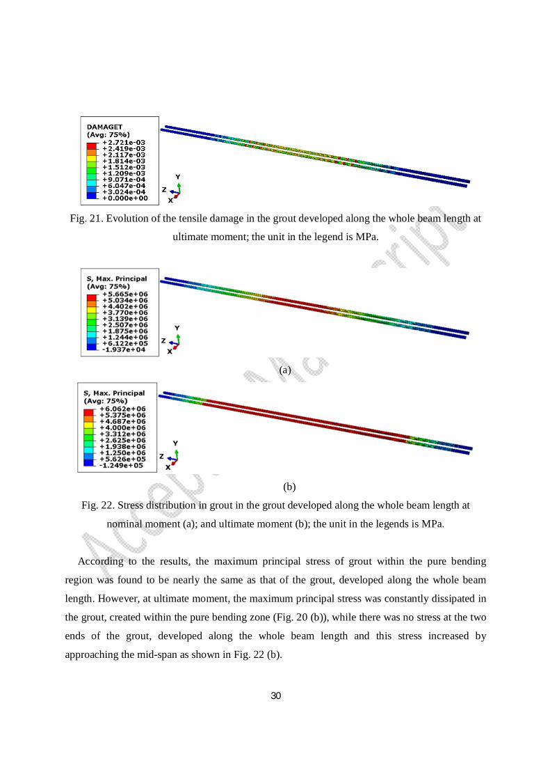
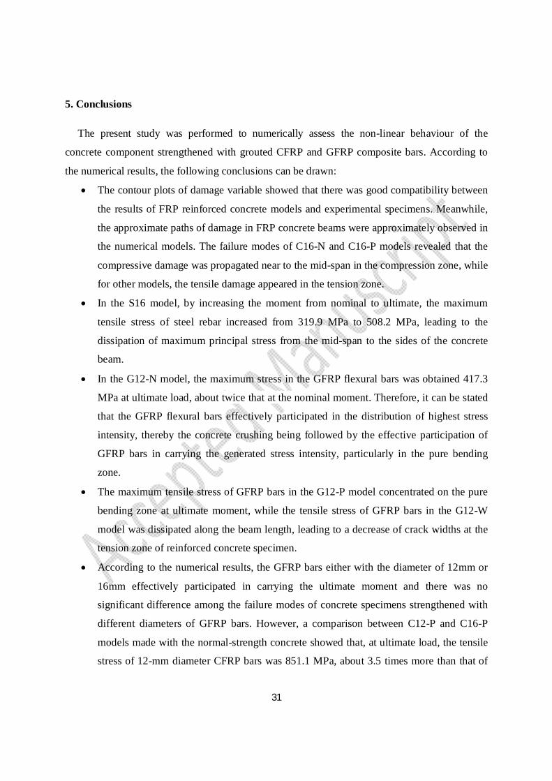
Fig. 21 shows the evolution of tensile damage in the grout, developed along the whole beam
length at ultimate moment. The results showed that the tensile damage increased by approaching
the mid-span of the grout, while this damage disappeared at the two ends of the grout as
expected. According to Fig. 22, the maximum principal stress at nominal and ultimate moments
was equal to 5.67 MPa and 6.6 MPa, respectively. This stress was propagated near to the two
ends of the grout by increasing the moment from nominal to ultimate.
30
Fig. 21. Evolution of the tensile damage in the grout developed along the whole beam length at
ultimate moment; the unit in the legend is MPa.
(a)
(b)
Fig. 22. Stress distribution in grout in the grout developed along the whole beam length at
nominal moment (a); and ultimate moment (b); the unit in the legends is MPa.
According to the results, the maximum principal stress of grout within the pure bending
region was found to be nearly the same as that of the grout, developed along the whole beam
length. However, at ultimate moment, the maximum principal stress was constantly dissipated in
the grout, created within the pure bending zone (Fig. 20 (b)), while there was no stress at the two
ends of the grout, developed along the whole beam length and this stress increased by
approaching the mid-span as shown in Fig. 22 (b).
31
5. Conclusions
The present study was performed to numerically assess the non-linear behaviour of the
concrete component strengthened with grouted CFRP and GFRP composite bars. According to
the numerical results, the following conclusions can be drawn:
The contour plots of damage variable showed that there was good compatibility between
the results of FRP reinforced concrete models and experimental specimens. Meanwhile,
the approximate paths of damage in FRP concrete beams were approximately observed in
the numerical models. The failure modes of C16-N and C16-P models revealed that the
compressive damage was propagated near to the mid-span in the compression zone, while
for other models, the tensile damage appeared in the tension zone.
In the S16 model, by increasing the moment from nominal to ultimate, the maximum
tensile stress of steel rebar increased from 319.9 MPa to 508.2 MPa, leading to the
dissipation of maximum principal stress from the mid-span to the sides of the concrete
beam.
In the G12-N model, the maximum stress in the GFRP flexural bars was obtained 417.3
MPa at ultimate load, about twice that at the nominal moment. Therefore, it can be stated
that the GFRP flexural bars effectively participated in the distribution of highest stress
intensity, thereby the concrete crushing being followed by the effective participation of
GFRP bars in carrying the generated stress intensity, particularly in the pure bending
zone.
The maximum tensile stress of GFRP bars in the G12-P model concentrated on the pure
bending zone at ultimate moment, while the tensile stress of GFRP bars in the G12-W
model was dissipated along the beam length, leading to a decrease of crack widths at the
tension zone of reinforced concrete specimen.
According to the numerical results, the GFRP bars either with the diameter of 12mm or
16mm effectively participated in carrying the ultimate moment and there was no
significant difference among the failure modes of concrete specimens strengthened with
different diameters of GFRP bars. However, a comparison between C12-P and C16-P
models made with the normal-strength concrete showed that, at ultimate load, the tensile
stress of 12-mm diameter CFRP bars was 851.1 MPa, about 3.5 times more than that of
32
the 16-mm diameter CFRP bars. Therefore, the failure modes of C12-P and C16-P
models were different, and it seems that the 12-mm diameter CFRP flexural bars
effectively participated with the normal-strength concrete in carrying the ultimate
moment, while the 16-mm diameter CFRP flexural bars, embedded in the normal-
strength concrete, moderately participated with the normal-strength concrete beam in
which the concrete crushed by reaching the ultimate compressive strain of concrete in the
compression zone without the rupture of the 16-mm diameter CFRP bars in the pure
bending zone.
The ultimate moment and mid-span deflection of high-strength concrete models strengthened
with the GFRP bars were respectively on average about 26.1% and 14.2% more than
those of the normal-strength concrete models strengthened with GFRP bars.
The GFRP bars, surrounded by the grout, propagated the maximum principal stress in the
high-strength concrete models at nominal and ultimate moments, but not as much as that
in the normal-strength concrete beams.
The approximate locations of tensile damage in the grouts, created either within the pure
bending zone or along the whole beam length, were appeared to be near to the mid-span.
Meanwhile, there was no significant difference between the maximum principal stress of
these two types of grouts, and it was in the range of 5.67-6.56 MPa.
The distribution of maximum principal stress in the grout embedded in the pure bending
region of the concrete component was found to be nearly constant, and it completely
participated in carrying the ultimate load and transferring the maximum tensile stress to
the FRP composite bars. However, there was no stress at the two ends of the grout,
developed along the whole beam length and this stress increased by approaching the mid-
span.
Acknowledgement
The authors gratefully acknowledge the Abadgaran Negin Jonoobshargh Company (A.N.J.
Co.) for their support.
References
1. I. Khan, R. François, A. Castel, Structural performance of a 26-year-old corroded
33
reinforced concrete beam, European Journal of Environmental and Civil Engineering, 16
(3–4) (2012) 440–449.
2. G. Schmitt, Global needs for knowledge dissemination, research, and development in
materials deterioration and corrosion control, World Corrosion Organization, New York,
May 2009.
3. M.H. Khaneghahi, E.P. Najafabadi, P. Shoaei, A.V. Oskouei, Effect of intumescent paint
coating on mechanical properties of FRP bars at elevated temperature, Polymer Testing, 71
(2018) 72–86.
4. S.Y. Moghadam, R. Madandoust, M.M. Ranjbar, M. Kazemi, Analytical study on the
behavior of corrosion damaged reinforced concrete beams strengthen with FRP, Romanian
Journal of Materials, 47 (2017) 514 – 521.
5. S.S.R. Koloor, M.R. Khosravani, R.I.R. Hamzah, M.N. Tamin, Fe model-based
construction and progressive damage processes of FRP composite laminates with different
manufacturing processes, International Journal of Mechanical Sciences, 141 (2018) 223–
235.
6. N.K. Parambli, S. Gururaja, Bridging micro-to-macro scale damage in UD-FRP laminates
under tensile loading, International Journal of Mechanical Sciences, 157–158, (2019) 184-
197.
7. J. Yang, J.Q. Ye, An improved closed-form solution to interfacial stresses in plated beams
using a two-stage approach, International Journal of Mechanical Sciences, 52(1) (2010) 13-
30.
8. M. Ju, Y. Park, C. Park, Cracking control comparison in the specifications of serviceability
in cracking for FRP reinforced concrete beams, Composite Structures, 182 (2017) 674-684.
9. M.H. Khaneghahi, E.P. Najafabadi, P. Shoaei, A.V. Oskouei, Effect of intumescent paint
coating on mechanical properties of FRP bars at elevated temperature, Polymer Testing, 71
(2018) 72–86.
10. F. Bencardino, A. Condello, L. Ombres, Numerical and analytical modeling of concrete
beams with steel, FRP and hybrid FRP-steel reinforcements, Composite Structures, 140
(2016) 53–65.
11. M. Jarrah, E.P. Najafabadi, M.H. Khaneghahi, A.V. Oskouei, The effect of elevated
temperatures on the tensile performance of GFRP and CFRP sheets, Construction and
34
Building Materials, 190 (2018) 38-52.
12. S.A.A. Jabbar, S.B.H. Farid, Replacement of steel rebars by GFRP rebars in the concrete
structures, Karbala International Journal of Modern Science, 4(2) (2018) 216–227.
13. A.M.M. Khorasani, M.R. Esfahani, J. Sabzi, The effect of transverse and flexural
reinforcement on deflection and cracking of GFRP bar reinforced concrete beams,
Composites Part B: Engineering, 161 (2019), 530-546.
14. A.M.M. Khorasani, M.R. Esfahani, Effect of concrete strength, arrangement/ratio of
reinforcement on flexural behavior and cracking of concrete beams reinforced with GFRP
bars, Journal of Structural and Construction Engineering (In Persian), (2018) 1-19.
15. A.F. Ashour, Flexural and shear capacities of concrete beams reinforced with GFRP bars,
Construction and Building Materials, 20 (2006) 1005-1015.
16. C.E. Ospina, C.E. Bakis, Indirect flexural crack control of concrete beams and one-way
slabs reinforced with FRP bars, Proceedings for FRPRCS-8, 2007 University of Patras,
Patras, Greece.
17. E.P. Najafabadi, A.V. Oskouei, M.H. Khaneghahi, P. Shoaei, T. Ozbakkaloglu, The tensile
performance of FRP bars embedded in concrete under elevated temperatures, Construction
and Building Materials, 211 (2019) 1138-1152.
18. K. Brozda, J. Selejdak, P. Kotes, Analysis of properties of the FRP rebar to concrete
structures, Applied Engineering Letters, 2(1) (2017) 6-10.
19. R. El-Hacha, M. Gaafar, Flexural strengthening of reinforced concrete beams using
prestressed, near-surface-mounted CFRP bars, PCI Journal, 56(4) (2011) 134–151.
20. M.M. Rafi, A. Nadjai, F. Ali, D. Talamona, Aspects of behaviour of CFRP reinforced
concrete beams in bending, Construction and Building Materials, 22 (2008) 277–285.
21. S.A.A. Mustafa, H.A. Hassan, Behavior of concrete beams reinforced with hybrid steel and
FRP composites, Housing and Building National Research Center, 14 (2018) 300-308.
22. L. Zhang, Y. Sun, W. Xiong, Experimental study on the flexural deflections of concrete
beam reinforced with Basalt FRP bars, Materials & Structures, 48(10) (2015) 3279-3293.
23. M.A. Adam, M. Said, A.A. Mahmoud, A.S. Shanour, Analytical and experimental flexural
behavior of concrete beams reinforced with glass fiber reinforced polymers bars.
Construction and Building Materials, 84 (2015) 354-366.
24. R. Okelo, R.L. Yuan, Bond strength of fiber reinforced polymer rebars in normal strength
35
concrete. Journal of Composites for Construction, 9(3) (2005) 203-213.
25. J.-Y. Lee, T.-Y. Kim, T.-J. Kim, C.K. Yi, J.-S. Park, Y.C. You, J.-H. Park, Interfacial bond
strength of glass fiber reinforced polymer bars in high-strength concrete. Composites Part
B: Engineering, 39(2) (2008) 258-270.
26. H.-L. Dong, W. Zhou, Z. Wang, Flexural performance of concrete beams reinforced with
FRP bars grouted in corrugated sleeves, Composite Structures, 215 (2019) 49-59.
27. D. Jahed Armaghani, M. Hasanipanah, H. Bakhshandeh Amnieh, D. Tien Bui, P. Mehrabi,
M. Khorami, Development of a novel hybrid intelligent model for solving engineering
problems using GS-GMDH algorithm. Engineering with Computers, (2019) 1-13.
28. B.A. Sarycheva , A.V. Gorbunova , A.V. Antonova , S.V. Yashchukb , I.G. Rodionovab ,
E.S. Fominb, Production of rolled sheet from high-strength steel with ultralow carbon
content, Steel in Translation, 42 (2) (2012) 191-195.
29. E. Hognestad, A study on combined bending and axial load in reinforced concrete
members, Univ. of Illinois at Urbana-Champaign, IL, 1951, pp. 43–46.Bulletin Series No.
399.
30. R. Madandoust, Z.F.Z. Bazkiyaei, M. Kazemi, Factor influencing point load tests on
concrete, Asian Journal of Civil Engineering, 19(8) (2018) 937–947.
31. D. Hibbitt, B. Karlsson, P. Sorensen, ABAQUS Standard User’s Manual, Version (6.11-3),
(2011).
32. J. Lee, G.L. Fenves, Plastic-damage model for cyclic loading of concrete structures,
Journal of Engineering Mechanics, 124 (8) (1998) 892–900.
33. R. Madandoust, M. Kazemi, Numerical analysis of break-off test method on concrete,
Construction and Building Materials, 151 (2017) 487–493.
34. R. Madandoust, M. Kazemi, S.Y. Moghadam, Analytical study on tensile strength of
concrete, Romanian Journal of Materials, 47(2) (2017) 204–209.
35. M. Szczecina, A. Winnicki, Calibration of the CDP model parameters in Abaqus, World
Congress on Advances in Structural Engineering and Mechanics, Incheon, Korea, (2015).
36. D.C. Drucker, W. Prager, Soil mechanics and plastic analysis or limit design, Quarterly of
Applied Mathematics, 10 (1952) 157-165.
37. P. Kmiecik, M. Kaminski, Modeling of reinforced concrete structures and composite
structures with concrete strength degradation taken into consideration, Archives of Civil

36
and Mechanical Engineering, 11(3) (2011) 623-636.
38. M. Jarrah, H. Khezrzadeh, M. Mofid, K. Jafari, Experimental and numerical evaluation of
pistonmetallic damper (PMD), Journal of Constructional Steel Research 154 (2019) 99–
109.
39. P. Zhang, X. Hu, T.Q. Bui, W. Yao, Phase field modeling of fracture in fiber reinforced
composite laminate, International Journal of Mechanical Sciences, 161-162 (2019).
40. P. Geng, G. Qin, J. Zhou, Z. Zou, Finite element models of friction behaviour in linear
friction welding of a Ni-based superalloy, International Journal of Mechanical Sciences,
152 (2019) 420-431.
41. M. Mohammadi, M.A. Kafi, A. Kheyroddina , H.R. Ronagh, Experimental and numerical
investigation of an innovative buckling-restrained fuse under cyclic loading, Structures, 22
(2019) 186-199.
42. M. Kazemi, MA Kafi, M Hajforoush, A Kheyroddin, Cyclic behaviour of steel ring filled
with compressive plastic or concrete, installed in the concentric bracing system, Asian
Journal of Civil Engineering, (2019) 1-11.
43. W. Zhang, G. Subhash, An elastic-plastic-cracking model for finite element analysis of
indentation cracking in brittle materials, International Journal of Solids and Structures,
2001, 38(34-35), 5893-5913.
44. J. Ruzicka, M. Spaniel, A. Prantl, J. Dzugan, J. Kuzelka, M. Moravec, Identification of
ductile damage parameters in the Abaqus, Bulletin of Applied Mechanics, 8 (2012) 89-92.
45. S. Jahandari, M. Saberian, Z. Tao, S. Faridfazel Mojtahedi, J. Li, M. Ghasemi, S.S.
Rezvani, W. Li, Effects of saturation degrees, freezing thawing, and curing on geotechnical
properties of lime and lime-cement concretes, Cold Regions Science and Technology, 160
(2019) 242–251.
46. H. AzariJafari, A. Tajadini, M. Rahimi, J. Berenjian, Reducing variations in the test results of
self-consolidating lightweight concrete by incorporating pozzolanic materials, Construction
and Building Materials, 166 (2018) 889–897.
47. M. Saberian, S. Jahandari, J. Li, F. Zivari, Effect of curing, capillary action, and
groundwater level increment on geotechnical properties of lime concrete: Experimental
and prediction studies, Journal of Rock Mechanics and Geotechnical Engineering, 9(4)
(2017a) 638–647.
37
48. M. Kazemi, R. Madandoust, J. de Brito, Compressive strength assessment of recycled
aggregate concrete using Schmidt rebound hammer and core testing, Construction and
Building Materials, 224 (2019) 630–638.
49. S. Jahandari, M.M. Toufigh, J. Li, M. Saberian, Laboratory study of the effect of degrees
of saturation on lime concrete resistance due to the groundwater level increment,
Geotechnical and Geological Engineering, 36(1) (2017a) 413–424.
50. R. Madandoust, M. Kazemi, P. Khkapour Talebi, J. de Brito, Effect of the curing type on
the mechanical properties of lightweight concrete with polypropylene and steel fibres,
Construction and Building Materials, 223 (2019) 1038-1052.
51. S. Jahandari, Laboratory study of moisture and capillarity impact on lime concrete resistance
due to the increase of ground water level. M.Sc. thesis, Faculty of Civil and Surveying
Engineering, Department of Geotechnical Engineering, Graduate University of Advanced
Technology, Kerman, Iran, 2015.
52. H. AzariJafari, M.J.T. Amiri, A. Ashrafian, H. Rasekh, M.J. Barforooshi, J. Berenjian,
Ternary blended cement: an eco-friendly alternative to improve resistivity of high-
performance self-consolidating concrete against elevated temperature, Journal of Cleaner
Production, 223 (2019) 575–586.
53. A. Sadrmomtazi, B. Tahmouresi, A. Saradar, Effects of silica fume on mechanical strength
and microstructure of basalt fiber reinforced cementitious composites (BFRCC),
Construction and Building Materials, 162 (2018) 321–333.
54. A. El-Nemr, E.A. Ahmed, B. Benmokrane, Flexural behavior and serviceability of normal-
and high-strength concrete beams reinforced with glass fiber-reinforced polymer bars, ACI
Structural Journal, 110(6) (2013) 1077-1088.
View publication statsView publication stats