Non-Dispersive Infrared (NDIR) Transmitter · 2.3 Display And User Interface ... detector for...
41
RAEGuard S EC Toxic Gas and Oxygen Transmitter P/N 033-4117-E00 Rev A August 2009 User’s Guide RAEGuard S LEL Combustible Gas Transmitter RAEGuard S IR Non-Dispersive Infrared (NDIR) Transmitter
Transcript of Non-Dispersive Infrared (NDIR) Transmitter · 2.3 Display And User Interface ... detector for...
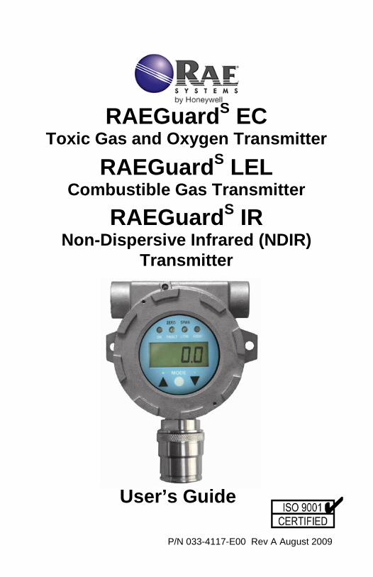
RAEGuardS EC Toxic Gas and Oxygen Transmitter
P/N 033-4117-E00 Rev A August 2009
User’s Guide
RAEGuardS LEL Combustible Gas Transmitter
RAEGuardS IR
Non-Dispersive Infrared (NDIR) Transmitter

RAEGuardS EC / LEL / IR User’s Guide
1
- READ BEFORE OPERATING - This manual must be carefully read by all individuals who have or will have the responsibility of using, maintaining, or servicing this product. The product will perform as designed only if it is used, maintained, and serviced in accordance with the manufacturer’s instructions. The user should understand how to set the correct parameters and interpret the obtained results.
CAUTION! To reduce the risk of electric shock, turn the power off before removing the instrument cover. Disconnect the power before removing the sensor module for service. Never operate the instrument when the cover is removed. Remove instrument cover and sensor module only in an area known to be non-hazardous.
WARNING!
The calibration of all newly purchased RAE Systems instruments should be tested by exposing the sensors to known concentration calibration gas before the instrument is used or put into service. For maximum safety, the accuracy of the RAEGuardS should be checked by exposing the sensor(s) to known concentration calibration gas every three (3) months.

RAEGuardS EC / LEL / IR User’s Guide
2
Contents 1. General Information ......................................................................... 3 1.1 General Specifications ............................................................... 6 RAEGuardS EC Specifications ................................................. 6 RAEGuardS IR Specifications ................................................... 7 RAEGuardS LEL Specifications ................................................ 9 2. Operation ....................................................................................... 10 2.1 Physical Description ................................................................ 11 2.2 Installation and Access Instructions ........................................ 11 Mounting .................................................................................. 12 Instrument Assembly Removal ................................................ 13 Electrical Wiring ....................................................................... 14 Instrument Assembly Installation ............................................. 15 Earth Grounding Instructions ................................................... 16 2.3 Display And User Interface ...................................................... 18 User Interface .......................................................................... 18 Magnet Key ............................................................................. 18 Using The Magnet Key ............................................................ 19 System Initialization ................................................................. 19 Reading Display ...................................................................... 20 Alarm Contacts ........................................................................ 20 2.4 Calibration ............................................................................... 21 Zero Calibration ....................................................................... 22 Span Calibration ...................................................................... 23 2.5 Advanced Menu (EC & LEL) ................................................... 25 2.6 Advanced Menu (IR) ................................................................ 31 2.7 Restoring Default Values (EC & LEL) ................................... 31 3. Theory of Operation ....................................................................... 33 4. Maintenance .................................................................................. 35 5. Troubleshooting ............................................................................. 35 Table A: EC Sensor configuration ................................................ 37 6. ModBus/RS-485 Information ......................................................... 38

RAEGuardS EC / LEL / IR User’s Guide
3
1. General Information RAEGuardS EC The RAEGuardS EC is a fixed electrochemical detector for oxygen and toxic gas (CO, H2S, SO2, NO, NO2, Cl2, O2, ClO2, NH3, PH3, HCN and ETO). It operates with voltages from 9 to 36 VDC and provides an analog (4 to 20mA) output signal and digital (RS-485, ModBus) output signal within the corresponding ranges of gas detection. The RAEGuardS EC uses an interchangeable electrochemical smart sensor, which can be pre-calibrated independently offline. Housed in an explosion-proof enclosure, the RAEGuardS EC is equipped with a local digital display of the gas concentration and unit of measurement, status LEDs, and function keys for performing calibration. RAEGuardS IR The RAEGuardS IR is fixed non-dispersive infrared (NDIR) detector for hydrocarbon combustible gases, carbon dioxide, and other gases, It operates with voltages from 9 to 36 VDC and provides an analog (4 to 20mA) output signal and digital (RS-485, ModBus) output signal within the corresponding ranges of gas detection of 0 to 100% LEL or 0 to 50,000 ppm CO2. The RAEGuardS IR uses a smart NDIR sensor, which can be pre-calibrated independently offline. Housed in an explosion-proof stainless steel enclosure, the RAEGuardS IR is equipped with a local digital display of the gas concentration, status LEDs, and function keys for performing calibration. RAEGuardS LEL The RAEGuardS LEL is a fixed, highly poison-resistant catalytic bead lower explosion limit (LEL) sensor for combustible gases detection. It operates with voltages from 9 to 36 VDC and provides an analog (4 to 20mA) output signal and digital (RS-485, ModBus) output signal within the corresponding range of 0 to 100% LEL. The RAEGuardS LEL uses a smart LEL sensor, which can be pre-calibrated independently offline. Housed in an explosion-proof stainless-steel enclosure, the RAEGuardS LEL is equipped with a local digital display of the gas concentration, status LEDs, and function keys for performing calibration.

RAEGuardS EC / LEL / IR User’s Guide
4
Key features:
• Interchangeable smart electrochemical sensor that can be calibrated offline
• 4 to 20mA analog output signal. • RS-485 digital communication in ModBus Protocol • Explosion-proof stainless-steel enclosure for hazardous
environment applications • Magnetic-key interface eliminates the need to open the explosion-
proof housing when adjusting parameters. • LCD and status/error LEDs • LED alarms when High or Low alarm point is reached • Operation at 9 to 36 VDC • Two dry contacts (<30V, 2A) normally open (or normally closed),
one for High and Low alarm, another for Fault alarm
Applications:
• Waste water treatment plants • Petroleum and natural gas fields • Marine and offshore oil wells • Refineries and petrochemical plants • Solvent recovery systems • Chemical plants • Industrial safety • Sewers and pipelines • Pulp & paper plants • Heavy industry • Power plants • Steel mills

RAEGuardS EC / LEL / IR User’s Guide
5
Hazardous Location Classification:
ATEX: II 2G Ex d IIC T6 -40° C < Tamb < +60° C Complies with EN60079-0 :2004, EN60079-1 :2004
Example Of Name Plate On RAEGuardS Models:
Notes:
Sensor Name is replaced by the actual sensor name. FGM-1XXXS is replaced by model number. * < 4 ** Optional

RAEGuardS EC / LEL / IR User’s Guide
6
1.1 General Specifications RAEGuardS EC Specifications
Size 7.4" L x 5.9" W x 4.3" H
188mm x 150mm x 109mm
Weight 7.7 lbs 3.5 kg
Detector Off-line pre-calibrated interchangeable smart electrochemical sensor
Calibration 2-point calibration
Certification ATEX: II 2G Ex d IIC T6 -40° C < Tamb < +60° C Complies with EN60079-0 :2004, EN60079-1 :2004
IP Rating IP-65 Power 9 to 36VDC, max 40mA at 24V or 1W
Output 4-20mA RS-485, baud-rate 4.8, 9.6 or 19.2kb/sec
Sampling Internal diffusion
Display 7-segment, 4-digit LCD and 4 color-coded alarm LEDs
User Interface Magnetically accessed keys for non-intrusive calibration and adjustment
Temperature -40° C to 60° C Humidity 0% to 95% relatively humidity (non-condensing) Pressure 0.9 to 1.1 Atm
Dry contact Max 30V, 2A
Dry Contacts 30V, 2A, normally open (or normally closed), one for High and Low alarm, another for Fault alarm
Terminal AWG 24-12
Mounting 2 holes, 5.25" (133mm) from center to center
RAEGuardS EC / LEL / IR User’s Guide
7
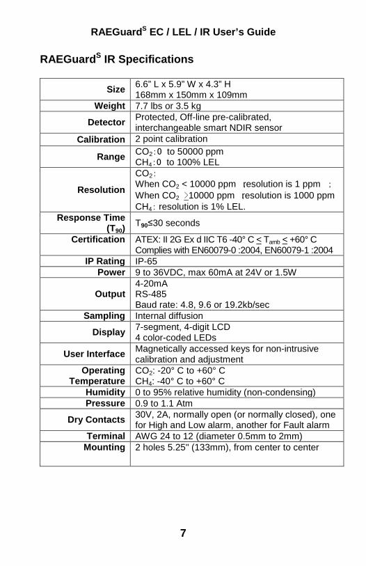
RAEGuardS IR Specifications
Size 6.6” L x 5.9” W x 4.3” H 168mm x 150mm x 109mm
Weight 7.7 lbs or 3.5 kg
Detector Protected, Off-line pre-calibrated, interchangeable smart NDIR sensor
Calibration 2 point calibration
Range CO2:0 to 50000 ppm CH4:0 to 100% LEL
Resolution
CO2: When CO2 < 10000 ppm ,resolution is 1 ppm ; When CO2 >10000 ppm ,resolution is 1000 ppm CH4: resolution is 1% LEL.
Response Time (T90)
T90≤30 seconds
Certification ATEX: II 2G Ex d IIC T6 -40° C < Tamb < +60° C Complies with EN60079-0 :2004, EN60079-1 :2004
IP Rating IP-65 Power 9 to 36VDC, max 60mA at 24V or 1.5W
Output 4-20mA RS-485 Baud rate: 4.8, 9.6 or 19.2kb/sec
Sampling Internal diffusion
Display 7-segment, 4-digit LCD 4 color-coded LEDs
User Interface Magnetically accessed keys for non-intrusive calibration and adjustment
Operating Temperature
CO2: -20° C to +60° C CH4: -40° C to +60° C
Humidity 0 to 95% relative humidity (non-condensing) Pressure 0.9 to 1.1 Atm
Dry Contacts 30V, 2A, normally open (or normally closed), one for High and Low alarm, another for Fault alarm
Terminal AWG 24 to 12 (diameter 0.5mm to 2mm) Mounting 2 holes 5.25" (133mm), from center to center
RAEGuardS EC / LEL / IR User’s Guide
8
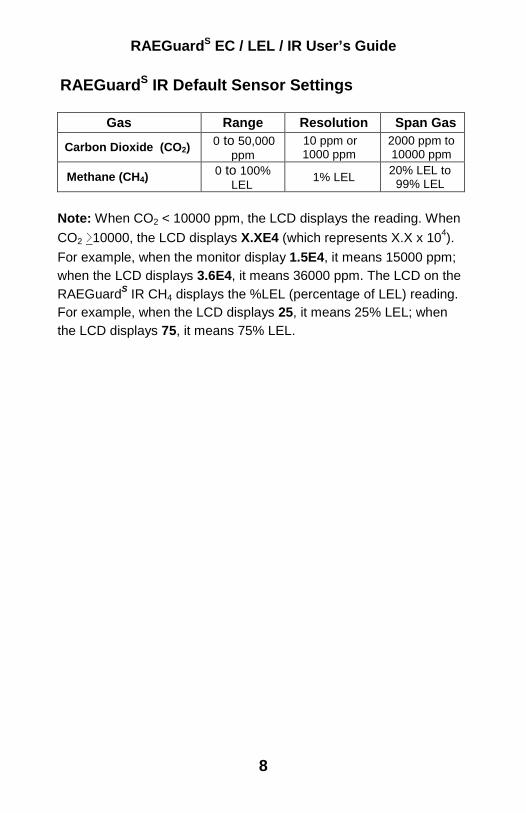
RAEGuardS IR Default Sensor Settings
Gas Range Resolution Span Gas
Carbon Dioxide (CO2) 0 to 50,000 ppm
10 ppm or 1000 ppm
2000 ppm to 10000 ppm
Methane (CH4) 0 to 100% LEL 1% LEL 20% LEL to
99% LEL Note: When CO2 < 10000 ppm, the LCD displays the reading. When CO2 >10000, the LCD displays X.XE4 (which represents X.X x 104). For example, when the monitor display 1.5E4, it means 15000 ppm; when the LCD displays 3.6E4, it means 36000 ppm. The LCD on the RAEGuardS IR CH4 displays the %LEL (percentage of LEL) reading. For example, when the LCD displays 25, it means 25% LEL; when the LCD displays 75, it means 75% LEL.

RAEGuardS EC / LEL / IR User’s Guide
9
RAEGuardS LEL Specifications Size 6.6” L x 5.9” W x 4.3” H
168mm x 150mm x 109mm Weight 7.7 lbs or 3.5 kg
Detector Protected, Off-line pre-calibrated, interchangeable catalytic bead smart LEL sensor
Calibration 2 point calibration Range 0 to 100% LEL
Resolution 1% LEL Response Time
(T90) <15 seconds to 90% of reading to 50% LEL methane
Certification ATEX: II 2G Ex d IIC T6 -40° C < Tamb < +60° C Complies with EN60079-0 :2004, EN60079-1 :2004
IP Rating IP-65 Power 9 to 36VDC, max 60mA at 24V or 1.5W
Output 4-20mA RS-485, Baud-rate 4.8, 9.6 or 19.2kb/sec
Sampling Internal diffusion
Display 7-segment, 4-digit LCD 4 color-coded LEDs
User Interface Magnetically accessed keys for non-intrusive calibration and adjustment
Operating Temperature
-40° C to +60° C
Humidity 0 to 95% relative humidity (non-condensing) Pressure 0.9 to 1.1 Atm
Dry Contacts 30V, 2A, normally open (or normally closed), one for High and Low alarm, another for Fault alarm
Terminal AWG 24 to AWG 12 (diameter 0.5mm to 2mm)
Mounting 2 holes, 5.25" (133mm) from center to center
RAEGuardS EC / LEL / IR User’s Guide
10
2. Operation The calibration of all newly purchased RAE Systems instruments should be tested by exposing the sensor(s) to a known concentration calibration gas before the instrument is used or put into service. For maximum safety, the accuracy of the RAEGuardS EC should be checked by exposing the sensor(s) to a known concentration calibration gas, after a period of time. Calibration should be verified daily during the period of initial use in the intended atmosphere to ensure nothing is poisoning the sensor(s). The period of initial use must be of sufficient duration to ensure that the sensors are exposed to all conditions that might have an adverse effect on the sensors. Verify the calibration with a known concentration test gas before use. This “bump” test is very simple. Recalibrate the unit if readings are off. Prior to factory shipment, the RAEGuardS EC is calibrated and tested using span gas. However, the user should calibrate the instrument before the first use. After the unit is installed, run for 24 hours, and calibrated, it is ready for immediate operation. Calibration setting values for EC sensors are shown as Table A (on page 32). Kit Accessories include: Calibration Adapter, RAEGuard Magnet Key, and User’s Guide.

RAEGuardS EC / LEL / IR User’s Guide
11
2.1 Physical Description The design of RAEGuardS allows it to be easily mounted and interfaced to a fixed-point gas monitoring system. The RAEGuardS EC and LEL are housed in a 7.4" L x 5.9" W x 4.3" H (188mm x 150mm x 109mm) case with two holes 5.25" (133 mm) from center to center. The RAEGuardS IR’s dimensions vary slightly because of the sensor size: 6.6" L x 5.9" W x 4.3" H (168mm x 150mm x 109mm).
Ø 4 1/2" (114.30)
4.29" (109.0)
1.04" (26.4)
3/4" -14NPT
5.0" (127)
5.24" (133)
Ø.315"(8)
3/4" -14NPT
7.40" (188)
4.92" (125)
Note: This dimension is 6.6" (168mm) on the RAEGuardS IR and LEL.
RAEGuardS EC / LEL / IR User’s Guide
12
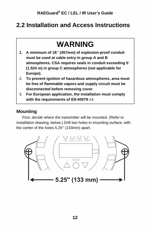
2.2 Installation and Access Instructions
Mounting First, decide where the transmitter will be mounted. (Refer to installation drawing, below.) Drill two holes in mounting surface, with the center of the holes 5.25" (133mm) apart.
WARNING 1. A minimum of 18" (457mm) of explosion-proof conduit
must be used at cable entry in group A and B atmospheres. CSA requires seals in conduit exceeding 5' (1.524 m) in group C atmospheres (not applicable for Europe).
2. To prevent ignition of hazardous atmospheres, area must be free of flammable vapors and supply circuit must be disconnected before removing cover.
3. For European application, the installation must comply with the requirements of EN 60079-14.
RAEGuardS EC / LEL / IR User’s Guide
13
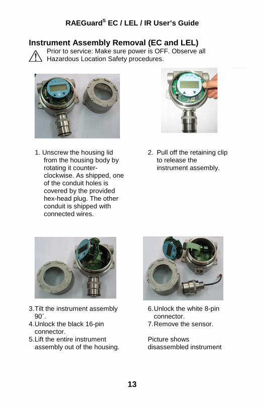
Instrument Assembly Removal (EC and LEL) Prior to service: Make sure power is OFF. Observe all Hazardous Location Safety procedures.
1. Unscrew the housing lid from the housing body by rotating it counter-clockwise. As shipped, one of the conduit holes is covered by the provided hex-head plug. The other conduit is shipped with connected wires.
3. Tilt the instrument assembly 90˚.
4. Unlock the black 16-pin connector.
5. Lift the entire instrument assembly out of the housing.
6. Unlock the white 8-pin connector.
7. Remove the sensor. Picture shows disassembled instrument
2. Pull off the retaining clip to release the instrument assembly.

RAEGuardS EC / LEL / IR User’s Guide
14
Instrument Assembly Removal (IR) Prior to service: Make sure power is OFF. Observe all Hazardous Location Safety procedures.
1. Unscrew the housing lid from the housing body by rotating it counter-clockwise. As shipped, one of the conduit holes is covered by the provided hex-head plug. The other conduit is shipped with connected wires.
6. Tilt the instrument assembly 90˚.
7. Unlock the 20-pin connector. 8. Lift the entire instrument
assembly out of the housing.
6. Unlock the 12-pin connector.
7. Remove the sensor. Picture shows disassembled instrument
2. Pull off the retaining clip to release the instrument assembly.

RAEGuardS EC / LEL / IR User’s Guide
15
Electrical Wiring 1. Inside the housing bottom, unplug the two green terminal block
plugs from the terminal block on the PC boards. Note: The terminal block plugs accept 12 AWG to 24 AWG wire.
2. Lace the wires through the RAEGuardS EC’s wire hole(s) and connect wires to the corresponding pin numbers of the terminal blocks: Terminal Wire Pin# Block 1 Alarm Common (COM) 1
High/Low Alarm (ALM1) 2 Fault Alarm (ALM2) 3 RS485A (485A) 4 RS485B (485B) 5
Block 2 4-20 mA Output (4-20mA) 6 Power Supply - Output Common (P-) 7 Power Supply + (9 to 36VDC) (P+) 8
Instrument Assembly Installation 1. Plug all terminal block plugs into the correct terminal block headers.
Keep the extra wires as close to the inside enclosure wall as possible. 2. Screw the sensor module to the housing and plug the 8-pin (EC) or 10-
pin (LEL model) or 12-pin (IR model) connector back into its socket. 3. Plug the 16-pin (EC or LEL model) or 20-pin (IR model) connector back
into its socket. 4. Pull off the clip to place the instrument assembly back into the housing
bottom. 5. Tightly screw the housing top to the housing bottom.
RAEGuardS EC / LEL / IR User’s Guide
16
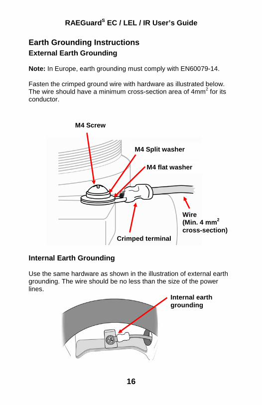
Earth Grounding Instructions External Earth Grounding Note: In Europe, earth grounding must comply with EN60079-14. Fasten the crimped ground wire with hardware as illustrated below. The wire should have a minimum cross-section area of 4mm2 for its conductor. Internal Earth Grounding Use the same hardware as shown in the illustration of external earth grounding. The wire should be no less than the size of the power lines.
M4 flat washer
M4 Split washer
M4 Screw
Wire (Min. 4 mm2 cross-section)
Crimped terminal
Internal earth grounding
RAEGuardS EC / LEL / IR User’s Guide
17
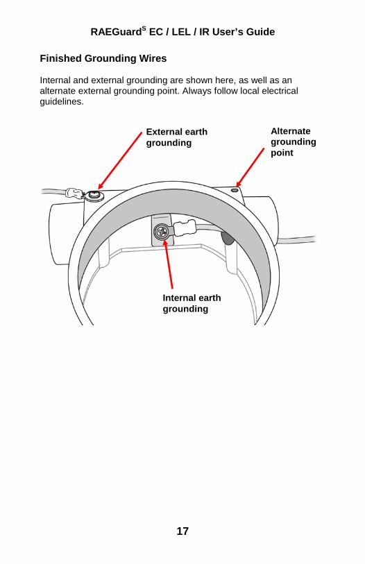
Finished Grounding Wires Internal and external grounding are shown here, as well as an alternate external grounding point. Always follow local electrical guidelines.
Alternate grounding point
Internal earth grounding
External earth grounding
RAEGuardS EC / LEL / IR User’s Guide
18
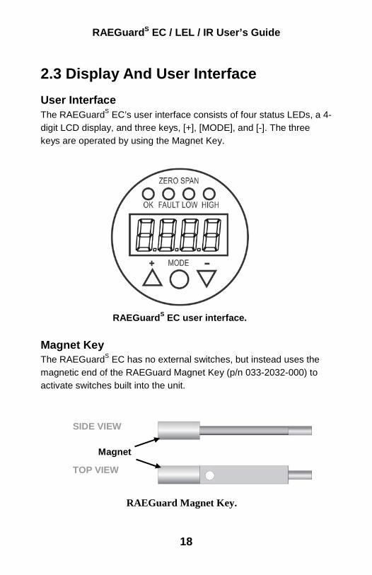
2.3 Display And User Interface User Interface The RAEGuardS EC’s user interface consists of four status LEDs, a 4-digit LCD display, and three keys, [+], [MODE], and [-]. The three keys are operated by using the Magnet Key.
RAEGuardS EC user interface.
Magnet Key The RAEGuardS EC has no external switches, but instead uses the magnetic end of the RAEGuard Magnet Key (p/n 033-2032-000) to activate switches built into the unit.
RAEGuard Magnet Key.
Magnet
SIDE VIEW TOP VIEW
RAEGuardS EC / LEL / IR User’s Guide
19
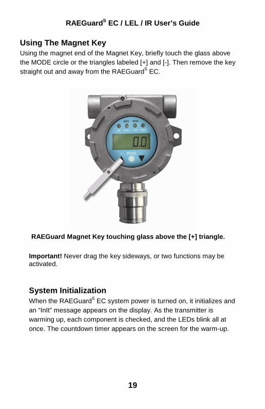
Using The Magnet Key Using the magnet end of the Magnet Key, briefly touch the glass above the MODE circle or the triangles labeled [+] and [-]. Then remove the key straight out and away from the RAEGuardS EC.
RAEGuard Magnet Key touching glass above the [+] triangle.
Important! Never drag the key sideways, or two functions may be activated.
System Initialization When the RAEGuardS EC system power is turned on, it initializes and an “InIt” message appears on the display. As the transmitter is warming up, each component is checked, and the LEDs blink all at once. The countdown timer appears on the screen for the warm-up.

RAEGuardS EC / LEL / IR User’s Guide
20
Reading Display As the transmitter enters the Reading Display, it automatically starts testing for errors and goes through a cycle of checking each alarm condition. If there are no errors or alarm conditions, the green “OK” LED is lit and the gas concentration is displayed. If there is an error, the “Fault” LED blinks and an error message blinks. Each alarm condition has a corresponding LED that blinks an amber color when the readings are outside a specified range or limit.
Alarm Contacts The alarm contacts or alarm relay can be used to drive user-supplied external alarms such as a light or buzzer. The external alarms open in normal conditions and close when an alarm occurs.
Default Alarm Relay Logic
External Alarm
LED LCD Analog Output
Exceeds Low alarm limit
ALM 1 Alarm Low reading Based on reading
Exceeds High alarm limit
ALM 1 Alarm High reading Based on reading
Over Range ALM 2 Alarm High 8888 22mA
Calibration fail ALM 2 Alarm Fault Flashing E003
2mA
Sensor drift* ALM 2 Alarm Fault Flashing E004
2mA
ADC saturated *(max)
ALM 2 Alarm Fault Flashing E005
2mA
* RAEGuardS EC and LEL only.

RAEGuardS EC / LEL / IR User’s Guide
21
2.4 Calibration
The RAEGuardS is calibrated using a two-point calibration process. First, use a “zero gas.” Then use a “span gas” containing a known concentration of a standard reference gas, to set the second point of reference. Note: The zero calibration must be performed before the span calibration.
RAEGuardS connected to gas cylinder with a calibration adapter.
Gas calibration requires a bottle of zero gas, a bottle of span gas, and a calibration adapter.
WARNING The calibration of all newly purchased RAE Systems instruments should be tested by exposing the sensor(s) to a known concentration calibration gas before the instrument is used or put into service. For maximum safety, the accuracy of the RAEGuardS should be checked by exposing the sensor to a known concentration calibration gas, after a period of time.

RAEGuardS EC / LEL / IR User’s Guide
22
Zero Calibration 1. Connect the zero gas cylinder to the metal filter gas adapter on
the RAEGuardS transmitter using the provided calibration adapter.
2. To access the Calibration menu, press [MODE] from the Reading Display. Zero calibration appears first, as indicated by the “Zero” message on the screen. Optional: To advance to span calibration, press [MODE] a second time. “Span” appears on the screen. Skip to Span Calibration instructions on the next page. Optional: To exit the Calibration menu, press [-] to return to the Reading Display.
3. Turn on the gas flow. Allow gas to flow into the sensor for 30 seconds before zero calibration. Then press [+] to start calibration. The “Zero” LED starts blinking, and the “Zero” message alternates with a countdown timer. Optional: Before the countdown reaches zero, you may press any key to interrupt zero calibration and advance to span calibration.
4. Once the countdown reaches zero, the “Zero” LED stops blinking, and the zero calibration data is saved. Note: The transmitter returns to the Reading Display after 60 seconds of idle time.
5. Turn off the zero calibration gas and remove the cylinder.

RAEGuardS EC / LEL / IR User’s Guide
23
Zero calibration automatically advances to span calibration when complete.
Span Calibration 1. Connect the span gas cylinder to the metal filter gas adapter on
the RAEGuardS transmitter using the provided calibration adapter.
RAEGuardS EC / LEL / IR User’s Guide
24
Optional: To access span calibration from the Reading Display, press [MODE]. After “Zero” appears on the screen, press [MODE] a second time to advance to span calibration. Optional: To access span calibration after zero calibration has already started, press any key to advance to span calibration. Optional: To exit the calibration menu, press [-] to return to the Reading Display. Note: It is not necessary to exit manually. After 60 seconds of idle time, the RAEGuardS automatically returns to the Reading Display.
2. Turn on the gas flow. First, let gas flow into the sensor for 30 seconds before span calibration.Then press [+] to start calibration. The “Span” LED starts blinking. The “Span” message alternates with a countdown timer. Note: Wait for the entire countdown for a complete calibration. Optional: Before the countdown reaches zero, you may press any key to interrupt span calibration and return to the Reading Display.
3. Once the countdown reaches zero, the “Span” LED stops blinking.
4. If the sensor sensitivity is unacceptable, the screen alternately flashes a “Span” and “FAIL” message until any key is pressed.
Note: If span calibration fails, it may be necessary to replace the sensor.
5. You may choose to press [-] or [MODE] to return to zero calibration and restart the entire calibration process, or press [+] to go to the Reading Display.

RAEGuardS EC / LEL / IR User’s Guide
25
6. If the sensor’s sensitivity is acceptable, the span data is calculated and saved.
7. The calibration procedure is complete. After a few seconds, the transmitter returns to the Reading Display.
8. Turn off span calibration gas and remove the cylinder.
2.5 Advanced Menu (EC & LEL) The Advanced menu on the RAEGuardS EC and LEL allows you to change the values for each reading and setup option. To access the Advanced menu from the Reading Display, first press [+], [-],and then [MODE] in sequence. Then scroll through the parameters shown below by pressing [MODE].
Once you have entered the Advanced Menu, you can edit the parameters for each item in the list.

RAEGuardS EC / LEL / IR User’s Guide
26
Note: Anytime a submenu screen is idle for more than 60 seconds, the transmitter returns to the Reading Display. Advanced Menu Display Explanation CALu Calibration Concentration Value CF Correction Factor, only for RAEGuardS LEL and IR LO Low Alarm HI High Alarm Id Client ID bAUd Baud rate. Supports 19200, 9600, or 4800 LItE Backlight Aout Analog output 4mA and 20mA adjustment tESt Test Function of LED, External Alarm, and 4-20mA
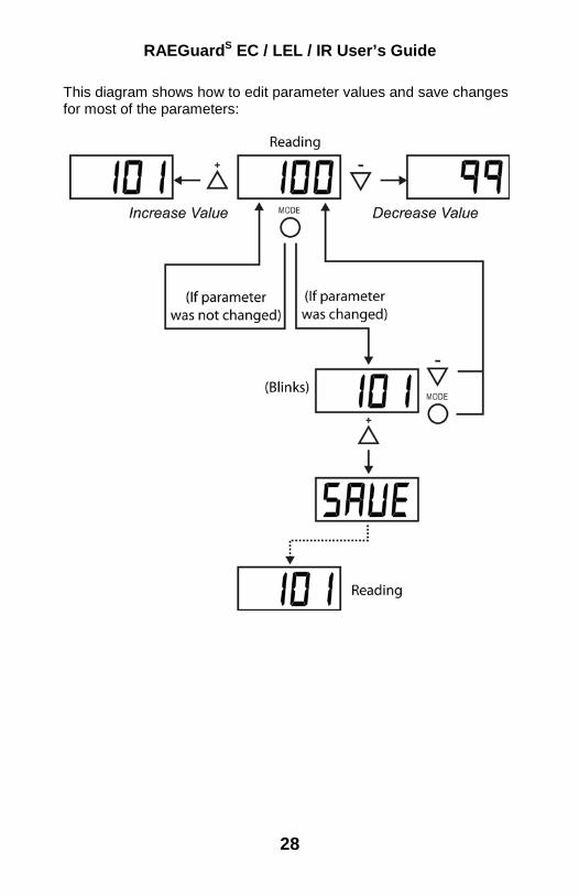
• To change a value, press [MODE] until the desired parameter appears.
• Press [+] to enter the Process Menu. • To increase a value, press [+]. • To decrease a value, press [-]. • When finished changing the value, press [MODE].
If a value has changed, the new value blinks on the LCD.
• Press [-] or [MODE] to discard changes and advance to the next submenu item.
• Press [+] to save changes. The “SAVE” message appears on the screen to confirm changes have been saved.

RAEGuardS EC / LEL / IR User’s Guide
27
After entering the Advanced Menu, step through the parameters by pressing [MODE]. To edit a parameter, press [+]. The screen shows the current reading value of the parameter. You can exit Advanced Menu at any screen by pressing [-]. In addition, Advanced Menu is automatically exited if you do not make any changes within 60 seconds.
RAEGuardS EC / LEL / IR User’s Guide
28
This diagram shows how to edit parameter values and save changes for most of the parameters:

RAEGuardS EC / LEL / IR User’s Guide
29
This diagram shows the submenu of parameters for the 4-20mA Analog Menu:
RAEGuardS EC / LEL / IR User’s Guide
30
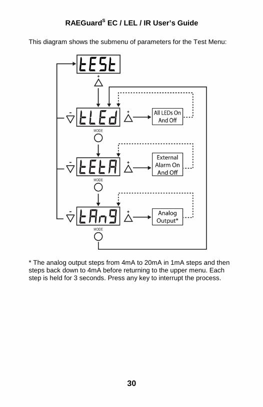
This diagram shows the submenu of parameters for the Test Menu:
* The analog output steps from 4mA to 20mA in 1mA steps and then steps back down to 4mA before returning to the upper menu. Each step is held for 3 seconds. Press any key to interrupt the process.

RAEGuardS EC / LEL / IR User’s Guide
31
2.6 Advanced Menu (IR)
The Advanced menu allows the user to change the values for each reading and setup option. To access the Advanced menu from the Reading Display, first press [+], [-],and then [MODE] in sequence. Then scroll through the parameters shown below by pressing [MODE].
Anytime a submenu screen is idle for more than 60 seconds, the transmitter will return to the Reading Display.
Advanced Menu Submenu LCD display Default Standard gas concentration
CO2: C5E3 (represents 5000 ppm)
CH4: C050 (represents 50% LEL)
CO2: C5E3 CH4: C050
Low alarm CO2: L4E3 (4000 ppm) CH4: L020 (20% LEL)
CO2: L4E3 CH4: L020
High alarm CO2: H8E3 (8000 ppm) CH4: H050 (50% LEL)
CO2: H8E3 CH4: H050
User ID IdXX Id00 Baud-rate (kBaud)
B19.2, B09.6, B04.8 (19200, 9600, and 4800)
B09.6
4mA output adjust
A04
20mA output adjust
A20

RAEGuardS EC / LEL / IR User’s Guide
32
To change a value, press [MODE] until the desired parameter appears. Then press [+] to enter the Process Menu.
• To increase a value, press [+]. • To decrease a value, press [-].
Press [MODE] when finished changing the value. If a value has changed, the new value blinks on the LCD.
• Press [-] or [MODE] to discard changes and advance to the next submenu item.
• Press [+] to save changes. The “SAVE” message appears on the screen to confirm changes have been saved.
2.7 Restoring Default Values (EC & LEL) You can reset all values in the RAEGuardS EC and LEL to factory default values. Follow this procedure: 1. Press [MODE] to Zero. 2. Press [MODE] to SPAN. 3. Press [MODE] key to show DEFT in the display. 4. Press [+]. The display flashes DEFT and awaits confimation. 5. Press [+] to Save the change. All data is cleared and the default
values are now restored.

RAEGuardS EC / LEL / IR User’s Guide
33
3. Theory of Operation The RAEGuardS EC uses electrochemical sensors. The electrons generated at the working electrode travel via the contact pins to be measured at the external circuit and are returned to the counter electrode to complete the circuit, The current of the sensor response is proportional to the related EC sensors’ gas concentration. The RAEGuardS IR is based on the patented technology of non-dispersive infrared (NDIR) for hydrocarbon, carbon dioxide and other gas detection. After sample gas diffuses into the infrared optical gas sensor, the electro-magnetic radiation cause oscillation on gas molecules. If this happens the oscillation reduces the amount of radiation, it absorbs a certain degree of radiation. The absorbance at specified wavelength is a measure of the present gas concentration.
The RAEGuardS LEL uses a highly poison-resistant catalytic bead lower explosion limit (LEL) sensor. After sample gas diffuses through the metal sinter into the combustion chamber, a pair of combustion elements inside the combustion chamber burns the combustible gas and generates an electrical signal.
The RAEGuardS is a microcontroller-based instrument. After the electrical signal is conditioned and converted to digital, the microcontroller processes the data, which displays the results locally and reconstructs the digital data into a standard 4-20 mA analog current output signal and RS-485 digital output signal.
The instrument has three magnetic sensing keys. The user may calibrate the transmitter and change the alarm level setting via the magnetic front-panel key pad.

RAEGuardS EC / LEL / IR User’s Guide
34
The instrument is powered by a DC power supply located in a safe area. The power supply on the PC board contains a switching and linear regulator that converts the main input voltage to 3.3V and 5V DC to power the entire circuit.

RAEGuardS EC / LEL / IR User’s Guide
35
4. Maintenance As a guide, it is recommended to regularly “bump test” a RAEGuardS unit with a known percentage gas.
Exploded View of RAEGuardS EC and LEL Components
Periodically examine the sensor’s opening to make sure it is not dirty or covered in dust or debris. If the sensor requires replacement, refer this unit to qualified service personnel. Use “anti sieze” lubricant on lid threads. Lid must be tightened down following removal and the set screw that prevents the lid from coming loose must also be tightened. Also check that all cable glands are tight at regular intervals.
Holder
7R EC, LEL, or NDIR Sensor
Enclosure Body
Socket PCB
Enclosure Cover
Main PCB
LCD
Cable

RAEGuardS EC / LEL / IR User’s Guide
36
5. Troubleshooting Note: Before diagnosing measurement problems, perform zero and span calibration.
Symptom Reason & Solution E001 Reason: Sensor not installed
Solution: Install the sensor E002 Reason: Wrong sensor or Sensor
EEPROM error Solution: Replace sensor
E003 Reason: Calibration failure Solution: Make sure of standard gas flow
and perform recalibration Replace Sensor
E004 Reason: EC sensor zero drift Solution: Recalibration
E005 Reason: EC sensor exceeds max raw count
Solution: Call RAE Systems technical support
E006 Reason: Wire connection error Solution: Check and reconnect wires
E007 Reason: Main PCB EEPROM error Solution: Check and replace main PCB
Couldn’t turn on the unit
Reason: Wrong position of one switch (S3)
Solution: Check the position of switch S3 Reading
abnormally High
Reason: Calibration failure Solution: Recalibration Eliminate/control source of
temperature difference “Span failure”
signal Reason: Sensor broken Solution: Replace Sensor
Low 4-20mA output
Reason: Power supply voltage is lower than specified.
Solution: Check power supply voltage and connection.
“Err” Reason: Sensor ID is creating an error. Solution: Check that the correct sensor is
installed. Replace the sensor or update the firmware.

RAEGuardS EC / LEL / IR User’s Guide
37
Table A: EC Sensor configuration The following table contains specifications for sensors in the RAEGuardS EC Series.
Sensors Range (ppm)
Resolution (ppm)
Response Time (T90)
Span (ppm)
Low (ppm)
High (ppm)
CO 0-1000 1 <30s 50 35 200 H2S 0-300 0.1 <20s 25 10 20 SO2 0-150 0.1 <30s 5 2 10 NO 0-1000 0.5 <20s 25 25 50 NO2 0-50 0.1 <25s 5 1 10 Cl2 0-30 0.1 <30s 10 0.5 5 O2 0-30% 0.1% <20s 20.9% 19.5% 23.5%
ClO2 0-1 0.01 <120s 0.5 0.2 0.5 NH3 0-100 0.5 <60s 50 25 50 PH3 0-20 0.05 <30s 5 1 2 HCN 0-100 0.5 <200s 10 4.7 50 ETO 0-100 0.1 <80s
RAEGuardS EC / LEL / IR User’s Guide
38
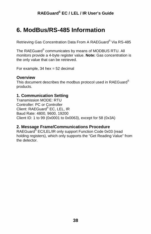
6. ModBus/RS-485 Information Retrieving Gas Concentration Data From A RAEGuardS Via RS-485 The RAEGuardS communicates by means of MODBUS RTU. All monitors provide a 4-byte register value. Note: Gas concentration is the only value that can be retrieved. For example, 34 hex = 52 decimal Overview This document describes the modbus protocol used in RAEGuardS products. 1. Communication Setting Transmission MODE: RTU Controller: PC or Controller Client: RAEGuardS EC, LEL, IR Baud Rate: 4800, 9600, 19200 Client ID: 1 to 99 (0x0001 to 0x0063), except for 58 (0x3A) 2. Message Frame/Communications Procedure RAEGuardS EC/LEL/IR only support Function Code 0x03 (read holding registers), which only supports the “Get Reading Value” from the detector.

RAEGuardS EC / LEL / IR User’s Guide
39
0x03: Read Holding Registers Requesting Message: Device Address
Func-tion Code
Register Address High Byte
Register Address Low Byte
Quantity of Registers High Byte
Quantity of Registers Low Byte
CRC Low Byte
CRC High Byte
Client ID 03 00 08 00 02 CRC CRC Answering Message: Device Address
Function Code
Byte Count
Register Value CRC Low Byte
CRC High Byte
Client ID 03 04 Reading Highest Byte
Reading Higher Byte
Reading High Byte
Reading Low Byte
CRC CRC
Note: The length of data from the detector is 4 bytes. Example: Request: 01 03 00 09 00 02 14 09 Answer: 01 03 04 00 00 00 34 FB E4 Note: The maximum distance should be less than 1 km when using a 1.5 mm2 cable.
RAE Systems by Honeywell World Headquarters
3775 N. First St. San Jose, CA 95134-1708 USA
Phone: 408.952.8200 Toll-Free: 888.723.4800
Fax: 408.952.8480
E-mail (sales support): [email protected] E-mail (technical support): [email protected]
Web Site: www.raesystems.com
RAE Systems Europe Kirstinehøj 23A, DK-2770 Kastrup • Denmark
Tel: +45.8652.5155 • Fax: +45.8652.5177
RAE Systems (Hong Kong) Ltd. Units 1516-18, 15/F, Delta House, 3 On Yiu Street
Shatin, N.T. Hong Kong Web: www.raesystems.cn • Email: [email protected]
Phone: +852.2669.0828
RAE Systems Middle East LOB 7, Ground Floor, Office 19, Jebel Ali Free Zone
Dubai, United Arab Emirates Email: [email protected] • Phone: +971.4.887.5562
P/N 033-4117-E00 Rev A August 2009