Non Destructive Testing - Pressure Testing is a Non-Destructive Test Performed to Ensure the...
12
home | sitemap | about | jobs | abbreviations | fun | question | conversion | links | copyright | misc | contact EXPLORE the WORLD of PIPING DOCS MATL SOCIETIES PIPES FLANGES FITTINGS VALVES BOLTS GASKETS EQPT SPECIALS STEEL DIN STEAM OTHERS Non Destructive Testing Pressure Testing What is meant by Pressure Testing? Pressure Testing is a nondestructive test performed to ensure the integrity of the pressure shell on new pressure equipment, or on previously installed pressure and piping equipment that has undergone an alteration or repair to its boundary(s). Pressure testing is required by most piping codes to verify that a new, modified, or repaired piping system is capable of safely withstanding its rated pressure and is leak tight. Compliance to piping codes may be mandated by regulatory and enforcement agencies, insurance carriers, or the terms of the contract for the construction of the system. Pressure testing, whether or not legally required, serves the useful purpose of protecting workers and the public. Pressure testing may also be used to establish a pressure rating for a component or special system for which it is not possible to establish a safe rating by calculation. A prototype of the component or system is subjected to a gradually increasing pressure until measurable yielding first occurs or, alternatively, to the point of rupture. Then by using derating factors specified in the code, or the standard, appropriate to the component or system, it is possible to establish a design pressure rating from the experimental data. Piping Codes There are a great many codes and standards relating to piping systems. Two codes of major importance for pressure and leak testing are the ASME B31 Pressure Piping Code and the ASME Boiler and Pressure Vessel Code. While these two codes are applicable to many piping systems, other codes or standards may have to be met as required by the authorities, insurance companies, or the owner of the system. Examples might be AWWA standards for water transmission and distribution system piping. The ASME B31 Pressure Piping Code has several sections. They are: ASME B31.1 for Power Piping ASME B31.2 for Fuel Gas Piping ASME B31.3 for Process Piping ASME B31.4 for Liquid Transportation Systems for Hydrocarbons, Liquid Petroleum Gas, Anhydrous Ammonia, and Alcohols ASME B31.5 for Refrigeration Piping ASME B31.8 for Gas Transmission and Distribution Piping Systems ASME B31.9 for Building Services Piping ASME B31.11 for Slurry Transportation Piping Systems The ASME Boiler and Pressure Vessel Code also has several sections which contain pressure and leak testing requirements for piping systems, pressure vessels, and other pressure retaining items. These are: Section I for Power Boilers
-
Upload
anne-wheeler -
Category
Documents
-
view
4 -
download
2
description
Non Destructive Testing
Transcript of Non Destructive Testing - Pressure Testing is a Non-Destructive Test Performed to Ensure the...

home | sitemap | about | jobs | abbreviations | fun | question | conversion | links | copyright | misc | contact
EXPLORE the WORLD of PIPINGDOCS MATL SOCIETIES PIPES FLANGES FITTINGS VALVES BOLTS GASKETS EQPT SPECIALS STEEL DIN STEAM OTHERS
Non Destructive Testing Pressure Testing
What is meant by Pressure Testing?Pressure Testing is a nondestructive test performed to ensure the integrity of the pressure shell onnew pressure equipment, or on previously installed pressure and piping equipment that has undergonean alteration or repair to its boundary(s).
Pressure testing is required by most piping codes to verify that a new, modified, or repaired pipingsystem is capable of safely withstanding its rated pressure and is leak tight. Compliance to pipingcodes may be mandated by regulatory and enforcement agencies, insurance carriers, or the terms ofthe contract for the construction of the system. Pressure testing, whether or not legally required,serves the useful purpose of protecting workers and the public.
Pressure testing may also be used to establish a pressure rating for a component or special system forwhich it is not possible to establish a safe rating by calculation. A prototype of the component orsystem is subjected to a gradually increasing pressure until measurable yielding first occurs or,alternatively, to the point of rupture. Then by using derating factors specified in the code, or thestandard, appropriate to the component or system, it is possible to establish a design pressure ratingfrom the experimental data.
Piping CodesThere are a great many codes and standards relating to piping systems. Two codes of majorimportance for pressure and leak testing are the ASME B31 Pressure Piping Code and the ASME Boilerand Pressure Vessel Code. While these two codes are applicable to many piping systems, other codesor standards may have to be met as required by the authorities, insurance companies, or the owner ofthe system. Examples might be AWWA standards for water transmission and distribution systempiping. The ASME B31 Pressure Piping Code has several sections. They are:
ASME B31.1 for Power PipingASME B31.2 for Fuel Gas PipingASME B31.3 for Process PipingASME B31.4 for Liquid Transportation Systems for Hydrocarbons, Liquid Petroleum Gas, AnhydrousAmmonia, and AlcoholsASME B31.5 for Refrigeration PipingASME B31.8 for Gas Transmission and Distribution Piping SystemsASME B31.9 for Building Services PipingASME B31.11 for Slurry Transportation Piping Systems
The ASME Boiler and Pressure Vessel Code also has several sections which contain pressure and leaktesting requirements for piping systems, pressure vessels, and other pressure retaining items. Theseare:
Section I for Power Boilers

Section III for Nuclear Power Plant ComponentsSection V for Non Destructive ExaminationSection VIII for Pressure VesselsSection X for Fiberglass Reinforced Plastic Pressure VesselsSection XI for In Service Inspection of Nuclear Power Plant Components
There is great similarity with respect to the requirements and procedures for testing among the manycodes. Various leaktesting methods, planning, preparation, execution, documentation, and acceptancestandards for pressure testing will be discussed in this chapter. Equipment, useful for pressure testing,will also be included in the discussion. The material that follows should not be considered a substitutefor a complete knowledge or careful study of the particular code requirement that must be used to testa particular piping system.
LeakTesting MethodsThere are many different methods for pressure and leak testing in the field. Seven of these are:
1. Hydrostatic testing, which uses water or another liquid under pressure2. Pneumatic or gaseousfluid testing, which uses air or another gas under pressure3. A combination of pneumatic and hydrostatic testing, where low pressure air is first used to detect
leaks4. Initial service testing, which involves a leakage inspection when the system is first put into
operation5. Vacuum testing, which uses negative pressure to check for the existence of a leak6. Static head testing, which is normally done for drain piping with water left in a standpipe for a set
period of time7. Halogen and helium leak detection
Hydrostatic Leak TestingHydrostatic testing is the preferred leaktesting method and perhaps the most often used. The mostimportant reason for this is the relative safety of hydrostatic testing compared to pneumatic testing.Water is a much safer fluid test medium than air because it is nearly incompressible. Therefore, theamount of work required to compress water to a given pressure in a piping system is substantially lessthan the work required to compress air, or any other gas, to the same pressure. The work ofcompression is stored in the fluid as a potential energy, which could be released suddenly in the eventof a failure during a pressure test.
A calculation of the potential energy of air compressed to a pressure of 1000 psig (6900 kPa) comparedto the potential energy of the same final volume of water at 1000 psig (6900 kPa) shows a ratio of over2500 to 1. Therefore, the potential damage to surrounding equipment and personnel resulting from afailure during a pressure test is far more serious when using a gaseous test medium. That is not to saythat there is no danger at all in a hydrostatic leak test. There can be substantial danger in ahydrostatic test due to air trapped in the piping. Even if all air is vented from the piping beforepressurizing, workers are well advised to conduct any highpressure test with safety in mind.
Pneumatic Leak TestingThe fluid normally used for a pneumatic test is compressed air, or nitrogen if the source is bottled gas.Nitrogen should not be used in a closed area if the possibility exists that the escaping nitrogen coulddisplace the air in the confined space. Persons have been known to become unconscious under suchcircumstances before realizing they were short of oxygen. Because of the greater danger of injury witha gaseous test medium, the pressure that may be used for visual examination for leaks is lower forsome piping codes than is the case for a hydrostatic test. For example, for pneumatic tests, ASMEB31.1 permits the pressure to be reduced to the lower of 100 psig (690 kPa) or the design pressure

during the examination for leakage.
Combination Pneumatic and Hydrostatic TestingA low air pressure, most often 25 psig, (175 kPa) is first used to see if there are major leaks. This lowpressure reduces the danger of personal injury but still enables major leaks to be quickly located.Repairs, if needed, can then be done before the hydrostatic test. This method can be very effective insaving time, particularly if it takes a long time to fill a system with water only to find leaks on the firsttry. If leaks are found in a hydrostatic test, it will take longer to remove the water and dry the pipingsufficiently to make repairs.
Hydrostaticpneumatic leak testing is different from the twostep test in the preceding paragraph. Inthis case the pressure test is conducted with a combination of air and water. For example, a pressurevessel designed to contain a process liquid with a vapor phase or air above the liquid may have beendesigned to support the weight of liquid to a certain maximumexpected height of liquid. If the vesselwas not designed to support the weight when completely filled with liquid, it would be possible to testthis vessel only if it was partially filled with process fluid to a level duplicating the effect of themaximumexpected level.
Initial Service Leak TestingThis category of testing is limited by the codes to certain situations. For example, ASME B31.3 limitsthe use of this technique to category D fluid service. Category D fluid services are defined asnonhazardous to humans and must operate below 150 psi (1035 kPa) and at temperatures between20 and 366°F (29 and 185°C). ASME Code B31.1, section 137.7.1, does not allow initial servicetesting of boiler external piping. However, that same section of ASME B31.1 permits initial servicetesting of other piping systems if other types of leak testing are not practical. Initial service testing isalso applicable to inspection of nuclear power plant components by Section XI of the ASME Boiler andPressure Vessel Code. As indicated, this test is usually run when the system is first put into operation.The system is gradually raised to normal operating pressure as required in ASME B31.1 or designpressure as required in ASME B31.3. It is then maintained at that pressure while an examination forleaks is conducted.
Vacuum Leak TestingVacuum leak testing is an effective way to determine whether or not there is a leak anywhere in thesystem. This is normally done by drawing a vacuum on the system and trapping the vacuum withinthe system. A leak is indicated if the trapped vacuum rises toward atmospheric pressure. Amanufacturer of components quite often uses this type of leak test as a production leak test. However,it is very difficult to determine the location or locations of a leak if one exists. Smoke generators havebeen used to determine the piping location where smoke is drawn into the piping. This is very difficultto utilize unless the leak is sufficiently great to draw all or most of the smoke into the pipe. If there issubstantially more smoke generated than can be drawn into the pipe, the smoke that dissipates intothe surrounding air can easily hide the leak location. Obviously, this method is not suitable for testingthe piping at or above the operating pressure unless the piping is to be operated at a vacuum.
StaticHead Leak TestingThis test method is sometimes called a drop test because a drop in the water level in the openstandpipe, added to the system to create the required pressure, is an indication of a leak. Once thesystem and standpipe is filled with water, the standpipe level is measured and noted. After a requiredhold period, the height is rechecked and any decrease in level and the hold period are recorded. Anyleak location is determined by visual inspection.
Halogen and Helium Leak TestingThese test methods use a tracer gas to identify leakage location and leakage quantity. In the case of
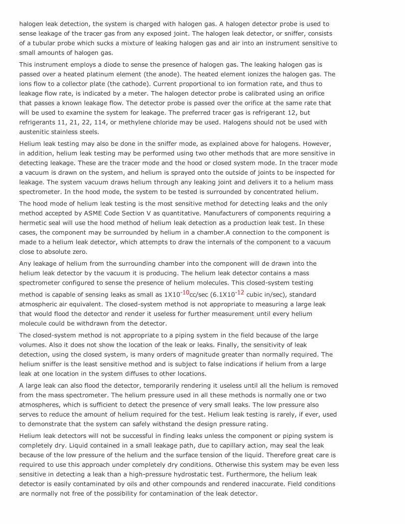
halogen leak detection, the system is charged with halogen gas. A halogen detector probe is used tosense leakage of the tracer gas from any exposed joint. The halogen leak detector, or sniffer, consistsof a tubular probe which sucks a mixture of leaking halogen gas and air into an instrument sensitive tosmall amounts of halogen gas.
This instrument employs a diode to sense the presence of halogen gas. The leaking halogen gas ispassed over a heated platinum element (the anode). The heated element ionizes the halogen gas. Theions flow to a collector plate (the cathode). Current proportional to ion formation rate, and thus toleakage flow rate, is indicated by a meter. The halogen detector probe is calibrated using an orificethat passes a known leakage flow. The detector probe is passed over the orifice at the same rate thatwill be used to examine the system for leakage. The preferred tracer gas is refrigerant 12, butrefrigerants 11, 21, 22, 114, or methylene chloride may be used. Halogens should not be used withaustenitic stainless steels.
Helium leak testing may also be done in the sniffer mode, as explained above for halogens. However,in addition, helium leak testing may be performed using two other methods that are more sensitive indetecting leakage. These are the tracer mode and the hood or closed system mode. In the tracer modea vacuum is drawn on the system, and helium is sprayed onto the outside of joints to be inspected forleakage. The system vacuum draws helium through any leaking joint and delivers it to a helium massspectrometer. In the hood mode, the system to be tested is surrounded by concentrated helium.
The hood mode of helium leak testing is the most sensitive method for detecting leaks and the onlymethod accepted by ASME Code Section V as quantitative. Manufacturers of components requiring ahermetic seal will use the hood method of helium leak detection as a production leak test. In thesecases, the component may be surrounded by helium in a chamber.A connection to the component ismade to a helium leak detector, which attempts to draw the internals of the component to a vacuumclose to absolute zero.
Any leakage of helium from the surrounding chamber into the component will de drawn into thehelium leak detector by the vacuum it is producing. The helium leak detector contains a massspectrometer configured to sense the presence of helium molecules. This closedsystem testing
method is capable of sensing leaks as small as 1X10¹⁰cc/sec (6.1X10¹² cubic in/sec), standardatmospheric air equivalent. The closedsystem method is not appropriate to measuring a large leakthat would flood the detector and render it useless for further measurement until every heliummolecule could be withdrawn from the detector.
The closedsystem method is not appropriate to a piping system in the field because of the largevolumes. Also it does not show the location of the leak or leaks. Finally, the sensitivity of leakdetection, using the closed system, is many orders of magnitude greater than normally required. Thehelium sniffer is the least sensitive method and is subject to false indications if helium from a largeleak at one location in the system diffuses to other locations.
A large leak can also flood the detector, temporarily rendering it useless until all the helium is removedfrom the mass spectrometer. The helium pressure used in all these methods is normally one or twoatmospheres, which is sufficient to detect the presence of very small leaks. The low pressure alsoserves to reduce the amount of helium required for the test. Helium leak testing is rarely, if ever, usedto demonstrate that the system can safely withstand the design pressure rating.
Helium leak detectors will not be successful in finding leaks unless the component or piping system iscompletely dry. Liquid contained in a small leakage path, due to capillary action, may seal the leakbecause of the low pressure of the helium and the surface tension of the liquid. Therefore great care isrequired to use this approach under completely dry conditions. Otherwise this system may be even lesssensitive in detecting a leak than a highpressure hydrostatic test. Furthermore, the helium leakdetector is easily contaminated by oils and other compounds and rendered inaccurate. Field conditionsare normally not free of the possibility for contamination of the leak detector.
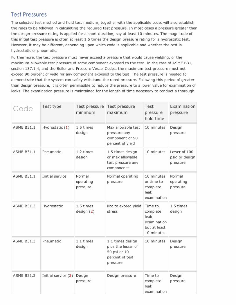
Test PressuresThe selected test method and fluid test medium, together with the applicable code, will also establishthe rules to be followed in calculating the required test pressure. In most cases a pressure greater thanthe design pressure rating is applied for a short duration, say at least 10 minutes. The magnitude ofthis initial test pressure is often at least 1.5 times the design pressure rating for a hydrostatic test.However, it may be different, depending upon which code is applicable and whether the test ishydrostatic or pneumatic.
Furthermore, the test pressure must never exceed a pressure that would cause yielding, or themaximum allowable test pressure of some component exposed to the test. In the case of ASME B31,section 137.1.4, and the Boiler and Pressure Vessel Codes, the maximum test pressure must notexceed 90 percent of yield for any component exposed to the test. The test pressure is needed todemonstrate that the system can safely withstand the rated pressure. Following this period of greaterthan design pressure, it is often permissible to reduce the pressure to a lower value for examination ofleaks. The examination pressure is maintained for the length of time necessary to conduct a thorough
Code Test type Test pressureminimum
Test pressuremaximum
Testpressurehold time
Examinationpressure
ASME B31.1 Hydrostatic (1) 1.5 timesdesign
Max allowable testpressure anycomponent or 90percent of yield
10 minutes Designpressure
ASME B31.1 Pneumatic 1.2 timesdesign
1.5 times designor max allowabletest pressure anycomponenet
10 minutes Lower of 100psig or designpressure
ASME B31.1 Initial service Normaloperatingpressure
Normal operatingpressure
10 minutesor time tocompleteleakexamination
Normaloperatingpressure
ASME B31.3 Hydrostatic 1,5 timesdesign (2)
Not to exceed yieldstress
Time tocompleteleakexaminationbut at least10 minutes
1.5 timesdesign
ASME B31.3 Pneumatic 1.1 timesdesign
1.1 times designplus the lesser of50 psi or 10percent of testpressure
10 minutes Designpressure
ASME B31.3 Initial service (3) Designpressure
Design pressure Time tocompleteleakexamination
Designpressure

ASME I Hydrostatic 1.5 times maxallowableworkingpressure (4)
Not to exceed 90percent yieldstress
Notspecified,typically 1hr
Max allowableworkingpressure (4)
ASME IIIDivision 1Subsection NB
Hydrostatic 1.25 timessystem designpressure (5)
Not to exceedstress limits ofdesign section NB3226 or maximumtest pressure ofany systemcomponenet (5)
10 minutes Greater ofdesignpressure or0,75 timestest pressure
ASME IIIDivision 1Subsection NB
Pneumatic 1.25 timessystem designpressure (6)
Not to exceedstress limits ofdesign section NB3226 or maximumtest pressure ofany systemcomponenet
10 minutes Greater ofdesignpressure or0,75 timestest pressure
ASME IIIDivision 1Subsection NC
Hydrostatic 1.5 timessystem designpressure
If minimum testpressure exceededby 6 percentestablish limit bythe lower ofanalysis of all testloadings ormaximum testpressure of anycomponenet
10 or 15minutes perinch ofdesignminimumwallthicknessfor pumpsand Valves
Greater ofdesignpressure or0,75 timestest pressure
ASME IIIDivision 1Subsection NC
Pneumatic 1.25 timessystem designpressure
If minimum testpressure exceededby 6 percentestablish limit bythe lower ofanalysis of all testloadings ormaximum testpressure of anycomponenet
10 minutes Greater ofdesignpressure or0,75 timestest pressure
ASME IIIDivision 1Subsection ND
Hydrostatic 1.5 timessystem designpressure forcompletedcomponents,1,25 timessystem designpressure forpiping systems
If minimum testpressure exceededby 6 percentestablish limit bythe lower ofanalysis of all testloadings ormaximum testpressure of anycomponenet
10 minutes Greater ofdesignpressure or0,75 timestest pressure

ASME IIIDivision 1Subsection ND
Pneumatic 1.25 timessystem designpressure
If minimum testpressure exceededby 6 percentestablish limit bythe lower ofanalysis of all testloadings ormaximum testpressure of anycomponenet
10 minutes Greater ofdesignpressure or0,75 timestest pressure
Notes:
1. Boiler external piping must be hydrostatic tested in accordance with PG99 of ASMECode Section I.
2. ASME B31.3 hydrostatic pressure must be raised above 1.5 times design pressure inproportion to yield strength at test temperature divided by strength at designtemperature but not to exceed yield strength at test temperature. Where a vessel isinvolved whose design pressure is less than the piping and where vessel cannot beisolated, the piping and vessel can be tested together at vessel test pressure providedvessel test pressure is not less than 77 percent of piping test pressure.
3. ASME B31.3 initial service testing permitted only for piping in category D service.
4. ASME Code Section I hydrostatic test pressure at temperature of at least 70°F (21°C)and examination pressure at temperature less than 120°F (49°C). For a forcedflowsteam generator with pressure parts designed for different pressure levels, the testpressure should be at least 1.5 times the maximum allowable working pressure at thesuperheater outlet but not less than 1.25 times the maximum allowable workingpressure of any part of the boiler.
5. ASME Code Section III, Division 1, subsection NB, test pressure limits defined insection NB3226; also components containing brazed joints and Valves to be tested at1.5 times systemdesign pressure prior to installation.
6. ASME Code Section III, Division 1, subsection NB, pneumatic test pressure forcomponents partially filled with water shall not be less than 1.25 times systemdesignpressure.
Pressure Equipment FailurePressure vessel and piping systems are widely used throughout industry and contain a very largeconcentration of energy. Despite the fact that their design and installation comply with federal, stateand local regulations and recognized industrial standards, there continue to be serious pressureequipment failures.
There are many reasons for pressure equipment failure: degradation and thinning of materials duringperation, aging, hidden flaws during fabrication, etc.. Fortunately, periodic testing and internal andexternal inspections significantly improve the safety of a pressure vessel or piping system. A goodtesting and inspection program is based on development of procedures for specific industries or typesof vessels.
A number of accidents has served to focus attention on the hazards and risks associated with storage,handling, and transfer of fluids under pressure. When pressure vessels do fail, it is typically the resultof shell failure resulting from corrosion and erosion (more than 50 percent shell failures).

New constructed vessel ripped open during a hydrotest
All pressure vessels have their own peculiar hazards, including great stored potential force, points ofwear and corrosion, and possible failure of overpressure and temperature control safety devices.Government and industry have responded to the need for improved pressure systems testing byproducing standards and regulations specifying general pressure safety requirements (ASME Boiler andPressure Vessel Code, DOE Pressure Safety Guidelines and others).These regulations outline requirements for implementation of a pressure testing safety program. It iscritical that design and operating personnel use these standards as benchmark criteria for writing andimplementing a pressure testing safety program.
Pressure Testing ProgramA good pressure testing safety program should detect fabrication defects and deterioration from aging,cracking, corrosion and other factors before they cause vessel failure and to determine (1) if the vesselcan continue to be operated at the same pressure, (2) what measures of control and repair may beneeded so that the pressure system can be operated at the original pressure, and (3) whether pressuremust be reduced in order to operate the system safely.
All companies, working with pressurized equipment, almost all have expanded engineering guidelinesfor testing of pressure vessels and piping systems. These guidelines are prepared in accordance withthe pressure safety standards of OSHA, DOT, ASME, local, state, and other federal codes andstandards.
The documentation includes definition of the responsibilities of engineering, management, and safetypersonnel; the general requirements for equipment and materials; procedures for hydrostatic andpneumatic testing to verify the integrity of a system and its components; and guidelines for a pressuretesting plan, emergency procedures, documentation, and hazard control measures. These measuresinclude pressure release control, protection against the effects of noise exposure, environmental andpersonal monitoring, and protection from the presence of toxic or flammable gases and high pressures.
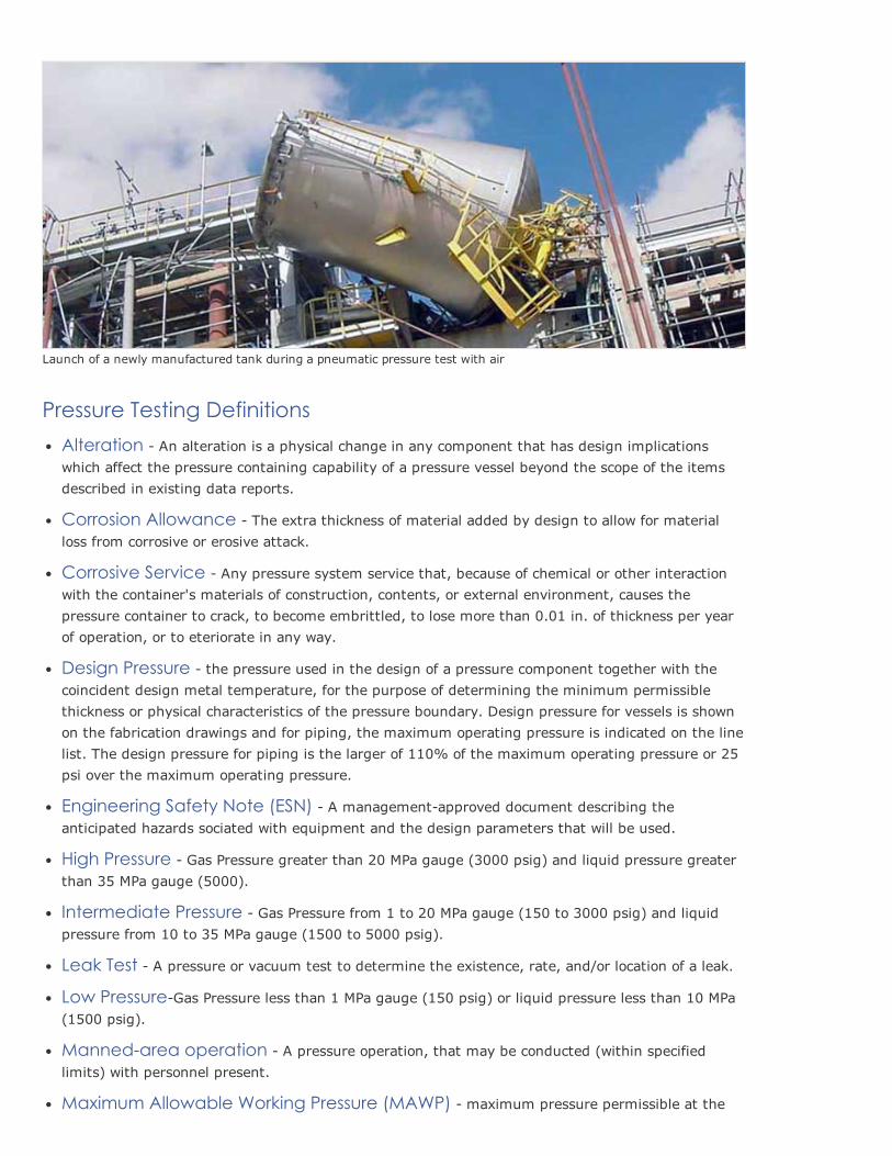
Launch of a newly manufactured tank during a pneumatic pressure test with air
Pressure Testing DefinitionsAlteration An alteration is a physical change in any component that has design implicationswhich affect the pressure containing capability of a pressure vessel beyond the scope of the itemsdescribed in existing data reports.
Corrosion Allowance The extra thickness of material added by design to allow for materialloss from corrosive or erosive attack.
Corrosive Service Any pressure system service that, because of chemical or other interactionwith the container's materials of construction, contents, or external environment, causes thepressure container to crack, to become embrittled, to lose more than 0.01 in. of thickness per yearof operation, or to eteriorate in any way.
Design Pressure the pressure used in the design of a pressure component together with thecoincident design metal temperature, for the purpose of determining the minimum permissiblethickness or physical characteristics of the pressure boundary. Design pressure for vessels is shownon the fabrication drawings and for piping, the maximum operating pressure is indicated on the linelist. The design pressure for piping is the larger of 110% of the maximum operating pressure or 25psi over the maximum operating pressure.
Engineering Safety Note (ESN) A managementapproved document describing theanticipated hazards sociated with equipment and the design parameters that will be used.
High Pressure Gas Pressure greater than 20 MPa gauge (3000 psig) and liquid pressure greaterthan 35 MPa gauge (5000).
Intermediate Pressure Gas Pressure from 1 to 20 MPa gauge (150 to 3000 psig) and liquidpressure from 10 to 35 MPa gauge (1500 to 5000 psig).
Leak Test A pressure or vacuum test to determine the existence, rate, and/or location of a leak.
Low PressureGas Pressure less than 1 MPa gauge (150 psig) or liquid pressure less than 10 MPa(1500 psig).
Mannedarea operation A pressure operation, that may be conducted (within specifiedlimits) with personnel present.
Maximum Allowable Working Pressure (MAWP) maximum pressure permissible at the

top of a vessel in its normal operating position at the operating temperature specified for thepressure. It is the least of the values found for maximum allowable working pressure for any of theessential parts of the vessel by the principles established in ASME Section VIII. The MAWP is shownon the vessel nameplate. The MAWP may be taken same as the design pressure, but for the mostpart the MAWP is based on the fabricated thickness minus the corrosion allowance. MAWP applies topressure vessels only.
Maximum Design Temperature is the maximum temperature used in the design and shallnot be less than the maximum operating temperature.
Maximum Operating Pressure (MOP) The highest pressure expected during operation. Thisis usually 1020% below the MAWP.
Minimum Allowable Metal Temperature (MAMT) The minimum temperature for anexisting vessel to sustain the testing or operating conditions with a low risk of brittle fracture. TheMAMT is determined by an evaluation for pressure vessels built prior to 1987. This term is used inAPI RP 579 for the brittle fracture evaluation of existing equipment. It may be a singletemperature, or an envelope of acceptable operating temperatures as a function of pressure.
Minimum Design Metal Temperature (MDMT) The minimum metal temperature used inthe design of a pressure vessel. The MDMT is an ASME Code term and normally shown on the vesselnameplate or U1 Form for vessels designed per ASME Section VIII, Division 1, 1987 edition orlater.
Mpa Absolute pressure in SI units. 1 atmosphere (14.7 psig) is equal to 0.1 MPa.
Operational Safety Procedure (OSP) The Document used to describe the controlsnecessary to ensure that the risks associated with a potentially hazardous research project or uniqueactivity are at an acceptable level.
Pressure Equipment Any equipment, e.g., vessels, manifolds, piping, or other components,that operates above or below (in the case of vacuum equipment) atmospheric pressure.
Pressure Vessel A relatively highvolume pressure component (such as a spherical or cylindricalcontainer) with a cross section larger than the associated piping.
Proof Test A test in which equipment prototypes are pressurized to determine the actual yield orfailure (burst) pressure (used to calculate the MAWP).
Remote Operation A pressure operation, that may not be conducted with personnel present.The equipment must be installed in test cells, behind certified barricades, or be operated from asafe location.
Safety Factor (SF) The ratio of the ultimate (i.e., burst or failure) pressure (measured orcalculated) to the MAWP. A Safety Factor related to something other than the failure pressureshould be identified with an appropriate subscript.
Codes, Standards and References
American Society of Mechanical Engineers (ASME)Boiler and Pressure Vessel Code: Section VIII Pressure VesselsASME B31.3 Chemical Plant and Petroleum Refinery PipingASME B16.5 Pipe Flanges and Flanged Fittings
American Society for Testing and Materials (ASTM)

ASTM E 1003 Standard Test Method for Hydrostatic Leak Testing
American Petroleum Institute (API)RP 1110 Pressure Testing of Steel Pipelines for the Transportation of Gas, Petroleum Gas, HazardousLiquids...API 510 Maintenance, Inspection, Rating, Repair, and AlterationAPI 560 Fired Heaters for General Refinery ServicesAPI 570 Inspection, Repair, Alteration, and Rerating of InService Piping SystemsAPI 579 Draft of API Recommended Practice for FitnessForService
Robert B. AdamsPresident and CEO EST Group, Inc. Harleysville, Pennsylvania
Interesting articles about pressure testing failurePressure Vessel Failure during Pneumatic Test
Pressure Vessel Failure during Hydro Test
Pressure Vessel Failure during Air Test
Remark(s) of the Author...
Pressure Testing according to ASME B31.3Piping systems are typically designed and built per an applicable code. Certainly the use ofASME B31.3 could be applicable to ships carrying oil, but you should really be following thecode that the piping system was designed to. Since I'm familiar with B31.3 and not theEuropean (or other country's) equivalent, I'll base this response on B31.3.
ASME B31.3 requires "leak testing" of the piping system. This is not a structural test, it is onlya test to determine if there are points within the system that are leaking.* On the other hand,there are codes which may require a structural test such as is done by the boiler and pressurevessel code. In that case, the hydrostatic test is performed to verify that the vessel andattached piping is structurally sound, not just leak tight.
ASME B31.3, Para. 345.1 states:Prior to initial operation, and after completion of the applicable examinations required by para.341, each piping system shall be tested to ensure tightness. The test shall be a hydrostatic leaktest in accordance with para. 345.4 except as provided herein.
Where the owner considers a hydrostatic leak test impractical, either a pneumatic test inaccordance with para. 345.5 or a combined hydrostaticpneumatic test in accordance with para.345.6 may be substituted, recognizing the hazard of energy stored in compressed gas.
So per the code, a leak test using air may be performed if the system owner considers thehydrostatic test to be impractical.
It's important to understand that the pressure at which the test is performed is a function ofthe design pressure. Design pressure is a function of the allowable stress limits on the pipingwhich is also a function of operating temperature.
For a hydrostatic test, para. 345.4.2 requires a pressure of not less than 1.5 times thedesign pressure.For a pneumatic test, para. 345.5.4 requires a pressure of not less than 110% of designpressure.

Next step is for an engineer (preferably the piping system designer or stress analyst) to createpressure test procedures. These pressure test procedures look at the possibility of lowtemperature brittle failure, which may be a concern at the temperatures you're referring to.The pressure test procedures are actually a set of procedures (typically) which include suchthings as method of pressurizing system, valve positions, removal of relief devices, isolation ofportions of the piping system, etc.
Regarding the low temperature, para. 345.4.1 states: "The fluid shall be water unless there is apossibility of damage due to freezing or to adverse effects of water on the piping or the process(see para. F345.4.1). In that case, another suitable nontoxic liquid may be used." Soglycol/water is allowed.
If the test is to be done pneumatically, test pressure should be raised to 25 psi at which time apreliminary check shall be made, including examination of all joints. The use of a lowtemperature bubble fluid is highly advisable.
So to conclude:1. If the specification you've been given is to perform a hydro test at 16 bar, then that should
be 1.5 times the design pressure of 10.67 bar. Per B31.3, a pneumatic test should thereforebe performed not at 16 bar, but at 1.1 times the design pressure or 11.7 bar. Run thepneumatic pressure only as high as 11.7 bar.
2. The possibility of brittle failure should be reviewed by the appropriate engineer. In the caseof temperature below 0 C, the material used should be examined to verify it is not below theminimum useable temperature for that steel.
3. A cognizant engineer needs to produce a set of pressure test procedures. Those proceduresneed to indicate what sections of pipe are being tested, what positions valves should beplaced in, what relief devices need to be removed (or installed), etc.
4. The pneumatic test needs to start at 25 psig and a preliminary examination for leaksperformed prior to increasing pressure.
5. Most important, the cognizant engineer must also examine the piping design specificationfor all requirements pertaining to leak or pressure testing.
Although B31.3 describes this as a "leak test", when performed hydrostatically at 1.5 timesdesign, it is in affect, a structural test.
Please read the article: The Unitd States Department of Labor OSHA
© Werner Sölken 2008 2014. All rights reserved.
Do not worry about your difficulties in Mathematics. I can assure you mine are still greater. Albert Einstein