Non-Destructive Testing of Rail (for Internal & Surface ...
29
Division / Business Unit: Corporate Services & Safety Function: Track & Civil Document Type: Standard © Australian Rail Track Corporation Limited (ARTC) Disclaimer This document has been prepared by ARTC for internal use and may not be relied on by any other party without ARTC’s prior wri tten consent. Use of this document shall be subject to the terms of the relevant contract with ARTC. ARTC and its employees shall have no liability to unauthorised users of the information for any loss, damage, cost or expense incurred or arising by reason of an unauthorised user using or relying upon the information in this document, whether caused by error, negligence, omission or misrepresentation in this document. This document is uncontrolled when printed. Authorised users of this document should visit ARTC’s intranet or extranet (www.artc.com.au) to access the latest version of this document. Page 1 of 29 Non-Destructive Testing of Rail (for Internal & Surface Defects) ETE-01-03 Applicability ARTC Network Wide SMS Publication Requirement Internal / External Primary Source NSW Standards TES 03, TES 05, TEP 15, TEP 16, TEP 17, TEP 18, TEP 19, the Rail Fail Form and Manual RC 2407. Document Status Version # Date Reviewed Prepared by Reviewed by Endorsed Approved 1.9 14 Jun 20 Standards Stakeholders Manager Standards General Manager Technical Standards 14/06/2020 Amendment Record Amendment Version # Date Reviewed Clause Description of Amendment 1.0 10 Sep 08 First issue 1.1 14 Jan 09 Various Minor editorial corrections to cross references identified following Risk & Safety Committee approval and Regulator notification 1.2 21 Jun 10 4.7 (Table 6) Includes the option of hand testing when the signal from the zero probe is lost as per Instruction ETI-01-06 which is now withdrawn. Applicability and disclaimer updated.
Transcript of Non-Destructive Testing of Rail (for Internal & Surface ...

Division / Business Unit: Corporate Services & Safety
Function: Track & Civil
Document Type: Standard
© Australian Rail Track Corporation Limited (ARTC)
Disclaimer
This document has been prepared by ARTC for internal use and may not be relied on by any other party without ARTC’s prior wri tten consent. Use of this document shall be subject
to the terms of the relevant contract with ARTC.
ARTC and its employees shall have no liability to unauthorised users of the information for any loss, damage, cost or expense incurred or arising by reason of an unauthorised user
using or relying upon the information in this document, whether caused by error, negligence, omission or misrepresentation in this document.
This document is uncontrolled when printed.
Authorised users of this document should visit ARTC’s intranet or extranet (www.artc.com.au) to access the latest version of this document.
Page 1 of 29
Non-Destructive Testing of Rail (for
Internal & Surface Defects)
ETE-01-03
Applicability
ARTC Network Wide SMS
Publication Requirement
Internal / External
Primary Source
NSW Standards TES 03, TES 05, TEP 15, TEP 16, TEP 17, TEP 18, TEP 19, the Rail Fail Form and Manual RC
2407.
Document Status
Version
#
Date
Reviewed
Prepared by Reviewed by Endorsed Approved
1.9 14 Jun 20 Standards Stakeholders Manager
Standards
General Manager
Technical Standards
14/06/2020
Amendment Record
Amendment
Version #
Date
Reviewed
Clause Description of Amendment
1.0 10 Sep 08 First issue
1.1 14 Jan 09 Various Minor editorial corrections to cross references identified following Risk &
Safety Committee approval and Regulator notification
1.2 21 Jun 10 4.7
(Table 6)
Includes the option of hand testing when the signal from the zero probe is
lost as per Instruction ETI-01-06 which is now withdrawn. Applicability
and disclaimer updated.

Non-Destructive Testing of Rail (for Internal & Surface Defects)
ETE-01-03
This document is uncontrolled when printed. Version Number: 1.9 Date Reviewed: 14 Jun 20 Page 2 of 29
1.3 30 Jun 10 4.7
(Table 6)
Updated for clarification regarding action for complete loss of detection by
zero probe - speed restriction of 40km/h has been reinstated for rail risk
score 1 and note added to all rail risk scores that hand testing is
acceptable.
1.4 6 Nov 12 Table 6 Revised table 6 to allow 7 days for NDT Ultrasonic testers to check on rail
which is untestable by the Ultrasonic Test Car, without imposing TSR.
Response time to return form ETE0103-03 to Infrastructure Manager
increased from 1 to 3 days, as well as minor clarifications in table
regarding timing of rectification, as well as reformatting of table for ease
of reading. Minor editorial changes throughout document.
1.5 21 Jan 14 3.1.1 Updated to include note that any changes to test frequency must follow
ARTC Change Management Process, including notification to Regulators.
1.6 06 Oct 16 All
1.1
1.3
2.1 & 2.4
4.2.2
4.5.1
4.5.2
4.5.4
4.7
6.2
6.3
Remove reference to organisational structure roles. Editorial and
clarifications. Rebranded.
Remove a reference to a clause in Track and Civil CoP Rail Section 1
which refers back to this standard.
Changes 35o to 38oc to correctly describe the angled probe.
Clarity on procedure and standard for qualification. Changed superseded
Australian Standard AS 3998 with AS ISO 9712.
Added dimensions for the rail specific calibration block.
New clause for the introductory information and added type of
instrumentation.
Added additional information on the capability for the specified probes.
Replaced recommended with mandate to align with AS 2207.
Updated to address squatted rail issues.
New clause for naming system of defects.
Added additional requirements for indications exceeding 40%.
1.7 10 Oct 17 All 1 3.1 3.1.1 3.1.2 3.3 4.6 5
Added table of figures and table of tables. Figures and tables
renumbered. Editorial.
Created a purpose section (1.1), scope section (1.2) and responsibility
(1.4)
Simplified heading by removing description that is part of scope
Removed safety limits from the heading. Deleted reference to annual
publication of the test frequency in the Technical Maintenance Plan.
Added information for clarity on inspection frequency of Points and
Crossings and Crossovers.
Deleted
Clarification on testing of areas of the Points and Crossings and a figure
added for illustration.
Deleted information on frequency of testing which is addressed
elsewhere.
Clarifying information on the programming and use of alternative NDT
techniques.
1.8 25 Jul 18 7.2.1, 7.3 Updated minimum recording requirement of NDT.

Non-Destructive Testing of Rail (for Internal & Surface Defects)
ETE-01-03
This document is uncontrolled when printed. Version Number: 1.9 Date Reviewed: 14 Jun 20 Page 3 of 29
1.9 14 Jun 20 All Figure 3-1 4.7 7.2.1, 7.2.3, 7.3 8.1.1 8.1.2 8.3
Editorial changes (captions, heading numbering and style).
Added figure to illustrate testing locations in direction of car travel.
Clarification on understanding and responding to shielding.
Revised data required in reports.
Revise paint marking requirements.
Added use of GPS coordinates for defect location.
Changed “top surface straightness and alignment” to “weld geometry”.

Non-Destructive Testing of Rail (for Internal & Surface Defects)
ETE-01-03
This document is uncontrolled when printed. Version Number: 1.9 Date Reviewed: 14 Jun 20 Page 4 of 29
Table of Contents
Table of Contents ............................................................................................................................................. 4
Table of Figures ........................................................................................................................................ 6
Table of Tables ......................................................................................................................................... 6
1 Introduction ............................................................................................................................................. 7
1.1 Purpose .......................................................................................................................................... 7
1.2 Scope ............................................................................................................................................. 7
1.3 Document Owner ........................................................................................................................... 7
1.4 Responsibilities .............................................................................................................................. 7
1.5 Related documents ........................................................................................................................ 7
1.6 Limitations of this Standard: ........................................................................................................... 8
1.7 Definitions ....................................................................................................................................... 8
2 Personnel Qualifications ....................................................................................................................... 9
2.1 Non-Destructive Testing Qualifications .......................................................................................... 9
2.2 Visual Capability ............................................................................................................................. 9
2.3 Records .......................................................................................................................................... 9
2.4 Re-Certification............................................................................................................................... 9
3 Non-Destructive Testing Requirements ............................................................................................. 10
3.1 Existing Rail and Welds ............................................................................................................... 10
3.1.1 Testing and classification of defects ............................................................................................. 10
3.1.2 Testing Frequency: principles of rail break reduction ................................................................... 10
3.1.3 Management of testing frequency ................................................................................................ 10
3.2 Points and Crossings testability issues ........................................................................................ 12
3.3 NDT of New Welds (Aluminothermic, Wire Feed (Fluxcore) and Flashbutt) ............................... 13
3.3.1 General ......................................................................................................................................... 13
3.3.2 Ultrasonic Inspection of Welds ..................................................................................................... 13
3.3.3 Visual Inspection of Welds ............................................................................................................ 13
3.3.4 Geometric Inspection of Welds ..................................................................................................... 13
3.3.5 Inspection of Punch Marks ........................................................................................................... 13
4 Ultrasonic Testing ................................................................................................................................ 14
4.1 General Guidance to Ultrasonic Testing Philosophy ................................................................... 14
4.2 Calibration Process ...................................................................................................................... 14
4.2.1 Calibration and Equipment Inspection Periods ............................................................................. 14
4.2.2 Calibration Blocks ......................................................................................................................... 14
4.2.3 Calibration Settings for Hand Test Probes .................................................................................... 15

Non-Destructive Testing of Rail (for Internal & Surface Defects)
ETE-01-03
Table of Contents
This document is uncontrolled when printed. Version Number: 1.9 Date Reviewed: 14 Jun 20 Page 5 of 29
4.2.4 Continuous Test Car Calibration ................................................................................................... 15
4.2.5 Pre-test Checks ............................................................................................................................ 16
4.3 Environmental Requirements Ambient Temperature ................................................................... 16
4.4 Equipment Requirements ............................................................................................................. 16
4.4.1 Resolution ..................................................................................................................................... 16
4.5 Equipment Technical Specifications ............................................................................................ 17
4.5.1 General ......................................................................................................................................... 17
4.5.2 Handheld Ultrasonic Equipment ................................................................................................... 17
4.5.3 Rail Mounted Continuous Ultrasonic Testing Equipment .............................................................. 18
4.5.4 Couplant ....................................................................................................................................... 18
4.6 Continuous Ultrasonic Testing ..................................................................................................... 19
4.6.1 Management of Human Factors ................................................................................................... 19
4.7 Assessment Required of any Ultrasonic Shielding ...................................................................... 19
5 Alternative Non-Destructive Testing Techniques ............................................................................. 22
6 Classifying Defects .............................................................................................................................. 23
6.1 Naming System of Defects ........................................................................................................... 23
6.2 Sizing Defects .............................................................................................................................. 24
7 Recording and Reporting Requirements for Rails and Welds ........................................................ 25
7.1 Format of Reports ........................................................................................................................ 25
7.2 Inspection Report ......................................................................................................................... 25
7.2.1 Ultrasonic Test Records ............................................................................................................... 25
7.2.2 Weld Test Records ....................................................................................................................... 25
7.2.3 Defect Reports .............................................................................................................................. 26
7.3 Shielding Reports ......................................................................................................................... 27
8 Site Marking .......................................................................................................................................... 28
8.1 Rail Defect Marking ...................................................................................................................... 28
8.1.1 GPS Coordinates .......................................................................................................................... 28
8.1.2 Paint Marking ................................................................................................................................ 28
8.2 Weld Quality Examination Marking .............................................................................................. 28

Non-Destructive Testing of Rail (for Internal & Surface Defects)
ETE-01-03
Table of Contents
This document is uncontrolled when printed. Version Number: 1.9 Date Reviewed: 14 Jun 20 Page 6 of 29
Table of Figures
Figure 3-1: Test capability depending on travel direction of the rail flaw detection car ................................... 12
Figure 4-1: Rail Specific Gain Calibration Block .............................................................................................. 15
Figure 6-1: Internal rail defects definitions ....................................................................................................... 23
Figure 6-2: Definition of Defect Dimensions .................................................................................................... 24
Figure 8-2: Satisfactory Weld quality – Marking example ............................................................................... 29
Table of Tables
Table 4-1: Calibration Schedule for Ultrasonic Testing Equipment ................................................................. 14
Table 4-2: Calibration Settings ........................................................................................................................ 15
Table 4-3: Resolution requirements ................................................................................................................ 16
Table 4-4: Ultrasonic Probes for Handheld Rail Testing 1, 3 ............................................................................ 17
Table 4-5: Minimum Ultrasonic Probes for Continuous Rail Testing ............................................................... 18
Table 4-6: Causes of shielding ........................................................................................................................ 19
Table 4-7: Assessment of shielding, response times and actions .................................................................. 21

Non-Destructive Testing of Rail (for Internal & Surface Defects)
ETE-01-03
Introduction
This document is uncontrolled when printed. Version Number: 1.9 Date Reviewed: 14 Jun 20 Page 7 of 29
1 Introduction
1.1 Purpose
This standard sets requirements for non-destructive testing (NDT) of rail and welds.
This includes, but is not limited to:
• Ultrasonic Testing by:
o Handheld Equipment
o Trolley
o Rail mounted continuous testing equipment
• Dye Penetrant Testing
• Magnetic Particle Testing
• Visual Inspection
1.2 Scope
This standard applies to all track, including turnouts, where detailed inspection of rails and welds is
carried out as per Section 1.
This standard also applies in tracks where, although detailed inspection is not mandated, an ad hoc
inspection has been directed by corridor management due to condition or operating circumstance.
1.3 Document Owner
The Manager Standards is the document owner and is the initial point of contact for all queries
relating to this Standard.
1.4 Responsibilities
The authority with overall responsibility for the delivery of safe and reliable track and civil
infrastructure for the business unit, or their delegate, is responsible for the implementation of this
standard.
1.5 Related documents
This standard should be read in conjunction with;
• ARTC Track & Civil Code of Practice (T&C CoP) Section 1: Rail and related standards
• AS 1085.20 Railway track material – Welding of steel rail
• AS 2083 Calibration blocks and their methods of use in ultrasonic testing
• AS 2207 Non- destructive testing – Ultrasonic testing of fusion welded joints in carbon and low
alloy steel
• ETN-01-04 Manual for Non-Destructive Testing of Rail
• ETP-00-01 Written Practice for the Training, Competency Assessment and Certification of
Personnel in Non-Destructive Testing to American Society of NDT’s: SNT-TC-1A (2001
Edition)
• AS ISO 9712 Non-destructive testing – Qualification and certification of NDT personnel.

Non-Destructive Testing of Rail (for Internal & Surface Defects)
ETE-01-03
Introduction
This document is uncontrolled when printed. Version Number: 1.9 Date Reviewed: 14 Jun 20 Page 8 of 29
Where a conflict exists between two standards the most recent ARTC standard shall be adhered
to.
1.6 Limitations of this Standard:
It is recognised that NDT is not ‘infallible’.
There are limitations of existing ultrasonic techniques, including:
• Some defects can lie in zones of the rail that are not tested ultrasonically: the critical
untested area being the foot of the rail and the first ~5mm below the head surface.
• There is no positive (failsafe) feedback to confirm that the angled probes (70º and 38º)
have continuous contact with the rail.
• There is no positive (failsafe) feedback to confirm that the angled probes (70º and 38º) are
penetrating the depth of the rail.
• AS 2207 recommends that probes with incident angles greater than 20° to the major
expected reflecting surface should not be used.
1.7 Definitions
The following terms and acronyms are used within this document:
Term or acronym Description
A-scan The A-scan presentation displays the amount of received ultrasonic energy as a
function of time

Non-Destructive Testing of Rail (for Internal & Surface Defects)
ETE-01-03
Personnel Qualifications
This document is uncontrolled when printed. Version Number: 1.9 Date Reviewed: 14 Jun 20 Page 9 of 29
2 Personnel Qualifications
2.1 Non-Destructive Testing Qualifications
NDT shall only be carried out by personnel who have been assessed as competent in accordance
to ETP-00-01 Written Practice for the Training, Competency Assessment and Certification of
Personnel in Non-Destructive Testing to American Society of NDT’s: SNT-TC-1A (2001 Edition) or
AS ISO 9712 Non-destructive testing – Qualification and certification of NDT personnel.
Testing methods are as described in ETN-01-04 Manual for Non-Destructive Testing of Rail or as
approved by Manager Standards.
2.2 Visual Capability
All Ultrasonic testers must be able to:
• Read a Jaeger Number 1 Chart at a distance of not less than 305mm
• Be capable of distinguishing and differentiating contrast between colours and shades of
grey used in the method.
All Ultrasonic testers shall carry out a visual check annually.
Note: These competencies are in addition to other ARTC requirements for items such as
Safeworking, medical requirements, etc.
2.3 Records
Records shall be kept with respect to each certification of:
• Name of certified employee
• Level of certification method
• Procedures in which they have been assessed as competent
• Examination results
• Competency assessment tool
• Dates of certification
• Signature of Employer’s Representative.
2.4 Re-Certification
Shall be in accordance to ETP-00-01 Written Practice for the Training, Competency Assessment
and Certification of Personnel in Non-Destructive Testing to American Society of NDT’s: SNT-TC-
1A (2001 Edition) or AS ISO 9712 Non-destructive testing – Qualification and certification of NDT
personnel.

Non-Destructive Testing of Rail (for Internal & Surface Defects)
ETE-01-03
Non-Destructive Testing Requirements
This document is uncontrolled when printed. Version Number: 1.9 Date Reviewed: 14 Jun 20 Page 10 of 29
3 Non-Destructive Testing Requirements
3.1 Existing Rail and Welds
3.1.1 Testing and classification of defects
Existing rails and welds shall be tested for new and existing rail defects. All identified defects shall
be classified, sized and reported as new or existing.
Identified rail discontinuities shall be classified by type and size according to the ARTC standards.
3.1.2 Testing Frequency: principles of rail break reduction
Management of total rail break risks should include root cause analysis of all break types to
maintain an acceptable risk level that incorporates;
• suitable ultrasonics testing frequency for defects feasibly found by that process
• for all remaining break causes outside the scope of ultrasonic mitigation, alternative
inspection and prevention strategies must be applied, including but not limited to;
o maintaining stress free temperature within acceptable limits to reduce tensile
loads on the rail
o prevention of rail deflection in bending that fatigues the foot
o quality controls on welding process and geometry
o minimisation of rail damage to external surface (non-wheel related)
o minimisation of rail stress by abnormal wheel loading forces (impact and static)
o prevention of corrosion deeper than minor surface coating
3.1.3 Management of testing frequency
Test frequency for each line section shall be published in the Technical Maintenance Plan.
The main factors to consider when proposing a change to test frequency are:
• broken rail rate per kilometre (as defined in 2. below)
• broken Rails as a % of the Total defect rate per kilometre, counting only breaks and
defects that could be detected by ultrasonics probe arrangements utilised.
• MGT and Axle Loading changes that have occurred or are planned on a given track
segment (compared against previous history)
• further guidance on the testing frequency is provided in ETN-01-04 Manual for Non-
Destructive Testing of Rail.
The following requirements shall apply when reviewing and changing the existing test frequency;
1. Changes to increase or decrease a test frequency must follow the ARTC Change Management
Process including risk assessment and notification to Regulators.
2. Testing should be undertaken at a frequency that supports maintaining the combined rail and
weld breaks at or below 0.02 breaks per km per year, subject to;
a. The 0.02 breaks per km per year data is to be collated using only full rail breaks that
could have feasibly been found during continuous car testing. Data is not to include

Non-Destructive Testing of Rail (for Internal & Surface Defects)
ETE-01-03
Non-Destructive Testing Requirements
This document is uncontrolled when printed. Version Number: 1.9 Date Reviewed: 14 Jun 20 Page 11 of 29
large defects that did not crack through the section, and foot breaks caused by defects
outside the zero-probe capability-to-find are not to be included.
b. Insulated Rail Joints are not to be included in this rail breaks count.
3. Rail break/km/year averages shall be calculated over enough kilometres and years to
demonstrate trends and rail break concentrations.
4. The recommended maximum adjustment to the testing frequency at any one time shall be:
a. In the case of a shorter interval: the new testing interval should not be shorter than ⅓
of the previous interval
b. In the case of a longer interval: the new testing interval shall not be longer than 1½
times the previous interval.
c. In the case where the track section has had significant new rail replacement, or
significant change in the type of traffic MGT quantity or typical axle load, the following
factors shall be considered;
i. A new testing frequency should be applied with a timing that considers the risk
of early failures i.e. the Bathtub maintenance principle following commissioning
of the new track.
ii. A risk assessment process to ensure scale of change in the loading factors
affecting rail defect growth (MGT, TAL etc) have been correctly linked to the
likelihood of breaks occurring.
Points & Crossing frequency
The through and diverging legs of Points and Crossings should be inspected as per the frequency
of the respective track they connect to. Where either the through or the diverging leg of Points and
Crossings connect to non-ARTC tracks the inspection should be based on the risk to ARTC i.e. the
ARTC components are tested however there may be risk to ARTC tracks from defects in the non-
ARTC components not being tested adequately by the interface owner.
Crossover frequency
All crossovers connected to tracks that are tested shall be identified.
The test frequency for crossovers should be at a frequency of 15 MGT during the service life of the
rail or as specified otherwise by ARTC e.g. in an approved Technical Maintenance Plan.
• The crossover area begins and ends at the toe of switch of each turnout, extending
through the diverging rails and associated track section between.
• When proposing to vary established testing intervals, the proposing officer must document
the basis for the change.
• Where it is not practical to schedule testing of crossovers by rail mounted continuous
ultrasonic testing equipment alternate methods should be considered, for example use of
hand-held equipment for testable areas. For untestable areas of the crossovers, treat as
per section 3.2.
• Where crossovers are used by exception only, and may experience less than 1MGT per
year, testing shall be at the discretion of the relevant ARTC authority. Rail may be tested
more frequently or less frequently at the discretion of the relevant ARTC authority.

Non-Destructive Testing of Rail (for Internal & Surface Defects)
ETE-01-03
Non-Destructive Testing Requirements
This document is uncontrolled when printed. Version Number: 1.9 Date Reviewed: 14 Jun 20 Page 12 of 29
3.2 Points and Crossings testability issues
There are components in the points and crossing which cannot be tested effectively by either the
rail mounted continuous ultrasonic testing equipment or hand-held ultrasonic equipment. These
areas shall be visually inspected by a competent rail safety worker; this can be done during Track
Patrol, General or Detailed Points and Crossings inspections, they include:
• the narrow section of switch blades
• manganese crossing components,
• parts of the rail foot as per mainline testing (anywhere outside of the zero-probe web zone)
Housed points missed by the rail mounted continuous ultrasonic testing equipment (as it may need
to lift probes to avoid damage) should be tested by handheld equipment at the same frequency as
the continuous testing.
Different legs of a turnout may require different frequencies of test depending on their actual
tonnage.
Figure 3-1 illustrates the test capability of turnouts and diamonds. Where a section marked ‘tested’
is not tested by continuous rail testing it must be hand tested.
Note: Only rails traversed by the test car will be tested.
It may not be possible to test some rails marked for testing due to their material. In these
instances, visual inspection is required.
Figure 3-1: Test capability depending on travel direction of the rail flaw detection car

Non-Destructive Testing of Rail (for Internal & Surface Defects)
ETE-01-03
Non-Destructive Testing Requirements
This document is uncontrolled when printed. Version Number: 1.9 Date Reviewed: 14 Jun 20 Page 13 of 29
3.3 NDT of New Welds (Aluminothermic, Wire Feed (Fluxcore) and Flashbutt)
3.3.1 General
All new welds shall be tested. Testing shall include visual inspection, ultrasonic inspection and
geometric inspections.
Testing shall be carried out:
• All tracks - no sooner than 5 hours after grinding (where practicable 24 hours after
grinding is preferred)
• Tracks rated ≥ 30 tonne axle load - not later than 14 days of being installed.
• Tracks rated < 30 tonne axle load - not later than 3 months of being installed.
3.3.2 Ultrasonic Inspection of Welds
The ultrasonic test shall be carried out in accordance with the methods contained in ETN-01-04
Manual for Non-Destructive Testing of Rail.
3.3.3 Visual Inspection of Welds
The visual inspection shall be carried out in accordance with;
• Appendix E “Visual Inspection and Alignment” of AS 1085.20 Railway Track Material –
Welding of Steel Rails
• relevant ARTC standards for welding quality.
3.3.4 Geometric Inspection of Welds
The ultrasonic inspector shall carry out an inspection of the Weld Geometry in accordance with Rail
Weld Geometry Standards
3.3.5 Inspection of Punch Marks
Where welding has been carried out as part of a restressing of the rails the ultrasonic inspector
shall examine the punch marks on the rail. A measurement is to be taken of the length between
punch marks and recorded on the Welders’ Return Form.

Non-Destructive Testing of Rail (for Internal & Surface Defects)
ETE-01-03
Ultrasonic Testing
This document is uncontrolled when printed. Version Number: 1.9 Date Reviewed: 14 Jun 20 Page 14 of 29
4 Ultrasonic Testing
4.1 General Guidance to Ultrasonic Testing Philosophy
The following sections are intended to standardise the existing technologies to enable consistency
amongst the various testers. It is not intended to limit the innovation and development of new
techniques or equipment. ARTC recognises the limitations of current techniques and actively
encourages any improvement to testing capabilities. Where variance to the following standard is
required, an application for a waiver should be sought from the Manager Standards.
4.2 Calibration Process
All ultrasonic equipment shall be re-calibrated within the intervals specified in Section 4.2.1.
Calibration test methods shall be carried out in accordance with the requirements of AS 2083 and
as detailed in ETN-01-04 Manual for Non-Destructive Testing of Rail.
4.2.1 Calibration and Equipment Inspection Periods Table 4-1: Calibration Schedule for Ultrasonic Testing Equipment
Instrument Features Recording Intervals Documentation Requirements
Vertical linearity 12 months Yes
Horizontal linearity 12 months Yes
Probe shoe condition Daily Not Required
Angle beam probe index point Daily Yes
Angle beam probe beam angle Daily Yes
All probe gain reserve (OSG) >20dB, 12 months Yes
Calibration Blocks 2 Years Yes
Pulse Count (Machine only) Daily Yes
4.2.2 Calibration Blocks
The following blocks shall be used for calibrating the hand-held ultrasonic equipment:
• Block V1 (from AS 2083)
• Block V2 (from AS 2083) may also be used for field calibration
• Rail Specific Gain Calibration Block Figure 4-1: Rail Specific Gain Calibration Block. This
block is 250mm x 75mm x 25mm with a 1.5mm side-drilled hole (SDH) 50mm from the top
surface and 50mm from one end.

Non-Destructive Testing of Rail (for Internal & Surface Defects)
ETE-01-03
Ultrasonic Testing
This document is uncontrolled when printed. Version Number: 1.9 Date Reviewed: 14 Jun 20 Page 15 of 29
.
Figure 4-1: Rail Specific Gain Calibration Block
Note: New modified blocks now have an additional 1.5mm hole drilled across the block at a
depth of 15mm.
4.2.3 Calibration Settings for Hand Test Probes
Hand testing probes shall be calibrated for range and sensitivity as shown in Table 4-2: Calibration
Settings
Table 4-2: Calibration Settings
Probe Angle Frequency Range Calibration Sensitivity Calibration
Probe 1
Single 70°
70° 2MHz Normal Rail tests
0-200mm
Bolt hole Tests 0-250mm
80% FSH from a 1.5mm SDH @
25mm depth, plus 6dB for scanning
Probe 2
38°
38° 2MHz 0-250mm 80% FSH from a 1.5mm SDH @
50mm depth, plus 6dB for scanning
Probe 3
Single 0°
0° 2MHz 0-200mm 80% FSH from a 1.5mm SDH @
50mm depth, plus 6dB for scanning
Probe 4
Twin 0°
0° 2MHz 0-200mm 80% FSH from a 1.5mm SDH @
50mm depth, plus 6dB for scanning
Probe 5
Small 0°
0° 4MHz
miniature
0-100mm 80% FSH from a 1.5mm SDH @
50mm depth, plus 6dB for scanning
Probe 6
Single 70°
70° 4-5MHz 0-100mm 80% FSH from a 1.5mm SDH @
15mm depth of V1 block, plus 6dB
for scanning
Alternative
Probe 6
Twin 70°
70° 4-5MHz
twin
0-100mm 80% FSH from a 1.5mm SDH @
25mm depth, plus 6dB for scanning
Note: FSH = Full Screen Height SDH = Side Drilled Hole
4.2.4 Continuous Test Car Calibration
The continuous test car is required to calibrate the machine daily. The exact method of calibration
shall be agreed between the contractor and ARTC representative. It could include:
• Technical measurement of the machine’s testing equipment as detailed in ETN-01-04
Manual for Non-Destructive Testing of Rail
• Recorded comparison of car measurements against the hand testing sizes (handheld
equipment having been calibrated in accordance with Section 4.2 of this document)

Non-Destructive Testing of Rail (for Internal & Surface Defects)
ETE-01-03
Ultrasonic Testing
This document is uncontrolled when printed. Version Number: 1.9 Date Reviewed: 14 Jun 20 Page 16 of 29
• Checks of defect identifications against known sections of defects.
It is recommended that auditing checks are periodically carried out on the performance of the car
using an undisclosed test track.
4.2.5 Pre-test Checks
In addition to calibration checks, all equipment should have pre-test checks as appropriate to its
use.
4.3 Environmental Requirements Ambient Temperature
Continuous Rail Testing should not be programmed to be ultrasonically tested at times where rail
temperature is likely to exceed 50°.
Where possible, the Continuous Rail Testing should be programmed at times when the rail
temperature is likely to be below the Stress-Free Temperature (SFT) of the Rail.
Where the rail is programmed to be tested less than 3 times a year, the test should not be
programmed during the summer months.
4.4 Equipment Requirements
All ultrasonic testing equipment shall have enough resolution, sensitivity and accuracy to be
capable of identifying and recording the following minimum defect sizes:
• Transverse defect in weld 10mm height
• Transverse defect in rail 5mm height
• Longitudinal defect 10mm length
• Bolt hole cracks >10mm oblique length
• Multiple transverse defects: identify separate defects of 20mm separation.
4.4.1 Resolution
The equipment should be capable of readily resolving adjacent reflectors with a separation along
the beam axis of 2.5 wavelengths. The resolution requirements are shown in Table 4-3: Resolution
requirements:
Table 4-3: Resolution requirements
Nominal Frequency (MHz) Compression Wave Probes (mm) Shear Wave Probes (mm)
2.0 7.4 4.1
2.5 5.9 3.3
4.0 3.7 2.0

Non-Destructive Testing of Rail (for Internal & Surface Defects)
ETE-01-03
Ultrasonic Testing
This document is uncontrolled when printed. Version Number: 1.9 Date Reviewed: 14 Jun 20 Page 17 of 29
4.5 Equipment Technical Specifications
4.5.1 General
The ultrasonic testing equipment shall employ A-scan presentation and shall have a reserve
sensitivity of at least 20dB at the maximum beam path used. The equipment and probes shall be
capable of operation within a frequency range of 2MHz to 6MHz.
Instrumentation may be digital or analogue. Digital units may have calibrations stored in the
database and recalled as needed, in which case the calibration should be checked before use.
The frequency at which these calibrations need to be documented is set out in ETN-01-04 Manual
for Non-Destructive Testing of Rail.
The use of other equipment types will be considered if the user can demonstrate, using known
defects, that the equipment is at least as effective at detecting internal defects as the above
equipment.
4.5.2 Handheld Ultrasonic Equipment
The ultrasonic probes in Table 4-4 are the specified minimum for hand testing in ARTC. The
ultrasonic inspector should carry all six probes.
Table 4-4: Ultrasonic Probes for Handheld Rail Testing 1, 3
Name Shape & Size Measurement Angle Frequency
Probe 1
Single 70°
‘14x14’mm to ‘20x22’mm 70° ± 2° 2.0 – 2.5 MHz
Probe 2
38°
‘14x14’mm to ‘20x22’mm 38° ± 2° 2.0 – 2.5 MHz
Probe 3
Single 0°
24mm diameter 0° ± 2° 2.0 – 2.5 MHz
Probe 42
Twin Crystal 0°
7x18mm 0° ± 2° 2.0 - 2.5 MHz
Probe 5
Small 0°
10mm diameter 0° ± 2° 4.0 – 5.0 MHz
Probe 6
Single or Twin Crystal 70°
‘10 x 10’mm or 3.5 x 10mm 70° ± 2° 4.0 - 5.0 MHz
Note:
1 These probes are specified to standardise current probe usage: refer to section 4.1 of this
document for the introduction of other equipment.
2 Probe 4 is an alternative to Probe 3
3 The Probes specified are the minimum requirements for general testing of rail and welds.
Other probes maybe used to target other areas or specific rail defects.

Non-Destructive Testing of Rail (for Internal & Surface Defects)
ETE-01-03
Ultrasonic Testing
This document is uncontrolled when printed. Version Number: 1.9 Date Reviewed: 14 Jun 20 Page 18 of 29
70° Probe: This probe is used to ultrasonically examine the railhead area for defects of a
transverse nature only, including weld defects. All probing with a 70° probe should be
done in both testing directions. 70° probes were originally chosen for use in unidirectional
track where transverse defects (TDs) tend to occur at 18 - 22º. However, with bi-
directional track the TDs can be more vertical and do not always reflect the 70º
38° Probe: Defects located by this probe include bolt hole cracks and defects of a transverse
nature in the web and flange (section below the web only). All probing with a 38° probe
should be done in both testing directions from the running surface of the rail.
0° Probe: This probe is used to ultrasonically examine the full rail depth. Defects located by this
probe include bolt hole cracks and longitudinal defects of a vertical or horizontal nature in
the head, web and flange (in the section below the web only).
4.5.3 Rail Mounted Continuous Ultrasonic Testing Equipment
An audible alarm shall be fitted to the 0° ultrasonic probe to indicate ‘loss of bottom echo’ over any
length greater than 10mm.
The minimum specified probes for continuous ultrasonic testing equipment in ARTC are shown in
Table 4-5.
Table 4-5: Minimum Ultrasonic Probes for Continuous Rail Testing
Name Measurement Angle Signal Frequency
Probe 1
Forward and rear facing 70°
70° ± 2° 2.0 – 2.5 MHz
Probe 2
Forward and rear facing 38°
38° ± 2° 2.0 – 2.5 MHz
Probe 3
Single 0°
0° ± 2° 2.0 – 2.5 MHz
Note:
1 The Probes specified are the minimum requirements for continuous testing of rail and
welds. Other probes maybe used to target other areas or specific rail defects.
2 Use of a 45º probe in place of the 38º probe may be considered in conjunction with the
relevant ARTC representative.
4.5.4 Couplant
For normal rail testing, water will be used as a couplant. This can be thickened with methyl-
cellulose (e.g. wallpaper paste) if necessary. A detergent (i.e. dish washing liquid or truck wash)
can be added to the water as a wetting agent.
However, water should not be used if the rail temperature is below 0º C unless the operator is
satisfied that an antifreeze additive has been added to enable the correct testing procedure.
Oil may be used as a couplant on calibration blocks.
AS 2207 mandates that couplants used in calibration are the same as those used during testing.
In exceptional circumstances diesel may be used as a couplant over short distances. Care should
be taken to minimise the amount used and to record the location.
Non-Destructive Testing of Rail (for Internal & Surface Defects)
ETE-01-03
Ultrasonic Testing
This document is uncontrolled when printed. Version Number: 1.9 Date Reviewed: 14 Jun 20 Page 19 of 29
4.6 Continuous Ultrasonic Testing
Continuous ultrasonic testing shall be carried out on a face. The continuous testing contractor shall
demonstrate that they have detected at least 65% of all small defects listed as reportable in ARTC
Standard; Section 1: Rail and any other related rail defect standards.
All anomalous indications found during the Continuous ultrasonic testing shall be evaluated
manually.
The continuous ultrasonic testing car is required to record the rail temperature. At least two
temperature readings should be taken daily to capture the maximum and minimum temperatures.
4.6.1 Management of Human Factors
The testing process, and the conditions in the car vehicle should be optimised to help the operator
concentrate on the data being analysed and to minimise the risk of a missed defect. This includes:
• Good use of post analysis facilities of recorded data
• In-car working conditions and temperature
• Computer screens that are adequately protected from sun glare
• Monitoring that the car speed on track is compatible with the ability of the operator to
accurately analyse data presented
• Safe working is adequately catered for outside the time allowed for test analysis
• Fatigue management of operators (consideration of operator rotation with hand testers)
• Undue pressure on time allowed in section i.e. sensible track access scheduling
• Peer development and regular training in compliance with this document
• Monitoring of operators’ performance in terms of % of defects identified.
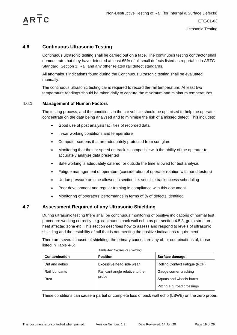
4.7 Assessment Required of any Ultrasonic Shielding
During ultrasonic testing there shall be continuous monitoring of positive indications of normal test
procedure working correctly, e.g. continuous back wall echo as per section 4.5.3, grain structure,
heat affected zone etc. This section describes how to assess and respond to levels of ultrasonic
shielding and the testability of rail that is not meeting the positive indications requirement.
There are several causes of shielding, the primary causes are any of, or combinations of, those
listed in Table 4-6:
Table 4-6: Causes of shielding
Contamination Position Surface damage
Dirt and debris
Rail lubricants
Rust
Excessive head side wear
Rail cant angle relative to the
probe
Rolling Contact Fatigue (RCF)
Gauge corner cracking
Squats and wheels-burns
Pitting e.g. road crossings
These conditions can cause a partial or complete loss of back wall echo (LBWE) on the zero probe.

Non-Destructive Testing of Rail (for Internal & Surface Defects)
ETE-01-03
Ultrasonic Testing
This document is uncontrolled when printed. Version Number: 1.9 Date Reviewed: 14 Jun 20 Page 20 of 29
Levels of shielding severity, actions and response times are given in Table 4-7, for the purposes of
this table:
• LBWE as expected at bolt holes, turnout components etc, shall be disregarded provided
there are no indications of real defects (that are suspected to not be caused by the back-
wall disruption).
• Shielding and untestable rail is to be reported to the relevant ARTC authority and
recorded according to requirements set out in section 0. The reports are to be entered into
the defect database.
The background aims of Table 4-7 are summarised in the following points:
• Due to the differing methods of operation, the requirements for response actions to
shielded rail will also differ for various equipment technologies. High speed running
(generally >40km/h), and automatic defect sizing vehicles, will generally have a slightly
different sequence and time priority of actions to follow, when compared to traditional low
speed (≤40km/h) methods with additional chase cars. This has required the table detailing
initial response to shielding to be split into two main methods.
• The initial aim of the process is to confirm the cause(s) of shielding, and where feasible
and if testability will be improved, require the test car to re-test at low speed if practical.
• If after re-testing, or if retesting by car is not possible, the second aim is to confirm
shielding causes and exact lengths through inspections and hand-testing. Where the
cause of shielding is found to be due to surface damage and/or rail position and side
wear, the risk can usually no longer be addressed through testing actions alone.
• For smaller cases of LBWE the table is aiming to report the early stages of the
deterioration, so remediation can be planned before untestable lengths are reached. Rail
replacement and metal removal processes are required to address LBWE once the
lengths reach too far.
• Finally, where the LBWE is confirmed in a size and condition which masks the true size of
any existing or potential new internal defect(s), apply appropriate risk mitigation.
• All lengths in mm in the table refer to the longitudinal length of LBWE along the rail head.

Non-Destructive Testing of Rail (for Internal & Surface Defects)
ETE-01-03
Ultrasonic Testing
This document is uncontrolled when printed. Version Number: 1.9 Date Reviewed: 14 Jun 20 Page 21 of 29
Table 4-7: Assessment of shielding, response times and actions
1. Shielding Definition
Shielding must be reported when any of the following occurs with car testing at normal speed:
• LBWE greater than 50mm length has been found, OR
• gain had to be turned up, OR
• if the rail is generally difficult to test, OR
• operator suspects that one or more probes are not giving valid results.
2. Contractor Actions (test car)
1. For testing regimes that require manual classification and sizing of defects (typically low speed with a chase car) the test
car is to stop immediately and take actions:
a. Track should be examined to identify cause of loss of detection.
b. Rail should be cleaned if necessary, or car probes adjusted, and re-tested at 5km/h with additional couplant if
necessary.
c. If the rail is still unable to be tested at this stage the test car shall report shielding, specifying the length and
suspected cause within 1 days of testing.
2. For automated testing regimes (typically high speed with no chase car), a detailed report of LBWE lengths shall be
supplied within 1 day of testing, there is no requirement for retesting at slower speeds on shielded locations.
3. ARTC Actions (local team managed)
ARTC Corridor Management for the affected track section shall arrange for the reported shielding cause to be actioned within
the latitude of the relevant ultrasonic testing timeframes or within 7 days of reporting, whichever is the later.
To resolve the shielding issue one of the following actions must be taken to confirm LBWE length:
1. Affected rail locations will be retested either by car or by hand, to determine accurate LBWE lengths, OR
2. LBWE length reported by the contractor is directly used to proceed to the actions listed below.
If a length of LBWE is confirmed in steps 1 or 2 outlined above, the following actions below shall apply;
4. Confirmed LBWE Condition
5. Action
LBWE less than or equal to 50mm No further action
LBWE length greater than 50mm, but
less than or equal to 200mm
The responsible asset engineering authority is to assess the LBWE area reported
and derive a rail rectification strategy to occur within timeframes that prevent the
LBWE growing beyond 200mm length.
Unable to size a defect identified
previously.
Track speed shall be restricted to 40km/h until works are performed to restore
testability (works; rail replacement or grinding/milling metal removal of the shielded
surface depth and successful re-testing).
For any of the following conditions,
• LBWE length greater than 200mm
• more than one LBWE patch
(excluding squats) per metre, with
each patch being between 50 to
200mm in length
• Squatted rail: if there is less than
60mm of testable rail between
squats, thereby preventing the
70° probe from detecting a
transverse defect under either
squat
Track speed shall be restricted to 40km/h until works are performed to restore
testability (works; rail replacement or grinding/milling metal removal of the shielded
surface depth and successful re-testing).
This response action may be varied by a person with CER competency, up to a
maximum track speed restriction of 80km/h, based on documented risk evaluation.
For example (but not limited to), LBWE can be higher risk with;
• boltholes and welds masked
• mudholes/pumping
• passenger, heavy haul or high >50 MGT traffic
• tight curvature <R600m
LBWE cases not greatly affected by high risk factors or conditions may have their
response varied by such CER approved risk evaluations.

Non-Destructive Testing of Rail (for Internal & Surface Defects)
ETE-01-03
Alternative Non-Destructive Testing Techniques
This document is uncontrolled when printed. Version Number: 1.9 Date Reviewed: 14 Jun 20 Page 22 of 29
5 Alternative Non-Destructive Testing Techniques
Alternative Non-Destructive Testing techniques for example dye penetrant testing and magnetic
particle testing are not required to be programmed on a cyclic basis, but can be used as a means
of detecting, confirming or sizing rail cracks with or without ultrasonic testing as required.
Where alternative methods are used, equipment and products should comply with the relevant
Australian Standard. Personnel shall complete specialist training in all NDT Testing techniques
and shall be certified for each technique.
All testing methods and frequencies shall ensure that the broken rail risk profile is not
compromised.

Non-Destructive Testing of Rail (for Internal & Surface Defects)
ETE-01-03
Classifying Defects
This document is uncontrolled when printed. Version Number: 1.9 Date Reviewed: 14 Jun 20 Page 23 of 29
6 Classifying Defects
All rail and weld internal and surface defects, and weld geometry shall be classified in accordance
with ARTC standards.
6.1 Naming System of Defects
Defects which can be identified using non-destructive testing are illustrated in Error! Reference
source not found..
Figure 6-1: Internal rail defects definitions

Non-Destructive Testing of Rail (for Internal & Surface Defects)
ETE-01-03
Classifying Defects
This document is uncontrolled when printed. Version Number: 1.9 Date Reviewed: 14 Jun 20 Page 24 of 29
6.2 Sizing Defects
All indications exceeding 40% of full screen height at evaluation sensitivity shall be measured for
precise size. All defects shall be recorded in mm. See Section 7 for reporting requirements.
All defect sizing should be determined by using the “last significant echo” method. Any loss of back
wall echo or other known reflectors (during hand test sizing) shall be investigated by visual
inspection and scanning from the other faces of the rail.
Figure 6-2: Definition of Defect Dimensions
All indications exceeding 40% of full screen height at evaluation sensitivity shall be evaluated for
size. Sizing should be done by the last significant echo method.

Non-Destructive Testing of Rail (for Internal & Surface Defects)
ETE-01-03
Recording and Reporting Requirements for Rails and Welds
This document is uncontrolled when printed. Version Number: 1.9 Date Reviewed: 14 Jun 20 Page 25 of 29
7 Recording and Reporting Requirements for Rails and Welds
7.1 Format of Reports
Electronic Record keeping is recommended. Where electronic means are used a daily back-up
must be made.
Where paper-based systems are preferred ARTC has published forms that may be used. These
forms are not mandatory; the collection of the information can be done on other forms or in an
electronic spreadsheet. Inspection reports need to contain the reportable data listed in all parts of
this section 7, regardless of the format used.
7.2 Inspection Report
Every ultrasonic test and weld geometry test undertaken shall be recorded. Form ETE0103F-01
Record and Report of Ultrasonic Test may be used. Any defects found should be reported as per
section 7.2.3 below.
A record of every ultrasonic test shall be kept. The report shall be kept even if no defect is found;
or if defect found is small and is not referred to as ‘reportable’ or ‘to be monitored’ in the defect
standards.
7.2.1 Ultrasonic Test Records
The ultrasonic test records may be kept electronically or using paper-based forms such as
ETE0103F-01 Record and Report of Ultrasonic Test, and should record (as a minimum):
• Date
• Location of test
• Name of the operator
• Ultrasonic flaw detector (type, serial No)
• Probes used (type, serial No)
• Couplant used
• Test results
• Any variations from the requirements of this procedure
• Any test restrictions
• Rail temperature:
o At each point where Hand Testing has occurred
o Continuous Car Testing: At least two temperature readings daily to capture the
Maximum and minimum temperature
7.2.2 Weld Test Records
A record of every Weld Test shall be kept electronically or using paper-based forms.
In addition to the requirements of 7.2.1 above, the Weld Test report shall include:
• the weld Number
• date of test

Non-Destructive Testing of Rail (for Internal & Surface Defects)
ETE-01-03
Recording and Reporting Requirements for Rails and Welds
This document is uncontrolled when printed. Version Number: 1.9 Date Reviewed: 14 Jun 20 Page 26 of 29
• location of weld
• result of visual inspection
• result of ultrasonic inspection
• result of geometric inspection.
7.2.3 Defect Reports
All sizeable rail or weld, internal or surface defects, or any weld geometry defect, shall be reported.
Form ETE0103F-02 Rail Flaw Report may be used. This is to provide a record where a defect is
found or if the geometry of a new weld is found to be substandard. This can be on an individual
form, however when the continuous ultrasonic testing is carried out it is more likely to be stored in a
spreadsheet.
In addition to the requirements of 7.2.1 above, the Defect report shall include as a minimum:
• The location of the defect with respect to the kilometrage posts to within ± 5 metres per
1,000m of the last km post encountered or GPS co-ordinates for each defect.
• Each defect is to be allocated an identification number.
• The rail in which the flaw is located, shall be shown. The down rail is the left rail when
facing in the direction of increasing kilometrage. The up rail is the rail opposite the down
rail.
• If in a turnout – the turnout number
• Date of test
• Type of defect
• Size of defect. Additional to the size classification, the actual length of the flaw shall be
indicated
• Any action already applied (e.g. speed restriction, defect plated etc.)
• Where two or more defects are found within one (1) metre of each other, the actual
separating distance of the defects shall be indicated.
Additional requirements where a satellite car is used to perform a detailed assessment:
• In the case of defective welds, the type of weld shall be indicated i.e. Thermit (T), Flash
Butt (FB) or Wire Feed (WF)
• Hand Tests carried out & results
• Rail specification (e.g. rail size, presence of rail wear, SC or HH etc.)
These records will be kept electronically in the relevant Asset Management System.
Note ARTC Rail Defects Handbook gives more detail on the various defect modes.

Non-Destructive Testing of Rail (for Internal & Surface Defects)
ETE-01-03
Recording and Reporting Requirements for Rails and Welds
This document is uncontrolled when printed. Version Number: 1.9 Date Reviewed: 14 Jun 20 Page 27 of 29
7.3 Shielding Reports
Any areas of ultrasonic ‘shielding’ found using the ultrasonic testing car shall be reported. Form
ETE0103F-03 Rail Surface Condition Report may be used. The report may be paper based or
recorded as an electronic database.
The report should record as a minimum:
• Date
• Location of test
• Degree of difficulty in measurement
• Speed of test
• Name of the operator
• Ultrasonic flaw detector (type, serial No.)
• Probes used (type, serial No.)
• Any variations from the requirements of the procedure
• Any test restrictions
• Couplant used
• The following data, which can generally only be collected in the case of a slow speed car
with chase/satellite vehicle
o Suspected reason for shielding (Gauge corner cracking, head checking,
grease etc.)
o Rail temperature
o Any additional tests (at reduced speeds, dye penetrant etc.) and their results.
Note This can be on an individual form, however when the continuous ultrasonic testing is
carried out it is more likely to be stored in a spreadsheet.

Non-Destructive Testing of Rail (for Internal & Surface Defects)
ETE-01-03
Site Marking
This document is uncontrolled when printed. Version Number: 1.9 Date Reviewed: 14 Jun 20 Page 28 of 29
8 Site Marking
8.1 Rail Defect Marking
8.1.1 GPS Coordinates
Paint marking is not mandatory when defect locations are being reported using GPS coordinates.
8.1.2 Paint Marking
Where paint is used to mark rail assessed as requiring remedial action or reassessment the
following paints can be used: Yellow, Orange or colour agreeable to ARTC. The date of
examination and identification code of the ultrasonic operator is also to be marked on the rail.
The paint shall be on the foot, web and side of head, and where possible:
• The defect; type, boundary and remove-by date, could also be marked with white paint
• The defect priority can be marked with paint colours in addition to the yellow marking.
Where defects are classified and sized by hand the defective rail shall be marked for a length of
200mm, showing the location of the defect and its identification number.
8.2 Weld Quality Examination Marking
All new field welds are to be paint marked to identify that they have either passed or failed the weld
quality requirements of ARTC rail and welding standards.
8.2.1.1 Weld Integrity (when visual defect and ultrasonic inspection completed)
All new field welds when ultrasonically tested and checked for visual weld defects, are to be
sprayed with paint on both sides of the rail adjacent to the weld (to assist visual location from either
side of the track). Painting shall be undertaken as follows;
• If the weld quality passes visual and ultrasonic inspections, it shall be painted with one
blue vertical line on the web;
o reaching from foot to head and,
o approximately 100mm away from the weld collar.
o Paint shall not be placed on the weld itself i.e. nowhere on the collar (head, web
and foot), the collar must always be visible and paint-free.
• If the weld is found to contain an internal (ultrasonic) defect or visual defect, or both, it
shall be painted as per 8.1.2 above.
8.2.1.2 Weld Geometry (when rail head geometry inspection completed)
All new field welds, when checked for weld geometry, are to be sprayed with a paint dot on the web
on both sides of the weld area (to allow visual location from either side of the track). Painting shall
be undertaken as follows;
• If the weld quality passes weld geometry inspections, it shall be painted with one blue dot
on the web;
o Dot being roughly 30 to 50mm diameter
o approximately 100mm away from the weld collar

Non-Destructive Testing of Rail (for Internal & Surface Defects)
ETE-01-03
Site Marking
This document is uncontrolled when printed. Version Number: 1.9 Date Reviewed: 14 Jun 20 Page 29 of 29
o Paint shall not be placed on the weld itself i.e. nowhere on the collar (head, web
and foot), the collar must always be visible and paint-free.
• If the weld quality does not pass weld geometry requirements, it shall be painted with one
yellow dot on the web;
A weld that has passed requirements of both 8.2.1.1 and 8.2.1.2. as satisfactory, when looked at
from either side of the track, would appear as one blue vertical line 100mm away from the collar to
one side of the weld, and one blue dot on the web 100mm away from the weld on the opposite side
of the weld.
An example is shown in Figure 8 2: Satisfactory Weld quality – Marking example.
Figure 8-1: Satisfactory Weld quality – Marking example