
Non-clogging Pump DBS 3216.. Pump DBS 3216...30040 TECHNICAL DATA Output: up to 1200 m3/h Delivery...
19
Non-clogging Pump DBS 3216...30040 TECHNICAL DATA Output: up to 1200 m 3 /h Delivery head: up to 100 m Speed: up to 3600 rpm depending of the pump size and material execution Medium temperature: max. 110 °C Casing pressure: 10 bar Shaft sealing: stuffing box or mechanical seal Flange connections: PN 10 Sense of rotation: clockwise, when seen from the drive on the pump APPLICATION Series DBS volute-casing pumps can be used where the requirement is for pumping dirty liquids or liquids with solids. Sewage plants: Storm water, pre-filtered sewage, industrial effluents Chemical plants: Chemical effluents, brines and lies, milk of lime, crystal sludge, filter material, plastic suspensions Rolling mills: Scale-contaminated water from steel and copper rolling mills Foundries and iron Effluents and sludges from dust and and steel works: arrester plants Construction industry: Mixtures of water and cement and water from excavation ditches Paper and cellulose Paper, chemical pulp and mechanical pulp industry: suspensions up to 6% absolutely dry Sugar mills: Carbonation juice, concentrated juice, milk of lime Food industry: Thick mash, fruit and potato slices (parings) DESIGN Process type, single-stage, volute casing pumps with design features and nominal rating to ISO2858/EN22858 and enlarged sizes The process design permits dismantling of the complete bearing unit towards the drive end, without the pump casing having to be disconnected from the piping. If a spacer coupling is used it is also unnecessary to disconnect the motor. CONSTRUCTION Casing pressure: Max. 10 bar between -10 º C and +120 º C Please note: Casing pressure = Inlet pressure + shut off head. Max. test pressure 16 bar Branch positions: Suction branch axial, discharge branch radial upwards. Flanges: Connection dimensions of flanges DIN 2501 PN 10 . Flanges can be supplied drilled to ANSI Optional the pump can be supplied with a flange adapter piece on the suction side (see sectional drawing, pos. 72.20) Bearings: Execution B: Pump end: one cylindrical roller bearing to DIN 5412 Drive end: one deep groove ball bearing to DIN 625 The bearings are grease lubricated Execution C: Pump end: one cylindrical roller bearing to DIN 5412 Drive end: one deep groove ball bearing to DIN 625 The bearings are oil lubricated Execution S: Pump end: one cylindrical roller bearing to DIN 5412 Drive end: two angular contact ball bearings in O- arrangement. The bearings are grease lubricated Execution T: Pump end: one cylindrical roller bearing to DIN 5412 Drive end: two angular contact ball bearings in O- arrangement. The bearings are oil lubricated Shapes of impellers: Double channel impeller (code Z) or triple channel impeller (code D) Free-flow impeller (code F) If required, the sealing clearance gap on the suction side of pumps fitted with double and triple channel and wear plates can be arranged for flushing.
Transcript of Non-clogging Pump DBS 3216.. Pump DBS 3216...30040 TECHNICAL DATA Output: up to 1200 m3/h Delivery...

Non-clogging Pump
DBS 3216...30040 TECHNICAL DATA Output: up to 1200 m3/h Delivery head: up to 100 m
Speed: up to 3600 rpm depending of the pump size and material execution
Medium temperature: max. 110 °C
Casing pressure: 10 bar Shaft sealing: stuffing box or mechanical seal
Flange connections: PN 10 Sense of rotation: clockwise, when seen from the drive on the pump
APPLICATION
Series DBS volute-casing pumps can be used where the requirement is for pumping dirty liquids or liquids with solids. Sewage plants: Storm water, pre-filtered sewage,
industrial effluents
Chemical plants: Chemical effluents, brines and lies, milk of lime, crystal sludge, filter material, plastic suspensions
Rolling mills: Scale-contaminated water from steel and copper rolling mills
Foundries and iron Effluents and sludges from dust and and steel works: arrester plants
Construction industry: Mixtures of water and cement and water from excavation ditches
Paper and cellulose Paper, chemical pulp and mechanical pulp industry: suspensions up to 6% absolutely dry
Sugar mills: Carbonation juice, concentrated juice, milk of lime
Food industry: Thick mash, fruit and potato slices (parings)
DESIGN
Process type, single-stage, volute casing pumps with design features and nominal rating to ISO2858/EN22858 and enlarged sizes
The process design permits dismantling of the complete bearing unit towards the drive end, without the pump casing having to be disconnected from the piping. If a spacer coupling is used it is also unnecessary to disconnect the motor.
CONSTRUCTION
Casing pressure: Max. 10 bar between -10 º C and +120 º C Please note: Casing pressure = Inlet pressure + shut off head. Max. test pressure 16 bar Branch positions: Suction branch axial, discharge branch radial upwards.
Flanges: Connection dimensions of flanges DIN 2501 PN 10 . Flanges can be supplied drilled to ANSI Optional the pump can be supplied with a flange adapter piece on the suction side (see sectional drawing, pos. 72.20)
Bearings:
Execution B: Pump end: one cylindrical roller bearing to DIN 5412 Drive end: one deep groove ball bearing to DIN 625 The bearings are grease lubricated
Execution C: Pump end: one cylindrical roller bearing to DIN 5412 Drive end: one deep groove ball bearing to DIN 625 The bearings are oil lubricated
Execution S: Pump end: one cylindrical roller bearing to DIN 5412 Drive end: two angular contact ball bearings in O-arrangement. The bearings are grease lubricated
Execution T: Pump end: one cylindrical roller bearing to DIN 5412 Drive end: two angular contact ball bearings in O-arrangement. The bearings are oil lubricated
Shapes of impellers:
Double channel impeller (code Z) or triple channel impeller (code D) Free-flow impeller (code F)
If required, the sealing clearance gap on the suction side of pumps fitted with double and triple channel and wear plates can be arranged for flushing.

Shaft sealing: A stuffing box or a mechanical seal, as required, can affect the sealing of the shaft. Variants with stuffing box: Designation 052: Uncooled stuffing box with external sealing
(inlet only). Temperature range: -10 º C to 110º C.
Designation 051: Uncooled stuffing box with external sealing and flushing Temperature range: -10º C to 110º C.
Designation 071: Uncooled stuffing box with flushing upstream of packing and flushing between wear plate and impeller (only for double and twin channel impellers) Temperature range: -10º C to 110 º C
Variants with mechanical seal: The installation with mechanical seal to DIN 24960 is possible in all versions described there, as a single mechanical seal, double mechanical seal and mechanical seal with a stationary spring element. Double mechanical seals can be mounted in back-to-back or tandem arrangement. Designation BKW: Unbalanced mechanical seal,
Materials: SiC-SiC- Perbunan Temperature range: -20…+ 120 º C
Designation BKS: Unbalanced mechanical seal
Materials: SiC-SiC-Viton Temperature range: -20…+ 120 º C
Other shaft seals upon request.
MATERIAL EXECUTION:
Material execution Pos. ITEMS
0B 0E 4B 10.20 Casing Cast iron 13.50 Wear plate Cast
iron Stainless steel
16.10 Casing cover Cast iron 21.10 Shaft Carbon steel 23.00 Impeller Cast
iron Stainless steel
Stainless steel
33.00 Bearing bracket Cast iron 52.30 Shaft sleeve mechanical seal 52.40 Shaft sleeve stuffing box
Stainless steel
Other materials on request Casing seal: The casing is sealed by flat gasket IT 400.
Drive / Speed: By commercial electric motors, type of construction motor, IM B3.
For the determination of the drive power we recommend the following additions:
Up to 4 kW: 25% 4 up to 7,5 kW: 20% from 7,5 kW: 15%
The following speeds limits are to be observed:
Max. Speed rpm Size Max. speed rpm Size Max. speed rpm Size Max. speed rpm Size
1500 12550D 20050D 3600
3216F 3220F
4016F/D 4020F/D 5016F/D 5020F/Z 6520F/Z
3000 5026F/D 8026F/Z 10026F/Z
1800
5032F/Z 8032F/Z 8040Z
10032F/D 12540F/D 15032Z 20032D 20040D
960 30040D
The max. speed result from the admissible shaft load and the admissible peripheral speed of the impellers
Maximum permissible shaft load (rpm)inn
(kW)inNP
Shaft Carbon steel Stainless steel Shaft Carbon steel Stainless steel
35 45 55
0,011 0,022 0,052
0,008 0,016 0,040
65 75
0,10 0,18
0,08 0,14
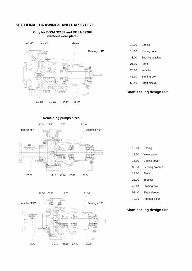
SECTIONAL DRAWINGS AND PARTS LIST
Shaft sealing design 052
Shaft sealing design 052
Only for DBSA 3216F and DBSA 3220F (without wear plate)
21.1010.2023.00
16.10 52.4046.10 33.00
Remaining pumps sizes
21.1010.2023.0013.50
16.10 52.4046.10 33.0072.20
72.20 33.0046.10 52.4016.10
13.50 23.00 10.20 21.10
10.20 Casing
16.10 Casing cover
33.00 Bearing bracket
21.10 Shaft
23.00 Impeller
46.10 Stuffing box
52.40 Shaft sleeve
Bearings: “B”
Impeller “F” Bearings: “S”
Impeller “Z/D” Bearings: “S”
10.20 Casing
13.50 Wear plate
16.10 Casing cover
33.00 Bearing bracket
21.10 Shaft
23.00 Impeller
46.10 Stuffing box
52.40 Shaft sleeve
72.20 Adapter piece

Types of shaft sealings
Designation 051: Uncooled stuffing box with external sealing and flushing. Temperature range: -10º C to 110º C
Designation 071: Uncooled stuffing box with flushing upstream of packing and flushing between wear plate and impeller. Temperature range: -10º C to 110º C
Mechanical seal
PERFORMANCE GRAPHS
Pumps with free flow impeller “F” 1450 rpm
2900 rpm

Pumps with channel impeller, double (Z) respectively triple (D)
2900 rpm
1450 rpm
960 rpm

DIMENSIONS
Dimensions in mm
Pumps dimensions Foot dimensions Shaft end Spa 1) Size Bearing
DN2 DN1 a f h1 h2 b c c1 e1 m1 m2 n1 n2 s s1 w d l t u y o P
3216 425 132 160 15 315
3220 35 32 50 80
420 160 180 310
4016 405 180 295
- -
4020 35 40 50 90
410 160
200
240 190
300
5016 35 100 405 160 295
28 60 31 8
5020 112 180 200
50 6 100 70
265 212
13
5026 45
65
125 500
200 250 8 320 250 15 38 80 41 10
5032 55
50
140 550 225 280 12 345 280 14 48 110 51.5 14
6520 45 65 80
125 500 180 225
65
14
6
125 95
320 250
14
13 38 80 41 10
80 200
8026 130 225 280
8032 55 100
125 550
250 315 12
110
400 315 14
370
48 51.5 14
8040 65
80
670 280 355 15 140 435 355 18 500 55 59 16
10026 225 280
10032 55 100
125 140 550
250 315
80 18
12 110
160 120
400 315
18
14 370 48 51.5 14
140
125 250
12540 65 670 315 400 500 400 55
110
59 16
12550 75 125
720 355 450 550 450 65 140 69 18
15032 150
150 170
280 400 500 400
280
20032 65 670
315 450 55 110 59 16
20040 355 500
22 15
550 450
20050 75
200 200 200 720
400 530
100
24 15
140 200 150
600 500
22 18 500
65 140 69 18
180 150
300
30040 Dimensions on request
Dimensions connections flanges according to DIN 2501 PN - 10
DN1/DN2 32 40 50 65 80 100 125 150 200 Ø D 140 150 165 185 200 220 250 285 340 Ø k 100 110 125 145 160 180 210 240 295
d1 x number - -
*) 18 x 4 M 16 x 4 *) 18 x 4
M 16 x 4 M 16 x 8 M 16 x 8 M 16 x 8 M 20 x 8 M 20 x 8
d2 x number 18 x 4 18 x 4 18 x 4 18 x 4 18 x 8 18 x 8 18 x 8 22 x 8 22 x 8 *) Only for sizes 32…

TABLE OF CONNECTIONS
For version with Code Connections
Grease Oil
I Pressure gauge connection II Pressure/vacuum gauge connection III Vent VII Drain IX Drip and leakage connection Xa Inlet connection for sealing liquid External sealing Xb Outlet connection for sealing liquid External sealing
XV Oil filling X XVI Oil drain X
XVIIa Oil level sight glass X XVIIb Constant level oiler connection X
XX Grease nipple X XXIIIa Flushing liquid connexion for shaft seal Flushing before packing XXIIIb Flushing liquid connexion for wear plate Flushing of wear plate XXIIIc Seal flushing External sealing
Dimensions of connections
Pumps with shaft unit 35 45 55 65 75 90 Code
Standard type
Special type
Standard type
Special type
Standard type
Special type
Standard type
Special type
Standard type
Special type
I G 1/2” (4) G 1/2” G 1/2” G 1/2” G 1/2”
II Without
hole G 1/2”
Without hole
G 1/2” Without
hole G 1/2”
Without hole
G 1/2” Without
hole G 1/2”
III G 1/2” (5) G 1/2” G3/4” G 1” (3) G 1” VII G 1/2” (6) G 1/2” (1) G 1” (2) G 1” (3) G 1” IX G 1/2” G 1/2” G 1/2” G 3/4” G 3/4” Xa G 1/4” G 1/4” G 1/4” G 3/8” G 3/8” Xb G 1/4” G 1/4” G 1/4” G 3/8” G 3/8”
XV Ø 20 Ø 20 Ø 20 Ø 20 Ø 20 XVI G 1/4” G 1/4” G 1/4” G 1/4” G 1/4”
XVIIa G 3/4” G 3/4” G 3/4” G 3/4” G 1” XVIIb G 1/4” G 1/4” G 1/4” G 1/4” G 1/4” XX M6 M6 M6 M6 M6
XXIIIa G 1/4” G 1/4” G 1/4” G 3/8” G 3/8” XXIIIb G 1/2” G 1/2” G 1/2” G 1/2” G 1/2” XXIIIc G 3/8” G 1/2” G 1/2” G 1/2” G 1/2”
On
requ
est
1) G 3/4” in 6520 2) G 3/4” in 5032, 8026 and 8032 3) G 3/4” in 8040 4) G 1/4” in 3216 and 3220 5) Pumps 3216, 3220 not drilled 6) G 1/4” in 3216 and 3220

Foundation Plan
n=2900 rpm

Foundation Plan n=2900 rpm

Foundation Plan
n=1450 rpm
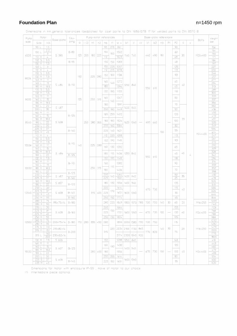
Foundation Plan n=1450 rpm

Foundation Plan n=1450 rpm
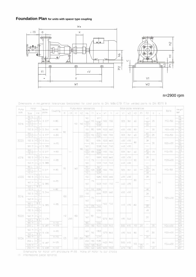
Foundation Plan for units with spacer type coupling
n=2900 rpm
Foundation Plan for units with spacer type coupling n=2900 rpm

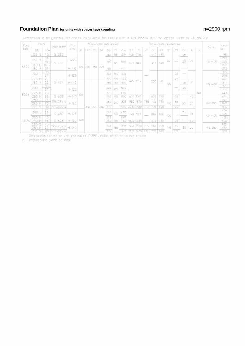
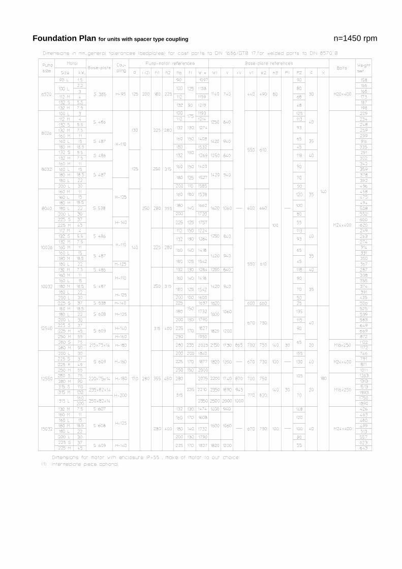
Foundation Plan for units with spacer type coupling
n=1450 rpm
Foundation Plan for units with spacer type coupling n=1450 rpm

Foundation Plan for units with spacer type coupling n=1450 rpm

Product identification
Series + sizes
Impeller type
Hydraulic
Bearing
Shaft
sealing
Material
Casing design
D triple channel impeller
Z double channel impeller
F free-flow impeller
A
B: Pump end: one cylindrical roller bearing to DIN 5412 Drive end: one deep groove ball bearing to DIN 625 grease lubrication
C: Pump end: one cylindrical roller bearing to DIN 5412 Drive end: one deep groove ball bearing to DIN 625 oil lubrication
S: Pump end: one cylindrical roller bearing to DIN 5412 Drive end: two angular contact ball bearings in O-arrangement. grease lubrication
T: Pump end: one cylindrical roller bearing to DIN 5412 Drive end: two angular contact ball bearings in O-arrangement. oil lubrication
051* 052 071 BKS BKW
0B main parts of cast iron
0E main part of cast iron, but impeller, wear plate of stainless steel
4B main parts of stainless steel
B with wear plate
C without wear plate
DBSA 03216
03220 F C
04016
04020
05016 D/F
B, C
05020 Z/F
05026 D/F
05032
06520
08026
08032
Z/F
08040 Z 10026 Z/F 10032 12540
D/F
12550 D 15032 Z 20032 20040 20050 30040
D
A
S, T
Alternativ 051 052
071** BKS BKW
Alternativ 0B 0E 4B
B
* see page 2 under shaft sealing ** not valid for sizes 3216 and 3220
If we are informed of the motor type being selected, the coupling can be supplied already drilled on motor side and we can supply the coupling guard and the shims for equalizing out the centre height.
Any changes in the interest of the technical development are reserved.