Non-cartesian CNC CMM · Xtreme CNC CMM provides a robust solution for providing precision...
13
Product Catalogue
Transcript of Non-cartesian CNC CMM · Xtreme CNC CMM provides a robust solution for providing precision...

Product Catalogue

Aberlink Ltd is the largest UK-owned manufacturer of coordinate measuring machines, vision measuring systems and measurement software.
From our headquarters in Eastcombe, Gloucestershire, England we are engaged in every aspect of providing industry with innovative metrology products that are reliable, cost effective and above all easy to use. Through our distributor network in over 40 countries worldwide we provide all sectors of manufacturing with world class sales and aftercare service.
Incorporated in 1993 and now celebrating 25 years of innovative metrology, Aberlink has an impressive record of growth founded on innovation. This has been the background for all our patented product development, with the tagline ‘Innovative Metrology’ firmly at the heart of company philosophy.
Aberlink always view things from a customer perspective and our revolutionary Aberlink 3D measurement software has become the industry standard for ease of use. It is not only intuitive and simple to learn, but also extremely powerful and is ideal for either the occasional user or metrology professional alike.
Our products and services provide customers with remarkable value for money. This has been achieved by producing a fully self-contained business model from day one. Because we machine all the components for the machines ourselves, we understand the manufacturing process fully, and clever design-for-manufacture ensures simple and reliable products with no redundant costs. All assembly of the machines is performed on-site in Gloucestershire, where the software is also written in-house. We are a fully integrated company with minimal external costs and that is why we are able to offer the amazing value for which Aberlink has become renowned throughout the world.
You really need to see our products demonstrated to appreciate just how easy they are to use. Visit our website www.aberlink.com to find your local demonstration facility.
Xtreme 4Non-cartesian CNC CMM
Axiom too 6Manual or CNC Shop Floor CMM
Axiom too HS 8High Spec CNC Shop Floor CMM
Zenith 3 10Medium-sized Shop Floor CNC CMM
Azimuth 12High Accuracy, Large Volume CNC CMM
Probe Options 14Common Probe and Probe Head Options
Aberlink 3D 16Revolutionary 3D Measurement Software
CAD Software Modules 18CAD Comparison and Programming from CAD
Camera and Vision Module 20Non-contact Inspection
Project X 21Advanced Non-contact Vision System
Accessories 22CMM Accessories and Machine Options
Creating Innovative Metrology Solutions
Reliable, Intel l igent, AffordableMeasurements for manufactur ing
CO
NTE
NTS
www.aberlink.com

4 5
Key Features:
Machine Options:
XY
Z
www.aberlink.com
Designed using a non-Cartesian structure and utilising linear motors and mechanical bearings, as its name implies, the Xtreme CNC CMM provides a robust solution for providing precision inspection results. The unique CMM’s advantageous configuration ensures that it maintains its accuracy at very fast measurement rates and does not suffer from the accumulative inaccuracies that occur in conventional 3-axis Cartesian designs. Available in two sizes, the Xtreme is a self-contained inspection unit. It has no air bearings, so no requirement for compressed air – just plug it in and go. Built-in temperature control and a compact footprint allow the Xtreme to be placed wherever it is needed. Another unique advantage of the Xtreme is that all of the struts are temperature controlled to operate above ambient air temperature. This means that the measurement accuracy is maintained even when the surrounding environment is not temperature controlled. The Xtreme can be supplied with either a 22” LED monitor side-mounted on an ergonomic arm or, a touch-screen monitor mounted at head height on the front panel of the machine.
XTREMECMM ACCURACY WHEREVER YOU NEED IT
Xtreme Non-cartesian CNC CMM
• Ergonomic monitor arm or touch-screen monitor• Probe change rack and TP20 probe module• Industrial Joystick• Fixture Kit
• No compressed air required - the Xtreme is ‘plug and go’
• Built-in temperature control - accuracy is maintained even when ambient temperature is not controlled
• Aberlink’s revolutionary easy-to-use measurement software
• Shortest learning curve of any equivalent system - 1 day without prior CMM experience
• Smallest overall footprint of any comparable size CMM
• The Xtreme’s mechanical bearings mean that it is robust, so ideal for less than perfect environments
• Free software upgrades - no maintenance fees or contracts
Technical Information:Robust design utilising linear motors and mechanical bearings.
Model: 350 500
Axis Travel (mm) Min Linear Circular
X 300Y 300Z 200 200
Min Linear Circular
X 400Y 400Z 270 270
Overall Size (mm) X 790Y 900Z 2030
X 905Y 1140Z 2195
Overall Size (mm)with monitor arm
X 995Y 1060Z 2030
X 1120Y 1300Z 2195
Volumetric Accuracy: (3 + 0.4L/100) µm (3 + 0.4L/100) µm
Scale Resolution: 0.5µm 0.5µm
Operational Temp Range: 0 - 45°C 0 - 45°C
Table: Granite plate Granite Plate
Max. Velocity Vector: 500mm/sec 500mm/sec
Max. Acceleration Vector: 750mm/sec² 750mm/sec²
Air Consumption: None None
Required Air Pressure: Not required Not required
Ø359 Ø510} }

6 7
Key Features:
Common Probe Options: Machine Options:
Y X
Z
www.aberlink.com
Axiom too
Fast, accurate and reliable, the Axiom too CMM comes in four different sizes with Y axis travel up to 1500mm. Available as either a manual machine or with full CNC control, the Axiom too can be used with touch trigger probe, continuous contact scanning probe or with Aberlink’s revolutionary non-contact camera system. The all aluminium bridge structure not only ensures that the Axiom too has low inertia and hence high acceleration to get the job done quickly, but also that the temperature of the machine rapidly follows the temperature of the room, ideal when the CMM is not housed in a controlled environment. Temperature compensation in the software reports results as if they had been measured at 20°C/68°F. The standard high-tech granite and aluminium table, originally developed for the optics industry, provides fantastic natural damping of high frequency vibration and the granite Y rail allows pre-loading of the bridge air bearings in both directions for superior accuracy. Another unique feature of the Axiom too is that manual machines can be easily upgraded to CNC at any point in the future, which is great if you are not sure of your requirement or perhaps can’t initially justify the additional cost of a CNC machine. Because of Aberlink’s fully integrated manufacturing processes, the Axiom too offers unbelievable value, but above all it is easy to use.
AXIOM TOO THE COMPLETE INSPECTION SYSTEM
Manual or CNC Shop Floor CMM
*Maximum Permissible Error MPEE according to 10360-2, 2009 within the thermal limits defined for optimum temperature range.
**Installation environment thermal limits: Rate of change <1°C/hr and <2°C/24hr | Temperature gradient <1°C/m
†Dual monitor arm optional extra
• MH20i• RTP20• PH10T (w/TP20, TP200)• PH20• PH10M (w/SP25)• PH6M (w/SP25)
• Auto Temperature Compensation• Touch Screen Joystick• Industrial Joystick• CCD Camera System• Collimated Back Light Option• Dual Monitor• Fixture Kit
• Shortest learning curve of any equivalent system
• Smallest overall footprint of any comparable size CMM
• Choice of Y axis sizes ranging from 600mm to 1500mm
• Suitable for the workshop environment
• Protection from environmental vibrations as standard
• Optimised friction free air bearings, aluminium bridge and granite table
• Free software upgrades - no maintenance fees or contracts
Axis Travel (mm) X 640Y 600, 900, 1200, 1500Z 500
Overall Size (mm) X 1130Y 900, 1200, 1500, 1800Z 2320
*Volumetric Accuracy: TP20 (2.4 + 0.4L/100) µmTP200 (2.3 + 0.4L/100) µmSP25M (2.1 + 0.4L/100) µm
Scale Resolution: 0.5µm
**Optimum Temp Range: 18 - 22°C
Operational Temp Range: 0 - 45°C
Table: Honeycomb aluminium & granite or solid granite
Table Load Capacity: 300kg (Honeycomb) or 500kg (Solid)
Max. Velocity Vector: 600mm/sec
Max. Acceleration Vector: 600mm/sec²
Air Consumption: 50 l/min (1.8 cfm)
Required Air Pressure: 4 bar (60 psi)
Technical Information:Available with solid granite table.

8 9Axiom too HS High Spec CNC Shop Floor CMM
Key Features:
Common Probe Options: Machine Options:
Y X
Z
www.aberlink.com
0.1µm resolution scales fitted as standard.
Since 2004 the Axiom too CMM has been providing manufacturing industry with a fast and accurate solution for their measurement problems. But, as ever, Aberlink are continually striving to improve the solutions which they offer. The Axiom too HS is both faster and more accurate than the standard model, and all without compromising the fantastic value for money for which Aberlink have become renowned. Rather than using the belt drive system, the Axiom too HS incorporates drive rod technology developed on our larger machines and vision products. This allows even greater accelerations to be achieved meaning that the HS model measures approximately 20% quicker than the standard variant – ideal for high volume measurement. The Axiom too HS also utilises 0.1µm resolution scales on each axis. Incorporated with state-of-the-art error mapping techniques this means that the HS model is the most accurate machine ever produced by Aberlink – ideal when measuring tight tolerances.
AXIOM TOO HSELIMINATE INSPECTION BOTTLENECKS
*Maximum Permissible Error MPEE according to 10360-2, 2009 within the thermal limits defined for optimum temperature range.
**Installation environment thermal limits: Rate of change <1°C/hr and <2°C/24hr | Temperature gradient <1°C/m
• MH20i• RTP20• PH10T (w/TP20, TP200)• PH20• PH10M (w/SP25)• PH6M (w/SP25)
• Auto Temperature Compensation• Touch Screen Joystick• Industrial Joystick• CCD Camera System• Collimated Back Light Option• Dual Monitor• Fixture Kit
• Fitted with 0.0001mm linear encoders for superior accuracy
• Angled bearing zero backlash drive system for quicker acceleration and faster travel
• Shortest learning curve of any equivalent system
• Choice of Y axis sizes ranging from 600mm to 1500mm
• Suitable for the workshop environment
• Protection from environmental vibrations as standard
• Optimised friction free air bearings, aluminium bridge and granite table
• Free software upgrades - no maintenance fees or contracts
Axis Travel (mm) X 640Y 600, 900, 1200, 1500Z 500
Overall Size (mm) X 1130Y 900, 1200, 1500, 1800Z 2320
*Volumetric Accuracy: TP20 (2.1 + 0.4L/100) µmTP200 (2.0 + 0.4L/100) µmSP25M (1.8 + 0.4L/100) µm
Scale Resolution: 0.1µm
**Optimum Temp Range: 18 - 22°C
Operational Temp Range: 0 - 45°C
Table: Honeycomb aluminium & granite or solid granite
Table Load Capacity: 300kg (Honeycomb) or 500kg (Solid)
Max. Velocity Vector: 866mm/sec
Max. Acceleration Vector: 1200mm/sec²
Air Consumption: 50 l/min (1.8 cfm)
Required Air Pressure: 4 bar (60 psi)
Technical Information:

10 11Zenith 3 High Speed, Medium-sized CNC CMM
Key Features:
Common Probe Options: Machine Options:
Y X
Z
www.aberlink.com
• Shortest learning curve of any equivalent system
• Smallest overall footprint of any comparable size CMM
• Choice of Y axis sizes ranging from 1000mm to 3000mm
• Suitable for the workshop environment
• Optimised friction free air bearings, aluminium bridge and granite table
• Supplied with the CMM touch screen joystick as standard
• Free software upgrades - no maintenance fees or contracts
Redesigned right leg for improved stiffness and accuracy.
The Zenith 3 CNC CMM is the result of a design evolution of the award winning Zenith too range of machines. Many of the design improvements revolve around the right leg of the machine, which has been modelled on the hugely successful Azimuth machine.
Greater air bearing separation results in greater stiffness, and so has improved the accuracy significantly. The first term error for this new model is more than a micron better than the Zenith too. All moving parts are light and this, combined with good design, means that the Zenith 3 has low inertia and therefore optimal acceleration characteristics. The improved Zenith is fast, minimising inspection times.
The Zenith 3 range is the best value-for-money for the measuring volume of any CMM available in the market - the perfect affordable metrology solution for big and heavy parts.
ZENITH 3 LARGE, AFFORDABLE PRECISION
*Maximum Permissible Error MPEE according to 10360-2, 2009 within the thermal limits defined for optimum temperature range.
**Installation environment thermal limits: Rate of change <1°C/hr and <2°C/24hr | Temperature gradient <1°C/m
• RTP20• PH10T (w/TP20, TP200)• PH20• PH10M (w/SP25)• PH6M (w/SP25)
• 4400Kg load capacity• Auto Temperature Compensation• CCD Camera System• Collimated Back Light Option• Dual Monitor• Fixture Kit
Axis Travel (mm) X 1000Y 1000, 1500, 2000, 2500, 3000Z 600, 800
Overall Size (mm) X 1520Y 1700, 2200, 2700, 3200, 3700Z 2500, 2900
*Volumetric Accuracy: TP20 (2.7 + 0.4L/100) µmTP200 (2.6 + 0.4L/100) µmSP25M (2.4 + 0.4L/100) µm
Scale Resolution: 0.5µm
**Optimum Temp Range: 18 - 22°C
Operational Temp Range: 0 - 45°C
Table: Granite
Table Load Capacity: 1500kg as standard. Options up to 4400kg
Max. Velocity Vector: 600mm/sec
Max. Acceleration Vector: 600mm/sec²
Air Consumption: 50 l/min (1.8 cfm)
Required Air Pressure: 4 bar (60 psi)
Technical Information:

12 13
Key Features:
Machine Options:Common Probe Options:
X
Z
Y
www.aberlink.com
State of the art design ensures maximum stiffness for both greater speed and higher accuracy.
As CMMs get larger, it is not simply a case of scaling up the design of smaller models. Stiffness of the structure is critical, but weight must also be kept to a minimum. The Azimuth CMM is not only Aberlink’s largest in their range of CMM products, but it is the culmination of over twenty-five years experience and excellence in the design and manufacture of innovative metrology equipment incorporating the very latest materials technology. The revolutionary bridge of the Azimuth incorporates aluminium honeycomb sheets developed for use in formula one and the aerospace industry. The remarkable stiffness to weight ratio that this provides gives the Azimuth an edge in both performance and speed. For a machine of this size, the Azimuth is not only fast, but extremely accurate. The drive systems designed for the Azimuth offer simplicity and reliability and the novel system used on the Y axis ensures that there is no degradation of performance across the full range of machine sizes offered up to 3m. A big machine should also be able to measure a heavy component and this is another area where Aberlink has applied innovative thinking. Rather than simply increasing the depth of the granite table, which adds huge cost and weight to the machine, we offer a specially designed load plate to sit on the granite base. This plate can accept up to a six tonne load which will then be transmitted directly through the feet of the machine bench directly to the floor, meaning no loss of metrology performance.
AZIMUTH FROM STRENGTH TO STRENGTH
*Maximum Permissible Error MPEE according to 10360-2, 2009 within the thermal limits defined for optimum temperature range.
**Installation environment thermal limits: Rate of change <1°C/hr and <2°C/24hr | Temperature gradient <1°C/m
Azimuth Rapid, High Accuracy Large Volume CMM
• Capable of measuring parts up to 6000kg in weight
• Fitted with 0.0001mm linear encoders for superior accuracy
• Unique self-contained drive system ensures excellent performance over the entire measuring volume
• Choice of Y axis sizes ranging from 1000mm to 3000mm
• Supplied with the CMM touch screen joystick as standard
• Free software upgrades - no maintenance fees or contracts
• PH10T (w/TP20, TP200)• PH20• PH10M (w/SP25)• PH6M (w/SP25)
• Load plate for loads up to 6 tonnes• Auto Temperature Compensation• CCD Camera System• Collimated Back Light Option• Dual Monitor• Fixture Kit
Axis Travel (mm) X 1200Y 1000, 1500, 2000, 2500, 3000Z 1000
Overall Size (mm) X 1940Y 2000, 2500, 3000, 3500, 4000Z 3595
*Volumetric Accuracy: TP20 (2.9 + 0.4L/100) µmTP200 (2.8 + 0.4L/100) µmSP25M (2.6 + 0.4L/100) µm
Scale Resolution: 0.1µm
**Optimum Temp Range: 18 - 22°C
Operational Temp Range: 0 - 45°C
Table: Granite
Table Load Capacity: 1500kg as standard. Options up to 6000kg
Max. Velocity Vector: 650mm/sec
Max. Acceleration Vector: 850mm/sec²
Air Consumption: 50 l/min (1.8 cfm)
Required Air Pressure: 4 bar (60 psi)
Technical Information:

1514
www.aberlink.com
TP8 Probe
The TP8 probe offers an entry level option for customers that require infrequent indexing of the probe and no indexing during the running of a measurement programme. The TP8 is supplied with two knuckle joints to allow infinite alignment of the probe to the feature being measured, but this alignment is non-repeatable, meaning that the stylus will need to be requalified following each index. The TP8 probe accepts the M3 range of styli.
MH20i Probe Head
The MH20i probe offers repeatable manual indexing of the probe head from 0° to 90° in the A axis and through
360° in the B axis, in 15° increments. Ideal for manual CMMs, it can also be used on CNC models, but will require
intervention from the operator whenever indexing is required. The MH20i uses a TP20 stylus module, which in
turn accepts the M2 range of styli.
RTP20 Probe Head
The RTP20 probe offers a really cost effective solution for customers that require automatic indexing on CNC machines. Modelled on the MH20i body, the RTP20 uses the CNC motion of the CMM to position itself using a post mounted to the bed of the machine. Like the MH20i it is able to index from 0° to 90° in the A axis and through 360° in the B axis, in 15° increments and uses a TP20 stylus module, which in turn accepts the M2 range of styli. The RTP20 is also fully compatible with the MCR20 change rack to provide an option that provides both automatic stylus changing as well as automatic indexing.
PH10T Probe Head
The PH10T is a fully motorised probe head that offers immediate indexing from 0° to 105° in the A axis and through 360° in the
B axis, in 7.5° increments. This probe head should be used by customers requiring frequent indexing or when more precise
alignment to the features being measured is required.
Common probe options for the PH10T:
TP20
The TP20 is a robust probe for general purpose measurement that can be
used in conjunction with the MCR20 change rack to
facilitate automatic stylus changing. The TP20 stylus
modules can be supplied with different trigger forces which accept M2 styli up to 60mm
long, and with different length modules to assist with probing
at greater depths.
TP200
The TP200 probe utilises strain gauge technology and
so does not exhibit lobing characteristics and therefore
should be considered by customers requiring more
accurate measurement of form. It can be used with the SCR200
change rack for automatic stylus changing and the TP200
modules are available as standard or low force for use
with M2 styli up to 100mm long.
PH10T probe head fitted with TP20
probe
PH10M Probe Head
Like the PH10T probe head, the PH10M is also a fully motorised probe head that offer immediate indexing from 0° to 105° in the A axis and through 360° in the B axis, in 7.5° increments. The M head, however, incorporates an autojoint with multiwire capability, which is necessary for the SP25M scanning probe. The PH10M probe head can also be fitted with either TP20 or TP200 probes and should be chosen in preference to the PH10T when using these probes if the future use of a scanning technology may be required.
PH6M Probe Head
This head provides a fixed autojoint for when an SP25M
scanning probe is needed without the requirement for
indexing.
SP25M Scanning Probe
The SP25M scanning probe uses an isolated optical metrology transducer system to enable extremely accurate measurements to be taken with the stylus in continuous
contact with the feature being inspected. This enables more data to be taken which is important when form is critical. A range of modules are available for the SP25M to
provide optimised scanning performance using M3 styli up to 400mm long.
PH20 Probe Head
Incorporating the latest 5-axis technology, the PH20 head offers infinite indexing to assist with alignment to any feature being measured at any angle up to 120°. The probe is able to perform ‘head touches’, where it flicks the stylus on to the surface of the component being measured, while the machine remains stationary. This increases both the speed of measuring and accuracy achievable. Please note that if selecting the PH20 head, then the machine would also have to be fitted with a Renishaw CMM controller. The PH20 uses TP20 stylus modules, which in turn accept the M2 range of styli.
Integral Probe
IndexMotion
MaximumLength
IndexResolution
IndexPositions
Repeatable Indexing
Repeatable Stylus Changing
TP8Yes Manual 105mm Infinite Infinite No No
MH20iYes Manual 150mm 15° 168 Yes Yes
RTP20Yes Automated 168mm 15° 168 Yes Yes
PH10TNo Motorised 450mm 7.5° 720 Yes Yes
PH20Yes Motorised 168mm Infinite Inifinite Yes Yes
PH6MNo No 450mm No No No Yes
PH10MNo Motorised 450mm 7.5° 720 Yes Yes
Probe Head Comparison
PH10M with SP25M scanning probe
PH6M with SP25M scanning probe
Probe Options Probes & Probe Heads
Every bridge-type Aberlink CMM fully supports the range of probe heads and both touch trigger and scanning probes supplied by Renishaw. The following are common options:

1716
www.aberlink.com
The whole philosophy for Aberlink is to make measurement easy. Aberlink 3D software has been written by engineers for engineers and sets the industry standard for simple-to-use software. Designed around a graphical interface, Aberlink 3D can work in 2D or 3D, on manual or CNC CMMs and is equally at home when used with either touch, scanning or vision systems. It is easy to understand why Aberlink 3D has become the software of choice not only for Aberlink, but for numerous other manufacturers of measuring devices around the world.
Aberlink 3D software is not only way ahead of its competition in being the industry standard for ‘easy-to-use’ software, but also has the depth of functionality to make it the choice for either occasional users or full-time inspection professionals.
Aberlink 3D software is revolutionary. As a component is measured a representation of it is built up on the screen. The user simply clicks on the measured features to call up dimensions exactly as they would appear on a drawing.
Inspection reports can be in the form of fully dimensioned graphical representations as created on the screen, or tabulated reports invarious formats that can show nominals, tolerances, errors, pass/fails, geometric tolerances etc. These reports can also be output to an Excel spreadsheet.
Further reports are available to show the form of features (roundness, straightness etc.), hole or point positions, or complete batch results on one report. The user’s company name also appears on all outputs.
Aberlink 3D 3D Measurement Software
ABERLINK 3D MAKING MEASUREMENT EASY
Key Features:
• Automatic measurement routines
• Powerful interactive graphics window
• Automatic feature recognition
• 2D and 3D manual and CNC inspection
• Geometric feature inspection
• Free form curve inspection
• DXF data import/export
• STEP and IGES export for reverse engineering
• Feature construction
• Intelligent feature projection
• GD&T dimensions and tolerances
Programme Tools:
• Teach & repeat programming
• Drag and drop programme editor
• Run programs from any point
• Measure a subset of features
• Simple object-based programming
• No complex programming language
• Automated batch inspection
• Password protect programmes
• Automatic safety moves
• Feature replicator
Report Formats:
• Engineering drawing GD&T report
• Simple PASS/FAIL report
• Form plots
• Batch summary report
• Tabulated reports
• Graphical fly-out labels
• Drag & drop reporting
• Real-time SPC
• Combine multiple views
• Export to Excel
• Historical data reporting
Every time a component is inspected, a programme for measuring subsequent components is automatically created. The software also calculates ‘safe’ moves between features, even when the probe is indexing – just another thing that the operator doesn’t have to worry about!
Popular throughout the world and available in many languages, Aberlink’s revolutionary measurement software provides the user with a powerful, yet easy-to-use solution for inspection measurements. This not only increases component throughput but vastly reduces the learning period for new users.
Every Aberlink 3D license also benefits from, no annual subscription or maintenance fees and free software upgrades for life, hence minimal cost of ownership.
Welcome to cost-effective precision.
Aberlink’s revolutionary 3D software inspection package is available for CMM retrofits, vision systems and articulating arms.
DID YOU KNOW?
1918
www.aberlink.com
The Aberlink CAD Comparison software module enhances Aberlink 3D with the capability to compare measured points to a CAD model. Often this will be the only way to measure complex parts, or perhaps sometimes drawings for the component simply don’t exist. Powerful alignment routines allow measurement points to be best-fitted to the model. Colour coded errors can then be displayed on the model to produce both graphical and tabulated reports that are extremely clear and very easy to understand. Aberlink’s CAD comparison module allows the input of either STEP or IGES files as standard and allows reports to be exported as an Excel spreadsheet. It really does make measuring complex parts easy, whether on a manual or CNC CMM.
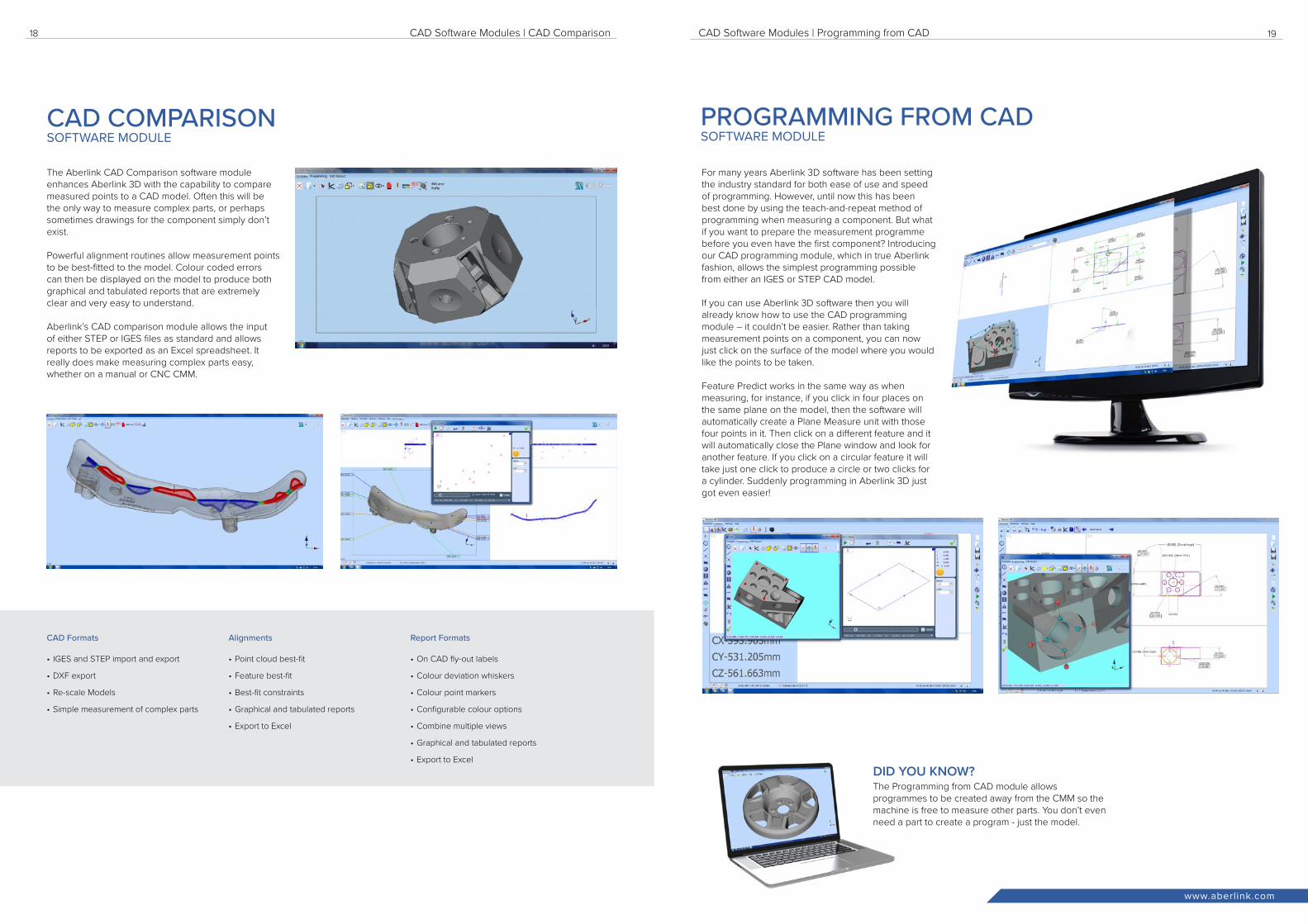
For many years Aberlink 3D software has been setting the industry standard for both ease of use and speed of programming. However, until now this has been best done by using the teach-and-repeat method of programming when measuring a component. But what if you want to prepare the measurement programme before you even have the first component? Introducing our CAD programming module, which in true Aberlink fashion, allows the simplest programming possible from either an IGES or STEP CAD model. If you can use Aberlink 3D software then you will already know how to use the CAD programming module – it couldn’t be easier. Rather than taking measurement points on a component, you can now just click on the surface of the model where you would like the points to be taken.
Feature Predict works in the same way as when measuring, for instance, if you click in four places on the same plane on the model, then the software will automatically create a Plane Measure unit with those four points in it. Then click on a different feature and it will automatically close the Plane window and look for another feature. If you click on a circular feature it will take just one click to produce a circle or two clicks for a cylinder. Suddenly programming in Aberlink 3D just got even easier!
CAD Software Modules | CAD Comparison CAD Software Modules | Programming from CAD
CAD COMPARISON SOFTWARE MODULE
PROGRAMMING FROM CAD SOFTWARE MODULE
CAD Formats
• IGES and STEP import and export
• DXF export
• Re-scale Models
• Simple measurement of complex parts
Alignments
• Point cloud best-fit
• Feature best-fit
• Best-fit constraints
• Graphical and tabulated reports
• Export to Excel
Report Formats
• On CAD fly-out labels
• Colour deviation whiskers
• Colour point markers
• Configurable colour options
• Combine multiple views
• Graphical and tabulated reports
• Export to Excel
The Programming from CAD module allows programmes to be created away from the CMM so the machine is free to measure other parts. You don’t even need a part to create a program - just the model.
DID YOU KNOW?

21
Key Features:
Key Features:
Key Features: Specification:
Y X
Z
20
www.aberlink.com
Aberlink’s camera system offers a non-contact facility on any Aberlink CMM. A clever design of magnetic, kinematic joint allows the probe and camera to be swapped in just seconds. This means that components can be inspected using both touch trigger and vision inspection technology on the same machine.
The camera incorporates a telecentric lens that gives a distortion-free image on the monitor. It also contains a fully programmable 16-LED light ring which contains alternate white and UV LEDs. The white LEDs provide surface illumination in the normal manner while the UV LEDs provide an ingenius solution to the perennial problem of backlighting on a CMM - the component to be measured is simply placed on a plate containing special reflective paper.
The Aberlink Vision software module allows Aberlink 3D software to be used for non-contact measuring. Fully automatic edge detection tools can be used in both manual and CNC mode ensuring fast and repeatable results without relying on the skill of the operator.
Powerful tools allow both geometric and complex shapes to be measured easily. Dimensions can either be called up by clicking on the measured features in the normal way, or alternatively measurement points can be best-fitted against a DXF file. As well as edge detection the operator may use either full cross hairs or mouse cross hairs with other advanced tools available including “smart measure”, centre line detection, an “all edge points” function, a “thread measure” tool and a “screen ruler” for quick measurements between any two points on the image.
A collimated back light option is available for when measuring 3D or small turned components - see accessories (inside back cover)
Project X finally replaces the old technology of a profile projector. It is easier to use than a profile projector. It is quicker to use than a profile projector and it will deliver reliable, consistant inspections time after time. Project X is available as either a manual machine or with full CNC control.
Project X is different. It utilises a totally new, patented technology XY scale, that records not only X and Y position but also any rotational movement of the camera system. In addition, this is an absolute scale system, which means as soon as you switch on the machine it knows exactly where it is - no need for referencing. The camera is free to glide around the measurement area mounted on a simple air bearing system, without any worry about constraining the mechanics to avoid losing accuracy.
Components can be placed on a glass table and remain stationary, while the camera is moved around taking measurements above. There is no need to secure the component on the table as there would be on a moving stage machine.
Combine this simple mechanical structure, made possible by the revolutionary scale technology, with the Aberlink measurement software and you will soon understand why Project X is the standard for 2-dimensional measurement.
Axis Travel (mm) Overall Size(mm) 2D Accuracy
X 400Y 300Z 125 (focus only)
X 583Y 722Z 670
7.5μm
Stand Off (mm) Field of View (mm) Temp Range
125.0 10.0 18 - 22°C
CMM Camera & Vision Software Project X
• Swap between touch probe and CMM camera in seconds
• Use touch and vision technology within the same inspection programme
• High precision edge detection for feature inspection
• Thread measurement - min/max/mean pitch, left/right angles, effective diameter
• Fully programmable digital zoom (no need to change lenses)
• Directional overhead lights and back light for profile and surface feature inspection
• Telecentric lens measures accurately even when the feature is out of focus
• Full colour video image
• CNC and manual machine controls
• Auto focus
• Digital Zoom
• Light intensity and direction
• Align to edge
• Automatic 2D profile scanning
• Scan geometric features
• Scan individual features
• Scan all visible features with a single mouse click
• Digitise 2D profiles - data export via DXF
• Sensor: 3 Mega pixel high speed colour camera
• Resolution: 2048 x 1536 (QXGA)
• Stand off: min 125mm | max 1000mm (manually adjusted)
• Field Of View: min 9.5mm | max 125mm
• Pixel Size: min 4.8µm | max 48µm
CMM CAMERA TOUCH & VISION ON THE SAME MACHINE
VISION SOFTWARE SOFTWARE MODULE
• High speed optical scanning - up to 5000 points/second
• Fully programmable digital zoom, no need to change lenses
• Powerful edge detection tools for maximum accuracy
• Aberlink’s easy-to-use vision measurement software
PROJECT X ADVANCED VISION SYSTEM
Technical Information:

2322
www.aberlink.com
CMM Touch Screen Joystick
The touch screen joystick gives you control of the Aberlink 3D inspection software and the 3-axis machine motion from an easy to operate handheld device.
The CMM touch screen joystick allows users complete control of the Aberlink 3D inspection software, clearly displayed through the unique joystick graphical user interface and high resolution touch sensitive screen - there is no need to interface with the PC. This is especially useful on larger CMMs when you need to stand over the part or around the back of the machine, to position the probe or clearly see probe measurements.
The colour touch screen joystick is invaluable when creating and running inspection programmes, enabling complete control of the X, Y and Z-axis machine movement, probe head indexing and machine status. You have complete control at your fingertips.
The touch screen joystick is supplied as standard with both the Zenith 3 and Azimuth CMMs.
Automatic Temperature Compensation
The Aberlink Temperature Compensation option enables your CMM to maintain accuracy in an uncontrolled environment, such as on the shop floor.
In an ideal world, your CMM would be installed in a perfectly temperature controlled room. However, in the real world of manufacturing, sometimes that isn’t possible or practical because you need your CMM next to where your parts are being made.
A USB temperature sensor embedded in the bridge of the CMM provides feedback to compensate as though measurements have been taken at 20°C
Fixture Kit
Patent pending T-slot and T-nut technology provides infinite adjustment of the fixture components in multiple directions. Clamps, locators and supports can be placed in exactly the right position to suit the part. Greater flexibility results in less complicated designs, fixtures are easier
to assemble and completed in less time.
Fixture mountings incorporate one or more t-slot. The slot receives a sliding t-nut which is used to secure the fixture components in place. For rapid repeat set-ups, fixture components can be removed and replaced without disturbing the t-nut while laser engraved scales and alpha markings facilitate more precise builds.
Any number of designs can be created from a single fixture kit. Over one hundred high quality parts manufactured from anodised aluminium and stainless steel are supplied in a compartmented storage case. All types of prismatic and free form parts can be held and supported correctly during measurement.
Collimated Back Light
The CMM collimated light enables backlight illumination of 3D or turned components when used with the CMM Camera System. When using collimated light to backlight components, a clear and crisp silhouette, similar to using a profile projector, is produced. A single-LED collimated light features a compact, lightweight design which is perfect for the Axiom too range of CMMs and is fully programmable and controllable within Aberlink vision software.
Industrial CMM Joystick
The industrial CMM joystick is a robust lower-cost version of the acclaimed CMM touch-screen joystick. It has full X-Y-Z axis motion control, X-Y-Z +/- direction measurement capability, feed rate override and the ability to insert Move Via points as required. The industrial joystick has been ergonomically designed for left or right handed operation, and includes a magnetic mount to enable quick placement on the CMM.
Automation Interface Unit
The Aberlink automation interface adds the capability for Aberlink 3D programs to be remotely controlled and monitored using an external system allowing any Aberlink CMM to be integrated with an automated component handling system, whether this be a fully controlled, PLC driven manufacturing system, a robotic loader or just an automatic bar feeder. The package comprises of an optically isolated digital I/O system and a software module that enables the software to be setup to follow a defined operating sequence to allow the automated operation.
The automation interface includes documentation and a software utility package, but because of the need to have detailed knowledge for the automated handling system for each installation, integration must be handled by the system integrator and cannot be supported by Aberlink.
CMM Accessories & Machine Options CMM Accessories & Machine Options
ACCESSORIES FURTHER CMM ENHANCEMENTS
Air Dryer
SMC IDFA series refrigeration air dryer - to ensure a good quality of air supply and maximise the performance and life of the CMM.
Dual Monitor
The vertically mounted dual-monitor arm enables Aberlink CAD or Vision software modules to be viewed on a separate tiltable screen to the Aberlink 3D inspection software.

The material in this document is for information only and is correct at the time of publication. Aberlink assumes no liability for any inaccuracies, errors or omissions and reserves the right to change specifications without notice. ©2018 Aberlink Ltd. All rights reserved. | Revision 4.7-2
The largest UK-owned manufacturer of coordinate measuring machines with a distribution and sales network spanning over 40 countries Worldwide.
www.aberlink.com
Aberlink LtdVatch Lane, Eastcombe, Gloucestershire GL6 7DYUnited Kingdom
T +44 (0) 1453 884461F +44 (0) 1453 882348E [email protected]
www.aberlink.com