NOMURA Kenichi, TAKEDA Takaaki Fundamental … · tion DCN (Data Communication Network). ......
5
Optical Submarine Cable Network Monitoring Equipment NOMURA Kenichi, TAKEDA Takaaki Abstract The introduction of large-capacity wavelength-division multiplexing and OADM (Optical Add/Drop Multiplexing) tech- nologies in optical submarine cable systems has led to an increase in the number of stations and complications in system configurations with regard to the necessity for connection management per wavelength band, etc. This trend has increased the need for submarine monitoring equipment that can control an entire network by crossing over the barriers of traditional management systems. This paper describes the requirements of operations management sys- tems that are capable of dealing with complicated optical submarine networks together with discussion of some of NEC’s solutions. Keywords EMS, UMS, monitoring, operations management, OADM, power feeding path 1. Introduction The optical submarine cable system is an advance from the traditional point-to-point or ring type systems to a mesh type network based on multipoint connections and OADM branch- ing. In the past, the main purpose of system monitoring equip- ment was to manage the operation status of equipment such as the submarine terminal equipment and power feeding equip- ment at each station. On the other hand, with the latest opti- cal submarine cable networks, complicated configurations have tended to increase. From the viewpoint of convenience of operation and maintenance such configurations need unified management of the networks, individual operations manage- ment for each OADM wavelength band and remote control of equipment in addition to management per station. This paper introduces optical submarine cable network mon- itoring equipment that can deal with mesh type networks based on large-capacity wavelength-division multiplexing and OADM technologies. Such monitoring equipment utilizes global web technologies and is composed of the WebNSV UMS (Unified Management System) for network monitoring and the WebNSV EMS (Element Management System) for station equipment monitoring. 2. Progress in Optical Submarine Networks and Operations Management Systems The previous mainstream transmission technology of opti- cal submarine cable systems was waveform-division multi- plexing of 10 Gbps × 64 or so waves, but the rapid dissemination of the Internet has increased the transmission capacity to 10 Gbps × 128 waves. To meet the need for trans- mission capacity for each landing station, the OADM technol- ogy that divides up the 128 waves into wavelengths using OADM Branching Units (BUs) is being put to practical use. Since the impact of faults is very important with such large- scale systems, it is now required to improve the reliability even further and to minimize service shutdowns and recover from circuit faults as quickly as possible. For this purpose, the network management systems need submarine monitoring equipment that can manage the entire network in addition to the traditional monitoring on a per-sta- tion basis. 3. NEC’s Optical Submarine Cable Network Operations Management Solutions With NEC’s solutions for the operations management of NEC TECHNICAL JOURNAL Vol.5 No.1/2010 ------- 33 Fundamental Technologies and Devices
Transcript of NOMURA Kenichi, TAKEDA Takaaki Fundamental … · tion DCN (Data Communication Network). ......
Optical Submarine Cable Network MonitoringEquipmentNOMURA Kenichi, TAKEDA Takaaki
AbstractThe introduction of large-capacity wavelength-division multiplexing and OADM (Optical Add/Drop Multiplexing) tech-nologies in optical submarine cable systems has led to an increase in the number of stations and complications insystem configurations with regard to the necessity for connection management per wavelength band, etc. This trendhas increased the need for submarine monitoring equipment that can control an entire network by crossing over thebarriers of traditional management systems. This paper describes the requirements of operations management sys-tems that are capable of dealing with complicated optical submarine networks together with discussion of some ofNEC’s solutions.
Keywords
EMS, UMS, monitoring, operations management, OADM, power feeding path
1. Introduction
The optical submarine cable system is an advance from thetraditional point-to-point or ring type systems to a mesh typenetwork based on multipoint connections and OADM branch-ing. In the past, the main purpose of system monitoring equip-ment was to manage the operation status of equipment such asthe submarine terminal equipment and power feeding equip-ment at each station. On the other hand, with the latest opti-cal submarine cable networks, complicated configurationshave tended to increase. From the viewpoint of convenience ofoperation and maintenance such configurations need unifiedmanagement of the networks, individual operations manage-ment for each OADM wavelength band and remote control ofequipment in addition to management per station.
This paper introduces optical submarine cable network mon-itoring equipment that can deal with mesh type networks basedon large-capacity wavelength-division multiplexing andOADM technologies. Such monitoring equipment utilizesglobal web technologies and is composed of the WebNSVUMS (Unified Management System) for network monitoringand the WebNSV EMS (Element Management System) forstation equipment monitoring.
2. Progress in Optical Submarine Networks and OperationsManagement Systems
The previous mainstream transmission technology of opti-cal submarine cable systems was waveform-division multi-plexing of 10 Gbps × 64 or so waves, but the rapiddissemination of the Internet has increased the transmissioncapacity to 10 Gbps × 128 waves. To meet the need for trans-mission capacity for each landing station, the OADM technol-ogy that divides up the 128 waves into wavelengths usingOADM Branching Units (BUs) is being put to practical use.Since the impact of faults is very important with such large-scale systems, it is now required to improve the reliability evenfurther and to minimize service shutdowns and recover fromcircuit faults as quickly as possible.
For this purpose, the network management systems needsubmarine monitoring equipment that can manage the entirenetwork in addition to the traditional monitoring on a per-sta-tion basis.
3. NEC’s Optical Submarine Cable Network OperationsManagement Solutions
With NEC’s solutions for the operations management of
NEC TECHNICAL JOURNAL Vol.5 No.1/2010 ------- 33
Fundamental Technologies and Devices
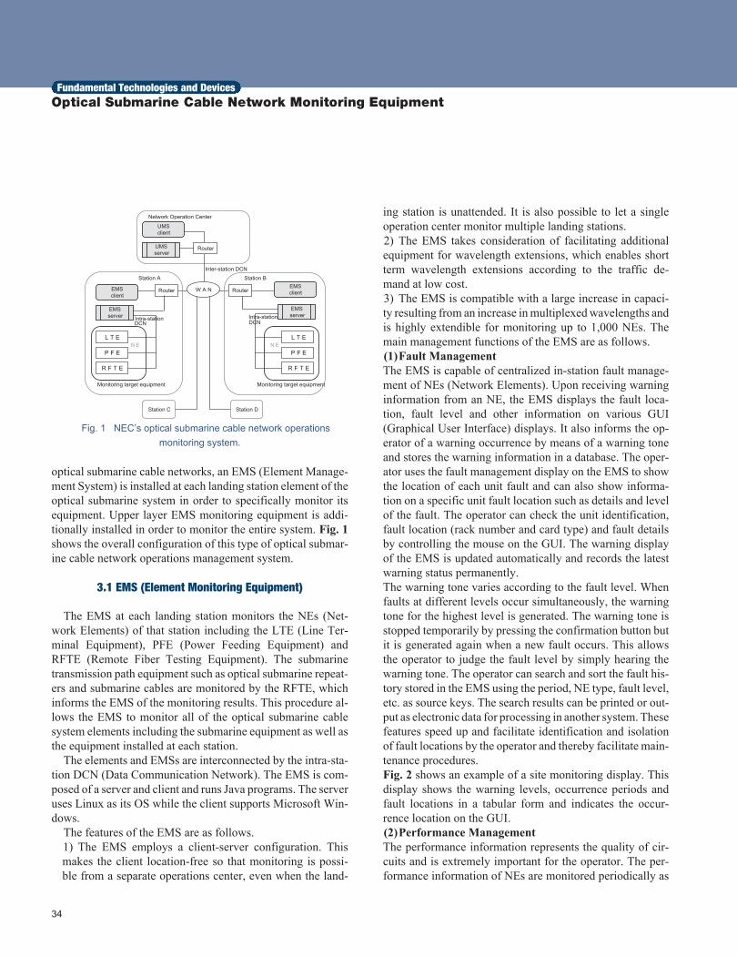
Fig. 1 NEC’s optical submarine cable network operationsmonitoring system.
optical submarine cable networks, an EMS (Element Manage-ment System) is installed at each landing station element of theoptical submarine system in order to specifically monitor itsequipment. Upper layer EMS monitoring equipment is addi-tionally installed in order to monitor the entire system. Fig. 1shows the overall configuration of this type of optical submar-ine cable network operations management system.
3.1 EMS (Element Monitoring Equipment)
The EMS at each landing station monitors the NEs (Net-work Elements) of that station including the LTE (Line Ter-minal Equipment), PFE (Power Feeding Equipment) andRFTE (Remote Fiber Testing Equipment). The submarinetransmission path equipment such as optical submarine repeat-ers and submarine cables are monitored by the RFTE, whichinforms the EMS of the monitoring results. This procedure al-lows the EMS to monitor all of the optical submarine cablesystem elements including the submarine equipment as well asthe equipment installed at each station.
The elements and EMSs are interconnected by the intra-sta-tion DCN (Data Communication Network). The EMS is com-posed of a server and client and runs Java programs. The serveruses Linux as its OS while the client supports Microsoft Win-dows.
The features of the EMS are as follows.1) The EMS employs a client-server configuration. Thismakes the client location-free so that monitoring is possi-ble from a separate operations center, even when the land-
ing station is unattended. It is also possible to let a singleoperation center monitor multiple landing stations.2) The EMS takes consideration of facilitating additionalequipment for wavelength extensions, which enables shortterm wavelength extensions according to the traffic de-mand at low cost.3) The EMS is compatible with a large increase in capaci-ty resulting from an increase in multiplexed wavelengths andis highly extendible for monitoring up to 1,000 NEs. Themain management functions of the EMS are as follows.(1)Fault ManagementThe EMS is capable of centralized in-station fault manage-ment of NEs (Network Elements). Upon receiving warninginformation from an NE, the EMS displays the fault loca-tion, fault level and other information on various GUI(Graphical User Interface) displays. It also informs the op-erator of a warning occurrence by means of a warning toneand stores the warning information in a database. The oper-ator uses the fault management display on the EMS to showthe location of each unit fault and can also show informa-tion on a specific unit fault location such as details and levelof the fault. The operator can check the unit identification,fault location (rack number and card type) and fault detailsby controlling the mouse on the GUI. The warning displayof the EMS is updated automatically and records the latestwarning status permanently.The warning tone varies according to the fault level. Whenfaults at different levels occur simultaneously, the warningtone for the highest level is generated. The warning tone isstopped temporarily by pressing the confirmation button butit is generated again when a new fault occurs. This allowsthe operator to judge the fault level by simply hearing thewarning tone. The operator can search and sort the fault his-tory stored in the EMS using the period, NE type, fault level,etc. as source keys. The search results can be printed or out-put as electronic data for processing in another system. Thesefeatures speed up and facilitate identification and isolationof fault locations by the operator and thereby facilitate main-tenance procedures.Fig. 2 shows an example of a site monitoring display. Thisdisplay shows the warning levels, occurrence periods andfault locations in a tabular form and indicates the occur-rence location on the GUI.(2)Performance ManagementThe performance information represents the quality of cir-cuits and is extremely important for the operator. The per-formance information of NEs are monitored periodically as
34
Fundamental Technologies and Devices Optical Submarine Cable Network Monitoring Equipment
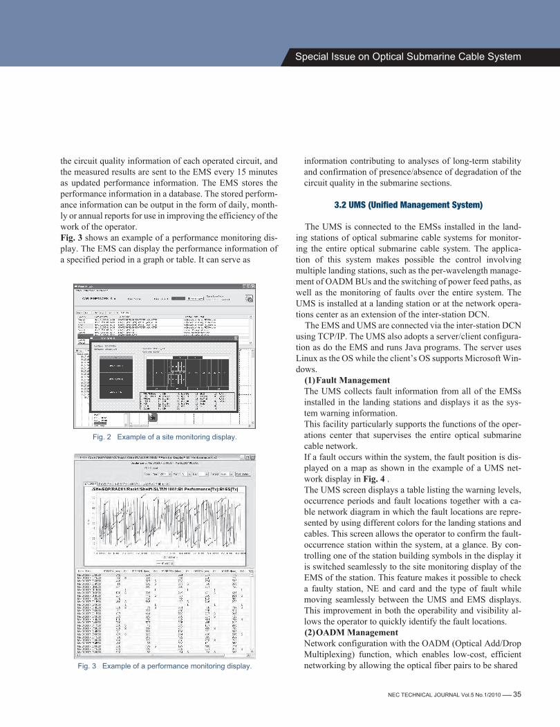
the circuit quality information of each operated circuit, andthe measured results are sent to the EMS every 15 minutesas updated performance information. The EMS stores theperformance information in a database. The stored perform-ance information can be output in the form of daily, month-ly or annual reports for use in improving the efficiency of thework of the operator.Fig. 3 shows an example of a performance monitoring dis-play. The EMS can display the performance information ofa specified period in a graph or table. It can serve as
Fig. 2 Example of a site monitoring display.
Fig. 3 Example of a performance monitoring display.
information contributing to analyses of long-term stabilityand confirmation of presence/absence of degradation of thecircuit quality in the submarine sections.
3.2 UMS (Unified Management System)
The UMS is connected to the EMSs installed in the land-ing stations of optical submarine cable systems for monitor-ing the entire optical submarine cable system. The applica-tion of this system makes possible the control involvingmultiple landing stations, such as the per-wavelength manage-ment of OADM BUs and the switching of power feed paths, aswell as the monitoring of faults over the entire system. TheUMS is installed at a landing station or at the network opera-tions center as an extension of the inter-station DCN.
The EMS and UMS are connected via the inter-station DCNusing TCP/IP. The UMS also adopts a server/client configura-tion as do the EMS and runs Java programs. The server usesLinux as the OS while the client’s OS supports Microsoft Win-dows.
(1)Fault ManagementThe UMS collects fault information from all of the EMSsinstalled in the landing stations and displays it as the sys-tem warning information.This facility particularly supports the functions of the oper-ations center that supervises the entire optical submarinecable network.If a fault occurs within the system, the fault position is dis-played on a map as shown in the example of a UMS net-work display in Fig. 4 .The UMS screen displays a table listing the warning levels,occurrence periods and fault locations together with a ca-ble network diagram in which the fault locations are repre-sented by using different colors for the landing stations andcables. This screen allows the operator to confirm the fault-occurrence station within the system, at a glance. By con-trolling one of the station building symbols in the display itis switched seamlessly to the site monitoring display of theEMS of the station. This feature makes it possible to checka faulty station, NE and card and the type of fault whilemoving seamlessly between the UMS and EMS displays.This improvement in both the operability and visibility al-lows the operator to quickly identify the fault locations.(2)OADM ManagementNetwork configuration with the OADM (Optical Add/DropMultiplexing) function, which enables low-cost, efficientnetworking by allowing the optical fiber pairs to be shared
NEC TECHNICAL JOURNAL Vol.5 No.1/2010 ------- 35
Special Issue on Optical Submarine Cable System
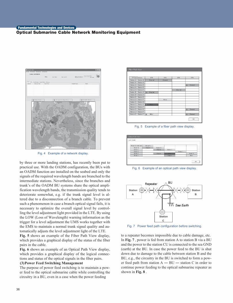
Fig. 4 Example of a network display.
by three or more landing stations, has recently been put topractical use. With the OADM configuration, the BUs withan OADM function are installed on the seabed and only thesignals of the required wavelength bands are branched to theintermediate stations. Nevertheless, since the branches andtrunk’s of the OADM BU systems share the optical ampli-fication wavelength bands, the transmission quality tends todeteriorate somewhat, e.g. if the trunk signal level is al-tered due to a disconnection of a branch cable. To preventsuch a phenomenon in case a branch optical signal fails, it isnecessary to optimize the overall signal level by control-ling the level adjustment light provided in the LTE. By usingthe LOW (Loss of Wavelength) warning information as thetrigger for a level adjustment the UMS works together withthe EMS to maintain a normal trunk signal quality and au-tomatically adjusts the level adjustment light of the LTE.Fig. 5 shows an example of the Fiber Path View display,which provides a graphical display of the status of the fiberpairs in the cable.Fig. 6 shows an example of an Optical Path View display,which provides a graphical display of the logical connec-tions and status of the optical signals in the fiber pairs.(3)Power Feed Switching ManagementThe purpose of power feed switching is to maintain a pow-er feed to the optical submarine cable while controlling thecircuitry in a BU, even in a case when the power feeding
Fig. 5 Example of a fiber path view display.
Fig. 6 Example of an optical path view display.
Fig. 7 Power feed path configuration before switching.
to a repeater becomes impossible due to cable damage, etc.In Fig. 7 , power is fed from station A to station B via a BUand the power to the station CU is connected to the sea GND(earth) at the BU. In case the power feed to the BU is shutdown due to damage to the cable between station B and theBU, e.g., the circuitry in the BU is switched to form a pow-er feed path from station A ― BU ― station C in order tocontinue power feeding to the optical submarine repeater asshown in Fig. 8 .
36
Fundamental Technologies and Devices Optical Submarine Cable Network Monitoring Equipment
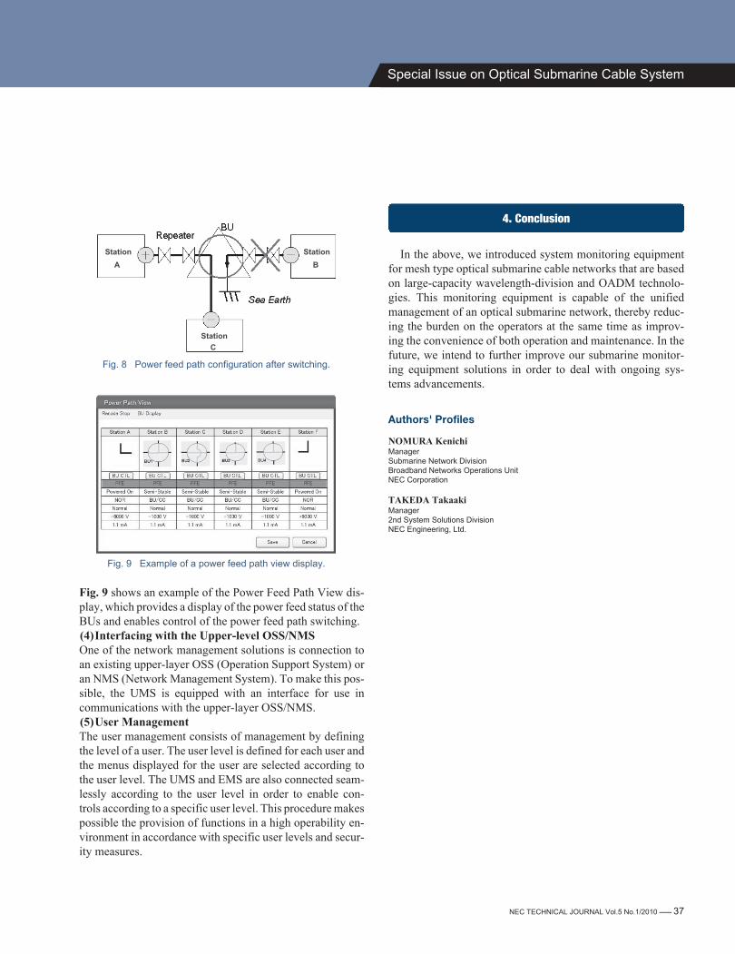
Fig. 8 Power feed path configuration after switching.
Fig. 9 Example of a power feed path view display.
Fig. 9 shows an example of the Power Feed Path View dis-play, which provides a display of the power feed status of theBUs and enables control of the power feed path switching.(4)Interfacing with the Upper-level OSS/NMSOne of the network management solutions is connection toan existing upper-layer OSS (Operation Support System) oran NMS (Network Management System). To make this pos-sible, the UMS is equipped with an interface for use incommunications with the upper-layer OSS/NMS.(5)User ManagementThe user management consists of management by definingthe level of a user. The user level is defined for each user andthe menus displayed for the user are selected according tothe user level. The UMS and EMS are also connected seam-lessly according to the user level in order to enable con-trols according to a specific user level. This procedure makespossible the provision of functions in a high operability en-vironment in accordance with specific user levels and secur-ity measures.
4. Conclusion
In the above, we introduced system monitoring equipmentfor mesh type optical submarine cable networks that are basedon large-capacity wavelength-division and OADM technolo-gies. This monitoring equipment is capable of the unifiedmanagement of an optical submarine network, thereby reduc-ing the burden on the operators at the same time as improv-ing the convenience of both operation and maintenance. In thefuture, we intend to further improve our submarine monitor-ing equipment solutions in order to deal with ongoing sys-tems advancements.
Authors' Profiles
NOMURA KenichiManagerSubmarine Network DivisionBroadband Networks Operations UnitNEC Corporation
TAKEDA TakaakiManager2nd System Solutions DivisionNEC Engineering, Ltd.
NEC TECHNICAL JOURNAL Vol.5 No.1/2010 ------- 37
Special Issue on Optical Submarine Cable System