NOMSA MOJELA - CAA Incursions Excursions Workshop...Nomsa Mojela 083 461 6506 Mahlubandile Vuba 083...
27
+ NOMSA MOJELA
Transcript of NOMSA MOJELA - CAA Incursions Excursions Workshop...Nomsa Mojela 083 461 6506 Mahlubandile Vuba 083...
+
NOMSA MOJELA
PRESENTATION OVERVIEW
ICAO AGL Definition.
Four Elements of AGL.
Airfield Classification and Categories of
Operation.
Systems Needed for Different Categories.
System Maintenance For Runway Lighting.
Taxiways And Apron Lighting.
System Maintenance for Taxiway Lighting.
Surface Movement Guidance System & Control
Systems.
Mains And Standby Power SUPPLY
ICAO ANNEX 14 VOLUME 1 DEFINITION
OF AIRPORT GROUND LIGHTHING.
“Any light specially provided as an aid to aircraft
navigation, other than a light displayed on an
aircraft.”
AGL contains four main elements and are
referred to as the “FOUR C’s”
• CONFIGURATION
• COLOUR
• CANDELAS
• COVERAGE

Configuration • Pattern
• Spacing
• Distance
Colour • Identification
• Instruct
• Inform
• Increase Conspicuity
Candelas • Output
• Illuminance
Coverage • Horizontally and Vertically
• Lenses
Of these four elements in AGL theory and
practice it should be noted that:
Configuration and Colour are fundamentally
the responsibility of the designer.
Candela and Coverage whilst also specified
in design standards, rely primarily on the
maintainer.
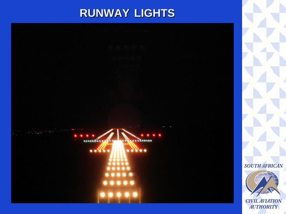
RUNWAY LIGHTS

TYPES OF LIGHTS FOUND
ON THE RUNWAY

AIRFIELD CLASSIFICATION AND
CATEGORIES OF OPERATIONS
Instrument Runway- A runway intended for the
operation of aircraft using instrument approach
procedures.
Non Instrument Runway- A runway intended
for the operation of aircraft using visual
approach procedures.
Instrument (non-precision) approach
runway- An instrument runway served by visual
aids or non visual aid providing at least
directional guidance adequate for straight in
approach.
Precision Approach Runway- An instrument
runway served by an Instrument Landing
System (ILS) and visual aids for operations
down to:
Category I – RVR of 550 meters
Category II - RVR of 300 meters
Category IIIA - RVR of 175 meters
Category IIIB – RVR of 50 meters
Category IIIC - Visibility nil
Where Runway Visual Range (RVR) is referred to
as the range over which the pilot of an aircraft on
the centre of a runway can see the runway surface
markings or the lights delineating the runway or
identifying its centre line.

SYSTEMS NEEDED FOR CATEGORIES
CAT I RVR OF 550M
900m Approach Lighting (Barrette or Distance
coded system).
Threshold Lights
Runway Edge Lights
Runway End Lights
Wing Bar Lights
4 Precision Approach Path Indicators

CAT II & III RVR OF 300-175m
All CAT I systems
Side Row Barrettes (Supplementary Approach
Lights)
Runway Centre Line Lights
Touch Down Zone Lights
NOTE: Each system must be wired with two
circuits, interleaving patterns. (As defined in ICAO
Aerodrome Design Manual Part 5, Electrical
Systems).
System Maintenance for CAT I
85 PER CENT OF THESE SYSTEMS SHALL BE
SERVICEABLE.
Precision Approach Category I Lighting System
Runway Threshold Lights
Runway Edge Lights
Runway End Lights
AT LEAST 95 PER CENT of the lights are
serviceable in the Runway Centre Line Lights
(where provided).

System Maintenance for CAT II & III
95 PER CENT OF THESE SYSTEMS SHALL BE
SERVICEABLE.
Precision Approach Category II and III Lighting
System, the inner 450 m
Runway Centre Line Lights
Runway Threshold Lights
Runway Edge Lights
90 PER CENT of the lights are serviceable in
the Touchdown Zone Lights.
85 PER CENT of the lights are serviceable in
the Approach Lighting System beyond 450 m.
75 PER CENT of the lights are serviceable in
the Runway End Lights.
System Maintenance for Non Precision
Runways
All runway lights shall be serviceable and that,
in any event, at least 85 per cent of the lights
are serviceable in the runway edge lights and
runway end lights.
NOTE: In order to provide continuity of guidance,
the allowable percentage of unserviceable lights
shall not be permitted in such a way as to alter the
basic pattern of the lighting system.
Additionally, an unserviceable light shall not be
permitted adjacent to another unserviceable light,
except in a barrette or a crossbar where two
adjacent unserviceable lights may be permitted.
Maintenance of AGL
WHEN SHOULD MAINTENANCE ON AGL BE
DONE?
100% light output SERVICEABLE.
70% light output NEEDS MAINTENANCE.
50% light out put UNSERVICEABLE.
HOW TO ENSURE SERVICEABILITY LEVELS?
BY Managing The AGL Maintenance Loop:
Measure - Photometric Performance
Maintain - Take remedial measures
Monitor - Continual Measurement
Manage - Procedures and Actions
TAXIWAY AND APRON LIGHTING
There are two distinct lighting systems employed
for showing pilots the route to be followed when
taxiing aircraft to and from the Runway or the
extent to the Apron.
BLUE Edge Lighting
GREEN Centreline Lighting (Mandatory for
CAT II & III)
Other Services installed that interface with the
Edge or Centreline lighting but function as
separate systems are:
Stop Bar Lights
Runway Guide Lights

Lead On Lights
Lead Off Lights (Rapid Exit Taxiway Lights)
Rapid Exit Taxiway Indicator Lights
System Maintenance for Taxiways
Taxiway lights intended for use in CAT II & III
runways, no two adjacent Taxiway Centre Line
Lights shall be unserviceable.
Stop Bars Lights intended for use in CAT II & III
runways, there shall be:
No more than two lights unserviceable.
No two adjacent lights will not remain
unserviceable unless the light spacing is
significantly less than that specified.
ANNEX 14 Vol 1 Chapter 10
ICAO Doc Part 9, Airport Maintenance
Practices

SMGS & CS FOR CAT II & III
OPERATIONS
A surface movement guidance and control system
(SMGCS) shall be provided at an aerodrome.
The design of an SMGCS should take into
account:
The density of air traffic;
The visibility conditions under which operations
are intended;
The need for pilot orientation;
The complexity of the aerodrome layout; and
Movements of vehicles.

Where an SMGCS is provided by selective
switching of stop bars and taxiway centre line
lights, the following requirements shall be met:
Taxiway routes which are indicated by
illuminated taxiway centre line lights shall be
capable of being terminated by an illuminated
stop bar.
The control circuits shall be so arranged that
when a stop bar located ahead of an aircraft is
illuminated, the appropriate section of taxiway
centre line lights beyond it is suppressed
(Interlocking).
The taxiway centre line lights are activated
ahead of an aircraft when the stop bar is
suppressed (Interlocking).
Surface Movement Radar
Surface movement radar for the manoeuvring
area should be provided at an aerodrome
intended for use in runway visual range
conditions less than a value of 350 m (CAT III).
Surface movement radar for the manoeuvring
area should be provided at an aerodrome when
traffic density and operating conditions are such
that regularity of traffic flow cannot be
maintained by alternative procedures and
facilities.
ANNEX 14 Chapter 5 & 9
ICAO Doc 9830
SACAA TGM for SMGS Advisory Circular.

MAINS AND STANDBY POWER SUPPLY
There are number of priority circuits in various
locations on the airport that able to operate with
short break in power supply and some areas
must retain continuity of services with no break
in power supply.
The three categories of power supply operated
in most airports are:
No- Break Services
Essential Services
Non- Essential Services

NO- BREAK SERVICES
Air Traffic Control Tower.
Operations Building.
Communication Centre.
CAT II and III AGL systems sub station.
ESSENTIAL SERVICES
CAT I AGL Systems.
Airport Fire and Rescue operation building.
Airport Terminal Building.
Water pumping station.
Meteorological Forecast Office complex.
Remote VHF/HF Radio Transmitter and
Receiver stations.
All Navaids Systems

NON- ESSENTIAL SERVICES
Services not included on the two of above
categories, will switch back to normal operation
once main power has been fully restored.
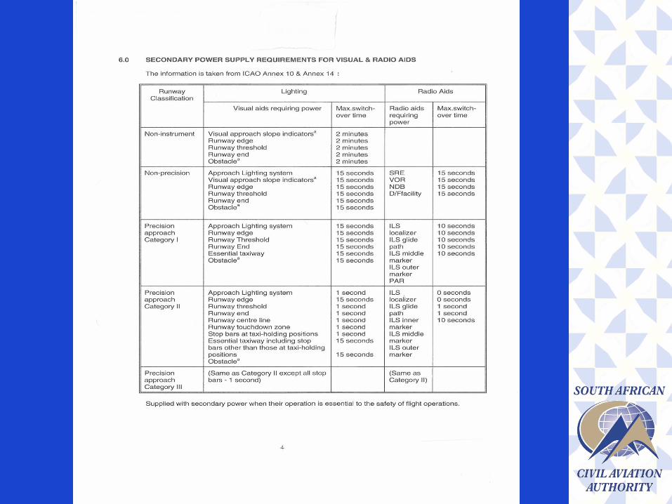
ANNEX 14 Chapter 8 Table 8-1 Provides the
Secondary Power Supply Requirements for
Visual & Radio Aids.

Thank you
SACAA Electrical Infrastructure
Inspectors:
Nomsa Mojela 083 461 6506
Mahlubandile Vuba 083 461 6708
Vincent Mulaudzi 083 461 6540

QUESTIONS