Nomographs to obtain three dimensional (3D) elastic ...
11
12 Equihua-Anguiano, L.N., Orozco-Calderón, M., and Hernández-Madrigal, V.M. (2020). Nomographs to obtain three dimensional (3D) elastic displacements for deep circular tunnels. 28, 12-22 Nomographs to obtain three dimensional (3D) elastic displacements for deep circular tunnels Luisa N. Equihua-Anguiano 1 , Marcos Orozco-Calderón 2 and V. Manuel Hernández-Madrigal 3 1 Faculty of Civil Engineering, Universidad Michoacana de San Nicolás de Hidalgo, Felicitas del Río, Morelia, Michoacán, CP 58030, Mexico, [email protected] (Orcid: 0000-0001-8295-8041) 2 Research, Instituto Mexicano del Petróleo IMP, Camino de Terracería No. 800, Col. San José Novillero, Boca del Río, Veracruz, CP 94286, Mexico, [email protected] (Orcid: 0000-0002-9365-9511) 3 Institute of Earth Sciences, Universidad Michoacana de San Nicolás de Hidalgo, Felicitas del Río, Morelia, Michoacán, CP 58030, Mexico, [email protected] (Orcid: 0000-0003-1287-0911) Nomogramas para obtener desplazamientos elásticos tridimensionales (3D) en túneles circulares Fecha de entrega: 13 de marzo 2020 Fecha de aceptación: 10 de septiembre 2020 Finite element (FEM) based software is frequently used in practice for tunnel design, alongside the traditional analytical and empirical solutions. Design is not the only challenge in this kind of projects, there are other important factors such as considering what is necessary to develop an efficient construction plan under a schedule and foreseeing possible changes that modify the original design. The use of two-dimensional (2D) FEM is one of the main tools used in the industry. However, 2D results yield not an entirely accurate analysis, since the behaviour of the infrastructure is considered as three- dimensional (3D). This paper presents nomographs and a 3D and 2D relationship, to rapidly estimate values of elastic 3D and 2D displacements produced in the periphery of a deep circular tunnel, inside soils of different rigidities. Graphics given correspond to five different radii and for a 100 m excavation length. Nomographs were obtained from RS3© and RS2© FEM simulations and according to the elastic theory. Geotechnical parameters correspond to a constant friction angle, cohesion and soil specific weight. FEM analysis was made using the Mohr-Coulomb model, considering isotropic conditions. Keywords: nomograph, finite element method FEM, circular tunnel, elastic analysis El método de elementos finitos (FEM) se utiliza frecuentemente en la práctica para el diseño de túneles, junto con las soluciones analíticas y empíricas tradicionales. El diseño no es el único desafío en este tipo de proyectos, existen otros factores importantes como considerar lo necesario para desarrollar un plan constructivo eficiente bajo un cronograma y prever posibles cambios que modifiquen el diseño original. El uso de FEM bidimensional (2D) es una de las principales herramientas utilizadas en la industria. Sin embargo, los resultados 2D proporcionan un análisis no del todo preciso, ya que el comportamiento de la infraestructura se considera tridimensional (3D). Este trabajo presenta nomogramas y una relación entre 3D y 2D para estimar valores de desplazamientos elásticos 3D y 2D, producidos en la periferia de un túnel circular profundo, dentro de suelos de diferentes rigideces. Los gráficos corresponden a cinco radios diferentes de túneles y para una longitud de excavación de 100 m. Los nomogramas se obtuvieron a partir de simulaciones FEM RS3© y RS2© y de acuerdo con la teoría elástica. Los parámetros geotécnicos corresponden a un ángulo de fricción constante, cohesión y peso específico del suelo. El análisis FEM se realizó utilizando el modelo de Mohr-Coulomb, considerando condiciones isotrópicas. Palabras clave: nomograma, método de elementos finitos, túnel circular, análisis elástico Introduction Tunnel techniques have been developed in soils and rocks for several thousands of years. Although there are reports of modern tunnelling theories, the first challenges to set up design methods and techniques for tunnel construction were initiated by Terzaghi (1942, 1946), through implementing
Transcript of Nomographs to obtain three dimensional (3D) elastic ...
12
Equihua-Anguiano, L.N., Orozco-Calderón, M., and Hernández-Madrigal, V.M. (2020). Nomographs to obtain three dimensional (3D) elastic displacements for deep circular tunnels.
28, 12-22
Nomographs to obtain three dimensional (3D) elastic displacements for deep circular tunnels
Luisa N. Equihua-Anguiano1, Marcos Orozco-Calderón2 and V. Manuel Hernández-Madrigal31 Faculty of Civil Engineering, Universidad Michoacana de San Nicolás de Hidalgo, Felicitas del Río, Morelia, Michoacán, CP 58030, Mexico, [email protected] (Orcid: 0000-0001-8295-8041)
2 Research, Instituto Mexicano del Petróleo IMP, Camino de Terracería No. 800, Col. San José Novillero, Boca del Río, Veracruz, CP 94286, Mexico, [email protected] (Orcid: 0000-0002-9365-9511)
3 Institute of Earth Sciences, Universidad Michoacana de San Nicolás de Hidalgo, Felicitas del Río, Morelia, Michoacán, CP 58030, Mexico, [email protected] (Orcid: 0000-0003-1287-0911)
Nomogramas para obtener desplazamientos elásticos tridimensionales (3D) en túneles circulares
Fecha de entrega: 13 de marzo 2020Fecha de aceptación: 10 de septiembre 2020
Finite element (FEM) based software is frequently used in practice for tunnel design, alongside the traditional analytical and empirical solutions. Design is not the only challenge in this kind of projects, there are other important factors such as considering what is necessary to develop an efficient construction plan under a schedule and foreseeing possible changes that modify the original design. The use of two-dimensional (2D) FEM is one of the main tools used in the industry. However, 2D results yield not an entirely accurate analysis, since the behaviour of the infrastructure is considered as three-dimensional (3D). This paper presents nomographs and a 3D and 2D relationship, to rapidly estimate values of elastic 3D and 2D displacements produced in the periphery of a deep circular tunnel, inside soils of different rigidities. Graphics given correspond to five different radii and for a 100 m excavation length. Nomographs were obtained from RS3© and RS2© FEM simulations and according to the elastic theory. Geotechnical parameters correspond to a constant friction angle, cohesion and soil specific weight. FEM analysis was made using the Mohr-Coulomb model, considering isotropic conditions.
Keywords: nomograph, finite element method FEM, circular tunnel, elastic analysis
El método de elementos finitos (FEM) se utiliza frecuentemente en la práctica para el diseño de túneles, junto con las soluciones analíticas y empíricas tradicionales. El diseño no es el único desafío en este tipo de proyectos, existen otros factores importantes como considerar lo necesario para desarrollar un plan constructivo eficiente bajo un cronograma y prever posibles cambios que modifiquen el diseño original. El uso de FEM bidimensional (2D) es una de las principales herramientas utilizadas en la industria. Sin embargo, los resultados 2D proporcionan un análisis no del todo preciso, ya que el comportamiento de la infraestructura se considera tridimensional (3D). Este trabajo presenta nomogramas y una relación entre 3D y 2D para estimar valores de desplazamientos elásticos 3D y 2D, producidos en la periferia de un túnel circular profundo, dentro de suelos de diferentes rigideces. Los gráficos corresponden a cinco radios diferentes de túneles y para una longitud de excavación de 100 m. Los nomogramas se obtuvieron a partir de simulaciones FEM RS3© y RS2© y de acuerdo con la teoría elástica. Los parámetros geotécnicos corresponden a un ángulo de fricción constante, cohesión y peso específico del suelo. El análisis FEM se realizó utilizando el modelo de Mohr-Coulomb, considerando condiciones isotrópicas.
Palabras clave: nomograma, método de elementos finitos, túnel circular, análisis elástico
IntroductionTunnel techniques have been developed in soils and rocks for several thousands of years. Although there are reports
of modern tunnelling theories, the first challenges to set up design methods and techniques for tunnel construction were initiated by Terzaghi (1942, 1946), through implementing
13
Equihua-Anguiano, L.N., Orozco-Calderón, M., and Hernández-Madrigal, V.M. (2020). 28, 12-22
design rules for primary supports. In the same manner Broms and Bennermark (1967) contributed with the study of vertical excavations and Peck (1969) established other concepts related to tunnel support, as well as for the evaluation of the superficial settlements. Subsequently, criteria of analysis were developed to establish analytical and empirical methods, which focused on reviewing the face and in the general stability of the tunnel. On one side, empirical methods which are established on the experience gained in practice provide a useful solution, such as those by Bieniawski (1989) and Hoek and Brown (1980, 1997), among others. On the other hand, the analytical methods in addition to the experience formulation, include the soil mechanics principles, for example methods applied in soils by Tamez (1984) and Moreno and Schmmitter (1981). Analytical solutions for stress and displacement fields around a tunnel and in the lining are presented by Pérez and Auvinet (2012) for soils under drained conditions. The references that apply to rocks are Hoek and Marinos (2000) and Duncan Fama (1993). Nevertheless, it is important to understand the limitations of rock mass classification schemes (Palmstrom and Broch, 2006). Nowadays, tunnel design employs two (2D) and three (3D) dimensional software, based on numerical methods. In general these methods are used to study particular tunnel cases (e.g. Sánchez et al., 2014; Farias et al., 2004, Martínez et al., 2015). In the same way, 3D numerical models develop a more realistic and efficient design than 2D models. However, low computer resources and design exigency do not make 3D one of the preferred methods for the construction industry. Thus, to avoid long calculations,
there is a methodology based on the finite element method FEM which allows obtaining a 3D response from 2D FEM analyses (Vlachopoulos and Diederichs, 2014). This methodology was obtained from a 2D FEM numerical model which is established under the constitutive model principles of Hoek et al. (2002). Moreover, it is necessary to study possibilities to interpolate results from 2D to 3D models in soils, given that the infrastructure development has increased demands for the construction of large tunnels (Hoek, 2001).
Considering the previous statements, this article presents a parametric study that allow obtaining nomographs to estimate 3D elastic displacements in a rapid way, for a circular tunnel under drained conditions. The presented graphs have also the importance of revealing the 3D effect since the 3D deformations are not the same that those obtained from a 2D analysis along a certain excavation length. It is also possible to calculate the 2D-3D relationship from the 3D tunnel displacements for the first meters of the tunnel excavation. Undrained conditions and the presence of groundwater table are not included in this study.
Tunnel characteristics and numerical FEM considerationsTunnel geometry, dimensions and numerical characteristics are presented in this section, as well as the soil parameters and the field pressure variation used in the FEM models.
Geometry modelsThe considered tunnel geometry corresponds to a simulation of a deep tunnel, taking into account FEM
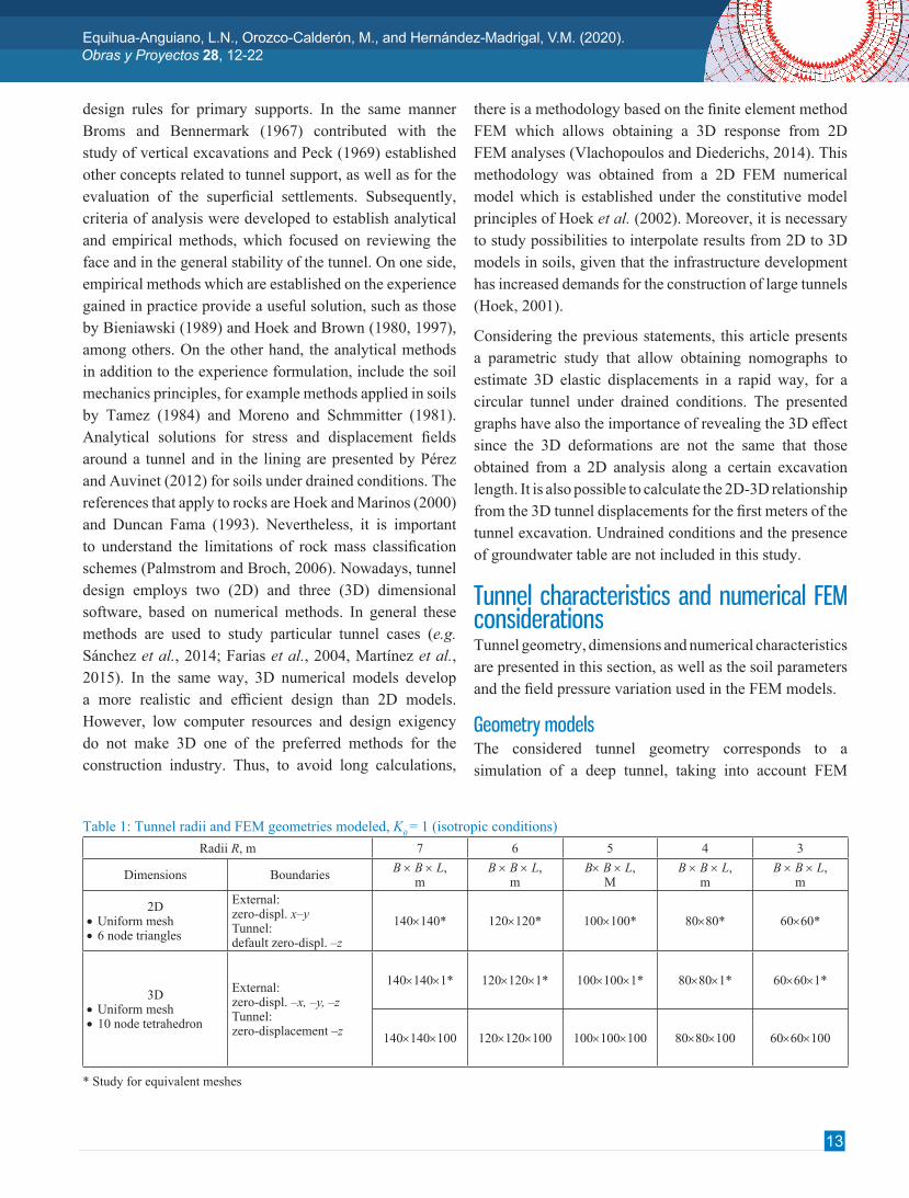
Table 1: Tunnel radii and FEM geometries modeled, K0 = 1 (isotropic conditions)Radii R, m 7 6 5 4 3
Dimensions Boundaries B × B × L, m
B × B × L, m
B× B × L, M
B × B × L, m
B × B × L, m
2D•Uniform mesh•6 node triangles
External:zero-displ. x–yTunnel:default zero-displ. –z
140×140* 120×120* 100×100* 80×80* 60×60*
3D•Uniform mesh•10 node tetrahedron
External:zero-displ. –x, –y, –zTunnel:zero-displacement –z
140×140×1* 120×120×1* 100×100×1* 80×80×1* 60×60×1*
140×140×100 120×120×100 100×100×100 80×80×100 60×60×100
* Study for equivalent meshes

14
Equihua-Anguiano, L.N., Orozco-Calderón, M., and Hernández-Madrigal, V.M. (2020). Nomographs to obtain three dimensional (3D) elastic displacements for deep circular tunnels.
28, 12-22
model dimensions of width and total depth that do not affect numerical convergence or results. A square geometry was assumed as the analysis domain with B × B dimensions, where B = 20R as represented in Figure 1a. The depth H0 from the ground surface to the center of the excavation in function of the tunnel radius R and different excavation lengths L until L = 100 m for the 3D-model were simulated. Axes convention are shown in Figure 1b. Table 1 presents geometries and the studied radius variation as well as the FEM numerical characteristics.
Numerical analysisNumerical analysis corresponds to the stresses and strains generated in the soil around the tunnel using RS2 (2016) and RS3 (2017) as depicted in Figure 2. 3D uniform discretization meshes were generated using 500 elements for L = 1 m (see later on in equivalent mesh study section) and 50000 finite elements for L = 100 m. For the 2D mesh discretization, 1000 elements were generated for all R and considering uniform meshes as for the 3D simulations. For 3D and 2D modelling, special care was taken in the tunnel mesh discretization in all cases, trying to keep a number of equal elements in the tunnel periphery (y-x plane) and considering an appropriate refinement in the tunnel area to ensure more accurate results. External boundary conditions in both, 2D and 3D models are zero-displacement in the vertical and horizontal planes (y, x and z axis). In the tunnel periphery only zero-displacement is considered in the z- axis. This last condition is automatic for the plane strain deformation case (see Figures 3 and 4). Table 1 summarizes the numerical characteristics for the 2D and 3D simulations.
Figure 1: a) Tunnel boundary and external boundaries and b) 3D axes convention
Figure 2: Scheme of the tunnel showing displacement u and convergence considering isotropic conditions
Figure 3: 3D equivalent mesh by 100 × 100 × 1 m, R = 5 m, 500 elements with 10 nodes tetrahedron showing a close-up on the top right corner
Figure 4: 2D equivalent mesh by 100 × 100 m, R = 5 m, 2750 elements with 6 node triangles
Tunnel radial pressuresIt is important to remark that tunnel support was not considered in FEM simulations, however a characteristic curve used in practice (e.g. Lombardi and Amberg, 1974; Panet, 1995; Alonso et al., 2003) was adopted to

15
Equihua-Anguiano, L.N., Orozco-Calderón, M., and Hernández-Madrigal, V.M. (2020). 28, 12-22
obtain a pressure-displacement relationship and generate a first numerical simulation to the point in time when it is necessary to place the tunnel support. Variation of the pressure pa was defined by a Pressure Reduction Factor PRF (see Figure 2). PRF pressure values are showed in Table 2 for R = 5 m. Only this geometry was evaluated because with the resulting nomographs it is possible to obtain displacements for any PRF.
Table 2: Pressure Reduction Factor PRF for R = 5 m simulated in FEM under isotropic conditions
PRF 1 2 3 4 5 6
pa, kPa§ in situ 783 696 609 522 435
PRF 7 8 9 10 11 -
pa, kPa§ 348 261 174 87 0 -§ Soil radial stress
Soil parametersA Mohr-Coulomb model was used by considering an elastic behaviour for isotropic conditions. The soil friction angle f, cohesion c and unit weight g correspond to a typical clay of the city of Morelia, Mexico. In the parametric study the soil elastic modulus E was varied from a soft to a rigid clay and the Poisson’s ratio n was taken as constant. Table 3 shows the parameter values used.
Table 3: Soil parameters using a Mohr-Coulomb and elastic constitutive model
Soil g, kN/m3 f,° c, kN/m2 n E, kN/m2
Clay 17.4 22 12 0.3524000 15000 5000
The ground water table was not considered in the numerical model. Field stresses in the FEM model were designated as constant and the effects due to the material weight were neglected to avoid unreal deformations in the numerical results, due to the depth of the tunnel. Therefore, field mean stresses are calculated as a function of g and H0.
where s is the normal stress in the x, y and z planes; g is the soil unit weight and H0 is the depth from the ground surface to the center of the excavation.
Elastic solutionAlthough the behaviour of the soil or rock is not always elastic, solutions based on this criterion are useful to calculate the quasi elastic displacements that occur immediately after excavation of a tunnel (Cording, 1968). In this way, the elasticity theory was used in this study to achieve and validate the proposed nomographs, in order to simplify the analysis and to compare it with traditional equations used in practice for tunnel design. The elasticity expressions for tunnels are solved through the Airy function (Timoshenko and Goodier, 1970). Constitutive elastic law and displacement tunnel equations are presented in the next paragraphs.
Constitutive elastic law for soilRequired elastic parameters of the soil to calculate deformations are used through equations (2), (3), (4) and (5) (Levy, 1980):
where e is the normal strain in the x, y and z planes; g is the shear strain in the x and y planes; E is the elastic soil modulus; G is the shear strain modulus; n is the Poisson’s ratio; and s is the normal stress. The suffixes h and v are used to distinguish the horizontal and vertical directions and x, y and z are the coordinate system used for the finite element software RS2 and RS3 (see Figure 1).
On the other hand, elastic analysis requires only the specification of the nvh and not of the nhv because the elastic constitutive law has the next relationship (6):
where n is the Poisson’s ratio in the vertical v and horizontal h planes.

16
Equihua-Anguiano, L.N., Orozco-Calderón, M., and Hernández-Madrigal, V.M. (2020). Nomographs to obtain three dimensional (3D) elastic displacements for deep circular tunnels.
28, 12-22
Analytical solution for the tunnel displacementsThe expression by Deere et al. (1969) was used to obtain the analytical tunnel displacement (see Figure 2) and results were compared with the displacements obtained in RS2 and RS3.
where u is the elastic displacement in the tunnel periphery; g is the soil unit weight; H0 is the depth from the ground surface to the center of the tunnel; pa is the soil radial stress in the tunnel periphery; n is the Poisson’s ratio; D is the tunnel diameter; and E is the soil elastic modulus. In other way, the characteristic curve of the primary support of the tunnel used to define the pressure in order to place the support and to obtain first FEM simulations, was obtained with the expression by Tamez-González et al. (1997):
where pa is the soil radial stress in the tunnel periphery; Dm is the annular medium diameter of the support; t is the support thickness and Ec is the elastic modulus of concrete. Parameters considered for the structural primary support in expression (8) are stated in Table 4. The elastic radial tunnel displacement, before of the support placement was considered as uio = 0.15 m (Tamez-González et al., 1997) to build the characteristic curve of the primary support. This displacement uio depends on the pressure exerted on the tunnel front at the time of excavation.
Table 4: Structural parameter values for the tunnel primary supportParameter ValueSupport thickness t, m 0.10Elastic modulus of the concrete Ec, MN/m2 21707.9Annular medium diameter of the support Dm, m 9.95Elastic radial tunnel displacement before support uio, m 0.15
Kondner principleKondner (1963) principle states that load-displacement curves can be adjusted with a hyperbola. This method was applied to results obtained from triaxial tests using soft soils (e.g. Giraldo-Sierra, 1996). In this article expressions (9), (10), (11) and (12) will allow displacements to be obtained for different length of the tunnel excavation.
Where d is the displacements in the tunnel periphery; L is the excavation length; a and b are the constants from the hyperbole equation.
Results of analytical and numerical simulationsThe first stage shows the results obtained with the equivalent meshes in 2D and 3D and subsequently they are compared with the analytical results. Finally, a parametric study was carried out to obtain the proposed nomographs for different excavation lengths L under isotropic conditions (K0 = 1).
Equivalent 2D and 3D FEM meshesFirst of all, comparisons among numerical results were undertaken for the 2D and 3D meshes as indicated in Table 1 as * Study for equivalent meshes. The purpose was to simulate the 3D mesh with a length L = 1 m, to reproduce 2D conditions, to obtain meshes that gave the same results and then to simulate the effect of the length L of the tunnel excavation (Equihua-Anguiano et al., 2017). In Figure 5 we can observe the two numerical responses in 2D and 3D in the tunnel’s point A, represented respectively with filled circles and void squares. Graph’s curves present a linear behaviour due to the PRF variation (Table 2) and for the modelled elastic constitutive law. Both results present similar displacements. In the same way, analytical displacements (rhombuses) obtained from expression (7) were compared with the 2D and 3D displacements. The numerically obtained displacements match comparatively well with the analytical displacement.
Inverse of the initial gradient
Ultimate excavation length

17
Equihua-Anguiano, L.N., Orozco-Calderón, M., and Hernández-Madrigal, V.M. (2020). 28, 12-22
Figure 5: Numerical 2D, 3D and analytical displacements versus PRF at the tunnel periphery in point A showing characteristic curve of the primary support (R = 5 m, K0 = 1, L = 1 m)
Analogous results were also observed in the B point due to the isotropic condition considered in the numerical simulations. As a result, tunnel closure is a circumference with a decrease of the diameter as can be observed in Figures 6 and 7. Thus, these 2D and 3D meshes are considered equivalent according to the analytical results. Final 2D and 3D equivalent mesh discretization for a radius R = 5 m are depicted in Figures 3 and 4. Figures 6a and 6b show the kinematic characteristics of the displacements and the vectors obtained in RS2 for R = 5 m under isotropic condition for PRF = 11. This condition represents the maximal displacement obtained using the elasticity theory. In Figure 7a total displacements in 3D conditions are shown, which are very similar to those presented in 2D conditions.
Figure 6: a) 2D total displacements and b) tunnel vectors for R = 5 m, K0 = 1 and PRF = 11
Characteristic curve of the tunnel supportAs it is known, elasticity theory does not present an evident failure for a material response. Therefore, it is important to choose a starting point, where it is possible to define a
displacement for the design. In accordance with results of the equivalent meshes, Figure 5 presents the characteristic curve obtained with expression (8) for the primary support (continuous line). This allowed to choose the PRF for the 3D numerical modelling for the excavation length L = 100 m. Therefore, the corresponding pressure value was taken for PRF = 6 (Table 2), since this presents the intersection among soil displacement and the characteristic support curve.
Displacement nomograph in isotropic conditions3D numerical simulations using L = 100 m for five R were performed under isotropic conditions (K0 = 1) as can be seen in Figure 8, and using PRF = 6 as described before. A sequence of excavation of every meter was simulated up to the total length L. Elastic modulus E was varied according to Table 3 for all radii modelled. Maximal elastic soil modulus considered was Emax = 24000 kN/m2, that corresponds to a rigid clay and Emin = 5000 kN/m2 for a soft clay. Figure 9 presents the total length excavation L versus total displacement d developed in the tunnel’s A point for R = 5 m in isotropic conditions and for three elastic modulus E in 2D and 3D conditions. It is clear to note that displacements are larger for a minor E value than for a higher E value. From approximately L = 12 m similar displacement were developed for 3D and 2D simulations, where it is possible to observe an inflexion point in which for the larger E displacements stabilized before than for the lower E. Furthermore, it can be appreciated that this similar displacement is the maximum displacement developed in the tunnel periphery. Then, 2D simulations over estimate the displacements developed in the first meters of the excavation when compared with 3D results
Figure 7: a) 3D total displacements and b) tunnel vectors for R = 5 m, K0 = 1 and PRF = 11

18
Equihua-Anguiano, L.N., Orozco-Calderón, M., and Hernández-Madrigal, V.M. (2020). Nomographs to obtain three dimensional (3D) elastic displacements for deep circular tunnels.
28, 12-22
shown in the same figure. This result is very important since support design generally is performed in function of the 2D displacements or applying the elasticity theory and therefore the support is over designed by not taking into account the influence of the 3D excavation length L.
Figure 8: a) 3D-FEM simulation and b) mesh for L = 100 m, R = 5 m, K0 = 1 and PRF = 6
Figure 9: Excavation length L versus 3D total displacement d at the tunnel’s A point for R = 5 m, PRF = 6 and K0 = 1
Figure 10 presents the 3D and 2D total displacement dfrom Figure 9’s curves, but normalized respect to R, E and Emax for R = 5 m, and PRF = 6 in isotropic conditions (K0
= 1). Note that the three 3D responses as well as the two 2D numerical results match perfectly. From this figure it is possible to conclude that whichever the value of elastic modulus E the same curve will be obtained when d and E are normalized by R and Emax, respectively. In the same way, the displacement inflection point concur with the same position independently of E. This step allowed obtaining the nomograph for different tunnel radii, which is presented in Figure 11 from the consideration that any E shows the same behaviour for a given radius R.
Figure 10: Excavation length L versus total displacements dnormalized by R, E and Emax, at the tunnel’s A point, R = 5 m, PRF = 6, K0 = 1
Figure 11: Nomograph to obtain 2D and 3D displacements in for elastic and isotropic conditions
Figure 12: Normalized 3D excavation length versus displacements for the isotropic conditions

19
Equihua-Anguiano, L.N., Orozco-Calderón, M., and Hernández-Madrigal, V.M. (2020). 28, 12-22
Figure 11 presents the nomograph calculated from the parametric study. This graphic allows obtaining 3D and 2D displacements d in the tunnel periphery without the need to carry out a 3D-FEM analysis. Displacements can be obtained considering different lengths of excavation L and for any combination of pa, E, H0, g and for different tunnel radii (R = 3, 4, 5, 6 and 7 m), based on the elasticity theory and considering isotropy. In this figure it can be seen that for a wide radius R displacements are larger than for undersized tunnels. The inflexion point observed for the R = 5 m (Figures 9 and 10), is also presented for different radii R. Lengths L in which displacements are the same in 2D and 3D dimensions are different and depends on the radius R considered, for example, for R = 7 m the length L2D-3D = 25 m and for the R = 3 m, L2D-3D = 10 m. In this way, Figure 12 shows normalized curves corresponding to the five 3D responses presented in the nomograph. Results show punctual differences in the inflection slope zone, observing that for R = 7, 6 and 5 m, a similar behaviour manifests itself and for smaller R a different trend in the slope change is found.
3D and 2D displacements relationshipIn concordance with previous results and in order to obtain a relationship between 3D and 2D displacements d with L along the excavation since displacements have a 3D effect around the tunnel periphery, the nomograph was normalized by Rmax/R. Figure 13 shows the normalization results where it can be observed as in Figure 12 that the same trends are found for R = 5, 6 and 7 m; and for R = 3 and 4 m the slope is more pronounced than for the other analysed radii. In this way, Kondner (1963)’s expression was used for fitting the obtained normalized curves. Figures 14, 15a and 15b submit the obtained fitting curves. In the cases of R = 5, 6 and 7 m the same expressions (13) and (14) are applicable to obtain the displacements in the first L = 18 m, in which 3D simulation has an effect on the 3D results, respect to the 2D simulations. The expression to obtain displacements d in tunnels with R = 5 to 7 m and for L from 1 m until 18 m is:
where L is the excavation length in m, and y is obtained from (14):
where d is the displacement in the tunnel periphery; g is the soil unit weight; H0 is the depth from the ground surface to the centre of the tunnel; pa is the soil radial stress in the tunnel periphery; n is the Poisson’s ratio; Rmax = 7 m, R is the tunnel radius; Emax = 24000 kPa; and E is the soil elastic modulus. In the same way, adjustments were done for the R = 4 and 3 m respectively, displacements for each case can be obtained from (15) and (16). The expressions to obtain the displacement d in tunnels with R = 4 and 3 m until L = 15 m are:
The previous expressions allow the calculation of elastic 3D displacements in the first meters of the excavation which has an important influence respect to 2D displacements. In the case of lengths in which 2D and 3D-FEM displacements are the same, expressions to calculate are the same taking into account the maximal L considered in the expressions (13), (15) and (16).
Figure 13: Normalized displacement nomograph respect to the Rmax/R versus length excavation L
ConclusionsTunnels are facilities of great importance that require the development of tools that improve and make their design more efficient in practice. In this article, an analysis using

20
Equihua-Anguiano, L.N., Orozco-Calderón, M., and Hernández-Madrigal, V.M. (2020). Nomographs to obtain three dimensional (3D) elastic displacements for deep circular tunnels.
28, 12-22
FEM was carried out using Rocscience programs RS2 and RS3. In this paper we have presented equivalent FEM meshes from 2D to 3D for a deep circular tunnel in clay under elastic and isotropic conditions. A good agreement between 2D and 3D results in terms of displacements was obtained as well as with the analytical solution provided by the theory of elasticity. Besides, 3D-FEM results of the tunnel show that displacements are smaller than in 2D-FEM analyses for the initial length of the excavation. From this excavation advance, the displacements achieve their maximum value and remain constant regardless of the increase in the length of the excavation. This result is very important since support design generally is performed in function of 2D displacements or applying the elasticity theory and therefore the support is over designed by not taking into account the influence of the 3D excavation length L.
The nomographs obtained from RS2 and RS3 as well as relationships that allow the calculation of elastic 3D and 2D displacements were presented. The proposed nomographs give 3D displacements in elastic and isotropic conditions for different pressures acting in the tunnel periphery and considering different soil parameter values such as the unit weight g, elastic modulus E and in situ stresses depending on the depth of the tunnel H0. The nomographs presented allow 3D displacements to be obtained without the need to carry out a 3D-FEM analysis. Displacements can be obtained for different excavation lengths L and also for any pressure PRF applied into the tunnel. Different values for g, H0, PRF, and E can be applied. Finally, results from ongoing numerical research on tunnel response considering plasticity analysis including groundwater and anisotropic conditions will allow comparisons with the elastic results presented in this study.
ReferencesAlonso, E., Alejano, L.R., Varas, F., Fdez-Manín, G. and Carranza-Torres, C. (2003). Ground response curves for rock masses exhibiting strain-softening behaviour. International Journal for Numerical and Analytical Methods in Geomechanics 27: 1153–1185
Bieniawski, Z.T. (1989). Engineering rock mass classifications: A complete manual for engineers and geologist in mining, civil, and petroleum engineering. John Wiley & Sons, USA
Figure 14: Fitting curve obtained from Kondner expression for R = 5, 6 and 7 m
Figure 15: Fitting curve obtained from Kondner expression for: a) R = 4 m and b) R = 3 m

21
Equihua-Anguiano, L.N., Orozco-Calderón, M., and Hernández-Madrigal, V.M. (2020). 28, 12-22
Broms, B.B. and Bennermark, H. (1967). Stability of clay at vertical openings. Journal of the Soil Mechanics and Foundations 93(1): 71–94
Cording, E.J. (1968). The stability during construction of three large underground openings in rock. Technical Report 1-813, U.S. Army Engineer Waterways Experiment Station, Corps of Engineers, Vicksburg, USA
Deere, D.U, Peck, R.B., Monsees, J.E. and Schmidt, B. (1969). Design of tunnel liners and support systems. Department of Civil Engineering Final Report, University of Illinois, Urbana for the office of High Speed Transportation, U.S. Department of Transportation. Contract No. 3-0152.
Duncan Fama, M.E. (1993). Numerical modeling of yield zones in weak rock. Comprehensive Rock Engineering: Principles, Practice and Projects. Vol. 2: Analysis and Design Methods. Fairhurst, C. ed., Pergamon Press, Oxford, UK, 49–75
Equihua-Anguiano, L.N., Viveros-Viveros, F., Pérez-Cruz, J.R., Chávez-Negrete, C., Arreygue-Rocha, J.E. and Orozco-Calderón, M. (2017). Displacement nomograph from two (2D) to three (3D) dimensions applied to circular tunnels in clay using finite element. 19th International Conference on Soil Mechanics and Geotechnical Engineering, Seoul, South Korea, 733–736
Farias, M.M., Moraes, A.H. and Assis, A.P. (2004). Displacement control in tunnels excavated by the NATM: 3-D numerical simulation. Tunnelling and Underground Space Technology 19(3): 283–293
Giraldo-Sierra, M.C. (1996). Evaluación de un modelo elasto-plástico para predecir el comportamiento de la arcilla de la ciudad de México. Tesis de Maestría, Universidad Nacional Autónoma de México, México
Hoek, E. (2001). Big tunnels in bad rock. The 36th Karl Terzaghi lecture. Journal of Geotechnical and Geoenviromental Engineering 127(9): 726–740
Hoek, E. and Brown, E.T. (1980). Empirical strength criterion for rock masses. Journal of Geotechnical Engineerng Division 106(9): 1013–1035
Hoek, E. and Brown, E.T. (1997). Practical estimates of rock mass strength. International Journal of Rock Mechanics and Mining Sciences 34(8): 1165-1186
Hoek, E. and Marinos, P. (2000). Predicting tunnel squeezing problems in weak heterogeneous rock masses. Tunnels and Tunnelling International 32(11): 45–51
Hoek, E., Carranza-Torres, C. and Corkum, B. (2002). Hoek-Brown failure criterion—2002 edition. 5th North American Rock Mechanics Symposium and the 17th Tunnelling Association of Canada Conference NARMS-TAC, Toronto, Canada, vol. 1, 267–273
Kondner, R.L. (1963). Hyperbolic stress-strain response: cohesive soil. Journal of the Soil Mechanics and Foundation Division 89(1): 115–144.
Levy, E. (1980). Elementos de mecánica del medio continuo. LIMUSA, México
Lombardi, G. et Amberg, W.A. (1974). Une méthode de calcul élasto-plastique de l’état de tension et de déformation autour d’une cavité souterraine. 3rd ISMR Congress, Denver, USA, 1049–1060
Martínez, R., Schroeder, F. and Potts, D. (2015). Numerical study of long-term settlement following twin tunnel construction. Obras y Proyectos 17, 23-29
Moreno, A. and Schmmitter, J.J. (1981). Failures of shafts and tunnels in soft soils. Soft-ground tunnelling: failures and displacements. Resendiz and Romo eds. A.A. Balkema, Rotterdam, The Netherlands, 23–32
Palmstrom, A. and Broch, E. (2006). Use and misuse of rock mass classification systems with particular reference to the Q-system. Tunnelling and Underground Space Technology 21(6): 575–593
Panet, M. (1995). Le calcul des tunnels par la méthode convergence-confinement. Presses de l’École Nationale des Ponts et Chaussées. Paris
Peck, R.B. (1969). Deep excavations and tunnelling in soft ground. General report. VII International Conference on Soil Mechanics and Foundations Engineering, Mexico, 147–150
Pérez, M.A. y Auvinet G. (2012). Solución analítica para la determinación de campos de esfuerzos y desplazamientos alrededor de un túnel circular. XXVI Reunión Nacional de Mecánica de Suelos e Ingeniería Geotécnica, Cancún, Quintana Roo, México
RS2 (2016). 9 Modeler, Version 9.020 64-bit, Copyright © 1990-2016 Rocscience Inc., Toronto, Ontario, Canada
RS3 (2017). Version 1.022 64-bit, Copyright © 2013-2017 Rocscience Inc., Toronto, Ontario, Canada
Sánchez, F., Suárez, F. y Maceo, V. (2014). El colapso del túnel Xicotepec I; una investigación sobre sus causas y un estudio para su reconstrucción. IV Congreso Mexicano de Ingeniería de Túneles y Obras Subterráneas. Asociación Mexicana de Ingeniería de Túneles y Obras Subterráneas AMITOS, México, 87–96

22
Equihua-Anguiano, L.N., Orozco-Calderón, M., and Hernández-Madrigal, V.M. (2020). Nomographs to obtain three dimensional (3D) elastic displacements for deep circular tunnels.
28, 12-22
Tamez, E. (1984). Estabilidad de túneles excavados en suelos. Academia Mexicana de Ingeniería, México
Tamez-González, E., Rangel-Nuñez, J.L. and Holguín, E. (1997). Diseño geotécnico de túneles. Ed. TGC, México
Terzaghi, K. (1942). Shield tunnels of Chicago Subway. Journal of the Boston Society of Civil Engineers 29(3): 163–210
Terzaghi, K. (1946). Rock defects and loads on tunnel support. In Proctor, R.V. and White, T.L., eds., Rock Tunneling with Steel Supports, Commercial Shearing and Stamping Co., Youngstown, Ohio, USA
Timoshenko, S.P. and Goodier, J.N. (1970). Theory of elasticity. Third edition, Mc Graw Hill, New York, USA
Vlachopoulos, N. and Diederichs, M.S. (2014). Appropriate uses and practical limitations of 2D numerical analysis of tunnels and tunnel support response. Geotechnical and Geological Engineering 32(2): 469-488
![INDEX [worldradiohistory.com] · 5593 "Space Communications System Design Nomographs," H. R Mathwich, Trans. I.R.E. PGCS (Correspondence) (March) 1962 5594 "A Spectrophotometric Investigation](https://static.fdocuments.in/doc/165x107/5f8374324ddcba3bc907dfd3/index-5593-space-communications-system-design-nomographs-h-r-mathwich.jpg)