NOMENCLATURE, SYMBOLS, UNITS AND THEIR … · NOMENCLATURE, SYMBOLS, UNITS AND THEIR USAGE IN...
38
Pure & App!. Chem., Vol. 57, No. 10, pp. 1453—1490, 1985. Printed in Great Britain. © 1985 IUPAC INTERNATIONAL UNION OF PURE AND APPLIED CHEMISTRY ANALYTICAL CHEMISTRY DIVISION COMMISSION ON SPECTROCHEMICAL AND OTHER OPTICAL PROCEDURES FOR ANALYSIS* NOMENCLATURE, SYMBOLS, UNITS AND THEIR USAGE IN SPECTROCHEMICAL ANALYSIS—V RADIATION SOURCES (Recommendations 1985) Prepared for publication by L. R. P. BUTLER1, K. LAQUA2 and A. STRASHEIM3 and Research Services, CSIR, Pretoria, RSA 2lnstitute for Spectrochemistry, Dortmund, FRG Department, University of Pretoria, RSA *Membership of the Commission during the period 1977—85 in which the report was prepared was as follows: Chairman: 1977—81 J. Robin (France); 1981—85 A. Strasheim (South Africa); Vice-Chairman: 1983—85 K. Laqua (ERG); Secretary: 1977—81 R. Jenkins (USA); 1983—85 L. R. P. Butler (South Africa); Titular and Associate Members: C. Th. J. Alkemade (Netherlands; Associate 1977—85); Yu. I. Belyaev (USSR; Titular 1977—81); L. S. Birks (USA; Associate 1977—79); L. R. P. Butler (South Africa; Associate 1977—83); H. Ebel (Austria; Associate 1981—85); V. A. Fassel (USA; Associate 1977—79); Z. R. Grabowski (Poland; Associate 1979—83); G. M. Hieftje (USA; Associate 1983—85); G. F. Kirkbright (UK; Associate 1981—83); K. Laqua (ERG; Titular 1977— 83); B. V. L'vov (USSR; Associate 1983—85); R. Manne (Norway; Associate 1981—85); W. H. Melhuish (New Zealand; Titular 1977—83, Associate 1983—85); J. M. Mermet (France; Associate 1979—83, Titular 1983—85); R. MUller (Switzerland; Titular 1977—79; Associate 1979—81); N. S. Nogar (USA; Associate 1983—85); N. Omenetto (Italy; Associate 1977—81); E. Plko (Czechoslovakia; Associate 1977—85); 3. Robin (France; Associate 1981—85); I. Rubeka (Czechoslovakia; Titular 1977—85); R. 0. Scott (UK; Associate 1977—81); C. Sénémaud (France; Associate 1979—83, Titular 1983—85); A. Strasheim (South Africa; Titular 1977—81); A. M. Ure (UK; Associate 1981—85); M. Zander (ERG; Associate 1977—85); National Represen- tatives: 3. H. Cappacioli (Argentina; 1981—85); A. 3. Curtius (Brazil; 1983—85); K. Zimmer (Hungary; 1979—85); 5. Shibata (Japan; 1981—85); L. Pszonicki (Poland 1979—85). Republication of this report is permitted without the need for formal IUPAC permission on condition that an acknowledgement, with full reference together with JUPAC copyright symbol (© 1985 IUPAC), is printed. Publication of a translation into another language is subject to the additional condition of prior approval from the relevant JUPAC NationalAdhering Organization.
Transcript of NOMENCLATURE, SYMBOLS, UNITS AND THEIR … · NOMENCLATURE, SYMBOLS, UNITS AND THEIR USAGE IN...
Pure & App!. Chem., Vol. 57, No. 10, pp. 1453—1490, 1985.Printed in Great Britain.©1985 IUPAC
INTERNATIONAL UNION OF PUREAND APPLIED CHEMISTRY
ANALYTICAL CHEMISTRY DIVISION
COMMISSION ON SPECTROCHEMICAL AND OTHEROPTICAL PROCEDURES FOR ANALYSIS*
NOMENCLATURE, SYMBOLS, UNITSAND THEIR USAGE IN
SPECTROCHEMICAL ANALYSIS—VRADIATION SOURCES
(Recommendations 1985)
Prepared for publication byL. R. P. BUTLER1, K. LAQUA2 and A. STRASHEIM3
and Research Services, CSIR, Pretoria, RSA2lnstitute for Spectrochemistry, Dortmund, FRG
Department, University of Pretoria, RSA
*Membership of the Commission during the period 1977—85 in which the report was preparedwas as follows:
Chairman: 1977—81 J. Robin (France); 1981—85 A. Strasheim (South Africa); Vice-Chairman:1983—85 K. Laqua (ERG); Secretary: 1977—81 R. Jenkins (USA); 1983—85 L. R. P. Butler (SouthAfrica); Titular and Associate Members: C. Th. J. Alkemade (Netherlands; Associate 1977—85);Yu. I. Belyaev (USSR; Titular 1977—81); L. S. Birks (USA; Associate 1977—79); L. R. P. Butler(South Africa; Associate 1977—83); H. Ebel (Austria; Associate 1981—85); V. A. Fassel (USA;Associate 1977—79); Z. R. Grabowski (Poland; Associate 1979—83); G. M. Hieftje (USA;Associate 1983—85); G. F. Kirkbright (UK; Associate 1981—83); K. Laqua (ERG; Titular 1977—83); B. V. L'vov (USSR; Associate 1983—85); R. Manne (Norway; Associate 1981—85); W. H.Melhuish (New Zealand; Titular 1977—83, Associate 1983—85); J. M. Mermet (France; Associate1979—83, Titular 1983—85); R. MUller (Switzerland; Titular 1977—79; Associate 1979—81);N. S. Nogar (USA; Associate 1983—85); N. Omenetto (Italy; Associate 1977—81); E. Plko(Czechoslovakia; Associate 1977—85); 3. Robin (France; Associate 1981—85); I. Rubeka(Czechoslovakia; Titular 1977—85); R. 0. Scott (UK; Associate 1977—81); C. Sénémaud(France; Associate 1979—83, Titular 1983—85); A. Strasheim (South Africa; Titular 1977—81);A. M. Ure (UK; Associate 1981—85); M. Zander (ERG; Associate 1977—85); National Represen-tatives: 3. H. Cappacioli (Argentina; 1981—85); A. 3. Curtius (Brazil; 1983—85); K. Zimmer(Hungary; 1979—85); 5. Shibata (Japan; 1981—85); L. Pszonicki (Poland 1979—85).
Republication of this report is permitted without the need for formal IUPAC permission on condition that anacknowledgement, with full reference together with JUPAC copyright symbol (© 1985 IUPAC), is printed.Publication of a translation into another language is subject to the additional condition of prior approval from therelevant JUPAC NationalAdhering Organization.
Nomenclature, symbols, units and their usage in spectrochemicalanalysis—V: Radiation sources
CONTENTS
1. Introduction
2. Terms, units and symbols for the description of processes common to allradiation sources
2.1 Terms relating to volatilization, atomization and ionization of material
2.2 Terms relating to types of radiation2.2.1 Atomic and ionic spectral lines2.2.2 Molecular radiation2.2.3 Continuous radiation2.2.4 Background radiation
2.3 Terms relating to excitation and radiation of spectra2.3.1 Plasmas2.3.2 Plasma temperature2.3.3 Pressure effects2.3.4 Collisional processes2.3.5 Radiative processes
2.4 Terms relating to the shape and shift of spectral lines2.4.1 Natural broadening
2.4.2 Doppler broadening2.4.3 Doppler shift2.4.4 Collisional broadening and shift2.4.5 Self—absorption2.4.6 Self—reversal2.4.7 Zeeman effect
2.5 Further terms relating to spectral radiation2.5.1 Polarization2.5.2 Scatter
3. Electrical arcs
3.1 Current—carrying arc plasmas3.1.1 Free—burning arcs3.1.2 Stabilized arcs3.1.3 Interrupted arcs
3.2 Non—current—carrying plasmas (current—free arc plasmas)
3.3 Transferred plasmas
3.4 Transport of the sample into the discharge3.4.1 General properties3.4.2 Discontinuous procedures3.4.3 Continuous procedures3.4.4 Erosion techniques
3.5 Operation3.5.1 Electrical parameters3.5.2 Arc atmospheres
3.6 Spectrochemical properties and applications3.6.1 Spectrochemical properties
4. Electrical sparks (spark discharges)
4.1 Characterization of sparks4.1.1 Charging circuit4.1.2 Discharge circuit
1454

Nomenclature, symbols, units—V: Radiation sources 1455
4.2 High tension sparks
4.3 Medium tension sparks
4.4 Low tension sparks
4.5 Spark stands
4.6 Discharge atmospheres
4.7 Discharges in vacuum
4.8 Spectral characteristics
4.9 Analytical procedures
5. Radiofrequency plasmas
5.1 Inductively coupled plasmas (ICP)5.1.1 Oscillators5.1.2 Plasma torches5.1.3 Plasma parameters
5.2 Capacitively coupled plasmas (CCP)
5.3 Microwave plasmas5.3.1 Loaded line microwave plasmas5.3.2 Microwave induced plasmas
5.4 Analytical features
6. Lasers
6.1 Characterization of lasers
6.2 Solid state lasers6.2.1 Continuous wave operation
6.2.2 Free—running operation6.2.3 Q—switched operation
6.3 Other lasers6.3.1 Liquid lasers6.3.2 Gas lasers
6.4 Vaporization and atomization
6.5 Lasers as atomizers for atomic absorption spectroscopy
6.6 Laser atomization and excitation for use in optical emission spectroscopy
6.7 Optical emission spectroscopy with laser atomization and additional excitation6.7.1 Spark cross—excitation6.7.2 Electrodeless excitation
6.8 Analytical applications6.8.1 Local analysis with lasers6.8.2 Microanalysis with lasers6.8.3 Macroanalysis with lasers
7. Low pressure electrical discharges
7.1 Terms relating to the processes7.1.1 Radiation7.1.2 The discharge7.1.3 Cathodic sputtering7.1.4 Clean up
7.2 Types of glow discharge7.2.1 Normal glow discharge7.2.2 Abnormal glow discharge7.2.3 Spray discharge
1456 COMMISSION ON SPECTROCHEMICAL AND OTHER OPTICAL PROCEDURES FOR ANALYSIS
7.3 Terms and description of sources7.3.1 Arc lamps7.3.2 Geissler lamps7.3.3 Hollow cathode sources7.3.4 Plane cathode glow discharge sources
7.4 Analytical procedures
8. Index of terms
I . INTRODUCTION
Part V is a sequel to Parts I, II, III and IV of the Nomenclature for SpectrochemicalAnalysis issued by IUPAC. Parts I and II are concerned mainly with some generalrecommendations in the field of emission spectroscopic analysis. Part III deals with thenomenclature of analytical flame spectroscopy and associated procedures. Part IV concernsX—ray spectroscopy and Part V deals with the nomenclature classification and description ofradiation sources.
Radiation sources (see Note a) are defined as those devices and their associated apparatus
components which produce electromagnetic radiation for various purposes.
Radiation sources include sources used for atomic emission spectroscopy (AES) (see Note b),
atomic absorption spectroscopy (AAS), atomic fluorescence spectroscopy (AFS), molecularabsorption spectroscopy (MAS), molecular emission and luminescence spectroscopy (MES andMLS), X—ray emission spectroscopy (XRES) and X—ray fluorescence spectroscopy (XRFS).
There are essential differences between these sources and the ways in which they are used.
This section does not deal with sources used in X—ray spectroscopy and molecular spectroscopy(see Parts IV and VI).
The classification of radiation sources may be based on two general physical forms ofradiation, viz, coherent and non—coherent electromagnetic radiation.
Coherent sources include those sources where the radiation has a constant phase relationshipbetween waves spatially as well as temporally, e.g. lasers.
Non—coherent optical sources emit radiation which is randomly distributed in phase, spatiallyas well as temporally. Most sources which are used in spectroscopy and for spectrochemicalanalysis conform to this latter group.
A broad classification of non—coherent optical sources may be made as follows: gaseousdischarges, which include most known radiation sources; chemical flames, which are gasesheated by exothermic reactions between two or more gases and which have been discussed indetail in Part III; incandescent bodies which give rise to non—discrete continuous radiationand other miscellaneous sources such as phosphorescent bodies, X—ray sources, etc.
The sources discussed in this part are tabulated in Table 1.1. Terms and symbols for generalquantities and units published in Part III have been extended and are included in Table 1.2.
The selection of the sources listed in Table 1.1 was done on the grounds of their being themost commonly used for spectrochemical and spectroscopic analysis. Sources seldom used orsources of historical interest have not necessarily been included.
The terms, units and quantities used have been selected to agree with those of otherinternational bodies dealing with radiation and physical phenomena, viz, CommissionInternationale d'Eclairage (CIE), International Union of Pure and Applied Physics (IUPAP),Bureau International des Poids et Mesures (BIPM (SI units)) and InternationalElectrotechnical Commission (IEC).
Note a. The term radiation source is preferred to light source as the word light isunderstood to refer to the spectral region to which the human eye is sensitive.
Note b. In the past the term atomic emission spectroscopy was used but during recent yearsoptical emission spectroscopy, abbreviated to OES has come into more common usage because theabbreviation AES is accepted as that for Auger Electron spectroscopy.

Nomenclature, symbols, units—V: Radiation sources 1457
Table 1.1 General classification of radiation sources (as discussed in this document)
a (primary)
a,m,c (secondary)
a (primary)a,m,c (secondary)
Type Sort Gas pressure range Types of spectra radiated*
Arcs dc atmospheric (1OO kPa) a,m,c
ac atmospheric a,m,c
current—carryingp lasmas
atmospheric a,m, c
non—current—
carrying plasmasatmospheric a,m,c
high pressure 100—600 kPa c, broad a
low pressure 10—100 kPa a,m,c
Lasers continuous —
pulsed —
Low pressureelectrical
dischargegases
arc lamps
Geissler
glow discharge:hollow cathode
1—100 kPa
1—10 kPa
0.1—10 kPa
a,c
a,m,c
a,m,c
plane cathode 0.1—10 kPa a,m,c
Microwave
plasmasloaded line
induced
(electrodeless)
atmospheric
low or
atmospheric
a,m,c
a,m,c
Radiofrequency inductively—coupled
atmospheric a,m,c
capacitively—coupled
atmospheric a,m,c
Sparks high tension atmospheric a,m,c
medium tension atmospheritc a,m,c
low tension atmospheric a,m,c
vacuum sparks <10 Pa a,m,c
*a — atomic (neutral or ionized)m — molecular (neutral or ionized)c — continuous

1458 COMMISSION ON SPECTROCHEMICAL AND OTHER OPTICAL PROCEDURES FOR ANALYSIS
Table 1.2. Terms, symbols and units for measurable quantities for radiation sources
Term Symbol Practical unit
(see Note a)
analytical calibration function x=g(c) same as xor x=g(q) same as x
analytical evaluation function c=f(x) same as c
q=f(x) same as q
atomic number Z 1
atomic mass unit:a (12C)/12 mu g
atomic mass (of nuclide Bx) ma(B) g
atomic number of species XZ(X),ZX
1
Avogadro constantNA molH
breakdown tension U Vbr
Boltzmann constant k J.K1
burning tensionUb
V
capacitance C F
capacitor tension U Vcap
cathode fall tension U V
cathode removal rate g•5H
charge density C.m3
conductance (electrical) G SEcurrent density A.m2
electric current I A
electric field strength E V.m'
—2electron current density A.m
electron massme g
electron temperatureTe
K
elementary charge C
energy E j
excitation energy E J eVexc
excitation energy of state q of species X(E)x J, eV
excitation potential V Vexc
excitation temperature T Kexc
flow rate w
frequency (electrical) f Hz
frequency (in optical spectroscopy) V Hz
frequency of spectral line emitted due to1
Hztransition uI U

Nomenclature, symbols, units—V: Radiation sources i
Terms, symbols and units for measurable quantities for radiation sources (continued)
Term Symbol Practical unit
gas constant R J.K1.mol1
gas temperatureTg
K
inductance L H
ionization energy B. B. J eVion i
ionization potential V. . Vion, i
ionization temperature T. Kion
irradiance B W.cm 2
kinetic energy of particleBk.
J, eV
magnetic flux
magnetic flux density B T
mass m kg
metastable excitation potential V Vme ta
number of particles N 1
number of particles of species XN(X),NX 1
number density: (number of particles per n cm3unit volume)
number density of particles in state qflq
cm3
number density of element as free atom cm
number density of element as free ion n. cmion
number density of electrons cm3
number density, total, of element in different n cm3forms (atom, ion, molecule) in the gaseous state
number density of ground state species X cm3
number density:n for atoms of X XfltW cm3
number density:n. for ions of X n. (X) cm3ion ion
number density:n for element XX,n(X) cm3
number density of excited species X* cm3
number of oscillations p 1
oscillator strength for absorption by lU 1transitions from states l±U (lower -* upper)
partial pressure of species Xp(X),px Pa
partition function Z 1
partition function of species XZ(X),ZX 1
period T 5
Planck constant h J.s
potential difference, tension U V

1460 COMMISSION ON SPECTROCHEMICAL AND OTHER OPTICAL PROCEDURES FOR ANALYSIS
Terms, symbols and units for measurable quantities for radiation sources (continued)
Term Symbol Practical unit
power (E.t') P w
quantity of electricity Q C
radiant energy density u J.cm3
radiant intensity e W.sr'
radiant power w
reactance X
re—ignition tension U Vz
relative intensity of spectral line1
1emitted by transitions from state u-'-l
U
spark duration 0 s
spark gap tensionUg
V
spectral radiance W.cm2,nm'.sr'
sputtering rate q5 g.s
sputtering yield (number of atoms sputtered S 1per incident ion)
statistical weight of state q g 1
statistical weight of ground state 1
statistical weight of state q of species X q(X)(q) 1
thermodynamic (absolute) temperature T K
time t s
total gas pressure Pa
transition coefficient for absorptionB1
s1.J '.m3transition from states l--u u
—1or s .Pa
transition probability for absorptionB1 m.kg'
(by transition from 1 to u state)U
transition probability for spontaneous photon A 1 51emission (by transition from u to 1 state) u
transition probability for stimulated B 1 m.kgemission (by transition from u to 1 state) u
volumetric flow rate F l.s
wavelength A nm
wavenumber (1/A) cm' (see Note b)
work function '1' V
Note a. Practical units are decimal multiples or fractions of SI units.
V 1Note b. 3 is only used for Ic = vac

Nomenclature, symbols, units—V: Radiation sources 1461
2. TERMS, UNITS AND SYMBOLS FOR THE DESCRIPTION OF PROCESSES COMMON TO ALL RADIATIONSOURCES
The terms in this section are common to all sources and form the basis for the detaileddescription in the subsequent sections.
Most radiation sources perform one or more of the tasks of volatilization, atomizationsionization and excitation. These processes are dependent on parameters such as the sampletype and form, the pressure and the temperature.
The pressure within a plasma (see Section 2.3.1) affects the characteristics of the radiationsignificantly. Sources may therefore be classified into various groups depending on theaverage gas pressure at which they operate. They can also be classified according to thetype of radiation (e.g. continuous, molecular), but for the purpose of this document thepressure criterion has been selected.
In atomic spectroscopy a primary source (see Note a) may be used for measuring analyte
absorption or background absorption.
A sampling source is one in which the material to be analysed is easily introduced into thesource.
2.1 Terms relating to volatilization, atomization and ionization of materialVolatilization is the process whereby the sample is converted into a gas. This may be bythermal means, in which case it can also be called evaporation, e.g. in a direct current (do)
arc, or by other physical means, such as bombardment by ions, e.g. sputtering in a discharge.Processes pertaining to the sample are the transportation of sample material, e.g. diffusion,convection and migration. Other associated processes include distillation, dissociation,sublimation and cataphoresis. Selective volatilization occurs when the volatilization rateof a constituent is greater or less than that of the bulk of the sample.
Atomization is the process whereby the sample material is converted to atoms.
An atom, because it has no resultant electrical charge, is neutral.
Ionization is a process leading to the formation of ions.
If the ion has a deficiency of electrons it is positively charged (positive ion) and if ithas an excess of electrons it is negatively charged (negative ion).
Volatilization, transportation, atomization, ionization and excitation processes can beinfluenced by matrix effects. Matrix effects denote the influence of the components(concomitants) of the sample on the above processes, while inter—element effects (see Note b)are the influence of elements on each other.
2.2 Terms relating to types of radiation2.2.1 Atomic and ionic. Atomic spectra are formed by quantisized electronic transitionsbetween energy levels of atoms and ions (see Note c).
2.2.2 Molecular. Molecular spectra are formed by bands consisting of rotational linesoriginating from rotational, vibrational and electronic transitions of molecules (seeNote d). Molecular spectra may be emission or absorption spectra.
Note a. Where radiation sources are used as primary sources for other analytical methods,e.g. atomic absorption spectroscopy, one or more of these processes may not be relevant (seePart III).
Note b. The terms third—partner effect and third component are ambiguous and are
discouraged.
Note c. In the past it has been common usage to denote atomic lines as arc lines and ioniclines as spark lines. This usage is now considered to be incorrect. The correct way toindicate that lines are due to atomic or ionic transitions is:
Element symbol I wavelength e.g. Cu I 324.7 nm; andElement symbol II wavelength e.g. Cu II 213.6 am.
Note d. See IUPAP Doe. U.I.P. 11, 5.3, p.9 (1965).

1462 COMMISSION ON SPECTROCHEMICAL AND OTHER OPTICAL PROCEDURES FOR ANALYSIS
2.2.3 Continuum. A continuum, is continuous (in the wavelength, not time sense) radia—tion arising for example from non—quantisized free—free transitions of electrons in thefields of the ions, free—bound transitions or radiative recombinations of electrons and ions,incandescent radiation emitted by hot solids (when the radiation distribution conforms tothat described by Planck's law, it is considered black—body radiation) (see Note a) andunresolvable band spectra, i.e. where the widths of the spectral lines are wider than thespacings between them.
2.2.4 Background. Background radiation is that radiation which originates from thesource and reaches the detector when no analyte is present.
2.3 Terms relating to the excitation and radiation of spectra2.3.1 Plasmas. A plasma of the type occuring in spectrochemical radiation sources may bedescribed as a gas which is at least partly ionized and contains particles of various types,viz. electrons, atoms, ions and molecules. The plasma as a whole is electrically neutral.
2.3.2 Plasma temperature. A plasma which is in thermodynamic equilibrium can becharacterized by a single temperature, called thermodynamic temperature. This temperaturedescribes the energy distribution of all particles, the state of ionization, the abundance ofthe chemical species and the spectral energy distribution through Maxwell—Boltzmann's law,Saha—Eggert's law, the law of Mass Action and Planck's Radiation law, respectively. Inpractice, serious departures from thermodynamic equilibrium may exist and differenttemperature values will be found according to the types of measurement. Several types of"temperature" may then be used for describing the state of a plasma, i.e.
Radiance temperature is the temperature of a black—body radiator that has the same spectralradiance, according to Planck's law, as the radiator considered (see Note b).
Electron temperature is the temperature that describes, through Maxwell—Boltzmann's law, thekfnetlc energy distribution of the free electrons.
Gas temperature describes in a similar way the kinetic energy distribution of the gas atoms.
Excitation temperature is the temperature that describes, through Boltzmann's law, therelative population distribution of atoms or molecules over their energy levels. Wedistinguish between:
electronic—excitation temperature;vibrational temperature; and
rotational temperature.
Ionization temperature is related to the ionization equilibrium described by the Saha—Eggert
equation.
With a plasma in thermodynamic equilibrium all these temperatures should be equal. When onlythe radiance temperature deviates from the others, we speak of thermal equilibrium. In thiscase all degrees of freedom of all particles are in equilibrium with each other but not withthe radiation field. The particles then emit thermal radiation, but not black—bodyradiation. When the temperature that describes such a state of thermal equilibrium varieswith position inside the source, we speak of local thermal equilibrium (LTE) characterized bya local (gas) temperature (see Note c).
Norm temperature is the temperature of a plasma at LTE for which a spectral line has maximumspectral radiance. This is the result of the competing effects of ionization and excitationprocesses.
2.3.3 Pressure effects. The pressure (see Note d) within a plasma influences thecharacteristics of the radiation, in that it affects the mean free path of the particles andtheir collisional cross—sections. Pressure thus affects the number of collisions per unit oftime. Sources may broadly be classified into four different groups depending on the averagegas pressure at which they operate, viz.
Note a. See IUPAP document 5.5
Note b. This type of temperature may depend on the wavelength considered.
Note c. Thermal equilibrium can be expected to occur approximately when the plasma iscollision—dominated and all types of collisional processes and reactions are equilibrated.LTE can be expected to occur when the mean free path, for all relevant collisional processes,is small compared to the dimensions of the plasma.
Note d. The unit mm of mercury (mm Hg) or Torr is no longer acceptable. Pascal (Pa) is theSI accepted unit (1 Torr = 1.3 x 10² Pa and 1 atmosphere 1 Bar 100 kPa).

Nomenclature, symbols, units—V: Radiation sources 1463
Low pressure (<10 kPa)Medium pressure (10 — 100 kPa)
Atmospheric pressure (—100 kPa)High pressure (>100 kPa)
2.3.4 Collisional processes. A particle (atom or molecule) can undergo a change in itsstate of excitation as a result of collisional processes with other particles. In an elasticcollision an exchange only of kinetic energy takes place between the colliding species; in aninelastic collision there is an interchange between the kinetic energy and the internal
energy of the particle.
In quenching, a particle in an excited state may lose its energy by collisionalde—excitation. The terms "radiationless collision" or "thermal de—excitation" are considered
unsatisfactory.
Energy transfer from a particle in a higher state to one in a lower state may occur.A metastable state (level) is any excited state which in principle, by virtue of theselection rules, cannot radiatively combine with any lower state. These metastable statesusually have considerably longer lifetimes than ordinary excited states.
2.3.5 Radiative processes. The change in the internal energy of a particle may also bedue to radiative processes, i.e. the emission or absorption of a photon. A particle in anexcited state may undergo a transition to a lower energy level by emission of a photon. Thisis known as radiative dc—excitation. If such a transition occurs spontaneously itsprobability per second for a given excited particle is termed the transition probability for
spontaneous emission.
A particle in the ground state or an excited state may undergo a transition to a higherenergy level by absorption of a photon. This is known as radiative absorption. For a givenparticle in the lower state the probability per second of such a transition in a field with acontinuous spectrum is proportional to the spectral radiant energy density of the absorptionline. The proportionality constant is termed the transition probability for absorption.
The transition probability for stimulated emission is defined in a similar way for thereverse radiative de—excitation process that is induced by the same radiation field.
The oscillator strength (see Note a) for absorption is often used instead of the transitionprobability for the spontaneous emission process (reverse) to which it is proportional.
Atomic fluorescence is a combined process of photon absorption by an atom followed by
spontaneous photon emission.
2.4 Terms relating to the shape and shift of spectral linesThe shape of a spectral line is described by the line profile function. The width of aspectral line is defined by its full width at half maximum intensity (FWHM). The physicalline shape is due to the combined effects of the different broadening processes (see Note b).Line shift is the displacement of the central wavelength of the spectral line.
2.4.1 Natural broadening. Natural broadening has its origin in the finite opticallifetime of one or both of the levels between which the transitions take place.
2.4.2 Doppler broadening. Doppler broadening is due to the random motion of the emittingor absorbing atoms. A Doppler broadened line has a Gaussian shape.
2.4.3 Doppler shift. Doppler shift is a line shift caused by the Doppler effect.
2.4.4 Collisional broadening and shift. Collisions of the emitting or absorbing particlewith other particles cause collisional broadening as well as collisional shift of thespectral line. When collisions occur between unlike, neutral particles we use the termforeign—gas broadening or Van der Waals' broadening when both collision partners are neutral.When the colliding particles are of the same species, we speak of resonance broadening(see Note c).
Note a. Oscillator strength is the historical term relating to the Rutherford atomic model.
Note b. The term Voigt function has been used to describe the physical shape of a line andtakes into account pressure broadening effects.
Note c. The term Lorentz broadening was used for neutral particle collision broadening andHoltsmark broadening for cases of Van der Waals' broadening when collisions took place withlike particles. Both terms are discouraged.

1464 COMMISSION ON SPECTROCHEMICAL AND OTHER OPTICAL PROCEDURES FOR ANALYSIS
When collisions take place with charged particles or particles with a strong permanentelectrical dipole moment, we speak of Stark broadening. Whereas a strong chaotic electricalfield causes Stark broadening, an applied static electrical field induces a Stark shift.
2.4.5 Self—absorption. Photons emitted in one region of a source may be partly absorbedby atoms at lower excitation levels in their passage through the plasma. Because of the factthat the absorption profile is of a similar shape to the emission profile, energy ispreferentially absorbed from the central part of the emission line. Maximum absorptionoccurs at the centre of the line or central wavelength. The actual line profile of thetransmitted radiation is changed as a result of the lowering of the maximum intensity. Thisis the cause of the increase in the apparent full width at half maximum. This is termed
self—absorption broadening.
2.4.6 Self—reversal. Self—reversal is a case of self—absorption, when a line isself—absorbed to such an extent that central wavelength intensity is less than non—central
wavelengths.
2.4.7 Zeeman effect. The Zeeman effect arises when particles are exposed to a magneticfield. Such a field splits the energy levels resulting in a separation of the spectral linesinto various components.
2.5 Further terms relating to spectral radiation2.5.1 Polarization. Radiation from sources may be partly or fully polarized.Polarization may be plane, linear, circular, or elliptical.
2.5.2 Scatter. Radiation may be scattered by its transmission through a mediumcontaining particles. If the scatter results in no significant change in the wavelengthrelative to the primary radiation it is called elastic scattering. In cases where thescattering centres are small compared to the wavelength of the radiation the elasticscattering is called Rayleigh scattering and Mie scattering if this condition is notfulfilled.
3. ELECTRICAL ARCS
An electrical arc is a self—sustaining electrical discharge between at least two electrodesand is characterized by a comparatively small cathode fall tension, a low burning tension anda relatively high current density. The burning tension of an arc is the tension across theelectrode gap during an arc discharge.
Based on the operating current, one has the low current arc (below 10 A), the medium currentarc (10 — 30 A) and the high current arc (above 30 A). For spectrochemical purposes mainlylow current and medium current arcs are used. The temperatures of the low and medium currentarc plasmas considered in this document range between 3 000 and 7 000 K according to theionization potential of the elements present.
3.1 Current—carrying arc plasmaA distinction may be made between free burning arcs and stabilized arcs according to the formof the current—carrying arc plasma.
Electrical arcs can be operated either with direct or with alternating current. The plasmacan be current-carrying and non—current—carrying (current free). The dependence of thetension and current on time is called the tension—time and current—time relationship of thearc.
3.1.1 Free—burning arcs. A free—burning arc operates mainly in the surrounding gas andpartly in the vapour which it generates. The plasma of such an arc is formed freely inspace. Its shape depends only upon the type and form of the electrode material, theelectrode gap, the electrical parameters of the discharge and the chemical composition andconvection properties of the discharge gas.
The direct current arc (dc arc). The most basic type of electrical arc is the dc arc. The dcarc is fed by a source having a total available tension of between 100 and 300 V and a powerof some kW. A resistor or some other stabilizing device must be used in the circuit of thedc arc to compensate for the negative tension—current characteristics.

Nomenclature, symbols, units—V: Radiation sources 1465
The alternating current arc (ac arc). The alternating current arc is fed by an ac supplynormally having the mains network tension and frequency but without an energy storingcapacitor (see Note a) in the arc circuit (see Note b). Sometimes tensions of up to severalthousands of volts are used. The ac arc can sometimes be operated as a thermally ignited arcwithout external ignition. When no ignition is used the arc is said to be an uncontrolled acarc. The size of the electrode gap, however, usually necessitates reignition of the arc foreach half cycle. The igniti.on can be done by a high frequency discharge, also known as anignition spark. when the ignition is triggered electronically, one has an electronicallyignited or a controlled ac arc.
In the rectified ac arc (see Note c) only one half cycle of the current phase of the arcflows. The arc must be reignited after each phase.
3.1.2 Stabilized arcs. Temporal and spatial stabilization of the arc plasma lead to animprovement in detection limits and/or precision of measurements (stabilized arc).
Magnetically stabilized arcs. Stabilization may be achieved by the influence of both
homogeneous and non—homogeneous magnetic fields.
Gas—stabilized arcs. The arc plasma may be stabilized by a gas stream (gas—stabilized arcplasma), e.g. by a flow of gas around the arc which prevents radial wandering of the plasma.
Wall—stabilized arc (see Note d). Stabilization may be achieved by allowing the arc to burnthrough one or several orifices consisting of cooled metal or graphite discs (stabilizationrings), thus fixing the position of the arc column. A cooled tube made from fused silica mayachieve the same purpose. An arc burning through such a tube is called a wall—stabilizedarc. The ring or wall stabilization diminishes the diameter of the plasma which then has ahigher temperature in the constricted part.
At high current densities the magnetic effect of the current may cause a pinch effectresulting in a further constriction of the arc column.
3.1.3 Interrupted arcs. All of the arcs mentioned may be operated as interrupted arcs.The interruption may be done periodically by electrical or mechanical means. The ratio ofthe burning period to the non—burning period (on—off ratio) is called the duty cycle. Thenumber of burning periods per unit time is the repetition rate of the interrupted arc.
3.2 Non—current—carrying plasmas (current—free arc plasmas)When a dc arc operating between electrodes in am enclosure is blown through an orifice from
its normal discharge passage by a stream of gas, a non—current—carrying plasma is produced.The flow of gas may be parallel or perpendicular to the direction of the electrical current.In some configurations this orifice is in one of the electrodes (often the cathode). The
plasma plume emerging from the orifice has good temporal and spatial stability. This type ofarc is called a plasma jet.
3.3 Transferred plasmasIn some configurations of plasma jets a third electrode may be introduced, so that the plasmais transferred from one of the original electrodes to this third (external) electrode. The
resulting transferred plasma also has good spatial and temporal stability. A three—electrodeplasma, generated between two anodes and one cathode, belongs to this category of plasmas.
3.4 Transport of the sample into the discharge (see Note e)3.4.1 General properties. Samples are usually placed in an arc stand to which theelectrical connections are made. If the sample is electrically conductive (metallic) it maybe used directly as one (or both) of the electrodes (self—electrode). For electricallynon—conductive samples, powders or liquids, the sample is introduced into the different typesof discharge, as required for a sample electrode or analytical electrode. A graphite or anamorphous carbon sample electrode (analytical electrode) is generally used. The
Note a. The word "condenser" (e.g. spark condenser) although still widely used isdiscouraged and should be replaced by capacitor. (Ref IEC)
Note b. For exception, see Section 3.5.1.
Note c. The terms unipolar, unidirectional and uni—arc are discouraged in connection witharc nomenclature, but unidirectional spark is used in spark nomenclature (see Section 4.4).
Note d. The use of terms such as constricted arcs, pinched arcs, etc. are discouraged.
Note e. Some of the processes considered for ac arc in this section also apply to sparkdischarges discussed in Section 4.

1466 COMMISSION ON SPECTROCHEMICAL AND OTHER OPTICAL PROCEDURES FOR ANALYSIS
non—sample--carrying electrode is called the counter electrode (see Note a) and may bemetallic, (e.g. tungsten), carbon or graphite. The characteristics and operation of the arcdepend on the material and shape of the electrodes and on the analytical gap (arc gap) aswell as on the polarity of the sample electrode. If the sample electrode is positive, anodicvaporization takes place. If the sample electrode is negative, cathodic vaporization ensues.If radiation from only a thin layer near the cathode is utilized, the technique is known asthe cathode layer arc. For this technique the sample electrode is usually the cathode, butthis need not necessarily be the case.
3.4.2 Discontinuous procedures. During a given arcing period a given amount of thesample is evaporated completely (complete evaporation) or partially (partial evaporation) andthe vapour products enter the plasma where they are excited as atoms or ions. The differentvapour pressures of volatile components of a sample influence the time sequence of their
evaporation and this fractional distillation or burning—off effect may cause systematicerrors in the results of an analysis. While evaporation of the sample takes place, differentchemical reactions called thermochemical reactions occur.
Electrically conductive samples used directly as self—electrodes are often evaporated in aninterrupted ac arc to avoid their rapid melting and evaporation.
It is sometimes possible to form the conductive sample into a small sphere on the tip of asupporting electrode (usually carbon) in a dc arc. This type of arc is known as the globulearc.
Metallic filings or drillings may be analysed by compacting them into pellets which may beused as self—electrodes or contained in a supporting electrode.
Non—conducting powder samples have to be mixed with a conductive metal powder or graphite andplaced directly or in the form of a pellet in hollow or cup electrodes.
Liquid samples (solutions) may be analysed as evaporated residues on the top surface of planeflat carrier or sample electrodes. Metal samples are sometimes dissolved and analysed as
liquids.
Liquid sample injection enables a limited volume of a solution to be converted into anaerosol by means of a nebulizer and introduced into one of the various plasmas for analysis.
3.4.3 Continuous procedures. The continuous supply of new quantities ensures uniform orstationary radiation conditions in the arc plasma over a relatively long arcing period. Theinfluence of fractional distillation of various constituents is thus reduced.
For the continuous supply of a powdered sample into the discharge a hollow sifter electrodemay be used. The acoustical shock—wave at the beginning of each discharge of an ac arccauses a small portion of the sample powder to fall from an upper sifter electrode throughsmall holes in its base into the plasma where vaporization, dissociation, atomization andexcitation occur. This is called the acoustical shock—wave sifter system.
In a similar fashion powdered samples may be introduced into the arc plasma between twohorizontal electrodes by means of a gravity—fed powder sifter system. In this case thepowdered sample falls into the discharge directly from a vibrating funnel, or it can be fedcontinuously into the discharge by a band or conveyer belt transporter.
For the transportation of a powdered sample into the discharge from below the arc, different
blow—in procedures are possible. A high frequency discharge may be used to preventagglomeration of the powder.
The sample can be mixed with a binding medium, e.g. cellulose, and pressed to form a rod.The rod is fed continuously into the discharge through an electrode bored to the diameter ofthe rod to give a piston electrode.
Liquid samples or solutions can be injected directly into the arc discharge through a drilledelectrode. In capillary electrodes the sample is supplied from a reservoir and drawn intothe discharge by capillary action. The whole capillary electrode can be made from graphiteand the reservoirs made from a non—reactive material, e.g. polytetrafluoroethylene (PTFE).An example of this is the vacuum—cup electrode.
Note a. Graphite and carbon electrodes differ in their electrical and thermal conductivity.Carbon counter electrodes with high electrical and thermal resistance are often used becauseof their inverse resistance characteristics and to avoid the climbing of the arc.
Nomenclature, symbols, units—V: Radiation sources 1467
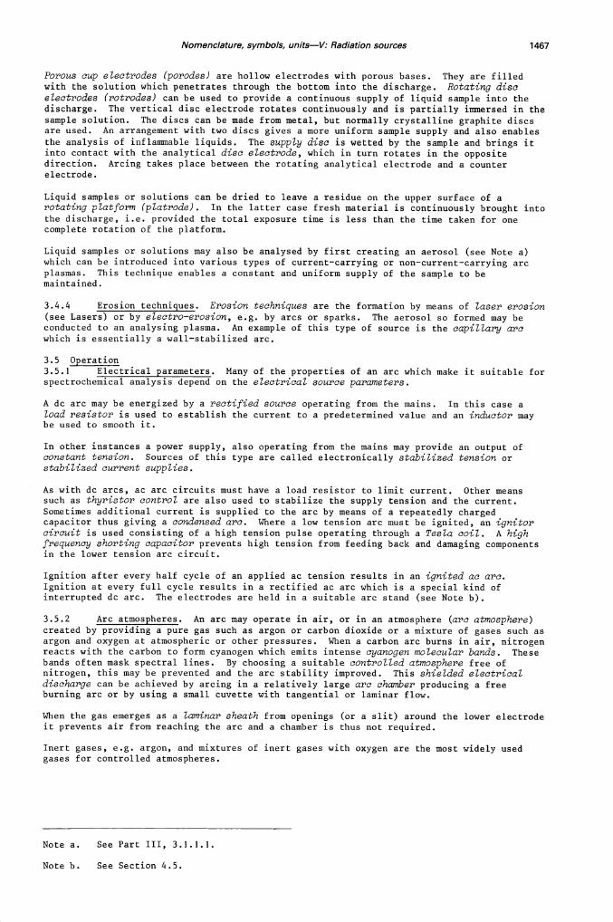
Porous cup electrodes (porodes) are hollow electrodes with porous bases. They are filledwith the solution which penetrates through the bottom into the discharge. Rotating discelectrodes (rotrodas) can be used to provide a continuous supply of liquid sample into thedischarge. The vertical disc electrode rotates continuously and is partially immersed in thesample solution. The discs can be made from metal, but normally crystalline graphite discsare used. An arrangement with two discs gives a more uniform sample supply and also enables
the analysis of inflammable liquids. The supply disc is wetted by the sample and brings itinto contact with the analytical disc electrode, which in turn rotates in the oppositedirection. Arcing takes place between the rotating analytical electrode and a counterelectrode.
Liquid samples or solutions can be dried to leave a residue on the upper surface of arotating platform (platrode). In the latter case fresh material is continuously brought intothe discharge, i.e. provided the total exposure time is less than the time taken for onecomplete rotation of the platform.
Liquid samples or solutions may also be analysed by first creating an aerosol (see Note a)which can be introduced into various types of current—carrying or non—current—carrying arcplasmas. This technique enables a constant and uniform supply of the sample to bemaintained.
3.4.4 Erosion techniques. Erosion techniques are the formation by means of laser erosion(see Lasers) or by electro—erosion, e.g. by arcs or sparks. The aerosol so formed may beconducted to an analysing plasma. An example of this type of source is the capillary arcwhich is essentially a wall—stabilized arc.
3.5 Operation3.5.1 Electrical parameters. Many of the properties of an arc which make it suitable forspectrochemical analysis depend on the electrical source parameters.
A dc arc may be energized by a rectified source operating from the mains. In this case aload resistor is used to establish the current to a predetermined value and an inductor maybe used to smooth it.
In other instances a power supply, also operating from the mains may provide an output ofconstant tension. Sources of this type are called electronically stabilized tension orstabilized current supplies.
As with dc arcs, ac arc circuits must have a load resistor to limit current. Other meanssuch as thyristor control are also used to stabilize the supply tension and the current.Sometimes additional current is supplied to the arc by means of a repeatedly chargedcapacitor thus giving a condensed arc. Where a low tension arc must be ignited, an ignitorcircuit is used consisting of a high tension pulse operating through a Tesla coil. A highfrequency shorting capacitor prevents high tension from feeding back and damaging componentsin the lower tension arc circuit.
Ignition after every half cycle of an applied ac tension results in an ignited ac arc.Ignition at every full cycle results in a rectified ac arc which is a special kind ofinterrupted dc arc. The electrodes are held in a suitable arc stand (see Note b).
3.5.2 Arc atmospheres. An arc may operate in air, or in an atmosphere (arc atmosphere)created by providing a pure gas such as argon or carbon dioxide or a mixture of gases such asargon and oxygen at atmospheric or other pressures. When a carbon arc burns in air, nitrogenreacts with the carbon to form cyanogen which emits intense cyanogen molecular bands. Thesebands often mask spectral lines. By choosing a suitable controlled atmosphere free ofnitrogen, this may be prevented and the arc stability improved. This shielded electricaldischarge can be achieved by arcing in a relatively large arc chamber producing a freeburning arc or by using a small cuvette with tangential or laminar flow.
When the gas emerges as a laminar sheath from openings (or a slit) around the lower electrodeit prevents air from reaching the arc and a chamber is thus not required.
Inert gases, e.g. argon, and mixtures of inert gases with oxygen are the most widely usedgases for controlled atmospheres.
Note a. See Part III, 3.1.1.1.
Note b. See Section 4.5.
1468 COMMISSION ON SPECTROCHEMICAL AND OTHER OPTICAL PROCEDURES FOR ANALYSIS
3.6 Spectrochemical properties and applicationsThe arc has a relatively high operating temperature and as such is suitable for theevaporation, dissociation, atomization, ionization and excitation of a wide variety ofmaterials. The radiation thus consists of molecular bands, atomic and ionic spectra and alsocontinuous radiation due to radiant particles. Samples may be mixed with or introducedtogether with additives (see Part I, Section 7.7) for controlling volatilization, transportinto the discharge region, excitation, background suppression, etc. These techniques includebuffered arcs, constant tenrperature arcs, carrier distillation arcs, seeded arcs, etc.
The free—burning dc arc consumes relatively large amounts of electrode material. It issuitable for determining trace elements in conductive samples and in non—conductive powdersamples. For larger quantities of sample, as is often necessary for the analysis ofnon—homogeneous material or for the determination of traces of volatile elements, the doublearc is useful. With this method the sample is heated by one arc and evaporated materialexcited by a second arc.
The ac arc is used mainly for metallic samples, pelleted powder samples and solutions.
Various dc arc plasmas are also successfully used for the analysis of solutions (see Sections3.2 and 3.3).
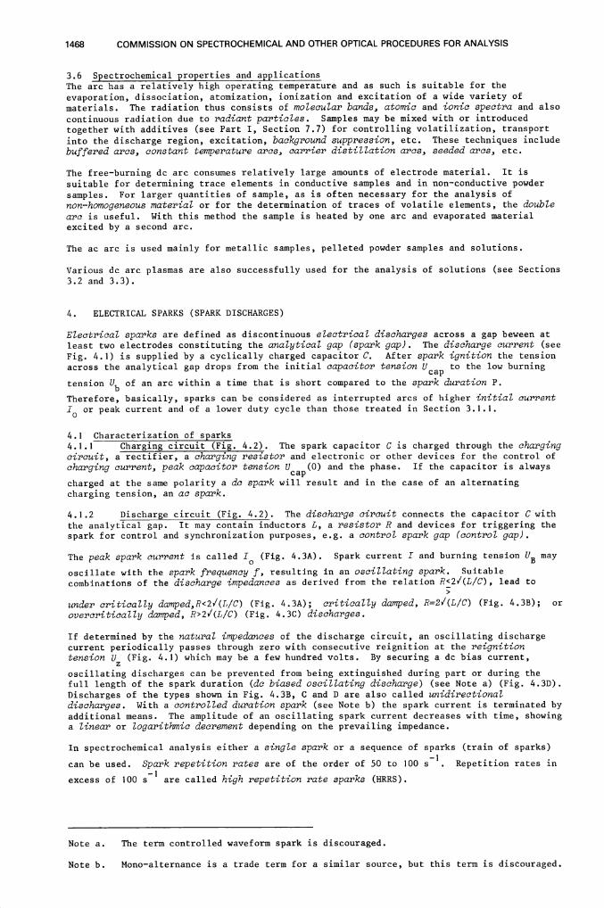
4. ELECTRICAL SPARKS (SPARK DISCHARGES)
Electrical sparks are defined as discontinuous electrical discharges across a gap beween atleast two electrodes constituting the analytical gap (spark gap). The discharge current (see
Fig. 4.1) is supplied by a cyclically charged capacitor C. After spark ignition the tensionacross the analytical gap drops from the initial capacitor tension cap to the low burning
tension Ub of an arc within a time that is short compared to the spark duration P.
Therefore, basically, sparks can be considered as interrupted arcs of higher initial current10 or peak current and of a lower duty cycle than those treated in Section 3.1.1.
4.1 Characterization of sparks4.1.1 Charging circuit (Fig. 4.2). The spark capacitor C is charged through the chargingcircuit, a rectifier, a charging resistor and electronic or other devices for the control of
charging current, peak capacitor tension Ucap(O) and the phase. If the capacitor is always
charged at the same polarity a dc spark will result and in the case of an alternating
charging tension, an ac spark.
4.1.2 Discharge circuit (Fig. 4.2). The discharge circuit connects the capacitor C withthe analytical gap. It may contain inductors L, a resistor R and devices for triggering the
spark for control and synchronization purposes, e.g. a control spark gap (control gap).
The peak spark current is called I (Fig. 4.3A). Spark current I and burning tension B may
oscillate with the spark frequency f, resulting in an oscillating spark. Suitablecombinations of the discharge impedances as derived from the relation R<2/(L/C), lead to
under critically damped,R<21(L/C) (Fig. 4.3A); critically dwied, R=21(L/C) (Fig. 4.3B); orovercritically damped, R>2/(L/C) (Fig. 4.3C) discharges.
If determined by the natural impedances of the discharge circuit, an oscillating dischargecurrent periodically passes through zero with consecutive reignition at the reignitiontension Uz (Fig. 4.1) which may be a few hundred volts. By securing a dc bias current,
oscillating discharges can be prevented from being extinguished during part or during thefull length of the spark duration (dc biased oscillating discharge) (see Note a) (Fig. 4.3D).Discharges of the types shown in Fig. 4.3B, C and D are also called unidirectionaldischarges. With a controlled duration spark (see Note b) the spark current is terminated byadditional means. The amplitude of an oscillating spark current decreases with time, showinga linear or logarithmic decrement depending on the prevailing impedance.
In spectrochemical analysis either a single spark or a sequence of sparks (train of sparks)
can be used. Spark repetition rates are of the order of 50 to 100 s. Repetition rates in
excess of 100 51 are called high repetition rate sparks (HRRS).
Note a. The term controlled waveform spark is discouraged.
Note b. Mono—alternance is a trade term for a similar source, but this term is discouraged.

Nomenclature, symbols, units—V: Radiation sources 1469
A Capacitor tension UcapB : Tension across spark gap
C Current through spark gap
FIG. 4.1 : SPARK TENSION ANDSPARK CURRENT
\1\Aflf\/\,A : Undercrltlcally damped dischargeB : Critically damped dischargeC : Overcriticaily damped dischargeD DC-biased oscillating discharge
FIG. 4.3 VARIOUS CURRENT WAVEFORMS
FIG. 4.2 : SPARK GENERATORS
UcapSPARK I SPARK 2
'O
Ug
A)
B)
C)
UB -
I
/i
A)
B)
C)
0)
CHARGING CIRCUIT
VARIASLE RESISTOR
A)fT!SFORMER
B)
C)
ANALYTICALGAP
tJ SERIES IGNITIONCIRCUIT
ANALYTICALCAPACITOR GAP
I AI
A : Controlled high tension sparkgenera tar
B Medium or low tension sparkgenerator with series ignitioncircuit
C : Medium or low tension sparkgenerator with parallel igni-tion circuit
CIRCUIT
ANALYTICALGAP
A
1470 COMMISSION ON SPECTROCHEMICAL AND OTHER OPTICAL PROCEDURES FOR ANALYSIS
The analytical gap is bridged by the electrically conducting spark channel through thedischarge atmosphere. Electrode material is removed in the form of a vapour jet from thecathode. In the case of an inert discharge atmosphere electrode material is similarlyremoved from the cathode and, in other discharge atmospheres, from the anode too. Due to therandomly distributed direction of the vapour jet the vapour cloud produced in this way may bea current—carrying or a non—current—carrying plasma depending on whether it penetrates intothe current—carrying spark channel or not.
4.2 High tension sparksA high tension spark is a self—ignited spark discharge characterized by an initial capacitortension Vcap(O) exceeding the breakdown tension of the analytical gap or of a control gap.
Typical capacitor tensions range from 10 to 20 kV (see Note a). Spark energies range fromsome tenths of a joule to a few joules. Only oscillating discharges are practicallyfeasible. Due to the possible short spark duration time several sparks per half cycle of themains supply are possible.
A high tension spark generator is called an uncontrolled high tension spark generator if thebreakdown of the analytical gap determines the initiation of the discharge. In this case thecharging time constant of the charging circuit determines the number of breakdowns per halfcycle. In a controlled high tension spark generator initiation of the discharge is governedby mechanical or electrical means. Either the tension or the breakdown time can becontrolled. The tension control may be achieved by the defined breakdown tension of astationary (open or closed) control gap (auxiliary spark gap or tandem gap) in series withthe analytical gap. The time control is achieved by a triggerable stationary gap or by thephase adjustment of a synchronously rotating gap (see Note b). Irradiation of the spark gapsby UV radiation obtained from an ionization needle or a discharge lamp and a high ohmic gapresistor (Fig. 4.2A) helps to overcome breakdown jitter.
4.3 Medium tension sparksSpark discharges have to be externally initiated if the capacitor tension Ucap(O) is lower
than the breakdown tension of the analytical gap. If this tension is still significantlyhigher than the reignition tension of the analytical gap, one speaks of a medium tension
spark (see Note c). They are externally—ignited spark discharges. Ignition is accomplishedby means of a high tension ignition pulse, also called an ignition spark. Critical dampingoccurs at resistances of a few ohms. Therefore, a choice of discharges can be made, i.e.
undercritically dconped oscillating discharges, critically damped short lasting high currentsparklike discharges, and overcritically damped long lasting low current arc—like discharges(see Note d). Apart from their different range of operating parameters, medium tension sparkgenerators require an ignition circuit. The igniting high tension pulse can be introduced inseries with the applied medium tension across the gap by means of a high frequency step—uptransformer (Tesla coil) to give series ignition (Fig. 4.2B). It can also be introduced inparallel with the gap tension to give parallel ignition (Fig. 4.2C).
In multipurpose spark sources (see Note e) the ignition may be achieved by using the hightension spark generator.
4.4 Low tension sparksThese discharges are similar to medium tension spark discharges. The capacitor tension Ucap
is of the same order as the mains supply tension. To compensate for the low tension,capacitors are accordingly large so as to provide the required spark energy. The number ofoscillations per spark is small and unidirectional discharges are easily obtainable.
Note a. Other operating conditions may be as follows: 500<C<20 000 pf, 5<L<5 000 uN,50 kHz<f<1 MHz. 10 s<O<1 ms.
Note b. Terms such as interrupters or synchronous interrupter are discouraged.
Note c. Typical operating conditions for medium tension sparks are: 500<U (O)<1500 V,l'zC<25 pF, 50<L<200 pH, O,5<R<5O cl. cap
Note d. Spark frequencies of the oscillating discharges may be 2<f<20 kHz with a sparkduration of 0.2<8<2 ms. With undercritically damped sparks the number of oscillations p willbe 1<p<5.
Note e. The word multisource is not recommended.

Nomenclature, symbols, units—V: Radiation sources 1471
4.5 Spark standsThe spark stand contains the electrode holders, usually watercooled, for one or moreelectrode configurations (see Section 4.9). Provision is made optically or mechanically toalign the electrodes and to adjust the electrode gap. Universal spark stands usually have anillumination system with a projector screen. For discharges at pressures other than normalor in atmospheres other than air a spark chcsnber is employed. Such a chamber may also have aspark confiner plate or disc made of a non—conductive material such as boron nitride toconfine the spark to a definite area of a sample surface. In order to remove the evaporatedelectrode material the spark chamber is flushed by the continuous flow of the working gas.
4.6 Discharge atmospheresThe most common discharge atmospheres are air and argon. The latter is transparent to partsof the UV—spectral region where air is not. It does not react with the electrodes andpermits the application of unidirectional discharges which do not evaporate material from theanode. Small quantities of other gases may be mixed with the principal gas, e.g. hydrogenwith argon.
4.7 Discharges in vacuumHigh excitation energies may be achieved by means of spark discharges at very low pressures.These sparks are called vacuum sparks. To overcome the high breakdown tension, a very highcapacitor tension is necessary. Breakdown can be achieved at lower tension by means of a
sliding spark, which is essentially a spark along a non—conducting surface (surface spark).
4.8 Spectral characteristicsDue to the short interaction time of the sparks with the electrodes these generally remaincool. The high current density in the burning spot at the electrodes produces such a highlocal temperature that fractional distillation is significantly reduced in comparison witharc discharges. The plasma is usually considered to be in local thermal equilibrium (LTE) assoon as the initial tension across the gap has dropped to the arc burning tension. Thetemperatures and electron pressure in this period are of the same order as those of arcdischarges. Soon after breakdown the plasma is characterised by high temperatures and highelectron pressure which are responsible for a pronounced continuous spectral background. Byseparating these two phases, with the help of time—resolved spectroscopy, it is possible toimprove the line to background intensity ratios and, correspondingly, the power of detection.
4.9 Analytical proceduresSmall quantities of the sample are removed sequentially from the many burning spots producedby the numerous sparks. Although the removal of material is by thermal evaporation, matrixeffects, due to the composition and physical properties of the surface, can be reducedsignificantly by a suitable choice of operating conditions.
The surface is first conditioned during the prespark period. This is established with theaid of a prespark curve (see Note a), also called time—of—wait curve or intensity—time curve(see Part I, Section 7.6.4). The intensity—time curve is aimed at determining optimum sparkconditions for the measurement period. In many cases these conditions coincide with sparking
equilibrium and evaporation equilibrium. High energy presparking or high repetition ratepresparking may be favourable in achieving this goal by enabling sampling from a liquid(molten) or a freshly solidified surface.
Spark sources, because of their relatively high precision and accuracy, are suitable sourcesfor the routine analysis of metals, e.g. for production control purposes.
Metals can be analysed with the point—to—point configuration using two sample electrodes(self—electrodes) of the same material. The most common technique uses the point—to—planeconfiguration, i.e. a plane electrode made from the sample material with a pointed counterelectrode made from another material, which does not contain the analytical elements.Various types of samples can be analysed in the form of solutions with the help of supporting
electrodes, carrier electrodes, rotating disc or rotating platform electrodes, vacuum cup orporous cup electrodes. The copper spark and graphite spark are specific cases of supportingelectrode techniques.
Electrically non—conductive samples can also be analysed with the help of powder techniques.Powders are prepared by grinding, sometimes after fusion (isoformation), and mixing with aconductive material, e.g. graphite or metal powder. From the mixture pellets are compressedwhich then serve as self—electrodes for spark excitation. Conductive pellets may be made bypressing metal filings, drillings and shavings.
Note a. The terms spark—off, spark—off effects and spark—off curve are discouraged.
1472 COMMISSION ON SPECTROCHEMICAL AND OTHER OPTICAL PROCEDURES FOR ANALYSIS
5. RADIOFREQUENCY PLASMAS
Radiofrequency plasmas (rf plasmas) are formed in a flow of one or more gases by anexternally applied radiofrequency field. Radiofrequency covers the range 3 kHz — 300 GHz.Within this range the following frequency bands are distinguished: 0.3 — 3 MHz (MF), 3 — 30MHz (HF), 30 — 300 MHz (VHF), 0,3 — 3 CHz (UHF) and 3 — 30 GHz (SHF) (see Note a).
5.1 Inductively coupled plasmas (ICP)In i.nductively coupled plasmas the energy is transferred to the gas with the aid of aninducti.on coil (see Note b). A set of refractory tubes called the plasma torch is arrangedcoaxially with the induction coil and the plasma is formed within it and extends above it asa tail flame.
5.1.1 Oscillators. Several kinds of electrical oscillators may be used as the energysource viz: a free running oscillator where the circuit is built up by capacitors andinduction coils to give a specific frequency which depends on the value of the components.This frequency may vary as a floating frequency around its nominal value depending on theplasma impedance.
A tuned line oscillator has, instead of coils to obtain the required inductance forresonance, one or two tuned lines. The induction coil for the plasma is located in thesecondary circuit also with tuned lines. The electromagnetic coupling between the twocircuits constitutes an impedance converter to match the load or load variations.
A crystal controlled oscillator has a quartz crystal in the circuit to obtain a fixed
frequency of oscillation. A series of other stages (circuits) permits frequencymultiplication, power amplification and impedance matching (see Note c). Impedance matchingis required to minimize the reflected power, which is the power reflected back to theoscillator. The incident power is the power available at the induction coil. The couplingefficiency is the ratio of the power transferred to the plasma to the incident power.
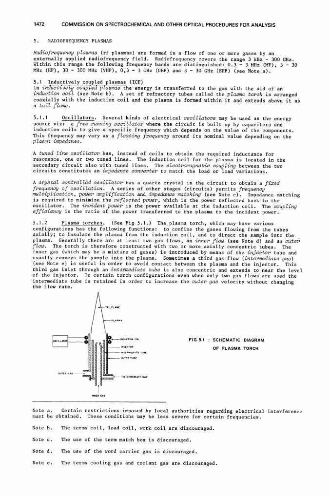
5.1.2 Plasma torches. (See Fig 5.1.) The plasma torch, which may have variousconfigurations has the following functions: to confine the gases flowing from the tubesaxially; to insulate the plasma from the induction coil, and to direct the sample into theplasma. Generally there are at least two gas flows, an inner flow (see Note d) and an outerflow. The torch is therefore constructed with two or more axially concentric tubes. Theinner gas (which may be a mixture of gases) is introduced by means of the injector tube andusually conveys the sample into the plasma. Sometimes a third gas flow (intermediate gas)(see Note e) is useful in order to avoid contact between the plasma and the injector. Thisthird gas inlet through an intermediate tube is also concentric and extends to near the levelof the injector. In certain torch configurations even when only two gas flows are used theintermediate tube is retained in order to increase the outer gas velocity without changingthe flow rate.
FIG.5.1 : SCHEMATIC DIAGRAM
OF PLASMA TORCH
Note a. Certain restrictions imposed by local authorities regarding electrical interferencemust be obtained. These conditions may be less severe for certain frequencies.
Note b. The terms coil, load coil, work coil are discouraged.
Note c. The use of the term match box is discouraged.
Note d. The use of the word carrier gas is discouraged.
Note e. The terms cooling gas and coolant gas are discouraged.

Nomenclature, symbols, units—V: Radiation sources 1473
The following nomenclature system is recommended for indicating the gases or gas mixturesrelative to the tubes from which they emerge. The gas emerging from the injector is listedfirst. Gases emerging from the other tubes are then noted separated by a hyphen (—) andmoving outwards, i.e. injector gas — intermediate gas — outer gas. Gas mixtures areindicated by a ratio (I) with the major component indicated as the nominator.
Examples: 1) A two tube torch using argon for both flows: Ar — Ar2) A three tube torch using argon inner, argon intermediate,
and nitrogen outer: Ar — Ar — N23) A three tube torch using a gas mixture of argon mostly and
some oxygen for the inner flow, argon for the intermediateflow and a mixture of nitrogen mostly and argon for theouter flow: Ar/02 — Ar — N2/Ar
If it is desired to state the gas mixture ratio this is done in brackets e.g. (1:1).
Example: Ar/02(3:1) — Ar — N2/Ar (1:1)
The velocity of the inner gas must be sufficiently high to pierce the plasma (see Note a) butnot too high to reduce the transit time of the analyte and thus increase the residence timeof the atoms, ions, etc. in the excitation zone.
An ICP can be initiated either with the use of a conducting rod inserted into the torch atthe inductor level or by means of an electrical discharge to produce ions created by a Teslacoil.
5.1.3 Plasma parameters. The type and intensity of spectral lines observed in theobservation zone of the plasma depend on several plasma parameters: the height, width andposition of the observation zone, usually related to the top of the induction coil, the innergas and outer gas flow rates, the intermediate gas flow rate (if any), the incident power of
the plasma generator and the coupling efficiency, the physical state of the sample (gas,powder or aerosol particles), the sample uptake rate (or rate of liquid consumption), theefficiencies of nebulization, aerosol transport, desolvation, volatilization and atomization(see Part III, Section 3.1.2), and the characteristics of the spectral lines chosen. In acomplex matrix, the line intensities of all analyte elements are usually measured using theoperating parameters normally used for the sample solution. This requires the selection ofconromise conditions which may not be optimum for all elements.
5.2 Capacitively coupled plasmas (CCP)A capacitively coupled plasma may be obtained by energy transfer through capacitive coupling.Coupling is obtained by applying a high frequency tension to a capacitor which consists of acylindrical (or coiled) electrode and a coaxial conductive (sometimes pointed) hollow axialelectrode. The torch consists of a fused silica tube, placed coaxially between the twoelectrodes. The carrier gas emerges from the inner electrode through holes drilleddiagonally or radially. The plasma forms at the tip of this central electrode giving rise towhat has been called a brush discharge (see Note b).
It is possible, especially when using higher radio—frequencies, to remove the outer electrodeand to have the central electrode discharge into air.
5.3 Microwave plasmasThe initiation procedure and the sustaining, thermal and excitation properties of microwaveplasmas are different to those plasmas considered in 5.1 and 5.2. The frequency range ofthese sources is above 300 MHz with a frequency of 2,450 GHz being the most common for legalreasons.
Generally, the microwaves are emitted via the antenna of a magnetron and transmitted by means
of a waveguide. Depending on the power, the energy is coupled directly to the cavity (or anyother device) or by means of a coaxial cable. Argon, helium and nitrogen are the plasma
gases usually used.
5.3.1 Loaded line microwave plasmas (LLMP). The loaded line microwave plasma device,incorrectly called capacitive microwave plasma (CMP), consists of a coaxial conductorconnected transversely to the wave guide or to the coaxial cable. Usually a central pointedelectrode of the conductor is used to conduct both the aerosol and the plasma gas. Plasmaformation at atmospheric pressure takes place at the tip. Variable short circuits are usedto adjust the length of the waveguide and to match impedance variations of the plasma.
Note a. The term dynamic range is sometimes used but should be discouraged.
Note b. This term is historical and also applies to the single electrode microwave
discharge source.
1474 COMMISSION ON SPECTROCHEMICAL AND OTHER OPTICAL PROCEDURES FOR ANALYSIS
5.3.2 Microwave induced plasmas (NIP). The most common configurations for MIPs arecoaxial cavities (working in 1/4 or 3/4 wavelength modes), the tapered rectangular cavities,the antenna, the cylindrical cavities, the slow wave structures, the transverseelectromagnetic mode TM010 cavities, the surface wave propagation structures and the slabline cavities.
The plasma is usually generated in a silica tube through which both the plasma gas and theaerosol gas are flowing. Impedance variations are matched either by tuning the resonantcavity by means of stubs or by modifying the size of one dimension of the structure. Most ofthe time, these plasmas are produced at atmospheric pressure but may also be produced atlower pressure, still with flowing gases.
In some cases, a sealed silica container (tube) or quartz vessel at reduced pressure andcontaining a small portion of the sample to be analysed is introduced in the resonant cavity.Alternatively, the silica tube may contain an element or elements such that the source can beused as a primary source (e.g. for AAS and AFS). These MIPs are called electrodelessdischarge sources and are often used as primary radiation sources for AAS and APS.
5.4 Analytical featuresPlasma radiation sources are used mainly for the analysis of liquid samples and analyticaltechniques and terms are similar to those described in Parts I and III. Sa'irple solutions arenebulised and the aerosol introduced continuously or discretely. Liquid slurries containingundissolved powders, suspensions, emulsions and dry powders have also been introduced withthe inner gas. The measuring system is adapted to the sample introduction system e.g. steadystates instantaneous (short time) or integrated measurements. Radiation intensity isaffected by the residence time of the atoms in the excitation region of the plasma. Spatial
distribution interferences may be observed.
NIP's are also useful for the analysis of gaseous samples e.g. as detectors in gas
chromatography.
Important techniques for determining the analyte concentration include the analytical curvetechnique, bracketing using reference solutions or reference materials. An internalreference line is often measured when a reference element has been added to the solution.The analytical addition technique as described in Part III Section 4.2 is also used.Background radiation often necessitates the use of background correction. Plasma sources aregenerally characterised by their extensive analytical concentration range and wide elemental
coverage.
6. LASERS
In this section the laser will be considered as a source of thermal energy and not as aprimary source of highly monochromatic coherent radiation.
Radiation from a laser source is emitted with a very small angle of divergence. Its radiantintensity, i.e. its radiant power per solid angle can be very high. By focusing laserradiation with a focusing lens or a focusing mirror of focal length f onto a target, i.e. thesurface of a sample, a high irradiance in a small focal spot is obtained. This is sufficientto cause vaporization and atomization of materials, irrespective of their physicalproperties, e.g. boiling temperature. The laser produced vapour cloud which is produced maycontain enough neutral atoms in the ground state for atomic absorption analysis. If thelaser—produced vapour cloud is sufficiently hot to radiate in the optical spectral region, itcan be used directly as an excitation source for emission spectroscopy. Additional forms ofexcitation may be used to increase the spectral radiance of the vapour or to improve the
analytical line—to—background intensity ratios.
6.1 Characterization of lasersBasically, a laser consists of an active medium in which, by optical pumping or electricalexcitation (whichever is applicable), population inversion of energy levels, and hencestimulated emission of radiation, may be obtained. Laser action or lasing may either becontinuous, i.e. continuous wave (cw—operated) or in the form of a single laser pulse or
sequence of laser pulses.
The active medium is placed in the laser resonator which has two mirrors in either confocalor parallel configurations. The radiant energy leaves the resonator in the form of a laser
beam which, in theory, may be coherent temporally and spatially. By phase coupling and modelocking specific wavelengths may be selected and coherence improved.
Sources which lase continuously may be characterized by the pumping or exciting power (orcurrent strength), the laser output power, the wavelength and the angle of divergence (thetransversal mode).
Nomenclature, symbols, units—V: Radiation sources 1475
Pulsed laser sources may, in addition, be characterized by the duration of the punrpi.ngperiod, the laser output energy, the repetition rate and temporal spacing of the laser outputpulses. The individual pulses are characterized by the peak pulse power, the pulse energyand the pulse duration. The laser resonator can also be considered as a resonant cavitywith, theoretically, an infinite number of possible eigen—frequencies, which are commonlydescribed by their modes, i.e. transversal as well as longitudinal.
6.2 Solid state lasersThe active medium is usually a rod consisting of a host material which is doped with a
laser—active substance. Examples are Nd—glass, i.e. glass doped with neodymium; Nd3: lAG,i.e. yttrium aluminium garnet doped with neodymium; or ruby, i.e. aluminium oxide doped withchromium. The active medium is placed in the punrping cavity where it is illuminated by thepunrping lamp. The wavelength of the emitted radiation is either in the visible or nearinfra—red spectral region.
6.2.1 Continuous wave operation (cw—operation). Continuous wave operation is onlyfeasible if the pump power required to exceed the lasing threshold, is low. This may be
accomplished by optically pumping a Nd3: YAG rod by means of a tungsten—halogen lamp.
6.2.2 Free—running operation. Under free—running operation the laser output ischaracterized by the emission of a large number of irregular and incoherent radiation pulsesof short duration called laser spikes. Typical spike peak power is of the order of severalkilowatt and the total duration of the laser action is of the order of some tenths of amillisecond.
6.2.3 Q—switched operation. A shutter called a Q—switch, is inserted in the laserresonator to obstruct or impede the path of light during part of the pumping period. It mayallow more energy to be stored in the active medium by population inversion. When theshutter opens sufficiently fast, the Q (i.e. quality factor) of the resonator and hence theinternal oscillation amplitude rises rapidly, resulting in the emission of a short singlepulse, also called giant pulse, of high power (typically of the order of several MW).Shutters which do not open fast enough may cause the emission of several spikes of mediumpower (100 kW). This action is called semi—Q—switched. Q—switched operation may beinitiated several times during a pumping period. Many types of Q—switches are used, e.g.saturable dye—switch consisting of a bleachable substance which may be transparent or opaqueto the laser radiation, depending on the degree of irradiance, electro—optical shutters,which make use of the quadratic electro—optical effect (Kerr cell) or of the linearelectro—optical effect (Pockels cell), mechanical shutter such as a rotating disc, a rotatingmirror or a rotating prism, magneto—optical shutters, which make use of the Faraday effectand acousto—optical shutters, which temporarily cause diffraction or refraction in the laserresonator. The latter type of Q—switch is capable of producing an equidistant series ofspikes of medium power.
6.3 Other lasers6.3.1 Liquid lasers. Liquid lasers having suitable host solutions doped with neodymiumor dyes as the active medium, can give performances similar to solid state lasers. With dyelasers a wide variety of wavelengths is available.
6.3.2 Gas lasers. Electrically excited (i.e. low pressure electrical discharge) laserscan be operated in the various modes described previously. With pulsed gas lasers, a veryhigh laser output can be obtained e.g. the CO2 laser at a wavelength of 10.6 pm.
6.4 Vaporization and atomization
Vaporization takes place from an area of the sample on which the laser radiation is focused.
A crater is formed during evaporation characterized by the crater diameter, the crater depthand the crater shape. The crater diameter should not be confused with the focal spotdiameter which may be larger or smaller than the crater diameter. However, the diameter ofthe focal spot influences the crater diameter. The theoretical ultimate focal spot diameteris diffraction limited and usually cannot be achieved due to imperfections of the activemedium.
The vaporized material leaves the target in a vapour stream or jet forming the laser plumewhich may consist partly of free atoms. To prevent unwanted chemical reactions(e.g. oxidation) of the plume with the surrounding air, a sample chamber filled or flushedwith a suitable inert gas is often used.
6.5 Lasers as atomizers for atomic absorption spectroscopyVaporized material which is sufficiently atomized can be utilized for atomic absorptionmeasurements. Better analytical results can often be obtained if the material contained inthe plume is further atomized by means of a flame or a furnace.

1476 COMMISSION ON SPECTROCHEMICAL AND OTHER OPTICAL PROCEDURES FOR ANALYSIS
6.6 Laser atomization and excitation for use in optical emission spectroscopy
Lasers of high power output, e.g. Q—switched lasers, may be capable of producing atomicvapour at such high temperatures that appreciable optical radiation is generated, thus actingas a one—step excitation source for emission analysis. Due to the initial high pressure, theanalysis lines may be broader and show more self—absorption than in other excitation sourcessuch as arcs and sparks, thus restricting their useful analytical range.
6.7 Optical emission spectroscopy with laser atomization and additional excitationThe laser—produced plume can be excited by a supplementary source. [n this two—stepatomization—excitation procedure, the radiance of the analysis lines can be increased and theline—to—background intensity ratios can be improved.
6.7.1 Spark cross—excitation. If the laser plume is allowed to enter a spark gap acrosswhich a medium tension spark discharge takes place, additional atomization and excitation arepossible. This is called spark cross—excitation. The spectra produced in this way areessentially those of a medium tension spark. Triggering of the auxiliary discharge may beeffected by the laser plume itself or by external means.
6.7.2 Electrodeless excitation. Additional excitation by means of an electrodelessdischarge results only in the production of a spectrum originating from the material of thelaser—produced plume and of the surrounding atmosphere. Contamination from auxiliaryelectrodes can thus be avoided.
6.8 Analytical applicationsBecause lasers are non—electric excitation sources, they can be applied to the analysis of a
very large variety of electrically conducting as well as non—conducting substances.
Analyses may be improved by selecting a suitable gas atmosphere or by applying time— and/orspace—resolving techniques. Special sample preparation techniques may also be useful.
6.8.1 Local analysis with lasers. The possibility of vaporizing material from apre—determined small area of a sample makes laser atomization suitable for local analysis(see Note a). This is also called in situ microanalysis.
As small crater dimensions are of primary importance for obtaining high spatial resolution onthe sample, the laser output energy has to be restricted. This makes additional excitationalmost obligatory.
6.8.2 Microanalysis with lasers. Microanalysis is possible if a microsample can first beconcentrated into a small volume and positioned onto a suitable support in such a way that alocal analysis can be carried out. Additional excitation is also necessary.
6.8.3 Macroanalysis with lasers. Homogeneous samples of almost any kind can be analysedby laser atomization. High energy and high power single laser—shot operation should be used.This leads to the vaporization of sufficiently representative amounts of sample material.Alternatively, scanning a part of the sample area by using a number of laser shots of lowerenergy and power form the basis of scanning laser analysis. High precision may be obtainedby the super—position of a sufficiently large number of laser shots. Direct excitation issufficient for the determination of the major constituents, but additional excitation may benecessary for the determination of trace elements.
7. LOW PRESSURE ELECTRICAL DISCHARGES (LPED) (see Note b)
Low pressure electrical discharge sources (see Note c) are radiation sources in whichradiation is produced by electrical discharges in gases at low pressures, i.e. pressures from
to Pa (see Note d). Atoms or molecules of the samples to be analysed are present orare introduced into the discharge. Usually one of the noble gases such as argon or neon isused, but mixtures of these gases and/or small quantities of diatomic or polyatomic gases mayalso sustain a discharge. Such a gas is called the carrier gas, this term being preferred to
fill gas or discharge gas.
Note a. The use of the term laser microprobe analysis is discouraged.
Note b. The term low pressure gas discharge (LPGD) is commonly used, but is not recommendedbecause it could mean the discharge of a gas instead of an electrical discharge in a gas.
Note c. Source is the preferred term when a low pressure electrical discharge is used asthe sampling source. The term lamp usually indicates a primary source that generally ispermanently sealed, e.g. hollow cathode lamps for atomic absorption spectroscopy (see Terms,units and symbols for the description of processes common to all radiation sources andPart III, Section 3.2).
Note d. See Section 2.3.3, footnote.

Nomenclature, symbols, units—V: Radiation sources 1477
Generally the sample is introduced by making it form a part of the cathode and, as a resultof ionic bombardment and atomic bombardment of its surface, material is removed by the
process of cathodic sputtering and/or thermal evaporation. This material enters the plasmaand atoms are excited to produce characteristic radiation. If the sample is already in agaseous form, it may be introduced into the discharge separately or mixed with the carriergas.
7.1 Terms relating to the processesThe processes of LPED are explained in terms of a classical discharge chamber of cylindricalshape in which two plane electrodes of conductive materials are separated by a distance 1(see Fig. 7.1). The pressure, tension and current are three controllable and variableparameters which may be interdependent (pressure—tension—current relationship).
The vessel may be sealed or it may be flushed (pumped) continuously.
Continuously flushed systems, also known as dynamic or pumped systems, occur in those sourceswhere the carrier gas is being replaced continuously and the flow controlled either by meansof a needle valve or a gas—restricting orifice.
C
CATHODE
ATHODEGLOW
!GLOW
NEGATIVE
POSITIVE COLUMN
'FTIONSANODE GLOW
ANODE
BRIGHT REGION
DARK REGION
FIG. 71: SCHEMATIC DIAGRAM OF A LOWPRESSURE ELECTRICAL DISCHARGEBETWEEN PLANE ELECTRODES
FARADAYDARK SPACE
CROOKSDARK SPACE
If the vessel is evacuated to high vacuum, the carrier gas allowed to fill it to apredetermined low pressure, and tension applied to the electrodes from a dc source, a currentwill flow. This current will initially be very small, but once the tension reaches thebreakdown tension Ubr a higher current, depending on the characteristics of the external
circuit, will flow between the anode and cathode.
Simultaneously with the flow of current a glow discharge with specific characteristics willdevelop between the electrodes.
7.1.1 Radiation. The spatial distribution of radiation moving axially from the cathodetowards the anode, has specific luminous characteristics.
At the cathode a narrow dark space (Aston Dark space) (see Note a) is seen, adjacent to whichis a slightly luminous layer. This is called the cathode glow. Next a non—luminous volumeknown as the cathode dark space (or Crookes (Hittorf) dark space) is seen, which is verydistinct from the highly luminous negative glow. The negative glow tails off into theFaraday dark space, followed by another luminous region. This luminous region, called thepositive column, may have several alternating or moving, dark and luminous regions. Shouldthe positive column have structure, these luminous and dark regions are called striations.Near the anode another dark space occurs (the anode dark space). The anode itself is usuallycovered with a slightly luminous sheath called the anode glow.
If the distance 1 is changed while maintaining constant pressure and tension, the axiallengths of the zones from the cathode to the positive column remain unaltered. However, thelength of the positive column will change.
If the anode is brought so close to the cathode that it enters the negative glow, the
positive column may disappear completely, but all other parameters of the discharge remainalmost the same.
The dimensions of the negative zones are dependent on the pressure, the shape and area of thecathode, and the current.
Radiation processes in the chamber depend on the interaction of electrons with atoms and ionsof the carrier gases or analyte atoms and analyte ions.
Note a. In all electrical terminology the dark spaces were named after early pioneers inresearch on electrical discharges.

1478 COMMISSION ON SPECTROCHEMICAL AND OTHER OPTICAL PROCEDURES FOR ANALYSIS
7.1.2 The discharge. At a tension less than the breakdown tension, residual ionization,which is present in any gas, results in a dark (non—luminous) discharge. At the breakdowntension electrons are released from the cathode at their ejection energy (1 eV). Due tothis low energy these electrons are unable to transfer their energy on collision to theexcitation of atoms (Aston dark space). While being accelerated through the cathode fall
region, the region of high potential gradient, they gain enough energy to excite atoms bycollision. This results in the luminous cathode glow. Other electrons acquire energies inexcess of the excitation energy and are rapidly accelerated into the cathode (Crookes) darkspace. Here they collide with neutral atoms of the carrier gas causing ionization.
e + A -'- A+ + 2e
This process is called electron multiplication. The electron population consists of twodistinct groups — fast and slow electrons. Fast electrons are those initiated at or near thecathode and slow electrons are those created by secondary ionization processes.
Slow electrons are only partially accelerated by the cathode fall potential and havesufficient energy distribution to cause excitation of gas atoms in the highly luminous
negative glow.
Fast electrons impart their energy through collisions of the first kind to cause ionization.Due to the weak potential gradient in the positive column they are unable to achievesufficient energy to cause excitation.
Partial acceleration and the subsequent loss of energy through excitation, which may takeplace repeatedly, causes the striations in the positive column.
A Penning gas mixture consists of a rare gas containing atoms of another gas possibly at verylow concentrations. The foreign atoms have an ionization potential V. which is lower orequal to the metastable potential (Vt) of the parent noble gas.
ion
The Penning effect in a Penning gas mixture is the ionization by charge transfer (chargeexchange) during collision between a metastable atom and a neutral atom which decreases the
average energy to form an ion pair, e.g. Cu +Armeta
= Cu+ + Ar + e. In a glow discharge
this results in an increase of the ionization coefficient (Townsend first coefficient), adecrease in breakdown potential and a lowering of the cathode fall potential.
7.1.3 Cathodic sputtering. Ions from the Crookes (Hittorf) dark space are acceleratedtowards the cathode. Most of the positive ions impinge upon the cathode and by momentumtransfer impart their energy in a succession of binary collisions to atoms in the surfacelayer of the cathodic material. Other ions in their movement towards the cathode becomeneutralized, either by capturing free electrons in the space charge near the cathode or bycharge transfer with other atoms, but still maintain their momentum towards the cathode.A large portion of these atoms will impart their energy to the cathode. Some particles enter
the crystal lattice by a process called channelling. In this way they penetrate relativelydeeply into the solid state crystal lattice, releasing their energies within the crystal.Part of the energy released below the surface is transported to the topmost monolayer by wayof collisional chains and gives rise to the ejection of atoms from the sites where thecollision chains terminate. Ejected atoms include atoms of gases absorbed onto the surfaceof the cathode. The whole process is called cathodic sputtering.
The sputtering yield S5 is the number of sputtered atoms released per incident ion. The
sputtering rate q5 is the amount of material sputtered per unit time.
7.1.4 Clean up. Clean up is a process caused by sputtering, trapping (or adsorbing)metallic atoms, gas atoms or molecules on the walls of the vessel or anode. This has theeffect of reducing the gas pressure in sealed lamps, and may be useful for cleaning up or
gettering unwanted gases.
7.2 Types of glow dischargesIf the discharge vessel shown in Fig. 7.1. and referred to in this section is kept at aconstant pressure of about 100 Pa and the applied tension increased while the current is
measured, the tension—current relationship enables discharges with specific dischargecharacteristics to be identified, viz.
7.2.1 Normal glow discharge. The normal glow discharge is characterized by a constant
burning tension for a range of currents from '1O — ,io2 A. The current density at any
point at the cathode remains constant, but the cathode area is not fully covered by the glow(see Note a). As the current increases, more of the cathode becomes covered by the glow.
Note a. The onset of the normal discharge is highly dependent on the shape, size andmaterial of the electrodes, the current carrying gas and the impurity gases and to a lesserextent, on the shape of the containing vessel.
Nomenclature, symbols, units—V: Radiation sources 1479
7.2.2 Abnormal glow discharge. After the negative glow fully covers the cathode area, afurther increase of current results in a rise in the burning tension and thus in the currentdensity. This is an abnormal glow discharge. The tension and current rise almost linearly
for a current change of 5 x 10 — 5 x 10 1A. After this current is reached the ionbombardment on the cathode is so energetic that thermal effects cause the discharge to changeto an electric arc (see Section 3).
An abnormal glow discharge also results when the area of the cathode in the original normaldischarge is reduced. This is called a restricted glow discharge or a restricted abnormalglow discharge. This occurs for example when an annular anode which restricts the cathodearea is placed within the cathode fall region of the discharge. Differential pumping of thegap to a higher vacuum than the discharge region, enlarges the cathode fall in that region.
The restricted (abnormal) discharge should not be confused with the constricted glowdischarge. In the constricted discharge the radius of the vessel between the anode andcathode is reduced to the order of one free ionic path length. Fast electrons from thecathode reach the anode and produce X—rays which together with fast positive ions releasesecondary electrons from the cathode.
7.2.3 Spray discharge. The spray discharge develops when a very thin insulator orsemi—conducting surface, (e.g. an oxide layer) covers the cathode surface. A dischargewithout a dark space develops. The cathode fall is lower and a much higher tension isrequired to sustain the discharge.
7.3 Terms and description of sources7.3.1 Arc lamps. Certain spectral radiation sources in sealed vessels operate, at lowpressures, as arcs. They are known as arc lamps. These arcs are sustained mainly as aresult of thermal processes and are characterized by a cathode fall potential which is muchlower than a glow discharge; a thinner cathode glow region, and high current densities. Thespectrum emitted is due to the discharge gas and the cathode material. Atomic line spectraare dominated by transitions of the lower energy levels of neutral atoms.
The electrodes of low pressure arc lamps (102 — 10 Pa) may have supplementary heating tostrike initiate the arc and constricting devices to increase the positive column current
density resulting in increased spectral radiance.
Supplementary electrodes are often coated with a material or mixtures of materials having lowwork function (e.g. tn—oxide layers) to reduce the tension at which the arc will strike.
Low pressure arcs usually require tensions between 300 and 600 V to strike, but the operatingtension falls once the arc is initiated.
Metal vapour arc lamps (metal vapour arcs) usually contain metals with low melting points andlow ionization potentials. These include the alkali metals, some alkaline earths, and metalssuch as mercury and cadmium. Mercury, having a high vapour pressure does not usually requiresupplementary heating of electrodes.
Radiation comes mainly from the arc column and the electrodes may be screened off by means ofshields. The intensity of radiation may also be enhanced by restricting or confining thedischarge.
High pressure arc lamps (>100 kPa) give broadened spectral lines, but have high intensitiesand heavy continuous backgrounds. Low pressure arc lamps give lower intensities, but havenarrower spectral lines.
Metal vapour lamps usually operate on alternating current so that anode and cathodeconstruction can be identical. Argon and neon are the most commonly used carrier gases.
Arc lamps are used as primary spectral radiation sources, e.g. for atomic absorptionspectroscopy, calibration of spectrometers and spectrographs, and for lighting purposes.
7.3.2 Geissler lamps. Geissler lanrps are glow—discharge sources operating in the normalmode. They have a capillary tube between the annular anode and cathode to constrict thedischarge of the positive column. These sources are either continually flushed or sealed.The excitation mechanisms of Geissler sources involve atoms being excited in the positivecolumn. Constriction results in the availability of fast electrons to cause ionization ofthe carrier gas.
These sources are mainly used for gas analysis. Impurity gases are bled into the vacuumsystem. Spectra are viewed end—on through the annular anode. Molecular spectra may also bemeasured if the capillary tube between the electrodes is not too narrow (see 7.2.2).
1480 COMMISSION ON SPECTROCHEMICAL AND OTHER OPTICAL PROCEDURES FOR ANALYSIS
7.3.3 Hollow cathode sources. The hollow cathode cource (hollow cathode lamp (HCL)) hasa cylindrically shaped cathode, one end of which may be closed.
In a normal hollow cathode the ratio of length to diameter is 1. Open—ended hollow cathodeshave both ends open.
The hollow cathode discharge may operate as a normal or an abnormal discharge, depending onthe dimensions of the cathode, the carrier gas, and the cathode material. More complex ion,electron and photon processes take place in the discharge than in a plane cathode glowdischarge (see Section 7.3.4). This gives rise to profuse cathodic sputtering and highspectral line intensities. When used as sampling sources they are usually continuallyflushed to remove impurity gases generated from the sample in the cathode.
In the cold hollow cathode source the cathode may be cooled externally (e.g. by air, water or
liquid nitrogen).
The result is that thermal effects on the cathode surface are kept to a minimum even at highcurrent densities. Most material is removed from the cathode by cathodic sputtering. Highintensities and narrow spectral lines are obtained.
Hot hollow cathode sources are designed to enable the temperature of the cathode to riseappreciably and to cause material to be vaporized by thermal heating and sputtering. Thetemperature may be so high that the material in or on the cathode is liquid or molten. Thismaterial may be a sample introduced into the cathode.
Sealed hollow cathode lamps are used as primary sources for atomic absorption spectroscopy,because of their relatively intense radiation, narrow spectral lines, and stable emission(when operated from current—stabilized supplies).
High intensity hollow cathodes (also called high brightness (see Note a)) are made byshielding the cathode lip or reducing its diameter and thus increasing the current and iondensities. This partly inhibits the emission of sputtered material and may result in ahigher atomic line intensity per unit current.
With boosted hollow cathodes it is possible to increase the intensity of the primarydischarge by introducing a secondary discharge via one or two supplementary electrodes. The
electrodes may be placed so that the supplementary discharge (mainly its positive column)runs across the front of the cathode or through an open—ended cathode. The supplementaryelectrodes are made from or are coated with material having a low work function, so as toenable the supplementary discharge to be of lower tension than the primary (glow) discharge.
They may also be resistively heated. Supplementary discharges are generally aimed atenhancing the resonance spectral lines to obtain higher intensities and reduced
self—absorption effects.
Intensity modulated hollow cathode lconps are widely used in atomic absorption and atomic
fluorescence spectroscopy.
Hollow cathode sources are used as sampling sources for the emission analysis of smallquantities of materials or where material should not be lost, e.g. precious metals (gold) orradioactive materials. Elements with high excitation potentials may be excited in a hollowcathode discharge to give stable and narrow line spectra.
Hollow cathode sources have been used as high resolution sources, e.g. for isotopic analysis,vacuum ultra—violet studies, gas analysis and the analysis of non—metals. They are also wellsuited as sample sources for gas analysis.
7.3.4 Plane cathode glow—discharge sources. Plane cathode glow—discharge sources(see Note b) operate under abnormal glow—discharge conditions. The sample, which must have aplane surface, is made the cathode of the discharge. Restriction of the area to be sputteredcan be achieved by several means, e.g. by using an annular anode (see Section 7.2.2) whichfaces the sample surface with such a small gap (100 — 200 iim), that no short circuitdischarge can occur. Another device for restricting the discharge is a restrictor plate madefrom an insulating material and placed close to the cathode. With the first system, twovacuum pumps are used. One is a differential pump to evacuate the gap (anode—gap) and theother is used to evacuate the chamber and maintain the discharge pressure while the lamp iscontinually being flushed with fresh carrier gas. A single pump may also be used.
Note a. High brightness or hi—brightness are not recommended.
Note b. The Grimm glow—discharge source is an example of this type of source.
Nomenclature, symbols, units—V: Radiation sources 1481
The discharge is essentially abnormal and tensions of up to 2 kV may be used. The gas flowflushes away residual or absorbed gases released from the cathode. The high operatingtensions enable profuse sputtering to take place, even from poorly conductive materials.
Two of the three parameters, current, tension and pressure generally are variable, while thethird is kept constant.
Sputtering takes place in much the same way as in any glow discharge, except that theabnormal conditions allow higher tensions resulting in much more energetic sputtering andexcitation. The flow of gas across the sample surface is radially away from the surface sothat atomic species, including gas released from the sample, are swept away. This results inan optically thin plasma with little self—absorption of lines.
It is possible to introduce supplementary electrodes to cause a secondary discharge and, byso doing, to enhance the sample spectra. This discharge may be modulated and by using atuned amplifier measuring system only the enhanced radiation is measured. This lamp iscalled a boosted output glow—discharge source.
Glow discharges may be operated under the influence of an external magnetic field. Suchmagnetic field glow—discharge sources have either a permanent magnet or an electromagnetplaced in such a way that ions and electrons are influenced by the magnetic field to achieveenhanced intensities and more profuse sputtering.
If in such a discharge source one or more supplementary electrodes are introduced to modifythe discharge it is called a boosted magnetic field glow discharge source.
7.4 Analytical proceduresLow pressure electrical discharge sources are used for many different types of analysis,particularly of metals. Because the discharge takes place in closed vessels, these sourcesare appropriate for the analysis of radioactive material.
Low pressure electrical discharge sources may be used in mass spectroscopy for the provisionof ions.
The plane cathode glow—discharge source is well suited for the analysis of metals. It mayalso be used for the analysis of non—conducting powders by mixing them with conductingpowders such as copper and silver and pressing a solid pellet from the mixture.
Generally solutions are not analysed directly by low pressure electrical dischargesources.

1482 COMMISSION ON SPECTROCHEMICAL AND OTHER OPTICAL PROCEDURES FOR ANALYSIS
8. INDEX OF TERMS
abnormal glow discharge (Section 7.2.2)absorb (Section 2)absorption (Section 2.3.5)absorption profile (Section 2.4.5)acoustical shock—wave sifter system (Section 3.4.3)acousto—optical shutter (Section 6.2.3)active medium (Section 6.1)aerosol (Section 3.4.2)
agglomeration (Section 3.4.3)alternating current (Section 3.1)alternating current (ac) arc (Section 3.1.1)alternating current (ac) spark (Section 4.1.1)analytical addition technique (Section 5.4)analytical concentration range (Section 5.4)analytical curve technique (Section 5.4)analytical electrode (Section 3.4.1)analytical gap (arc gap) (Section 3.4.1)analytical gap (spark gap) (Section 4)angle of divergence (Section 6)annular anode (Section 7.2.2)anode dark space (Section 7.1.1)anode glow (Section 7.1.1)anodic vaporization (Section 3.4.1)arc atmosphere (Section 3.5.2)arc chamber (Section 3.5.2)arc column (Section 3.1.2)arc gap (Section 3.4.1)arc lamp (Section 7.3.1)arc—like discharge (Section 4.3)arc—stand (Section 3.4.1)Aston dark space (Section 7.1.1)atomic bombardment (Section 7)atomic fluorescence (Section 2.3.5)atomic spectrum (Section 2.2.1)atomization (Section 2)
auxiliary discharge (Section 6.7.1)auxiliary spark gap (tandem gap) (Section 4.2)average gas pressure (Section 2)axial electrode (Section 5.2)
background correction technique (Section 5.4)background radiation (Section 2.2.4)background suppression (Section 3.6)band spectra (Section 2.2.3)biased oscillating discharge (Section 4.1.2)binary collision (Section 7.1.3)black—body radiation (Section 2.2.3)bleachable substance (Section 6.2.3)bleed (Section 7.3.2)blow—in procedure (Section 3.4.3)boiling temperature (Section 6)boosted hollow cathode (Section 7.3.3)
boosted output glow—discharge (Section 7.3.4)boosted magnetic field glow discharge (Section 7.3.4)bracketing technique (Section 5.4)breakdown jitter (Section 4.2)breakdown time (Section 4.2)breakdown tension (Section 4.2)broadening process (line) (Section 2.4)brush discharge (Section 5.2)buffered arc (Section 3.6)burning spot (Section 4.8)burning tension (Section 3)burning—off effect (Section 3.4.2).
capacitively coupled plasma (Section 5.2)capacitor tension (Section 4)capillary arc (Section 3.4.4)capillary electrode (Section 3.4.3)capillary tube (Section 7.3.2)carrier distillation arc (Section 3.6)
Nomenclature, symbols, units—V: Radiation sources 1483
carrier electrode (Section 3.4.2)cataphoresis (Section 2.1)cathode dark space (Crookes Hittorf dark space) (Section 7.1.1)cathode fall tension (Section 3)cathode fall region (Section 7.1.2)cathode glow (Section 7.1.1)cathode layer arc (Section 3.4.1)cathodic sputtering (Section 7)cathodic vaporization (Section 3.4.1)channelling (Section 7.1.3)
charge exchange (Section 7.1.2)charge transfer (Section 7.1.2)charging circuits (Section 4.1.1)charging current (Section 4.1.1)charging resistor (Section 4.1.1)charging time constant (Section 4.2)chemical flame (Section 1)
circular polarization (Section 2.5.1)clean—up (Section 7.1.4)coaxial cavities (Section 5.3.2)coherent electromagnetic radiation (Section 1)coherent radiation (Section 6)coherent source (Section 1)cold hollow cathode (Section 7.3.3)
collisional broadening (Section 2.4.4)collisional chains (Section 7.1.3)collisional cross—section (Section 2.3.3)collisional de—excitation (Section 2.3.4)collisional shift (Section 2.4.4)collisions per time unit (Section 2.3.3)complete evaporation (Section 3.4.2)component (of a sample) (Section 2.1)compromise condition (Section 5.1.3)condensed arc (Section 3.5.1)confiner plate (Section 4.5)confocal configuration (Section 6.1)constant temperature arc (Section 3.6)constant tension (Section 3.5.1)constricted glow discharge (Section 7.2.2)constriction (of the arc column) (Section 3.1.2)continuous radiation (Section 1)continuous spectral background (Section 4.8)continuous supply (of sample) (Section 3.4.3)continuous wave (Section 6.1)continuum (Section 2.2.3)control gap (Section 4.1.2)control spark gap (Section 4.1.2)controlled ac arc (Section 3.1.1)controlled atmosphere (Section 3.5.2)controlled duration spark (Section 4.1.2)controlled high tension spark generator (Section 4.2)convection (Section 2.1)copper spark (Section 4.9)counter electrode (Section 3.4.1)coupling efficiency (Section 5.1.1)crater (Section 6.4)crater depth (Section 6.4)crater diameter (Section 6.4)crater shape (Section 6.4)critically damped discharge (Section 4.1.2)crystal lattice (Section 7.1.3)crystal—controlled oscillator (Section 5.1.1)cup electrode (Section 3.4.2)current density (Section 3)current—carrying (Section 3.1)current—free (plasma) (Section 3.1)current—time relationship (Section 3.1)cyanogen molecular bands (Section 3.5.2)cylindrical cavities (Section 5.3.2)cylindrical shape (Section 7.1)
diatonic gas (Section 7)differential pumping (Section 7.2.2)
1484 COMMISSION ON SPECTROCHEMICAL AND OTHER OPTICAL PROCEDURES FOR ANALYSIS
diffusion (Section 2.1)direct current (dc) arc (Section 2.1)
direct current (dc) spark (Section 4.1.1)disc electrode (Section 3.4.3)
discharge (Section 7.1.2)discharge atmosphere (Section 4.1.2)discharge circuit (Section 4.1.2)discharge current (Section 4)discharge impedance (Section 4.1.2)dissociation (Section 2.1)distillation (Section 2.1)
dope (Section 6.2)Doppler broadening (Section 2.4.2)Doppler shift (Section 2.4.3)double arc (Section 3.6)drilled electrode (Section 3.4.3)duty cycle (Section 3.1.3)dye laser (Section 6.3.1)dynamic (systems) (Section 7.1)
eigen—frequency (Section 6.1)ejection energy (Section 7.1.2)elastic collision (Section 2.3.4)elastic scattering (Section 2.5.2)electrical arc (Section 3)electrical discharge (Section 4)electrical excitation (Section 6.1)electrical source parameter (Section 3.5.1)electrical spark (Section 4)electrode gap (Section 3)electrodeless discharge (Section 5.3.2)electro—erosion (Section 3.4.4)electromagnetic coupling (Section 5.1.1)electromagnetic radiation (Section 1)electron multiplication (Section 7.1.2)electron pressure (Section 4.8)electron temperature (Section 2.3.2)electronic—excitation temperature (Section 2.3.2)electronic transitions (Section 2.2.2)electronically ignited ac arc (Section 3.1.1)electro—optical shutter (Section 6.2.3)elemental coverage (Section 5.4)
elliptical polarization (Section 2.5.1)emission profile (Section 2.4.5)end—on (Section 7.3.2)energy levels (Section 2.2.1)energy transfer (Section 2.3.4)equidistant (series of spikes) (Section 6.2.3)erosion technique (Section 3.4.4)evaporation (Section 2.1)evaporation equilibrium (Section 4.9)excitation (Section 2)excitation temperature (Section 2.3.2)excitation region (Section 5.4)excitation zone (Section 5.1.2)
exciting power (Section 6.1)exothermic reaction (Section 1)externally ignited spark discharge (Section 4.3)
Faraday dark space (Section 7.1.1)Faraday effect (Section 6.2.3)fixed frequency of oscillation (Section 5.1.1)floating frequency (Section 5.1.1)flush (Section 7.1)focal spot (Section 6)focusing lens (Section 6)focusing mirror (Section 6)foreign—gas (Section 2.4.4)fractional distillation (Section 3.4.2)free electron (Section 7.1.3)free—bound transition (Section 2.2.3)free—burning arc (Section 3.1)free—free transition (Section 2.2.3)

Nomenclature, symbols, units—V: Radiation sources 1485
free—running operation (Section 6.2.2)free—running oscillator (Section 5.1.1)frequency multiplication (Section 5.1.1)full width at half maximum (Section 2.4)
fusion (isoformation) (Section 4.9)
gap resistor (Section 4.2)gas temperature (Section 2.3.2)gaseous discharge (Section 1)gaseous form (Section 7)
gas—restricting orifice (Section 7.1)gas—stabilized arc (Section 3.1.2)Gaussian shape (Section 2.4.2)Geissler lamp (Section 7.3.2)gettering (Section 7.1.4)giant pulse (Section 6.2.3)globule arc (Section 3.4.2)
glow discharge (Section 7.1)graphite spark (Section 4.9)gravity—fed powder sifter system (Section 3.4.3)ground state (Section 2.3.5)
high current arc (Section 3)high frequency shorting capacitor (Section 3.5.1)high frequency step—up transformer (Tesla coil) (Section 4.3)high intensity hollow cathode (Section 7.3.3)high pressure arc lamp (Section 7.3.1)high repetition rate prespark (Section 4.9)high repetition rate spark (Section 4.1.2)high tension spark (Section 4.2)hollow cathode source (Section 7.3.3)
homogeneous magnetic field (Section 3.1.2)homogeneous sample (Section 6.8.3)horizontal electrode (Section 3.4.3)host material (Section 6.2)hot hollow cathode (Section 7.3.3)
ignited ac arc (Section 3.5.1)ignition (Section 3.1.1)ignition circuit (Section 4.3)ignition pulse (Section 4.3)ignition spark (Section 3.1.1)ignitor circuit (Section 3.5.1)impedence converter (Section 5.1.1)impedemce matching (Section 5.1.1)incandescent body (Section 1)incandescent radiation (Section 2.2.3)incident power (Section 5.1.1)incoherent radiation pulse (Section 6.2.2)induction coil (Section 5.1)inductively coupled plasma (ICP) (Section 5.1)inductor (Section 3.5.1)inelastic collision (Section 2.3.4)
inert discharge atmosphere (Section 4.1.2)initial current (Section 4)injector (Section 5.1.2)inner flow (Section 5.1.2)in situ microanalysis (Section 6.8.1)instantaneous measurement (Section 5.4)intensity modulated hollow cathode lamps (Section 7.3.3)intensity—time curve (Section 4.9)interaction time (Section 4.8)inter—element effect (Section 2.1)intermediate gas (Section 5.1.2)intermediate tube (Section 5.1.2)internal oscillation amplitude (Section 6.2.3)internal reference line (Section 5.4)ion (Section 2.1)ionic bombardment (Section 7)
ionic path length (Section 7.2.2)ionic spectrum (Section 3.6)ionization (Section 2)ionization coefficient (Section 7.1.2)

1486 COMMISSION ON SPECTROCHEMICAL AND OTHER OPTICAL PROCEDURES FOR ANALYSIS
ionization needle (Section 4.2)ionization potential (Section 3)ionization temperature (Section 2.3.2)irregular radiation pulse (Section 6.2.2)isoformation (Section 4.9)isotopic analysis (Section 7.3.3)
Kerr cell (quadratic electro—optical effect) (Section 6.2.3)
laminar sheath (Section 3.5.2)
lamp (Section 7)lase continuously (Section 6.1)laser (Section 1)laser action (Section 6.1)laser—active substance (Section 6.2)laser beam (Section 6.1)laser erosion (Section 3.4.4)
laser output energy (Section 6.1)laser output power (Section 6.1)laser plume (Section 6.4)laser produced vapour cloud (Section 6)laser pulse (Section 6.1)laser resonator (Section 6.1)laser shot (Section 6.8.3)laser source (Section 6)laser spike (Section 6.2.2)lasing (Section 6.1)lasing threshold (Section 6.2.1)limited volume (of solution) (Section 3.4.2)line profile function (Section 2.4)line shift (Section 2.4)linear decrement (Section 4.1.2)linear electro—optical effect (Section 6.2.3)linear polarization (Section 2.5.1)liquid laser (Section 6.3.1)liquid sample (Section 3.4.2)liquid sample injection (Section 3.4.2)liquid slurries (Section 5.4)load resistor (Section 3.5.1)local analysis (Section 6.8.1)local (gas) temperature (Section 2.3.2)local thermal equilibrium (Section 2.3.2)logarithmic decrement (Section 4.1.2)longitudinal mode (Section 6.1)low current arc (Section 3)
low pressure arc lamp (Section 7.3.1)low pressure electrical discharge (LPED) (Section 7)luminous (Section 7.1.1)luminous layer (Section 7.1.1)
magnetic field glow discharge source (Section 7.3.4)magnetically stabilized arc (Section 3.1.2)magneto—optical shutter (Section 6.2.3)magnetron (Section 5.3)mains supply tension (Section 4.4)matrix effects (Section 2.1)measurement period (Section 4.9)medium current arc (Section 3)
medium power (Section 6.2.3)medium tension spark (Section 4.3)medium tension spark generator (Section 4.3)metal vapour arc lamps (Section 7.3.1)metastable state (Section 2.3.4)microanalysis (Section 6.8.2)microsample (Section 6.8.2)microwave plasma (Section 5.3)mie scattering (Section 2.5.2)migration (Section 2.1)mode (Section 6.1)mode locking (Section 6.1)molecular band (Section 3.6)molecular radiation (Section 2)molecular spectra (Section 2.2.2)
Nomenclature, symbols, units—V: Radiation sources 1487
momentum transfer (Section 7.1.3)multi—purpose spark source (Section 4.3)
narrower spectral line (Section 7.3.1)natural broadening (Section 2.4.1)natural impedance (Section 4.1.2)Nd—glass (Section 6.2)
Nd3 YAG (Section 6.2)nebulizer (Section 3.4.2)needle valve (Section 7.1)
negative glow (Section 7.1.1)negative ion (Section 2.1)negative zone (Section 7.1.1)neutral (Section 2.1)non—coherent electromagnetic radiation (Section 1)non—coherent source (Section 1)non—conducting powder (Section 3.4.2)non—current—carrying (Section 3.1)non—homogeneous magnetic field (Section 3.1.2)non—homogeneous material (Section 3.6)norm temperature (Section 2.3.2)normal glow discharge (Section 7.2.1)
observation zone (Section 5.1.3)
one—step excitation source (Section 6.6)on—off ratio (of interrupted arc) (Section 3.1.3)open—ended hollow cathode (Section 7.3.3)operating current (Section 3)optical pumping (Section 6.1)optically thin plasma (Section 7.3.4)optimum spark conditions (Section 4.9)orifice (Section 3.1.2)oscillating spark (Section 4.1.2)oscillator (Section 5.1.1)oscillator strength (Section 2.3.5)outer flow (Section 5.1.2)outer gas (Section 5.1.2)overcritically damped discharge (Section 4.1.2)
parallel ignition (Section 4.3)parallel configuration (Section 6.1)partial evaporation (Section 3.4.2)peak capacitor tension (Section 4.1.1)peak pulse power (Section 6.1)peak spark current (Section 4.1.2)pellet (Section 3.4.2)Penning effect (Section 7.1.2)Penning gas mixture (Section 7.1.2)phase coupling (Section 6.1)physical line shape (Section 2.4)pierce (Section 5.1.2)pinch effect (Section 3.1.2)piston electrode (Section 3.4.3)Planck's law (Section 2.2.3)plane cathode glow—discharge source (Section 7.3.4)plane polarization (Section 2.5.1)plasma (Section 2)plasma (Section 2.3.1)plasma impedance (Section 5.1.1)plasma jet (Section 3.2)plasma parameter (Section 5.1.3)plasma plume (Section 3.2)plasma torch (Section 5.1)Pockels cell (Section 6.2.3)point—to—plane (Section 4.9)point—to—point (Section 4.9)polarity (Section 3.4.1)polarized radiation (Section 2.5.1)polyatomic gas (Section 7)population inversion (Section 6.1)porous cup electrode (porode) (Section 3.4.3)positive column (Section 7.1.1)positive column current density (Section 7.3.1)
1488 COMMISSION ON SPECTROCHEMICAL AND OTHER OPTICAL PROCEDURES FOR ANALYSIS
positive ion (Section 2.1)potential gradient (Section 7.1.2)powder technique (Section 4.9)power amplification (Section 5.1.1)power of detection (Section 4.8)prespark curve (Section 4.9)prespark period (Section 4.9)pressure—tension--current relationship (Section 7.1)primary discharge (Section 7.3.3)primary source (Section 2)
principal gas (Section 4.6)projector screen (Section 4.5)pulse duration (Section 6.1)
pulse energy (Section 6.1)pulsed laser source (Section 6.1)
pumped (systems) (Section 7.1)pumping cavity (Section 6.2)pumping lamp (Section 6.2)pumping period (Section 6.1)pump power (Section 6.2.1)
Q (quality factor) (Section 6.2.3)quadratic electro—optical effect (Section 6.2.3)quenching (Section 2.3.4)Q—switch (Section 6.2.3)Q—switched operation (Section 6.2.3)
radiance temperature (Section 2.3.2)radiant intensity (Section 6)radiant particle (Section 3.6)radiant power (Section 6)radiation source (Section 1)radiative absorption (Section 2.3.5)radiative de—excitation (Section 2.3.5)radiative process (Section 2.3,5)radiative recombination (Section 2.2.3)
radiofrequency plasma (rf plasma) (Section 5)Rayleigh scattering (Section 2.5.2)rectified ac arc (Section 3.1.1)rectified source (Section 3.5.1)reference element (Section 5.4)reference material (Section 54)reference solution (Section 5.4)reflected power (Section 5.1.1)reignition tension (Section 4.1.2)repetition rate (Section 6.1)residence time (Section 5.1.2)residual (gas) (Section 7.3.4)residual ionization (Section 7.1.2)
resistor (Section 4.1.2)resonance broadening (Section 2.4.4)restricted abnormal glow discharge (Section 7.2.2)restricted glow discharge (Section 7.2.2)restrictor plate (Section 7.3.4)rotating disc (Section 6.2.3)rotating disc electrode (rotrode) (Section 3.4.3)rotating mirror (Section 6.2.3)rotating platform (platrode) (Section 3.4.3)rotating prism (Section 6.2.3)rotational transitions (Section 2.2.2)
rotational temperature (Section 2.3.2)
sample electrode (Section 3.4.1)sample introduction system (Section 5.4)sample solution (Section 5.4)sampling source (Section 2)saturable dye—switch (Section 6.2.3)scanning laser analysis (Section 6.8.3)scatter (Section 2.5.2)screened—off (Section 7.3.1)sealed hollow cathode lamp (Section 7.3.3)
secondary discharge (Section 7.3.3)seeded arc (Section 3.6)

Nomenclature, symbols, units—V: Radiation sources 1489
selective volatilization (Section 2.1)self—absorption broadening (Section 2.4.5)self—electrode (Section 3.4.1)
self—ignited spark discharge (Section 4.2)self—reversal (Section 2.4.6)semi—conducting surface (Section 7.2.3)semi—Q—switched (Section 6.2.3)series ignition (Section 4.3)shield (Section 7.3.1)shielded electrical discharge (Section 3.5.2)shortcircuit discharge (Section 7.3.4)sifter electrode (Section 3.4.3)
single pulse (Section 6.2.3)single spark (Section 4.1.2)slab line cavities (Section 5.3.2)
sliding spark (Section 4.7)slow wave structures (Section 5.3.2)
solid angle (Section 6)solid state crystal lattice (Section 7.1.3)space charge (Section 7.1.3)space—resolving technique (Section 6.8)spark chamber (Section 4.5)spark channel (Section 4.1.2)spark cross—excitation (Section 6.7.1)spark duration (Section 4)spark energy (Section 4.2)spark frequency (Section 4.1.2)spark gap (Section 4)spark ignition (Section 4)sparklike discharge (Section 4.3)spark repetition rate (Section 4.1.2)spark stand (Section 4.5)sparking equilibrium (Section 4.9)sparks per half cycle (Section 4.2)spatial distribution interference (Section 5.4)spatial distribution of radiation (Section 7.1.1)spatial stabilization (Section 3.1.2)specific discharge characteristic (Section 7.2)spectral radiance (Section 7.3.1)spectral radiant energy density (Section 2.3.5)spike peak power (Section 6.2.2)spray discharge (Section 7.2.3)sputtering (Section 2.1)sputtering rate (Section 7.1.3)sputtering yield (Section 7.1.3)stabilization ring (Section 3.1.2)stabilized arc (Section 3.1)stabilized current supply (Section 3.5.1)stabilized tension supply (Section 3.5.1)Stark broadening (Section 2.4.4)Stark shift (Section 2.4.4)stationary radiation conditions (Section 3.4.3)steady state (Section 5.4)stimulated emission (Section 2.3.5)
striations (in positive column) (Section 7.1.1)strike initiate (an arc) (Section 7.3.1)sublimation (Section 2.1)super—position (of laser shots) (Section 6.8.3)supplementary discharge (Section 7.3.3)supplementary electrode (Section 7.3.3)supplementary source (Section 6.7)supply disc (Section 3.4.3)support (Section 6.8.2)surface spark (Section 4.7)surface wave propagation structures (Section 5.3.2)sustain a discharge (Section 7)
synchronously rotating gap (Section 4.2)
tail flame (Section 5.1)tandem gap (Section 4.2)tapered rectangular cavity (Section 5.3.2)target (Section 6)temporal spacing (Section 6.1)

1490 COMMISSION ON SPECTROCHEMICAL AND OTHER OPTICAL PROCEDURES FOR ANALYSIS
temporal stabilization (Section 3.1.2)tension—current characteristics (Section 3. 1. 1)
tension—time relationship (Section 3.1)Tesla coil (Section 3.5.1)thermal equilibrium (Section 2.3.2)thermal evaporation (Section 4.9)thermal processes (Section 7.3.1)thermal radiation (Section 2.3.2)
thermally ignited arc (Section 3.1.1)thermochemical reaction (Section 3.4.2)
thermodynamic equilibrium (Section 2.3.2)thermodynamic temperature (Section 2.3.2)three—electrode plasma (Section 3.3)thyristor control (Section 3.5.1)time—of—wait curve (Section 4.9)time—resolved spectroscopy (Section 4.8)time—resolving technique (Section 6.8)Townsend first coefficient (Section 7.1.2)transferred plasma (Section 3.3)transit time (Section 5.1.2)transition probability for absorption (Section 2.3.5)transition probability for spontaneous emission (Section 2.3.5)transition probability for stimulated emission (Section 2.3.5)
transportation (process) (Section 2.1)transversal mode (Section 6.1)transverse electromagnetic mode TM cavities (Section 5.3.2)
olo
trapping (adsorbing) (Section 7.1.4)triggerable stationary gap (Section 4.2)trioxide (layers) (Section 7.3.1)tuned amplifier measuring system (Section 7.3.4)tuned—line oscillator (Section 5.1.1)tungsten—halogen lamp (Section 6.2.1)two—step atomization—excitation procedure (Section 6.7)
ultimate focal spot diameter (Section 6.4)uncontrolled ac arc (Section 3.1.1)
uncontrolled high tension spark generator (Section 4.2)undercritically damped oscillating discharge (Section 4.3)unidirectional discharge (Section 4.1.2)unresolvable band spectra (Section 2.2.3)uptake rate (Section 5.1.3)
vacuum cup electrode (Section 3.4.3)vacuum spark (Section 4.7)vapour cloud (Section 4.1.2)vapour jet (Section 4.1.2)vibrational temperature (Section 2.3.2)vibrational transitions (Section 2.2.2)volatilization (Section 2)volatilization rate (Section 2.1)
wall—stabilized arc (Section 3.1.2)
waveguide (Section 5.3)weak potential gradient (Section 7.1.2)width (spectral line) (Section 2.2.3)work function (Section 7.3.1)working gas (Section 4.5)
Zeeman effect (Section 2.4.7)