
Nomad 3 User's Guide - Vaisala Documents/User Guides and...Table 5-13 EMAIL Send Test Sequence...
126
USER’S GUIDE NOMAD ® 3 DATA LOGGER M211756EN-A
Transcript of Nomad 3 User's Guide - Vaisala Documents/User Guides and...Table 5-13 EMAIL Send Test Sequence...

USER’S GUIDE
NOMAD® 3 DATA LOGGER
M211756EN-A

NOMAD 3 USER’S GUIDE
PUBLISHED BY
Vaisala Oyj Phone (int.): +358 9 8949 1 P.O. Box 26 Fax: +358 9 8949 2227 FI-00421 Helsinki Finland
Visit our Internet pages at www.vaisala.com.
FOR TECHNICAL INFORMATION
Vaisala Inc. Toll free (US) 1 877 824 7252 Boulder Operations In the Americas +1 888 VAISALA 194 South Taylor Avenue Europe, Asia, & Pacific: +358 9 8949 2658 Louisville, CO 80027 [email protected] USA
© Vaisala 2015
No part of this manual may be reproduced, published or publicly displayed in any form or by any means, electronic or mechanical (including photocopying), nor may its contents be modified, translated, adapted, sold or disclosed to a third party without prior written permission of the copyright holder. Translated manuals and translated portions of multilingual documents are based on the original English versions. In ambiguous cases, the English versions are applicable, not the translations.
The contents of this manual are subject to change without prior notice.
This manual does not create any legally binding obligations for Vaisala towards customers or end users. All legally binding obligations and agreements are included exclusively in the applicable supply contract or the General Conditions of Sale and General Conditions of Service of Vaisala.

NOMAD 3 USER’S GUIDE
VAISALA i
TABLE OF CONTENTS
CHAPTER 1 GENERAL INFORMATION AND REQUIREMENTS ....................................... 1-1 1.1 ABOUT THIS MANUAL .................................................................................................................... 1-1
1.1.1 Contents of This Manual .................................................................................................................. 1-1 1.1.2 Version Information .......................................................................................................................... 1-1 1.1.3 Related Manuals ............................................................................................................................... 1-1
1.2 SAFETY................................................................................................................................................ 1-2 1.2.1 Safety Precautions ............................................................................................................................ 1-2 1.2.2 ESD Protection ................................................................................................................................. 1-2
1.3 RECYCLING ........................................................................................................................................ 1-3 1.4 REGULATORY COMPLIANCES ...................................................................................................... 1-3 1.5 TRADEMARKS ................................................................................................................................... 1-3 1.6 SOFTWARE LICENSE ........................................................................................................................ 1-3 1.7 WARRANTY........................................................................................................................................ 1-4
CHAPTER 2 TECHNICAL DESCRIPTION ................................................................................ 2-1 2.1 INTRODUCTION ................................................................................................................................ 2-1 2.2 THEORY OF OPERATION ................................................................................................................. 2-1
2.2.1 Nomad 3 Data Logger ...................................................................................................................... 2-2 2.2.2 Sensors .............................................................................................................................................. 2-2
2.2.2.1 Counter Inputs ........................................................................................................................................ 2-3 2.2.2.2 Analog Inputs ......................................................................................................................................... 2-4
2.2.3 Remote Communications .................................................................................................................. 2-6 CHAPTER 3 INSTALLATION ....................................................................................................... 3-1
3.1 INTRODUCTION ................................................................................................................................ 3-1 3.2 STANDARD DATA LOGGER PACKING LIST................................................................................ 3-1 3.3 TOOLS AND EQUIPMENT ................................................................................................................ 3-2 3.4 SITE INFORMATION ......................................................................................................................... 3-2 3.5 UNPACKING AND REPACKING ...................................................................................................... 3-2 3.6 SITE SAFETY ...................................................................................................................................... 3-2 3.7 PRE-INSTALLATION PREPARATION ............................................................................................ 3-3 3.8 SKYSERVE CREDENTIALS & ACTIVATION ................................................................................ 3-3
3.8.1 Create an Admin SkyServe Account ................................................................................................ 3-3 3.8.2 Create a General User SkyServe Account ........................................................................................ 3-4 3.8.3 Activate the Nomad 3 ....................................................................................................................... 3-7
3.9 INSTALLATION PROCEDURES ....................................................................................................... 3-8 3.9.1 Modem Provisioning (Optional) ....................................................................................................... 3-8
3.9.1.1 SIM Card Installation ............................................................................................................................. 3-8 3.9.1.2 Standard Modem Antenna Installation ................................................................................................. 3-10 3.9.1.3 Yagi Modem Antenna and Lightning Protection Installation ............................................................... 3-11
3.9.2 Tower Mounting ............................................................................................................................. 3-13 3.9.3 Grounding Enclosure ...................................................................................................................... 3-14 3.9.4 Connect Power Source .................................................................................................................... 3-15 3.9.5 Connect Sensors to Data Logger .................................................................................................... 3-17
3.9.5.1 Analog Output Sensors Using Differential Input Mode wiring ............................................................ 3-22 3.9.5.2 Sensors with Reed Switches Wiring ..................................................................................................... 3-24 3.9.5.3 Multiple Sensor Wiring ........................................................................................................................ 3-25

NOMAD 3 USER’S GUIDE
ii M211756EN-A
3.9.5.4 Anemometer Wiring ............................................................................................................................. 3-26 3.10 INSPECTION ..................................................................................................................................... 3-27 3.11 PHYSICAL SECURITY ..................................................................................................................... 3-27
CHAPTER 4 NOMAD 3 TOOLBOX .............................................................................................. 4-1 4.1 INTRODUCTION ................................................................................................................................ 4-1
4.1.1 Accessing the Online Nomad 3 Toolbox .......................................................................................... 4-1 4.1.2 Installing the Offline Nomad 3 Toolbox ........................................................................................... 4-2
4.2 SITE SETUP ......................................................................................................................................... 4-3 4.2.1 Online Toolbox Site Setup ................................................................................................................ 4-3 4.2.2 Offline Toolbox Site Setup ............................................................................................................... 4-4
4.3 INPUT SETUP ...................................................................................................................................... 4-5 4.3.1 Online Toolbox Input Setup ............................................................................................................. 4-5 4.3.2 Offline Toolbox Input Setup ............................................................................................................. 4-8
4.4 MODEM SETUP ................................................................................................................................ 4-12 4.4.1 Online Toolbox Modem Setup ....................................................................................................... 4-12 4.4.2 Offline Toolbox Modem Setup ....................................................................................................... 4-13
4.5 EMAIL SETUP ................................................................................................................................... 4-15 4.5.1 Online Toolbox Email Setup .......................................................................................................... 4-15 4.5.2 Offline Toolbox Email Setup .......................................................................................................... 4-16
4.6 FTP SETUP......................................................................................................................................... 4-17 4.6.1 Online Toolbox FTP Setup ............................................................................................................. 4-17 4.6.2 Offline Toolbox FTP Setup ............................................................................................................ 4-18
4.7 SKYSERVE SETUP ........................................................................................................................... 4-20 4.7.1 Online Toolbox SkyServe Setup..................................................................................................... 4-20 4.7.2 Offline Toolbox SkyServe Setup .................................................................................................... 4-21
4.8 ENCRYPTION SETUP ...................................................................................................................... 4-23 4.8.1 Online Toolbox Encryption Setup .................................................................................................. 4-24
4.9 EDIT SETUP FILES ........................................................................................................................... 4-25 4.9.1 Online Toolbox Editing Setup Files ............................................................................................... 4-25 4.9.2 Offline Toolbox Editing Setup Files ............................................................................................... 4-25
CHAPTER 5 ON SITE OPERATIONS .......................................................................................... 5-1 5.1 INTRODUCTION ................................................................................................................................ 5-1 5.2 POWER ON/OFF PROCEDURES....................................................................................................... 5-1
5.2.1 Power On Procedure ......................................................................................................................... 5-1 5.2.2 Power OFF Procedure ....................................................................................................................... 5-1
5.3 DATA LOGGER MENUS ................................................................................................................... 5-2 5.3.1 STATUS Menu ................................................................................................................................. 5-5 5.3.2 DATA Menu ..................................................................................................................................... 5-6
5.3.2.1 View Inputs ............................................................................................................................................ 5-7 5.3.2.2 View Setup of Inputs .............................................................................................................................. 5-8
5.3.3 SECURITY Menu ............................................................................................................................ 5-9 5.3.4 MODEM Menu ................................................................................................................................. 5-9
5.3.4.1 MODEM VIEW SETUP ...................................................................................................................... 5-10 5.3.4.2 MODEM SET TIME TEST ................................................................................................................. 5-11 5.3.4.3 MODEM Call Log ................................................................................................................................ 5-11
5.3.5 SKYSERVE Menu ......................................................................................................................... 5-12 5.3.5.1 SKYSERVE VIEW Setup .................................................................................................................... 5-12

NOMAD 3 USER’S GUIDE
VAISALA iii
5.3.5.2 SKYSERVE Ping Test ......................................................................................................................... 5-13 5.3.5.3 SKYSERVE Call Log .......................................................................................................................... 5-14
5.3.6 EMAIL Menu ................................................................................................................................. 5-14 5.3.6.1 EMAIL VIEW Setup ............................................................................................................................ 5-15 5.3.6.2 EMAIL Send Test ................................................................................................................................ 5-16 5.3.6.3 EMAIL Call Log .................................................................................................................................. 5-16
5.3.7 FTP Menu ....................................................................................................................................... 5-17 5.3.7.1 FTP VIEW Setup.................................................................................................................................. 5-17 5.3.7.2 FTP Send Test ...................................................................................................................................... 5-18 5.3.7.3 FTP Call Log ........................................................................................................................................ 5-19
5.3.8 SYSTEM Menus ............................................................................................................................. 5-20 5.4 OPERATIONAL PROCEDURES ...................................................................................................... 5-21
5.4.1 Log In/OUT Procedures ................................................................................................................. 5-21 5.4.1.1 Enable PIN Procedure .......................................................................................................................... 5-22 5.4.1.2 LOGOUT Procedure ............................................................................................................................ 5-22 5.4.1.3 LOGIN Procedure ................................................................................................................................ 5-23 5.4.1.4 Change LOGIN PIN Procedures .......................................................................................................... 5-23 5.4.1.5 Disable LOGIN PIN Procedure ............................................................................................................ 5-26 5.4.1.6 LOGIN PIN Recovery Procedure ......................................................................................................... 5-28
5.4.2 Loading Setup Files ........................................................................................................................ 5-29 5.4.2.1 Import Site Setup Files To Data Logger with USB Drive .................................................................... 5-29
5.4.3 Export Setup Files ........................................................................................................................... 5-31 5.4.4 Export Data Files ............................................................................................................................ 5-32 5.4.5 Data File Conversion Procedures ................................................................................................... 5-33
5.4.5.1 Convert Data Using Online Toolbox .................................................................................................... 5-33 5.4.5.2 Convert Encrypted Data Using Online Toolbox .................................................................................. 5-34 5.4.5.3 Convert Data Using Offline Toolbox ................................................................................................... 5-36
5.4.6 Firmware Update Procedure ........................................................................................................... 5-37 5.4.7 Export Log Files ............................................................................................................................. 5-38
5.5 MONITOR SITES WITH FLEET STATUS VIEW ........................................................................... 5-39 5.5.1 Assign Sites .................................................................................................................................... 5-39 5.5.2 View Fleet Status ............................................................................................................................ 5-40
CHAPTER 6 TROUBLESHOOTING ............................................................................................ 6-1 6.1 INTERFACE ALERTS ......................................................................................................................... 6-1 6.2 LOST PIN ............................................................................................................................................. 6-1 6.3 COMMUNICATIONS .......................................................................................................................... 6-2
6.3.1 Modem .............................................................................................................................................. 6-2 6.3.2 Email ................................................................................................................................................. 6-4 6.3.3 FTP ................................................................................................................................................... 6-4 6.3.4 SkyServe ........................................................................................................................................... 6-5
6.4 DATA CONVERSION/ENCRYPTION .............................................................................................. 6-5 6.5 EXPORTING FILES ............................................................................................................................ 6-5 6.6 INPUTS & SENSORS .......................................................................................................................... 6-6 6.7 GPS ....................................................................................................................................................... 6-7 6.8 TIMEKEEPING .................................................................................................................................... 6-8 6.9 ENVIRONMENTAL ............................................................................................................................ 6-9 6.10 SKYSERVE NOMAD 3 ACCOUNT MANAGER............................................................................ 6-11 6.11 CONTACT INFORMATION AND ONLINE RESOURCES ........................................................... 6-12

NOMAD 3 USER’S GUIDE
iv M211756EN-A
LIST OF FIGURES
Figure 2-1 Nomad 3 Theory of Operation Diagram .................................................................................. 2-1 Figure 2-2 Nomad 3 Data Logger ............................................................................................................. 2-2 Figure 2-3 Input with 0V Threshold ......................................................................................................... 2-3 Figure 2-4 Input with 1.4V Threshold ...................................................................................................... 2-4 Figure 2-5 Analog Potentiometer Wind Vane Toolbox Setup ................................................................... 2-5 Figure 2-6 Wind Vane Wired for Single-Ended Mode .............................................................................. 2-5 Figure 2-7 PTB110 Wired for Differential Mode ..................................................................................... 2-6 Figure 3-1 Data Logger Enclosure Front Panel Removal & GSM Modem ................................................ 3-9 Figure 3-2 Standard Modem Antenna Cable Routing in Data Logger Enclosure ..................................... 3-10 Figure 3-3 Yagi Antenna & Lightning Arrestor Cable Routing .............................................................. 3-11 Figure 3-4 Data Logger Enclosure-Tower Mounting .............................................................................. 3-13 Figure 3-5 Ground Wire Connections ..................................................................................................... 3-14 Figure 3-6 Nomad 3 to Power Enclosure Wiring .................................................................................... 3-15 Figure 3-7 Input Types and Sensor Wiring ............................................................................................. 3-19 Figure 3-8 Sensor Connection for Vaisala Low Power Sensors .............................................................. 3-20 Figure 3-9 Sensor Connection for NRG Low Power Sensors .................................................................. 3-21 Figure 3-10 Temperature and Humidity Probe Wiring ............................................................................ 3-22 Figure 3-11 Barometer Wiring ............................................................................................................... 3-23 Figure 3-12 Reed Switch Rain Gauge Wiring ......................................................................................... 3-24 Figure 3-13 Reed Switch Anemometer Wiring ....................................................................................... 3-24 Figure 3-14 Multiple Counter Sensors Wiring ........................................................................................ 3-25 Figure 3-15 Multiple Analog Sensor Wiring .......................................................................................... 3-25 Figure 3-16 Vector Pulse Output Anemometer Wiring ........................................................................... 3-26 Figure 3-17 Thies First Class Pulse Output Anemometer Wiring ........................................................... 3-26 Figure 3-18 Ornytion AC Output Anemometer Wiring ........................................................................... 3-27 Figure 4-1 Encryption Management Workflow ...................................................................................... 4-23 Figure 5-1 Main Window Indicators ......................................................................................................... 5-2 Figure 5-2 Data Logger Menus ................................................................................................................. 5-3 Figure 5-3 STATUS Menu Options .......................................................................................................... 5-5 Figure 5-4 DATA Menu Options .............................................................................................................. 5-6 Figure 5-5 Input Blocks ........................................................................................................................... 5-7 Figure 5-6 VIEW SETUP Menu Options .................................................................................................. 5-8 Figure 5-7 SECURITY Menu Options ...................................................................................................... 5-9 Figure 5-8 MODEM Menu Options (disabled and enabled) ...................................................................... 5-9 Figure 5-9 MODEM Setup ..................................................................................................................... 5-10 Figure 5-10 MODEM Time Set .............................................................................................................. 5-11 Figure 5-11 MODEM Call Log .............................................................................................................. 5-11 Figure 5-12 SKYSERVE Menu Options (disabled and enabled) ............................................................. 5-12 Figure 5-13 SKYSERVE Setup .............................................................................................................. 5-12 Figure 5-14 SKYSERVE Ping Test ........................................................................................................ 5-13

NOMAD 3 USER’S GUIDE
VAISALA v
Figure 5-15 SKYSERVE Call Log ......................................................................................................... 5-14 Figure 5-16 EMAIL Menu Options (disabled and enabled) .................................................................... 5-14 Figure 5-17 EMAIL Setup ...................................................................................................................... 5-15 Figure 5-18 EMAIL Send Test ............................................................................................................... 5-16 Figure 5-19 EMAIL Call Log ................................................................................................................. 5-16 Figure 5-20 FTP Menu Options (disabled and enabled) .......................................................................... 5-17 Figure 5-21 FTP Setup ........................................................................................................................... 5-17 Figure 5-22 FTP Send Test..................................................................................................................... 5-18 Figure 5-23 FTP Call Log ...................................................................................................................... 5-19 Figure 5-24 SYSTEM Menu Options ..................................................................................................... 5-20 Figure 5-25 PIN Enabled/Disabled Main Menu Views ........................................................................... 5-21

NOMAD 3 USER’S GUIDE
vi M211756EN-A
LIST OF TABLES
Table 1-1 Manual Revisions .............................................................................................................. 1-1 Table 1-2 Related Manuals................................................................................................................ 1-1 Table 5-1 Data Logger Menus Description ........................................................................................ 5-4 Table 5-2 STATUS Menu Options Description ................................................................................. 5-6 Table 5-3 DATA Menu Options Description ..................................................................................... 5-6 Table 5-4 Input Blocks Description ................................................................................................... 5-7 Table 5-5 VIEW SETUP Menu Options Description ......................................................................... 5-8 Table 5-6 SECURITY Menu Options Description ............................................................................. 5-9 Table 5-7 MODEM Menu Options Description ................................................................................. 5-9 Table 5-8 MODEM Setup Menu List Descriptions .......................................................................... 5-10 Table 5-9 MODEM Set Time Test Sequence Descriptions .............................................................. 5-11 Table 5-10 SKYSERVE Menu Options Description .......................................................................... 5-12 Table 5-11 SKYSERVE Ping Test Sequence Descriptions ................................................................ 5-13 Table 5-12 EMAIL Menu Options Description ................................................................................. 5-14 Table 5-13 EMAIL Send Test Sequence Descriptions ....................................................................... 5-15 Table 5-14 EMAIL Send Test Sequence Descriptions ....................................................................... 5-16 Table 5-15 FTP Menu Options Descriptions ..................................................................................... 5-17 Table 5-16 FTP Setup Options Descriptions ..................................................................................... 5-18 Table 5-17 FTP Send Test Sequence Descriptions ............................................................................ 5-18 Table 5-18 SYSTEM Menu Options Description .............................................................................. 5-20

NOMAD 3 USER’S GUIDE
VAISALA 1-1
CHAPTER 1 GENERAL INFORMATION AND REQUIREMENTS
1.1 ABOUT THIS MANUAL This manual provides information for installing, operating, and maintaining the Nomad 3 Data Logger.
1.1.1 CONTENTS OF THIS MANUAL This manual consists of the following chapters: • CHAPTER 1 GENERAL INFORMATION AND REQUIREMENTS: This chapter provides
general information for the Nomad 3 Data Logger. • CHAPTER 2 TECHNICAL DESCRIPTION: This chapter provides a simplified theory of
operations for the Nomad 3 Data Logger. • CHAPTER 3 INSTALLATION: This chapter provides information and procedures to install the
Nomad 3 Data Logger. • CHAPTER 4 NOMAD 3 TOOLBOX: This chapter provides the procedures for configuring the
Nomad 3 Data Logger. • CHAPTER 5 ON SITE OPERATIONS: This chapter provides the procedures for operating the
Nomad 3 Data Logger. • CHAPTER 6 TROUBLESHOOTING: This chapter provides the procedures for troubleshooting
the Nomad 3 Data Logger.
1.1.2 VERSION INFORMATION
Table 1-1 Manual Revisions Manual Code Description
M211756EN-A July 2015. Nomad 3 User’s Guide initial release
1.1.3 RELATED MANUALS For documentation updates, please visit www.vaisala.com/nomad3.
Table 1-2 Related Manuals Manual Code Manual Name
M211790EN Nomad 3 Quick Start Guide

NOMAD 3 USER’S GUIDE
1-2 M211756EN-A
1.2 SAFETY Throughout the manual, important safety considerations are highlighted as follows:
WARNING Warning alerts you to a serious hazard. If you do not read and follow instructions very carefully at this point, there is a risk of injury or even death.
CAUTION Caution warns you of a potential hazard. If you do not read and follow instructions carefully at this point, the product could be damaged or important data could be lost.
NOTE Note highlights important information on using the product.
1.2.1 SAFETY PRECAUTIONS The Nomad 3 Data Logger delivered to you has been tested for safety and approved as shipped from the factory. Note the following precautions:
WARNING Ground the product and verify outdoor installation grounding periodically to minimize shock hazard.
CAUTION Do not modify the unit. Improper modification can damage the product or lead to malfunction.
1.2.2 ESD PROTECTION Electrostatic Discharge (ESD) can cause immediate or latent damage to electronic circuits. Vaisala products are adequately protected against ESD for their intended use. It is possible to damage the product, however, by delivering electrostatic discharges when touching, removing, or inserting any objects inside the equipment housing. To make sure you are not delivering high static voltages yourself:
• Handle ESD sensitive components on a properly grounded and protected ESD workbench. • When an ESD workbench is not available, ground yourself to the equipment chassis with a wrist
strap and a resistive connection cord. • If you are unable to take either of the above precautions, touch a conductive part of the
equipment chassis with your other hand before touching ESD sensitive components. • Always hold component boards by the edges and avoid touching the component contacts.

NOMAD 3 USER’S GUIDE
VAISALA 1-3
1.3 RECYCLING
Recycle all applicable material.
Dispose of batteries and the unit according to statutory regulations. Do not dispose of with regular household refuse.
1.4 REGULATORY COMPLIANCES The Nomad 3 Data Logger complies with the following performance and environmental test standards:
1.5 TRADEMARKS Vaisala® is a registered trademark of Vaisala Oyj Nomad® is a registered trademark of Vaisala Oyj SkyServe® is a registered trademark of Vaisala Oyj Velcro® is a registered trademark of Velcro Industries B.V. WindographerTM is a trademark of AWS TruePower LLC
1.6 SOFTWARE LICENSE This product contains software developed by Vaisala. Use of the software is governed by license terms and conditions included in the applicable supply contract or, in the absence of separate license terms and conditions, by the General License Conditions of Vaisala Group. This product may contain open source software (OSS) components. In the event this product contains OSS components, then such OSS is governed by the terms and conditions of the applicable OSS licenses, and you are bound by the terms and conditions of such licenses in connection with your use and distribution of the OSS in this product. Applicable OSS licenses are included in the product itself or provided to you on any other applicable media, depending on each individual product and the product items delivered to you. The software licenses may be viewed at www.vaisala.com/nomad3.

NOMAD 3 USER’S GUIDE
1-4 M211756EN-A
1.7 WARRANTY The Vaisala Nomad 3 Data Logger comes with a standard 12 month warranty. For standard warranty terms and conditions, visit www.vaisala.com/warranty. Please observe that any such warranty may not be valid in case of damage due to normal wear and tear, exceptional operating conditions, negligent handling or installation, or unauthorized modifications. Please see the applicable supply contract or Conditions of Sale for details of the warranty for each product.

NOMAD 3 USER’S GUIDE
VAISALA 2-1
CHAPTER 2 TECHNICAL DESCRIPTION
2.1 INTRODUCTION The Nomad 3 Data Logger is used in both the wind and solar energy industries to record environmental measurements made by the leading manufacturers of anemometers, wind vanes, pressure, temperature, and humidity sensors, pyranometers, and many other sensors available on the market today. Nomad 3 is used in wind and solar resource assessment and condition monitoring for renewable energy applications. While most commonly used as part of a meteorological tower installation, Nomad 3 can also be used as part of a weather station and in more specialized applications.
2.2 THEORY OF OPERATION The Nomad 3 Data Logger and supporting software comprise an easy-to-use system for measuring and recording wind speed, direction, temperature, pressure, and other environmental variables. Figure 2-1 summarizes the operation of the Nomad 3.
1. The user logs onto the Vaisala SkyServe website. 2. The Nomad 3 Toolbox is used to create Nomad 3 setup files to enable site information, sensor
configuration, telemetry, data transfer and data security. 3. The setup files are transferred to the Nomad 3 with a USB flash drive. Vaisala provides an
offline version of the Nomad 3 Toolbox for users without internet access referred to as the Offline Nomad 3 Toolbox.
4. When installed in the field, the Nomad 3 records sensor data which can be exported to a USB flash drive.
5. Nomad 3 can also send data via email or FTP if a modem is present and telemetry is enabled using an active SIM card.
Figure 2-1 Nomad 3 Theory of Operation Diagram
SkyServe
Setup Files Data File

NOMAD 3 USER’S GUIDE
2-2 M211756EN-A
2.2.1 NOMAD 3 DATA LOGGER The Nomad 3 offers advanced functionality and simplified installation while reducing system costs.
• The Nomad 3 Toolbox contains a list of a number of market-leading weather sensors with pre-loaded parameters for use. Custom slopes and offsets may also be loaded for these sensors as well as other sensors not listed.
• Utilize up to 12 counter inputs, and 12 analog single-ended or 6 analog differential inputs. • GPS maintains precise time synchronization. • Smart power management extends battery life and an optional solar package keeps the system
running even longer. The Nomad 3 can also be directly powered from a 12VDC power source. • Remote communication options offer many ways to transmit data via Email and FTP. Once
activated on SkyServe through the Nomad 3 Account Manager, the Nomad 3 can send regular status updates for effective device health monitoring.
Figure 2-2 Nomad 3 Data Logger
2.2.2 SENSORS The Nomad 3 Data Logger is designed to work with a majority of market-leading anemometers, wind vanes, and other environmental sensors used in the wind and solar industries;
• Anemometers to measure wind speed • Wind vanes to measure wind direction • Sensors to measure temperature, humidity, pressure, voltage and other weather and power
conditions
There are currently two types of sensor interfaces supported by the Nomad 3:
• The anemometer circuits are designed to count on/off pulses and are called Counter Inputs. • The Analog Input interface circuitry connects to voltage-output devices. The Nomad 3 input
circuits can be configured by creating an Input Setup file and loading it onto the logger with a USB flash drive.

NOMAD 3 USER’S GUIDE
VAISALA 2-3
2.2.2.1 COUNTER INPUTS Nomad 3 counter inputs (CTR) are designed to measure and record wind speed or other frequency-based data. Nomad 3 Toolbox Input Setup files control three (3) fundamental settings for each CTR that is activated:
• Slope: engineering units/Hz (e.g. Meters/second) • Offset: engineering units (e.g. Meters/second) • Threshold: either 0V or 1.4V The counter inputs can be configured to operate in two (2) different modes corresponding to the two (2) most frequently used types of anemometers. The first is an alternating current (AC) output anemometer. These devices are self-powered and are preferred for extremely low power applications. The transducer consists of a magnet connected to the rotating anemometer cups or propeller and a stationary pick-up coil. The AC output signal frequency is in direct proportion to the rotational speed and is the basis of the measurement. The input circuits trigger a pulse count when the AC signal crosses zero (ground) potential whether the signal is rising or falling. This is designated as 0V threshold in the Input Setup file as shown in Figure 2-3.
Figure 2-3 Input with 0V Threshold
The circuit used in the 0V threshold mode is designed for the outputs typical of anemometers. As the measured input frequency increases, the peak-to-peak voltage also increases and the input circuit’s minimum voltage threshold is a function of frequency. The circuit employs a low-pass filter to reject noise that might be induced in the sensor cable. The highest frequency that can be measured in this mode is 1400 Hz. Figure 3-14 shows two (2) SW/Vaisala C3 anemometers wired to the Nomad 3 counter inputs. The second threshold mode is for a square-wave output anemometer. These types of sensors require 12V power and are selected to minimize current use. The sensor’s transducer is typically an "optical-chopper" where a signal from an LED light source is interrupted by a slotted disc rotating on the sensor’s shaft. The output voltage is determined by the 12V supply decreased by the photodiode/detector loss. The input circuits trigger a pulse count when the signal crosses 1.4 volts potential whether the signal is increasing or decreasing. This is designated as 1.4V threshold in the Input Setup file as shown in Figure 2-4.

NOMAD 3 USER’S GUIDE
2-4 M211756EN-A
Figure 2-4 Input with 1.4V Threshold
Refer to Figure 3-17 to see how these sensors are typically wired. The 1.4V threshold setup is also used for rain gauges and reed switch devices to discern High vs. Low. This typically requires using a 10 k-ohm pull-up resistor between the CTR input and 12V. For example, reed-switch anemometers are setup this way as shown in Figure 3-13. The highest frequency that can be measured in this mode is approximately 2 kHz. The 1.4V threshold is also used when the CTR input is used as a State input. The State input is used when a simple On/Off state is to be measured and recorded.
2.2.2.2 ANALOG INPUTS Nomad 3 has 12 analog (AN) inputs which can be used in either single-ended mode or in differential mode. The Input Setup file controls the voltage range of the input and whether it is used as single-ended or paired for a differential sensor.
• Differential mode requires two (2) available AN inputs in the same connector block. • Single-Ended Mode designates a voltage measurement made with respect to ground and is the
most commonly used mode. In this mode any of the 12 analog inputs can be configured to measure the voltage output of a sensor. This mode is typical for standard potentiometer wind vanes which use the 2.5V excitation voltage. Other voltage output sensors require 12V power from the Nomad 3 and are called active sensors. The Nomad 3 Toolbox provides default setups for a variety of analog temperature, humidity, and pressure sensors. The required settings for these sensors are range (2.5V or 5.0V) and scaling (slope and offset). Refer to Figure 3-8 for wiring examples of single ended type sensors.
Analog inputs can be setup in sample mode for slowly varying measurements like temperature or barometric pressure. This type of setup uses the 12 volt switched power (12V SW) to minimize battery use. The 12 volt supply is turned on continuously when viewing analog inputs on the GUI screen. The Nomad 3 also has 2.5V excitation for passive sensors like potentiometer vanes and the SW/Vaisala thermistor. The 2.5V is pulsed for a brief period (approx. 12 milliseconds) during each 1-second sample to save power. The 2.5 volt supply is turned on continuously when viewing analog inputs on the GUI screen. The input setup for analog wind vanes is different than for other types of single-ended analog sensors. An input setup file for analog wind vanes includes settings to note the position and size of the North mark, called the deadband for potentiometer vanes. The deadband is the region where the sensor is unable to provide a reading. The Nomad 3 supports an algorithm to minimize this error by adjusting the scaling based on the arc angle of the deadband. Default settings for the deadband width and compass bearing are prefilled in the Nomad 3 Toolbox, though the user is able to enter a specific

NOMAD 3 USER’S GUIDE
VAISALA 2-5
value if it differs. Nomad 3 also provides a function to record the instantaneous wind direction at the moment of maximum gust as set in the Nomad 3 Toolbox as shown in Figure 2-5. Refer to section 4.3 to create an Input Setup file using the Nomad 3 Toolbox for an analog wind vane.
Figure 2-5 Analog Potentiometer Wind Vane Toolbox Setup
Figure 2-6 Wind Vane Wired for Single-Ended Mode
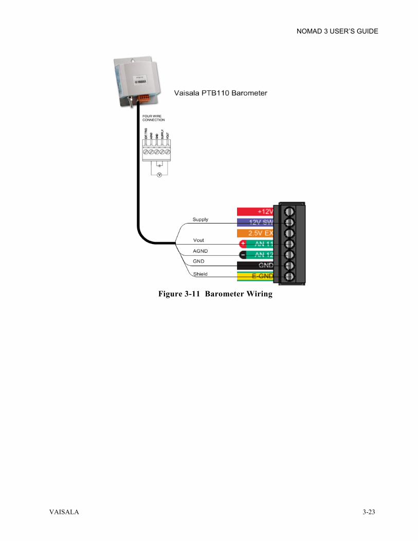
Nomad 3 supports a limited range of differential analog input measurement intended to eliminate error from using a common ground to power the sensor. Figure 2-7 shows the wiring for a Vaisala PTB110 barometer. The sensor power references the ground (GND) terminal, while the analog output ground (AGND) is wired to AN 12 (–). The Nomad 3 input connector block shows the polarity restrictions for differential mode with a red (+) for the odd inputs and a black (–) for the even inputs.

NOMAD 3 USER’S GUIDE
2-6 M211756EN-A
Figure 2-7 PTB110 Wired for Differential Mode
A differential pair must be sequential: AN 1(+), AN 2(–); AN 3(+), AN 4(–); etc… The purpose of the differential measurement is to eliminate error from sharing power ground. Analog negative (–) must be at ground potential or higher; up to 100mV above ground. This is a sufficient range for typical low current sensors and cable resistance.
2.2.3 REMOTE COMMUNICATIONS The Nomad 3 Data Logger can be equipped with an optional 2G GSM modem. The user is responsible for acquiring a SIM card and setting up a local cellular data plan with a local provider. The SIM card is inserted in the modem and allows for data transmission via Email and FTP. When activated on SkyServe, the Nomad 3 can send regular status updates to the Nomad 3 Account Manager site.
NOTE It is suggested to test the modem in house to reduce troubleshooting issues before field installation of the Nomad 3.

NOMAD 3 USER’S GUIDE
VAISALA 3-1
CHAPTER 3 INSTALLATION
3.1 INTRODUCTION This chapter contains instructions for installation of the Nomad 3 Data Logger.
3.2 STANDARD DATA LOGGER PACKING LIST The following items are included in the delivery of the Nomad 3 Data Logger. ITEM QUANTITY NOTES
Nomad 3 1 ea. USB Flash Drive 1 ea. Use to load setup files, update firmware, or export
data direct from the Nomad 3 0.025" [0.64mm] Flathead Screwdriver 1 ea. For use when wiring up sensors to connector blocks Quick Start Guide 1 ea. Activation Card 1 ea. Included inside the Nomad 3 enclosure Wet Erase Marker w/ Velcro 1 ea. Attach this to the Velcro strip inside the front cover
of the Nomad 3 Mounting Hardware Kit 1 ea. Includes two [2] pole mount brackets, four [4] 10-
32×3/8" SEMS screws, and two [2] worm drive clamps
Mounting Foot Kit 1 ea. Option for mounting to flat surface (or inside another enclosure)
USB-A to USB-B Cable 1 ea. For later use when computer to Nomad 3 communications are available
Extra 6-32×5/8" SEMS Screws 2 ea. Extra 10-32×5/8" SEMS Screws 2 ea. Extra 5-Pin Terminal Blocks 2 ea. Extra 7-Pin Terminal Blocks 2 ea.

NOMAD 3 USER’S GUIDE
3-2 M211756EN-A
3.3 TOOLS AND EQUIPMENT The following tools and equipment are required for installation of the Nomad 3 Data Logger. ITEM QUANTITY USED FOR
#2 Philips Screwdriver 1 ea. Removing PCB/cover to access modem for SIM installation and antenna connection
5/16" Nut-Driver 1 ea. Securing and tightening hose clamps to tower Metal Shears 1 ea. Cutting hose clamps to length for pole mounting Wire Strippers 1 ea. Preparing ends of sensor cable for connector termination Adjustable Wrench 1 ea. Tightening PG glands Electrical Tape 1 roll Ensure safety while wiring power connections Box Cutter 1 ea. Cutting cable gland to route terminated cables Wire ties +20 ea. Cable management Mini SIM card (optional) 1 ea. Cellular modem communications
3.4 SITE INFORMATION Site preparation requires that onsite facilities, materials, services, and equipment are completely defined and available prior to installation. When installing on a met tower, ensure that all wiring and cabling are done properly at the sensor prior to installation. Label sensor cables to facilitate wiring at the Nomad 3.
3.5 UNPACKING AND REPACKING Carefully unpack all equipment from crates and boxes while inspecting for damage. Retain original packaging or similar materials for repacking. When storing:
• Disconnect all power sources and batteries. • Remove any fuses. • Ensure that any exposed holes in the wiring glands are plugged shut with a short piece of wire or
a billet plug. • Latch the door shut and store in a warm and dry room. • Do not store outside when not in use.
3.6 SITE SAFETY Site safety procedures shall be observed when following any and all procedures in this document.

NOMAD 3 USER’S GUIDE
VAISALA 3-3
3.7 PRE-INSTALLATION PREPARATION Before installing the Nomad 3 in the field, refer to the following pre-installation checklist:
• Check that all parts have been received as listed in section 3.2 and appear to be in working condition.
• If a modem option has been selected, plan to test the modem in house before installing the Nomad 3 in the field. Obtain a SIM card with a service plan, and make sure that it has been activated. See section 3.9.1 for details to test the modem.
• Plan all sensor wiring ahead of time and determine if any necessary accessories are needed outside of the standard Nomad 3 offering. See sections 2.2.2 and 3.9.5 for more information regarding sensor wiring.
• Create an input setup file for the Nomad 3 as described in section 4.3.
3.8 SKYSERVE CREDENTIALS & ACTIVATION Creating a free SkyServe account is required for creating setup files and managing the Nomad 3 using online tools. A SkyServe account is also required in order to activate a Nomad 3. Activation allows Vaisala to provide remote troubleshooting services if required in the field.
3.8.1 CREATE AN ADMIN SKYSERVE ACCOUNT Create a free SkyServe account to being the activation process. The first person to create an account from your company will become the admin account. Determine ahead of time if you’d like an individual to be the account manager or if a group with a shared email address should become your account manager. Email [email protected] for additional assistance. STEP ACTION
1 On a device with internet access, go to www.skyserve.net/nomad3 and select the Nomad 3 Account Manager by clicking the image on the right.
2 Below the login window, click the link that
says Create an account.

NOMAD 3 USER’S GUIDE
3-4 M211756EN-A
STEP ACTION
3 Fill out all fields with admin account information and click “Create”.
4 If an admin account has already been created
for your company, an error window will appear. Contact your company admin to create a general user account.
3.8.2 CREATE A GENERAL USER SKYSERVE ACCOUNT A general user account is managed by the admin user of your company. The account admin must create a new general user account for you. You can change your password to protect your account afterwards. STEP ACTION
1 Contact your account manager and have them follow steps 1 through 6 below. 2 On a device with internet access, the admin
should go to www.skyserve.net/nomad3 and select the Nomad 3 Account Manager by clicking the image on the right.
3 The account manager sign in to their account

NOMAD 3 USER’S GUIDE
VAISALA 3-5
STEP ACTION
4 Select the Nomad 3 user management link.
5 Select the Create a SkyServe user link.
6 Fill out the Email address, First and Last Name
and temporary Password information for the general user account. If needed, create an Account expiration date. Also select any existing activated data loggers that the general user should have access to in the dropdown list of Assigned Sites. Click Save when all information has been filled out.
7 On a device with internet access, the general
user should go to www.skyserve.net/nomad3 and select the Nomad 3 Account Manager by clicking the image on the right.

NOMAD 3 USER’S GUIDE
3-6 M211756EN-A
STEP ACTION
8 Select the Forgot your password link below the sign in window.
9 Fill in your email address and press the button
to send yourself a password reset email.
10 In the password reset email, click the link to bring you to the account manager password reset
website. Follow the instructions for password requirements and click the save changes button. 11 Return to the Account Manager login page and
enter your new password to login to the Account Manager site.

NOMAD 3 USER’S GUIDE
VAISALA 3-7
3.8.3 ACTIVATE THE NOMAD 3 Activating a Nomad 3 should be performed by a SkyServe user in your company. If a user outside your company’s account registers the Nomad 3 (i.e. a consultant or installer), you will not have control over the data being sent to SkyServe from the data logger as well as certain remote operations. STEP ACTION
1 On a device with internet access, go to www.skyserve.net/nomad3 and select the Nomad 3 Account Manager by clicking the image on the right.
2 Login to the Account Manager with your
SkyServe credentials created in the previous sections.
3 Select the Activate a Nomad 3 link.
4 In the activation screen of SkyServe, enter the
activation code, box ID, and country of operation in the appropriate fields. This information is found on the Activation Card, located in the plastic sleeve, attached to the bottom-right of the Nomad 3 door.
5 Enter your SkyServe login credentials at the bottom and click “Register”. The Nomad 3 is now
activated under your company’s SkyServe account.

NOMAD 3 USER’S GUIDE
3-8 M211756EN-A
3.9 INSTALLATION PROCEDURES The following installation procedures should be performed in the order presented. Skip any optional sections that do not apply to your configured Nomad 3 Data Logger. STEP ACTION
1 If cellular service is used for communication, install the mini SIM card and antenna as instructed in section 3.9.1.
2 Mount the Data Logger enclosure to the tower as instructed in section 3.9.2. 3 Ground the Data Logger enclosure as instructed in section 3.9.3. 4 Connect the power source as instructed in section 3.9.4. 5 Connect the sensors as instructed in section 3.9.5.
3.9.1 MODEM PROVISIONING (OPTIONAL) If cellular service is used for communication:
• The Nomad 3 must be equipped with a GSM modem. • The user must acquire a standard Mini SIM card (2FF) and data plan from a local GSM provider.
The SIM card must be unlocked and have a static IP address. Refer to the modem label inside the Nomad 3 enclosure for information that may be required by the GSM provider for SIM card activation.
3.9.1.1 SIM CARD INSTALLATION Install the SIM card as instructed in this section. It is strongly suggested to test the modem before installation, though these steps may be performed before or after mounting the Data Logger enclosure on site. Refer to Figure 3-1 and Figure 3-2 for this procedure.
WARNING Follow all ESD and safety procedures while working on electronic equipment.

NOMAD 3 USER’S GUIDE
VAISALA 3-9
Figure 3-1 Data Logger Enclosure Front Panel Removal & GSM Modem
STEP ACTION
1 Rotate the twist latch on the right side of the Data Logger enclosure, then open the door. 2 With a Phillips screwdriver, loosen the six (6) screws holding the front panel to the enclosure.
Place the screws in the accessories kit box until later. 3 Move the loose end of the ground wire away from the PCB stack. 4 Grasp the front panel by the sensor connectors and lift away from the enclosure. 5 While holding the front panel, disconnect the ribbon cable from the modem carrier PC board.
Place the front panel in the accessories kit box for safe storage. 6 Insert the SIM card into the SIM card slot on the left side of the modem as shown in Figure 3-1.
Start by sliding the latch down to unlock the SIM card slot. 7 Press the SIM card into the card slot until it clicks into place. 8 Slide latch up to lock the SIM card into place.
SIM Card Slot
Latch
Modem Antenna Connector

NOMAD 3 USER’S GUIDE
3-10 M211756EN-A
3.9.1.2 STANDARD MODEM ANTENNA INSTALLATION The GSM Modem requires an antenna in order to receive a signal. It is strongly suggested to test the modem in house where a cell signal is present before installation in the field.
Figure 3-2 Standard Modem Antenna Cable Routing in Data Logger Enclosure
STEP ACTION
1 Screw the top of the antenna onto the antenna base. 2 Push antenna cable through the slice in the outer gland and the gland nut. 3 Push cable through the slice in the inner gland and gland nut, and connect with modem. If any
holes are unused, cut off a small piece of cable and insert in the hole. 4 Obtain the PCB stack and reattach the ribbon cable to the Modem PC board. 5 Place the front panel onto the enclosure aligning screw holes. 6 Attach the ground wire to the PCB stack at the lower left corner with one (1) of the 6-32 screws. 7 Secure the remaining five (5) screws through the holes in the PCB stack and tighten them down. 8 Create a modem setup file per your service provider as described in section 4.4. 9 Power up the Nomad 3 as described in section 5.2.1. 10 Load the setup file as described in section 5.4.2.1. 11 Test the modem as described in section 5.3.4.2. 12 Replace the front panel with the six (6) screws making sure the ground wire is attached at the
bottom left corner of the PCBA.

NOMAD 3 USER’S GUIDE
VAISALA 3-11
3.9.1.3 YAGI MODEM ANTENNA AND LIGHTNING PROTECTION INSTALLATION A Yagi modem antenna may be needed in remote areas where cell service is limited. The Yagi modem antenna is routed differently and is usually best tested on site after proper grounding is already in place. See Figure 3-3 for installation.
Figure 3-3 Yagi Antenna & Lightning Arrestor Cable Routing

NOMAD 3 USER’S GUIDE
3-12 M211756EN-A
STEP ACTION
1 Attach the N-male end of the Yagi antenna cable to the Yagi antenna. 2 Attach the SMA male end of the Yagi antenna cable to one side of the lightning arrestor. 3 Attach one end of the SMA jumper cable to the other end of the lightning arrestor. 4 Route the other end of the SMA jumper cable through the glands of the Data Logger enclosure
and attach to the modem like the standard antenna cable (see previous section). 5 The lightning arrestor has a grounding cable which needs to be clamped to a solid grounding wire
which is installed by the user. 6 The lightning arrestor can be mounted to the pole with the included L-bracket and a standard
hose clamp. 7 Obtain the PCB stack and reattach the ribbon cable to the Modem PC board. 8 Place the front panel onto the enclosure aligning screw holes. 9 Attach the ground wire to the PCB stack at the lower left corner with one (1) of the 6-32 screws. 10 Secure the remaining five (5) screws through the holes in the PCB stack and tighten them down. 11 Create a modem setup file per your service provider as described in section 4.4. 12 Power up the Nomad 3 as described in section 5.2.1. 13 Load the setup file as described in section 5.4.2.1. 14 Test the modem as described in section 5.3.4.2. 15 Replace the front panel with the six (6) screws making sure the ground wire is attached at the
bottom left corner of the PCBA.

NOMAD 3 USER’S GUIDE
VAISALA 3-13
3.9.2 TOWER MOUNTING The following procedure describes the method for mounting the Nomad 3 to a round tower. The bands included in the mounting kit will fit a tower diameter up to 16" [406mm]. Alternate mounting methods inside a larger enclosure or to a lattice tower should be planned using the four plastic mounting feet instead of the band clamp kit.
Figure 3-4 Data Logger Enclosure-Tower Mounting
STEP ACTION
1 Add 6" [150mm] to the diameter of your tower and cut the two (2) band clamps in the mounting kit to length using metal shears.
2 Secure the two mounting brackets to the back of the enclosure with the provided 10-32 screws. Tighten with a Phillips screwdriver.
3 Thread the band clamps through the slots in the mounting brackets. 4 Position the enclosure to the tower, and tighten the band clamps to the tower using a 5/16" nut
driver.

NOMAD 3 USER’S GUIDE
3-14 M211756EN-A
3.9.3 GROUNDING ENCLOSURE The following procedure describes the proper method for grounding the Nomad 3. Use of a 6AWG ground wire is recommended for use with the Nomad 3 for electrical protection against lightning strikes.
Figure 3-5 Ground Wire Connections
STEP ACTION
1 Route a 6AWG ground wire from the ground post along the tower to the bottom of the logger. 2 Route the ground wire into the logger through the outer hole in the bottom gland. 3 Route the ground wire to the ground lug and tighten in place with a flat head screwdriver.

NOMAD 3 USER’S GUIDE
VAISALA 3-15
3.9.4 CONNECT POWER SOURCE If a power source other than the Nomad 3 Power Enclosure is installed, the source must provide 12VDC at 1.25A with proper fusing. The Nomad 3 requires a minimum of 10.5VDC. Do not exceed 16VDC.
WARNING Follow all ESD and safety procedures while working on electronic equipment.
Figure 3-6 Nomad 3 to Power Enclosure Wiring

NOMAD 3 USER’S GUIDE
3-16 M211756EN-A
STEP ACTION
1 Mount the power enclosure to tower. Use instructions for the logger enclosure in section 3.9.2. 2 Make sure the fused trailer hitch between the battery and the charge regulator is disconnected
before routing power cables. Twist and pull to disconnect it. 3 Route included power cable through bottom cable gland of power enclosure. 4 Mount the solar panel to the solar bracket with the adjustable slide clamps. Mount the solar
bracket to the tower with the included hose clamps. Adjust the direction and angle of the solar panel for maximum charging at the site.
5 Route the solar panel wires through the gland in the bottom of the Power Enclosure. 6 Strip back the jacketing of the power cable and connect the RED wire to X2.5 (DCout/Switch)
and the BLACK wire to X2.4 (GND) on the Charge Regulator. 7 On the logger side, route the other end of the power cable through the PG21 cable gland. Strip
the wires back and connect the RED wire to 12V Power, and the BLACK wire to GND in the two pin connector on the Main PCB.
8 Strip back the jacketing of the solar panel wires and connect the RED wire to X1.5 (SOL1in+) and the BLACK wire to X1.4 (GND) on the Charge Regulator. Remove the connector for ease of routing if needed.
9 Remove the slack in all cables routed through the Power Enclosure cable gland and tighten the gland nut around the cables.
10 Check all wiring is correct and secured properly. Re-connect fused trailer hitch between the battery and the Charge Regulator. Twist and push together to connect it.

NOMAD 3 USER’S GUIDE
VAISALA 3-17
3.9.5 CONNECT SENSORS TO DATA LOGGER Mount sensors according to the manufacturer’s instructions. Mark each end of the sensor wire to identify the sensor connected to it. Follow the steps in this procedure to route the sensor wires to the Nomad 3. Follow best practices when wiring sensors such as incorporating a "drip loop" in all cabling to prevent water ingress from traveling down the cables in to any connection points. STEP ACTION
1 Plan where to connect each sensor on the front panel (see Figure 3-7). Make note of the terminal block (A-F) and the input connector (AN 1-12 or CTR 1-12) for each sensor using the template below. The sensor connection information will be used to create an Input Setup file for the Nomad 3. For installation, use the white board inside the front cover of the Nomad 3 to note the sensor connections as well.
2 Cut sensor cables to a blunt end except for the GPS cable which has protective tubing over the
pre-terminated cables. 3 Poke a hole in the multi-gland using a screwdriver for each sensor cable. 4 Push the cables through the holes in the multi-gland from the outside of the enclosure.

NOMAD 3 USER’S GUIDE
3-18 M211756EN-A
STEP ACTION
5 Remove the protective tube on the GPS cable and route the wires to the GPS input connector. See Figure 3-8 for proper wiring. Strip the end of the other sensor wires and terminate them to the appropriate input connectors. See Figure 3-8 through Figure 3-18 and the sensor manufacturer’s wiring to determine voltage, ground and data connections. - Analog sensors are connected to the top row (green labels with AN xx).
NOTE For differential analog inputs, the odd AN inputs are positive while the even AN inputs are for negative voltage.
- Counter sensors are connected to the middle row (bright blue labels with CTR xx). - Special sensors are connected to the bottom row.
NOTE Special sensors apart from the GPS are not currently available, but will be field upgradable with future firmware releases.
Each sensor block has an earth ground connection (yellow/green) for attaching the shield wire. The shield wire is suggested for use to prevent possible lightning damage to the Nomad 3 and the sensor.
6 Pull the slack out of the wires so that the outside of the gland’s membrane pops back out around the cable.

NOMAD 3 USER’S GUIDE
VAISALA 3-19
Figure 3-7 Input Types and Sensor Wiring
ANALOG
COUNTER
SPECIAL

NOMAD 3 USER’S GUIDE
3-20 M211756EN-A
Figure 3-8 Sensor Connection for Vaisala Low Power Sensors

NOMAD 3 USER’S GUIDE
VAISALA 3-21
Figure 3-9 Sensor Connection for NRG Low Power Sensors

NOMAD 3 USER’S GUIDE
3-22 M211756EN-A
3.9.5.1 ANALOG OUTPUT SENSORS USING DIFFERENTIAL INPUT MODE WIRING The following figures show the typical wiring for analog output sensor using differential input mode. This wiring is recommended for tower top sensors or cases with very long cables.
• Wiring for the Vaisala HMP155 Temperature and Humidity Probe is shown in Figure 3-10. • Wiring for the Vaisala PTB110 Barometer is shown in Figure 3-11.
Figure 3-10 Temperature and Humidity Probe Wiring
NOMAD 3 USER’S GUIDE
VAISALA 3-23
Figure 3-11 Barometer Wiring

NOMAD 3 USER’S GUIDE
3-24 M211756EN-A
3.9.5.2 SENSORS WITH REED SWITCHES WIRING A Reed Switch device requires a pull-up resistor connected between the counter input and the 12V+ supply. Use a 10KOhm 1/8th Watt resistor at a minimum.
• Wiring for a standard Reed Switch Rain Gauge is shown in Figure 3-12. • Wiring for a standard Reed Switch Anemometer is shown in Figure 3-13.
Figure 3-12 Reed Switch Rain Gauge Wiring
Figure 3-13 Reed Switch Anemometer Wiring
10 ΚΩ "pull-up"
Red (typ.) to CTRBlack (typ.) to GND

NOMAD 3 USER’S GUIDE
VAISALA 3-25
3.9.5.3 MULTIPLE SENSOR WIRING Wiring for multiple counter and analog sensors are shown in Figure 3-14 and Figure 3-15.
Figure 3-14 Multiple Counter Sensors Wiring
Figure 3-15 Multiple Analog Sensor Wiring
NOMAD 3 USER’S GUIDE
3-26 M211756EN-A
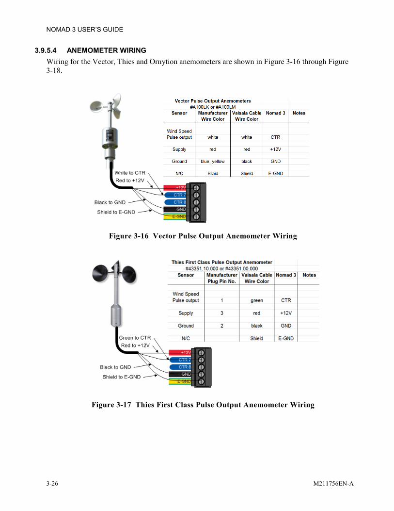
3.9.5.4 ANEMOMETER WIRING Wiring for the Vector, Thies and Ornytion anemometers are shown in Figure 3-16 through Figure 3-18.
Figure 3-16 Vector Pulse Output Anemometer Wiring
Figure 3-17 Thies First Class Pulse Output Anemometer Wiring

NOMAD 3 USER’S GUIDE
VAISALA 3-27
Figure 3-18 Ornytion AC Output Anemometer Wiring
3.10 INSPECTION Verify that all components are connected properly and that facility power is in the correct range prior to energizing the equipment.
3.11 PHYSICAL SECURITY Both the Nomad 3 enclosure and the Power Enclosure latches can be equipped with a lock to prevent unwanted entry. The holes in the latch can accept a 3/8" [9mm] diameter lock. For additional security, it is suggested to mount both enclosures inside of a larger, metal security enclosure.

NOMAD 3 USER’S GUIDE
3-28 M211756EN-A
This page was intentionally left blank.

NOMAD 3 USER’S GUIDE
VAISALA 4-1
CHAPTER 4 NOMAD 3 TOOLBOX
4.1 INTRODUCTION This chapter provides the procedures for creating setup files to configure the Nomad 3 Data Logger. It provides instruction to create setup files using the Online Nomad 3 Toolbox found at www.skyserve.net/nomad3. The Nomad 3 Toolbox is a web-based application (Online Toolbox) that contains all the tools needed for creating setup files, processing downloaded and exported data, and managing your SkyServe account. The Offline Nomad 3 Toolbox is a standalone application with the same features as the online version (except for encryption management), but can be used when internet connectivity is not available. The Offline Nomad 3 Toolbox can be found on the product page found at www.vaisala.com/nomad3. Setup files created in the Nomad 3 Toolbox on your personal computer are saved to the USB flash drive from where they can be imported to the Nomad 3 using the graphical user interface as described in section 5.4.2.1.
4.1.1 ACCESSING THE ONLINE NOMAD 3 TOOLBOX Follow this procedure to access the Online Nomad 3 Toolbox. The Toolbox is used to create and save all setup files for importation via USB drive to the Nomad 3. STEP ACTION
1 Login to www.skyserve.net/nomad3 or open the Nomad 3 Offline Toolbox installed on your computer. If this is the first use of the toolbox, set up your account when prompted.
2 On www.skyserve.net/nomad3, click on Nomad 3 Toolbox.

NOMAD 3 USER’S GUIDE
4-2 M211756EN-A
STEP ACTION
3 Enter your SkyServe username and password credentials to login.
4 You are now in the Online Nomad 3 Toolbox
environment.
4.1.2 INSTALLING THE OFFLINE NOMAD 3 TOOLBOX Follow this procedure to download the Offline Nomad 3 Toolbox. STEP ACTION
1 Download the Offline Nomad 3 Toolbox from the Vaisala website at www.vaisala.com/nomad3. 2 Navigate to your computer’s download folder and run the Nomad3Toolbox.msi executable.
Follow the onscreen instructions for installation. 3 The Nomad 3 Toolbox is now installed on your
computer. Open the program from the start menu or by double clicking the icon shortcut to open the Offline Nomad 3 Toolbox.
4 When connected to the internet, check for updates to the Offline Nomad 3 Toolbox under the Help
dropdown menu.
NOMAD 3 USER’S GUIDE
VAISALA 4-3
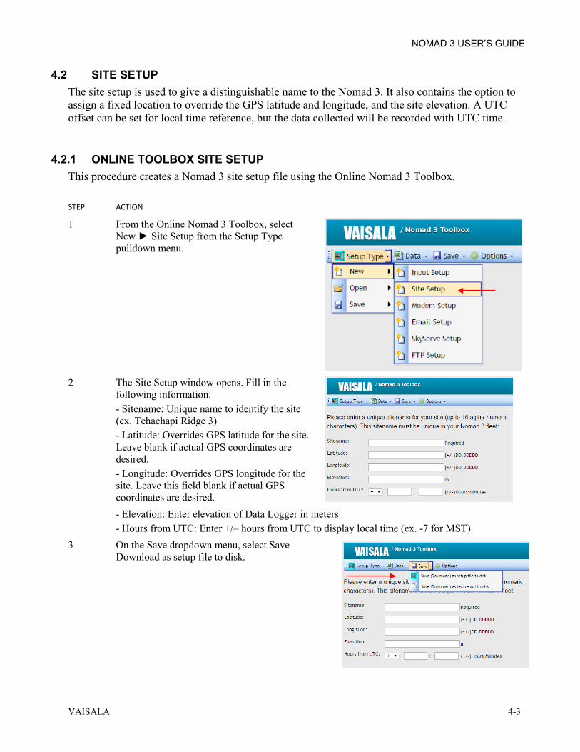
4.2 SITE SETUP The site setup is used to give a distinguishable name to the Nomad 3. It also contains the option to assign a fixed location to override the GPS latitude and longitude, and the site elevation. A UTC offset can be set for local time reference, but the data collected will be recorded with UTC time.
4.2.1 ONLINE TOOLBOX SITE SETUP This procedure creates a Nomad 3 site setup file using the Online Nomad 3 Toolbox. STEP ACTION
1 From the Online Nomad 3 Toolbox, select New Site Setup from the Setup Type pulldown menu.
2 The Site Setup window opens. Fill in the
following information. - Sitename: Unique name to identify the site (ex. Tehachapi Ridge 3) - Latitude: Overrides GPS latitude for the site. Leave blank if actual GPS coordinates are desired. - Longitude: Overrides GPS longitude for the site. Leave this field blank if actual GPS coordinates are desired. - Elevation: Enter elevation of Data Logger in meters - Hours from UTC: Enter +/– hours from UTC to display local time (ex. -7 for MST)
3 On the Save dropdown menu, select Save Download as setup file to disk.

NOMAD 3 USER’S GUIDE
4-4 M211756EN-A
STEP ACTION
4 Enter a unique filename to identify this site’s setup file. The Site Setup file will save with a .n3ss extension in the downloads folder. Move this file to a USB thumb drive for import to the Nomad 3 as described in section 5.4.2.1.
4.2.2 OFFLINE TOOLBOX SITE SETUP This procedure creates a Nomad 3 site setup file using the Offline Nomad 3 Toolbox. STEP ACTION
1 Open the Offline Nomad 3 Toolbox which will default to a new Site Setup page.
2 Fill in the following information.
- Sitename: Unique name to identify the site (ex. Tehachapi Ridge 3). - Latitude: Overrides GPS latitude for the site. Leave blank if actual GPS coordinates are desired. - Longitude: Overrides GPS longitude for the site. Leave this field blank if actual GPS coordinates are desired.Elevation: Enter elevation of Data Logger in meters. - Hours from UTC: Enter +/– hours from UTC to display local time (ex. -7 for MST).
3 On the File dropdown menu, select Save.
4 Enter a unique filename to identify this site setup file. The Site Setup file will save with a .n3ss
extension. Select a network folder location and/or put a copy of the file on a USB thumb drive for import to the Nomad 3 as described in section 5.4.2.1.

NOMAD 3 USER’S GUIDE
VAISALA 4-5
4.3 INPUT SETUP The input setup is used to configure the Nomad 3 for the particular sensors that will be wired up to it. Planning the sensor setup should be done before field installation. For coherent readings, all sensors must be configured properly.
4.3.1 ONLINE TOOLBOX INPUT SETUP This procedure creates a Nomad 3 sensor input setup file using the Online Nomad 3 Toolbox. STEP ACTION
1 From the Online Nomad 3 Toolbox, select New Input Setup from the Setup Type pulldown menu.
2 The Input Setup window will open. Begin by setting up the Counter Inputs referencing the sensor
setup plan from section 3.9.5. 3 Click the row of the counter input which will
be wired to the sensor. Under the Type menu heading, select the type of sensor from the dropdown list as shown.
4 Under the Model menu heading, select the
model of the sensor from the dropdown list as shown. The units, slope, offset and threshold values will pre-populate for a specific sensor, though some values may be adjustable. If your sensor is not listed, select the "Other" option from the dropdown list and type in the name of the sensor.

NOMAD 3 USER’S GUIDE
4-6 M211756EN-A
STEP ACTION
5 Enter all remaining information in the fields for the sensor. - User Input Description – something descriptive about the sensor to help with troubleshooting in the field. - Serial Number – optional field to also help with identification of the sensor in the field - Height – sensor height from the ground in meters - Azimuth – orientation of sensor on tower in degrees - 1 min Data – check this box if you require one minute data from this sensor. Note this will take up more space on the internal storage of the Nomad 3.
6 Double check all fields are correct for the sensor. 7 If the same type of sensor is used elsewhere,
with the filled out row highlighted in yellow, press the Action icon next to the counter input to which the other sensor will be wired in order to copy the setup information. Otherwise, repeat steps 3 through 6 to set up a different Counter Input.
8 Next setup the Analog Inputs referencing the sensor setup plan from section 3.9.5. 9 Click the row of the analog input which will be
wired to the sensor. Under the Type menu heading, select the type of sensor from the dropdown list as shown.
10 Under the Model menu heading, select the
model of the sensor from the dropdown list as shown. The units, slope, offset and threshold values will pre-populate for a specific sensor, though some values may be adjustable. If your sensor is not listed, select "Other" from the dropdown list and type in the name of the sensor.
NOMAD 3 USER’S GUIDE
VAISALA 4-7
STEP ACTION
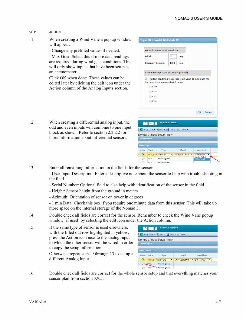
11 When creating a Wind Vane a pop up window will appear. - Change any prefilled values if needed. - Max Gust: Select this if more data readings are required during wind gust conditions. This will only show inputs that have been setup as an anemometer. Click OK when done. These values can be edited later by clicking the edit icon under the Action column of the Analog Inputs section.
12 When creating a differential analog input, the
odd and even inputs will combine to one input block as shown. Refer to section 2.2.2.2 for more information about differential sensors.
13 Enter all remaining information in the fields for the sensor.
- User Input Description: Enter a descriptive note about the sensor to help with troubleshooting in the field. - Serial Number: Optional field to also help with identification of the sensor in the field - Height: Sensor height from the ground in meters - Azimuth: Orientation of sensor on tower in degrees - 1 min Data: Check this box if you require one minute data from this sensor. This will take up more space on the internal storage of the Nomad 3.
14 Double check all fields are correct for the sensor. Remember to check the Wind Vane popup window (if used) by selecting the edit icon under the Action column.
15 If the same type of sensor is used elsewhere, with the filled out row highlighted in yellow, press the Action icon next to the analog input to which the other sensor will be wired in order to copy the setup information. Otherwise, repeat steps 9 through 13 to set up a different Analog Input.
16 Double check all fields are correct for the whole sensor setup and that everything matches your
sensor plan from section 3.9.5.

NOMAD 3 USER’S GUIDE
4-8 M211756EN-A
STEP ACTION
17 On the Save dropdown menu, select Save Download as setup file to disk.
18 Enter a unique filename to identify this input setup file. The Input Setup file will save with a
.n3is extension in the downloads folder. Copy this file to a USB thumb drive for import to the Nomad 3 as described in section 5.4.2.1.
4.3.2 OFFLINE TOOLBOX INPUT SETUP This procedure creates a Nomad 3 input setup file using the Offline Nomad 3 Toolbox. STEP ACTION
1 Open the Offline Nomad 3 Toolbox which will default to a new Site Setup page.
2 Select the Input Setup option from the Setup
Type pulldown menu.
3 The Input Setup window opens. Begin by setting up the Counter Inputs referencing the sensor
setup plan from section 3.9.5.

NOMAD 3 USER’S GUIDE
VAISALA 4-9
STEP ACTION
4 Click the row of the counter input which will be wired to the sensor. Under the Type menu heading, select the type of sensor from the dropdown list as shown.
5 Under the Model menu heading, select the
model of the sensor from the dropdown list as shown. The units, slope, offset and threshold values will pre-populate for a specific sensor, though some values may be adjustable. If your sensor is not listed, you can select the "Other" option from the dropdown list and type in the name of the sensor.
6 Enter all remaining information in the fields for the sensor.
- User Input Description: Enter a descriptive note about the sensor to help with troubleshooting in the field. - Serial Number: Optional field to also help with identification of the sensor in the field - Height: Sensor height from the ground in meters - Azimuth: Orientation of sensor on tower in degrees - 1 min Data: Check this box if you require one minute data from this sensor. Note this will take up more space on the internal storage of the Nomad 3.
7 Double check all fields are correct for the sensor. 8 If the same type of sensor is used elsewhere,
with the filled out row highlighted in yellow, press the Action icon next to the counter input to which the other sensor will be wired in order to copy the setup information. Otherwise, repeat steps 4 through 7 to set up a different Counter Input.
9 Next setup the Analog Inputs referencing the sensor setup plan from section 3.9.5.

NOMAD 3 USER’S GUIDE
4-10 M211756EN-A
STEP ACTION
10 Click the row of the analog input which will be wired to the sensor. Under the Type menu heading, select the type of sensor from the dropdown list as shown.
11 Under the Model menu heading, select the
model of the sensor from the dropdown list as shown. The units, slope, offset and threshold values will pre-populate for a specific sensor, though some values may be adjustable. If your sensor is not listed, select "Other" from the dropdown list and type in the name of the sensor.
12 When creating a Wind Vane a pop up window
will appear. - Change any prefilled values if needed. - Max Gust: Select this if more data readings are required during wind gust conditions. This will only show inputs that have been setup as an anemometer. Click OK when done. These values can be edited later by clicking the edit icon under the Action column of the Analog Inputs section.

NOMAD 3 USER’S GUIDE
VAISALA 4-11
STEP ACTION
13 When creating a differential analog input, the odd and even inputs will combine to one input block as shown. Refer to section 2.2.2.2 for more information about differential sensors.
14 Enter all remaining information in the fields for the sensor.
- User Input Description: Enter a descriptive note about the sensor to help with troubleshooting in the field. - Serial Number: Optional field to also help with identification of the sensor in the field - Height: Sensor height from the ground in meters - Azimuth: Orientation of sensor on tower in degrees - 1 min Data: Check this box if you require one minute data from this sensor. Note this will take up more space on the internal storage of the Nomad 3.
15 Double check all fields are correct for the sensor. Remember to check the Wind Vane popup window (if used) by selecting the edit icon under the Action column.
16 If the same type of sensor is used elsewhere, with the filled out row highlighted in yellow, press the Action icon next to the analog input to which the other sensor will be wired in order to copy the setup information. Otherwise, repeat steps 10 through 15 to set up a different Analog Input.
17 Double check all fields are correct for the whole sensor setup and that everything matches your
sensor plan from section 3.9.5. 18 On the File dropdown menu, select Save.
19 Enter a unique filename to identify this input setup file. The Input Setup file will save with a
.n3is extension. Select a network folder location and/or put a copy of the file on a USB thumb drive for import to the Nomad 3 as described in section 5.4.2.1.

NOMAD 3 USER’S GUIDE
4-12 M211756EN-A
4.4 MODEM SETUP If a modem is installed in the Nomad 3, it must be configured to enable remote telemetry using the Nomad 3 Toolbox. The modem must be enabled in order to use data transfer via Email and/or FTP, and for sending status updates to SkyServe.
4.4.1 ONLINE TOOLBOX MODEM SETUP This procedure creates a Nomad 3 modem setup file using the Online Nomad 3 Toolbox. STEP ACTION
1 From the Online Nomad 3 Toolbox, select the New Modem Setup option from the Setup Type pulldown menu.
2 The Modem Setup window will open. Fill in
the following information. - Click on the Enable modem checkbox to enable the modem. - Click on the Enable roaming checkbox to enable roaming if desired. Check with your service provider about your roaming plan to avoid unexpected data charges. - Modem Type: select the modem from the dropdown menu. - Service Provider: select the cellular provider of the SIM card from the dropdown menu. If your service provider is not listed, contact [email protected].
- APN: this will prepopulate for a specific service provider, but can be changed if needed. For an "Other" Service Provider, fill in the correct APN information. - PPP Username: if needed, fill in the PPP (Point-to-Point Protocol) username required by the service provider. - PPP Password: if needed, fill in the PPP password required by the service provider.

NOMAD 3 USER’S GUIDE
VAISALA 4-13
STEP ACTION
3 On the Save dropdown menu, select Save Download as setup file to disk.
4 Enter a unique filename to identify this modem setup file. The Modem Setup file will save with a
.n3ms extension in the downloads folder. Copy this file to a USB thumb drive for import to the Nomad 3 as described in section 5.4.2.1.
4.4.2 OFFLINE TOOLBOX MODEM SETUP This procedure creates a Nomad 3 modem setup file using the Offline Nomad 3 Toolbox. STEP ACTION
1 Open the Offline Nomad 3 Toolbox which will default to a new Site Setup page.

NOMAD 3 USER’S GUIDE
4-14 M211756EN-A
STEP ACTION
2 Select the Modem Setup option from the Setup Type pulldown menu.
3 The Nomad 3 Modem Setup window will
open. Fill in the following information. - Click on the Enable modem checkbox to enable the modem. - Click on the Enable roaming checkbox to enable roaming if desired. Check with your service provider about your roaming plan to avoid unexpected data charges. - Modem Type: select the modem from the dropdown menu.
- Service Provider: select the cellular provider of the SIM card from the dropdown menu. If your service provider is not listed, contact [email protected]. - APN: this will prepopulate for a specific service provider, but can be changed if needed. For an "Other" Service Provider, fill in the correct APN information. - PPP Username: if needed, fill in the PPP (Point-to-Point Protocol) username required by the service provider. - PPP Password: if needed, fill in the PPP password required by the service provider.
4 On the File dropdown menu, select Save.
5 Enter a unique filename to identify this modem setup file. The Modem Setup file will save with a
.n3ms extension. Select a network folder location and/or put a copy of the file on a USB thumb drive for import to the Nomad 3 as described in section 5.4.2.1.

NOMAD 3 USER’S GUIDE
VAISALA 4-15
4.5 EMAIL SETUP With telemetry enabled, the Nomad 3 can be configured to send data files via email. The email setup file configures the Nomad 3 to send those files daily to a user-defined list of email addresses. Emailed data requires a configured modem and data service.
4.5.1 ONLINE TOOLBOX EMAIL SETUP This procedure creates a Nomad 3 email setup file using the Online Nomad 3 Toolbox. STEP ACTION
1 From the Online Nomad 3 Toolbox, select the New Email Setup option from the Setup Type pulldown menu.
2 The Email Setup window opens. Fill in the
following information. - Select the Enable email data delivery checkbox to enable emails. - Type the full email address of each recipient in the Recipient address box.
3 On the Save dropdown menu, select Save
Download as setup file to disk.
4 Enter a unique filename to identify this email setup file. The Email Setup file will save with a
.n3gs extension in the downloads folder. Copy this file to a USB thumb drive for import to the Nomad 3 as described in section 5.4.2.1.

NOMAD 3 USER’S GUIDE
4-16 M211756EN-A
4.5.2 OFFLINE TOOLBOX EMAIL SETUP This procedure creates a Nomad 3 email setup file using the Offline Nomad 3 Toolbox. STEP ACTION
1 Open the Offline Nomad 3 Toolbox which will default to a new Site Setup page.
2 Select the Email Setup option from the Setup
Type pulldown menu.
3 The Nomad 3 Email Setup window will open.
Fill in the following information. - Select the Enable email data delivery checkbox to enable emails. - Type the full email address of each recipient in the Recipient address box.
4 On the File dropdown menu, select Save.

NOMAD 3 USER’S GUIDE
VAISALA 4-17
STEP ACTION
5 Enter a unique filename to identify this email setup file. The Email Setup file will save with a .n3gs extension. Select a network folder location and/or put a copy of the file on a USB thumb drive for import to the Nomad 3 as described in section 5.4.2.1.
4.6 FTP SETUP With telemetry enabled, the Nomad 3 can be configured to send data files to an FTP server. Data sent to an FTP site requires a configured modem and data service.
4.6.1 ONLINE TOOLBOX FTP SETUP This procedure creates a Nomad 3 FTP setup file using the Online Nomad 3 Toolbox. STEP ACTION
1 From the Online Nomad 3 Toolbox, select New FTP Setup option from the Setup Type pulldown menu.
2 The FTP Setup window will open. Fill in the
following information. - Select the Enable FTP Data Delivery checkbox to enable FTP. - FTP server name: Enter the FTP server name in the box. - Username: Enter the username to access the FTP server in the box. - Password: Enter the password used to access the FTP server in the box. - FTP directory: Enter the FTP directory path in the box (optional).

NOMAD 3 USER’S GUIDE
4-18 M211756EN-A
STEP ACTION
3 On the Save dropdown menu, select Save Download as setup file to disk.
4 Enter a unique filename to identify this FTP setup file. The FTP Setup file will save with a .n3fs
extension in the downloads folder. Copy this file to a USB thumb drive for import to the Nomad 3 as described in section 5.4.2.1.
4.6.2 OFFLINE TOOLBOX FTP SETUP This procedure creates a Nomad 3 FTP setup file using the Offline Nomad 3 Toolbox. STEP ACTION
1 Open the Offline Nomad 3 Toolbox which will default to a new Site Setup page.
2 Select the FTP Setup option from the Setup
Type pulldown menu.

NOMAD 3 USER’S GUIDE
VAISALA 4-19
STEP ACTION
3 The FTP Setup window will open. Fill in the following information - Select the Enable FTP Data Delivery checkbox to enable FTP. - FTP server name: Enter the FTP server name in the box. - Username: Enter the username to access the FTP server in the box. - Password: Enter the password used to access the FTP server in the box. - FTP directory: Enter the FTP directory path in the box (optional).
4 On the File dropdown menu, select Save.
5 Enter a unique filename to identify this FTP setup file. The FTP Setup file will save with a .n3fs
extension. Select a network folder location and/or put a copy of the file on a USB thumb drive for import to the Nomad 3 as described in section 5.4.2.1.

NOMAD 3 USER’S GUIDE
4-20 M211756EN-A
4.7 SKYSERVE SETUP With telemetry enabled, the Nomad 3 can send status updates to the Nomad 3 Account Manager site. A SkyServe user can view the status of any Nomad 3 that they have been assigned access to by their account manager.
4.7.1 ONLINE TOOLBOX SKYSERVE SETUP This procedure creates a Nomad 3 SkyServe setup file using the Online Nomad 3 Toolbox. STEP ACTION
1 From the Online Nomad 3 Toolbox, select New SkyServe Setup option from the Setup Type pulldown menu.
2 The SkyServe Setup window will open. Fill in
the following information. - Select the Enable Nomad 3 connect to SkyServe checkbox to enable status bits to be sent to SkyServe.
3 On the Save dropdown menu, select Save
Download as setup file to disk.
4 Enter a unique filename to identify this SkyServe setup file. The SkyServe Setup file will save
with a .n3ys extension in the downloads folder. Copy this file to a USB thumb drive for import to the Nomad 3 as described in section 5.4.2.1.

NOMAD 3 USER’S GUIDE
VAISALA 4-21
4.7.2 OFFLINE TOOLBOX SKYSERVE SETUP This procedure creates a Nomad 3 SkyServe setup file using the Offline Nomad 3 Toolbox. STEP ACTION
1 Open the Offline Nomad 3 Toolbox which will default to a new Site Setup page.
2 Select the SkyServe Setup option from the
Setup Type pulldown menu.
3 The SkyServe Setup window opens. Fill in the
following information. - Select the Enable Nomad 3 to send status information to SkyServe checkbox to enable status bits to be sent to SkyServe.
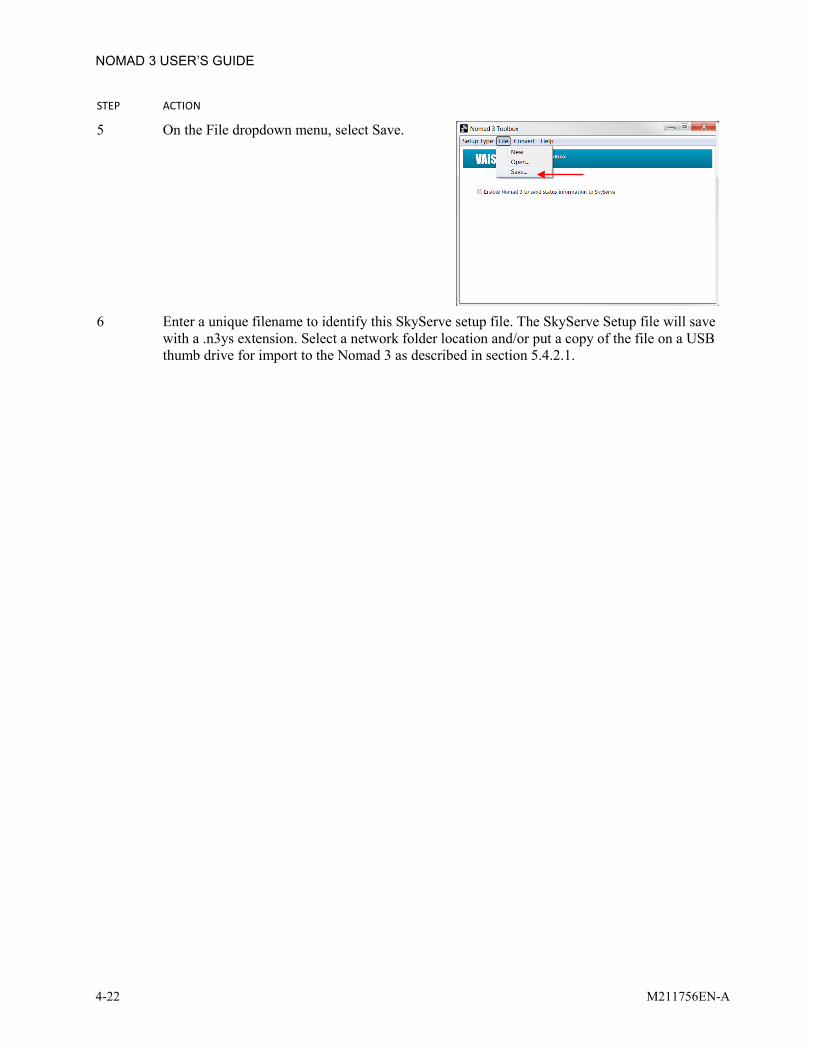
NOMAD 3 USER’S GUIDE
4-22 M211756EN-A
STEP ACTION
5 On the File dropdown menu, select Save.
6 Enter a unique filename to identify this SkyServe setup file. The SkyServe Setup file will save
with a .n3ys extension. Select a network folder location and/or put a copy of the file on a USB thumb drive for import to the Nomad 3 as described in section 5.4.2.1.

NOMAD 3 USER’S GUIDE
VAISALA 4-23
4.8 ENCRYPTION SETUP Encryption can be enabled on the Nomad 3 as an additional security measure to protect site data. An encryption setup file must be generated through the Online Nomad 3 Toolbox to ensure that SkyServe can catalog and manage your encryption files with added security. Use the same encryption file for all loggers managed under the same company admin account, though different encryption files can be generated for different loggers. If using multiple encryption files, keep track of which encryption files are loaded onto specific data loggers for ease of data decryption later.
Figure 4-1 Encryption Management Workflow

NOMAD 3 USER’S GUIDE
4-24 M211756EN-A
4.8.1 ONLINE TOOLBOX ENCRYPTION SETUP This procedure creates a Nomad 3 Encryption setup file using the Online Nomad 3 Toolbox. STEP ACTION
1 From the Online Nomad 3 Toolbox, select Manage Data Encryption Setup option from the Data pulldown menu.
2 Click on the Create encryption file link.
3 Fill in an encryption setup file name as an
identifier.
4 Press the Create encryption file button to generate the file. The Encryption Setup file will save
with a .n3es extension in the downloads folder. Move this file to a USB thumb drive for import to the Nomad 3 as described in section 5.4.2.1.
5 Once generated, the encryption file also saves to the Toolbox under your SkyServe credentials. The encryption setup file can be downloaded at any time by selecting the Download encryption file link. Select the encryption setup file or the Encryption disable setup file from the dropdown list to obtain another copy of the setup file.

NOMAD 3 USER’S GUIDE
VAISALA 4-25
4.9 EDIT SETUP FILES If setup files need to be edited, you can open an existing file in the Nomad 3 Toolbox to change certain values. Encryption files cannot be reopened for editing.
4.9.1 ONLINE TOOLBOX EDITING SETUP FILES This procedure describes how to open Nomad 3 setup files using the Online Nomad 3 Toolbox. STEP ACTION
1 From the Online Nomad 3 Toolbox, select Open XXXX Setup option from the Setup Type pulldown menu.
2 Navigate to the folder location where the setup file is located and choose the file to edit. Click the
Open button. 3 The setup file opens on the screen. Make changes to and save the file as described in the create
setup file procedures found in sections 4.2 through 4.7.
4.9.2 OFFLINE TOOLBOX EDITING SETUP FILES This procedure describes how to open Nomad 3 setup files using the Offline Nomad 3 Toolbox. STEP ACTION
1 Open the Offline Nomad 3 Toolbox which will default to a new Site Setup page.

NOMAD 3 USER’S GUIDE
4-26 M211756EN-A
STEP ACTION
2 Select the XXXX Setup option from the Setup Type pulldown menu which you’re looking to edit. The XXXX Setup window will open.
3 Select Open from the File pulldown menu.
4 Navigate to the folder location where the setup file is located and choose the file to edit. Click the
Open button. 5 The setup file opens on the screen. Make changes to and save the file as described in the create
setup file procedures found in sections 4.2 through 4.7.

NOMAD 3 USER’S GUIDE
VAISALA 5-1
CHAPTER 5 ON SITE OPERATIONS
5.1 INTRODUCTION This chapter provides instructions for operating the Nomad 3 Data Logger as installed on site.
5.2 POWER ON/OFF PROCEDURES The Data Logger does not have a power on/off switch. Power is applied through the power cable to the front panel.
5.2.1 POWER ON PROCEDURE Follow this procedure to power on the Nomad 3. STEP ACTION
1 Connect power to the Data Logger at the front panel power connector. Verify power source is on.
2 Wait for Data Logger to bootup. This may take a few minutes. 3 When Main window displays, the Data Logger is ready to use.
5.2.2 POWER OFF PROCEDURE Avoid powering off the logger during a firmware update, file download or file upload via USB. STEP ACTION
1 Disconnect the power connector from the Data Logger front panel or turn off power source.

NOMAD 3 USER’S GUIDE
5-2 M211756EN-A
5.3 DATA LOGGER MENUS The Nomad 3 Main Window, shown in Figure 5-1, may show indicators after loading certain setup files to the Nomad 3 via the USB flash drive.
Figure 5-1 Main Window Indicators

NOMAD 3 USER’S GUIDE
VAISALA 5-3
Figure 5-2 shows the Menu Windows as they would appear when you first turn on the Nomad 3. Menus display only two (2) options at a time due to the display size, though may have more than two (2) options in its list. Menus displaying a down arrow to the right of the second option have further options in the list. - Use the up/down arrow buttons to navigate up and down a list with the dot indicator. - Use the right/left arrow buttons to navigate between different menus. The look of some menus may change after loading setup files as described in section 5.4.2.1 or enabling security features as described in section 5.4.1.4.
Figure 5-2 Data Logger Menus
circular menu structure using left/right arrow
buttons
« DATA MENU »View Inputs View SetupSELECT BACK
« STATUS MENU »No System Alerts SiteSELECT BACK
« MODEM MENU »Modem not detected Modem disabled BACK
« SYSTEM MENU »System Restart Firmware VersionSELECT BACK
Vaisala Nomad32015-01-01 15:24:07(N3-00090)MENU SLEEP
« SECURITY MENU »Change PIN Encryption: OffSELECT BACK
« SKYSERVE MENU »SkyServe disabled
BACK
« EMAIL MENU »Email disabled
BACK
« FTP MENU »FTP disabled
BACK

NOMAD 3 USER’S GUIDE
5-4 M211756EN-A
Table 5-1 Data Logger Menus Description MENU DESCRIPTION
Main Displays site information, date and time. Upon startup, the site name is the Data Logger Box ID. After loading a site setup file, this will change to whatever has been selected as the site name. - MENU provides access to the following sub menus. - SLEEP causes the display to go blank (sleep) and puts the Data Logger into a low power mode after 10 minutes. Awaken by pressing any button. It may take 2-3 seconds to awake if the Data Logger is in low power mode. Press the rectangular keypad under each option to access that option
STATUS Provides access to status information of the Data Logger. This includes system alerts, site information, battery and internal temperature status, time and GPS status. See section 5.3.1 for more info about the Status Menu.
DATA Provides access to view the inputs as well as the input setup information. See section 5.3.2 for more info about the Data Menu.
SECURITY Provides access to change the PIN and displays the encryption status. When the PIN is enabled, this changes the display on the Main window. When an encryption setup file has been loaded, the menu options change. See section 5.3.3 for more info about the Security Menu.
MODEM Provides view access to the modem setup. Displays whether a modem is detected and whether the modem is disabled. When a modem setup file has been loaded, the menu options change. See section 5.3.4 for more info about the Modem Menu.
SKYSERVE Provides view access to the SkyServe setup. Displays whether SkyServe is disabled. When a SkyServe setup file is loaded, the menu options change. See section 5.3.5 for more info about the SkyServe Menu.
EMAIL Provides view access to the Email setup. Displays whether email is disabled. When an email setup file is loaded, the menu options change. See section 5.3.6 for more info about the Email Menu.
FTP Provides view access to the FTP setup. Displays whether FTP is disabled. When an FTP setup file is loaded, the menu options change. See section 5.3.7 for more info about the FTP Menu.
SYSTEM Provides access to system restarts and info about the firmware version. See section 5.3.8 for more info about the System Menu.

NOMAD 3 USER’S GUIDE
VAISALA 5-5
5.3.1 STATUS MENU The Status Menu provides access to status information of the Data Logger’s site, alerts, battery, internal temperature, time and GPS. - Press the up and down keypad arrows to select the option (bullet to the left of the selected option) then press the rectangular softkey under the word SELECT. - Click the rectangular softkey under the word BACK at any time to return to the previous menu.
Figure 5-3 STATUS Menu Options
- Alert 1 of 1 -!Ground wiring error Check GND/=/EGND BACK
No System Alerts
OK
« STATUS MENU »No System Alerts Site ↓SELECT BACK
SITE NAME & UNIT ID "Tehachapi Ridge3" 00090 BACK
BATTERY & SUPPLIESBattery: 13.45 V 12V Bus: 13.39 VSw12V Bus: 13.34 V2.5V Bus: 2.496 VInt Temp: 27.3°C BACK
CURRENT TIME (LOCAL)2015-01-01 15:24:07UTC Offset: +4 h LOC/UTC BACK
CURRENT TIME (UTC)2015-01-01 11:24:09UTC Offset: +4 h LOC/UTC BACK
GPS STATUSNo Response 21h ago RetrySELECT
GPS STATUSValid Fix 13m ago RetrySELECT
- Alert 1 of 1 -Ground wiring OK Alert has cleared BACK
« STATUS MENU »! 1 System Alert Site Battery Time GPSSELECT BACK

NOMAD 3 USER’S GUIDE
5-6 M211756EN-A
Table 5-2 STATUS Menu Options Description OPTION DESCRIPTION
SYSTEM ALERTS
a. No system alerts are displayed when there are no system alerts. b. If system alerts are displayed, the next window will show you which alerts are current. Multiple alerts can be viewed by pressing the left/right arrows. After troubleshooting and fixing the alert (see 0), the screen will indicate that the error has been cleared.
SITE NAME & UNIT ID
Displays site information from the site configuration file. Long names scroll across the screen.
BATTERY & SUPPLIES
Displays battery and power supply voltages, as well as internal temperature.
CURRENT TIME
Displays the current date and time and the UTC offset. Press the center rectangular keypad to toggle the display between local and UTC time.
GPS Displays the last GPS connection status and allows retry of GPS connection test if last attempt yielded no response. GPS allows for time synchronization if no telemetry is enabled. The GPS will attempt a connection every 6hrs.
5.3.2 DATA MENU The Data Menu contains information pertaining to the input sensors.
Figure 5-4 DATA Menu Options
Table 5-3 DATA Menu Options Description OPTION DESCRIPTION
View Inputs Select View Inputs to look at the instantaneous output values of the sensors which are wired to the Data Logger. Further info of this feature in section 5.3.2.1.
View Setup Select View Setup to review the sensor setup of the Data Logger. Further info of this feature in section 5.3.2.2.
« DATA MENU »View Inputs View SetupSELECT BACK

NOMAD 3 USER’S GUIDE
VAISALA 5-7
5.3.2.1 VIEW INPUTS The View Inputs selection shows the instantaneous readings of the counter and analog sensors wired to the input blocks A through F. The data displayed in these windows are informational only. - Use the up/down arrow buttons to scroll through the sensor information on a single terminal block. - Use the left/right arrow buttons to move between blocks. Note the position of the sensor selected before moving to another block will track to the same position on the next block. The menus in this view are circular. - Press the center softkey button to toggle the units from raw voltage/frequency units to sensor units (m/s, °C, hPa, etc…) - Press the right softkey button to select BACK and return to the previous screen.
Figure 5-5 Input Blocks
Table 5-4 Input Blocks Description OPTION DESCRIPTION
INPUT BLOCK-A Displays information for Analog and Counter devices 1 & 2 INPUT BLOCK-B Displays information for Analog and Counter devices 3 & 4 INPUT BLOCK-C Displays information for Analog and Counter devices 5 & 6 INPUT BLOCK-D Displays information for Analog and Counter devices 7 & 8 INPUT BLOCK-E Displays information for Analog and Counter devices 9 & 10 INPUT BLOCK-F Displays information for Analog and Counter devices 11 & 12
« INPUTS BLOCK-A »AN1: 1.230 V AN2: 0.987 V CTR1: 1.3 Hz CTR2: 0.4 Hz UNITS BACK
« INPUTS BLOCK-B »AN3: 3.769 V AN4: 2.100 V CTR3: 0.0 Hz CTR4: 0.8 Hz UNITS BACK
« INPUTS BLOCK-F »AN11: 0.000 V AN12: 0.000 V CTR11: 0.0 Hz CTR12: 0.0 Hz UNITS BACK

NOMAD 3 USER’S GUIDE
5-8 M211756EN-A
5.3.2.2 VIEW SETUP OF INPUTS The Counter and Analog Inputs display the input setup information and data received from the devices installed on the Nomad 3.
Figure 5-6 VIEW SETUP Menu Options
Table 5-5 VIEW SETUP Menu Options Description OPTION DESCRIPTION
Counter Inputs View information on each counter device 1 through 12. Different types of sensors may have different information displayed in its setup.
Analog Inputs View information on each analog device 1 through 12. Different types of sensors may have different information displayed in its setup.
VIEW SETUPCounter Inputs Analog InputsSELECT BACK
« INPUT: CTR 1 »Type: Anemometer Model: SWI/Vaisala S/N: 1297 1m Average: no Threshold: 0V Slope: 0.766 Offset: 0.324 Units: m/s Height: 60.00 Azimuth: 30.0° Desc: Anem A @ 60m Vane@max: AN 0 BACK
« INPUT: CTR 1 »Type: Wind Vane Model: SW/Vaisala S/N: 876 1m Average: no Deadband: 5.0° Differential: no Range: 0-2.5V Sw12V Power: no Slope: 144.000 Offset: 0.000 Units: deg Height: 60.00 Azimuth: 30.0° Desc: Vane A @ 60m BACK

NOMAD 3 USER’S GUIDE
VAISALA 5-9
5.3.3 SECURITY MENU The Security menu displays information about data and device security. Use this menu to enable a PIN to access certain menus through the Nomad 3 GUI. Data encryption status can also be reviewed from this menu.
Figure 5-7 SECURITY Menu Options
Table 5-6 SECURITY Menu Options Description
OPTION DESCRIPTION
Change PIN Create or disable your Data Logger PIN. This PIN is used to protect data export or file loading windows on the Data Logger. The Change PIN procedure is described in section 5.4.1.4.
Encryption Indicates if data is encrypted.
5.3.4 MODEM MENU The Modem menu displays information about whether a modem is present or enabled. Sub-menus allow for modem testing and show previous call logs if enabled.
Figure 5-8 MODEM Menu Options (disabled and enabled)
Table 5-7 MODEM Menu Options Description
OPTION DESCRIPTION
View Setup See section 5.3.4.1 Set Time Test See section 5.3.4.2 Call Log See section 5.3.4.3
CHANGE LOGIN PINNew PIN: _
DISABLE CANCEL
DAYFILE ENCRYPTIONData not encrypted
OK
« SECURITY MENU »Change PIN Encryption: OffSELECT BACK
« MODEM MENU »Modem not detected Modem disabled BACK
« MODEM MENU »View Setup Set Time Test Call LogSELECT BACK

NOMAD 3 USER’S GUIDE
5-10 M211756EN-A
5.3.4.1 MODEM VIEW SETUP This option displays the information from the Modem Setup file. Figure 5-9 displays a portion of a typical modem setup file. The modem setup file is created by the Nomad 3 Toolbox and is then loaded into the Nomad 3.
Figure 5-9 MODEM Setup
Table 5-8 MODEM Setup Menu List Descriptions Option DESCRIPTION
Modem Displays the type of modem. Provider Displays the service provider enabled by the user. Roaming Displays whether or not roaming has been enabled by the user. apn This is a default modem setting for the modem’s network access point name (APN).
The information needed to correctly setup the modem will depend on the specific cellular network used and its requirements to access the internet. More information on creating a modem setup file can be found in section 4.4.
NOTE
For many cellular networks, only very basic information is needed to activate and use the network. For example, many networks do not require a Username or Password. Depending upon local network configuration and signal strength, it may be essential to Enable Roaming to achieve good performance. Also note that the added charges may be applied for roaming service.
MODEM SETUPModem: Novatel-GPR Provider: ATT-USA Roaming: Disabled apn=isp.cingular BACK

NOMAD 3 USER’S GUIDE
VAISALA 5-11
5.3.4.2 MODEM SET TIME TEST The Modem Set Time Test fully tests the modem’s capability to connect to the internet through the cell network. The test sequence automatically starts when selected. The test performs several steps as shown in Figure 5-10. - Hourglass symbol indicates that that step is in progress - Checkmark indicates that that step has completed successfully - × indicates failure
Figure 5-10 MODEM Time Set
Table 5-9 MODEM Set Time Test Sequence Descriptions Option DESCRIPTION
Modem Power On Tests if the ribbon cable is connected to the Modem Carrier PC board. Initializing Begins startup of modem Registering Checks connection to internet. Data Connection Checks communicate (i.e. active SIM card) Setting Sets time on data logger
If the Modem Set Time Test fails at any of these steps, refer to section 6.3.1 for troubleshooting.
5.3.4.3 MODEM CALL LOG The call log displays the modem transmits and receives results. Figure 5-11 displays a single entry for a call. Press the down/up arrow buttons to view previous connection attempt results. The long text results scroll across the display when the dot indicator is on that line.
Figure 5-11 MODEM Call Log
MODEM TIME SETModem power on Initializing BACK
MODEM CALL LOG2015-01-01 15:14 0.2min Tx=0.6KB… Signal 68% Call succeeded BACK

NOMAD 3 USER’S GUIDE
5-12 M211756EN-A
5.3.5 SKYSERVE MENU The SkyServe menu displays information about whether status chunks are being sent to SkyServe. Status data will show up in the Nomad 3 Account Manager where users are able to review the operational status of one or more Nomad 3s. See section 5.5 which details the fleet status view in the Nomad 3 Account Manager.
Figure 5-12 SKYSERVE Menu Options (disabled and enabled)
Table 5-10 SKYSERVE Menu Options Description Option DESCRIPTION
View Setup See section 5.3.5.1 Server Ping Test See section 5.3.5.2 Call Log See section 5.3.5.3
5.3.5.1 SKYSERVE VIEW SETUP This option displays the information from the SkyServe Setup file. With SkyServe enabled, the logger will send status information to SkyServe which can be viewed in the Nomad 3 Account Manager website. If SkyServe is Disabled, the setup will display only that message.
Figure 5-13 SKYSERVE Setup
« SKYSERVE MENU »View Setup Server Ping Test Call LogSELECT BACK
« SKYSERVE MENU »SkyServe disabled
BACK
SKYSERVE SETUPConnect: Daily Offset: 5.0 Min Call Time: 30 Sec Ext Calls: 5.0 Min Server: tsp-nomad3… Server Port: 49700 BACK

NOMAD 3 USER’S GUIDE
VAISALA 5-13
5.3.5.2 SKYSERVE PING TEST The SkyServe Ping Test checks the data communication path between Nomad 3 and SkyServe. The test sequence automatically starts when selected. The test performs several steps as shown in Figure 5-14. - Hourglass symbol indicates that that step is in progress - Checkmark indicates that that step has completed successfully - × indicates failure
Figure 5-14 SKYSERVE Ping Test
Table 5-11 SKYSERVE Ping Test Sequence Descriptions Option DESCRIPTION
Modem power on Tests if the ribbon cable is connected to the Modem Carrier PC board. Initializing Begins startup of modem. Signal Checking for sufficient signal strength. Registering Checks connection to internet. Data Connection Checks communicate (i.e. active SIM card). Pinging Attempts to establish communications with SkyServe.
If the SkyServe Ping Test fails at any of these steps, refer to section 6.3.4 for troubleshooting.
SKYSERVE PIN TEST Modem power on Initializing BACK

NOMAD 3 USER’S GUIDE
5-14 M211756EN-A
5.3.5.3 SKYSERVE CALL LOG The call log displays SkyServe transmits, receives or failed calls. Figure 5-15 shows a single entry for a call. Press the down/up arrow buttons to view previous connection attempt results. The long text results scroll across the display when the dot indicator is on that line.
Figure 5-15 SKYSERVE Call Log
5.3.6 EMAIL MENU The Email menu displays information about whether data files are setup for email. With email enabled, data will be sent daily.
Figure 5-16 EMAIL Menu Options (disabled and enabled)
Table 5-12 EMAIL Menu Options Description Option DESCRIPTION
View Setup See section 5.3.6.1 Send Test Email See section 5.3.6.2 Call Log See section 5.3.6.3
SKYSERVE CALL LOG2015-01-01 19:28 0.4min Tx=10.4KB… Signal 39% Call succeeded Test successful BACK
« EMAIL MENU »View Setup Send Test Email Call LogSELECT BACK
« EMAIL MENU »Email disabled
BACK

NOMAD 3 USER’S GUIDE
VAISALA 5-15
5.3.6.1 EMAIL VIEW SETUP This option displays the information from the Email Setup file.
Figure 5-17 EMAIL Setup
Table 5-13 EMAIL Send Test Sequence Descriptions Option DESCRIPTION
List Recipients This is the list of email addresses that receive emails. Send Displays the frequency which emails are sent. Offset This is a default setting which controls time offset of emails. Max Queue This is a default setting for number of day files in queue. Server This is the default IP address of the Vaisala email relay. Server Port This is the default designation for the port used. Timeout This is a default timeout setting. From Line This designates the Email from line the logger will use.
EMAIL [email protected]… [email protected]… [email protected]… BACK
EMAIL SETUPList Recipients Send: Daily Offset: 5.0 Min Max Call: 5.0 Min Max Queue: 10 Server: xxx.xx.xxx… Server Port: 2525 Timeout: 1.0 Min From Line: Nomad3D…SELECT BACK
non-selectable

NOMAD 3 USER’S GUIDE
5-16 M211756EN-A
5.3.6.2 EMAIL SEND TEST The Email Send Test will send a test email from the Nomad 3 to the recipient list. The test sequence automatically starts when selected. The test performs several steps as shown in Figure 5-18. - Hourglass symbol indicates that that step is in progress - Checkmark indicates that that step has completed successfully - × indicates failure
Figure 5-18 EMAIL Send Test
Table 5-14 EMAIL Send Test Sequence Descriptions Option DESCRIPTION
Modem power on Tests if the ribbon cable is connected to the Modem Carrier PC board. Initializing Begins startup of modem. Signal Checking for sufficient signal strength. Registering Checks connection to internet. Data Connection Checks communicate (i.e. active SIM card). Sending Attempts to send a test email to the recipient list.
If the Email Send Test fails at any of these steps, refer to section 6.3.2 for troubleshooting.
5.3.6.3 EMAIL CALL LOG The call log displays the Email transmits, receives or failed sends. Figure 5-19 shows a single entry for a call. Press the down/up arrow buttons to view previous connection attempt results. The long text results scrolls across the display when the dot indicator is on that line.
Figure 5-19 EMAIL Call Log
EMAIL SEND TEST Modem power on Initializing BACK
EMAIL CALL LOG2015-01-01 21:14 0.1min Tx=0.6KB… Signal 39% Call succeeded Test successful BACK
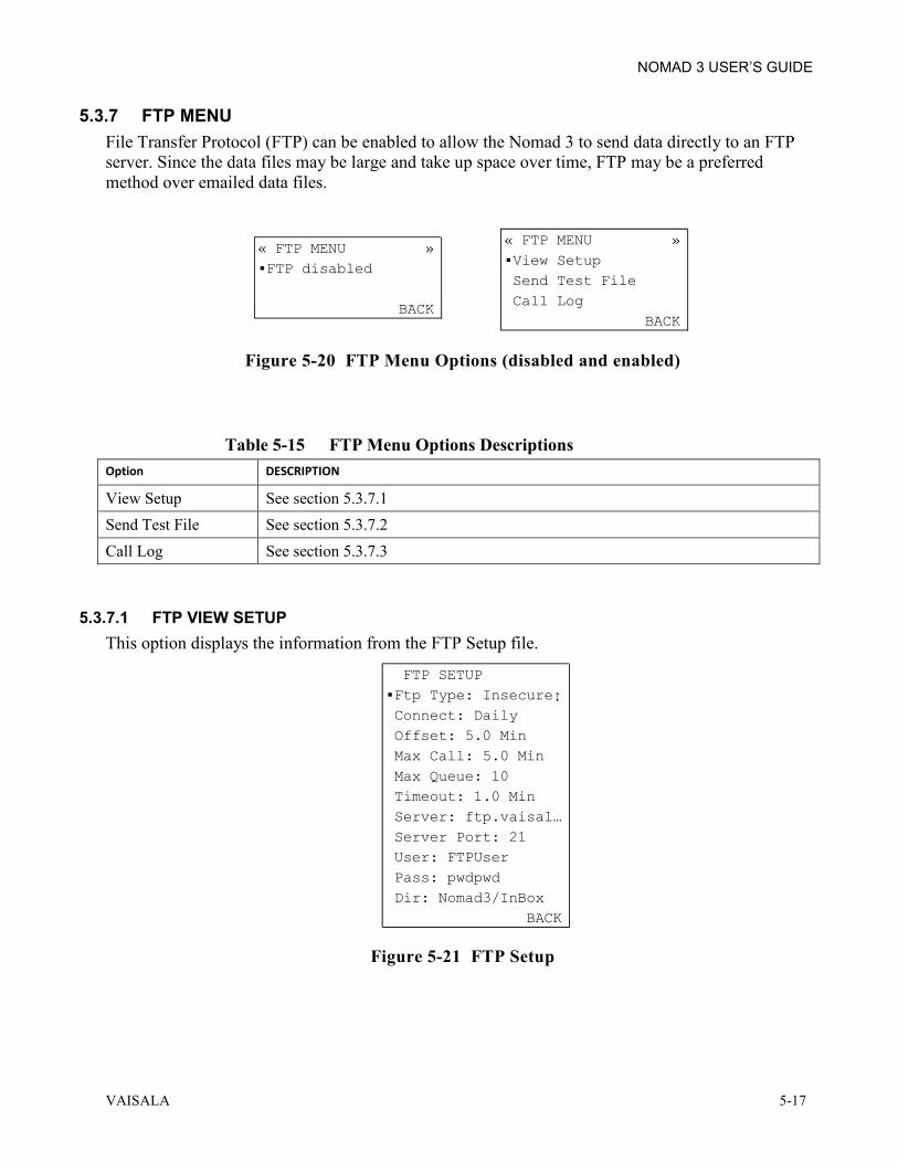
NOMAD 3 USER’S GUIDE
VAISALA 5-17
5.3.7 FTP MENU File Transfer Protocol (FTP) can be enabled to allow the Nomad 3 to send data directly to an FTP server. Since the data files may be large and take up space over time, FTP may be a preferred method over emailed data files.
Figure 5-20 FTP Menu Options (disabled and enabled)
Table 5-15 FTP Menu Options Descriptions Option DESCRIPTION
View Setup See section 5.3.7.1 Send Test File See section 5.3.7.2 Call Log See section 5.3.7.3
5.3.7.1 FTP VIEW SETUP This option displays the information from the FTP Setup file.
Figure 5-21 FTP Setup
« FTP MENU »FTP disabled
BACK
« FTP MENU »View Setup Send Test File Call Log BACK
FTP SETUPFtp Type: Insecure Connect: Daily Offset: 5.0 Min Max Call: 5.0 Min Max Queue: 10 Timeout: 1.0 Min Server: ftp.vaisal… Server Port: 21 User: FTPUser Pass: pwdpwd Dir: Nomad3/InBox BACK

NOMAD 3 USER’S GUIDE
5-18 M211756EN-A
Table 5-16 FTP Setup Options Descriptions Option DESCRIPTION
Ftp Type Either secure or insecure. Connect Displays the connection frequency. Offset Default value for time offset of connection. Max Call Default value for maximum call tine length. Max Queue Default value for maximum call tine length. Timeout Default value for timeout disconnect. Server Displays the server IP address. Server Port Displays the Server Port number. User Displays the Username. Password Displays the Password. Dir Displays the directory that FTP files will be written to.
5.3.7.2 FTP SEND TEST The FTP Send Test will send a test file from the Nomad 3 to the FTP server. The test sequence automatically starts when selected. The test performs several steps as shown in Figure 5-22. - Hourglass symbol indicates that that step is in progress - Checkmark indicates that that step has completed successfully - × indicates failure
Figure 5-22 FTP Send Test
Table 5-17 FTP Send Test Sequence Descriptions
Option DESCRIPTION
Modem power on Tests if the ribbon cable is connected to the Modem Carrier PC board. Initializing Begins startup of modem. Signal Checking for sufficient signal strength. Registering Checks connection to internet. Data Connection Checks communicate (i.e. active SIM card). Sending Attempts to send a test file to the FTP site.
If the FTP Send Test fails at any of these steps, refer to section 6.3.3 for troubleshooting.
FTP SEND TEST Modem power on Initializing BACK

NOMAD 3 USER’S GUIDE
VAISALA 5-19
5.3.7.3 FTP CALL LOG The call log displays the FTP transmits, receives and failed sends. Figure 5-23 shows a single entry for a call. Press the down/up arrow buttons to view previous connection attempt results. The long text results scroll across the display when the dot indicator is on that line.
Figure 5-23 FTP Call Log
FTP CALL LOG2015-01-01 25:42 0.1min Tx=0.6KB… Signal 58% Call succeeded Test successful BACK

NOMAD 3 USER’S GUIDE
5-20 M211756EN-A
5.3.8 SYSTEM MENUS The system menus are used to review more detailed information about the Nomad 3. Most importantly, the firmware version can be viewed from this menu to determine if an update is needed.
Figure 5-24 SYSTEM Menu Options
Table 5-18 SYSTEM Menu Options Description Option DESCRIPTION
Restart Menu PIN protected menu if enabled. Restarting the applications is a soft restart and will reload the applications running the data logging. Rebooting the system will turn the entire system off and back on again.
Firmware Version Displays the current firmware and platform versions. Open Source Software Note to see open source license information at the indicated site. Clear System ID Num PIN protected menu if enabled. The window displays the system ID and
requests an override key confirmation before clearing system ID. NOTE: Only used during a field replacement of the PCB stack. The Nomad 3 will stop recording data if the system ID is cleared.
« SYSTEM MENU »System Restart Firmware Version Open Source Info Clear System ID NumSELECT BACK
RESTART MENURestart Apps Reboot SystemSELECT BACK
FIRMWARE VERSIONN3BL-1.0Platform: 0.6 BACK
Open Source SoftwareFor more info go to:http://vaisala.com/ BACK
SYSTEM ID: N3-00090Resetting System ID Stops the System! CONTINUE BACK

NOMAD 3 USER’S GUIDE
VAISALA 5-21
5.4 OPERATIONAL PROCEDURES This section provides instructions for common operational procedures.
5.4.1 LOG IN/OUT PROCEDURES The Nomad 3 is shipped in the default mode with no PIN protection enabled. The PIN is used to protect the Nomad 3 from unwarranted tampering of setup files, firmware changes, and direct data downloads. View access is always allowed outside of the PIN login for users who are not making direct changes to files on the Nomad 3.
NOTE The user is logged out after 1 hour of inactivity with the PIN enabled. If your PIN is lost, the Nomad 3 must be activated on SkyServe in order to retrieve a recovery key.
With no PIN enabled, the Main window displays MENU above the left softkey and SLEEP above the right softkey. When logged out with the PIN enabled, the Main window displays MENU above the left softkey, LOGIN above the middle softkey, and SLEEP above the right softkey. When logged in with the PIN enabled, the Main window displays MENU above the left softkey and LOGOUT above the right softkey.
Figure 5-25 PIN Enabled/Disabled Main Menu Views
Vaisala Nomad32015-01-01 15:24:07Tehachapi Ridge3MENU SLEEP
Vaisala Nomad32015-01-01 15:24:07Tehachapi Ridge3MENU LOGOUT
Vaisala Nomad32015-01-01 15:24:07Tehachapi Ridge3MENU LOGIN SLEEP

NOMAD 3 USER’S GUIDE
5-22 M211756EN-A
5.4.1.1 ENABLE PIN PROCEDURE This procedure changes the Login PIN to a new value. PINs are 4 numeric digits. STEP ACTION
1 From the Main window, press the left softkey to go to MENU.
2 Press the right arrow button until the
SECURITY MENU displays.
3 With the dot cursor next to Change PIN, press the left softkey to SELECT. 4 Enter a 4-digit pin of your choice. Press the up
arrow button to increment and the down arrow button to decrement the number. Press the right arrow button to move to the next digit.
5 Press the left softkey button to SAVE.
6 The window will display the PIN has been
saved. Press the left softkey button to select OK.
5.4.1.2 LOGOUT PROCEDURE If the user forgets to logout, the Nomad 3 automatically logs off after 1 hour of inactive keypad presses. STEP ACTION
1 On the Main window, press the right button to select LOGOUT.
2 Display goes dark and the Nomad 3 sleeps until awakened by a button press.
Vaisala Nomad32015-01-01 15:24:07Tehachapi Ridge3MENU SLEEP
« SECURITY MENU »Change PIN Encryption: OffSELECT BACK
CHANGE LOGIN PINNew PIN: _
DISABLE BACK
CHANGE LOGIN PINNew PIN: 1234
SAVE DISABLE CANCEL
New PIN Saved
OK
Vaisala Nomad32015-01-01 15:24:07Tehachapi Ridge3MENU LOGOUT

NOMAD 3 USER’S GUIDE
VAISALA 5-23
5.4.1.3 LOGIN PROCEDURE If the user does not LOGIN at the Main window, the LOGIN window displays for operations that require a log in. Operations which change the setup files or allow the user to upload files and/or download files require the PIN to be entered if enabled.
NOTE If the user forgets to logout, the Nomad 3 automatically logs off after 1 hour of inactive keypad presses.
STEP ACTION
1 On the Main window, press the middle button to select LOGIN.
2 Enter the 4-digit PIN on the LOGIN window.
Press the up arrow to increment or down arrow to decrement the number. Press the right arrow to move to the next digit.
3 After all the digits have been entered, DONE
will appear above the left softkey button. Press the left softkey button to select DONE.
4 When LOGIN SUCCESSFUL displays, press
the left softkey button to select OK.
5.4.1.4 CHANGE LOGIN PIN PROCEDURES This procedure changes the Login PIN to a new value. PINs are 4 numeric digits. There are two (2) methods to change the Login PIN: 1. Main window as described in section 5.4.1.4.1. 2. Security Menu as described in section 5.4.1.4.2.
Vaisala Nomad32015-01-01 15:24:07Tehachapi Ridge3MENU LOGIN SLEEP
LOGIN Enter PIN: _
BACK
LOGIN Enter PIN: 1234
DONE BACK
LOGIN SUCCESSFUL
CHANGEOK PIN

NOMAD 3 USER’S GUIDE
5-24 M211756EN-A
5.4.1.4.1 CHANGE LOGIN PIN FROM MAIN WINDOW Follow this procedure to change the Login PIN from the Main window on the Nomad 3. STEP ACTION
1 On the Main window, press the middle button to select LOGIN.
2 Enter the 4-digit PIN on the LOGIN window.
Press the up arrow to increment or down arrow to decrement the number. Press the right arrow to move to the next digit.
3 After all the digits have been entered, DONE
will appear above the left softkey button. Press the left softkey button to select DONE.
4 When LOGIN SUCCESSFUL displays, press
the right softkey button to select CHANGE PIN.
5 On CHANGE LOGIN PIN window, enter the
new 4-digit PIN. Press the up arrow to increment or down arrow to decrement the number. Press the right arrow to move to the next digit.
6 After entering the 4-digit PIN, press the left button to select SAVE.
7 The window displays the PIN has been saved.
Press the left softkey button to select OK.
Vaisala Nomad32015-01-01 15:24:07Tehachapi Ridge3MENU LOGIN SLEEP
LOGIN Enter PIN: _
BACK
LOGIN Enter PIN: 1234
DONE BACK
LOGIN SUCCESSFUL
CHANGEOK PIN
CHANGE LOGIN PINNew PIN: _
DISABLE CANCEL
CHANGE LOGIN PINNew PIN: 4321
SAVE DISABLE CANCEL
New PIN Saved
OK

NOMAD 3 USER’S GUIDE
VAISALA 5-25
5.4.1.4.2 CHANGE LOGIN PIN FROM THE SECURITY MENU Follow this procedure to change the Login PIN from the Security Menu on the Nomad 3. STEP ACTION
1 On the Main window, press the left button to select MENU.
2 Press the right arrow button until the
SECURITY MENU displays.
3 With the dot cursor next to Change PIN, press the left softkey to SELECT. 4 Enter the 4-digit PIN on the LOGIN window.
Press the up arrow to increment or down arrow to decrement the number. Press the right arrow to move to the next digit.
5 After all the digits have been entered, DONE
will appear above the left softkey button. Press the left softkey button to select DONE.
6 On CHANGE LOGIN PIN window, enter the
new 4-digit PIN. Press the up arrow to increment or down arrow to decrement the number. Press the right arrow to move to the next digit.
7 After entering the 4-digit PIN, press the left button to select SAVE.
8 The window displays the PIN has been saved.
Press the left softkey button to select OK.
Vaisala Nomad32015-01-01 15:24:07Tehachapi Ridge3MENU LOGIN SLEEP
« SECURITY MENU »Change PIN Encryption: OffSELECT BACK
LOGIN Enter PIN: _
BACK
LOGIN Enter PIN: 1234
DONE BACK
CHANGE LOGIN PINNew PIN: _
DISABLE CANCEL
CHANGE LOGIN PINNew PIN: 4321
SAVE DISABLE CANCEL
New PIN Saved
OK

NOMAD 3 USER’S GUIDE
5-26 M211756EN-A
5.4.1.5 DISABLE LOGIN PIN PROCEDURE This procedure disables the PIN on the Nomad 3 and removes protection from unwarranted tampering of setup files, firmware changes, and direct data downloads. There are two (2) methods to disable the Login PIN: 1. Main window as described in section 5.4.1.5.1. 2. Security Menu as described in section 5.4.1.5.2.
5.4.1.5.1 DISABLE LOGIN PIN FROM MAIN WINDOW Follow this procedure to disable the Login PIN from the Main window on the Nomad 3. STEP ACTION
1 On the Main window, press the middle button to select LOGIN.
2 Enter the 4-digit PIN on the LOGIN window.
Press the up arrow to increment or down arrow to decrement the number. Press the right arrow to move to the next digit.
3 After all the digits have been entered, DONE
will appear above the left softkey button. Press the left softkey button to select DONE.
4 When LOGIN SUCCESSFUL displays, press
the right softkey button to select CHANGE PIN.
5 On CHANGE LOGIN PIN window, press the
center softkey button to select DISABLE.
6 On CHANGE LOGIN PIN window, press the
left softkey button to SAVE. If deleting the Login PIN is not intended, select CANCEL or ENABLE so that a new PIN may be entered.
7 When PIN Disabled displays, press the left
button to select OK.
8 The PIN is now disabled and the Main window will no longer show the LOGIN or LOGOUT
features.
Vaisala Nomad32015-01-01 15:24:07Tehachapi Ridge3MENU LOGIN SLEEP
LOGIN Enter PIN: _
BACK
LOGIN Enter PIN: 1234
DONE BACK
LOGIN SUCCESSFUL
CHANGEOK PIN
CHANGE LOGIN PINNew PIN: _
DISABLE CANCEL
CHANGE LOGIN PINNew PIN: NONE
SAVE ENABLE CANCEL
New PIN Saved
OK
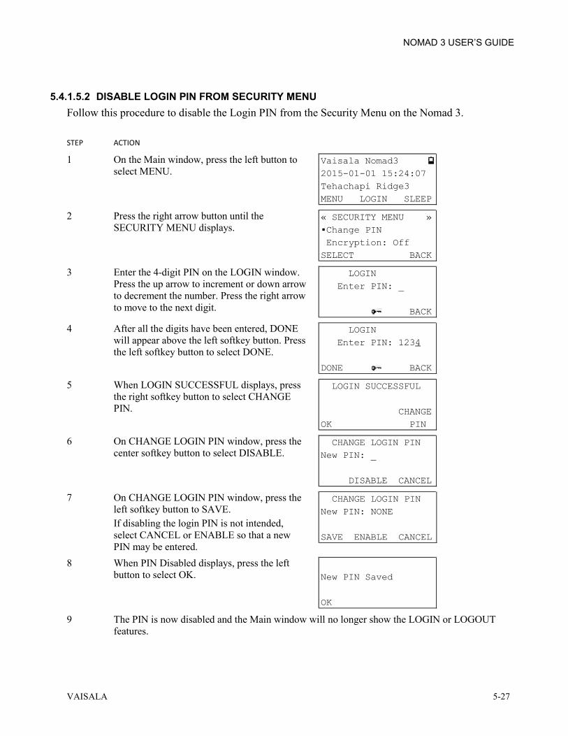
NOMAD 3 USER’S GUIDE
VAISALA 5-27
5.4.1.5.2 DISABLE LOGIN PIN FROM SECURITY MENU Follow this procedure to disable the Login PIN from the Security Menu on the Nomad 3. STEP ACTION
1 On the Main window, press the left button to select MENU.
2 Press the right arrow button until the
SECURITY MENU displays.
3 Enter the 4-digit PIN on the LOGIN window.
Press the up arrow to increment or down arrow to decrement the number. Press the right arrow to move to the next digit.
4 After all the digits have been entered, DONE
will appear above the left softkey button. Press the left softkey button to select DONE.
5 When LOGIN SUCCESSFUL displays, press
the right softkey button to select CHANGE PIN.
6 On CHANGE LOGIN PIN window, press the
center softkey button to select DISABLE.
7 On CHANGE LOGIN PIN window, press the
left softkey button to SAVE. If disabling the login PIN is not intended, select CANCEL or ENABLE so that a new PIN may be entered.
8 When PIN Disabled displays, press the left button to select OK.
9 The PIN is now disabled and the Main window will no longer show the LOGIN or LOGOUT
features.
Vaisala Nomad32015-01-01 15:24:07Tehachapi Ridge3MENU LOGIN SLEEP
« SECURITY MENU »Change PIN Encryption: OffSELECT BACK
LOGIN Enter PIN: _
BACK
LOGIN Enter PIN: 1234
DONE BACK
LOGIN SUCCESSFUL
CHANGEOK PIN
CHANGE LOGIN PINNew PIN: _
DISABLE CANCEL
CHANGE LOGIN PINNew PIN: NONE
SAVE ENABLE CANCEL
New PIN Saved
OK

NOMAD 3 USER’S GUIDE
5-28 M211756EN-A
5.4.1.6 LOGIN PIN RECOVERY PROCEDURE This procedure describes how to gain access to PIN protected Data Logger menus when the PIN is forgotten or lost. The Data Logger must have been activated on SkyServe prior to this. Instructions for activation can be found in section 3.8.3. STEP ACTION
1 Begin by locating your Data Logger Box ID. From the Main window, press the left softkey to select MENU.
2 Under the STATUS MENU, press the down
arrow followed by the left softkey to select SITE. The number displayed below the site name is the Data Logger ID. Write this down.
3 On a device connected to the web, your company’s account manager must go to
www.skyserve.net/nomad3/reset and login. 4 The account manager must enter the Data
Logger ID and press the Generate PIN(s) button. A 6-digit Override Key is generated. Write this down.
5 On the Data Logger, press the right softkey
until returned to the Main window. Press the middle softkey to select LOGIN. The LOGIN window can also be displayed by trying to access any secure menu.
6 On the LOGIN window, press the middle softkey to select the (key symbol).
7 Enter the key on the OVERRIDE KEY
window. Press the up arrow button to increment or down arrow button to decrement the number. Press the right arrow button to move to the next digit.
8 After entering the 6-digit Override Key, DONE displays in the bottom left corner of the window. Press the left softkey to select DONE
9 The OVERRIDE SUCCESSFUL window displays the PIN. Press the left softkey to select OK and keep the displayed PIN or press the right softkey to CHANGE PIN. The CHANGE PIN procedure is in section 5.4.1.4.
Vaisala Nomad32015-01-01 15:24:07Tehachapi Ridge3MENU LOGIN SLEEP
SITE NAME & UNIT ID "Tehachapi Ridge3" 00090 BACK
Vaisala Nomad32015-01-01 15:24:07Tehachapi Ridge3MENU LOGIN SLEEP
LOGIN Enter PIN: _
BACK
OVERRIDE KEYOverride Key: _
BACK
OVERRIDE SUCCESSFUL PIN is 1234 CHANGEOK PIN

NOMAD 3 USER’S GUIDE
VAISALA 5-29
5.4.2 LOADING SETUP FILES This section describes how to load setup files onto the Nomad 3 which were generated from the Nomad 3 Toolbox. Setup files should be created using the Online or Offline Nomad 3 Toolbox as described in 0.
5.4.2.1 IMPORT SITE SETUP FILES TO DATA LOGGER WITH USB DRIVE This procedure imports setup files to the Nomad 3 which were created or edited using the Nomad 3 Toolbox. This procedure requires a USB flash drive. STEP ACTION
1 Insert the USB drive containing the setup files into the USB port on the front panel of the Data Logger.
2 Press the button to the left of the USB port. The port LED illuminates. 3 Wait for the USB drive to be detected.
4 When the USB OPERATIONS menu displays,
press the left softkey to SELECT Import Setup.
5 If not logged in, enter the PIN as described in section 5.4.1.3. 6 The file import wizard will open up and display the Site Setup first. There are three options to
select in all setup import windows. -No Change: Keep the current setup file or default file. -Choose File: Select a file from the USB drive to import. -Factory Default: Restore the factory default file.
7 If importing a Site Setup file from the USB drive, press the down arrow button to navigate to Choose File. Press the left softkey button to SELECT. Otherwise, navigate to No Change or Factory Default and jump to step 10.
8 Press the down arrow to select the Input file to import, then press the left softkey button to SELECT.
9 The window will return to the Site Setup page
and display the file you selected.
DETECTING USB Please wait...
CANCEL
USB OPERATIONSImport Setup Export DataSELECT EJECT
SITE SETUP No Change Choose FileSELECT BACK
SELECT FILESiteSetupA SiteSetupBSELECT BACK
SITE SETUPSiteSetupA Choose FileNEXT BACK

NOMAD 3 USER’S GUIDE
5-30 M211756EN-A
STEP ACTION
10 Press the left softkey button to select NEXT or repeat steps 6-9 if a different setup file is required.
11 The next window displays the Input Setup. Follow the same procedure in steps 6-10 to import a file, skip import, or restore to factory default.
12 The next window displays the Encryption
Setup. Follow the same procedure in steps 6-10 to import a file, skip import, or restore to factory default.
13 The next window displays the Modem Setup.
Follow the same procedure in steps 6-10 to import a file, skip import, or restore to factory default.
14 The next window displays the SkyServe Setup.
Follow the same procedure in steps 6-10 to import a file, skip import, or restore to factory default.
15 The next window displays the Email Setup.
Follow the same procedure in steps 6-10 to import a file, skip import, or restore to factory default.
16 The next window displays the FTP Setup.
Follow the same procedure in steps 6-9 to import a file, skip import, or restore to factory default.
17 Press the left softkey to select FINISH or repeat steps 6-9 if a different setup file is required. 18 Press the left softkey button to select
CONFIRM.
19 Wait for import to complete. Press the left
softkey button to select OK when the successful import window appears.
20 Press right softkey button to select EJECT on
USB Operations menu.
21 When the LED turns off, remove the USB drive.
INPUT SETUPNo Change Choose FileNEXT BACK
ENCRYPTION SETUPNo Change Choose FileNEXT BACK
MODEM SETUPNo Change Choose FileNEXT BACK
SKYSERVE SETUPNo Change Choose FileNEXT BACK
EMAIL SETUPNo Change Choose FileNEXT BACK
FTP SETUPNo Change Choose FileFINISH BACK
Update setup now?
CONFIRM CANCEL
Import Successful
OK
USB OPERATIONSImport Setup Export DataSELECT EJECT

NOMAD 3 USER’S GUIDE
VAISALA 5-31
5.4.3 EXPORT SETUP FILES This procedure describes how to export setup files from the Nomad 3 via a USB flash drive. This allows you to verify what setup files are loaded on the Nomad 3 and edit them if needed by following the steps in section 4.9. This procedure requires a USB flash drive. STEP ACTION
1 Insert the USB flash drive into the DATA port on the front panel of the Nomad 3. 2 Press the button to the left of the USB port. The port LED illuminates. 3 Wait for the USB drive to be detected.
4 When USB OPERATIONS menu displays,
select Export Setup Files. Press the left softkey to SELECT.
5 If PIN enabled, enter PIN if not already logged in as described in section 5.4.1.3. 6 The setup files export to the USB drive. The setup files save themselves under a directory folder
named Nomad3Setup N3-xxxxxx_AsOf_yyyy-mm-dd_hh-mm (logger ID and date formatted).
7 Press the left softkey to select OK when the files are done exporting.
8 Press right softkey button to select EJECT on
USB Operations menu.
9 When the LED turns off, remove the USB drive.
DETECTING USB Please wait…
CANCEL
USB OPERATIONS Import Setup Export Data Update FirmwareExport Setup Files Export Log FilesSELECT EJECT
Setup Files Exported
OK
USB OPERATIONS Update Firmware Export Setup FilesSELECT EJECT

NOMAD 3 USER’S GUIDE
5-32 M211756EN-A
5.4.4 EXPORT DATA FILES This procedure describes how to download data file(s) from the Data Logger to save and analyze on a computer. This procedure requires a USB flash drive. STEP ACTION
1 Insert the USB flash drive into the USB port on the front panel of the Data Logger. 2 Press the USB power button to the left of the USB port. The LED illuminates. 3 Wait for the USB flash drive to be detected.
Troubleshoot if not connected properly
4 When USB OPERATIONS menu displays,
press down arrow to select Export Data. Press left softkey to SELECT.
5 Enter PIN if not already logged in as described in section 5.4.1.3. 6 Press down arrow to choose Export All, Export
Latest or Export Data Sample. Press left softkey to SELECT. Export Latest will load any data that was not exported from the last export. Export Data Sample will give you a single 10 minute sample of data to confirm setup files were loaded properly.
7 Wait while data is exported to the USB drive. Bars indicate progress.
8 When EXPORT FINISHED displays, press left
softkey to select OK.
9 Press right softkey to select BACK to return to the USB Operations Menu. 10 Press right softkey to select EJECT on the USB Operations Menu and turn off power to the USB
flash drive. 11 When the LED turns off, remove the USB flash drive. 12 To save data files, copy files from USB flash drive to computer. 13 To convert data for analysis, continue with section 5.4.5.
DETECTING USB Please wait…
CANCEL
USB OPERATIONS Import Setup Export Data Update Firmware Export Setup Files Export Log FilesSELECT EJECT
EXPORT DATAExport All Export Latest Export Data SampleSELECT BACK
EXPORTING DATA---------------------------------------- CANCEL
Export Finished
OK

NOMAD 3 USER’S GUIDE
VAISALA 5-33
5.4.5 DATA FILE CONVERSION PROCEDURES Nomad 3 data files can be converted into readable CSV files for data analysis. The conversion can be performed using both the Online and Offline Toolboxes though there are restrictions to file outputs using the offline toolbox. The user must have the Nomad 3 data files stored on a computer or a local network drive to use the Toolbox conversion tool. Download data directly from the data logger as described in section 5.4.4 or retrieve them from your email or FTP folder.
5.4.5.1 CONVERT DATA USING ONLINE TOOLBOX Follow this procedure to convert data files using the Online Nomad 3 Toolbox. STEP ACTION
1 Place the data files in a directory folder on your computer or network folder location. 2 Open your Browser and go to www.skyserve.net/nomad3. 3 Select the Nomad 3 Toolbox resource by
clicking the Nomad 3 Toolbox image.
4 On the Data dropdown menu, select Convert
Dayfile to CSV file.
5 Click on Select dayfile(s) then choose the
file(s) to convert from the file browser window. Select up to a month’s worth of data to convert at a time.
6 Click convert to CSV.

NOMAD 3 USER’S GUIDE
5-34 M211756EN-A
STEP ACTION
7 Select a CSV Data Template from the options shown to start processing the data files. "Data Only" exports 1 minute data and 10 minute averages into a CSV file.
"Input Setup At Top" exports 1 minute data and 10 minute averages with the input setup noted at the top of the CSV file. "Input Setup at Bottom” exports 1 minute data and 10 minute averages with the input setup noted at the bottom of the CSV file. "Windographer" exports 10 minute averages into a CSV file.
8 One or more CSV files generate and save to the download folder. After the conversions are complete, the CSV files can be imported to a spreadsheet application. - Multiple day files from the same Nomad 3 will be placed into one CSV file. - Multiple day files from different data loggers will save to separate CSV files.
5.4.5.2 CONVERT ENCRYPTED DATA USING ONLINE TOOLBOX Converting encrypted data files requires the matching decryption file loaded into the user’s Nomad 3 Toolbox environment. The Nomad 3 Toolbox will then be able to decrypt and convert data files from all data loggers that have the same encryption file.
NOTE
If the logger data was encrypted using a setup file generated from user A’s Toolbox credentials, that same user (user A) will be able to convert the data files generated from instructions in section 0 without using the following procedure. This procedure should be followed to allow user B to decrypt and convert the data files.
STEP ACTION
1 From the Online Nomad 3 Toolbox, the user who created the encryption file imported on the Nomad 3 selects Manage Data Encryption Setup option from the Data pulldown menu.

NOMAD 3 USER’S GUIDE
VAISALA 5-35
STEP ACTION
2 Select the Export decryption file link.
3 From the dropdown menu, select the
decryption file that matches the encryption file of the data.
4 Click the Export decryption file button. The decryption file will save with a .n3ds extension in
the downloads folder. Move this file to a USB thumb drive to give to another SkyServe user. 5 Insert the USB drive into the other SkyServe user’s computer. 6 From the Online Nomad 3 Toolbox, the other
SkyServe user selects Manage Data Encryption Setup option from the Data pulldown menu.
7 Select the Import decryption file link.
8 Click the Select file button and open the
decryption file on the USB drive.
9 Click the Import decryption file button. You now have the permissions to convert the encrypted
data files that match the decryption file. 10 Follow the steps in section 0 to convert the encrypted data files.

NOMAD 3 USER’S GUIDE
5-36 M211756EN-A
5.4.5.3 CONVERT DATA USING OFFLINE TOOLBOX Follow this procedure to convert data files using the Offline Nomad 3 Toolbox.
NOTE Encrypted files cannot be converted using the Offline Nomad 3 Toolbox.
STEP ACTION
1 Place the data files in a directory folder on your computer or network folder location. 2 Launch the offline Nomad 3 Toolbox. 3 From the Convert dropdown menu, select
“Select directory of dayfiles to convert to csv…”
4 Select the directory where the dayfile(s) have
been stored. Press the OK button.
5 One or more CSV files will be created and
saved in the same folder directory as the dayfiles. After the conversions are complete, the CSV files can be imported to a spreadsheet application.
- Multiple day files from the same Nomad 3 will be placed into one CSV file. - Multiple day files from different data loggers will save to separate CSV files.

NOMAD 3 USER’S GUIDE
VAISALA 5-37
5.4.6 FIRMWARE UPDATE PROCEDURE This procedure describes how to import new firmware files via a USB flash drive. This procedure requires a USB flash drive. STEP ACTION
1 Insert the USB flash drive containing the firmware file into the DATA port on the front panel of the Nomad 3.
2 Press the button to the left of the USB port. The port LED illuminates. 3 Wait for the USB drive to be detected.
4 When USB OPERATIONS menu displays,
select Update Firmware. Press left softkey to SELECT.
5 If PIN enabled, enter PIN if not already logged in as described in section 5.4.1.3. 6 Press down arrow to select new firmware file
on USB drive for import, then press left softkey to SELECT.
7 The window asks you to confirm the Firmware
update which will restart the Nomad 3. Press left softkey to CONFIRM or right softkey to CANCEL.
8 Wait for update to complete. Progress messages display during the update and the screen will go
blank. Another set of messages display until update is complete. Installation may take a few minutes. The Main window displays after successful installation has completed.
9 Remove the USB flash drive. 10 Check imported firmware version. Start by pressing the left softkey to select MENU. 11 Press left arrow button to get to the SYSTEM MENU. 12 Press down arrow to select Firmware Version then press left softkey to SELECT. 13 Confirm imported firmware version is
displayed.
DETECTING USB Please wait…
CANCEL
USB OPERATIONS Import Setup Export DataUpdate Firmware Export Setup Files Export Log FilesSELECT EJECT
UPDATE FIRMWARE N3BL-1.0 N3BL-1.1SELECT BACK
Update Firmware Now?System will restart!
CONFIRM CANCEL
FIRMWARE VERSIONN3BL-1.1Platform: 0.6 BACK

NOMAD 3 USER’S GUIDE
5-38 M211756EN-A
5.4.7 EXPORT LOG FILES This procedure describes how to export log files from the Nomad 3 via a USB flash drive. If you are having technical issues with your Nomad 3, Vaisala support staff may request log files from your Nomad 3 to analyze what may be happening. This procedure requires a USB flash drive. STEP ACTION
1 Insert the USB flash drive into the DATA port on the front panel of the Nomad 3. 2 Press the button to the left of the USB port. The port LED illuminates. 3 Wait for the USB drive to be detected.
4 When USB OPERATIONS menu displays,
select Export Log Files. Press the left softkey to SELECT.
5 If PIN enabled, enter PIN if not already logged in as described in section 5.4.1.3. 6 The setup files export to the USB drive. The setup files save themselves under a directory folder
named Nomad3LogFiles N3-xxxxxx_AsOf_yyyy-mm-dd_hh-mm (logger ID and date formatted).
7 Press the left softkey to select OK when the files are done exporting.
8 Press right softkey button to select EJECT on
USB Operations menu.
9 When the LED turns off, remove the USB drive.
DETECTING USB Please wait…
CANCEL
USB OPERATIONS Import Setup Export Data Update Firmware Export Setup FilesExport Log FilesSELECT EJECT
Log Files Exported
OK
USB OPERATIONS Export Setup FilesExport Log FilesSELECT EJECT

NOMAD 3 USER’S GUIDE
VAISALA 5-39
5.5 MONITOR SITES WITH FLEET STATUS VIEW The Data Loggers can be monitored using the Nomad 3 Account Manager on SkyServe. Use the fleet status view to review the operational state of the data loggers you have been granted access to. The Nomad 3 must have been activated (see section 3.8.3) and access granted by your company’s admin SkyServe user (see section 3.8.1) for it to show up on your fleet status page.
5.5.1 ASSIGN SITES Follow this procedure to assign a Nomad 3 to a SkyServe user. The admin SkyServe account for your company must have already been created (see section 3.8.1) and the Nomad 3 must have already been activated on SkyServe (see section 3.8.3). STEP ACTION
1 On a device with internet access, the admin should go to www.skyserve.net/nomad3 and select the Nomad 3 Account Manager by clicking the image on the right.
2 Login to the online Account Manager using the credentials setup in section 3.8. 3 Select the Nomad 3 user management link.
4 Select the Edit a SkyServe user link.
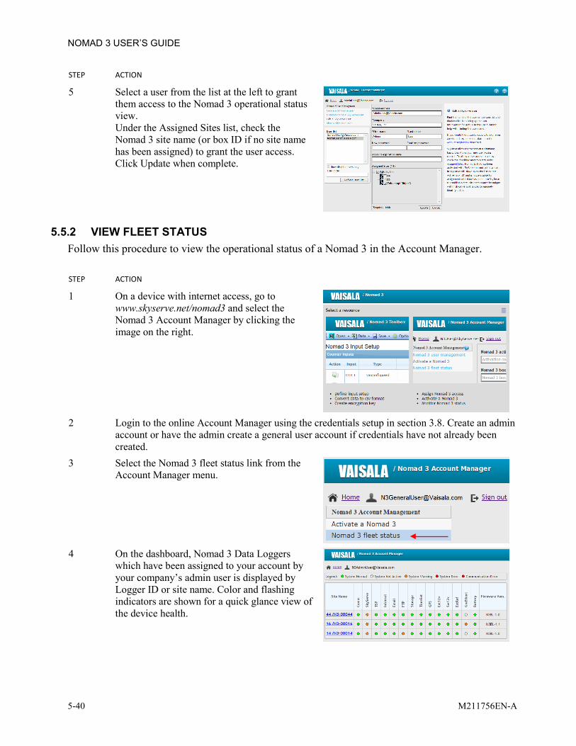
NOMAD 3 USER’S GUIDE
5-40 M211756EN-A
STEP ACTION
5 Select a user from the list at the left to grant them access to the Nomad 3 operational status view. Under the Assigned Sites list, check the Nomad 3 site name (or box ID if no site name has been assigned) to grant the user access. Click Update when complete.
5.5.2 VIEW FLEET STATUS Follow this procedure to view the operational status of a Nomad 3 in the Account Manager. STEP ACTION
1 On a device with internet access, go to www.skyserve.net/nomad3 and select the Nomad 3 Account Manager by clicking the image on the right.
2 Login to the online Account Manager using the credentials setup in section 3.8. Create an admin
account or have the admin create a general user account if credentials have not already been created.
3 Select the Nomad 3 fleet status link from the Account Manager menu.
4 On the dashboard, Nomad 3 Data Loggers
which have been assigned to your account by your company’s admin user is displayed by Logger ID or site name. Color and flashing indicators are shown for a quick glance view of the device health.

CHAPTER 6 TROUBLESHOOTING Use the information in the following sections to troubleshoot any issues with the Nomad 3.
6.1 INTERFACE ALERTS Interface alerts may be present from the Main window or may display while performing certain operations on the Nomad 3. # SYMPTOM POSSIBLE CAUSE SOLUTION
1 Interface displays "Ground wiring error"
A GND port is shorted to a EGND port on one or more sensors
Check the wiring on all sensors to ensure that these ports are not connected. It is also possible that there is a wiring problem at the sensor. Check the shield trace at the sensor for any incorrect wiring.
2 Interface displays "Voltage Out of normal range" alert
There is a wiring issue with one or more sensors
Double-check all sensor wiring and refer to any wiring diagrams necessary.
There is insufficient power supplied to the logger
Check that the solar panel is in the proper orientation for maximum battery charging.
3 The interface displays "USB not detected" when the USB button is pressed even though there is a USB drive present
The USB is not properly seated Re-seat the USB flash drive and press the USB button again.
4 Interface displays "No data to export" when the USB drive is present and attempting to export latest data or a data sample
There are no new 10 minute data files present on the Nomad 3
Wait 10 minutes for data to be saved to the internal storage on the Nomad 3 then try exporting data again.
6.2 LOST PIN # SYMPTOM POSSIBLE CAUSE SOLUTION
1 User interface is locked and is asking for a PIN
PIN has been forgotten and is unknown
If you are an authorized user for this Nomad 3, follow the instructions in section 5.4.1.6.

NOMAD 3 USER’S GUIDE
6-2 M211756EN-A
6.3 COMMUNICATIONS When performing any communications tests on the Nomad 3, use this section to troubleshoot any failed calls. It is suggested to perform modem testing in an office environment to rule out any SIM card activation issues when in the field.
6.3.1 MODEM Use this information to troubleshoot any failure modes after testing the modem through the Nomad 3 display. # SYMPTOM POSSIBLE CAUSE SOLUTION
1 SIM card will not lock in place SIM card not oriented properly Remove the SIM card and reinstall it following the instructions in section 3.9.1.1.
2 The Modem Menu page of the interface displays "Modem not detected"
Modem is not installed or connected
Power down the logger and remove the front panel. Check that all cables to the modem are connected and that the ribbon cable is securely connected between the two PC boards.
3 The Modem Menu page of the interface displays "Modem disabled"
Modem setup file not installed The Nomad 3 does not have a modem setup file installed. Use the Nomad 3 Toolbox to create a setup file and import it to the Data Logger with the USB flash drive.
4 The Set Time Test results in a "Modem unplugged" message
Modem data cable not connected Power down the logger and remove the front panel. Check that the ribbon cable is securely connected between the two PC boards.
5 The Set Time Test results in a "No Response" message
Modem not receiving power Power down the logger and remove the front panel. Check that the red and black power cable is connected to the modem and the modem carrier board.
SIM card not present or detected Power down the logger and remove the front panel. Ensure that there is a SIM card and the copper contacts are facing the back of the logger. Check that it is inserted and locked in the modem properly.
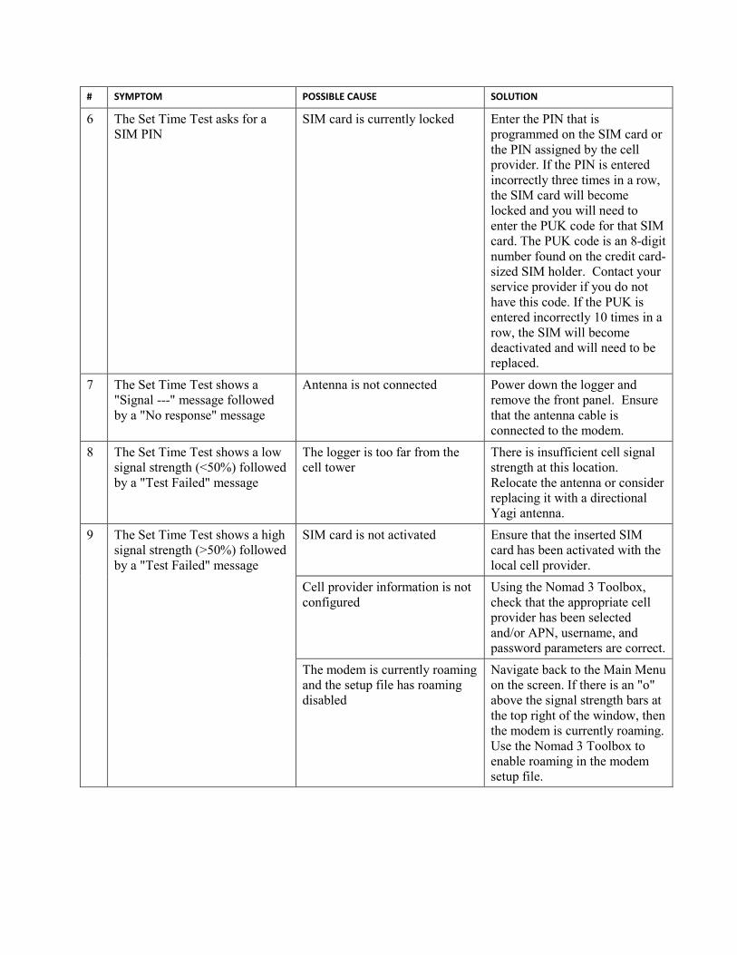
# SYMPTOM POSSIBLE CAUSE SOLUTION
6 The Set Time Test asks for a SIM PIN
SIM card is currently locked Enter the PIN that is programmed on the SIM card or the PIN assigned by the cell provider. If the PIN is entered incorrectly three times in a row, the SIM card will become locked and you will need to enter the PUK code for that SIM card. The PUK code is an 8-digit number found on the credit card-sized SIM holder. Contact your service provider if you do not have this code. If the PUK is entered incorrectly 10 times in a row, the SIM will become deactivated and will need to be replaced.
7 The Set Time Test shows a "Signal ---" message followed by a "No response" message
Antenna is not connected Power down the logger and remove the front panel. Ensure that the antenna cable is connected to the modem.
8 The Set Time Test shows a low signal strength (<50%) followed by a "Test Failed" message
The logger is too far from the cell tower
There is insufficient cell signal strength at this location. Relocate the antenna or consider replacing it with a directional Yagi antenna.
9 The Set Time Test shows a high signal strength (>50%) followed by a "Test Failed" message
SIM card is not activated Ensure that the inserted SIM card has been activated with the local cell provider.
Cell provider information is not configured
Using the Nomad 3 Toolbox, check that the appropriate cell provider has been selected and/or APN, username, and password parameters are correct.
The modem is currently roaming and the setup file has roaming disabled
Navigate back to the Main Menu on the screen. If there is an "o" above the signal strength bars at the top right of the window, then the modem is currently roaming. Use the Nomad 3 Toolbox to enable roaming in the modem setup file.

NOMAD 3 USER’S GUIDE
6-4 M211756EN-A
6.3.2 EMAIL Use this information to troubleshoot any failure modes after sending a teat email through the Nomad 3 display. # SYMPTOM POSSIBLE CAUSE SOLUTION
1 When sending a test email from the Email Menu, the Send Test Email command displays "No Response"
There is a problem with the modem
See section 6.3.1 for Modem troubleshooting.
The Nomad 3 is not configured to send emails
If the Nomad 3 has not been configured for sending emails, see section 4.5 for instructions.
2 When sending a test email from the Email Menu, the Send Test Email command displays "Sent OK" but the email has not arrived
The email is being filtered to the recipient’s spam folder
Check or have the recipient check their spam folder for e-mails coming from [email protected] and mark it as a safe sender
6.3.3 FTP Use this information to troubleshoot any failure modes after sending a test file by FTP through the Nomad 3 display.
# SYMPTOM POSSIBLE CAUSE SOLUTION
1 When sending a test file from the FTP Menu, the Send Test File command displays "No Response"
There is a problem with the modem
See section 6.3.1 for Modem troubleshooting.
The FTP setup file contains incorrect information
Navigate to the FTP Menu screen. Scroll down and record Server, Server Port, User, and Pass information. Check this information against the information on record for the target FTP server. If any errors are found, see section 4.6 for modifying the FTP setup file.
The FTP server is not active Contact the system administrator of the target FTP server to ensure that it is operational.

6.3.4 SKYSERVE Use this information to troubleshoot any failure modes after sending a server ping test through the Nomad 3 display. # SYMPTOM POSSIBLE CAUSE SOLUTION
1 The SkyServe Ping Test displays "No Response"
There is a problem with the modem
See section 6.3.1 for Modem troubleshooting.
The Nomad 3 is not activated on SkyServe
See Section 3.8.3 for instructions on how to activate the Nomad 3 on SkyServe.
6.4 DATA CONVERSION/ENCRYPTION Refer to this section to troubleshoot any issues when converting files in the Online Nomad 3 Toolbox. # SYMPTOM POSSIBLE CAUSE SOLUTION
1 When using the Online Nomad 3 Toolbox to convert a dayfile (.n3df) to .csv format, the Toolbox displays "Error: unable to find decryption setup"
The appropriate decryption file is not saved in your Toolbox work environment
If authorized, contact the user who encrypted the Nomad 3 and follow the instructions in Section 0. If decryption file has been lost or corrupted, contact [email protected] for further assistance.
6.5 EXPORTING FILES Refer to this section to troubleshoot issues related to exporting files from the Nomad 3 using the USB flash drive. # SYMPTOM POSSIBLE CAUSE SOLUTION
1 When exporting data, setup or log files from the Nomad 3, the window displays "Error during export"
The USB drive is at capacity Clear space on the USB drive from a computer and retry exporting the files.
The USB drive was pulled before power was cut during the last USB operation
Select the right softkey to EJECT the USB. Navigate to the System Menu Restart System. Under the System Restart menu, select Reboot System.

NOMAD 3 USER’S GUIDE
6-6 M211756EN-A
6.6 INPUTS & SENSORS Refer to this section to troubleshoot any issues related to sensor readings and sensor wiring. # SYMPTOM POSSIBLE CAUSE SOLUTION
1 Counter anemometer appears in GUI but reads 0.
Wrong type anemometer in Setup. Anemometers that use 12 volt power use 1.4 V Threshold. Self-powered anemometers use 0.0 V Threshold.
Revise and reload Input Setup file taking care to note Threshold. See section 4.9 to edit the setup file.
12 volt wiring error Check that sensor has 12 volt power. See Figure 3-17 for correct wiring.
2 Counter anemometer does not appear in the GUI
The Input Setup has not activated the Counter
Use Nomad Toolbox to create and load an Input Setup for the Counter
3 Reed switch anemometer reads 0.
Pull-up resistor missing. Reed switch anemometers need a 10 k-ohm resistor. See Figure 3-13 for correct wiring.
4 Wind vane reads correctly for North and South but East and West are reversed
Wiring error. The Vaisala PV-1 and NRG 200P sensors have different wiring.
Reverse 2.5V excitation and ground, then retest. See Figure 3-8 for Vaisala sensors and Figure 3-9 for NRG sensors.
5 Connecting a sensor causes a Ground Wiring Alert
Ground and Earth are short-circuited.
Check the sensor wiring with a volt/ohm meter. Sometimes a manufacturer will connect one of the lead wires to the body of a metal sensor and the metal tower, which will connect it to Earth ground. This lead wire should not be connected to Earth ground.
6 Temperature sensor readings do not make sense
Incorrect slope and offset scaling and or range. Analog sensors come in many ranges of full scale output: 0-1V, 0-2.5V, and 0-5V.
Check the exact model of your sensor and verify that the Nomad 3 is correctly setup for both range and scaling. See section 4.9 to edit the setup file.

# SYMPTOM POSSIBLE CAUSE SOLUTION
7 Temperature, humidity, or pressure sensor read correctly on the GUI, but the data is not correct.
These are wired to 12V switched power to save energy and a sample is recorded. Switched power is on continuously when the GUI is in "View Inputs" mode. During logging, if the power is not switched on long enough before the sample is taken, the sensor has not "settled" and the data is incorrect.
Change the input setup to increase the "warm-up" time, for example, from 3 seconds to 4 seconds. See section 4.9 to edit the setup file.
6.7 GPS Refer to this section to troubleshoot any issues related to the GPS module connected to the Nomad 3 input block. # SYMPTOM POSSIBLE CAUSE SOLUTION
1 GPS shows "No Response" in interface
The GPS module is wired improperly
See Figure 3-8 for the wiring diagram for the serial GPS module.
The GPS module is not getting sufficient signal
Check that the GPS module is mounted to the top or side of any enclosure and has clear visibility to the sky.
2 The GPS Status Menu is showing incorrect latitude, longitude, and elevation values when a GPS module is installed
The latitude, longitude, and elevation have been manually set with a Site setup file
A user can manually enter the latitude, longitude, and elevation in the Nomad 3 Toolbox and import a Site setup file to load the coordinates in the logger (see section 4.2). These values in the Site setup file will always override any readings from a GPS module. If you wish to use the values from the GPS module, create and import a new Site setup file with the Latitude, Longitude, and Elevation fields left blank or reset the Site setup to the factory default settings.

NOMAD 3 USER’S GUIDE
6-8 M211756EN-A
6.8 TIMEKEEPING Refer to the information in this section to troubleshoot issues related to timekeeping on the Nomad 3. # SYMPTOM POSSIBLE CAUSE SOLUTION
1 The time displayed on the Nomad 3 interface is inaccurate by several seconds (>10) to minutes
The GPS is not connecting and thus not correcting for time drift.
If the Nomad 3 is connected to a GPS module, it will regularly update its internal clock to correct any time drift. If the logger has a GPS module and the time is drifting, check the wiring of the GPS as shown in Figure 3-8.
The modem is not connecting and thus not correcting for time drift.
If the Nomad 3 is not connected to a GPS module, it will use the modem to correct the internal clock for any time drift. See section 6.3.1 for modem troubleshooting.
2 The hour of the time displayed on the Nomad 3 is inaccurate.
There is no UTC offset setup. By default, all timekeeping on the Nomad 3 is done in UTC. To add a UTC offset to the logger, look up the UTC offset for the site location of the Nomad 3 and refer to section 4.2 for instructions on loading a new Site Setup file. The UTC offset will only adjust the time displayed on the Nomad 3’s interface; data timestamps will always be recorded in UTC.

6.9 ENVIRONMENTAL The Nomad 3 has an IP65 rating which protects the electronics from the elements when installed in the field. Refer to this section if any environmental issues develop while using the Nomad 3. # SYMPTOM POSSIBLE CAUSE SOLUTION
1 Cable connectors will not fit through rubber glands
Gland hole too small Unscrew the gland nut and put aside Remove the rubber gland by pushing down on it from the inside of the logger Using a utility knife and safety gloves, carefully cut a slice down the length of the gland between the desired hole and the outer diameter of the gland Feed cable connector in the proper direction through the gland nut Using a flat-headed screwdriver, pry the slice open enough to fit the wire of the cable. Ensure that the cable connector is going in the desired direction. Using one thumb to hold the cable in the slice, gently work the rest of the wire through the slice so that it is fully resting in the gland Feed the cable connector through the gland housing, reinsert the rubber gland, and screw the gland nut back in to place
2 Condensation inside the logger Unused gland holes not plugged If any of the pre-drilled gland holes are not used, cut a 3 cm length of a wire approximately equal in diameter to the hole. Loosen the gland nut and insert the wire through the hole, plugging it. Retighten the gland nut.

NOMAD 3 USER’S GUIDE
6-10 M211756EN-A
# SYMPTOM POSSIBLE CAUSE SOLUTION
2 Condensation inside the logger (continued)
Too much moisture in logger If the logger is completely sealed and there is still moisture inside, placing a desiccant pack inside either the modem enclosure or the main chamber may help. Make every effort to install the desiccant and seal the logger shut in the driest conditions possible for maximum effectiveness.
Enclosure latch not shut completely
Check the black gland around the entire edge of the logger door to ensure nothing is wedged in the gap. Check the latch mechanism for any debris or damage. Ensure the latch is completely shut when leaving the site.

6.10 SKYSERVE NOMAD 3 ACCOUNT MANAGER Refer to this section to troubleshoot any issues pertaining to using the Nomad 3 Account Manager or Toolbox. # SYMPTOM POSSIBLE CAUSE SOLUTION
1 Cannot login to the Account Manager
Forgotten password If you have forgotten your password for the Account Manager page, click the "Forgot your password?" link below the Sign In button. On the next page, you will be prompted to enter your e-mail address. Once you enter the address and click "Send password reset instructions", SkyServe will send you an e-mail with further instructions for resetting your password.
2 Cannot activate the Nomad 3 The Nomad 3 has already been activated
Contact your company’s account manager or Vaisala support at [email protected] for help with your Nomad 3.

NOMAD 3 USER’S GUIDE
6-12 M211756EN-A
6.11 CONTACT INFORMATION AND ONLINE RESOURCES For additional support, please contact the Vaisala Support Services team: +1-888-VAISALA (Americas) +358-9-8949-2658 (Europe, Asia & Pacific) [email protected]

This page was intentionally left blank.

www.vaisala.com