No Time to Countdown: Migrating Backoff to the …srihari/pubs/Back2F_MobiCom11.pdfNo Time to...
12
No Time to Countdown: Migrating Backoff to the Frequency Domain Souvik Sen Duke University Durham, NC, USA [email protected] Romit Roy Choudhury Duke University Durham, NC, USA [email protected] Srihari Nelakuditi University of South Carolina Columbia, SC, USA [email protected] ABSTRACT Conventional WiFi networks perform channel contention in time domain. This is known to be wasteful because the chan- nel is forced to remain idle while all contending nodes are backing off for multiple time slots. This paper proposes to break away from convention and recreate the backing off op- eration in the frequency domain. Our basic idea leverages the observation that OFDM subcarriers can be treated as integer numbers. Thus, instead of picking a random backoff duration in time, a contending node can signal on a randomly cho- sen subcarrier. By employing a second antenna to listen to all the subcarriers, each node can determine whether its cho- sen integer (or subcarrier) is the smallest among all others. In fact, each node can even determine the rank of its chosen subcarrier, enabling the feasibility of scheduled transmissions after every round of contention. We develop these ideas into a Back2F protocol that migrates WiFi backoff to the frequency domain. Experiments on a prototype of 10 USRPs confirm fea- sibility, along with consistent throughput gains over 802.11. Trace based simulations affirm scalability to larger, real-world network topologies. Categories and Subject Descriptors C.2.1 [Network Architecture and Design]: Wireless commu- nication General Terms Design, Experimentation, Performance Keywords Wireless, Contention Resolution, Cross-Layer, Backoff Permission to make digital or hard copies of all or part of this work for personal or classroom use is granted without fee provided that copies are not made or distributed for profit or commercial advantage and that copies bear this notice and the full citation on the first page. To copy otherwise, to republish, to post on servers or to redistribute to lists, requires prior specific permission and/or a fee. MobiCom’11, September 19–23, 2011, Las Vegas, Nevada, USA. Copyright 2011 ACM 978-1-4503-0492-4/11/09 ...$10.00. 1. INTRODUCTION Access control strategies are designed to arbitrate how mul- tiple entities access a shared resource. Several distributed protocols embrace randomization to achieve arbitration. In WiFi networks, for example, each participating node picks a random number from a specified range and begins counting down. The node that finishes first, say N1, wins channel con- tention and begins transmission. The other nodes freeze their countdown temporarily, and revive it only after N1’s trans- mission is complete. Since every node counts down at the same pace, this scheme produces an implicit ordering among nodes. Put differently, the node that picks the smallest ran- dom number transmits first, the one that picks the second- smallest number transmits second, and so on. The overall operation is often termed as “backoff”. While backoff arbitrates channel contention, it incurs a per- formance cost. Specifically, when multiple nodes are simulta- neously backing off, the channel must remain idle, naturally leading to under-utilization. Moreover, network congestion prompts an exponential increase in the backoff range, intro- ducing the possibility of greater channel wastage. Authors in [16] show more than 30% reduction in throughput due to backing off; [13] shows the severity at higher data rates. This paper attempts to address this problem by migrating the backoff operation to the frequency domain. Our main idea is simple. When a node N1 has a packet to transmit, it picks a random value, r1, from a specified range [0,F ]. Once the channel becomes idle, N1 begins the back- off operation. However, instead of counting down from r1 to 0, N1 transmits a symbol on the r th 1 subcarrier 1 . We as- sume that each node has two antennas; thus, while one an- tenna transmits, the other antenna listens to determine which of the subcarriers are active. Assuming N2 is also contending for the channel, and say has transmitted on the r th 2 subcarrier, N1 observes activity on both subcarriers r1 and r2. Assuming r1 <r2, N1 immediately infers that it has won channel con- tention, and begins transmission. N2 learns that it has lost, and defers its own transmission until N1 has finished. We call this approach Back2F, as an acronym for migrating backoff to the frequency domain. The advantages of Back2F are two fold. First, one round of frequency domain backoff should ideally last for few OFDM symbols, substantially less than the average backoff in proto- 1 Subcarriers are narrowband OFDM channels used by 802.11.
Transcript of No Time to Countdown: Migrating Backoff to the …srihari/pubs/Back2F_MobiCom11.pdfNo Time to...
No Time to Countdown:Migrating Backoff to the Frequency Domain
Souvik SenDuke University
Durham, NC, [email protected]
Romit Roy ChoudhuryDuke University
Durham, NC, [email protected]
Srihari NelakuditiUniversity of South Carolina
Columbia, SC, [email protected]
ABSTRACTConventional WiFi networks perform channel contention intime domain. This is known to be wasteful because the chan-nel is forced to remain idle while all contending nodes arebacking off for multiple time slots. This paper proposes tobreak away from convention and recreate the backing off op-eration in the frequency domain. Our basic idea leverages theobservation that OFDM subcarriers can be treated as integernumbers. Thus, instead of picking a random backoff durationin time, a contending node can signal on a randomly cho-sen subcarrier. By employing a second antenna to listen toall the subcarriers, each node can determine whether its cho-sen integer (or subcarrier) is the smallest among all others.In fact, each node can even determine the rank of its chosensubcarrier, enabling the feasibility of scheduled transmissionsafter every round of contention. We develop these ideas intoa Back2F protocol that migrates WiFi backoff to the frequencydomain. Experiments on a prototype of 10 USRPs confirm fea-sibility, along with consistent throughput gains over 802.11.Trace based simulations affirm scalability to larger, real-worldnetwork topologies.
Categories and Subject DescriptorsC.2.1 [Network Architecture and Design]: Wireless commu-nication
General TermsDesign, Experimentation, Performance
KeywordsWireless, Contention Resolution, Cross-Layer, Backoff
Permission to make digital or hard copies of all or part of this work forpersonal or classroom use is granted without fee provided that copies arenot made or distributed for profit or commercial advantage and that copiesbear this notice and the full citation on the first page. To copy otherwise, torepublish, to post on servers or to redistribute to lists, requires prior specificpermission and/or a fee.MobiCom’11, September 19–23, 2011, Las Vegas, Nevada, USA.Copyright 2011 ACM 978-1-4503-0492-4/11/09 ...$10.00.
1. INTRODUCTIONAccess control strategies are designed to arbitrate how mul-tiple entities access a shared resource. Several distributedprotocols embrace randomization to achieve arbitration. InWiFi networks, for example, each participating node picks arandom number from a specified range and begins countingdown. The node that finishes first, say N1, wins channel con-tention and begins transmission. The other nodes freeze theircountdown temporarily, and revive it only after N1’s trans-mission is complete. Since every node counts down at thesame pace, this scheme produces an implicit ordering amongnodes. Put differently, the node that picks the smallest ran-dom number transmits first, the one that picks the second-smallest number transmits second, and so on. The overalloperation is often termed as “backoff”.
While backoff arbitrates channel contention, it incurs a per-formance cost. Specifically, when multiple nodes are simulta-neously backing off, the channel must remain idle, naturallyleading to under-utilization. Moreover, network congestionprompts an exponential increase in the backoff range, intro-ducing the possibility of greater channel wastage. Authorsin [16] show more than 30% reduction in throughput dueto backing off; [13] shows the severity at higher data rates.This paper attempts to address this problem by migrating thebackoff operation to the frequency domain.
Our main idea is simple. When a node N1 has a packet totransmit, it picks a random value, r1, from a specified range[0, F ]. Once the channel becomes idle, N1 begins the back-off operation. However, instead of counting down from r1to 0, N1 transmits a symbol on the rth1 subcarrier1. We as-sume that each node has two antennas; thus, while one an-tenna transmits, the other antenna listens to determine whichof the subcarriers are active. Assuming N2 is also contendingfor the channel, and say has transmitted on the rth2 subcarrier,N1 observes activity on both subcarriers r1 and r2. Assumingr1 < r2, N1 immediately infers that it has won channel con-tention, and begins transmission. N2 learns that it has lost,and defers its own transmission until N1 has finished. We callthis approach Back2F, as an acronym for migrating backoff tothe frequency domain.
The advantages of Back2F are two fold. First, one round offrequency domain backoff should ideally last for few OFDMsymbols, substantially less than the average backoff in proto-
1Subcarriers are narrowband OFDM channels used by802.11.

cols like 802.11. Second, Back2F creates a logical orderingamong contending nodes, and each node learns its own rankin this order. This ranking among nodes creates the possi-bility of batched transmissions, eliminating the need for per-packet backoff. Since 802.11 currently backs off before everypacket, Back2F helps improve the channel usage and networkthroughput.
Of course, extracting these gains entail a number of researchchallenges: (1) Active subcarriers need to be detected accu-rately in face of loose time synchronization among transmit-ters, energy leakage between narrow-band subcarriers, andchannel fading. (2) Collision among nodes – which hap-pens when multiple nodes choose the same subcarrier – needsto be mitigated successfully. (3) Finally, since nodes are lo-cated in different contention neighborhoods, the node rank-ings do not obey any global order. Back2F needs to copewith relative ranking among nodes, while maintaining spatialreuse and fairness comparable to 802.11. We address thesechallenges through activation of diverse subcarriers, multiplerounds of contention, and virtual countdown. We consolidatethese ideas into a protocol, and implement a prototype on theUSRP/ GNURadio platform. Experimental results show 95%accuracy in subcarrier detection, less than 2% probability ofcollision, and throughput gains of more than 35% at high bit-rates. Trace driven simulations (with topologies and channelconditions drawn from our university network) confirms sta-bility and scalability of Back2F to real-world scenarios.
Our contributions in this paper may be summarized as:
• We identify an opportunity to migrate protocol operationsfrom the time to the frequency domain. Although we in-stantiate our ideas through a WiFi based MAC, they maybe generalized to other arbitration strategies.
• We design an OFDM based system where random backoff isrealized by selectively transmitting on a subcarrier. A log-ical order among senders is enforced in a decentralizedmanner, for improved channel usage.
• We address the challenges behind such a scheme, and pro-totype it on the USRP/GNURadio platform. Promising re-sults, in terms of throughput, fairness, and scalability,give us confidence to build a larger system.
2. 802.11 AND OFDMThis section highlights the limitations of 802.11’s backoff (intime domain), and presents a simple abstraction of OFDM (tobetter explain the shift to frequency domain).
802.11 Channel Access: WiFi prescribes each transmitter tobackoff for a random number of slots, chosen from the range[0, CW − 1], where CW is the contention window. Each timeslot corresponds to 9µs. The node counts down only if thechannel is idle – if the node senses a busy channel, the count-down is frozen, and revived only after the channel is idle.Whichever node completes the countdown first begins trans-mission. When this transmission is complete, the other nodeswait for a DIFS duration, and continue with their remain-ing countdown. Observe that 802.11 implicitly forms a queueamong contending nodes, each node’s position in the queue de-termined by the random number it chooses. Prior analyses haveshown that this scheme guarantees stability and fairness [6].
We make three observations that are not necessarily new. (1)Fundamentally, backing off is not a time domain operation.Its implementation is in the time domain, forcing the chan-nel to be idle before each packet transmission. (2) The du-ration of each backoff slot is fixed, so the channel wastagegrows with smaller packets and higher bitrates. A packet’sairtime is shorter at higher rates, and hence, the fractionof channel-time occupied by idle slots is larger. (3) Finally,although channel utilization may improve with few nodes(backing off in parallel), just a few more nodes can cause col-lisions (802.11 experiences 18% collisions with 3 nodes andCW=16). A collision forces nodes to exponentially increasetheir backoff, pushing the system back to under-utilization.Fig. 1 shows the channel under-utilization due to 802.11’sbackoff, under varying bitrates and network densities. Au-thors in [16, 29] corroborate these findings with extensiveanalysis and measurements, emphasizing the need to improvewireless contention resolution.
0
0.05
0.1
0.15
0.2
0.25
0.3
0.35
0.4
0.45
10 15 20 25 30 35 40 45 50 55Ch
ann
el w
aste
du
e to
bac
ko
ff(%
)
Bitrate in Mbps
2 APs 512 bytes6 APs 512 bytes
10 APs 512 bytes2 APs 1024 bytes6 APs 1024 bytes
10 APs 1024 bytes
Figure 1: Overhead of 802.11 backoff. Larger fraction ofchannel wasted with smaller packets at higher bitrates.
Orthogonal Frequency Division Multiplexing: OFDM canbe abstracted as a PHY scheme that divides the wireless spec-trum into multiple narrow band channels, called subcarriers.The subcarriers carry modulated data streams in parallel, butat a lower rate per-subcarrier. The benefit of OFDM emergesfrom its ability to cope with channel adversities, includingnarrowband interference and frequency-selective fading dueto multipath. The 802.11a/g implementation of OFDM has52 subcarriers, of which 48 are used for data transmission,and 4 for equalization. A transmitter stripes bits across allsubcarriers, however, it is possible to transmit/receive onlyon a subset of them.
As we will see later, a Back2F node picks a random number,say 11, and transmits a short signal only on the 11th subcar-rier. The node’s second antenna detects a strong signal on the11th subcarrier, as well as on other subcarriers used by othercontending nodes. Practical hardware constraints raise diffi-culties in discriminating between adjacent subcarriers. Whenthe second antenna receives a strong signal on the 11th sub-carrier, “leakage” into adjacent subcarriers may mislead thereceiver into detecting subcarriers 10 and 12 also as active.Higher point FFTs are useful to mitigate such effects – the
spikes on subcarriers can be better isolated. Migrating to thefrequency domain brings these problems, and Back2F needsto handle them.
3. ARCHITECTURE AND DESIGNWe present Back2F in 3 sub-parts. First, we describe thescheme under the assumption of a single collision domain(i.e., all nodes can hear each other). Second, we relax theassumption, and describe how the approach can be extendedto networks with multiple collision domains. Finally, we ex-plore optimizations to support batched transmissions, obviat-ing the need to perform per-packet contention. The sectionconcludes with discussion about practical challenges in real-izing Back2F and techniques to overcome them.
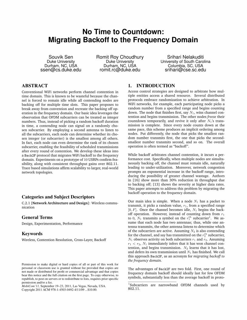
3.1 Backoff within a Single Collision DomainFigure 2 shows an example where contenders AP1 and AP2choose random numbers 11 and 29, respectively. However, in-stead of counting down these numbers in time, they transmita short signal on their corresponding subcarriers. While thesignal is being transmitted on the transmit antenna, a listen-ing antenna on each AP receives the combined signals fromall the APs, as well as its own signal, called the self-signal.The listening antenna then extracts all the active subcarriers,thereby learning the backoff values of the other contenders.With knowledge of everyone’s backoffs, each AP can instan-taneously determine whether it has won the contention. If itsown backoff is smaller than all others, it proceeds with datatransmission; otherwise, it defers to a later time. Of course,data transmission is performed using all the subcarriers, iden-tical to regular 802.11 operation.
Figure 2: A close up view of the first backoff. AP1picks/activates subcarrier 11 and AP2 chooses 29. Theylearn of other backoff values through subcarriers. AP1with smaller backoff transmits whereas AP2 defers.
The signaling on subcarriers happen synchronously. Synchro-nization is achieved implicitly [28], i.e., both APs observe thesame channel, and hence, when the channel becomes idle,both APs recognize it as a trigger to begin transmission. Ofcourse, the synchronization may not be perfect due to differ-ences in signal propagation delays. Subsection 3.5 discussesways to cope with the problem.
In the above example, both AP1 and AP2 learn that the back-off values of all the contending nodes are 11 and 29. AP1 with
smaller backoff of 11 proceeds to transmit, whereas AP2 withlarger backoff defers. The deferred node deducts the smallestknown backoff and contends again after the channel has be-come idle, i.e., after AP1 finishes, AP2 contends with a backoffvalue of 29 − 11 = 18. Observe that the net effect is exactlylike time-domain backoff in 802.11. All the contending nodescount down simultaneously till the smallest of them reacheszero; the node whose backoff reaches zero proceeds to trans-mit, while others contend later with their reduced backoffvalues. However, unlike 802.11, the time to pick a winnerin Back2F is much shorter, in the order of few OFDM sym-bols. Algorithm 1 summarizes the essence of Back2F througha pseudocode.
Algorithm 1 : Basic operation of Back2F(pkt)1: myback← random(0, maxback)2: wait for the channel to be idle for DIFS duration3: transmit on subcarrier myback4: in parallel, listen for active subcarriers (allbacks)5: myback← myback −min{allbacks}6: if myback 6= 0 then goto line 27: transmit pkt
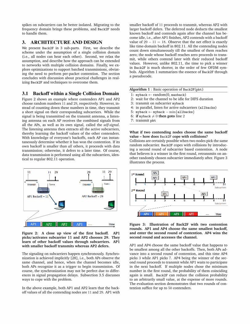
What if two contending nodes choose the same backoffvalue – how does Back2F cope with collisions?Collisions are certainly possible when two nodes pick the samerandom subcarrier. Back2F copes with collisions by introduc-ing a second round of subcarrier based contention. A nodethat believes is a winner in the first round, retransmits on an-other randomly chosen subcarrier immediately after. Figure 3illustrates the process.
Figure 3: Illustration of Back2F with two contentionrounds. AP1 and AP4 choose the same smallest backoff,and enter the second round of contention. AP4 wins thesecond round and accesses the channel.
AP1 and AP4 choose the same backoff value that happens tobe smallest among all the other backoffs. Then, both APs ad-vance into a second round of contention, and this time AP4picks 3 while AP1 picks 7. AP4 being the winner of the sec-ond round proceeds to transmit while AP1 waits to participatein the next backoff. If multiple nodes chose the minimumnumber in the first round, the probability of them coincidingagain is small. Back2F can reduce the collision probabilityto an arbitrarily small value, at the expense of more rounds.The evaluation section demonstrates that two rounds of con-tention suffice for up to 50 contenders.
Once the winning node completes transmission, all the losingnodes (AP1, AP2, and AP3) contend for the next opportunityto access the channel. However, instead of choosing a newbackoff, they revise their prior backoff (as mentioned earlier).Figure 4 illustrates this as a follow up to Figure 3. The small-est backoff of 2 from the first round is deducted from eachnode’s backoff. Thus, the resulting backoffs of AP1, AP2, andAP3 are 0, 3, and 6, respectively, which they now use for con-tention2.
Figure 4: AP1, AP2, and AP3 lost the contention in Fig-ure 3, hence, reduce their backoffs by 2 (i.e., AP4’s firstround backoff value). This reduction emulates (virtual)elapsing of 2 time slots due to AP4’s countdown. AfterAP4 finishes, AP1, AP2, and AP3 contend with these re-vised backoff values. AP1 wins this time and transmits.
Ideally, Back2F should recognize that AP1 is the sole winner inFigure 4, and obviate the need for a second round of transmis-sion. Unfortunately, there is no way to reliably tell between asole winner and collisions. This is because a Back2F node candetect which subcarriers are active, but cannot tell how manynodes transmitted on a given subcarrier. Hence, we proposeto always perform two rounds of contention, though it is sub-optimal. As a result, only AP1 advances to the second roundin Figure 4, obviously wins the contention, and proceeds totransmit its packet.
Algorithm 2 presents the pseudo code for two-round Back2F.Lines 1−6 correspond to the first round and 7−10 reflect thesecond round. If a node loses in the second round, it behavesjust like it would after losing in the first round. It goes backto line 2 to contend later with a revised backoff as in line 5.Again, note that the second round is only meant to break ties,while the transmission order is solely based on the backoffvalues chosen in the first round.
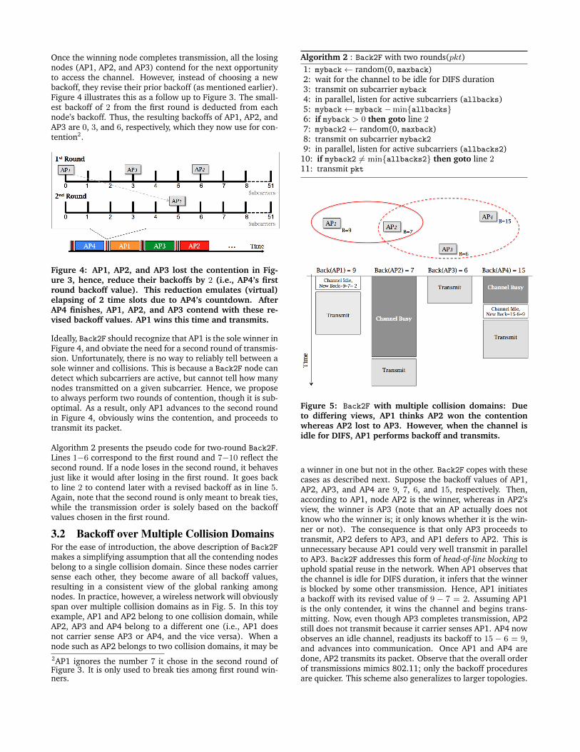
3.2 Backoff over Multiple Collision DomainsFor the ease of introduction, the above description of Back2Fmakes a simplifying assumption that all the contending nodesbelong to a single collision domain. Since these nodes carriersense each other, they become aware of all backoff values,resulting in a consistent view of the global ranking amongnodes. In practice, however, a wireless network will obviouslyspan over multiple collision domains as in Fig. 5. In this toyexample, AP1 and AP2 belong to one collision domain, whileAP2, AP3 and AP4 belong to a different one (i.e., AP1 doesnot carrier sense AP3 or AP4, and the vice versa). When anode such as AP2 belongs to two collision domains, it may be2AP1 ignores the number 7 it chose in the second round ofFigure 3. It is only used to break ties among first round win-ners.
Algorithm 2 : Back2F with two rounds(pkt)1: myback← random(0, maxback)2: wait for the channel to be idle for DIFS duration3: transmit on subcarrier myback4: in parallel, listen for active subcarriers (allbacks)5: myback← myback −min{allbacks}6: if myback > 0 then goto line 27: myback2← random(0, maxback)8: transmit on subcarrier myback29: in parallel, listen for active subcarriers (allbacks2)
10: if myback2 6= min{allbacks2} then goto line 211: transmit pkt
Figure 5: Back2F with multiple collision domains: Dueto differing views, AP1 thinks AP2 won the contentionwhereas AP2 lost to AP3. However, when the channel isidle for DIFS, AP1 performs backoff and transmits.
a winner in one but not in the other. Back2F copes with thesecases as described next. Suppose the backoff values of AP1,AP2, AP3, and AP4 are 9, 7, 6, and 15, respectively. Then,according to AP1, node AP2 is the winner, whereas in AP2’sview, the winner is AP3 (note that an AP actually does notknow who the winner is; it only knows whether it is the win-ner or not). The consequence is that only AP3 proceeds totransmit, AP2 defers to AP3, and AP1 defers to AP2. This isunnecessary because AP1 could very well transmit in parallelto AP3. Back2F addresses this form of head-of-line blocking touphold spatial reuse in the network. When AP1 observes thatthe channel is idle for DIFS duration, it infers that the winneris blocked by some other transmission. Hence, AP1 initiatesa backoff with its revised value of 9 − 7 = 2. Assuming AP1is the only contender, it wins the channel and begins trans-mitting. Now, even though AP3 completes transmission, AP2still does not transmit because it carrier senses AP1. AP4 nowobserves an idle channel, readjusts its backoff to 15 − 6 = 9,and advances into communication. Once AP1 and AP4 aredone, AP2 transmits its packet. Observe that the overall orderof transmissions mimics 802.11; only the backoff proceduresare quicker. This scheme also generalizes to larger topologies.

3.3 Coping with Misdetection due to FadingA natural question is how does subcarrier misdetection (falsepositives and negatives) affect the performance of Back2F? Con-sider a false positive where a node falsely detects a subcar-rier f even though no one has transmitted on that subcarrier(while it is unlikely to find energy on a subcarrier in the ab-sence of an actual transmission, we still consider this case forcompleteness). Observe that such a false positive does notaffect Back2F, so long as f is not the smallest-valued subcar-rier – the winner – among the contenders. When f is indeedthe smallest, a false positive can mislead the (actual) winnerto unnecessarily wait for a non-existent transmission. Thewait, however, is bounded by DIFS – once the actual winnerobserves an idle channel for DIFS, it initiates backoff and sub-sequent operations. Thus, a false positive may, in some cases,cause the channel to be wasted for a DIFS duration.
Now consider the more likely case where a node with self-subcarrier i fails to detect a legitimate subcarrier f , i.e., afalse negative. Again, a false negative has no effect whennumber i is less than f – in this case, i will still correctly de-tect that it has won the contention. Even if i is greater than f ,the impact may not be severe if this occurs in the first round.This is because imay believe it is the winner of the first round,and advance to the second to contend again. However, if fis smaller than i in the second round, then the node withself-subcarrier i will wrongly assume itself to be the winner,causing a certain collision. This is a serious consequence of afalse negative since it defeats the purpose of backing off.
We believe (and will evaluate later) that only under some re-stricted conditions discussed above, will false negatives affectperformance. Nevertheless, we propose the following to al-leviate the impact of false negatives. The main observationis that false negatives are of concern only in the second roundof contention, and that the second round typically has a fewnodes contending. This suggests that fewer (than 52) sub-carriers may be adequate to select the winner among them.Thus, instead of transmitting on a single subcarrier, a nodecan transmit on multiple subcarriers on different parts of thefrequency spectrum. For instance, a node that has picked arandom number i, can transmit on subcarriers i and ((F
2+ i)
mod F ), where F is the total number of subcarriers. Giventhat these two subcarriers would be separated in frequency,they may observe dissimilar fading patterns, making at leastone of them detectable (Figure 6). Further, subcarrier detec-tion thresholds may also be tuned to lower false negativesat the expense of less-expensive false positives. We evaluatethe overall impact of subcarrier misdetection in Sec. 4, anddemonstrate that the performance is not overly sensitive.
3.4 Optimization: Batched TransmissionsUnlike 802.11, Back2F enables each node to learn its ranka priori in the sequence of pending transmissions. In fact,each node also knows the exact backoff values chosen byother nodes (although the mapping between node ID and back-off value is not known). Back2F aims to exploit this knowledgeto batch transmissions (i.e., a train of back-to-back packetsbetween successive backoffs). A node ranked n can transmitimmediately after the (n − 1)th ranked node finishes trans-mission. The protocol structure is as follows.
Figure 6: Signaling on subcarriers i and 26 + i in the sec-ond round to alleviate the impact of false negatives.
Batch size and transmission order.As a first step, Back2F promotes the top-K ranked APs to thesecond round, as opposed to the winner(s) alone. The choiceof K brings out a tradeoff between collision probability andbatch size. Higher values of K will result in longer batchsize (better throughput), but at the risk of collisions. Weset K = 3 in our implementation, empirically observed toprovide the best tradeoff. Given the choice of K, each nodeknows whether it is top-K ranked after the first round of con-tention. Those that are, proceed to the second round, whileothers do not. As an example, suppose 4 APs in Figure 7 con-tend in the first round, and the protocol intends to promotethe top-2 ranked APs to the second round. AP1 and AP4, bothranked 1, naturally advance; AP3 also advances because it isranked 2. These three nodes are then ordered as AP4, AP3,AP1 in their second round of contention, and they transmitback-to-back in that sequence, without a per-packet backoff.
Figure 7: Backoff in the frequency domain followed byscheduled transmissions. All APs contend in the firstround, but only AP1 and AP2 enter the second round.Based on backoff values in the second round, the scheduleis AP1 followed by AP2. Only after the scheduled trans-missions complete, AP3 and AP4 contend again.
Of course, Back2F cannot guarantee that exactlyK nodes willproceed to the second round – “top-K ranked nodes” may im-ply more than K nodes. However, by observing the activesubcarriers in the first round, each node can probabilisticallyestimate how many nodes have picked the same subcarrier.The promotion to the second round may be guided by thisestimation. Thus, if the protocol desires 5 nodes in the sec-ond round, and probabilistic estimates suggest 1.25 nodes onaverage per subcarrier, nodes ranked 4 or less can proceed tothe second round. Each contending node can make this deci-sion independently.
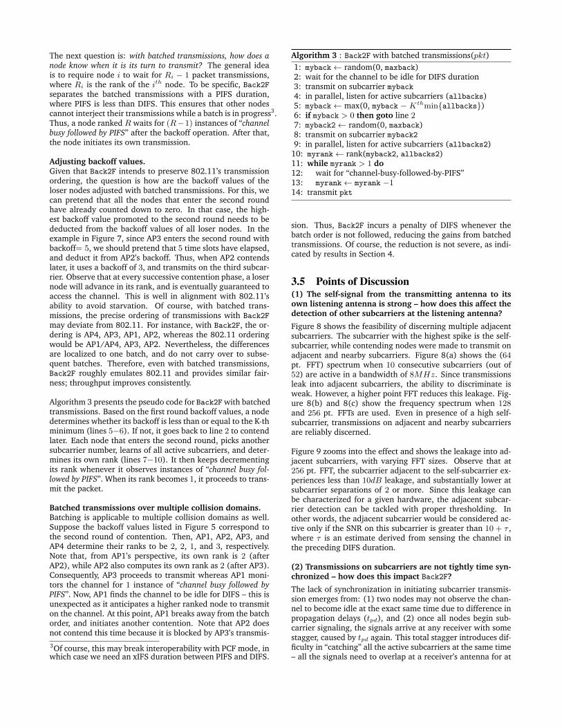
The next question is: with batched transmissions, how does anode know when it is its turn to transmit? The general ideais to require node i to wait for Ri − 1 packet transmissions,where Ri is the rank of the ith node. To be specific, Back2Fseparates the batched transmissions with a PIFS duration,where PIFS is less than DIFS. This ensures that other nodescannot interject their transmissions while a batch is in progress3.Thus, a node ranked R waits for (R−1) instances of “channelbusy followed by PIFS” after the backoff operation. After that,the node initiates its own transmission.
Adjusting backoff values.Given that Back2F intends to preserve 802.11’s transmissionordering, the question is how are the backoff values of theloser nodes adjusted with batched transmissions. For this, wecan pretend that all the nodes that enter the second roundhave already counted down to zero. In that case, the high-est backoff value promoted to the second round needs to bededucted from the backoff values of all loser nodes. In theexample in Figure 7, since AP3 enters the second round withbackoff= 5, we should pretend that 5 time slots have elapsed,and deduct it from AP2’s backoff. Thus, when AP2 contendslater, it uses a backoff of 3, and transmits on the third subcar-rier. Observe that at every successive contention phase, a losernode will advance in its rank, and is eventually guaranteed toaccess the channel. This is well in alignment with 802.11’sability to avoid starvation. Of course, with batched trans-missions, the precise ordering of transmissions with Back2F
may deviate from 802.11. For instance, with Back2F, the or-dering is AP4, AP3, AP1, AP2, whereas the 802.11 orderingwould be AP1/AP4, AP3, AP2. Nevertheless, the differencesare localized to one batch, and do not carry over to subse-quent batches. Therefore, even with batched transmissions,Back2F roughly emulates 802.11 and provides similar fair-ness; throughput improves consistently.
Algorithm 3 presents the pseudo code for Back2F with batchedtransmissions. Based on the first round backoff values, a nodedetermines whether its backoff is less than or equal to the K-thminimum (lines 5−6). If not, it goes back to line 2 to contendlater. Each node that enters the second round, picks anothersubcarrier number, learns of all active subcarriers, and deter-mines its own rank (lines 7−10). It then keeps decrementingits rank whenever it observes instances of “channel busy fol-lowed by PIFS”. When its rank becomes 1, it proceeds to trans-mit the packet.
Batched transmissions over multiple collision domains.Batching is applicable to multiple collision domains as well.Suppose the backoff values listed in Figure 5 correspond tothe second round of contention. Then, AP1, AP2, AP3, andAP4 determine their ranks to be 2, 2, 1, and 3, respectively.Note that, from AP1’s perspective, its own rank is 2 (afterAP2), while AP2 also computes its own rank as 2 (after AP3).Consequently, AP3 proceeds to transmit whereas AP1 moni-tors the channel for 1 instance of “channel busy followed byPIFS”. Now, AP1 finds the channel to be idle for DIFS – this isunexpected as it anticipates a higher ranked node to transmiton the channel. At this point, AP1 breaks away from the batchorder, and initiates another contention. Note that AP2 doesnot contend this time because it is blocked by AP3’s transmis-3Of course, this may break interoperability with PCF mode, inwhich case we need an xIFS duration between PIFS and DIFS.
Algorithm 3 : Back2F with batched transmissions(pkt)1: myback← random(0, maxback)2: wait for the channel to be idle for DIFS duration3: transmit on subcarrier myback4: in parallel, listen for active subcarriers (allbacks)5: myback← max(0, myback − Kthmin{allbacks})6: if myback > 0 then goto line 27: myback2← random(0, maxback)8: transmit on subcarrier myback29: in parallel, listen for active subcarriers (allbacks2)
10: myrank← rank(myback2, allbacks2)11: while myrank > 1 do12: wait for “channel-busy-followed-by-PIFS”13: myrank← myrank −114: transmit pkt
sion. Thus, Back2F incurs a penalty of DIFS whenever thebatch order is not followed, reducing the gains from batchedtransmissions. Of course, the reduction is not severe, as indi-cated by results in Section 4.
3.5 Points of Discussion(1) The self-signal from the transmitting antenna to itsown listening antenna is strong – how does this affect thedetection of other subcarriers at the listening antenna?
Figure 8 shows the feasibility of discerning multiple adjacentsubcarriers. The subcarrier with the highest spike is the self-subcarrier, while contending nodes were made to transmit onadjacent and nearby subcarriers. Figure 8(a) shows the (64pt. FFT) spectrum when 10 consecutive subcarriers (out of52) are active in a bandwidth of 8MHz. Since transmissionsleak into adjacent subcarriers, the ability to discriminate isweak. However, a higher point FFT reduces this leakage. Fig-ure 8(b) and 8(c) show the frequency spectrum when 128and 256 pt. FFTs are used. Even in presence of a high self-subcarrier, transmissions on adjacent and nearby subcarriersare reliably discerned.
Figure 9 zooms into the effect and shows the leakage into ad-jacent subcarriers, with varying FFT sizes. Observe that at256 pt. FFT, the subcarrier adjacent to the self-subcarrier ex-periences less than 10dB leakage, and substantially lower atsubcarrier separations of 2 or more. Since this leakage canbe characterized for a given hardware, the adjacent subcar-rier detection can be tackled with proper thresholding. Inother words, the adjacent subcarrier would be considered ac-tive only if the SNR on this subcarrier is greater than 10 + τ ,where τ is an estimate derived from sensing the channel inthe preceding DIFS duration.
(2) Transmissions on subcarriers are not tightly time syn-chronized – how does this impact Back2F?
The lack of synchronization in initiating subcarrier transmis-sion emerges from: (1) two nodes may not observe the chan-nel to become idle at the exact same time due to difference inpropagation delays (tpd), and (2) once all nodes begin sub-carrier signaling, the signals arrive at any receiver with somestagger, caused by tpd again. This total stagger introduces dif-ficulty in “catching” all the active subcarriers at the same time– all the signals need to overlap at a receiver’s antenna for at

10 20 30 40 50 600
10
20
30
40
50
60
Subcarrier Number
SN
R in
dB
64 pt. FFT
10 20 30 40 50 600
10
20
30
40
50
60
SN
R in
dB
Subcarrier Number
128 pt. FFT
10 20 30 40 50 600
10
20
30
40
50
60
SN
R in
dB
Subcarrier Number
256 pt. FFT
Figure 8: Active subcarrier detection when 10 nodes transmitting with 64pt IFFT using 8MHz bandwidth. Receiver using(a) 64pt FFT; (b) 128pt FFT; (c) 256 pt FFT. All active subcarriers are clearly discernible with higher pt. FFT
0 1 2 3 4 5
0
20
40
60
Distance from Self Subcarrier
SN
R in d
B
64 pt. FFT
128 pt. FFT
256 pt. FFT
Figure 9: Effect of self signal on adjacent subcarriers. Ef-fect is low (<10dB) for every consecutive, 2nd and 4thsubcarrier for 256, 128, 64 pt. FFT respectively.
least one FFT window. Back2F copes with this problem byrequiring the subcarrier signaling to occur for slightly longerduration than one OFDM symbol. This longer duration in-cludes the maximum difference between propagation delays(= 2tpd), time for the FFT computation, a hardware circuitdelay, and guard factors. With tpd = 1µs in WLANs [10],64pt FFT taking 3.2µs at 20MHz, and circuit delay of 3µs, tworounds of Back2F contention incurs 16.4µs. This is apprecia-bly smaller than time domain backoff, varying uniformly be-tween 9µs to 135µs.
(3) Are 52 subcarriers and 2 rounds of contention ade-quate to cope with collision in high density scenarios?
Figure 10 shows the collision probability with increasing num-ber of contenders. Observe that when using 52 subcarriers,the collision probability increases quickly with a single roundof contention, and in fact, is worse than 802.11. However,promoting the winners of the first round to the second, dras-tically reduces the collision probability. Evidently, even whenthe number of contenders is more than 50 (a rare scenarioin WiFi networks), the collision probability still remains lessthan 2%. 802.11, on the other hand, collides far more fre-quently, and adapts through exponentially increasing its con-tention window. Naturally, waiting for exponentially longerdurations, incurs a performance penalty
0
0.1
0.2
0.3
0.4
0.5
0.6
0.7
5 10 15 20 25 30 35 40 45 50
Coll
isio
n P
robab
ilit
y(%
)
Number of APs
Back2F: 2 roundsBack2F: single round
802.11
Figure 10: Collision probability of Back2F with two roundsremains below 2% in high density networks with 52 sub-carriers. 802.11 experiences more collisions.
4. IMPLEMENTATION AND EVALUATIONThis section is organized to answer two main questions: (1)the reliability of subcarrier detection in an actual prototypenetwork, and (2) Back2F’s performance gain in realistic net-work topologies. We begin the discussion with a descriptionof our prototype testbed.
4.1 USRP/GNURadio PrototypeWe prototype Back2F on a small testbed of 10 USRPs – eachtransmitter formed by placing two USRPs adjacent to eachother, with a separation of ≈ 20 inches4. The strong self-signal is at 60dB. The transmitter transmits on a 8MHz band,while the listening antenna samples the same 8MHz channel,at the same center frequency. The transmitter is equippedto transmit on any of the 52 subcarriers, that are convertedinto a time domain signal using 64pt IFFT. The listening an-tenna can execute 64, 128, 256 point FFTs5. We show thatthe detection accuracy improves with FFT size. Note that this
4This distance can be reduced significantly without increasingthe self-signal [9] – we have not adopted this optimization.5The listening antenna may not be viewed as an additionalwireless interface. It only performs FFT and energy detectionper subcarrier.

requirement is specific to USRPs since the current 802.11a/gOFDM designs on USRPs need higher FFT sizes due to im-precision [26, 31]. We believe commercial hardware offersgreater precision, obviating the need for higher FFT sizes atthe listener.
The listening antenna detects subcarriers using a joint thresh-olding and peak-detection scheme. This is necessary becausewith practical hardware (especially USRPs), the subcarriersemerge as peaks rather than ideal impulses (Figure 8). When-ever a peak is above a threshold, Back2F declares it as an ac-tive subcarrier. Since backoff is always preceded by a DIFS in-terval in which the channel is idle, this threshold is adaptivelychosen by sampling the noise and interference floor over thisinterval. This helps in keeping the false positives/negativeslow.
Subcarrier Detection: The feasibility of detecting a subcar-rier, in presence of a strong self-signal, is the problem of inter-est. In the test, transmitters were randomly placed and madeto transmit signals on subcarriers at varying spectral separa-tion from the self-subcarrier. Figure 11 shows the detectionaccuracy (1− FalseNegative) as a function of subcarrier dis-tance from the self-subcarrier. As anticipated, the influenceof the self-signal reduces with increasing distance. Also, withincreasing FFT size at the listening antenna, even the nearbysubcarriers can be detected more accurately. Using a 256 ptFFT, subcarriers above 14dB can be detected reliably. OFDMbased carrier sense threshold in 802.11g/n permits transmis-sion when the signal in the channel is 13dB or below in com-parison to the noise floor [1, 8]; thus Back2F will almost beable to detect all links that are within the collision domain.Occasional false negatives may still happen, however, as weshow later, Back2F is reasonably robust to such occurrences.
Impact of noise and interference: Back2F is most vulner-able to misdetection on the subcarrier adjacent to the self-subcarrier. Hence, we focus on the detection of this subcar-rier to investigate the worst case performance of Back2F. Fig-ure 12(a) shows the false negatives in detecting the adjacentsubcarrier with 256pt FFT, for varying SNR of the signal onthat subcarrier. It also shows the false positives, i.e., incor-rectly detecting an inactive subcarrier. Clearly, false positivesare rare, less than 2%. As the SNR of the signal on the ad-jacent subcarrier increases, the possibility of false negativesdecreases, and at 14dB or more, it can be detected reliably.
Figure 12(b) also shows that background interference doesnot affect our results. Back2F does not falsely detect back-ground interference as an active subcarrier because it adjustsits threshold (as explained above) depending on energy per-subcarrier estimated during the idle DIFS. We believe that athigher bandwidths (20MHz in 802.11), Back2F’s detectionaccuracy may improve as a consequence of greater spectralseparation between subcarriers. Due to limitations in the pro-cessing capability of USRPs, the experiments in this paper areperformed at 8MHz bandwidth, but with all 52 subcarriers asin 802.11. Moreover, results presented later show that Back2Fcan tolerate some incidence of false negatives.
4.2 Trace based Performance EvaluationThe above USRP/GNURadio based prototype is suitable fordemonstrating the feasibility of active subcarrier detection,
3 4 5 6 7 80
0.2
0.4
0.6
0.8
1
Distance in Subcarriers
Dete
ction A
ccura
cy
8dB SNR
10dB SNR
12dB SNR
14dB SNR
16dB SNR
1 2 3 4 5 6 7 80
0.2
0.4
0.6
0.8
1
Distance in Subcarrier
Dete
ction A
ccura
cy
8dB SNR
10dB SNR
12dB SNR
14dB SNR
16dB SNR
1 2 3 4 5 6 7 80
0.2
0.4
0.6
0.8
1
Distance in Subcarriers
Dete
ction A
ccura
cy
8dB SNR
10dB SNR
12dB SNR
14dB SNR
16dB SNR
Figure 11: Detection accuracy of subcarriers at varyingdistance from the self subcarrier: Transmitter uses 64ptIFFT while listening antenna employs (a) 64, (b) 128, or(b) 256 pt FFT. With 256pt FFT, adjacent subcarriers withSNR 14dB or greater can be detected with 97% accuracy.Similar results for 128pt and 64pt FFT but at a higherseparation. With 128pt and 64pt FFT, we can use every2nd and 4th subcarrier respectively for Back2F.
but not the resulting gain from Back2F. Latency constraintswith the USRP platform disallow realtime implementation ofall the Back2F protocol operations. Therefore, we resort totrace based evaluation to assess performance in realistic sce-narios.
Evaluation setting: To conduct high fidelity emulation of realworld setting, we collected traces of channel characteristicsand network traffic as follows. We placed APs in 20 locationsand clients in 45 locations throughout our engineering build-ing. To gather information per subcarrier, we use Intel 5300chipset based wireless cards [2]. For each AP to client link, werecorded the RSSI, channel impulse response, transmissionbitrate, and collision probability with respect to the strongestinterfering AP. The transmission bitrate is experimentally se-lected as the highest bitrate that can support a delivery ratioof 90% or more. To estimate collision probability, we turn offcarrier sensing at the APs and activate downlink transmissionsin pairs. The collision probability is experimentally calculatedwith 10 runs of 500 packets of size 1500 bytes. We also gath-
8 10 12 14 16 18
0.1
0.3
0.5
0.7
0.91
SNR in dB
Fals
e p
ositiv
e/n
egative
False + False −
8 10 12 14 16 180
0.1
0.3
0.5
0.7
0.91
SNR in dB
Fals
e p
ositiv
e/n
egative
False + False −
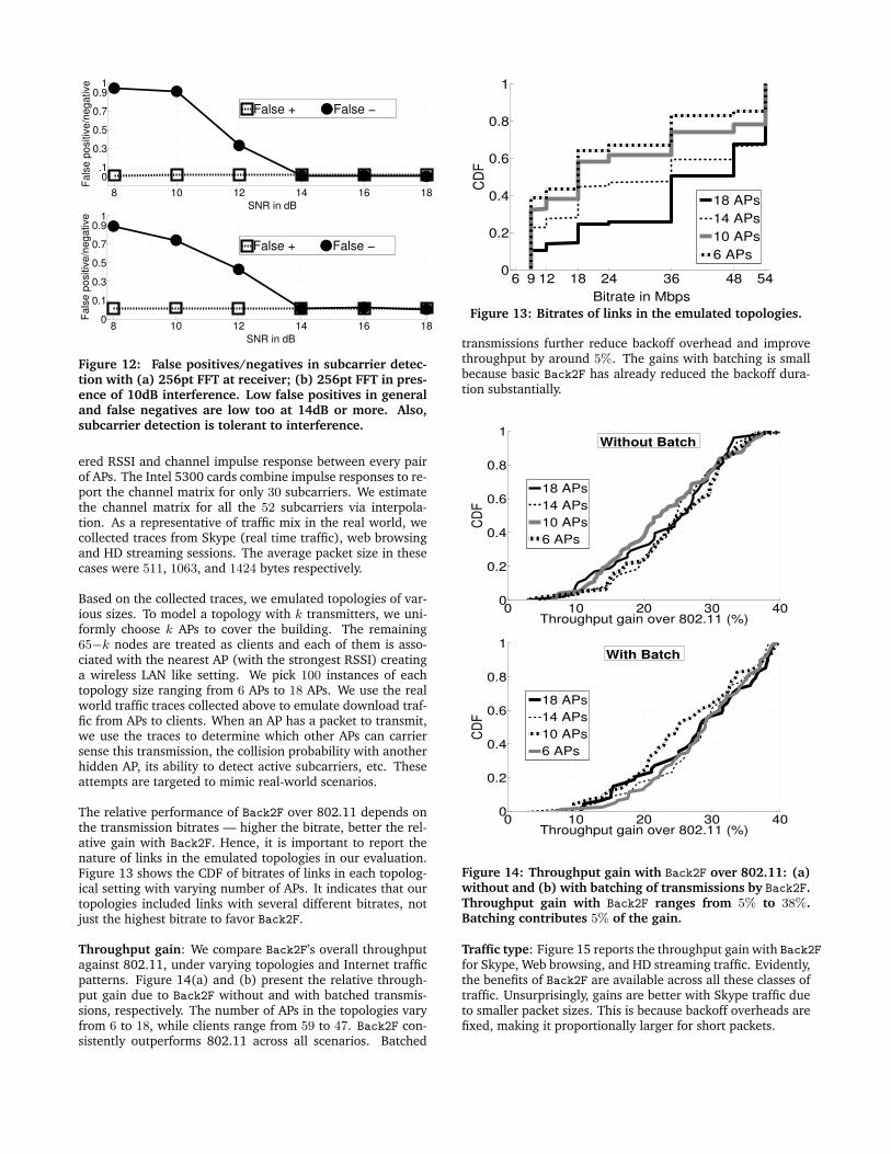
Figure 12: False positives/negatives in subcarrier detec-tion with (a) 256pt FFT at receiver; (b) 256pt FFT in pres-ence of 10dB interference. Low false positives in generaland false negatives are low too at 14dB or more. Also,subcarrier detection is tolerant to interference.
ered RSSI and channel impulse response between every pairof APs. The Intel 5300 cards combine impulse responses to re-port the channel matrix for only 30 subcarriers. We estimatethe channel matrix for all the 52 subcarriers via interpola-tion. As a representative of traffic mix in the real world, wecollected traces from Skype (real time traffic), web browsingand HD streaming sessions. The average packet size in thesecases were 511, 1063, and 1424 bytes respectively.
Based on the collected traces, we emulated topologies of var-ious sizes. To model a topology with k transmitters, we uni-formly choose k APs to cover the building. The remaining65−k nodes are treated as clients and each of them is asso-ciated with the nearest AP (with the strongest RSSI) creatinga wireless LAN like setting. We pick 100 instances of eachtopology size ranging from 6 APs to 18 APs. We use the realworld traffic traces collected above to emulate download traf-fic from APs to clients. When an AP has a packet to transmit,we use the traces to determine which other APs can carriersense this transmission, the collision probability with anotherhidden AP, its ability to detect active subcarriers, etc. Theseattempts are targeted to mimic real-world scenarios.
The relative performance of Back2F over 802.11 depends onthe transmission bitrates — higher the bitrate, better the rel-ative gain with Back2F. Hence, it is important to report thenature of links in the emulated topologies in our evaluation.Figure 13 shows the CDF of bitrates of links in each topolog-ical setting with varying number of APs. It indicates that ourtopologies included links with several different bitrates, notjust the highest bitrate to favor Back2F.
Throughput gain: We compare Back2F’s overall throughputagainst 802.11, under varying topologies and Internet trafficpatterns. Figure 14(a) and (b) present the relative through-put gain due to Back2F without and with batched transmis-sions, respectively. The number of APs in the topologies varyfrom 6 to 18, while clients range from 59 to 47. Back2F con-sistently outperforms 802.11 across all scenarios. Batched
6 9 12 18 24 36 48 540
0.2
0.4
0.6
0.8
1
Bitrate in Mbps
CD
F
18 APs
14 APs
10 APs
6 APs
Figure 13: Bitrates of links in the emulated topologies.
transmissions further reduce backoff overhead and improvethroughput by around 5%. The gains with batching is smallbecause basic Back2F has already reduced the backoff dura-tion substantially.
0 10 20 30 400
0.2
0.4
0.6
0.8
1
Throughput gain over 802.11 (%)
CD
F
18 APs
14 APs
10 APs
6 APs
Without Batch
0 10 20 30 400
0.2
0.4
0.6
0.8
1
Throughput gain over 802.11 (%)
CD
F
18 APs
14 APs
10 APs
6 APs
With Batch
Figure 14: Throughput gain with Back2F over 802.11: (a)without and (b) with batching of transmissions by Back2F.Throughput gain with Back2F ranges from 5% to 38%.Batching contributes 5% of the gain.
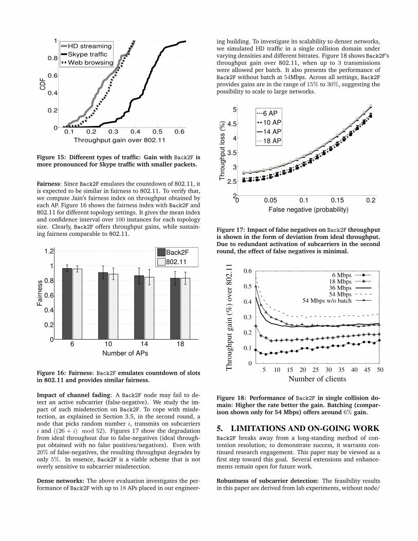
Traffic type: Figure 15 reports the throughput gain with Back2F
for Skype, Web browsing, and HD streaming traffic. Evidently,the benefits of Back2F are available across all these classes oftraffic. Unsurprisingly, gains are better with Skype traffic dueto smaller packet sizes. This is because backoff overheads arefixed, making it proportionally larger for short packets.
0.1 0.2 0.3 0.4 0.5 0.60
0.2
0.4
0.6
0.8
1
Throughput gain over 802.11
CD
F
HD streaming
Skype traffic
Web browsing
Figure 15: Different types of traffic: Gain with Back2F ismore pronounced for Skype traffic with smaller packets.
Fairness: Since Back2F emulates the countdown of 802.11, itis expected to be similar in fairness to 802.11. To verify that,we compute Jain’s fairness index on throughput obtained byeach AP. Figure 16 shows the fairness index with Back2F and802.11 for different topology settings. It gives the mean indexand confidence interval over 100 instances for each topologysize. Clearly, Back2F offers throughput gains, while sustain-ing fairness comparable to 802.11.
6 10 14 180
0.2
0.4
0.6
0.8
1
1.2
Number of APs
Fairness
Back2F
802.11
Figure 16: Fairness: Back2F emulates countdown of slotsin 802.11 and provides similar fairness.
Impact of channel fading: A Back2F node may fail to de-tect an active subcarrier (false-negative). We study the im-pact of such misdetection on Back2F. To cope with misde-tection, as explained in Section 3.5, in the second round, anode that picks random number i, transmits on subcarriersi and ((26 + i) mod 52). Figures 17 show the degradationfrom ideal throughout due to false-negatives (ideal through-put obtained with no false positives/negatives). Even with20% of false-negatives, the resulting throughput degrades byonly 5%. In essence, Back2F is a viable scheme that is notoverly sensitive to subcarrier misdetection.
Dense networks: The above evaluation investigates the per-formance of Back2F with up to 18 APs placed in our engineer-
ing building. To investigate its scalability to denser networks,we simulated HD traffic in a single collision domain undervarying densities and different bitrates. Figure 18 shows Back2F’sthroughput gain over 802.11, when up to 3 transmissionswere allowed per batch. It also presents the performance ofBack2F without batch at 54Mbps. Across all settings, Back2Fprovides gains are in the range of 15% to 30%, suggesting thepossibility to scale to large networks.
0 0.05 0.1 0.15 0.22
2.5
3
3.5
4
4.5
5
False negative (probability)
Thro
ughput lo
ss (
%)
6 AP
10 AP
14 AP
18 AP
Figure 17: Impact of false negatives on Back2F throughputis shown in the form of deviation from ideal throughput.Due to redundant activation of subcarriers in the secondround, the effect of false negatives is minimal.
0
0.1
0.2
0.3
0.4
0.5
0.6
5 10 15 20 25 30 35 40 45 50Th
rou
gh
pu
t g
ain
(%
) o
ver
80
2.1
1
Number of clients
6 Mbps18 Mbps36 Mbps54 Mbps
54 Mbps w/o batch
Figure 18: Performance of Back2F in single collision do-main: Higher the rate better the gain. Batching (compar-ison shown only for 54 Mbps) offers around 6% gain.
5. LIMITATIONS AND ON-GOING WORKBack2F breaks away from a long-standing method of con-tention resolution; to demonstrate success, it warrants con-tinued research engagement. This paper may be viewed as afirst step toward this goal. Several extensions and enhance-ments remain open for future work.
Robustness of subcarrier detection: The feasibility resultsin this paper are derived from lab experiments, without node/
environment mobility. Compared to time-domain backoff, Back2Fmay be more sensitive to channel fluctuations. As discussedearlier, subcarrier detection can be made more robust by strip-ing signals over multiple subcarriers, in order to convey abackoff value. We need to investigate such techniques fur-ther and carefully evaluate subcarrier detection under harshconditions.
Collisions due to hidden terminals: Contention resolutionschemes are not designed to cope with hidden terminal prob-lems. However, when using 802.11, the exponential increasein backoff may eventually separate the hidden terminals intime, permitting a successful transmission. Of course, once asuccess occurs, 802.11 resets its contention window, bringingback the hidden terminal problem. With Back2F, the hiddenterminals would continue to collide if they continue to trans-mit, and in that sense, 802.11 might be slightly better. Nev-ertheless, we observe that Back2F collisions are solely due tohidden terminals; collisions caused by identical backoff valuesare far less likely in Back2F. Thus, Back2F can confidently di-agnose the cause of collisions, and perhaps turn on RTS/CTSin the face of collisions. 802.11, on the other hand, would stillneed to discriminate between the cases of identical-backoffand hidden terminals.
Need for an additional antenna: Back2F has to transmitand listen simultaneously only during backoff. The listeningantenna can very well act as an additional antenna duringnormal transmission/reception, such as in a MIMO system.In other words, Back2F is complementary to MIMO. In fact,the feasibility of higher data rates with MIMO emphasizes theneed to eliminate idle slots, and thereby adopt Back2F-likeschemes. Even without MIMO, given that there are other usesof an additional antenna [25], its inclusion in WiFi devicesmay very well be worthwhile.
Gain over packet aggregation: 802.11n uses packet aggre-gation to reduce the contention overhead. The natural ques-tion then is whether Back2F is still beneficial. Depending onthe type of traffic (e.g., VoIP), aggregation may not be possi-ble nor suitable [27, 29, 30]. Even with packet aggregation,Back2F provides gains at high bitrates. Besides, Back2F ad-dresses a fundamental problem of resolving contention keep-ing the channel utilization high, regardless of the traffic pat-tern.
Interoperability with 802.11: We believe Back2F can inter-operate with (legacy) 802.11 nodes but may cause unfairnessto them. A potential approach to alleviate unfairness is tohave Back2F wait for longer than DIFS before participating ina backoff. This gives legacy nodes opportunity to countdownand eventually transmit. We need to understand this interac-tion, and study the feasibility of incremental deployment ofBack2F.
Analysis and Correctness: Back2F emulates the countdownof 802.11 and therefore we believe it is similar to 802.11in correctness and fairness. We have simulated Back2F formore than 48 hours on various network topologies – we havenot encountered deadlocks, starvations, or other correctnessproblems. However, we have not formally analyzed Back2F’scorrectness properties. We leave an analytical treatment ofBack2F to future work.
6. RELATED WORKThe notion of backoff dates back to 1973, when pure/slottedALOHA systems [4] were introduced (see [14] for a historyon spectrum sharing). The core ideas from ALOHANet havefound wide applicability in Ethernet, the Inmarsat satellitenetwork, and most recently, in WiFi [3,5]. With WiFi’s popu-larity, exponential backoff became a heavily researched topic.Discussing this entire literature is difficult – we only discussrepresentative ideas, and discriminate them from Back2F.
Regulating Increase/Decrease: One thread of proposals haveoptimized the manner in which backoff adapts to collisionsand network conditions. MACAW [5] proposes doubling ofthe backoff upon packet loss, but decrease of 1 upon success.PFCR proposed similar policies, but from the fairness perspec-tive [19]. While these and other schemes [20] were appeal-ing for their simplicity, practical measurements [15, 16] andanalytical studies [6] show that the inherent inefficiencies re-main, and become pronounced in unfavorable conditions.
Contention Estimation: In another research thread, researchersattempted to adapt the backoff scheme based on estimationsof network traffic/contention [12]. Unfortunately, such esti-mations are not always reliable due to unpredictable varia-tions in traffic patterns [7].
Scheduling (Centralized and Distributed): TCF [17] elimi-nates contention overhead by allocating the channel dynami-cally using a TDMA-style scheme. Noting the difficulties withsynchronization and prediction in TDMA, ZMAC [22] pro-posed a hybrid MAC allowing CSMA for low contention en-vironments and TDMA for high contention regimes. Whilecreative, performance degradation in low contention regimes,as well as heavy coordination overhead, makes ZMAC imprac-tical for dense networks. Several centralized solutions lever-age a central controller to schedule transmissions in single-administrator environments, like offices, airports, etc. [18,28]. Unfortunately, they do not scale to chaotic networks,such as in residential WLANs or for MiFi networks among per-sonal devices.
PHY based Techniques: Recently, PHY capabilities are be-ing leveraged to redesign higher layer protocols [10, 11, 21,25, 29]. FICA [29] showed the possibility of signaling onthe frequency domain to facilitate fine grained FDMA. Whilesome ideas bear resemblance to Back2F, FICA requires in-volved RTS/CTS exchanges and a common “referee” node toperform the arbitration, similar to ideas in [23]. Also, theapproach in [23] relies on tight time synchronization, thatmay experience practical challenges in a real system. Theprotocol in [24] performs frequency domain backoff, how-ever, it does not address multiple collision domains, fairness,starvation, fading, etc. Evaluation is also limited. Back2F
demonstrates the feasibility of a distributed backoff mecha-nism, free of RTS/CTS and referee nodes. The use of an ad-ditional antenna, a second round of contention, resilience tofading, packet batching, and a functional prototype, discrimi-nate Back2F from existing work. We believe that Back2F is adeparture from established ideas in time-domain contentionresolution, begging the question: what else can be migrated tothe frequency domain?
7. CONCLUSIONRandomization is an effective method of contention resolu-tion in systems with shared resources. Several protocols im-plement contention resolution by requiring nodes to wait forrandom durations. During this wait, the channel must re-main idle, forcing undesirable under-utilization of channel.This paper proposes a nearly-instantaneous contention res-olution method by exploiting the opportunity to operate onthe frequency domain (using OFDM subcarriers). A proof-of-concept on a small USRP testbed confirms feasibility andpromising performance improvement. Developing a full-scaledesign is the natural next step.
8. ACKNOWLEDGEMENTWe sincerely thank the anonymous reviewers for their valu-able feedback on this paper. We are also grateful to NSF forpartially funding this research through the following grants –CNS-0448272, CNS-0917020, CNS-0916995, and CNS-0747206.
9. REFERENCES[1] IEEE 802.11-2007 standard. standards.ieee.org/
getieee802/download/802.11-2007.pdf .[2] Intel802.11n channel measurement tool. ils.intel-
research.net/80211n-channel-measurement-tool.[3] 802.11: Wireless LAN medium access control (MAC)
and physical layer (PHY) specifications, 1997.[4] ABRAMSON, N. The Aloha System: another alternative
for computer communications. In Proceedings of the Falljoint computer conference (1970), ACM.
[5] BHARGHAVAN, V., DEMERS, A. J., SHENKER, S., , ANDZHANG, L. MACAW: A media access protocol forwireless lan’s. In SIGCOMM (1994).
[6] BIANCHI, G. Performance analysis of the IEEE 802.11distributed coordination function. IEEE Journal onselected areas in communications 18, 3 (2000),535–547.
[7] BIANCHI, G., AND TINNIRELLO, I. Kalman filterestimation of the number of competing terminals in anIEEE 802.11 network. In INFOCOM (2003).
[8] BRODSKY, M., AND MORRIS, R. In defense of wirelesscarrier sense. In ACM SIGCOMM (2009).
[9] CHOI, J., JAIN, M., SRINIVASAN, K., LEVIS, P., ANDKATTI, S. Achieving single channel, full duplex wirelesscommunication. ACM MOBICOM (2010).
[10] DUTTA, A., SAHA, D., GRUNWALD, D., AND SICKER, D.SMACK: a SMart ACKnowledgment scheme forbroadcast messages in wireless networks. ACMSIGCOMM (2009).
[11] GOLLAKOTA, S., AND KATABI, D. Zigzag decoding:Combating hidden terminals in wireless networks. ACMSIGCOMM (2008).
[12] HAAS, Z., AND DENG, J. On optimizing the backoffinterval for random access schemes. Communications,IEEE Transactions on 51, 12 (2004), 2081–2090.
[13] HE, Y., YUAN, R., SUN, J., AND GONG, W.Semi-Random Backoff: Towards resource reservationfor channel access in wireless LANs. IEEE ICNP (2009).
[14] JACKSON, C. Dynamic sharing of radio spectrum: Abrief history. In IEEE DySPAN (2005).
[15] JARDOSH, A., MITTAL, K., RAMACHANDRAN, K.,BELDING, E., AND ALMEROTH, K. IQU: practicalqueue-based user association management for WLANs.In MOBICOM (2006).
[16] JARDOSH, A., RAMACHANDRAN, K., ALMEROTH, K.,AND BELDING-ROYER, E. Understanding congestion inIEEE 802.11 b wireless networks. In ACM IMC (2005).
[17] LIM, C., AND CHOI, C. TDM-based coordinationfunction (TCF) in WLAN for high throughput. InGLOBECOM (2005).
[18] MANWEILER, J., SANTHAPURI, N., SEN, S.,ROY CHOUDHURY, R., NELAKUDITI, S., ANDMUNAGALA, K. Order matters: transmission reorderingin wireless networks. In Proceedings of the 15th annualinternational conference on Mobile computing andnetworking (2009), ACM, pp. 61–72.
[19] NANDAGOPAL, T., KIM, T., GAO, X., AND BHARGHAVAN,V. Achieving MAC layer fairness in wireless packetnetworks. In ACM MOBICOM (2000), pp. 87–98.
[20] PANG, Q., LIEW, S., LEE, J., AND LEUNG, V.Performance evaluation of an adaptive backoff schemefor WLAN. Wireless Communications and MobileComputing 4, 8 (2004), 867–879.
[21] RAHUL, H., EDALAT, F., KATABI, D., AND SODINI, C.Frequency-aware rate adaptation and MAC protocols.In MOBICOM (2009).
[22] RHEE, I., WARRIER, A., AIA, M., AND MIN, J. ZMAC: AHybrid MAC for Wireless Sensor Networks. ACM SenSys(2005).
[23] ROMAN, B., STAJANO, F., WASSELL, I., ANDCOTTINGHAM, D. Multi-carrier burst contention(MCBC): Scalable medium access control for wirelessnetworks. In IEEE WCNC (2008).
[24] SEN, S., CHOUDHURY, R., AND NELAKUDITI, S. Listen(on the Frequency Domain) Before You Talk. ACMHOTNETS (2010).
[25] SEN, S., ROY CHOUDHURY, R., AND NELAKUDITI, S.CSMA/CN: Carrier Sense Multiple Access withCollision Notification. ACM MOBICOM (2010).
[26] SEN, S., SANTHAPURI, N., CHOUDHURY, R., ANDNELAKUDITI, S. AccuRate: Constellation Based RateEstimation in Wireless Networks. In NSDI (2010).
[27] SHIN, S., AND SCHULZRINNE, H. Experimentalmeasurement of the capacity for voip traffic in ieee802.11 wlans. In INFOCOM (2007), IEEE.
[28] SHRIVASTAVA, V., AHMED, N., RAYANCHU, S.,BANERJEE, S., KESHAV, S., PAPAGIANNAKI, K., ANDMISHRA, A. Centaur: Realizing the full potential ofcentralized wlans through a hybrid data path. InMOBICOM (2009).
[29] TAN, K., FANG, J., ZHANG, Y., CHEN, S., SHI, L.,ZHANG, J., AND ZHANG, Y. Fine Grained ChannelAccess in Wireless LAN. ACM SIGCOMM (2010).
[30] VERKAIK, P., AGARWAL, Y., GUPTA, R., AND SNOEREN,A. Softspeak: making VoIP play well in existing 802.11deployments. In NSDI (2009).
[31] VUTUKURU, M., BALAKRISHNAN, H., AND JAMIESON, K.Cross-layer wireless bit rate adaptation. ACMSIGCOMM (2009).