
No Slide Titlecas.web.cern.ch/sites/cas.web.cern.ch/files/lectures/...Business Tier (Web Container)...
55
Accelerator Controls CAS 2005 Hermann Schmickler
Transcript of No Slide Titlecas.web.cern.ch/sites/cas.web.cern.ch/files/lectures/...Business Tier (Web Container)...
Accelerator Controls
CAS 2005
Hermann Schmickler
Accelerator ControlsCAS 2005 Hermann Schmickler (CERN - AB)
Outline
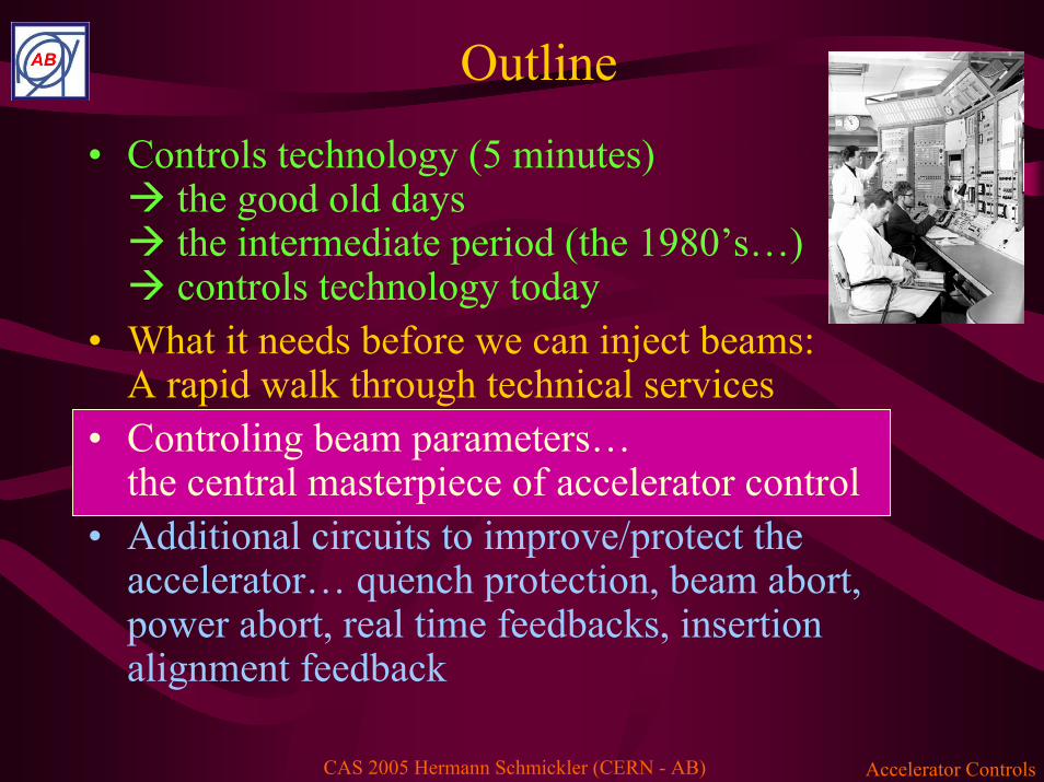
• Controls technology (5 minutes)the good old daysthe intermediate period (the 1980’s…)controls technology today
• What it needs before we can inject beams:A rapid walk through technical services
• Controling beam parameters…the central masterpiece of accelerator control
• Additional circuits to improve/protect theaccelerator… quench protection, beam abort, power abort, real time feedbacks, insertion alignment feedback

Accelerator ControlsCAS 2005 Hermann Schmickler (CERN - AB)
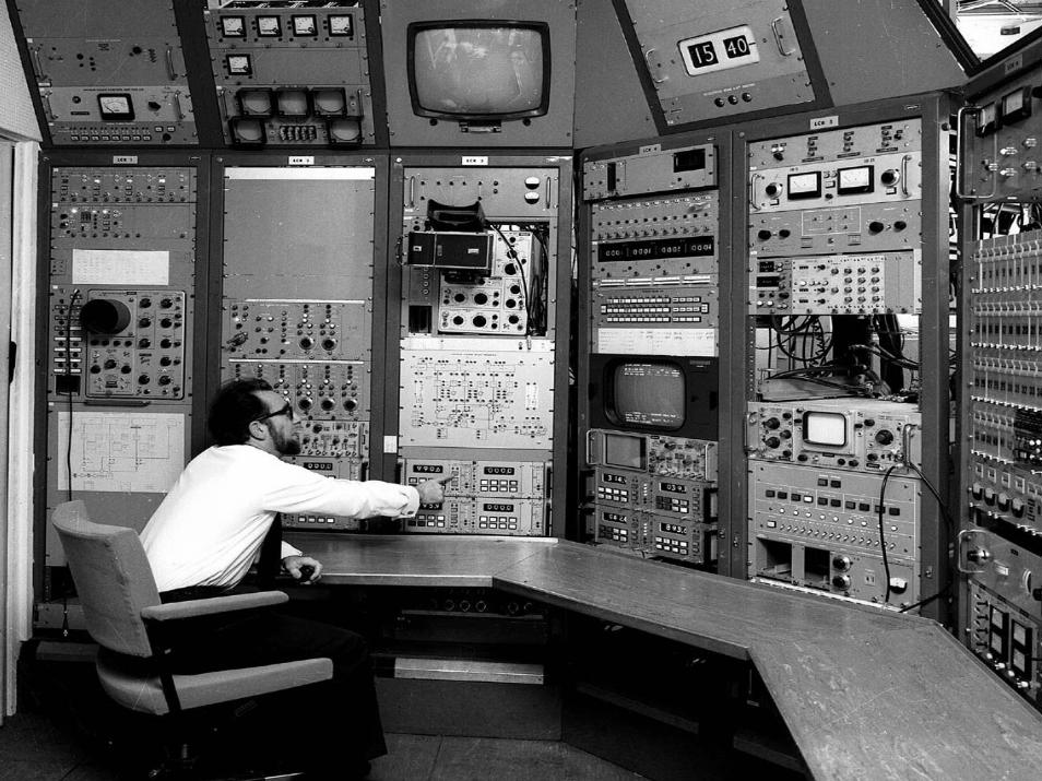
Controls technology• …did barely exist in the
« good old days ».Machines were small in size and all equipmentcontrol was routed via cables into a central control room.
• Switches, potentiometersand indicators (lampes, meters) were physicallyinstalled in the control room.
• Beam Diagnstics wasdone with instruments locally in the control room.
Accelerator ControlsCAS 2005 Hermann Schmickler (CERN - AB)

Accelerator ControlsCAS 2005 Hermann Schmickler (CERN - AB)
The intermediate period…• Onset of computer control…• No widely accepted industry standards existed for front-end
computers and for console computers; low educational level oftechnical staff on computer technology
• Complete lack of standards for real time operating systems andsystems intercommunication.
• Networking only in its beginning• Performance limits of computers were significant.
Still many systems ( beam instrumentation and RF) with direct high frequency cables to control room.
• In terms of controls: a total mess
Accelerator ControlsCAS 2005 Hermann Schmickler (CERN - AB)
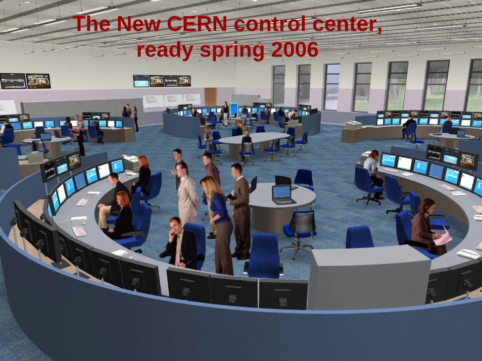
The New CERN control center,ready spring 2006
Accelerator ControlsCAS 2005 Hermann Schmickler (CERN - AB)
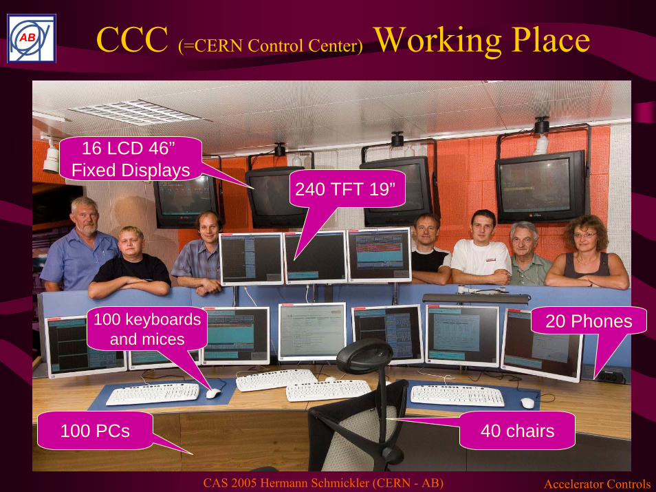
CCC (=CERN Control Center) Working Place
240 TFT 19”
16 LCD 46”Fixed Displays
100 PCs 40 chairs
100 keyboardsand mices
20 Phones
Accelerator ControlsCAS 2005 Hermann Schmickler (CERN - AB)
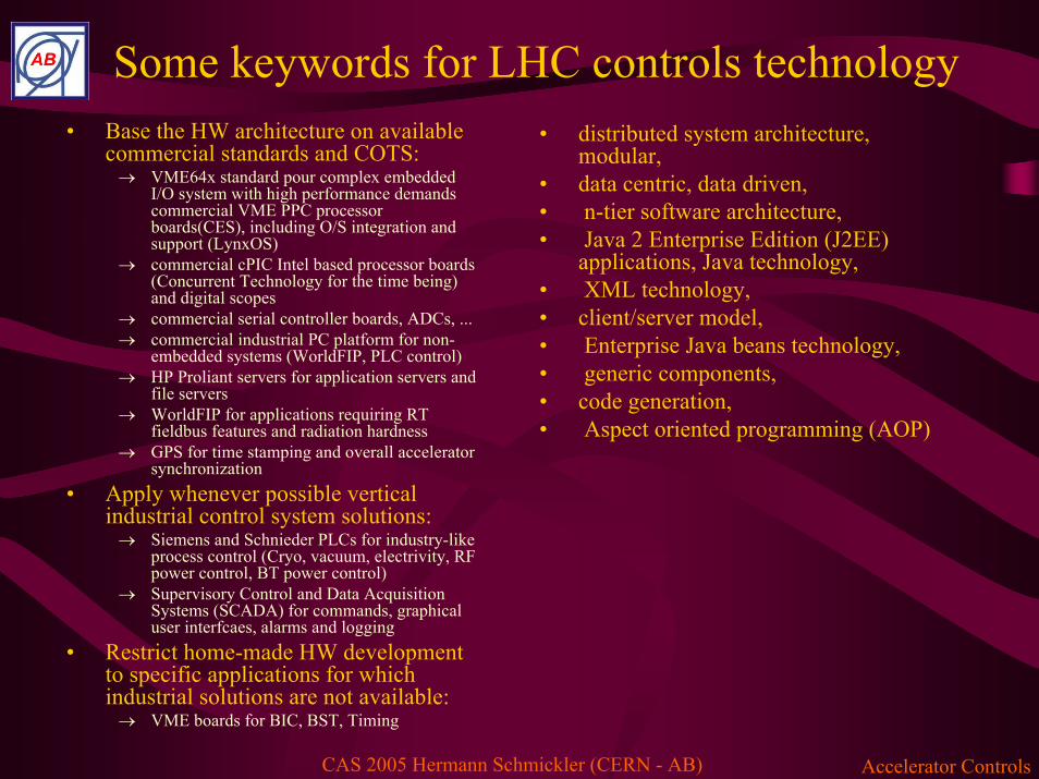
Some keywords for LHC controls technology• Base the HW architecture on available
commercial standards and COTS:→ VME64x standard pour complex embedded
I/O system with high performance demands commercial VME PPC processor boards(CES), including O/S integration and support (LynxOS)
→ commercial cPIC Intel based processor boards (Concurrent Technology for the time being) and digital scopes
→ commercial serial controller boards, ADCs, ... → commercial industrial PC platform for non-
embedded systems (WorldFIP, PLC control) → HP Proliant servers for application servers and
file servers → WorldFIP for applications requiring RT
fieldbus features and radiation hardness → GPS for time stamping and overall accelerator
synchronization• Apply whenever possible vertical
industrial control system solutions:→ Siemens and Schnieder PLCs for industry-like
process control (Cryo, vacuum, electrivity, RF power control, BT power control)
→ Supervisory Control and Data Acquisition Systems (SCADA) for commands, graphical user interfcaes, alarms and logging
• Restrict home-made HW development to specific applications for which industrial solutions are not available:→ VME boards for BIC, BST, Timing
• distributed system architecture, modular,
• data centric, data driven,• n-tier software architecture,• Java 2 Enterprise Edition (J2EE)
applications, Java technology,• XML technology, • client/server model,• Enterprise Java beans technology,• generic components, • code generation,• Aspect oriented programming (AOP)

Accelerator ControlsCAS 2005 Hermann Schmickler (CERN - AB)
LHC control system Architecture
Datastore
Devices
accsoft-settings
macsy-generation
macsy-trim
macsy-sequence
macsy-exploitation
accsoft-optics
JAPCcmw-rda
JAPCcmwrdaJAPC
HibernateDAO
JAPC
JAPCremoteclient
macsyclient
Remote
HTTP
Layer
)
macsyclientimpl
Business Tier (Web Container)
Appli-cations
Client Tier
JAPC remote server
Parameters concentration

Accelerator ControlsCAS 2005 Hermann Schmickler (CERN - AB)
…and an uncountable number of application programs
Accelerator ControlsCAS 2005 Hermann Schmickler (CERN - AB)
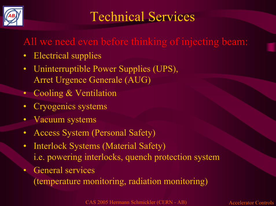
Technical Services
All we need even before thinking of injecting beam:• Electrical supplies • Uninterruptible Power Supplies (UPS),
Arret Urgence Generale (AUG)• Cooling & Ventilation• Cryogenics systems• Vacuum systems• Access System (Personal Safety)• Interlock Systems (Material Safety)
i.e. powering interlocks, quench protection system• General services
(temperature monitoring, radiation monitoring)

Accelerator ControlsCAS 2005 Hermann Schmickler (CERN - AB)
The “look and feel” of all these systemsexample: vacuum system for LHC transfer line
AT-VAC/IN Section
Synoptic of the SPS Complex
Pressure profile in LHC TI8
Vacuum sectorisation of LHC TI8Vacuum layout of
LHC TI8
I.Laugier AT-VAC

Accelerator ControlsCAS 2005 Hermann Schmickler (CERN - AB)
A typical implementationQuantum
PremiumEthernet
Telefast
Digital
Phoenix
Analog
PMAModbus
DPPA
PA
PA
PLCSafety
BUS X
AT-ACR
GatewayWFIP
GatewaySiemens
ET 200Boards
WFIP Networks
WFIP agents
CentralData server
Central & local control room
Operator consoles
Various front end interfaces

Accelerator ControlsCAS 2005 Hermann Schmickler (CERN - AB)
Finally: Beam Control→Transfer lines→Injection and Extraction (beam dumping system)→Beam optics controls
i.e. all power converters→Beam instrumentation →RF→Beam interlocks→Collimation→Real Time feedbacks→Machine Protection→Timing Systems→Radiation monitors
759.98
760.00
760.02
760.04
760.06
0 1 2 3 4Seconds
Amps
ImeasIref
Static and dynamic control, We will discuss in detail the setting at
injection and the ramping of the main dipole power converter
2 ppm = 14 MeVof full current
Accelerator ControlsCAS 2005 Hermann Schmickler (CERN - AB)
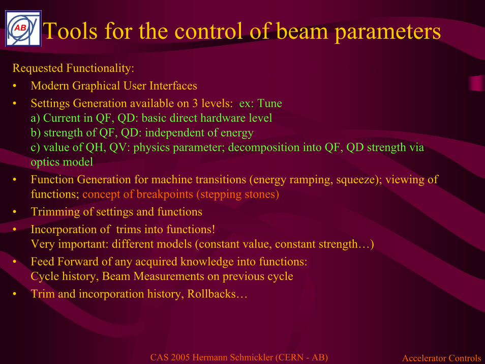
Requested Functionality:• Modern Graphical User Interfaces• Settings Generation available on 3 levels: ex: Tune
a) Current in QF, QD: basic direct hardware levelb) strength of QF, QD: independent of energyc) value of QH, QV: physics parameter; decomposition into QF, QD strength via optics model
• Function Generation for machine transitions (energy ramping, squeeze); viewing of functions; concept of breakpoints (stepping stones)
• Trimming of settings and functions• Incorporation of trims into functions!
Very important: different models (constant value, constant strength…)• Feed Forward of any acquired knowledge into functions:
Cycle history, Beam Measurements on previous cycle• Trim and incorporation history, Rollbacks…
Tools for the control of beam parameters

Accelerator ControlsCAS 2005 Hermann Schmickler (CERN - AB)
Generic Equipment Control
Accelerator ControlsCAS 2005 Hermann Schmickler (CERN - AB)
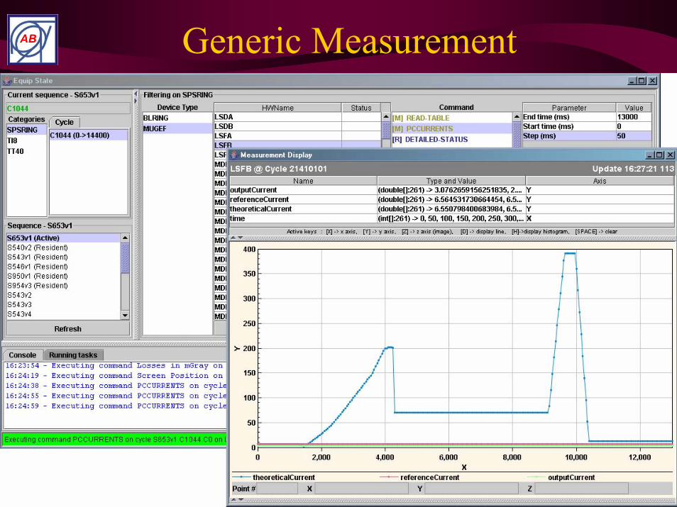
Generic Measurement
Accelerator ControlsCAS 2005 Hermann Schmickler (CERN - AB)
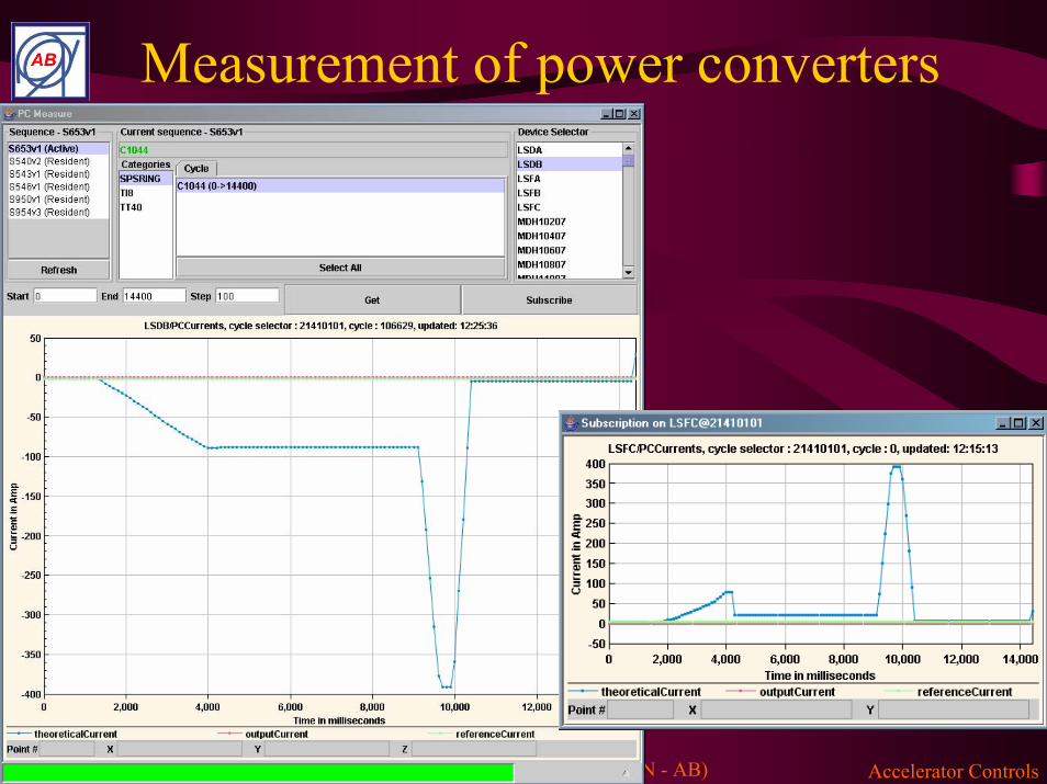
Measurement of power converters
Accelerator ControlsCAS 2005 Hermann Schmickler (CERN - AB)
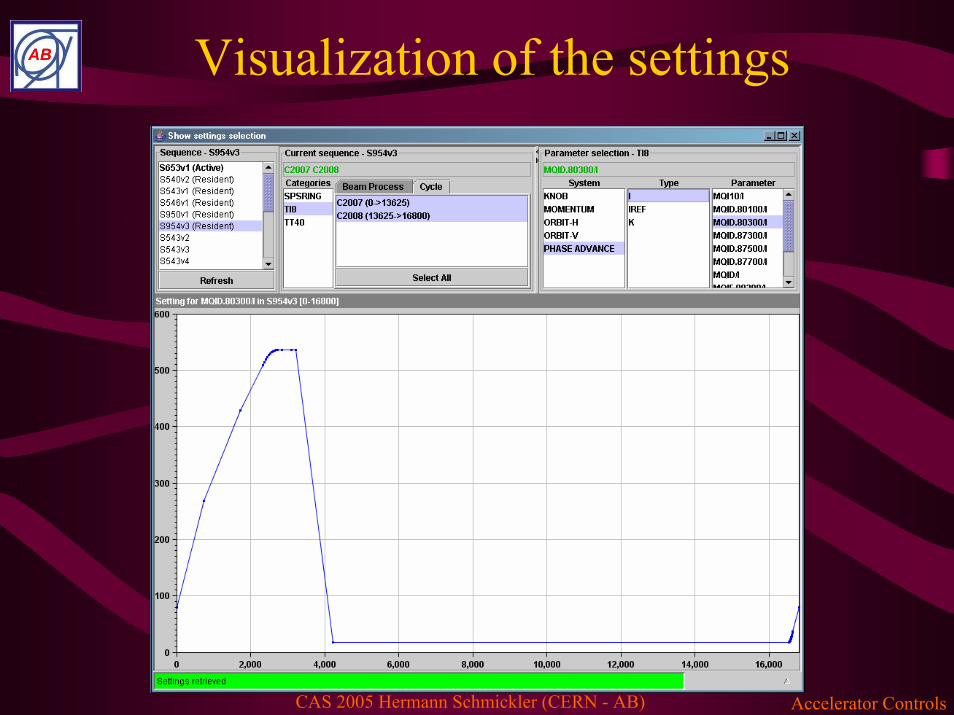
Visualization of the settings
Accelerator ControlsCAS 2005 Hermann Schmickler (CERN - AB)
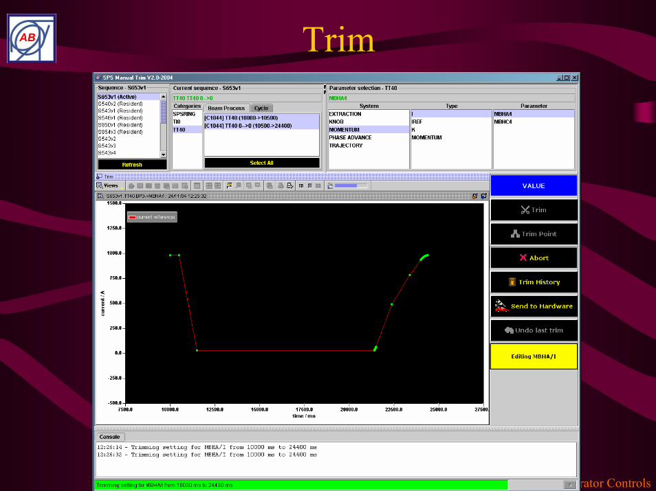
Trim
Accelerator ControlsCAS 2005 Hermann Schmickler (CERN - AB)
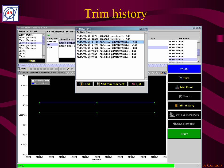
Trim history

Accelerator ControlsCAS 2005 Hermann Schmickler (CERN - AB)
Supporting Tools for Operation
• Beam Measurement – Inspection – Correction – Trimex: Orbit Correction…The whole suite of beam diagnostics
• Sequencing• Online Machine Models• Archiving of measurements• Automatic logging and data retrieval (correlation studies)• Post Mortem Analysis Tools• Fixed Displays (the 16 big screens in the CCC…)• ELogBook• Statistics
Accelerator ControlsCAS 2005 Hermann Schmickler (CERN - AB)
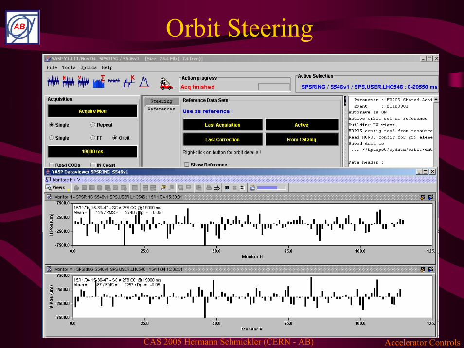
Orbit Steering
Accelerator ControlsCAS 2005 Hermann Schmickler (CERN - AB)
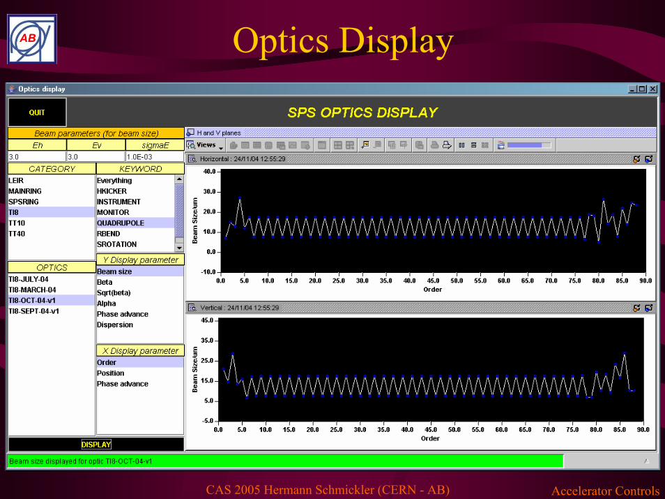
Optics Display

Accelerator ControlsCAS 2005 Hermann Schmickler (CERN - AB)
Logging & Monitoring

Accelerator ControlsCAS 2005 Hermann Schmickler (CERN - AB)
Statistics
Data hauled from database automatically at end of fill

Accelerator ControlsCAS 2005 Hermann Schmickler (CERN - AB)
Retrieval of archived measurements

Accelerator ControlsCAS 2005 Hermann Schmickler (CERN - AB)
Browser & Viewer
Accelerator ControlsCAS 2005 Hermann Schmickler (CERN - AB)L
uminosity
0
0.02
0.04
0.06
0.08
0 0.2 0.4 0.6 0.8
Bunch current (mA)
Ver
tical
bea
m-b
eam
tune
shi
ft ξ
y
2 4 6 8 10 x 1031 m-2 s-1
κ =
1 %
, ε y =
0.2
3 nm
κ = 2 %
, ε y = 0.46 nm
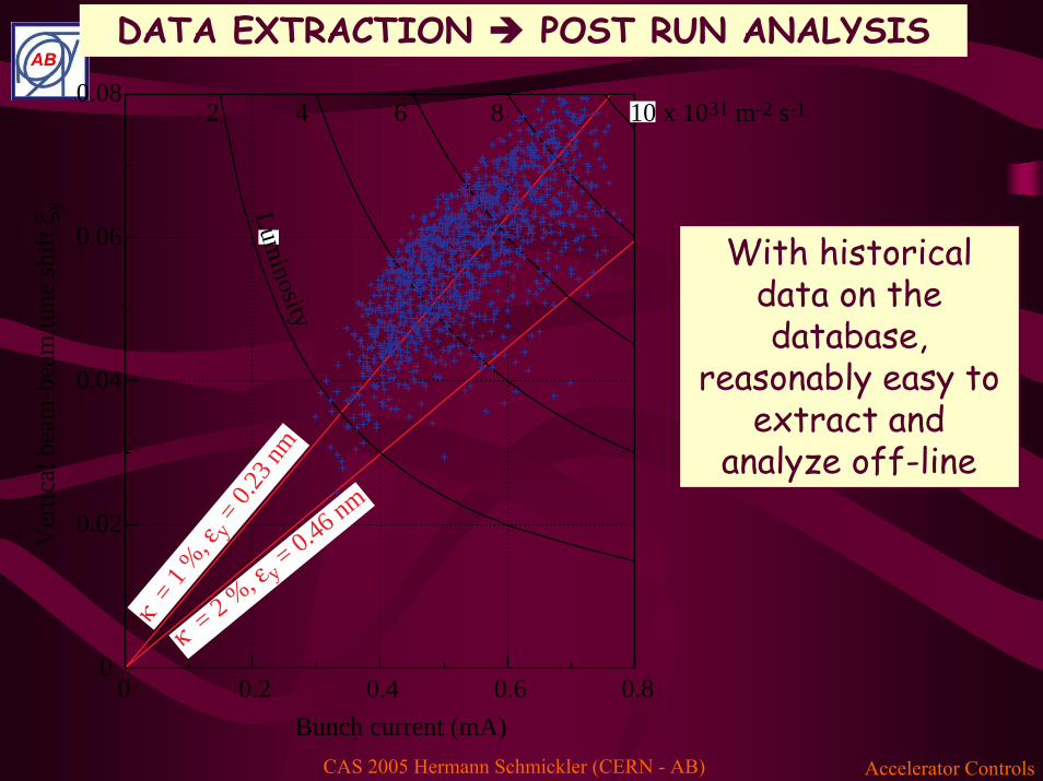
With historical data on the database,
reasonably easy to extract and
analyze off-line
DATA EXTRACTION POST RUN ANALYSIS
Accelerator ControlsCAS 2005 Hermann Schmickler (CERN - AB)
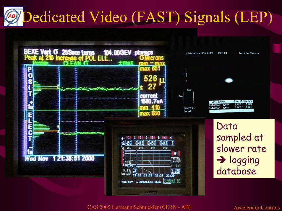
Dedicated Video (FAST) Signals (LEP)
Data sampled at slower rate
logging database
Accelerator ControlsCAS 2005 Hermann Schmickler (CERN - AB)
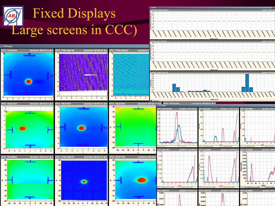
Fixed DisplaysLarge screens in CCC)

Accelerator ControlsCAS 2005 Hermann Schmickler (CERN - AB)
Now we take a closer look:Ex: Settings generation for the main bend MB- warm magnets:
1) injection setting from requested beam momentum setting and calibration curve of Magnet2) Magnetic history of dipoles handled via specific hysteresis cycles before injection (called: degaussing…)3) Online Feedback to actual setting via reference magnet4) Requested beam momentum refined by measuring extraction energy of preinjector5) Magnetic Model (or calibration curve) refined by momentum measurement in receiving machine6) Other cycle history handled as trim and rollback utility (i.e. “cold machine after shutdown”, “warm machine after 1 day of permanent operation”- cold magnets:things are more complicated…next slides

Accelerator ControlsCAS 2005 Hermann Schmickler (CERN - AB)
Available data for LHC magnets• warm measurements on the
production:→ all (superconducting) MB, MQ,
MQM, MQY: • main field integral strength • higher order geometric
harmonics→ all (superconducting) MBX,
MBRx, MQXx→ warm measurement on MQTL
so far at CERN→ most (superconducting) lattice
corrector and spool pieces (about 90% of data available)
→ all (warm) MQW→ a sample (5 to 10) of other warm
insertion magnets (MBXW, …measured at the manufacturer before delivery)
• at the present rate,cold measurements on:→ ≈ 20 % of MB and ≈ 20 % of MQ
in standard conditions→ special tests (injection decay and
snap-back, effect of long storage) on 15…20 MB
→ a sample of MQM and MQY → ≈ 75 % of MBX, MBRx→ 100 % of MQXx (Q1, Q2, Q3)→ a limited sample of lattice
correctors and spool pieces
Accelerator ControlsCAS 2005 Hermann Schmickler (CERN - AB)
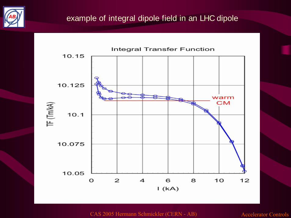
example of integral dipole field in an LHC dipole
Accelerator ControlsCAS 2005 Hermann Schmickler (CERN - AB)
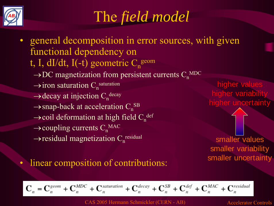
The field model• general decomposition in error sources, with given
functional dependency on t, I, dI/dt, I(-t) geometric Cn
geom
→DC magnetization from persistent currents CnMDC
→ iron saturation Cnsaturation
→decay at injection Cndecay
→snap-back at acceleration CnSB
→coil deformation at high field Cndef
→coupling currents CnMAC
→residual magnetization Cnresidual
• linear composition of contributions:
smaller valuessmaller variability
smaller uncertainty
higher valueshigher variability
higher uncertainty
Accelerator ControlsCAS 2005 Hermann Schmickler (CERN - AB)
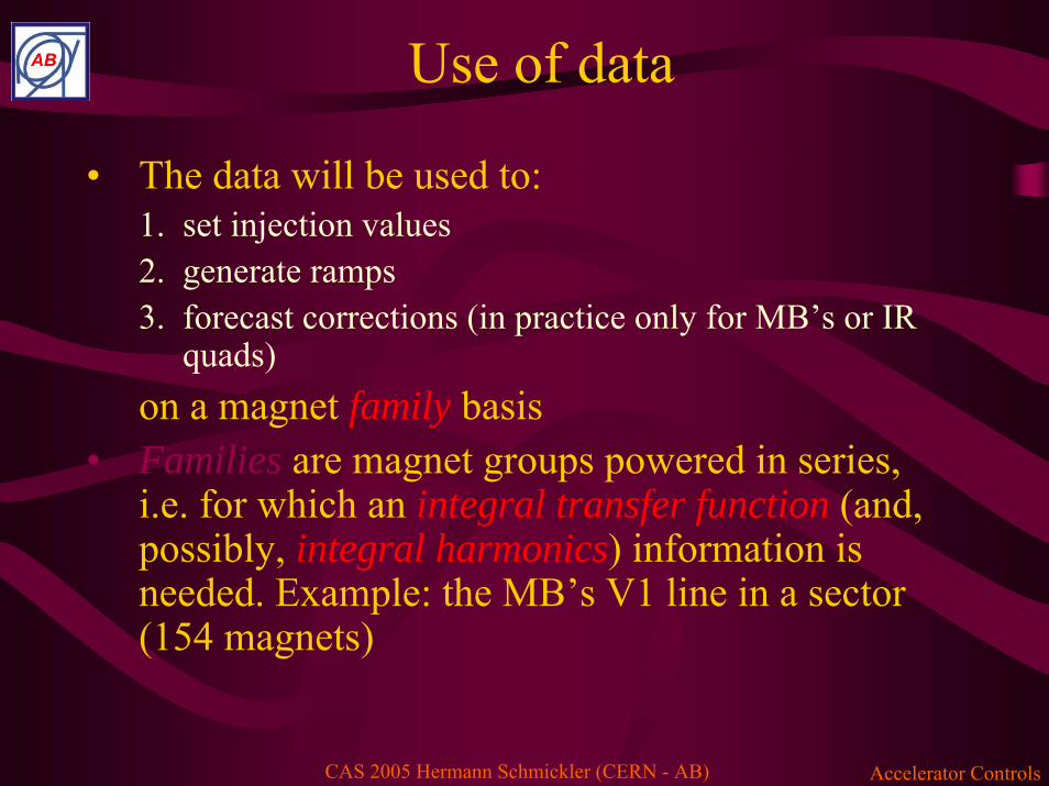
Use of data
• The data will be used to:1. set injection values2. generate ramps3. forecast corrections (in practice only for MB’s or IR
quads)on a magnet family basis
• Families are magnet groups powered in series, i.e. for which an integral transfer function (and, possibly, integral harmonics) information is needed. Example: the MB’s V1 line in a sector (154 magnets)
Accelerator ControlsCAS 2005 Hermann Schmickler (CERN - AB)
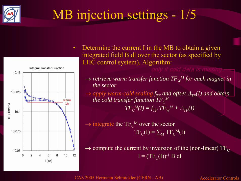
MB injection settings - 1/5
• Determine the current I in the MB to obtain a given integrated field B dl over the sector (as specified by LHC control system). Algorithm:
→ retrieve warm transfer function TFWM for each magnet in
the sector→ apply warm-cold scaling fTF and offset ΔTF(I) and obtain
the cold transfer function TFCM
TFCM(I) = fTF TFW
M + ΔTF(I)
→ integrate the TFCM over the sectorTFC(I) = ∑M TFC
M(I)
→ compute the current by inversion of the (non-linear) TFCI = (TFC(I))-1 B dl
only if cold data is missing
Accelerator ControlsCAS 2005 Hermann Schmickler (CERN - AB)
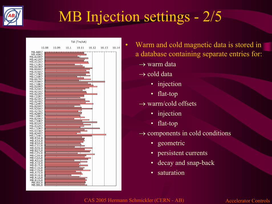
MB Injection settings - 2/5
• Warm and cold magnetic data is stored in a database containing separate entries for:→ warm data→ cold data
• injection• flat-top
→ warm/cold offsets• injection• flat-top
→ components in cold conditions• geometric• persistent currents• decay and snap-back• saturation
Accelerator ControlsCAS 2005 Hermann Schmickler (CERN - AB)
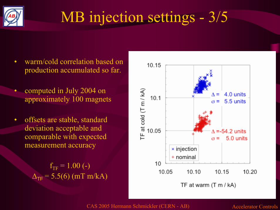
MB injection settings - 3/5
• warm/cold correlation based on production accumulated so far.
• computed in July 2004 on approximately 100 magnets
• offsets are stable, standard deviation acceptable and comparable with expected measurement accuracy
fTF = 1.00 (-)ΔTF = 5.5(6) (mT m/kA)

Accelerator ControlsCAS 2005 Hermann Schmickler (CERN - AB)
MB injection settings - 4/5
• The magnet installation sequence is determined at the Magnet Evaluation Board (MEB), based on constraints on:→ geometry→ field quality→ other (quench, non-conformities, …)
• The information is collected in an installation map, recorded in the Manufacturing and Test Folder (MTF)
We know which magnet is wherewe can build integral field information

Accelerator ControlsCAS 2005 Hermann Schmickler (CERN - AB)
MB injection settings - 5/5
• average transfer function at injection for sector 78 (extrapolated from 109/154 magnets allocated)
• warm/cold extrapolation for 44/109 magnets (65 cold measured)
TF1 = 10.117(5) (T m/kA)TF2 = 10.117(1) (T m/kA)
• current in sector 78 for an injection at 450 GeV from SPS(1189.2 T m)
I = 763.2(5) A= this corresponds to step 1 in the discussed sequence
The Control system receives and stores this setting and makes it available for trimming
Accelerator ControlsCAS 2005 Hermann Schmickler (CERN - AB)
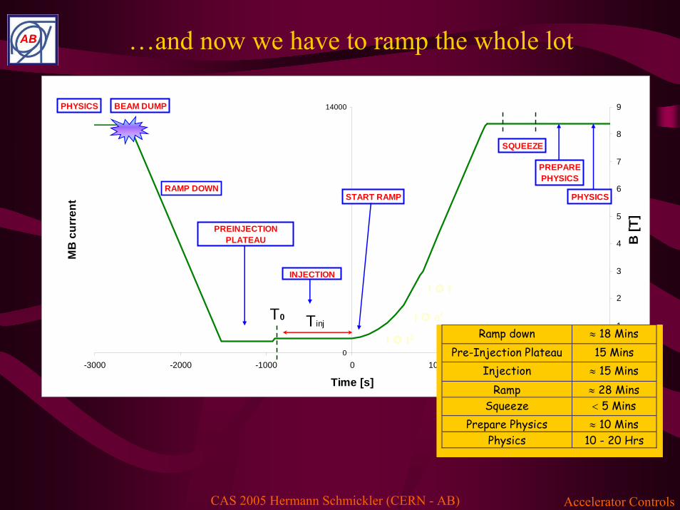
…and now we have to ramp the whole lot
0
14000
-3000 -2000 -1000 0 1000 2000 3000
Time [s]
MB
cur
rent
0
1
2
3
4
5
6
7
8
9
B [T
]
RAMP DOWNSTART RAMP
PHYSICS
PREPAREPHYSICS
BEAM DUMP
PREINJECTIONPLATEAU
INJECTION
T0 Tinj
SQUEEZE
PHYSICS
Ramp down ≈ 18 Mins Pre-Injection Plateau 15 Mins
Injection ≈ 15 Mins Ramp ≈ 28 Mins
Squeeze < 5 Mins Prepare Physics ≈ 10 Mins
Physics 10 - 20 Hrs
I t2
I et
I t
Accelerator ControlsCAS 2005 Hermann Schmickler (CERN - AB)
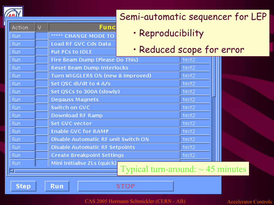
Typical turn-around: ~ 45 minutes
Semi-automatic sequencer for LEP
• Reproducibility
• Reduced scope for error

Accelerator ControlsCAS 2005 Hermann Schmickler (CERN - AB)
Accelerator ControlsCAS 2005 Hermann Schmickler (CERN - AB)
0
5000
10000
15000
-2000 0 2000 4000 6000
time from beginning of injection (s)
dipo
le c
urre
nt (A
)
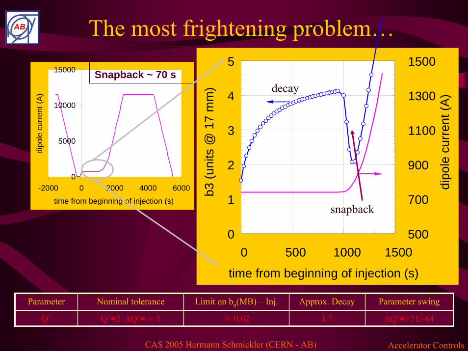
Injection ~ 1200 s
Snapback ~ 70 s
Parameter Nominal tolerance Limit on bn(MB) – Inj. Approx. Decay Parameter swing
1.7 ΔQ’≈+71/-64 0.02Q’ Q’≈2 ΔQ’≈ 1
The most frightening problem…
0
1
2
3
4
5
0 500 1000 1500
time from beginning of injection (s)
b3 (u
nits
@ 1
7 m
m)
500
700
900
1100
1300
1500
dipo
le c
urre
nt (A
)decay
snapback

Accelerator ControlsCAS 2005 Hermann Schmickler (CERN - AB)
Chromaticity
• The measured chromaticity is the sum of: →Correct natural with lattice sextupoles →Would aim to balance Q’-b3-dipole with Q’-b3-spool→Watch other (e.g. insertion quads – own correctors)
• Signature of improperly compensated b3 error is clear: →0.1 unit b3 → +3/-3.5 Q’h/Q’v
• We should be able to measure periodically on injection plateau to verify corrections.
'3
'3
'3
''''otherbspoolbdipolebsextlatticenaturalmeastotal QQQQQQQ −−−− ++++==

Accelerator ControlsCAS 2005 Hermann Schmickler (CERN - AB)
Per aperture:
154 MCS sextupole spool pieces powered in series.
77 MCO & MCD spool pieces powered in series.
Therefore we’re working on the average per sector per aperture
Correction elements
Accelerator ControlsCAS 2005 Hermann Schmickler (CERN - AB)
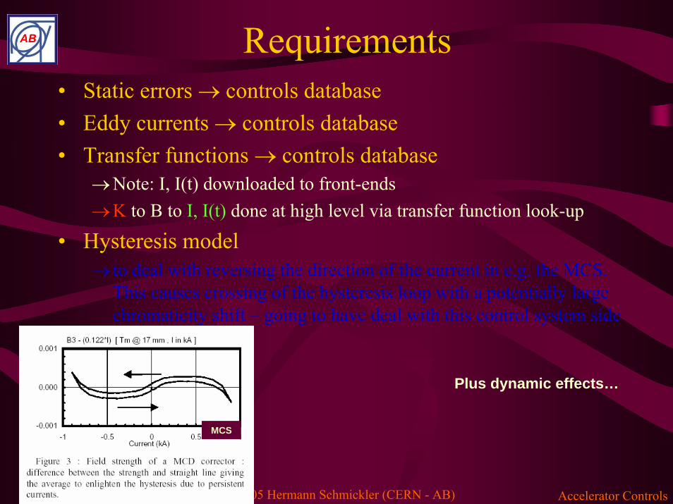
Requirements• Static errors → controls database• Eddy currents → controls database• Transfer functions → controls database
→Note: I, I(t) downloaded to front-ends→K to B to I, I(t) done at high level via transfer function look-up
• Hysteresis model → to deal with reversing the direction of the current in e.g. the MCS.
This causes crossing of the hysteresis loop with a potentially large chromaticity shift – going to have deal with this control system side
Plus dynamic effects…
MCS
Accelerator ControlsCAS 2005 Hermann Schmickler (CERN - AB)
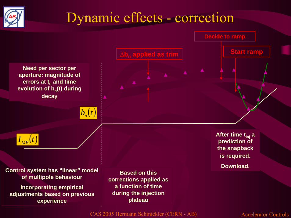
( )tbn
Control system has “linear” model of multipole behaviour
Incorporating empirical adjustments based on previous
experience
▲
▲▲
▲ ▲ ▲ ▲ ▲
Δbn applied as trim
Decide to ramp
▲
▲
▲
▲
▲
▲▲Need per sector per aperture: magnitude of
errors at t0 and time evolution of bn(t) during
decay
Based on this corrections applied as
a function of time during the injection
plateau
After time tinj a prediction of the snapback is required.Download.
Start ramp
( )tIMB
Dynamic effects - correction

Accelerator ControlsCAS 2005 Hermann Schmickler (CERN - AB)
Snapback – Q’
• Fit snapback:
• I(t) – MB current at time t• Iinjection – injection value of current• Δb3 and ΔI are fitting constants
• Δb3 and ΔI are correlated
( )( )
IItI
snapbackinjection
ebtb Δ
−−
Δ= 33
If b3 amplitude can be measured “on-line” the SB fit can be predicted w/out use of “multi-parameter” algorithm
Sextupole compensation during snap-back in collaboration with FNAL – Luca Bottura
Accelerator ControlsCAS 2005 Hermann Schmickler (CERN - AB)
Q’ - snapback• Extract sextupole change in dipoles from slow Q’
measurements & b3 corrections during injection to give Δb3 and thus ΔI.
• Just before ramping:→Extract total b3 correction→Invoke fit for snapback prediction→Convert to currents→Incorporate into ramp functions & download
• Functions invoked at ramp start by standard timing event
Accelerator ControlsCAS 2005 Hermann Schmickler (CERN - AB)
…and if all this is not enough: real time feedbacks on beam parameters
• Time resolved measurements- LHC orbit: minimum 10 Hz- LHC betatron tunes: some Hz- LHC chromaticties: Hz
• Data centralization and computation of corrections(including error handling, dynamic change of twiss parameters…
• Feedback of corrections to power converters
Nice Problem for the instrumentation
group

53
Orbit FB Control Layout
...
Orbit FeedbackControllerBPM-Crate PC-Gateway
Ethernet UDP/IP
18 BPMs/crate 16 CODs/gateway
BPM-Crate
BPM-Crate
...BPM-Crate
PC-Gateway
PC-Gateway
PC-Gateway
...Service Unit
Database settings,operation, users
SurfaceTunnel
...
feedback unit64 crates ~50 cratesEthernet UDP/IP
Central FB unit has 2 functional parts• Time-critical controller unit to compute the corrections (hard
real-time).• A Service Unit for DB and user interfaces, matrix operations,
sanity checks..The total loop delay is expected to be stable at ~ 60-80 ms

Accelerator ControlsCAS 2005 Hermann Schmickler (CERN - AB)
LEP feedback on tunes
Time dependent reference for tunes!
Accelerator ControlsCAS 2005 Hermann Schmickler (CERN - AB)
Summary
• Accelerator Controls is a vast activity• Controls Hardware mainly based on commercially
available products (COTS)• Controls of beam parameters makes the link
between:- accelerator physics
- beam observation- equipment control
• …is fun to work on…


![CRYO-COOLING: why and how? · 2019. 12. 2. · Radiation damage. –Optimising cryoprotection. ... polyimide film. MiTeGen [Thorne et al (2003), JAPC 36, 1455.] Rayon loops Hampton](https://static.fdocuments.in/doc/165x107/60e12d61fc199e647913a87e/cryo-cooling-why-and-how-2019-12-2-radiation-damage-aoptimising-cryoprotection.jpg)


