NL SERIES - dolas.cz · The milling mechanism on conventional lathes generates a great deal of ......
56
NL SERIES NL SERIES CNC Lathe Rigid and Precise CNC Lathe
Transcript of NL SERIES - dolas.cz · The milling mechanism on conventional lathes generates a great deal of ......

NL SERIES
NL SERIES
CNC Lathe
Rigid and Precise CNC Lathe
2
Ever since our first machine tool rolled off the
production line in 1968, we here at Mori Seiki have
continued to make CNC lathes that are praised by
customers everywhere. Over those 35 years, we
have released around 100 models. We can say with
confidence that we believe every single one was an
improvement on its predecessor. So Mori Seiki
has been able to create a new generation of CNC
lathes, a lathe that moves the world. By reviewing
the structure of every feature, by confronting the
problem of heat generation, by reflecting on a
product which incorporates all the customers’
many demands. Through uncompromising
development, we have achieved previously unheard
of levels of rigidity, accuracy and reliability. Our
efforts have created our newest line, the NL Series.
These new machines are high-rigidity, high-
precision CNC lathes and set the new standard in
“common sense” machining for a new age.
Innovative turret design P.4-7
The ultimate in turning P.8-9
Rigid base P.10-11
Thermal isolation P.12-13
Variations P.14-15
Y-axis specifications P.16
Digital tailstock P.17
Distance between centers 2000 type, 3000 type P.18-19
Machining power P.20-21
Productivity P.22-23
Maintenance P.24-25
Convenience P.26
Eco-friendly design P.27
Peripheral equipment P.28-31
MAPPSⅢ(a new high-performance operating system) P.32-35
Turnkey systems P.36-37
Service Network P.38-39
Standard & optional features P.40-46
Recommended specifications P.47
Numerical control unit specifications (MSX-850Ⅲ) P.48
Machine size P.49
Machine specifications P.50-55
A l a t h e w h i c h m o v e s t h e w o r l d .
MAPPS:Mori Advanced Programming Production System● Figures in inches were converted from metric measurements.
Rigid & Precise

3
Rigid and Precise CNC Lathe NL SERIESNL SERIESNL1500/NL2000/NL2500/NL3000
The 34th Nikkan Kogyo Shimbun 2004 Machine Design AwardJapan Machine Tool Builders’ Association Award
4
Rigid & PreciseNL SERIES
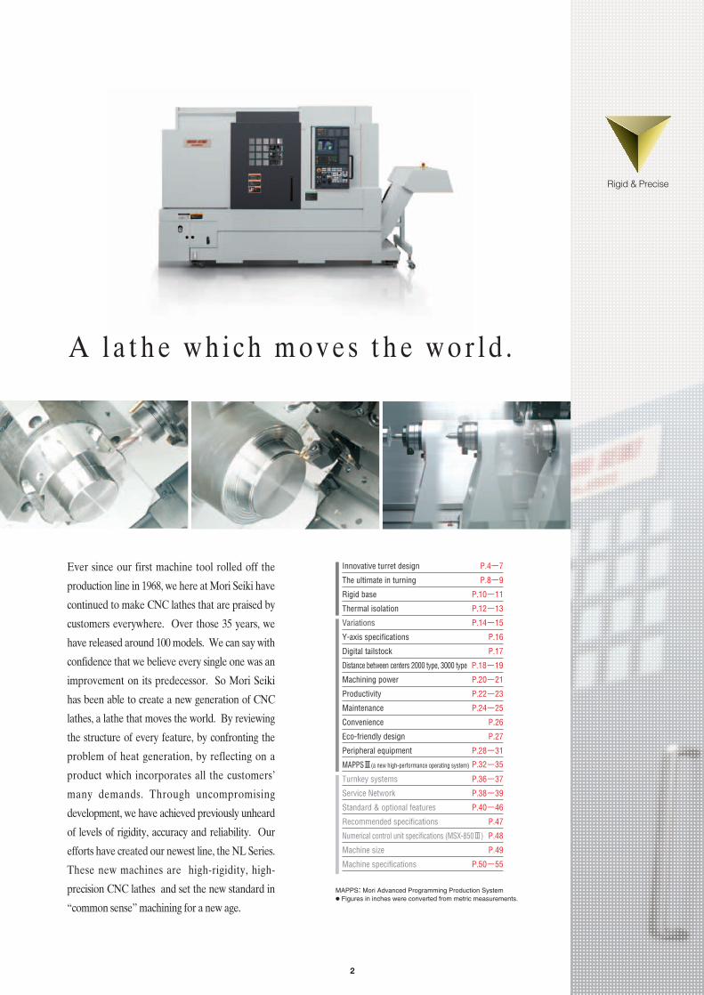
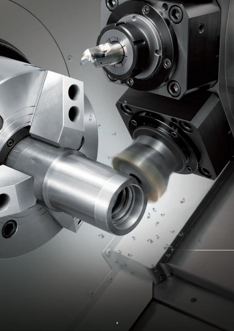
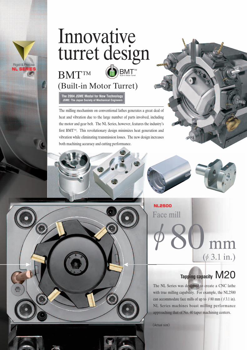
The NL Series was designed to create a CNC lathe
with true milling capability. For example, the NL2500
can accommodate face mills of up to φ80 mm (φ3.1 in).
NL Series machines boast milling performance
approaching that of No. 40 taper machining centers.
φ80 mm
Face millNL2500
《Actual size》
Tapping capacity M20
BMTTM
(Built-in Motor Turret)The 2004 JSME Medal for New TechnologyJSME: The Japan Society of Mechanical Engineers
5
Innovative turret design
The milling mechanism on conventional lathes generates a great deal of
heat and vibration due to the large number of parts involved, including
the motor and gear belt. The NL Series, however, features the industry’s
first BMTTM. This revolutionary design minimizes heat generation and
vibration while eliminating transmission losses. The new design increases
both machining accuracy and cutting performance.
(φ3.1 in.)

Extremely rigid turretIn order to enhance the milling function, it is essential to increase
the rigidity of the rotary tool holders. The NL Series rotary tool
holders have a broader grip compared to conventional lathes. By
raising attachment precision we have vastly improved rigidity.
■ Comparison of rotary tool holder rigidity
■ Coupling diameter
With conventional lathes, chatteringoccurred when the depth of cut wasincreased. The NL Series, however, isequipped with rotary tool holders withimproved rigidity, allowing deeper cuttingthan before.
Greater coupling diameter than before.
■ Super-rigid rotary tool holders
Taking a hint from couplings,which are praised for their highrepeatability, we developed avery rigid rotary tool holder.
Strong grippingforce is secured bythe 3 positioningkeys.
NL2500
Tool diameter and depth of cut
Tool diameter and depth of cut
10-15 mm(0.4-0.6 in.)
20 mm(0.8 in.)
26 mm (1.0 in.)<Max.> 20 mm (0.8 in.)
<Max.>
Previous model
6
Coupling diameter
19% Greater
210 mm(8.3 in.)
250 mm(9.8 in.)
NL2500Previous model
Positioning key
Tool diameter
26 mm (1.0 in.)<Max.>
Depth of cut
20 mm (0.8 in.)<Max.>
Rotary tool holder rigidity
180% Greater
X The cutting test results indicated in this catalog are provided as examples. The results indicated in thiscatalog may not be obtained due to differences in cutting conditions and environmental conditions duringmeasurement.

7
DDS: Direct Drive Spindle
■ High-performance rotary tool spindleA DDS motor that has no gear belt is used for the rotary toolspindle, delivering high-speed, high-efficiency machining.
NL SERIES
Max. rotary tool spindle speed
6,000min-14,000 min-1
Previous model
NL2500
Rotary tool spindle acceleration time
0→4,000 min-10→4,000 min-1
0.11sec.0.35 sec.
Previous model
Maximum rotary tool spindle torque
Rigid & PreciseNL SERIES
0→6,000 min-1
0.23 sec.
50% Greater
Reduced approximately 70%
NL1500 24 N·m (17.7 ft·lbf)<3 min>
29 N·m (21.4 ft·lbf)<3 min>
40 N·m (29.5 ft·lbf)<3 min>
54 N·m (39.8 ft·lbf)<10 min>
NL2000
NL3000
NL2500NL3000
Turret equipped with quick-change specifications forVDI tools. Tool attachment time is dramaticallyreduced.
■ Turret variationsQuick-change type turret head (VDI)
The Coromant Capto modular toolingsystem, with much faster tool-changingtime than conventional machines.
Capto-compatible holder
Equipped with the bolt-fastened type,10-station turret from the NL3000.
10-station turret head (NL3000)
OptionOP
Face type
X The face type is only available for 2-axis turning specifications.
Including outercircumference
A 20-station turret for workpieces whichrequire many machining processes, orfor various types of workpieces.
20-station turret head (NL1500, NL2000)
OPOPOP
OP

8
By increasing the rigidity between the spindle and tool tip, tool
tip vibration has been minimized, achieving a high-quality cutting
surface during turning. At the same time, tool tip vibration control
also contributes to longer tool life.
■ O.D. rough cutting
■ Grooving
Width of groove
9 mm(0.35 in.)
Machine typeToolMaterial <JIS>Cutting speedFeedrateWidth of groove
NL2000MC/500ISCAR GFN9 IC354S45C (Carbon steel)190 m/min (623.4 fpm)0.25 mm/rev (0.010 ipr)9 mm (0.35 in.)
Machine typeToolMaterial <JIS>Cutting speedFeedrateDepth of cut
NL3000Y/700SANDVIK CNMM190616-PR4025S45C (Carbon steel)220 m/min (721.8 fpm)0.6 mm/rev (0.024 ipr)10 mm (0.4 in.)
《Actual size》
《Actual size》
Depth of cut
10 mm(0.4 in.)
The ultimatein turningImproved tool tip rigidity
9
Rigid & PreciseNL SERIES
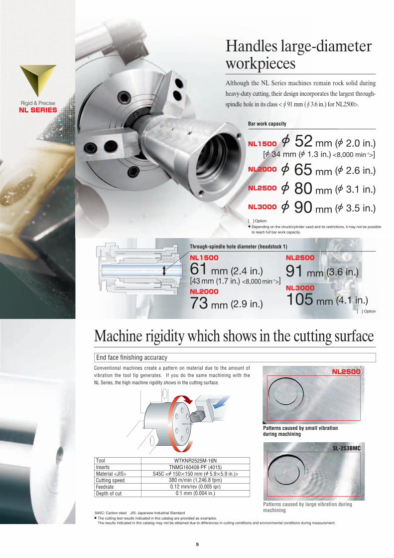
Handles large-diameterworkpiecesAlthough the NL Series machines remain rock solid during
heavy-duty cutting, their design incorporates the largest through-
spindle hole in its class <φ91 mm (φ3.6 in.) for NL2500>.
SL-253BMC
Patterns caused by small vibration during machining
Patterns caused by large vibration duringmachining
Machine rigidity which shows in the cutting surface
NL2500Conventional machines create a pattern on material due to the amount of vibration the tool tip generates. If you do the same machining with the NL Series, the high machine rigidity shows in the cutting surface.
S45C: Carbon steel JIS: Japanese Industrial Standard
X The cutting test results indicated in this catalog are provided as examples. The results indicated in this catalog may not be obtained due to differences in cutting conditions and environmental conditions during measurement.
NL1500
NL2000 NL3000
61 mm (2.4 in.)
73 mm (2.9 in.)
NL2500
91 mm (3.6 in.)
105 mm (4.1 in.)
Through-spindle hole diameter (headstock 1)
Bar work capacity
A 52 mm (A 2.0 in.)[A 34 mm (A 1.3 in.) <8,000 min-1>]
[43 mm (1.7 in.) <8,000 min-1>]
NL1500
NL2000 A 65 mm (A 2.6 in.)
A 80 mm (A 3.1 in.)NL2500
A 90 mm (A 3.5 in.)NL3000
X Depending on the chuck/cylinder used and its restrictions, it may not be possible
to reach full bar work capacity.
[ ]Option
End face finishing accuracy
ToolInsertsMaterial <JIS>Cutting speedFeedrateDepth of cut
WTKNR2525M-16NTNMG160408-PF (4015)
S45C <A 150×150 mm (A 5.9×5.9 in.)>380 m/min (1,246.8 fpm)0.12 mm/rev (0.005 ipr)
0.1 mm (0.004 in.)
[ ] Option
10
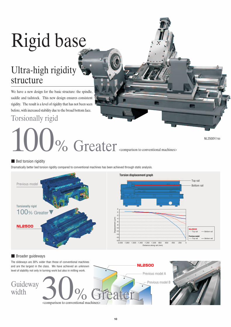
■ Broader guidewaysThe slideways are 30% wider than those of conventional machinesand are the largest in the class. We have achieved an unknownlevel of stability not only in turning work but also in milling work.
NL2500
Guidewaywidth 30% Greater
Torsionally rigid
100% GreaterNL2500Y/700
Previous model
■ Bed torsion rigidity
NL2500
Dramatically better bed torsion rigidity compared to conventional machines has been achieved through static analysis.
Top rail
Bottom rail
Torsion displacement graph
30% Greater<comparison to conventional machines>
Torsionally rigid
100% Greater
Rigid base
We have a new design for the basic structure: the spindle,
saddle and tailstock. This new design ensures consistent
rigidity. The result is a level of rigidity that has not been seen
before, with increased stability due to the broad bottom face.
Ultra-high rigiditystructure
<comparison to conventional machines>
-18
-16
-14
-12
-10
-8
-6
-4
-2
0
2
-2,000 -1,800 -1,600 -1,400 -1,200 -1,000 -800 -600 -400 -200 0
Dis
plac
emen
t (μ
m)
Distance along rail (mm)
Top rail
Top rail
Bottom rail
Bottom rail
NL2500
Previous model
Previous model A
Previous model B

Highly rigid spindleThe axis rigidity of the headstock and its mounting have been improved by changing the shape of the headstock and
increasing the thickness of its parts. The diameter of the bearings has been increased. This allows better spindle rigidity
while enlarging the through-hole diameter.Rigid & PreciseNL SERIES
Rigidity of the spindle itself
NL2500
Acceleration/deceleration time (when mounted with chuck)
Spindle acceleration time(0→4,000 min-1)
Spindle acceleration time(0→4,000 min-1)
Spindle deceleration time(4,000 min-1→0)
3.4 sec.4.9 sec.
Spindle deceleration time(4,000 min-1→0)
4.2 sec.
Previous model
3.6 sec.
NL1500
Maximum spindle torque (standard)
NL2000
NL2500
NL3000
200 N·m (147.5 ft·lbf) <50%ED>
349 N·m (257.4 ft·lbf) <50%ED>
599 N·m (441.8 ft·lbf) <25%ED>
1,025 N·m (756.0 ft·lbf) <30 min>
■ Improved acceleration/deceleration time and torque specsRaising the rigidity has endowed the NL Series with performance equal to that of spindle motors one class above.
11
50% Greater
Reduced by31%
Reduced by14%
<comparison to conventional machines>
Axis rigidity 20% Greater
Headstock attachment rigidity
30% Greater
12
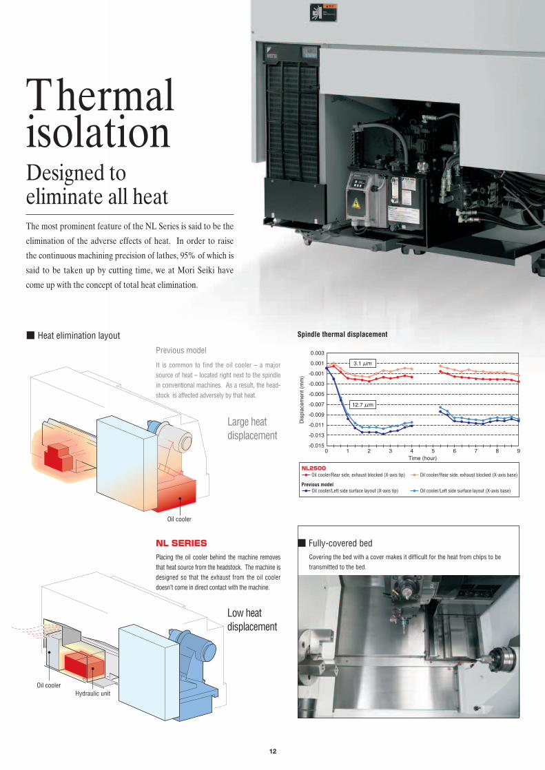
■ Heat elimination layout
Thermalisolation
The most prominent feature of the NL Series is said to be the
elimination of the adverse effects of heat. In order to raise
the continuous machining precision of lathes, 95% of which is
said to be taken up by cutting time, we at Mori Seiki have
come up with the concept of total heat elimination.
Designed to eliminate all heat
NL SERIES
Previous model
It is common to find the oil cooler – a majorsource of heat – located right next to the spindlein conventional machines. As a result, the head-stock is affected adversely by that heat.
Placing the oil cooler behind the machine removesthat heat source from the headstock. The machine isdesigned so that the exhaust from the oil coolerdoesn’t come in direct contact with the machine.
Large heat displacement
Low heat displacement
Oil cooler
Oil cooler
■ Fully-covered bed
Spindle thermal displacement
Covering the bed with a cover makes it difficult for the heat from chips to be
transmitted to the bed.
Hydraulic unit
Dis
plac
emen
t (m
m)
-0.003
-0.005
-0.007
-0.009
-0.011
-0.013
-0.015
-0.001
0.001
0.003
Time (hour)0 1 2 3 4 5 6 7 98
Oil cooler/Rear side, exhaust blocked (X-axis tip)
Oil cooler/Left side surface layout (X-axis tip)
Oil cooler/Rear side, exhaust blocked (X-axis base)
Oil cooler/Left side surface layout (X-axis base)
3.1 μm
12.7 μm
NL2500
Previous model

Rigid & PreciseNL SERIES
13
Oil jacket
Spindle coolingWe have redesigned the spindle, which is
the greatest source of heat, to employ a
uniform-heat construction that maintains an equal
temperature all around the spindle. The main spindle
unit is protected from rises in temperature by the
spiraling oil jacket located all the way to the back side.
Milling turret with a heat-suppressing designThe industry’s first BMTTM (Built-in Motor Turret) minimizes heat.
Inverter-type oil cooler
An inverter-type oil cooler with veryaccurate temperature regulation hasbeen used.
1/10Rising turret temperatures
NL SERIESInternal design of the turret
Oil jacket
Built-in milling motor
Ball screw shaft cooling (option)As an option to increase machining accuracy even further, we have provided
ball screw core cooling. (X-axis only)
Motor
Timing belt 1
Timing belt 2
Bevel gear
Keyed shaft
+
+
+Involuted spline
+
+
Built-in milling motor
Keyed shaft+
Previous model NL SERIES
The transmission with all its gear, belts, andmore, generates a substantial amount of heatand can adversely affect machining precision.
The built-in milling motor design haseliminated the transmission mechanism.Therefore, sources of heat are eliminatedand jacket cooling is performed. This isonly achieved with a built-in millingmotor.
NL SERIES Internal design of the spindle
or less

14
VariationsRigid & Precise
NL SERIES
We want everyone to use the new standard in CNC lathes.
Mori Seiki’s NL Series has machines in four classes for different
workpiece sizes and six types to best match the level of the
customer’s machining and process integration. With a total of
36 variations, you are bound to find one right for you.
NL1500MC Y S SMC SY
Distance between centers
Standard chuck size<headstock 1/headstock 2>
Number of tool stations
Travel <X-/Z-axis>
Travel <Y-axis>
500
6 inches /
/
6 inches
12 [16] [20] tools
Bar work capacity52 mm (2.0 in.)
[34 mm (1.3 in.) <8,000 min-1>]
260/590 mm (10.2/23.2 in.)
100 <±50> mm (3.9 <±2.0> in.)
NL2000MC Y S SMC SY
Distance between centers
Standard chuck size<headstock 1/headstock 2>
Number of tool stations
Travel <X-/Z-axis>
Travel <Y-axis>
500
8 inches 6 inches
12 [10] [16] [20] tools
Bar work capacity 65 mm (2.5 in.)
260/590 mm (10.2/23.2 in.)
100 <±50> mm (3.9 <±2.0> in.)
[ ] Option
[ ] Option
● Bar work capacity: depending on the chuck/cylinder used and its restrictions, it may not be possible to reach full bar work capacity. ● The photo shows the machine equipped with options.
36variations
in all
36variations
in all
2-axis turning
2-axis turning
NL1500MC/500
NL2000SMC/500
15
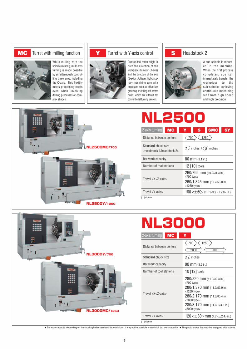
S Headstock 2
A sub-spindle is mount-ed in the machine.When the first processcompletes, you canimmediately transfer theworkpiece to the sub-spindle, achievingcontinuous machiningwith both high speedand high precision.
MC Turret with milling function
While milling with thespindle rotating, multi-axisturning is made possibleby simultaneously control-ling three axes, includingthe C-axis. This flexiblymeets processing needseven when involvingdrilling processes or com-plex shapes.
Y Turret with Y-axis control
Controls tool center height inboth the direction of the workpiece diameter (X-axis)and the direction of the axis(Z-axis). Achieves high-accu-racy machining even withprocesses such as offset keygrooving or drilling off-centerholes, which are difficult forconventional turning centers.
NL2500
700 1250
2000 3000
NL3000MC Y
Distance between centers
Standard chuck size
Number of tool stations
Travel <X-/Z-axis>
Travel <Y-axis>
12 inches
10 [12] tools
Bar work capacity 90 mm (3.5 in.)
280/820 mm (11.0/32.3 in.)<700 type>
280/1,370 mm (11.0/53.9 in.)<1250 type>
280/2,170 mm (11.0/85.4 in.)<2000 type>
280/3,170 mm (11.0/124.8 in.)<3000 type>
120 <±60> mm (4.7 <±2.4> in.)
[ ] Option
● Bar work capacity: depending on the chuck/cylinder used and its restrictions, it may not be possible to reach full bar work capacity. ● The photo shows the machine equipped with options.
2-axis turning
NL2500MC/700
NL2500Y/1250
NL3000Y/700
NL3000MC/1250
/ 6 inches
MC Y S SMC SY2-axis turning
Distance between centers
Standard chuck size<headstock 1/headstock 2>
Number of tool stations
Travel <X-/Z-axis>
Travel <Y-axis>
700 1250
10 inches
12 [10] tools
Bar work capacity 80 mm (3.1 in.)
260/795 mm (10.2/31.3 in.)<700 type>
260/1,345 mm (10.2/53.0 in.)<1250 type>
100 <±50> mm (3.9 <±2.0> in.)
[ ] Option

NL1500/NL2000/NL2500
±50mm (±2.0 in.)NL3000
±60mm (±2.4 in.)
Y-axis travel
■ Bar machining with Y-axis control
16
a
a
● Grooving
Y-axis (ー)
Y-axis (+)
X-axis (ー)
X-axis (+)
X-axis (+)
Spindle centerSpindle centerSpindle center
Y-axis (ー)
Y-axis (+)
X-axis (ー) a
a
a
a
Spindle center
● Contouring
X-axis (+)
X-axis (+)
XPoints “a”, intersections between the workpiece center line and theprofile to be machined.
Quadrant projection (a)Polar coordinate interpolation
Y-axis control
On a conventional turning center, polar coordinate interpolation isused for tool motion control during grooving and contouring, asillustrated in the left figure. In this control mode, however, the X-axis travel direction is reversed at points “a”, the intersectionsbetween the workpiece center line and the profile to be machined.This reversal changes cutting conditions and subsequently effectsprofile accuracy. Machining with Y-axis control, on the other hand,is free of such changes and ensures a high level of profile accuracy.
Linking the X-axis and a virtual axis createsthe Y-axis movement. The axis unit has beendownsized to lower machine height.
■ Comparison between polar coordinate interpolation and Y-axis control■ Circumferential grooving on a turning center with
Y-axis control
ab
Milling without Y-axis controlIt is hard to match the width of outer (a) andinner (b) grooves.
Milling on the NL SeriesGroove width can be matched using Y-axis control.
Y-axis specificationsWe also independently developed a powerful platform for maximizing perform-ance in the Y-axis specifications. This has achieved rigidity between the spindleand the tool tip that exceeds that of conventional two-axis lathes.
Y SY
Z1-axis
Y-axis
X1-a
xis
Side milling Off-center grooving Off-center drilling

17
Reducedby over 50%
Setup time
Reducedby over 20%
Tailstock spindle operating time
Tailstock control screen
Machining using the tailstock drill (option)
With a servomotor for positioning, the digital tailstockhas outstanding functionality. It can also be used forcertain types of machining (e.g., drilling, boring) ofthe center of the workpiece end face.
■ More applications
The operator is freed from the hassle of having to lock the tailstock whenchanging to a workpiece of a different length, connecting it to the turret, etc.
■ Fewer steps requiring operation of the tailstock
With the conventional hydraulic system, changing the tailstock spindle settings wasinconvenient, so there was a limit to how much operating time could be reduced. A digitaltailstock with variable feed speed control allows separate speeds to be set for approachand engagement, reducing the operating time of the tailstock spindle by over 20%.
■ Operating time reduced
With a hydraulic tailstock spindle, thrust is controlled indirectly using a hydraulic pressuremeter, so if you use different machine models, you will get different thrusts even if thesame pressure is set. With a digital tailstock, however, the thrust is measured directly,so the workpiece engagement is done accurately, raising machining precision.
■ Variable pressure control using program instructions
Approach position, retract position, re-chucking and more can be done simply andeasily from the MAPPSⅢ screen. Besides being able to handle a variety of differentworkpiece types, it can also work with M-code thrust selection as a standard feature.
■ Simple operation using MAPPSⅢ
X The NL3000 with a distance between centers of 2000 type, 3000 type is equipped with aprogrammable tailstock (carriage direct-coupled) as standard.
Digital tailstockThe NL Series comes standard with a new feature – a highly rigid digital tailstockdriven by a servo motor. This drastically reduces setup time. (New standard featuredoes not apply to S, SMC and SY types.)
77.8 N·m (57.4 ft·lbf) <25%ED>
NL SERIES
Maximum headstock 2 torque
Headstock 2Choose from S-type, which allows both-face continuous machining, SMC-typewhich offers consistent machining from turning to secondary machining and backface machining thanks to its combination of headstock 2 and rotary tools, and SY-type, which achieves superior multi-axis machining with the additional Y-axis.
MC Y Not including NL3000/2000, NL3000/30002-axis turning
S SMC SY
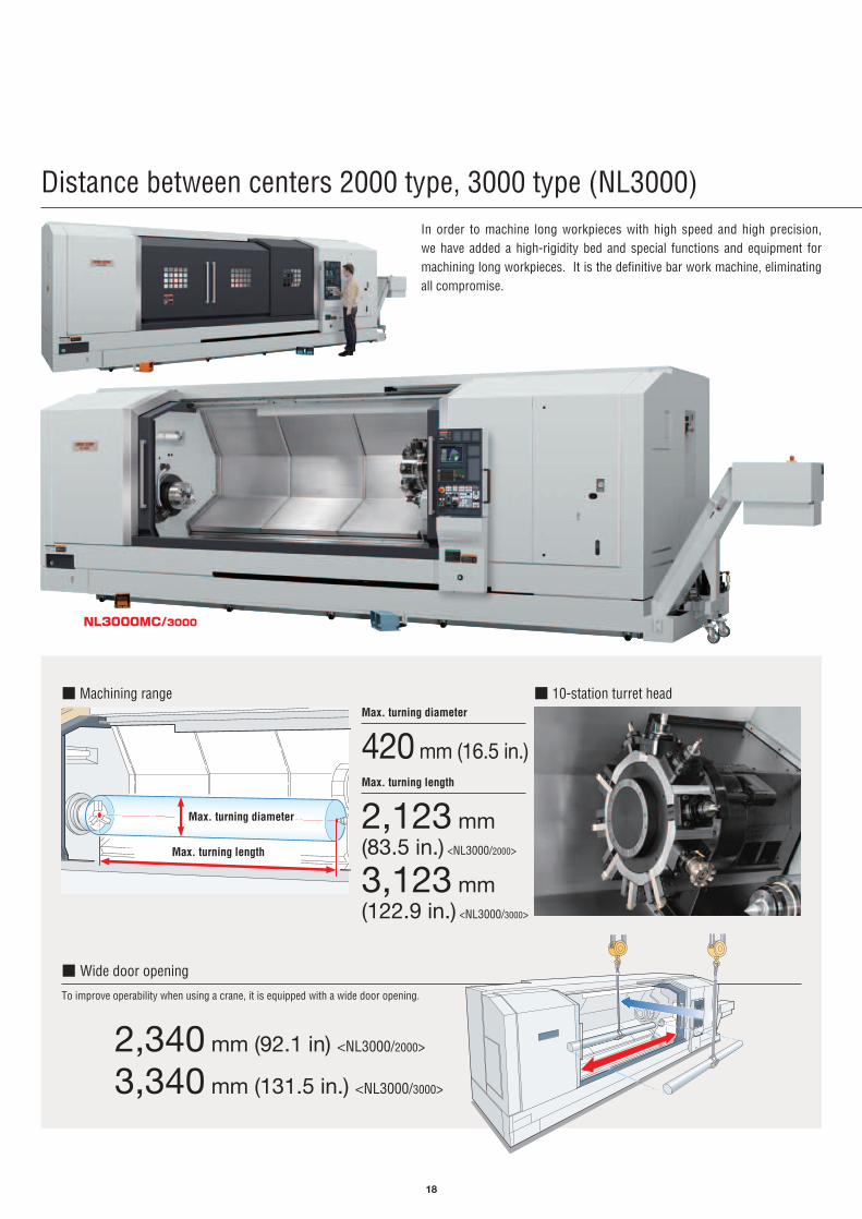
Distance between centers 2000 type, 3000 type (NL3000)
Max. turning diameter
420 mm (16.5 in.)
2,340 mm (92.1 in) <NL3000/2000>
3,340 mm (131.5 in.) <NL3000/3000>
■ Wide door opening
To improve operability when using a crane, it is equipped with a wide door opening.
Max. turning length
2,123 mm (83.5 in.) <NL3000/2000>
3,123 mm (122.9 in.) <NL3000/3000>
■ Machining range ■ 10-station turret head
18
In order to machine long workpieces with high speed and high precision, we have added a high-rigidity bed and special functions and equipment formachining long workpieces. It is the definitive bar work machine, eliminatingall compromise.
NL3000MC/3000
Max. turning diameter
Max. turning length
19
NL3000/2000, NL3000/3000
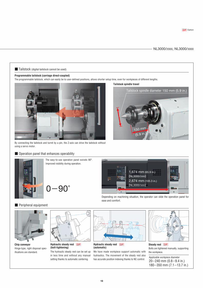
Hydraulic steady rest(bolt-tightening)The hydraulic steady rest can be set upin less time and without any manualsetting thanks to automatic centering.
Steady restBolts are tightened manually, supportingthe workpiece.
Hydraulic steady rest(automatic)We have made workpiece support automatic withhydraulics. The movement of the steady rest alsohas accurate position indexing thanks to NC control.
■ Peripheral equipment
Chip conveyorHinge-type, right disposal spec-ifications are standard.
■ Tailstock (digital tailstock cannot be used)
Programmable tailstock (carriage direct-coupled)The programmable tailstock, which can easily be to user-defined positions, allows shorter setup time, even for workpieces of different lengths.
Tailstock spindle travel
By connecting the tailstock and turret by a pin, the Z-axis can drive the tailstock withoutusing a servo motor.
150 mm150 mm
(5.9 in.)
Depending on machining situation, the operator can slide the operation panel forease and comfort.
■ Operation panel that enhances operability
1,674 mm (65.9 in.)
(NL3000/2000)2,674 mm (105.3 in.)
(NL3000/3000)
The easy-to-use operation panel swivels 90°.Improved visibility during operation.
0-90°
150 mm
Tailstock spindle diameter 150 mm (5.9 in.)
Applicable workpiece diameter20-240 mm (0.8-9.4 in.)180-350 mm (7.1-13.7 in.)
OP OP OP
OptionOP
20
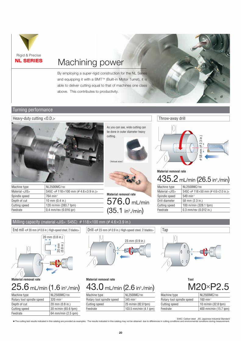
Machining powerRigid & Precise
NL SERIES
By employing a super-rigid construction for the NL Series
and equipping it with a BMTTM (Built-in Motor Turret), it is
able to deliver cutting equal to that of machines one class
above. This contributes to productivity.
Machine typeMaterial <JIS>Spindle speedDepth of cutCutting speedFeedrate
Heavy-duty cutting <O.D.> Throw-away drill
NL2500MC/700
S45C <A 118×100 mm (A 4.6×3.9 in.)>764 min-1
10 mm (0.4 in.)120 m/min (393.7 fpm)0.4 mm/rev (0.016 ipr)
Material removal rate
576.0 mL/min
(35.1 in3./min)
Material removal rate
435.2 mL/min (26.5 in3./min)
As you can see, wide cutting canbe done in outer diameter heavycutting.
Machine typeMaterial <JIS>Spindle speedDrill diameterCutting speedFeedrate
Milling capacity (material <JIS>: S45C) A 118×100 mm (A 4.6×3.9 in.)
NL2500MC/700
S45C <A 118×50 mm (A 4.6×2.0 in.)>549 min-1
58 mm (2.3 in.)100 m/min (328.1 fpm)0.3 mm/rev (0.012 in.)
《Actual size》
Turning performance
End mill <A 20 mm (A 0.8 in.) High-speed steel, 2 blades> Drill <A 23 mm (A 0.9 in.) High-speed steel, 2 blades> Tap
Machine typeRotary tool spindle speedDepth of cutCutting speedFeedrate
NL2500MC/700
320 min-1
20 mm (0.8 in.)20 m/min (65.6 fpm)64 mm/min (2.5 ipm)
Machine typeRotary tool spindle speedCutting speedFeedrate
NL2500MC/700
345 min-1
25 m/min (82.0 fpm)103.5 mm/min (4.1 ipm)
Machine typeRotary tool spindle speedCutting speedFeedrate
NL2500MC/700
160 min-1
10 m/min (32.8 fpm)400 mm/min (15.7 ipm)
S45C: Carbon steel JIS: Japanese Industrial Standard ● The cutting test results indicated in this catalog are provided as examples. The results indicated in this catalog may not be obtained due to differences in cutting conditions and environmental conditions during measurement.
Material removal rate
25.6 mL/min (1.6 in3./min)Material removal rate
43.0 mL/min (2.6 in3./min)Tool
M20×P2.5
20 mm (0.8 in.)23 mm (0.9 in.)
A58
mm
(A2.
3 in
.)
20 m
m
(0.8
in.)

21
Previous model
Comparison of milling power (material <JIS>: S45C)
End mill Drill
Depth of cut15 mm (0.6 in.) 20 mm (0.8 in.)
Material removal rate8.6 mL/min
(0.5 in3./min)38.4 mL/min (2.3 in3./min)
NL2500MC/700 Previous modelDrill diameter
Machine type Machine type
20 mm (0.8 in.) 24 mm (0.9 in.)Material removal rate
12.6 mL/min(0.8 in3./min)
45.1 mL/min (2.8 in3./min)
NL2500MC/700
Compared against previous model A
Reduced by 30 sec.Compared against previous model B
Reduced by 29 sec.
Compared against previous model C
Reduced by 65 sec.Compared against previous model D
Reduced by 69 sec.
Compared against previous model E
Reduced by 30 sec.Compared against previous model F
Reduced by 32 sec.
Compared against previous model G
Reduced by 46 sec.
X The maximum machining ability shown above is for short-term machining. S45C: Carbon steel JIS: Japanese Industrial StandardX The cutting test results indicated in this catalog are provided as examples. The results indicated in this catalog may not be obtained due to differences in cutting conditions and environmental conditions during measurement.
Machining power Approx. 4 times
Comparison of cutting time
Roundness (turning)
6-inch chuck machine
Previous model A
Previous model C Previous model D
Previous model BNL1500Cutting timeNon-cutting timeTotal time
14926
175
26316842
473
39228
420
84740
887
14925
174
12421145
21914940408
36624390
81031841
<sec.><sec.><sec.>
<sec.><sec.><sec.><sec.>
<sec.><sec.><sec.>
<sec.><sec.><sec.>
26416845477
39032
422
10-inch chuck machine
Previous model E Previous model FNL2500
12-inch chuck machine
Previous model GNL3000
8-inch chuck machine
NL2000Cutting timeMilling timeNon-cutting timeTotal time
Cutting timeNon-cutting timeTotal time
Cutting timeNon-cutting timeTotal time
10 μm
90°
270°
180° 0°
Filter: 1-50
Tool MaterialOuter diameterSpindle speedFeedrate
Diamond tool <nose radius 0.5 mm (0.020 in.)>Brass40 mm (1.6 in.)4,000 min-1
0.05 mm/rev (0.0020 ipr)
Machine type NL2500MC/700
Roundness
0.4μm (actual result)
Total time comparison
Total time comparison
Total time comparison
Total time comparison
● The cutting test results indicated in this catalog are provided as examples. The results indicated in this catalog may not be obtained due to differences in cutting conditions and environmental conditions during measurement.
22
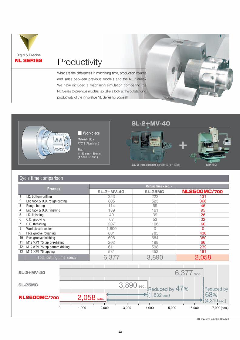
ProductivityRigid & Precise
NL SERIES
What are the differences in machining time, production volume
and sales between previous models and the NL Series?
We have included a machining simulation comparing the
NL Series to previous models, so take a look at the outstanding
productivity of the innovative NL Series for yourself.
SL-2+MV-40
+
Cycle time comparison
I.D. bottom drillingEnd face & O.D. rough cuttingRough boringEnd face & O.D. finishingI.D. finishingO.D. groovingO.D. threadingWorkpiece transferFace groove roughingFace groove finishingM12×P1.75 tap pre-drillingM12×P1.75 tap bottom drillingM12×P1.75 tapping
2538051141894967207
1,800801698202611581
2225236916139531060
785684198598452
13136646952632600
43638066239181
12345678910111213
Total cutting time <sec.> 6,377 3,890 2,058
ProcessCutting time <sec.>
SL-2+MV-40 SL-25MC NL2500MC/700
SL-2 (manufacturing period: 1978ー1987) MV-40
■ WorkpieceMaterial <JIS>:A7075 (Aluminum)
Size:A 150 mm×150 mm(A 5.9 in.×5.9 in.)
0 1,000 2,000 3,000 4,000 5,000 6,000 7,000 (sec.)
NL2500MC/700
SL-25MC
SL-2+MV-40 6,377 sec.
3,890 sec.
2,058 sec.
Reduced by 47% (1,832 sec.)
Reduced by 68% (4,319 sec.)
JIS: Japanese Industrial Standard
1st month 3rd month 6th month 9th month 1st year
SL-2+MV-40SL-25MCNL2500MC/700
2,100 3,1506,300 6,300
9,450
18,900
12,600
18,900
37,800
18,900
28,350
56,700
25,200
37,800
75,600
23
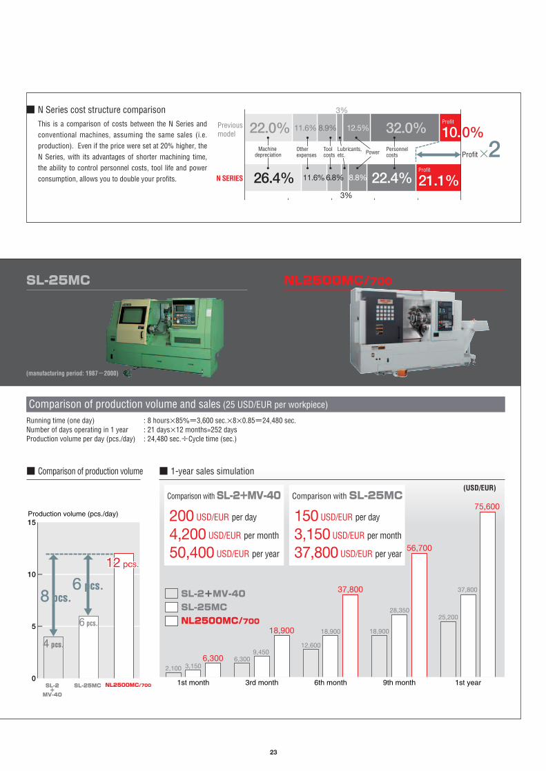
■ Comparison of production volume
Previous model
N SERIESProfit
21.1%22.4%26.4%
Profit
10.0%32.0%12.5%8.9%11.6%
6.8%11.6%
3%
8.8%
3%
22.0%
Profit M2Machine depreciation
Other expenses
Tool costs
Lubricants, etc. Power Personnel
costs
■ N Series cost structure comparisonThis is a comparison of costs between the N Series andconventional machines, assuming the same sales (i.e.production). Even if the price were set at 20% higher, theN Series, with its advantages of shorter machining time,the ability to control personnel costs, tool life and powerconsumption, allows you to double your profits.
Comparison of production volume and sales (25 USD/EUR per workpiece)
Running time (one day) : 8 hours×85%=3,600 sec.×8×0.85=24,480 sec.Number of days operating in 1 year : 21 days×12 months=252 daysProduction volume per day (pcs./day) : 24,480 sec.÷Cycle time (sec.)
SL-2+
MV-40
SL-25MC NL2500MC/700
■ 1-year sales simulation
(USD/EUR)
150 USD/EUR per day
3,150 USD/EUR per month
37,800 USD/EUR per year
200 USD/EUR per day
4,200 USD/EUR per month
50,400 USD/EUR per year
Comparison withSL-2+MV-40 Comparison withSL-25MC
(manufacturing period: 1987ー2000)
NL2500MC/700SL-25MC
0
15
10
5
Production volume (pcs./day)
4 pcs.4 pcs.
6 pcs.
12 pcs.12 pcs.
6 pcs.6 pcs.8 pcs.8 pcs.

24
Improved maintainability
MaintenanceRigid & Precise
NL SERIES
Minimizing machine down time. In our constant effort to
become the most trusted machine tool company in the
industry, we design Mori Seiki machines with maintenance
and reliability in mind.
1
2
3
With the new design, the coolant tank can be pulled out infront without having to pull out the chip conveyor. It can bepulled out easily and does not take up extra space in the back.
Pull out the coolant tank in front1
The air equipment is locatedon the right side panel in orderto facilitate maintenance.
Layout of pneumatic equipment
The oil cooler and hydraulic unit are placed together at therear of the machine without a cover for easy access.
Oil cooler, Hydraulic unit4Lubricating oil (for sliding surfaces) tank
3
The supply hole for the lubricant tank for the box way islocated in the front of the machine for easy refilling.
4
2
25
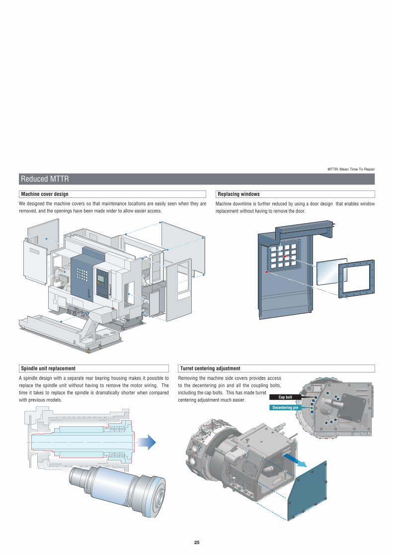
A spindle design with a separate rear bearing housing makes it possible toreplace the spindle unit without having to remove the motor wiring. Thetime it takes to replace the spindle is dramatically shorter when comparedwith previous models.
Removing the machine side covers provides accessto the decentering pin and all the coupling bolts,including the cap bolts. This has made turretcentering adjustment much easier.
Cap bolt
Decentering pin
Reduced MTTR
Spindle unit replacement
We designed the machine covers so that maintenance locations are easily seen when they areremoved, and the openings have been made wider to allow easier access.
Machine cover design
Machine downtime is further reduced by using a door design that enables windowreplacement without having to remove the door.
Replacing windows
Turret centering adjustment
MTTR: Mean Time To Repair

26
Broader field of vision
NL Series operation panel
We have changed the layout of the buttons on the operation panel to improve setup. We’ve also used rotary buttons for those with most frequent use.
Automatic door
Automatic doors to enhance automation, not only during normal operationbut also when using a robot.
X Door opening may vary from the standard machine.
ConvenienceRigid & Precise
NL SERIES
The NL Series has been designed with the operator first and
foremost in mind, with innovations included throughout the
machines to increase convenience.
Adjustable operation panel
The easy-to-use operation panel swivels 90°.Improved visibility during operation.
NL SERIES Previous model
0ー90° 0ー90°
The new design includes a vertical front door and a window closer to theoperator. The broader field of vision allows the operator to view the machineinterior without having to stoop down. The distance between the operationpanel and the machine interior has been shortened, thus reducing eye strain.
OP
OptionOP
27
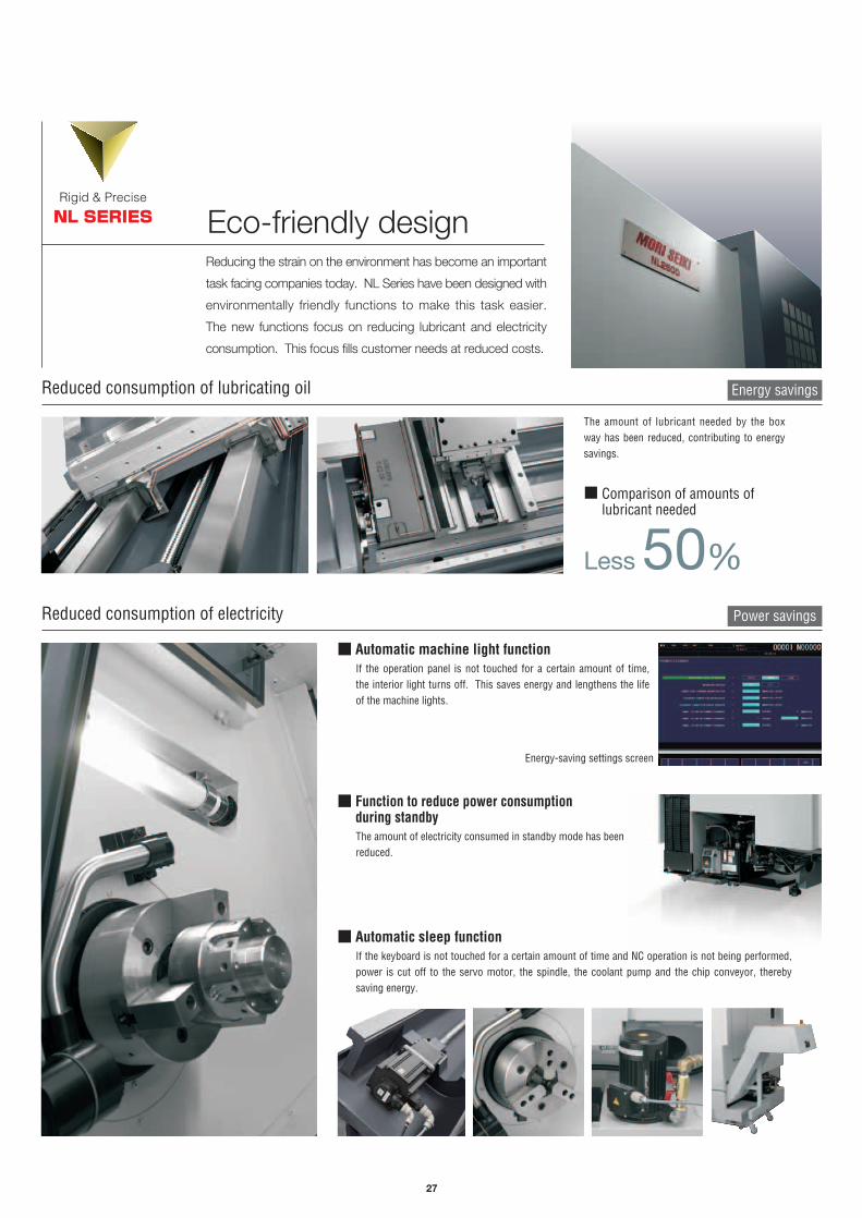
Reduced consumption of lubricating oil Energy savings
Reduced consumption of electricity Power savings
The amount of lubricant needed by the boxway has been reduced, contributing to energysavings.
■ Automatic machine light functionIf the operation panel is not touched for a certain amount of time,the interior light turns off. This saves energy and lengthens the lifeof the machine lights.
Less 50%
■ Comparison of amounts oflubricant needed
■ Function to reduce power consumption during standbyThe amount of electricity consumed in standby mode has beenreduced.
Energy-saving settings screen
Eco-friendly designRigid & Precise
NL SERIES
Reducing the strain on the environment has become an important
task facing companies today. NL Series have been designed with
environmentally friendly functions to make this task easier.
The new functions focus on reducing lubricant and electricity
consumption. This focus fills customer needs at reduced costs.
■ Automatic sleep functionIf the keyboard is not touched for a certain amount of time and NC operation is not being performed,power is cut off to the servo motor, the spindle, the coolant pump and the chip conveyor, therebysaving energy.

Loader hand
LG-05 <machine travel type> LG-10 <machine travel type>Loader type
NL1500/NL2000 NL2500 NL3000Item
Gantry-type loader Max. travel speed
ModelMax. transfer weightApplicable workpiece diameterApplicable workpiece lengthNumber of pallet tablesMax. workpiece weightMax. workpiece stacked heightApplicable workpiece diameter
180 m/min (590.6 fpm) 200 m/min (656.2 fpm)
5 kg (11 lb.)×220―150 mm (0.8―5.9 in.)10―120 mm (0.4―4.7 in.)
14 (20, 26 <please contact Mori Seiki>)35 kg (77 lb.)/pallet
20―150 mm (0.8―5.9 in.)
90 m/min (295.3 fpm)120 m/min (393.7 fpm)
10 kg (22 lb.)×2
20―150 mm (0.8―5.9 in.)10 (20 <please contact Mori Seiki>)
75 kg (165 lb.)/pallet
30―200 mm (1.2―7.8 in.)
Parallel hands (Back end hands <please contact Mori Seiki>)
470 mm (18.5 in.)
Parallel hands
30―250 mm (1.2―9.8 in.)30―200 mm (1.2―7.8 in.)
X-axis <hand up/down>Z-axis <loader unit left/right>
Workstocker
Gantry-type loader system
28
We have achieved completely automated start-to-finish machiningusing only one machine, from material supply to discharging thecompleted workpiece.This is a high-speed mass production system that reduces non-cutting time.
A ball caster wheel conveyor is used because it does not cause many chip problems.
■ Parallel hands
A close confirmation switch comes as a standard feature, thus improving the reliability of the work chucking.
Peripheral equipment
■Rotary workstocker ■ Flat workstocker<please contact Mori Seiki>
■ Belt conveyor<please contact Mori Seiki>
■ Workstocker for shaft workpieces<please contact Mori Seiki>
■ Back end hands<please contact Mori Seiki>
■Hand for shaft workpieces<please contact Mori Seiki>
Loader hand
Workstocker
NL1500/NL2000
200 m/min(656.2 fpm)
NL2500/NL3000
120 m/min(393.7 fpm)
Loader travel speed (travel)
X Depending on the shape of the workpiece, it may not be possible to machine with standard specifications. For details contact Mori Seiki.
OP
NL1500 with Gantry Loader

29
■ Others
X Gantry-type loader for shaft workpiecesX Turret-mounted workpiece-pusherX 20-station rotary workstocker/
26-station rotary workstocker (LG-05)XWorkpiece holding detector (chuck)
X External emergency stop buttonX Quality check chuteX Center-guide specifications
(workpiece pallet)X Hexagonal material specifications
(workpiece pallet)
2
Type AⅠ Type AⅡ Type AⅢ Type AⅣ
1 1 22 123 3
1 233
MachineUnits1 Workstocker2 Loader3 Turnover unit4
Type CⅠ Type CⅡ Type CⅣ Type EⅢ Type CⅢ
3
1 124
3
1 1 24
223
1 124
1 4 1 23 3
14
1 2
3
● Not applicable for hollow cylinder specifications: Type AⅠ, Type AⅢ, Type CⅠ, Type CⅢ, Type EⅢ
■ Specifications
■ Order system (please contact Mori Seiki)
Optional features <please contact Mori Seiki>
Transfer unit Turnover unit Transfer turnover unit Washing unit
Measuring system Quality inspection station
■ Others
X 14-station rotary workstocker (LG-05)/10-station rotary workstocker (LG-10)X Hand air-blowX Automatic power-off system
X Spindle orientationX Low air pressure detecting switchXWork counter
Standard features
■ System variations
Air blow system, chuck (headstock 1)
Air blow
OptionOP

30
Peripheral equipment
We have further developed the previous parts catcher so that it can nowbe customized more easily by the end user. Both spindles handleworkpieces up to double the previous length.
The capacity of the bucket has been doubledfor more convenient automation.
■Workpiece bucket
■ Recommended accessories for bar feeder specification
Bar work capacity
Operate unmanned when equipped with the workpiece conveyor.With the S-type, receive workpieces from either the No. 1 or No. 2 spindles.
Complete bar machining is possible on a single machine when coupled with a workpieceunloader. You won’t need a work loader/unloader or turnover unit.
● Bar work capacity: depending on the chuck/cylinder used and its restrictions, it may not be possible to reach full bar work capacity.
*Standard for S, SMC and SY types. (Not including gantry loader specifications)
X Bar feeder XMulti counter XSignal tower X Guide bushingXWork stopper
NL1500
φ52 mm(φ2.0 in.)
NL2000
φ65 mm(φ2.5 in.)
NL2500
φ80 mm(φ3.1 in.)
NL3000
φ90 mm(φ3.5 in.)
■ Applicable workpiece diameterNL SERIES
80 mm (3.1 in.)■ Applicable workpiece lengthNL SERIES
200 mm (7.8 in.)
■ Max. transfer weightNL1500/NL2000/NL2500
3.0 kg (6.6 lb.)
NL3000
4.0 kg (8.8 lb.)
Automatically discharge the machined piece from the No. 2 spindle, making it easierto automate machining of bar workpieces and making this system ideal for longworkpieces that cannot be handled by a workpiece unloader.
Bar feeder Bar puller
Bar feederNL2000
Workpiece bucket
In-machine traveling workpiece unloader
Workpiece conveyor
Workpiece unloader* (built-in type)
Bar feeder system
Bar puller systemIn-machine traveling workpiece unloader system
OP
OP
OPOP
31
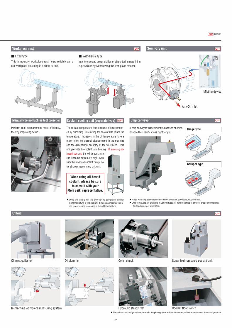
Hinge type
X Hinge type chip conveyor comes standard on NL3000/2000, NL3000/3000.
X Chip conveyors are available in various types for handling chips of different shape and material.
For details contact Mori Seiki.
Scraper type
Perform tool measurement more efficiently,thereby improving setup.
This temporary workpiece rest helps reliably carryout workpiece chucking in a short period.
Interference and accumulation of chips during machiningis prevented by withdrawing the workpiece retainer.
Collet chuckOil mist collector Oil skimmer
In-machine workpiece measuring system Coolant float switchHydraulic steady rest
Super high-pressure coolant unit
A chip conveyor that efficiently disposes of chips.Choose the specifications right for you.
Workpiece rest Semi-dry unit
Coolant cooling unit (separate type)
Others
Manual type in-machine tool presetter Chip conveyor
■ Fixed type ■ Withdrawal type
Misting device
Air+Oil mist
The coolant temperature rises because of heat generat-ed by machining. Circulating the coolant also raises thetemperature. Increases in the oil temperature have amajor effect on thermal displacement in the machineand the dimensional accuracy of the workpiece. Thisunit prevents the coolant from heating. When using oil-based coolant, the oil temperaturecan become extremely high evenwith the standard coolant pump, sowe strongly recommend this unit.
When using oil-basedcoolant, please be sure
to consult with yourMori Seiki representative.
● While this unit is not the only way to completely control
the temperature of the coolant, it makes a major contribu-
tion to preventing increases in the oil temperature.
OP OP
OP OP
OP
X The colors and configurations shown in the photographs or illustrations may differ from those of the actual product.
OptionOP

32
* Programs can be transferred between the user memory area and an external device such as an NC memory, an RS-232-C connection, a card interface or the MORI-SERVER.
Programs that call sub-programs stored in the user memory area using M98/G65 must be stored in the NC memory.● Card DNC operation transfer speed: the maximum feed speed is 7 m/min for a program with 25-character blocks at a pitch of 1 mm.
(These are not absolute values, and feedrate may occasionally deteriorate)
● Please see the product catalog for details. ● The photo shown may differ from actual machine.
MAPPS: Mori Advanced Programming Production System
A New High-Performance Operating System
for CNC Lathes
Improved hardware specs
50 MB<tape memory length equivalent to
127,000 m (416,687 ft)>
Standard
500 MB OP
■ Card DNC operation● Select the program needed from within the user memory area and
use it for DNC operation for the NC unit.(Macro programs such as GOTO, IF and WHILE cannot be used in DNC operating programs)
● Programs in the user memory area can be edited, copied, deletedand renamed.(Programs up to 10 MB can be edited on the spot)
■ Equipped with a USB interface● Data can be transferred easily between the machine and your PC.
(For the USB memory, please use Mori Seiki specified products. We cannot guarantee correct operations with other peripheral equipment such as USB hard disks)
■ A large MAPPS user memory area*
● We have prepared an area which is separate from the NC memory,where programs can be stored in MAPPS.
A handy calculator function
Network
A calculator key is included, allowing theoperator to call up a function calculatorfrom any screen.
■ MORI-SERVER Standard feature
A network-enabled data management system for high-speed transfer ofdata between computer and machine.
■ MORI-NET Global EditionMori Seiki’s MORI-NET Global Edition is a customer support serviceusing the Internet.
The CPU’s processing power has been improved, with many functions which dramatically
reduce the time for programming and setup. The 3rd generation NC unit MAPPSⅢ is
designed for productivity. A new interface connecting person and machine.
10.4-inch operation panel
OP
33
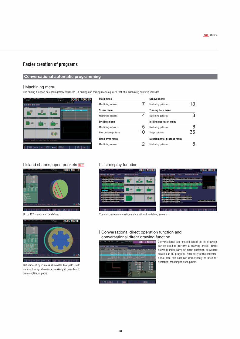
Drilling menu
Machining patterns 5Hole position patterns 10
Groove menu
Machining patterns 13Screw menu
Machining patterns 4Turning hole menu
Machining patterns 3
■ List display function
You can create conversational data without switching screens.
Milling operation menu
Machining patterns 6Shape patterns 35
Main menu
Machining patterns 7
Hand-over menu
Machining patterns 2Supplemental process menu
Machining patterns 8
Conversational data entered based on the drawingscan be used to perform a drawing check (directdrawing) and to carry out direct operation, all without creating an NC program. After entry of the conversa-tional data, the data can immediately be used foroperation, reducing the setup time.
OptionOP
Faster creation of programs
Conversational automatic programming
■ Machining menuThe milling function has been greatly enhanced. A drilling and milling menu equal to that of a machining center is included.
OP■ Island shapes, open pockets
Up to 127 islands can be defined.
Definition of open areas eliminates tool paths withno machining allowance, making it possible to create optimum paths.
■ Conversational direct operation function andconversational direct drawing function

34
登録 挿入
for CNC Lathes
A New High-Performance Operating System
● Search ● Replace ● Top ● End ● Select ●Copy ● Cut ● Paste● Insert row ● Insert sequence No. ● Edit two programs simultaneously (background editing)
● Displays line number being edited● Edited line numbers are displayed in red● Actions can be undone any number of times (up to 400 kB)● Batch replaces can also be undone or redone in a single step
Register Insert
Faster creation of programs
Creating programs G code editing function
Program editing function
1
■ Extended editingA large number of sub-menus is available.
■ Rapid registrationFull programs and portions of programs that are used frequently can be registeredand later pasted into other programs with a single operation.
■ Editing line number display, Undo/Redo functionThis allows for mistakes to be corrected when creating a program.
■ HelpWhen you get stuck, the G code guidance and PLC message details function areuseful.
Comparison of editing timesWe made a comparison of thetime needed to copy, cut andpaste 100 blocks, 1 block 5-wordprogram.
Previous model
MAPPSⅢ
7.5 sec. 11 sec.
Copy Cut
1.5 sec. 2.5 sec.
Copy buffer
Previous model: 4 kBMAPPSⅢ : 10 kB
① Program② Coordinate display③ Tool info
②
① ③
Program check2
■ Simultaneous 3-way split displayThree different screens can be displayed at once.The screens can be switched easily using the soft keys.
■ Synchronized drawing
Simulations which are synchronized with actual machining can be made in theprogram check screen.
Program management3
■ Group management
Programs can be managed ingroups for easier searching.
■ SortingData can be sorted according to different criteria.
■ Status displayThe status of the program -No Editing, Foreground andBackground - is displayed.
■ Custom displayChoose which information you want displayed.
● By number ● By size ● By comment
● Size ● Comment ● Display/hide group
35
OptionOP
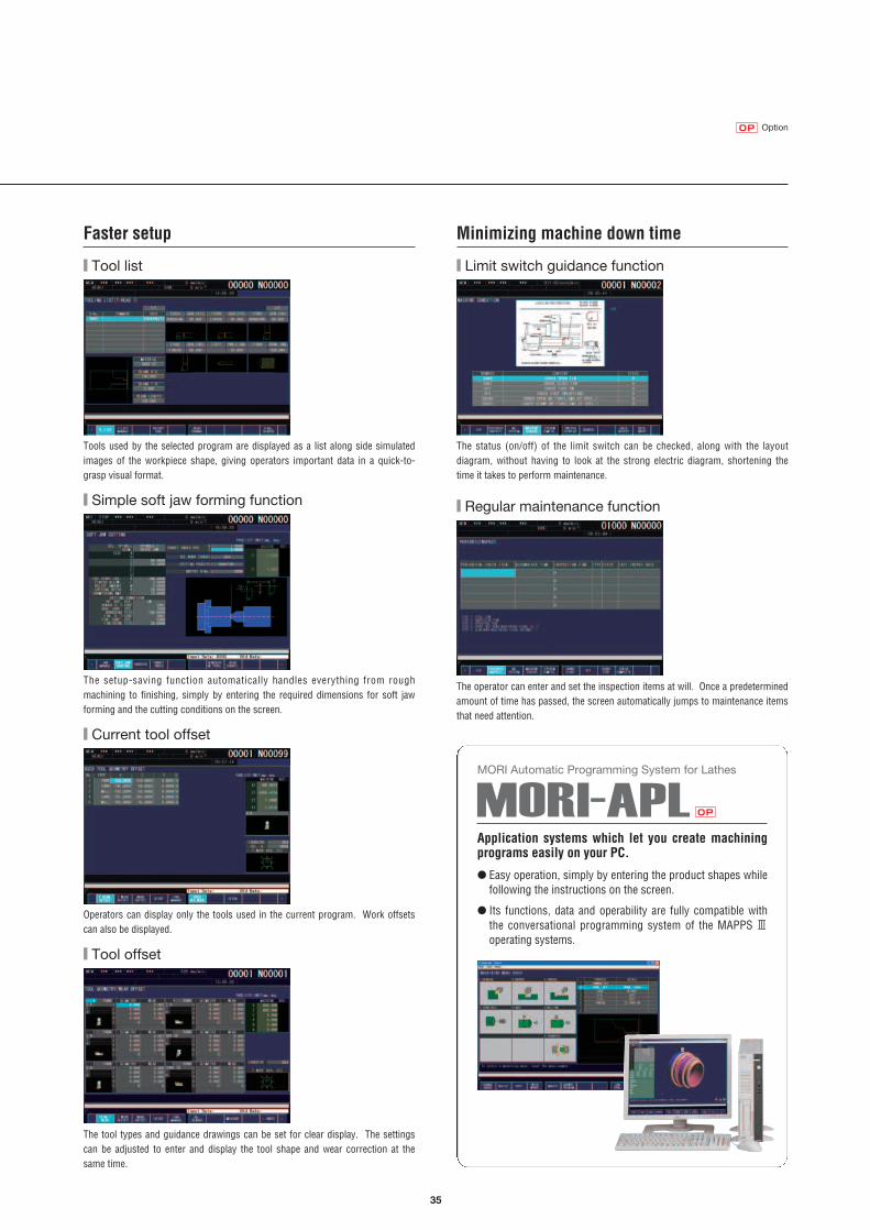
Faster setup
■ Tool list
Tools used by the selected program are displayed as a list along side simulatedimages of the workpiece shape, giving operators important data in a quick-to-grasp visual format.
■ Simple soft jaw forming function
The setup-saving function automatically handles everything from rough machining to finishing, simply by entering the required dimensions for soft jawforming and the cutting conditions on the screen.
■ Current tool offset
Operators can display only the tools used in the current program. Work offsetscan also be displayed.
■ Tool offset
The tool types and guidance drawings can be set for clear display. The settingscan be adjusted to enter and display the tool shape and wear correction at thesame time.
Minimizing machine down time
■ Limit switch guidance function
The status (on/off) of the limit switch can be checked, along with the layout diagram, without having to look at the strong electric diagram, shortening thetime it takes to perform maintenance.
■ Regular maintenance function
The operator can enter and set the inspection items at will. Once a predeterminedamount of time has passed, the screen automatically jumps to maintenance itemsthat need attention.
Application systems which let you create machiningprograms easily on your PC.
● Easy operation, simply by entering the product shapes whilefollowing the instructions on the screen.
● Its functions, data and operability are fully compatible withthe conversational programming system of the MAPPS Ⅲoperating systems.
MORI Automatic Programming System for Lathes
OP

36
System examples
Total support for construction of a high-productivity system.More than half of the machines delivered by Mori Seiki are at least partially customized. The Engineering Department approaches such custom-specificationmachines under the motto of “There are as many optimized machine solutions asthere are workpieces,” working to create systems that bring the most advantages toyour unique production needs (turnkey systems). Mori Seiki delivers total solutions by selecting the best line process that matches your future outlook, fromsimple design specifications to large projects covering entire production plants.
Turnkey systems
VL-25+NH5000Robot specifications
FM-303Flexible Transfer Line(9 unit series)
SuperMILLER 400Robot specifications
ULTIMILL V3000+CL1500Gantry-type loader system

37
Fixture examples
Example of special chucks
Sample workpieces
Outside chucking/inside chucking type Outside chucking type Inside chucking type Center compensating type
For flange workpieces For shaft workpieces

38
JapanJapan
JakartaJakartaJakarta
MelbourneMelbourneSydneySydney
TaipeiTaipeiTaipei
SeoulSeoulSeoul
Hong KongHong Kong
BeijingBeijing
BangkokBangkokBangkok
Kuala LumpurKuala LumpurKuala Lumpur
ShenzhenShenzhenChongqingChongqingChongqing
GuangzhouGuangzhouGuangzhou
TianjinTianjin
LondonLondon
BirminghamBirmingham
ShanghaiShanghaiShanghai
HamburgHamburg
BarcelonaBarcelonaBarcelona
MilanMilanMilan
DIXI MachinesDIXI Machines(Switzerland) (Switzerland) DIXI Machines(Switzerland)
IstanbulIstanbul
MunichMunichPraguePrague
Munich
Sãn Paolon PaoloSãn Paolo
CharlotteCharlotte
New JerseyNew Jersey
BostonBoston
CincinnatiCincinnatiMexico CityMexico CityMexico City
San FranciscoSan FranciscoLos AngelesLos Angeles
DetroitDetroit
ChicagoChicagoChicagoStuttgartStuttgart
SingaporeSingapore
DallasDallas
New DelhiNew DelhiNew Delhi
DalianDalian
LyonLyon
Prague
ToulouseToulouse
ParisParisDusseldorfDusseldorfDusseldorf
MoscowMoscowMoscow
SuzhouSuzhouSuzhou
SacramentoSacramentoWuhanWuhan
Iga Campus
Dallas Technical Center
Stuttgart Technical Center
Singapore Technical Center
Shanghai Parts Center
46
Overseas distributors
143
● Overseas subsidiaries● Overseas offices▲ Overseas distributors□ Parts Centers
Parts locationsOverseas countries
World-Standard Quality & High-Reliability NetworkMori Seiki is a leading manufacturer of NC machine tools with asolid worldwide reputation and years of international experience.There are Mori Seiki bases in major cities on every continent,and all of them function as Technical and Service Centers whichwork closely with our customers. Our expert staff is alwaysready to help you. Constantly updated computer records allowus to find customer details immediately and give prompt inter-national service.
Service network
Mori Seiki’s global service
Service Center (Iga, Chiba)
Parts Center
Service Personnel
24 hours
24Shipped within 24 hours
24Delivered within 24 hours
365 Operating 365days a year
Service systems
Parts Center at the Stuttgart Technical Center.
At the Iga and Chiba Service Centers, wehave the following systems to respond toinquiries from overseas Technical Centers.

39
Meticulous follow-up byexperienced engineers.
Accumulation of operating status data
InternetAt your office and home
Server
At your factory
Remote monitoring of your machines over the Internet. With this service it is possible to build remote management systems for machine tools having great speed and cost performance.
●This system allows you to see the operating status ofyour machine tools over the Internet from whereveryou may be in the world.
●Regular e-mail notifications are sent to you directlywith your machine operating status.
Low initial investment and running cost
Technical seminars coveringprogramming, maintenance,etc.
Parts supply
Training Applications
MORI-NET Global Edition
Service
OptionOP
OP
We have extensive parts bases in Iga, Dallas, Stuttgart, Singapore and Shanghai.
Proposals for upgrading systems andhigh-efficiency machining.

40
Hydraulic chuck (headstock 1)
Hydraulic chuck (headstock 2)
Hydraulic steady rest (SLU-1Z)Hydraulic steady rest (SLUA-1Z)Hydraulic steady rest (SLU-2Z)Hydraulic steady rest (SLUA-2Z)Hydraulic steady restSteady rest
6 inches8 inches10 inches6 inches8 inchesBolt-tighteningBolt-tighteningBolt-tighteningBolt-tighteningInterfaceBolt-tightening
Tailstock spindle live center*1
Tailstock spindle built-in center*2
Drilling with the tailstock <only applicable for live center specification>
No tailstockHeadstock 2 tailstock
MT-4MT-3
Standard & optional features (NL1500/NL2000)
Spindle
Turret
Workpiece holding device
Tailstock/tailstock spindle
Measurement
Improved accuracy
NL1500 NL2000
2-axisturning MC Y S SMC SY 2-axis
turning MC Y S SMC SY
●
○
○
×
×
×
×
×
●
○
○
×
×
×
×
×
●
○
○
×
×
●
○
×
●
○
○
×
×
×
×
×
●
○
○
×
×
●
○
×
●
○
○
×
×
●
○
×
×
×
×
●
○
×
×
×
×
×
×
●
○
×
×
×
×
×
×
●
○
●
×
○
×
×
×
●
○
×
×
×
×
×
×
●
○
●
×
○
×
×
×
●
○
●
×
○
●
×
○
×
○
○
×
○
×
×
●
●
○
○
●
○
●
×
○
×
○
○
×
○
○
×
×
●
×
○
×
×
○
○
×
×
×
○
○
○
○
○
○
○
○
×
×
×
○
○
○
○
○
○
●
○
○
○
×
●
○
○
○
×
Manual type in-machine tool presetter (headstock 1)Manual type in-machine tool presetter (headstock 2)Automatic in-machine tool presetter (headstock 1)
In-machine workpiece measuring system (inner and outer diameter measurement) <certain workpiece shapes cannot be measured>
In-machine workpiece measuring system
Pivoting typeRemovablePivoting type
Headstock 2
●
×
○
○
×
●
×
○
○
×
Direct scale feedbackX-axisY-axisZ-axis
○
×
○
○
×
○
Coolant
Through-spindle coolant systemHeadstock 1Headstock 2
☆
×
☆
×
●
●
○
○
○
●
×
○
○
×
○
×
○
○
○
○
☆
☆
☆
×
●
●
○
○
○
●
●
○
○
○
○
○
○
○
×
○
☆
☆
☆
☆
●
×
○
○
×
●
×
○
○
×
○
×
○
○
×
○
☆
×
☆
×
●
●
○
○
○
●
×
○
○
×
○
×
○
○
○
○
☆
☆
☆
×
●
●
○
○
○
●
●
○
○
○
○
○
○
○
×
○
☆
☆
☆
☆
×
×
×
×
○
●
○
○
○
×
×
×
×
×
○
×
×
×
×
○
●
○
○
○
×
●
○
○
○
×
×
×
×
×
○
●
○
○
○
×
×
×
×
×
○
×
×
×
×
○
○
○
×
○
○
×
×
×
×
×
×
○
○
×
×
×
○
○
○
○
○
○
○
○
×
○
○
×
×
×
×
×
×
○
○
×
○
○
×
×
×
×
×
×
×
○
○
×
×
○
○
○
○
○
○
×
○
○
×
×
○
○
○
○
○
○
×
○
○
○
○
×
×
×
×
×
×
×
○
○
×
×
○
○
○
○
○
○
×
○
○
○
○
×
×
×
×
×
×
×
○
○
○
○
×
×
×
×
×
×
●
×
○
×
○
○
×
○
×
×
×
●
×
○
×
×
●
×
○
×
○
○
×
○
×
×
●
●
○
○
●
○
●
×
○
×
○
○
×
○
×
×
●
●
○
○
●
○
●
×
○
×
○
○
×
○
×
×
●
●
○
○
●
○
●
○
○
○
○
○
○
○
×
×
●
●
○
○
●
○
●
○
○
○
○
○
○
○
○
○
×
●
×
○
×
×
●
○
○
○
○
○
○
○
×
○*2
×
●
×
○
×
×
●
○
○
○
○
○
○
○
×
×
●
●
○
○
●
○
●
○
○
○
○
○
○
○
×
×
●
●
○
○
●
○
●
○
○
○
○
○
○
○
×
×
●
●
○
○
●
○
12-station turret head, bolt-tightened10-station turret head, bolt-tightened12-station turret head, bolt-tightened10-station turret head, bolt-tightened20-station turret head, bolt-tightened12-station turret head, quick-change VDI10-station turret head, quick-change VDI16-station turret head, quick-change VDI12-station turret head, quick-change VDI10-station turret head, quick-change VDI
Max. rotary tool spindle speed
Tool holdersRotary tool holdersCapto-compatible holder
Overhang of O.D. cutting rotary tool
6,000 min-1: 11/11/7.5 kW (15/15/10 HP) <50%ED/30 min/cont>6,000 min-1: 15/15/11 kW (20/20/15 HP) <50%ED/30 min/cont>8,000 min-1: 11/7.5 kW (15/10 HP) <25%ED/cont>*
5,000 min-1: 15/15/11 kW (20/20/15 HP) <50%ED/30 min/cont>5,000 min-1: 18.5/18.5/18.5/15 kW (24.7/24.7/24.7/20 HP)
<25%ED/50%ED/30 min/cont>6,000 min-1: 11/7.5 kW (15/10 HP) <25%ED/cont>
8,000 min-1: 11/7.5 kW (15/10 HP) <25%ED/cont>{headstock 1 side is also 8,000 min-1}
5,000 min-1: 11/7.5 kW (15/10 HP) <25%ED/cont>
SL compatibleSL compatibleNZ compatibleIncluding outer circumferenceIncluding outer circumferenceIncluding outer circumference*1
Face typeFace type
6,000 min-1: 5.5/5.5/3.7 kW (7.5/7.5/5 HP)<3 min/5 min/cont>
50 mm (2.0 in.)
100 mm (3.9 in.)*3<Y-axis travel is limited for the Y and SY types>
Headstock 1
Headstock 2
*1 Tools used: A 30 mm (A 1.2 in.) VDI holder (for ZT1000Y). *2 Headstock 1 only. *3 Does not apply when using 20-station turret specifications.
*Through-spindle hole diameter: 43 mm (1.7 in.).
*1 The center is optional. *2 The center is standard.
41
NL1500 NL2000
2-axisturning MC Y S SMC SY 2-axis
turning MC Y S SMC SY
○
○
○
○
○
○
○
×
×
○
☆
○
○
○
○
○
○
○
○
○
○
○
○
×
×
○
☆
○
○
○
○
○
LG-0514 stations20 stations26 stations
In-machine traveling type
Cylinder typeInterfaceInterfaceInterface
A 53 mm (A 2.0 in.)⦆
Gantry-type loader
Workstocker
Workpiece unloader
Workpiece conveyor
Workpiece push-out equipment (headstock 2)
LoaderRobotBar feederWorkpiece restPull-out fingerTurret-mounted workpiece-pusherGuide bushing
×
○
○
×
○
○
○
○
○
○
●*1
○
○
●
☆
○
☆
○
○
○
○
○
○
○
○
○
○
○
○
×
×
○
☆
○
○
○
○
○
●
○
○
×
○
○
○
○
○
○
●*1
○
○
●
☆
○
☆
○
○
○
○
○
○
○
○
○
●*1
○
○
●
☆
○
☆
○
○
○
○
○
●
○
○
●
○
○
○
○
○
○
○
○
○
×
×
○
☆
○
○
○
○
○
○
○
○
○
○
○
○
×
×
○
☆
○
○
○
○
○
×
○
○
×
○
○
○
○
○
○
●*1
○
○
●
○*2
○
☆
○
○
○
○
○
○
○
○
○
○
○
○
×
×
○
☆
○
○
○
○
○
●
○
○
×
○
○
○
○
○
○
●*1
○
○
●
○*2
○
☆
○
○
○
○
○
○
○
○
○
●*1
○
○
●
○*2
○
☆
○
○
○
○
○
●
○
○
●
○
○100 mm (3.9 in.)
Low air pressure detecting switchDry anchor
Raised machine height <not applicable when the right disposal type chip conveyor is selected>
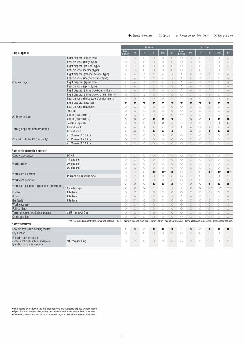
●: Standard features ○: Option ☆: Please contact Mori Seiki ×: Not available
Chip disposal
Automatic operation support
Safety features
○
○
○
○
☆
☆
☆
☆
☆
○
☆
●
○
○
○
●
×
☆
●
○
○
○
○
○
○
○
☆
☆
☆
☆
☆
○
☆
●
○
○
○
×
○
☆
×
○
○
○
○
○
○
○
☆
☆
☆
☆
☆
○
☆
●
○
○
○
●
×
☆
●
○
○
○
○
○
○
○
☆
☆
☆
☆
☆
○
☆
●
○
○
○
●
×
☆
●
○
○
○
○
○
○
○
☆
☆
☆
☆
☆
○
☆
●
○
○
○
×
○
☆
×
○
○
○
○
○
○
○
☆
☆
☆
☆
☆
○
☆
●
○
○
○
×
○
☆
×
○
○
○
○
○
○
○
☆
☆
☆
☆
☆
○
☆
●
○
○
○
●
×
☆
●
○
○
○
○
○
○
○
☆
☆
☆
☆
☆
○
☆
●
○
○
○
×
○
☆
×
○
○
○
○
○
○
○
☆
☆
☆
☆
☆
○
☆
●
○
○
○
●
×
☆
●
○
○
○
○
○
○
○
☆
☆
☆
☆
☆
○
☆
●
○
○
○
●
×
☆
●
○
○
○
○
○
○
○
☆
☆
☆
☆
☆
○
☆
●
○
○
○
×
○
☆
×
○
○
○
○
○
○
○
☆
☆
☆
☆
☆
○
☆
●
○
○
○
×
○
☆
×
○
○
○
Right disposal (hinge type)Rear disposal (hinge type)Right disposal (scraper type)Rear disposal (scraper type)Right disposal (magnet scraper type)Rear disposal (magnet scraper type)Right disposal (spiral type)Rear disposal (spiral type)Right disposal (hinge type+drum filter)Right disposal (hinge type <for aluminum>)Rear disposal (hinge type <for aluminum>)Right disposal (interface)Rear disposal (interface)Tool tipChuck (headstock 1)Chuck (headstock 2)Tailstock spindleHeadstock 1Headstock 2A 100 mm (A 3.9 in.)A 125 mm (A 4.9 in.)A 150 mm (A 5.9 in.)
Chip conveyor
Air blow system
Through-spindle air blow system
Oil mist collector I/F (duct only)
*1 Not including gantry loader specifications. *2 For spindle through hole dia. 73 mm (2.9 in.) specifications only. Consultation is required for other specifications.
●The details given above and the specifications are subject to change without notice.●Specifications, accessories, safety device and function are available upon request.●Some options are not available in particular regions. For details contact Mori Seiki.

42
Spindle
Turret
Workpiece holding device
Tailstock/tailstock spindle
Measurement
NL2500/700 NL2500/1250
2-axisturning
2-axisturning SMC MC SMCY Y SYS SMC SY
●
○
×
×
●
○
×
×
●
○
×
×
●
○
●
○
●
○
×
×
●
○
×
×
●
○
●
○
●
○
●
○
●
○
●
○
●
○
×
×
●
○
●
○
●
○
●
○
Standard & optional features (NL2500)
Headstock 1
Headstock 2
4,000 min-1: 18.5/18.5/15 kW (24.7/24.7/20 HP) <25%ED/50%ED/cont>4,000 min-1: 26/26/22 kW (34.7/34.7/30 HP) <10 min/30 min/cont>6,000 min-1: 11/7.5 kW (15/10 HP) <25%ED/cont>5,000 min-1: 11/7.5 kW (15/10 HP) <25%ED/cont>
●
○
○
○
○
○
×
×
●
●
○
○
●
○
●
○
○
○
○
○
○
○
×
●
×
○
×
×
●
○
○
○
○
○
×
×
●
●
○
○
●
○
●
○
○
○
○
○
×
×
●
●
○
○
●
○
●
○
○
○
○
○
○
○
×
●
×
○
×
×
●
○
○
○
○
○
×
×
●
●
○
○
●
○
●
○
○
○
○
○
×
×
●
●
○
○
●
○
●
○
○
○
○
○
×
○
×
●
×
○
×
×
●
○
○
○
○
○
×
×
●
●
○
○
●
○
●
○
○
○
○
○
×
×
●
●
○
○
●
○
●
○
○
○
○
○
×
○
×
●
×
○
×
×
●
○
○
○
○
○
×
×
●
●
○
○
●
○
12-station turret head, bolt-tightened10-station turret head, bolt-tightened12-station turret head, bolt-tightened10-station turret head, bolt-tightened12-station turret head, quick-change VDI10-station turret head, quick-change VDI12-station turret head, quick-change VDI10-station turret head, quick-change VDI
Max. rotary tool spindle speed
Tool holdersRotary tool holdersCapto-compatible holder
Overhang of O.D. cutting rotary tool
SL compatibleSL compatibleIncluding outer circumferenceIncluding outer circumferenceFace typeFace type
6,000 min-1: 5.5/5.5/3.7 kW (7.5/7.5/5 HP)<3 min/5 min/cont>
50 mm (2.0 in.)
100 mm (3.9 in.) <Y-axis travel is limited for the Y and SY types>
○
○
×
×
○
×
○
×
○
×
○
×
×
×
×
×
○
○
○
○
×
×
○
×
○
×
○
×
○
×
×
×
×
×
○
○
○
○
×
×
○
×
○
×
○
×
○
×
×
×
×
×
○
○
○
○
○
○
×
×
×
×
×
×
×
×
×
×
×
×
×
×
○
○
×
×
○
○
○
○
○
○
○
○
○
○
○
○
○
○
○
○
×
×
○
○
○
○
○
○
○
○
○
○
○
○
○
○
○
○
○
○
×
×
×
×
×
×
×
×
×
×
×
×
×
×
○
○
○
○
×
×
×
×
×
×
×
×
×
×
×
×
×
×
○
○
○
○
×
×
×
×
×
×
×
×
×
×
×
×
×
×
○
○
×
×
○
○
○
○
○
○
○
○
○
○
○
○
○
○
○
○
○
○
×
×
×
×
×
×
×
×
×
×
×
×
×
×
○
○
○
○
×
×
×
×
×
×
×
×
×
×
×
×
×
×
Hydraulic chuck (headstock 1)
Hydraulic chuck (headstock 2)
Hydraulic steady rest (SLU-1Z)
Hydraulic steady rest (SLUA-1Z)
Hydraulic steady rest (SLU-2Z)
Hydraulic steady rest (SLUA-2Z)
Hydraulic steady rest (SLU-B3Z)
Hydraulic steady rest (SLUA-B3Z)
Hydraulic steady restSteady rest
10 inches12 inches6 inches8 inchesBolt-tighteningCarriage direct-coupled (suspended from the saddle)Bolt-tighteningCarriage direct-coupled (suspended from the saddle)Bolt-tighteningCarriage direct-coupled (suspended from the saddle)Bolt-tighteningCarriage direct-coupled (suspended from the saddle)Bolt-tighteningCarriage direct-coupled (suspended from the saddle)Bolt-tighteningCarriage direct-coupled (suspended from the saddle)InterfaceBolt-tightening
●
○
○
○
○
×
●
○
○
○
○
×
●
○
○
○
○
×
×
×
×
×
×
○
●
×
○
○
○
×
●
×
○
○
○
×
×
×
×
×
×
○
×
×
×
×
×
○
×
×
×
×
×
○
●
×
○
○
○
×
×
×
×
×
×
○
×
×
×
×
×
○
Tailstock spindle live center*1
Tailstock spindle built-in center*2
Drilling with the tailstock <only applicable for live center specification>
No tailstockHeadstock 2 tailstock
MT-5MT-3MT-4
●
×
○
○
×
●
×
○
○
×
●
×
○
○
×
●
●
○
○
○
●
×
○
○
×
●
×
○
○
×
●
●
○
○
○
●
●
○
○
○
●
●
○
○
○
●
×
○
○
×
●
●
○
○
○
●
●
○
○
○
Manual type in-machine tool presetter (headstock 1)Manual type in-machine tool presetter (headstock 2)Automatic in-machine tool presetter (headstock 1)
In-machine workpiece measuring system (inner and outer diameter measurement) <certain workpiece shapes cannot be measured>
In-machine workpiece measuring system
Pivoting typeRemovablePivoting type
Headstock 2
*1 The center is optional. *2 The center is standard.

43
NL2500/700 NL2500/1250
2-axisturning
2-axisturning SMC MC SMCY Y SYS SMC SY
●: Standard features ○: Option ☆: Please contact Mori Seiki ×: Not available
Chip disposal
Automatic operation support
Safety features
○
○
○
○
☆
☆
☆
☆
☆
○
☆
●
○
○
○
×
○
☆
×
○
○
○
○
○
○
○
☆
☆
☆
☆
☆
○
☆
●
○
○
○
×
○
☆
×
○
○
○
○
○
○
○
☆
☆
☆
☆
☆
○
☆
●
○
○
○
×
○
☆
×
○
○
○
○
○
○
○
☆
☆
☆
☆
☆
○
☆
●
○
○
○
●
×
☆
●
○
○
○
○
×
○
×
☆
×
☆
×
☆
○
×
●
×
○
○
×
○
☆
×
○
○
○
○
×
○
×
☆
×
☆
×
☆
○
×
●
×
○
○
×
○
☆
×
○
○
○
○
×
○
×
☆
×
☆
×
☆
○
×
●
×
○
○
●
×
☆
●
○
○
○
○
○
○
○
☆
☆
☆
☆
☆
○
☆
●
○
○
○
●
×
☆
●
○
○
○
○
○
○
○
☆
☆
☆
☆
☆
○
☆
●
○
○
○
●
×
☆
●
○
○
○
○
×
○
×
☆
×
☆
×
☆
○
×
●
×
○
○
×
○
☆
×
○
○
○
○
×
○
×
☆
×
☆
×
☆
○
×
●
×
○
○
●
×
☆
●
○
○
○
○
×
○
×
☆
×
☆
×
☆
○
×
●
×
○
○
●
×
☆
●
○
○
○
Chip conveyor
Air blow system
Through-spindle air blow system
Oil mist collector I/F (duct only)
Right disposal (hinge type)Rear disposal (hinge type)Right disposal (scraper type)Rear disposal (scraper type)Right disposal (magnet scraper type)Rear disposal (magnet scraper type)Right disposal (spiral type)Rear disposal (spiral type)Right disposal (hinge type+drum filter)Right disposal (hinge type <for aluminum>)Rear disposal (hinge type <for aluminum>)Right disposal (interface)Rear disposal (interface)Tool tipChuck (headstock 1)Chuck (headstock 2)Tailstock spindleHeadstock 1Headstock 2A 100 mm (A 3.9 in.)A 125 mm (A 4.9 in.)A 150 mm (A 5.9 in.)
○
○
○
○
○
○
×
×
○
☆
○
○
○
○
○
○
○
○
○
○
○
×
×
○
☆
○
○
○
○
○
○
○
○
○
○
○
×
×
○
☆
○
○
○
○
○
○
○
○
●*
○
○
●
○
○
☆
○
○
○
○
○
○
○
○
○
×
☆
×
×
○
☆
○
○
○
○
○
○
○
○
○
×
☆
×
×
○
☆
○
○
○
○
○
○
○
○
●*
×
☆
●
○
○
☆
○
○
○
○
○
○
○
○
●*
○
○
●
○
○
☆
○
○
○
○
○
○
○
○
●*
○
○
●
○
○
☆
○
○
○
○
○
○
○
○
○
×
☆
×
×
○
☆
○
○
○
○
○
○
○
○
●*
×
☆
●
○
○
☆
○
○
○
○
○
○
○
○
●*
×
☆
●
○
○
☆
○
○
○
○
○
Gantry-type loader
Workstocker
Workpiece unloader
Workpiece conveyor
Workpiece push-out equipment
LoaderRobotBar feederWorkpiece restPull-out fingerTurret-mounted workpiece-pusherGuide bushing
LG-1010 stations20 stations
In-machine traveling type
Cylinder typeInterfaceInterfaceInterface
A 53 mm (A 2.0 in.)⦆
×
○
○
×
○
○
×
○
○
●
○
○
×
○
○
×
○
○
●
○
○
●
○
○
●
○
○
×
○
○
●
○
○
●
○
○
Low air pressure detecting switchDry anchor
Raised machine height <not applicable when the right disposal type chip conveyor is selected>
100 mm (3.9 in.)
* Not including gantry loader specifications.
Improved accuracy
Coolant
○
×
○
○
×
○
○
○
○
○
×
○
○
×
○
○
○
○
○
×
○
○
×
○
○
○
○
○
×
○
○
×
○
○
○
○
Direct scale feedbackX-axisY-axisZ-axis
☆
×
☆
×
☆
×
☆
☆
☆
×
☆
×
☆
☆
☆
☆
☆
☆
☆
×
☆
☆
☆
☆Through-spindle coolant system
Headstock 1Headstock 2
●The details given above and the specifications are subject to change without notice.●Specifications, accessories, safety device and function are available upon request.●Some options are not available in particular regions. For details contact Mori Seiki.

44
Spindle
Turret
Workpiece holding device
Tailstock/tailstock spindle
Measurement
NL3000/700 NL3000/1250 NL3000/2000 NL3000/3000
2-axisturning
2-axisturning
2-axisturningMC MC MCY Y Y2-axis
turningMC Y
●
○
●
○
●
○
●
○
●
○
●
○
●
○
●
○
●
○
●
○
●
○
●
○
Standard & optional features (NL3000)
Spindle3,000 min-1: 22/18.5 kW (30/24.7 HP) <30 min/cont>3,000 min-1: 30/25 kW (40/33.3 HP) <30 min/cont>
○
●
○
○
○
○
×
●
●
○
○
●
○
○
●
○
○
○
○
○
×
●
×
○
×
×
○
●
○
○
○
○
×
●
●
○
○
●
○
○
●
○
○
○
○
×
●
●
○
○
●
○
○
●
○
○
○
○
○
×
●
×
○
×
×
○
●
○
○
○
○
×
●
●
○
○
●
×
○
●
○
○
○
○
×
●
●
○
○
●
×
○
●
○
○
○
○
○
×
●
×
○
×
×
○
●
○
○
○
○
×
●
●
○
○
●
○
○
●
○
○
○
○
×
●
●
○
○
●
×
○
●
○
○
○
○
○
×
●
×
○
×
×
○
●
○
○
○
○
×
●
●
○
○
●
×
12-station turret head, bolt-tightened10-station turret head, bolt-tightened12-station turret head, bolt-tightened10-station turret head, bolt-tightened12-station turret head, quick-change VDI10-station turret head, quick-change VDI12-station turret head, quick-change VDI
Max. rotary tool spindle speed
Tool holdersRotary tool holdersCapto-compatible holder
Overhang of O.D. cutting rotary tool
SL compatibleSL compatibleIncluding outer circumferenceIncluding outer circumferenceFace type6,000 min-1: 5.5/5.5/3.7 kW (7.5/7.5/5 HP)
<3 min/5 min/cont>
50 mm (2.0 in.)
100 mm (3.9 in.) <Y-axis travel is limited for the Y and SY types>
○
○
○
○
×
○
○
×
×
×
×
×
○
○
×
○
○
×
×
×
×
×
○
○
○
○
○
○
×
○
○
×
×
×
×
×
○
○
×
○
○
×
×
×
×
×
○
○
○
○
○
○
×
○
○
×
×
×
×
×
○
○
×
○
○
×
×
×
×
×
○
○
○
○
○
○
×
○
○
×
×
×
×
×
○
○
×
○
○
×
×
×
×
×
○
○
○
○
○
×
○
○
×
○
○
○
○
○
○
×
○
○
×
○
○
○
○
○
○
○
○
○
○
×
○
○
×
○
○
○
○
○
○
×
○
○
×
○
○
○
○
○
○
○
○
○
○
×
○
○
×
○
○
○
○
○
○
×
○
○
×
○
○
○
○
○
○
○
○
○
○
○
×
○
○
×
×
×
×
×
○
○
×
○
○
×
×
×
×
×
○
○
○
○
○
○
×
○
○
×
×
×
×
×
○
○
×
○
○
×
×
×
×
×
○
○
○
○
○
×
○
○
×
○
○
○
○
○
○
×
○
○
×
○
○
○
○
○
○
○
○
○
○
×
○
○
×
○
○
○
○
○
○
×
○
○
×
○
○
○
○
○
○
○
○
○
○
×
○
○
×
○
○
○
○
○
○
×
○
○
×
○
○
○
○
○
○
○
Hydraulic chuck
Hydraulic steady rest (SLU-2Z)
Hydraulic steady rest (SLUA-2Z)
Hydraulic steady rest (SLU-3Z)
Hydraulic steady rest (SLUA-3Z)
Hydraulic steady rest (SLU-3.1Z)
Hydraulic steady rest (SLUA-3.1Z)
Hydraulic steady rest (SLU-3.2Z)
Hydraulic steady rest (SLUB-4Z)
Hydraulic steady restSteady rest
12 inches15 inchesBolt-tighteningCarriage direct-coupled (suspended from the saddle)Programmable (rack & pinion)Bolt-tighteningCarriage direct-coupled (suspended from the saddle)Programmable (rack & pinion)Bolt-tighteningProgrammable (rack & pinion)Bolt-tighteningProgrammable (rack & pinion)Bolt-tighteningCarriage direct-coupled (suspended from the saddle)Programmable (rack & pinion)Bolt-tighteningCarriage direct-coupled (suspended from the saddle)Programmable (rack & pinion)Bolt-tighteningProgrammable (rack & pinion)Bolt-tighteningProgrammable (rack & pinion)InterfaceBolt-tightening
●
○
×
×
○
○
●
○
×
×
○
○
●
○
×
×
○
○
●
○
×
×
○
○
×
×
●
●
×
×
×
×
●
●
×
×
×
×
●
●
×
×
●
○
×
×
○
○
●
○
×
×
○
○
×
×
●
●
×
×
×
×
●
●
×
×
×
×
●
●
×
×
Tailstock spindle live center*1
Tailstock spindle built-in center*2
Programmable tailstockDrilling with the tailstock <only applicable for live center specification>
No tailstock
MT-5MT-4MT-5Carriage direct-coupled
●
○
○
●
○
○
●
○
○
●
○
○
●
○
○
●
○
○
●
○
○
●
○
○
●
○
○
●
○
○
●
○
○
●
○
○
Manual type in-machine tool presetterAutomatic in-machine tool presetter
In-machine workpiece measuring system (inner and outer diameter measurement) <certain workpiece shapes cannot be measured>
Pivoting typePivoting type
*1 The center is optional. *2 The center is standard.

45
NL3000/700 NL3000/1250 NL3000/2000 NL3000/3000
2-axisturning
2-axisturning
2-axisturningMC MC MCY Y Y2-axis
turningMC Y
●: Standard features ○: Option ☆: Please contact Mori Seiki ×: Not available
Chip disposal
Automatic operation support
Safety features
○
○
○
○
☆
☆
☆
☆
☆
○
☆
●
○
○
○
○
☆
○
○
○
×
○
○
○
○
☆
☆
☆
☆
☆
○
☆
●
○
○
○
○
☆
○
○
○
×
○
○
○
○
☆
☆
☆
☆
☆
○
☆
●
○
○
○
○
☆
○
○
○
×
○
×
○
×
☆
×
☆
×
☆
○
×
●
×
○
○
○
☆
○
○
○
×
●
×
○
×
☆
×
☆
×
×
×
×
○
×
○
○
○
☆
×
×
○
○
●
×
○
×
☆
×
☆
×
×
×
×
○
×
○
○
○
☆
×
×
○
○
●
×
○
×
☆
×
☆
×
×
×
×
○
×
○
○
○
☆
×
×
○
○
○
×
○
×
☆
×
☆
×
☆
○
×
●
×
○
○
○
☆
○
○
○
×
○
×
○
×
☆
×
☆
×
☆
○
×
●
×
○
○
○
☆
○
○
○
×
●
×
○
×
☆
×
☆
×
×
×
×
○
×
○
○
○
☆
×
×
○
○
●
×
○
×
☆
×
☆
×
×
×
×
○
×
○
○
○
☆
×
×
○
○
●
×
○
×
☆
×
☆
×
×
×
×
○
×
○
○
○
☆
×
×
○
○
Chip conveyor
Air blow system
Through-spindle air blow system
Oil mist collector I/F (duct only)
Right disposal (hinge type)Rear disposal (hinge type)Right disposal (scraper type)Rear disposal (scraper type)Right disposal (magnet scraper type)Rear disposal (magnet scraper type)Right disposal (spiral type)Rear disposal (spiral type)Right disposal (hinge type+drum filter)Right disposal (hinge type <for aluminum>)Rear disposal (hinge type <for aluminum>)Right disposal (interface)Rear disposal (interface)Tool tipChuckTailstock spindle
A 100 mm (A 3.9 in.)A 125 mm (A 4.9 in.)A 150 mm (A 5.9 in.)A 200 mm (A 7.9 in.)
○
○
○
○
☆
○
○*
☆
○
○
○
○
○
○
○
○
○
☆
○
○*
☆
○
○
○
○
○
○
○
○
○
☆
○
○*
☆
○
○
○
○
○
☆
×
×
○
×
☆
×
☆
○
○
○
○
○
×
×
×
×
×
×
×
×
×
☆
☆
☆
☆
×
×
×
×
×
×
×
×
×
☆
☆
☆
☆
×
×
×
×
×
×
×
×
×
☆
☆
☆
☆
☆
×
×
○
×
☆
×
☆
○
○
○
○
○
☆
×
×
○
×
☆
×
☆
○
○
○
○
○
×
×
×
×
×
×
×
×
×
☆
☆
☆
☆
×
×
×
×
×
×
×
×
×
☆
☆
☆
☆
×
×
×
×
×
×
×
×
×
☆
☆
☆
☆
LG-1010 stations20 stations
In-machine traveling type
InterfaceInterfaceInterface
A 53 mm (A 2.0 in.)⦆
○
○
×
○
○
×
○
○
×
○
○
×
○
×
○
○
×
○
○
×
○
○
○
×
○
○
×
○
×
○
○
×
○
○
×
○
Dry anchor
Raised machine height <not applicable when the right disposal type chip conveyor is selected>
Tailstock spindle travel check
100 mm (3.9 in.)
*Not available for specifications with a cylinder cover.
Improved accuracy
Coolant
○
×
○
○
×
○
○
○
○
○
×
○
○
×
☆
○
○
☆
○
×
☆
○
×
○
○
○
○
○
×
☆
○
×
☆
○
○
☆
Direct scale feedbackX-axisY-axisZ-axis
☆☆ ☆ ☆ ☆ ☆ ☆☆ ☆ ☆ ☆ ☆Through-spindle coolant system
●The details given above and the specifications are subject to change without notice.●Specifications, accessories, safety device and function are available upon request.●Some options are not available in particular regions. For details contact Mori Seiki.
Gantry-type loader
Workstocker
Workpiece unloader
Workpiece conveyorLoaderRobotBar feederWorkpiece restPull-out fingerTurret-mounted workpiece-pusherGuide bushing
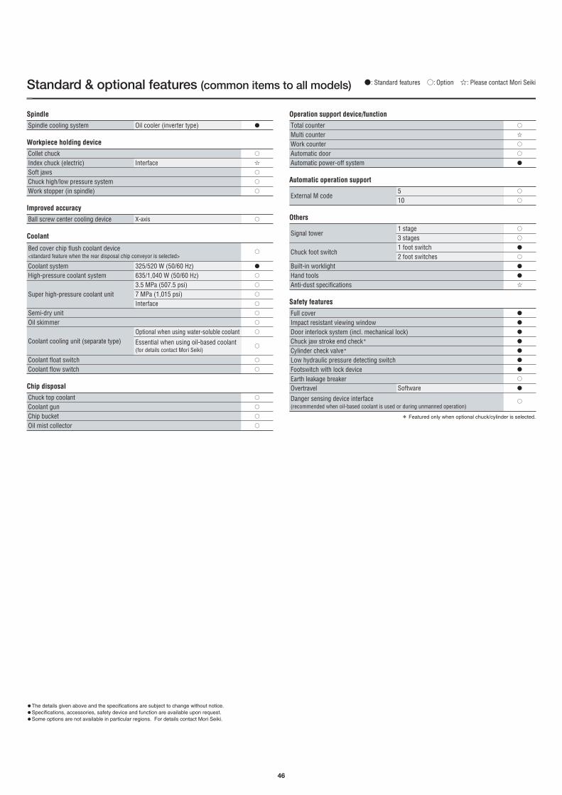
46
Spindle cooling system
Collet chuckIndex chuck (electric)Soft jawsChuck high/low pressure systemWork stopper (in spindle)
Interface
Oil cooler (inverter type)
Spindle
Workpiece holding device
Ball screw center cooling device X-axis
Improved accuracy
Bed cover chip flush coolant device <standard feature when the rear disposal chip conveyor is selected>
Coolant systemHigh-pressure coolant system
Super high-pressure coolant unit
Semi-dry unitOil skimmer
Coolant cooling unit (separate type)
Coolant float switchCoolant flow switch
325/520 W (50/60 Hz)635/1,040 W (50/60 Hz)3.5 MPa (507.5 psi)7 MPa (1,015 psi)Interface
Optional when using water-soluble coolant
Essential when using oil-based coolant(for details contact Mori Seiki)
Coolant
Chuck top coolantCoolant gunChip bucketOil mist collector
Chip disposal
Total counterMulti counterWork counterAutomatic doorAutomatic power-off system
Operation support device/function
External M code510
Automatic operation support
Signal tower
Chuck foot switch
Built-in worklightHand toolsAnti-dust specifications
1 stage3 stages1 foot switch2 foot switches
Others
Full coverImpact resistant viewing windowDoor interlock system (incl. mechanical lock)Chuck jaw stroke end check*
Cylinder check valve*
Low hydraulic pressure detecting switchFootswitch with lock deviceEarth leakage breakerOvertravel
Danger sensing device interface(recommended when oil-based coolant is used or during unmanned operation)
Software
Safety features
●: Standard features ○: Option ☆: Please contact Mori SeikiStandard & optional features (common items to all models)
●
○
☆
○
○
○
○
○
●
○
○
○
○
○
○
○
○
○
○
○
○
○
○
○
☆
○
○
●
○
○
○
○
●
○
●
●
☆
○
●
○
●
●
●
●
●
●
●
* Featured only when optional chuck/cylinder is selected.
●The details given above and the specifications are subject to change without notice.●Specifications, accessories, safety device and function are available upon request.●Some options are not available in particular regions. For details contact Mori Seiki.
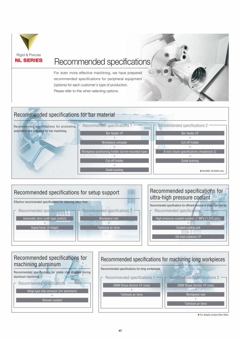
47
Recommended specificationsRigid & Precise
NL SERIES
For even more effective machining, we have prepared
recommended specifications for peripheral equipment
(options) for each customer’s type of production.
Please refer to this when selecting options.
Recommended specifications for bar material
Recommended specifications for promotingautomation and efficiency for bar machining.
Recommended specifications for setup supportEffective recommended specifications for reducing setup time.
Automatic door (with tape switch)
Recommended specifications 1
Workpiece rest
Recommended specifications 2
Recommended specifications 1 Recommended specifications 2
Bar feeder I/F+
Cut-off holder+
8 inch chuck specifications (headstock 2)+
Guide bushing
Bar feeder I/F+
Workpiece unloader+
Workpiece positioning holder (turret-mounted type)+
Cut-off holder+
Guide bushing
+
Signal tower (3-stage)+
Tailstock air blow
Recommended specifications for machining long workpiecesRecommended specifications for long workpieces.
SMW Brace Anchor I/F (one)
Recommended specifications 1
SMW Brace Anchor I/F (one)
Recommended specifications 2
+
Tailstock air blow+
Workpiece rest+
Tailstock air blow
Recommended specifications formachining aluminumRecommended specifications for stable chip disposal duringaluminum machining.
Hinge type chip conveyor (for aluminum)
Recommended specifications
+
Shower coolant
Recommended specifications forultra-high pressure coolantRecommended specifications for efficient removal of chips from tool tip.
High-pressure coolant system <7 MPa (1,015 psi)>
Recommended specifications
+
Coolant cooling unit+
Oil mist collector I/F
● NL2000, NL2500 only.
● For details contact Mori Seiki.

I/O interface
User memory area 50 MB(for card DNC operation function, for data backup)
Data serverExternal work number searchDNC operation with memory card
User memory area 500 MB(for card DNC operation function, for data backup)
Status displayClock functionActual position displayProgram displayParameter setting displaySelf-diagnosis functionAlarm displayAlarm history displayOperator’s message history displayOperation history displayHelp functionRunning time display/Number of parts displayActual feedrate displayDisplay of actual spindle speed and T codeOperation panel: display sectionRegular interval maintenance screen
Screen clear
Part program storageNumber of stored programsBackground editingExpanded tape editing functionUndo/Redo functionLine no. display function
Part program storage <in total>+Number of stored programs <in total>
Miscellaneous function Auxiliary function lock
Multiple miscellaneous function commandsSpindle speed functionConstant surface speed controlSpindle speed overrideSpindle orientation (headstock 1)Load monitoring function ASpindle orientation (headstock 1)Synchronized tapping
Optional block skipMax. command valueProgram numberSequence number
Decimal point programming/Electrical calculator type decimal point programming
Diameter/radius programming (X-axis)Plane selectionRotary axis designationRotary axis roll-overCoordinate system settingAutomatic coordinate system settingWork coordinate systemChamfer, corner RProgrammable data inputSub-program call
Custom macro
Interruption type custom macroSingle repetitive cycleMultiple repetitive cycleMultiple repetitive cycleⅡHole machining canned cycleF15 formatCommand angles of straight linesProgram numberAddition of optional block skip
Custom macro common variables<in total>
Automatic tool nose radius compensationGroove width compensationManual coordinate system functionTool geometry offset type Ⅰ
Rapid traverse rate overrideFeed per minuteFeed per revolutionConstant tangential velocity controlCutting feedrate clamp
Automatic acceleration/deceleration
Feedrate overrideOverride cancel
Positioning
Thread cutting/Synchronous feedMulti-start thread cuttingRetract during thread cutting cycleContinuous thread cuttingVariable lead thread cuttingHigh-speed skipMulti-skipZero returnZero return check2nd zero return3rd and 4th zero return
Sequence number collation and stopDry runSingle block
Jog feedrate
Manual zero return
Manual pulse handle feed
Program restartManual handle feed interruption
Least input incrementLeast command incrementMax. command valueInch/metric conversionMachine lockChuck and tailstock barrierChamfering on/offBacklash compensationRapid traverse/cutting feed backlash compensationStored pitch error compensation
Inclined angle offset
Straightness offset
Programming resolution multiplied by 1/10
Numerical control unit specifications (MSX-850Ⅲ)
Controlled axes0.001 mm (0.0001 in.)0.001 mm (0.0001 in.)±99,999.999 mm (±9,999.9999 in.)
Only works in automatic operation
G9,999 pulses
Memorized relative positioncompensation
0.0001 mm (0.00001 in.)<however, the C-axis control is 0.001˚>
Interpolation functions
linear interpolation type positioning is possible
Operation
0-5,000 mm/min(0-197.0 ipm) <20 steps>
1unit per control system: ×1, ×10, ×100
Program input1 block±8 digits4 digits5-digit N code
You can change the electrical calculatortype decimal point programming bychanging a parameter
Standard: diameter
Up to 8 nestings200 sets (# 100 to # 199, # 500 to # 599)
Pocket cutting, zigzag thread cutting
8 digitsSoft key type (2-9)
300 variables (# 100 to # 199, # 500 to # 699)
600 variables (# 100 to # 199, # 500 to # 999)
Miscellaneous function/Spindle speed function4-digit M code
3 commands (this function is standard for the specified M codes)5-digit S code
50-150% (10% increments)Without lock function
With software lockTurning spindle
Feed functionsF0/5/10/25/100%
Interpolation in cutting feed
Linear type (rapid traverse)/Exponential function type(cutting feed)
0-200% (10% increments)
Editing320 m (1,050 ft) <128 kB>200 programs
600 m (1,970 ft) <240 kB>+400 programs
1,280 m (4,200 ft) <512 kB>+1,000 programs
2,560 m (8,400 ft) <1 MB>+1,000 programs
5,120 m (16,800 ft) <2 MB>+1,000 programs
Data input/outputRS-232-C/PCMCIA (typeⅠ,Ⅱ)
Files up to 10 MB in size can beedited
# 1-# 15
Files up to 10 MB in size can beedited
Setting and display
Program name: 48 characters
10.4-inch TFT color LCD
It is possible to set on thescreen of saving electric power
I95011A05
Controlled axesControlled axesSimultaneously controllable axesInclined axis control for arbitrary axis (Y-axis)Polar coordinate interpolationCylindrical interpolation
Helical interpolation (circular interpolation+linear interpolation <max. 2 axes>)
Polygon cutting
Absolute (incremental) programming
Spindle orientation (headstock 2) <without lock function>Spindle orientation (headstock 2) <with software lock>Spindle synchronized controlMultiple-spindle controlSynchronized tapping (with rotary tool spindle)
Y-axis offset
Interpolation functions
Program input
Miscellaneous function/Spindle speed function
Tool function/Tool offset function
■ Application by typeItem 2-axis turning MC-type Y-type S-type SMC-type SY-type
X, Z, B, 4X, Z
X (U), Z (W)
X, Z, C, B, 5X, Z, C
X (U), Z (W), C (H)
X, Z, C, Y, B, 6X, Z, C, Y
X (U), Z (W), Y (V), C (H)
X, Z, B, 4X, Z
X (U), Z (W), B
X, Z, C, B, 5X, Z, C
X (U), Z (W), C (H), B
X, Z, C, Y, B, 6X, Z, C, Y
X (U), Z (W), Y (V), C (H), B
48
●: Standard ○: Option ×: Not available
●
●
●
●
●
●
●
●
●
●
●
●
○
●
●
●
●
●
●
○
○
●
●
●
●
●
●
●
●
●
●
●
●
●
●
●
●
●
●
●
●
●
●
●
●
●
●
●
●
●
●
●
○
○
○
○
○
○
○
○
●
●
●
●
●
●
●
●
○
○
●
●
●
●
●
●
○
○
○
○
●
●
●
●
●
●
●
●
●
●
●
●
●
●
●
●
●
●
●
○
○
○
○
●
●
●
●
●
●
●
●
●
●
●
●
●
●
×
×
×
×
×
●
×
×
×
×
×
×
●
●
×
●
●
○
○
●
×
×
×
●
●
×
●
●
●
●
●
●
○
●
×
×
×
●
●
●
●
●
×
×
×
×
×
●
●
○
●
●
×
×
●
●
×
●
●
○
○
●
●
○
●
●
●
×
●
●
●
●
●
●
○
●
●
○
●
●
●
●
Tool functionNumber of tool offsetsTool position offsetTool nose radius offsetTool geometry offset/Tool wear offsetTool life management
7-digit tool offset data
Tool offset measurement direct data input
Tool offset measurement direct data input B
Tool function/Tool offset function4-digit T code80 sets
80 sets
Distance between centers 1250type and 2000 type only
In-machine tool presetter
●
●
●
●
●
●
●
●
●

49
Machine size
NL1500Without sub-spindle
With sub-spindle
NL2000Without sub-spindle
With sub-spindle
NL2500/700Without sub-spindle
With sub-spindle
NL2500/1250
NL3000/700
NL3000/1250
NL3000/2000
NL3000/3000
2,232 (87.9)
2,270 (89.4)
2,390 (94.1)
2,120 (83.5)
2,695 (106.1)
3,100 (122.0)
4,329 (170.4)
3,410 (134.3)
4,522 (178.0)
-
-
3,388 (133.4)
3,805 (149.8)
5,039 (198.4)
4,092 (161.1)
5,184 (204.1)
7,080 (278.7)
8,147 (320.7)
3,688 (145.2)
4,105 (161.6)
5,339 (210.2)
4,392 (172.9)
5,484 (215.9)
7,417 (292.0)
8,484 (334.0)
1,005 (39.6)
1,000 (39.4)
1,055 (41.5)
1,922 (75.7)
2,000 (78.7)
1,922 (75.7)
2,000 (78.7)
1,922 (75.7)
2,000 (78.7)
2,143 (84.4)
2,089 (82.2)
2,291 (90.2)
2,587 (101.9)
3,150 (124.0)
3,325 (130.9)
3,432 (135.1)
3,464 (136.4)
4,494 (176.9)1,020 (40.2) 1,042 (41.0)
Machine typeHeight
Width
Including chip conveyor<EN Standards> Standard EN Standards Machine onlyMachine only
A B C D G FE H
Including chip conveyor
Including space to removecoolant tank
Chip conveyor disposal height Depth
A
B
C
G
H
F
D, E
Front view Side view
<chip conveyors arestandard>
<chip conveyors arestandard>
<chip conveyors arestandard>
<chip conveyors arestandard>
mm (in.)

NL1500MC/500 NL1500Y/500 NL1500S/500 NL1500SMC/500 NL1500SY/500
Capacity
NL1500/500Item
Travel
Spindle
Turret
Feedrate
Tailstock
Power sources
Tank capacity
Machine size
Motor
[ ]Option JIS: Japanese Industrial Standard●Bar work capacity: depending on the chuck/cylinder used and its restrictions, it may not be possible to reach full bar work capacity. ●Max. spindle speed: depending on restrictions imposed by the workpiece clamping device, fixture and tool used, it may not be possible to rotate at the maximum spindle speed.●ANR: ANR refers to a standard atmospheric state; i. e., temperature at 20 ℃ (68 ゚F), absolute pressure at 101.3 kPa (14.7 psi) and relative humidity at 65%.● Power sources, machine size: the actual values may differ from those specified in the catalogue, depending on the optional features and peripheral equipment.
Swing over bed mm (in.)
Swing over cross slide mm (in.)
Max. turning diameter mm (in.)
Standard turning diameter mm (in.)
Max. turning length mm (in.)
Bar work capacity mm (in.)
X-axis travel mm (in.)
Z-axis travel mm (in.)
Y-axis travel mm (in.)
Headstock 2 travel <B-axis> mm (in.)
Max. spindle speed min-1
Type of spindle nose
Through-spindle hole diameter mm (in.)
Min. spindle indexing angle
Spindle bearing inner diameter mm (in.)
Number of tool stations
Shank height for square tool mm (in.)
Shank diameter for boring bar mm (in.)
Tool shank diameter for rotary tool mm (in.)
Turret indexing time s
Max. rotary tool spindle speed min-1
Rapid traverse rate mm/min (ipm)
Tailstock travel mm (in.)
Tailstock spindle diameter mm (in.)
Taper hole of tailstock spindle
Spindle drive motor kW (HP)<50%ED/30min/cont>
kW (HP)
Rotary tool spindle drive motor <3 min/5 min/cont> kW (HP)
Feed motor kW (HP)
Electrical power supply kVA<for the standard specifications>
Compressed air supply MPa (psi), L/min (gpm)
Coolant tank capacity L (gal.)
Machine height <from floor> mm (in.)
Floor space <width×depth> mm (in.)
Mass of machine kg (lb.)
923.8 (36.4) <interference with front cover 579.8 (22.8)>
755 (29.7)
356 (14.0) [278 (10.9) <20-station turret head>]
260 (10.2) [192.6 (7.5) <20-station turret head>]
515 (20.2)
52 (2.0) [34 (1.3) <8,000 min-1>]
260 (10.2)
590 (23.2) [580 (22.8) <20-station turret head>]
12 [16] [20]
20 (3/4)
100 <±50> (3.9 <±2.0>)-
-
6,000 [8,000]
JIS A2-5
61 (2.4) [43 (1.7) <8,000 min-1>] Headstock 1: 61 (2.4) [43 (1.7) <8,000 min-1>]Headstock 2: 43 (1.7)
624 (24.6)
Headstock 1, 2: 6,000 [8,000]
Headstock 1, 2: JIS A2-5
Headstock 1: 100 (3.9) [85 (3.3) <8,000 min-1>] Headstock 2: 85 (3.3)
100 (3.9) [85 (3.3) <8,000 min-1>]
Max. 40 (11/2) [32 (11/4) <double boring holder>]
ー
0.2 [0.25<20-station turret head>]
ー
ー
0.2 [0.25<20-station turret head>]
ー
26 (1.0)
0.25
6,000
26 (1.0)
0.25
6,000
Headstock 1: Max. 40 (11/2) [32 (11/4) <double boring holder>]Headstock 2: Max. 32 (11/4)
- 0.001゜ - 0.001゜
11/11/7.5 (15/15/10) [15/15/11 (20/20/15)]
[11/7.5 (15/10) <25%ED/cont>]
6,000 min-1
8,000 min-1
235 (62.0)
2,120 (83.5)
X, Y: 2.0 (2.7) Z: 3.5 (4.7)
27.2
ー(a compressed air supply may be needed, depending on options and peripheral equipment)
5,600 (12,320)5,300 (11,660)
2,695×1,922 (106.1×75.7) 2,695×2,000 (106.1×78.7)
5,400 (11,880) 5,400 (11,880)
564 (22.2)
80 (3.1)
Live center <MT4> [Built-in center <MT3>]
X, Z: 30,000 (1,181.1)Tailstock: 7,000 (275.6)
X, Z: 30,000 (1,181.1)Tailstock: 7,000 (275.6)
C: 400 min-1
X, Z: 30,000 (1,181.1)Y: 10,000 (393.7)
Tailstock: 7,000 (275.6)C: 400 min-1
X, Z, B: 30,000(1,181.1)
X, Z, B: 30,000(1,181.1)
C: 400 min-1
ー
ー
ー
5.5/5.5/3.7 (7.5/7.5/5)
X: 2.0 (2.7) Z: 3.5 (4.7) X, B: 2.0 (2.7) Z: 3.5 (4.7)
ー
18.8 23.3
5.5/5.5/3.7 (7.5/7.5/5)ー
27.3
X, Y, B: 2.0 (2.7) Z: 3.5 (4.7)
31.627.2
X, Z, B: 30,000(1,181.1)
Y: 10,000 (393.7)C: 400 min-1
Headstock 1: 11/11/7.5 (15/15/10) [15/15/11 (20/20/15)] Headstock 2: 11/7.5 (15/10) <25%ED/cont>
Headstock 1, 2: [11/7.5 (15/10) <25%ED/cont>]
5,700 (12,540)5,500 (12,100)
100 <±50> (3.9 <±2.0>)-
I94028A04
Machine specifications (NL1500)
0.5 (72.5), 100 (26.4) <ANR>
50

Machine specifications (NL2000)
51
Power sources
Tank capacity
Motor
235 (62.0)
2,120 (83.5)
0.5 (72.5), 100 (26.4) <ANR>
ー
ー
ー
5.5/5.5/3.7 (7.5/7.5/5)
X, Y, B: 2.0 (2.7) Z: 3.5 (4.7)
35.7
Headstock 1: 15/15/11 (20/20/15) [18.5/18.5/18.5/15 (24.7/24.7/24.7/20)
<25%ED/50%ED/30 min/cont>]Headstock 2: 11/7.5 (15/10) <25%ED/cont>
5,800 (12,760)
NL2000MC/500 NL2000Y/500 NL2000S/500 NL2000SMC/500 NL2000SY/500
Capacity
NL2000/500Item
Travel
Spindle
[ ]Option JIS: Japanese Industrial Standard●Bar work capacity: depending on the chuck/cylinder used and its restrictions, it may not be possible to reach full bar work capacity. ●Max. spindle speed: depending on restrictions imposed by the workpiece clamping device, fixture and tool used, it may not be possible to rotate at the maximum spindle speed.●ANR: ANR refers to a standard atmospheric state; i. e., temperature at 20 ℃ (68 ゚F), absolute pressure at 101.3 kPa (14.7 psi) and relative humidity at 65%.●Power sources, machine size: the actual values may differ from those specified in the catalogue, depending on the optional features and peripheral equipment.
923.8 (36.4) <interference with front cover 579.8 (22.8)>
755 (29.7)
356 (14.0) [278 (10.9) <20-station turret head>]
275 (10.8) [192.6 (7.5) <20-station turret head>]
510 (20.0)
65 (2.5)
260 (10.2)
590 (23.2) [580 (22.8) <20-station turret head>]
100 <±50> (3.9 <±2.0>)ー
-
5,000
JIS A2-6
73 (2.9)
624 (24.6)
Headstock 1: 5,000 Headstock 2: 6,000 [5,000]
Headstock 1: JIS A2-6 Headstock 2: JIS A2-5 [JIS A2-6 <5,000 min-1>]
Headstock 1: 73 (2.9) Headstock 2: 43 (1.7) [73 (2.9) <5,000 min-1>]
Headstock 1: 120 (4.7) Headstock 2: 85 (3.3) [120 (4.7) <5,000 min-1>]120 (4.7)
ー 0.001゜ 0.001゜ー
100 <±50> (3.9 <±2.0>)ー
Turret
Feedrate
Tailstock
12 [10] [16] [20]
25 (1)
Max. 50 (2) [32 (11/4) <double boring holder>]
ー
0.2 [0.25<20-station turret head>]
ー
ー
0.2 [0.25<20-station turret head>]
ー
26 (1.0)
0.25
6,000
26 (1.0)
0.25
6,000
Headstock 1: Max. 50 (2) [32 (11/4) <double boring holder>] Headstock 2: Max. 32 (11/4)
15/15/11 (20/20/15) [18.5/18.5/18.5/15 (24.7/24.7/24.7/20)
<25%ED/50%ED/30 min/cont>]
X, Y: 2.0 (2.7) Z: 3.5 (4.7)
31.3
ー(a compressed air supply may be needed, depending on options and peripheral equipment)
5,700 (12,540)5,400 (11,880)
2,695×1,922 (106.1×75.7) 2,695×2,000 (106.1×78.7)
5,500 (12,100)
564 (22.2)
80 (3.1)
Live center <MT4> [Built-in center <MT3>]
X, Z: 30,000 (1,181.1)Tailstock: 7,000 (275.6)
X, Z: 30,000 (1,181.1)Tailstock: 7,000 (275.6)
C: 400 min-1
X, Z: 30,000 (1,181.1)Y: 10,000 (393.7)
Tailstock: 7,000 (275.6)C: 400 min-1
X, Z, B: 30,000(1,181.1)
X, Z, B: 30,000(1,181.1)
C: 400 min-1
5.5/5.5/3.7 (7.5/7.5/5)
X: 2.0 (2.7) Z: 3.5 (4.7) X, B: 2.0 (2.7) Z: 3.5 (4.7)
ー
20.3 24.0
ー
31.3
X, Z, B: 30,000(1,181.1)
Y: 10,000 (393.7)C: 400 min-1
5,600 (12,320)5,500 (12,100)
Swing over bed mm (in.)
Swing over cross slide mm (in.)
Max. turning diameter mm (in.)
Standard turning diameter mm (in.)
Max. turning length mm (in.)
Bar work capacity mm (in.)
X-axis travel mm (in.)
Z-axis travel mm (in.)
Y-axis travel mm (in.)
Headstock 2 travel <B-axis> mm (in.)
Max. spindle speed min-1
Type of spindle nose
Through-spindle hole diameter mm (in.)
Min. spindle indexing angle
Spindle bearing inner diameter mm (in.)
Number of tool stations
Shank height for square tool mm (in.)
Shank diameter for boring bar mm (in.)
Tool shank diameter for rotary tool mm (in.)
Turret indexing time s
Max. rotary tool spindle speed min-1
Rapid traverse rate mm/min (ipm)
Tailstock travel mm (in.)
Tailstock spindle diameter mm (in.)
Taper hole of tailstock spindle
Spindle drive motor kW (HP)<50%ED/30 min/cont>
Rotary tool spindle drive motor<3 min/5 min/cont> kW (HP)
Feed motor kW (HP)
Electrical power supply kVA<for the standard specifications>
Compressed air supply MPa (psi), L/min (gpm)
Coolant tank capacity L (gal.)
Machine height <from floor> mm (in.)
Floor space <width×depth> mm (in.)
Mass of machine kg (lb.)I94029A04
Machine size

52
Machine specifications (NL2500/700)
NL2500MC/700 NL2500Y/700 NL2500S/700 NL2500SMC/700 NL2500SY/700
Capacity
NL2500/700Item
Travel
Spindle
Turret
Feedrate
Tailstock
Power sources
Tank capacity
Machine size
Motor
[ ]Option JIS: Japanese Industrial Standard●Bar work capacity: depending on the chuck/cylinder used and its restrictions, it may not be possible to reach full bar work capacity. ●Max. spindle speed: depending on restrictions imposed by the workpiece clamping device, fixture and tool used, it may not be possible to rotate at the maximum spindle speed.●ANR: ANR refers to a standard atmospheric state; i. e., temperature at 20 ℃ (68 ゚F), absolute pressure at 101.3 kPa (14.7 psi) and relative humidity at 65%.● Power sources, machine size: the actual values may differ from those specified in the catalogue, depending on the optional features and peripheral equipment.
Swing over bed mm (in.)
Swing over cross slide mm (in.)
Max. turning diameter mm (in.)
Standard turning diameter mm (in.)
Max. turning length mm (in.)
Bar work capacity mm (in.)
X-axis travel mm (in.)
Z-axis travel mm (in.)
Y-axis travel mm (in.)
Headstock 2 travel <B-axis> mm (in.)
Max. spindle speed min-1
Type of spindle nose
Through-spindle hole diameter mm (in.)
Min. spindle indexing angle
Spindle bearing inner diameter mm (in.)
Number of tool stations
Shank height for square tool mm (in.)
Shank diameter for boring bar mm (in.)
Tool shank diameter for rotary tool mm (in.)
Turret indexing time s
Max. rotary tool spindle speed min-1
Rapid traverse rate mm/min (ipm)
Tailstock travel mm (in.)
Tailstock spindle diameter mm (in.)
Taper hole of tailstock spindle
Spindle drive motor kW (HP)
<25%ED/50%ED/cont>
Rotary tool spindle drive motor <3 min/5 min/cont> kW (HP)
Feed motor kW (HP)
Electrical power supply kVA<for the standard specifications>
Compressed air supply MPa (psi), L/min (gpm)
Coolant tank capacity L (gal.)
Machine height <from floor> mm (in.)
Floor space <width×depth> mm (in.)
Mass of machine kg (lb.)
923.8 (36.4) <interference with front cover 579.8 (22.8)>
755 (29.7)
356 (14.0)
275 (10.8)
705 (27.7)
80 (3.1)
260 (10.2)
795 (31.3)
12 [10]
25 (1)
100 <±50> (3.9 <±2.0>)ー
-
4,000
JIS A2-8
91 (3.6)
734 (28.9)
Headstock 1: 4,000 Headstock 2: 6,000 [5,000]
Headstock 1: JIS A2-8 Headstock 2: JIS A2-5 [JIS A2-6 <5,000 min-1>]
Headstock 1: 91 (3.6) Headstock 2: 43 (1.7) [73 (2.9) <5,000 min-1>]
Headstock 1: 140 (5.5) Headstock 2: 85 (3.3) [120 (4.7) <5,000 min-1>]140 (5.5)
Max. 50 (2) [32 (11/4) <double boring holder>]
ー
0.2
ー
ー
0.2
ー
26 (1.0)
0.25
6,000
26 (1.0)
0.25
6,000
Headstock 1: Max. 50 (2) [32 (11/4) <double boring holder>]Headstock 2: Max. 32 (11/4)
18.5/18.5/15 (24.7/24.7/20)[26/26/22 (34.7/34.7/30) <10 min/30 min/cont>]
246 (64.9)
2,120 (83.5)
X, Z, Y: 3.5 (4.7)
36.4
ー(a compressed air supply may be needed, depending on options and peripheral equipment)
0.5 (72.5), 100 (26.4) <ANR>
6,100 (13,420)5,800 (12,760) 5,900 (12,980)
734 (28.9)
80 (3.1)
Live center <MT5> [Built-in center <MT3>] [Built-in center <MT4>]
X, Z: 30,000 (1,181.1)Tailstock: 7,000 (275.6)
X, Z: 30,000 (1,181.1)Tailstock: 7,000 (275.6)
C: 400 min-1
X, Z: 30,000 (1,181.1)Y: 10,000 (393.7)
Tailstock: 7,000 (275.6)C: 400 min-1
X, Z, B: 30,000(1,181.1)
X, Z, B: 30,000(1,181.1)
C: 400 min-1
ー
ー
ー
5.5/5.5/3.7 (7.5/7.5/5)ー
27.8 32.0
5.5/5.5/3.7 (7.5/7.5/5)ー
X, Z, Y: 3.5 (4.7) B: 2.0 (2.7)
39.436.4
X, Z, B: 30,000(1,181.1)
Y: 10,000 (393.7)C: 400 min-1
Headstock 1: 18.5/18.5/15 (24.7/24.7/20) [26/26/22 (34.7/34.7/30) <10 min/30 min/cont>]
Headstock 2: 11/7.5 (15/10) <25%ED/cont>
6,200 (13,640)
100 <±50> (3.9 <±2.0>)ー
6,000 (13,200)I94030A04
5,900 (12,980)
ー 0.001゜ 0.001゜ー
X, Z: 3.5 (4.7) X, Z: 3.5 (4.7) B: 2.0 (2.7)
3,100×1,922 (122.0×75.7) 3,100×2,000 (122.0×78.7)
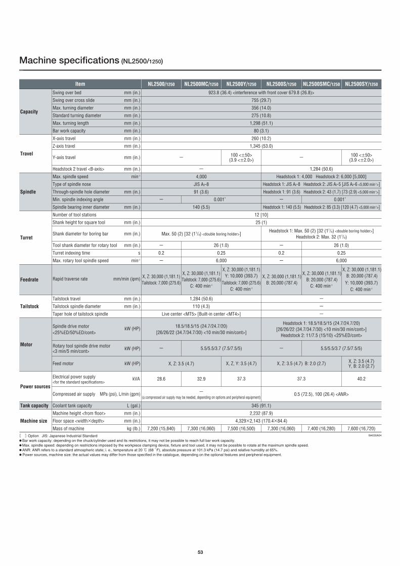
53
Machine specifications (NL2500/1250)
NL2500MC/1250 NL2500Y/1250 NL2500S/1250 NL2500SMC/1250 NL2500SY/1250
Capacity
NL2500/1250Item
Travel
Spindle
Turret
Feedrate
Tailstock
Power sources
Tank capacity
Machine size
Motor
[ ]Option JIS: Japanese Industrial Standard●Bar work capacity: depending on the chuck/cylinder used and its restrictions, it may not be possible to reach full bar work capacity. ●Max. spindle speed: depending on restrictions imposed by the workpiece clamping device, fixture and tool used, it may not be possible to rotate at the maximum spindle speed.●ANR: ANR refers to a standard atmospheric state; i. e., temperature at 20 ℃ (68 ゚F), absolute pressure at 101.3 kPa (14.7 psi) and relative humidity at 65%.● Power sources, machine size: the actual values may differ from those specified in the catalogue, depending on the optional features and peripheral equipment.
Swing over bed mm (in.)
Swing over cross slide mm (in.)
Max. turning diameter mm (in.)
Standard turning diameter mm (in.)
Max. turning length mm (in.)
Bar work capacity mm (in.)
X-axis travel mm (in.)
Z-axis travel mm (in.)
Y-axis travel mm (in.)
Headstock 2 travel <B-axis> mm (in.)
Max. spindle speed min-1
Type of spindle nose
Through-spindle hole diameter mm (in.)
Min. spindle indexing angle
Spindle bearing inner diameter mm (in.)
Number of tool stations
Shank height for square tool mm (in.)
Shank diameter for boring bar mm (in.)
Tool shank diameter for rotary tool mm (in.)
Turret indexing time s
Max. rotary tool spindle speed min-1
Rapid traverse rate mm/min (ipm)
Tailstock travel mm (in.)
Tailstock spindle diameter mm (in.)
Taper hole of tailstock spindle
Spindle drive motor kW (HP)<25%ED/50%ED/cont>
Rotary tool spindle drive motor<3 min/5 min/cont> kW (HP)
Feed motor kW (HP)
Electrical power supply kVA<for the standard specifications>
Compressed air supply MPa (psi), L/min (gpm)
Coolant tank capacity L (gal.)
Machine height <from floor> mm (in.)
Floor space <width×depth> mm (in.)
Mass of machine kg (lb.)
923.8 (36.4) <interference with front cover 679.8 (26.8)>
755 (29.7)
356 (14.0)
275 (10.8)
1,298 (51.1)
80 (3.1)
260 (10.2)
1,345 (53.0)
12 [10]
25 (1)
100 <±50> (3.9 <±2.0>)ー
-
4,000
JIS A2-8
91 (3.6)
1,284 (50.6)
Headstock 1: 4,000 Headstock 2: 6,000 [5,000]
Headstock 1: JIS A2-8 Headstock 2: JIS A2-5 [JIS A2-6 <5,000 min-1>]
Headstock 1: 91 (3.6) Headstock 2: 43 (1.7) [73 (2.9) <5,000 min-1>]
Headstock 1: 140 (5.5) Headstock 2: 85 (3.3) [120 (4.7) <5,000 min-1>]140 (5.5)
Max. 50 (2) [32 (11/4) <double boring holder>]
ー
0.2
ー
ー
0.2
ー
26 (1.0)
0.25
6,000
26 (1.0)
0.25
6,000
Headstock 1: Max. 50 (2) [32 (11/4) <double boring holder>]Headstock 2: Max. 32 (11/4)
ー 0.001゜ ー 0.001゜
18.5/18.5/15 (24.7/24.7/20)[26/26/22 (34.7/34.7/30) <10 min/30 min/cont>]
345 (91.1)
2,232 (87.9)
4,329×2,143 (170.4×84.4)
X, Z, Y: 3.5 (4.7)
37.3
ー(a compressed air supply may be needed, depending on options and peripheral equipment)
0.5 (72.5), 100 (26.4) <ANR>
7,500 (16,500)7,200 (15,840) 7,300 (16,060)
1,284 (50.6)
110 (4.3)
Live center <MT5> [Built-in center <MT4>]
X, Z: 30,000 (1,181.1)Tailstock: 7,000 (275.6)
X, Z: 30,000 (1,181.1)Tailstock: 7,000 (275.6)
C: 400 min-1
X, Z: 30,000 (1,181.1)Y: 10,000 (393.7)
Tailstock: 7,000 (275.6)C: 400 min-1
X, Z: 30,000 (1,181.1)B: 20,000 (787.4)
X, Z: 30,000 (1,181.1)B: 20,000 (787.4)
C: 400 min-1
ー
ー
ー
5.5/5.5/3.7 (7.5/7.5/5)
X, Z: 3.5 (4.7)
ー
28.6 32.9
5.5/5.5/3.7 (7.5/7.5/5)ー
X, Z: 3.5 (4.7)Y, B: 2.0 (2.7)
40.2
X, Z: 3.5 (4.7) B: 2.0 (2.7)
37.3
X, Z: 30,000 (1,181.1)B: 20,000 (787.4)
Y: 10,000 (393.7)C: 400 min-1
Headstock 1: 18.5/18.5/15 (24.7/24.7/20) [26/26/22 (34.7/34.7/30) <10 min/30 min/cont>]
Headstock 2: 11/7.5 (15/10) <25%ED/cont>
7,600 (16,720)
100 <±50> (3.9 <±2.0>)ー
7,400 (16,280)I94030A04
7,300 (16,060)

54
Machine specifications (NL3000/700, NL3000/1250)
NL3000MC/700 NL3000Y/700 NL3000/1250 NL3000MC/1250 NL3000Y/1250
Capacity
NL3000/700Item
Travel
Spindle
Turret
Feedrate
Tailstock
Power sources
Tank capacity
Machine size
Motor
[ ]Option JIS: Japanese Industrial Standard●Bar work capacity: depending on the chuck/cylinder used and its restrictions, it may not be possible to reach full bar work capacity. ●Max. spindle speed: depending on restrictions imposed by the workpiece clamping device, fixture and tool used, it may not be possible to rotate at the maximum spindle speed.● Power sources, machine size: the actual values may differ from those specified in the catalogue, depending on the optional features and peripheral equipment.
995 (39.2) <interference with front cover 700 (27.6)>995 (39.2) <interference with front cover 670 (26.4)>
825 (32.5)
310 (12.2)
90 (3.5)
280 (11.0) <210+70 (8.3+2.8)>
10 [12]
25 (1)
Max. 50 (2)
0.3
120 <±60>(4.7 <±2.4>) ー
820 (32.3)
3,000
JIS A2-8
105 (4.1)
1,370 (53.9)
713 (28.0) 1,260 (49.6)
160 (6.3)
ー
110 (4.3)
Live center <MT5> [Built-in center <MT4>]
22/18.5 (30/24.7) [30/25 (40/33.3)]
ー(a compressed air supply may be needed, depending on options and peripheral equipment)
ー6,000 6,000
ー ー26 (1.0) 26 (1.0)
ー 0.001゜ー 0.001゜
420 (16.5)
300 (79.2)
2,270 (89.4)
370 (97.7)
2,390 (94.1)
4,522×2,291 (178.0×90.2)
X, Z, Y: 3.5 (4.7)
40.3
6,500 (14,300)6,000 (13,200)
3,410×2,089 (134.3×82.2)
8,100 (17,820)7,600 (16,720)
734 (28.9)
X, Z: 30,000 (1,181.1)Tailstock: 7,000 (275.6)
X, Z: 30,000 (1,181.1)Tailstock: 7,000 (275.6)
C: 300 min-1
X, Z: 3.5 (4.7) X, Z: 3.5 (4.7)
X, Z: 30,000 (1,181.1)Y: 10,000 (393.7)
Tailstock: 7,000 (275.6)C: 300 min-1
X, Z: 30,000 (1,181.1)Tailstock: 7,000 (275.6)
X, Z: 30,000 (1,181.1)Tailstock: 7,000 (275.6)
C: 300 min-1
1,284 (50.6)
5.5/5.5/3.7 (7.5/7.5/5)ー
33.1 38.7
5.5/5.5/3.7 (7.5/7.5/5)ー
33.1
X, Z, Y: 3.5 (4.7)
40.338.7
X, Z: 30,000 (1,181.1)Y: 10,000 (393.7)
Tailstock: 7,000 (275.6)C: 300 min-1
120 <±60>(4.7 <±2.4>) ー
I94031A04
Swing over bed mm (in.)
Swing over cross slide mm (in.)
Max. turning diameter mm (in.)
Standard turning diameter mm (in.)
Max. turning length mm (in.)
Bar work capacity mm (in.)
X-axis travel mm (in.)
Z-axis travel mm (in.)
Y-axis travel mm (in.)
Max. spindle speed min-1
Type of spindle nose
Through-spindle hole diameter mm (in.)
Min. spindle indexing angle
Spindle bearing inner diameter mm (in.)
Number of tool stations
Shank height for square tool mm (in.)
Shank diameter for boring bar mm (in.)
Tool shank diameter for rotary tool mm (in.)
Turret indexing time s
Max. rotary tool spindle speed min-1
Rapid traverse rate mm/min (ipm)
Tailstock travel mm (in.)
Tailstock spindle diameter mm (in.)
Taper hole of tailstock spindle
Spindle drive motor <30 min/cont> kW (HP)
Rotary tool spindle drive motor<3 min/5 min/cont> kW (HP)
Feed motor kW (HP)
Electrical power supply kVA<for the standard specifications>
Compressed air supply MPa (psi), L/min (gpm)
Coolant tank capacity L (gal.)
Machine height <from floor> mm (in.)
Floor space <width×depth> mm (in.)
Mass of machine kg (lb.)

55
Machine specifications (NL3000/2000, NL3000/3000)
NL3000MC/2000 NL3000Y/2000 NL3000/3000 NL3000MC/3000 NL3000Y/3000NL3000/2000Item
Capacity
Travel
Spindle
Turret
Feedrate
Tailstock
Power sources
Tank capacity
Machine size
Motor
[ ]Option JIS: Japanese Industrial Standard●Bar work capacity: depending on the chuck/cylinder used and its restrictions, it may not be possible to reach full bar work capacity. ●Max. spindle speed: depending on restrictions imposed by the workpiece clamping device, fixture and tool used, it may not be possible to rotate at the maximum spindle speed.● Power sources, machine size: the actual values may differ from those specified in the catalogue, depending on the optional features and peripheral equipment.
995 (39.2) <interference with front cover 963 (37.9)>
825 (32.5)
310 (12.2)
90 (3.5)
280 (11.0) <210+70 (8.3+2.8)>
10 [12]
25 (1)
50 (2)
0.3
120 <±60>(4.7 <±2.4>) ー
2,170 (85.4)
3,000
JIS A2-8
105 (4.1)
3,170 (124.8)
2,123 (83.5) 3,123 (122.9)
160 (6.3)
ー
150 (5.9)
150 (5.9)
Built-in center <MT5>
22/18.5 (30/24.7) [30/25 (40/33.3)]
ー(a compressed air supply may be needed, depending on options and peripheral equipment)
2,390 (94.1)
ー6,000 6,000
ー 0.001゜ー 0.001゜
420 (16.5)
470 (124.1) 540 (142.6)
8,147×2,587 (320.7×101.9) <depth includes operation panel>
X, Y: 3.5 (4.7) Z: 7.0 (9.3)
42.4
12,000 (26,400)11,500 (25,300)
7,080×2,587 (278.7×101.9) <depth includes operation panel>
14,000 (30,800)13,500 (29,700)
2,164 (85.2)
X, Z: 30,000 (1,181.1)X, Z: 30,000 (1,181.1)
C: 300 min-1
X: 3.5 (4.7) Z: 7.0 (9.3) X: 3.5 (4.7) Z: 7.0 (9.3)
X, Z: 30,000 (1,181.1)Y: 10,000 (393.7)
C: 300 min-1
X, Z: 30,000 (1,181.1)X, Z: 30,000 (1,181.1)
C: 300 min-1
3,164 (124.6)
5.5/3.7 (7.5/5)ー
35.3 40.9
5.5/3.7 (7.5/5)ー
35.3
X, Y: 3.5 (4.7)Z: 7.0 (9.3)
42.440.9
X, Z: 30,000 (1,181.1)Y: 10,000 (393.7)
C: 300 min-1
120 <±60>(4.7 <±2.4>) ー
I94031A04
Swing over bed mm (in.)
Swing over cross slide mm (in.)
Max. turning diameter mm (in.)
Standard turning diameter mm (in.)
Max. turning length mm (in.)
Bar work capacity mm (in.)
X-axis travel mm (in.)
Z-axis travel mm (in.)
Y-axis travel mm (in.)
Max. spindle speed min-1
Type of spindle nose
Through-spindle hole diameter mm (in.)
Min. spindle indexing angle
Spindle bearing inner diameter mm (in.)
Number of tool stations
Shank height for square tool mm (in.)
Shank diameter for boring bar mm (in.)
Turret indexing time s
Max. rotary tool spindle speed min-1
Rapid traverse rate mm/min (ipm)
Tailstock travel mm (in.)
Tailstock spindle diameter mm (in.)
Tailstock spindle travel mm (in.)
Taper hole of tailstock spindle
Spindle drive motor <30 min/cont> kW (HP)
Rotary tool spindle drive motor<5 min/cont> kW (HP)
Feed motor kW (HP)
Electrical power supply kVA<for the standard specifications>
Compressed air supply MPa (psi), L/min (gpm)
Coolant tank capacity L (gal.)
Machine height <from floor> mm (in.)
Floor space <width×depth> mm (in.)(including chip conveyor)
Mass of machine kg (lb.)
Nagoya Head Office 2-35-16 Meieki, Nakamura-ku, Nagoya City, Aichi 450-0002, Japan Phone: (052) 587-1811
Nara Campus No. 1 Plant 362 Idono-cho, Yamato-Koriyama City, Nara 639-1183, Japan Phone: (0743) 53-1121
Nara Campus No. 2 Plant 106 Kita-Koriyama-cho, Yamato-Koriyama City, Nara 639-1160, Japan Phone: (0743) 53-1125
Iga Campus 201 Midai, Iga City, Mie 519-1414, Japan Phone: (0595) 45-4151
Chiba Campus 488-19 Suzumi-cho, Funabashi City, Chiba 274-0052, Japan Phone: (047) 410-8800
● The export of this product is subject to an authorization from the government of the exporting country. Check with the government agency for authorization.
NLSERIES-EE02D.0708.CDT.0000
Created in Japan
● If you have any questions regarding the content, contact your nearest Mori Seiki distributor or Technical Center.● The information in this catalog is valid as of August 2007. Design and specifications subject to changes without notice. ●Mori Seiki is not responsible for differences between the information in the catalog and the actual machine.