
NIVOTRACK - Úvod - MICROWELL · NIVOTRACK magnetostrictive transmitters are an ideal solution for...
6
OUR PROFESSION IS YOUR LEVEL 0,1 mm resolution NIVOTRACK MAGNETOSTRICTIVE TRANSMITTERS LEVEL TRANSMITTERS
Transcript of NIVOTRACK - Úvod - MICROWELL · NIVOTRACK magnetostrictive transmitters are an ideal solution for...

O U R P R O F E S S I O N I S Y O U R L E V E L
0,1 mm resolution
NIVOTRACKM A G N E TO S T R I C T I V E T R A N S M I T T E R S
LE
VE
L T
RA
NS
MIT
TE
RS
NIVOTRACK MAGNETOSTRICTIVE TRANSMITTERS
MAIN FEATURES APPLICATIONSCustody transfer measurementOil and gas industryFuels and gasoline productsPharmaceutical industryChemical industryFood industryAlcohols and beveragesInstallation in bypass tubes feasibleSupplementary level transmitter forNIVOFLIP magnetic flip indicator
0,1 mm or 1 mm resolutionIntrusion length maximum 10 mRigid or flexible guide tubePlastic coated version for chemicals4-20 mA and HART outputGraphical display32 point linearization tableMeasurement optimalisationVolume measurementATEX certified versionsOIML certification pending
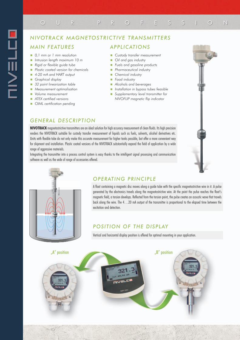
GENERAL DESCRIPT IONNIVOTRACK magnetostrictive transmitters are an ideal solution for high accuracy measurement of clean fluids. Its high precisionrenders the NIVOTRACK suitable for custody transfer measurement of liquids such as fuels, solvents, alcohol derivatives etc. Units with flexible tube do not only make this accurate measurement for higher tanks possible, but offer a more convenient wayfor shipment and installation. Plastic coated versions of the NIVOTRACK substantially expand the field of application by a widerange of aggressive materials.Integrating the transmitter into a process control system is easy thanks to the intelligent signal processing and communicationsoftware as well as the wide of range of accessories offered.
OPERATING PRINCIPLE
POSIT ION OF THE DISPLAY
A float containing a magnetic disc moves along a guide tube with the specific magnetostrictive wire in it. A pulsegenerated by the electronics travels along the magnetostrictive wire. At the point the pulse reaches the float’smagnetic field, a torsion develops. Reflected from the torsion point, the pulse creates an acoustic wave that travelsback along the wire. The 4…20 mA output of the transmitter is proportional to the elapsed time between theexcitation and detection.
Vertical and horizontal display position is offered for optimal mounting in your application.
„A” position „B” position
O U R P R O F E S S I O N
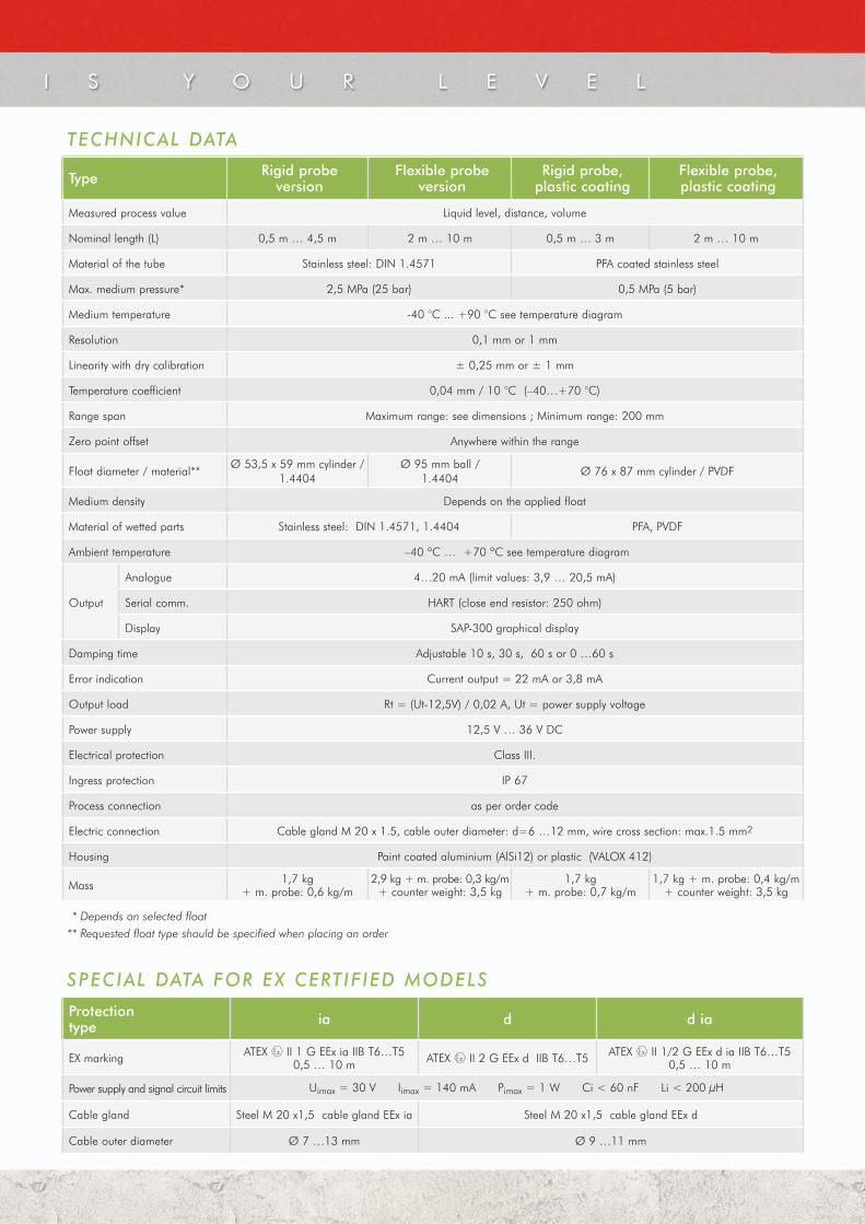
TECHNICAL DATA
Type Rigid probe version
Flexible probeversion
Rigid probe, plastic coating
Flexible probe,plastic coating
Measured process value Liquid level, distance, volume
Nominal length (L) 0,5 m … 4,5 m 2 m … 10 m 0,5 m … 3 m 2 m … 10 m
Material of the tube Stainless steel: DIN 1.4571 PFA coated stainless steel
Max. medium pressure* 2,5 MPa (25 bar) 0,5 MPa (5 bar)
Medium temperature -40 °C ... +90 °C see temperature diagram
Resolution 0,1 mm or 1 mm
Linearity with dry calibration ± 0,25 mm or ± 1 mm
Temperature coefficient 0,04 mm / 10 °C (–40…+70 °C)
Range span Maximum range: see dimensions ; Minimum range: 200 mm
Zero point offset Anywhere within the range
Float diameter / material**Ø 53,5 x 59 mm cylinder /
1.4404Ø 95 mm ball /
1.4404Ø 76 x 87 mm cylinder / PVDF
Medium density Depends on the applied float
Material of wetted parts Stainless steel: DIN 1.4571, 1.4404 PFA, PVDF
Ambient temperature –40 ºC … +70 ºC see temperature diagram
Output
Analogue 4…20 mA (limit values: 3,9 … 20,5 mA)
Serial comm. HART (close end resistor: 250 ohm)
Display SAP-300 graphical display
Damping time Adjustable 10 s, 30 s, 60 s or 0 …60 s
Error indication Current output = 22 mA or 3,8 mA
Output load Rt = (Ut-12,5V) / 0,02 A, Ut = power supply voltage
Power supply 12,5 V … 36 V DC
Electrical protection Class III.
Ingress protection IP 67
Process connection as per order code
Electric connection Cable gland M 20 x 1.5, cable outer diameter: d=6 …12 mm, wire cross section: max.1.5 mm2
Housing Paint coated aluminium (AlSi12) or plastic (VALOX 412)
Mass 1,7 kg + m. probe: 0,6 kg/m
2,9 kg + m. probe: 0,3 kg/m+ counter weight: 3,5 kg
1,7 kg + m. probe: 0,7 kg/m
1,7 kg + m. probe: 0,4 kg/m + counter weight: 3,5 kg
SPECIAL DATA FOR EX CERTIF IED MODELS
* Depends on selected float** Requested float type should be specified when placing an order
Protection type ia d d ia
EX marking ATEX II 1 G EEx ia IIB T6…T5 0,5 … 10 m ATEX II 2 G EEx d IIB T6…T5 ATEX II 1/2 G EEx d ia IIB T6…T5
0,5 … 10 m
Power supply and signal circuit limits Uimax = 30 V Iimax = 140 mA Pimax = 1 W Ci < 60 nF Li < 200 μH
Cable gland Steel M 20 x1,5 cable gland EEx ia Steel M 20 x1,5 cable gland EEx d
Cable outer diameter Ø 7 …13 mm Ø 9 …11 mm
I S Y O U R L E V E L
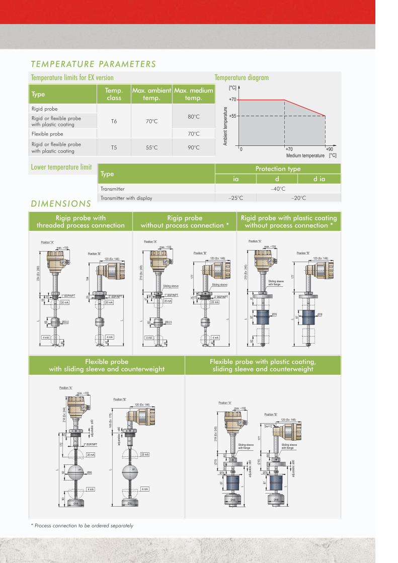
Temperature limits for EX version Temperature diagram
TEMPERATURE PARAMETERS
Type Temp.class
Max. ambienttemp.
Max. mediumtemp.
Rigid probe
T6 70°C80°CRigid or flexible probe
with plastic coating
Flexible probe 70°C
Rigid or flexible probe with plastic coating
T5 55°C 90°C
Lower temperature limit
Rigip probe withthreaded process connection
Rigip probe without process connection *
Rigid probe with plastic coatingwithout process connection *
Flexible probe with sliding sleeve and counterweight
Flexible probe with plastic coating,sliding sleeve and counterweight
* Process connection to be ordered separately
TypeProtection type
ia d d iaTransmitter –40°C
Transmitter with display –25°C –20°CDIMENSIONS

FLOATS
Type MBA-505-2M-200-00*
MBK-530-2M-400-00**
MBA-505-2M-900-00**
MGU-505-2M-200-00**
Dimensions
Medium density (min.) 0,85 0,55 0,4 0,7
Medium pressure 2,5 MPa (25 bar) 0,5 MPa (5 bar)
Material 1.4404 PVDF
* Designed for min. 2” process connection, only order with rigid probe ** Flange to be ordered separately
MULTICONT can handle a max. of 15 HART capable transmitters (4 Ex-version transmitters). The digital (HART) information is processed,displayed and if needed it can be transmitted via RS485 commu-nication line to a PC. Remote programming of the transmitters is also possible. Visualisation on PC can be accomplished with NIVISION process visualisation software.
RS485HART
The instrument with HART output can be connected to a PC using a SAT-304HART USB modem. Max. 15 normal (non Ex) instruments can be connected to a HART line. Measured values can be visualised and/or the instruments can be programmed via digital HART communication. Applicable software: EViewconfiguration software or NIVISION process visualization software.
NIVOTRACK IN SYSTEM WITH PC
NIVOTRACK IN A HARTMULTIDROP LOOP
WIRING
loop current measuring connector
1 4
U- U+
2 3
I- I+
Display moduleconnector
4-20 mA currentoutput and powersupply (HART)
PROCESS CONNECTION
Type Material Proc.Conn.
Dimensions
S (mm)
H (mm)
L (mm)
B (mm)
MBH-105-2M-300-00 1.4571 1” BSP 41 36 20 –
MBK-105-2M-300-00 1.4571 2” BSP 70 43 24 –
MBL-105-2M-300-00 1.4571 1” NPT 41 38 – 10
MBN-105-2M-300-00 1.4571 2” NPT 70 43 – 11
MGH-105-2M-300-00 PVDF 1” BSP 46 42 22 –
SAT 304HART modem
mt5
0s10
a060
1b
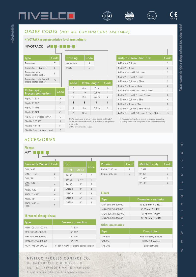
ORDER CODES (N OT A L L C O M B I N AT I O N S AVA I L A B L E )
NIVOTRACK magnetostrictive level transmitters
Output / Resolution / Ex Code
4-20 mA / 0,1 mm 1
4-20 mA / 1 mm 2
4-20 mA + HART / 0,1 mm 3
4-20 mA + HART / 1 mm 4
4-20 mA / 0,1 mm / EExia 5
4-20 mA / 1 mm / EExia 6
4-20 mA + HART / 0,1 mm / EExia 7
4-20 mA + HART / 1 mm / EExia 8
4-20 mA / 0,1 mm / EExd A
4-20 mA / 1 mm / EExd B
4-20 mA / 0,1 mm / EExd+EExia C
4-20 mA + HART / 0,1 mm / EExd+EExia D
Probe type / Process connection Code
Rigid / 1” BSP A
Rigid / 2” BSP C
Rigid / 1” NPT D
Rigid / 2” NPT G
Rigid / w/o process conn.4 U
Flexible / 2“ BSP K
Flexible / 2“ NPT N
Flexible / w/o process conn.5 Z
NIVOTRACK M – – 1
Type Code
Transmitter T
Transmitter + display2 B
Transmitter with plastic coated probe E
Transmitter + display withplastic coated probe2 G
Housing Code
Aluminium 5
Plastic3 6
1) The order code of an Ex version should end in „Ex”2) The position of the display (A or B) should be specifiedin the order3) Not available in Ex version
4) Threaded sliding sleeve should be ordered separately5) Sliding sleeve with flange should be ordered separately
Code Probe length Code
0 0 m 0 m 0
1 1 m 0,1 m 1
2 2 m 0,2 m 2
••••••
••••••
9 9 m 0,9 m 9
A 10 m
ACCESSORIES
Flanges
Pressure Code
PN16 / 150 psi 1
PN25 / 300 psi 2
Middle facility Code
1” BSP 2
2” BSP 3
1” NPT 5
2” NPT 6
MFT –
Standard / Material Code
DIN / A38 1
DIN / 1.4571 2
DIN / PP 3
DIN / A38 +,PTFE 4
ANSI / A38 5
ANSI / 1.4571 6
ANSI / PP 7
ANSI / A38 +PTFE 8
Type Process connection
MBH-105-2M-300-00 1” BSP
MBK-105-2M-300-00 2” BSP
MBL-105-2M-300-00 1” NPT
MBN-105-2M-300-00 2” NPT
MGH-105-2M-300-00 1” BSP / PVDF, for plastic coated version
SizeCode
DIN ANSI
DN50 1” 0
DN65 2 1/2” 1
DN80 3” 2
DN100 4” 3
DN125 5” 4
DN150 6” 5
DN200 8” 6
Threaded sliding sleeve
Floats
Type Diameter / Material
MBA-505-2M-200-00 Ø 53,5 mm / 1.4571
MBK-530-2M-400-00 Ø 95 mm / 1.4571
MGU-505-2M-200-00 Ø 76 mm / PVDF
MBA-505-2M-900-00 Ø 124 mm / 1.4571
Other accessories
Type Description
SAP-300 Plug-in display module
SAT-304 HART-USB modem
SAS-302 EView software
N I V E L C O P R O C E S S C O N T R O L C O .H - 1 0 4 3 B U D A P E S T , D U G O N I C S U . 1 1.
T E L . : ( 3 6 - 1 ) 8 8 9 - 0 1 0 0 u FA X : ( 3 6 - 1 ) 8 8 9 - 0 2 0 0E-mai l : sa les@nive lco.com h t tp://www.nive lco.com
Nive
lco re
serv
es th
e righ
t to c
hang
e tec
hnica
l data
with
out n
otice
!