NITROGEN PRO: ASSEMBLY GUIDE - Argon 18 · NITROGEN PRO: ASSEMBLY GUIDE ... bumps, cracks, paint...
42
NITROGEN PRO: ASSEMBLY GUIDE Valid for MY2016 Nitrogen Pro Revision 11.0 - 08-03-2016
Transcript of NITROGEN PRO: ASSEMBLY GUIDE - Argon 18 · NITROGEN PRO: ASSEMBLY GUIDE ... bumps, cracks, paint...

NITROGEN PRO: ASSEMBLY GUIDE
Valid for MY2016 Nitrogen Pro
Revision 11.0 - 08-03-2016

1. Frame Inspection . . . . . . . . . . . . . . . . . . . . . . . . . . . . . . . . . . . . . . . . 2
2. Frameset Parts . . . . . . . . . . . . . . . . . . . . . . . . . . . . . . . . . . . . . . . . . . . 3
3. Headset Installation . . . . . . . . . . . . . . . . . . . . . . . . . . . . . . . . . . . . . . 5
4. Stem/Handlebar Installation . . . . . . . . . . . . . . . . . . . . . . . . . . . . . . 8
5. Front Brake Installation. . . . . . . . . . . . . . . . . . . . . . . . . . . . . . . . . . 16
6. Rear Brake Installation . . . . . . . . . . . . . . . . . . . . . . . . . . . . . . . . . . 20
7. Cable Housing Installation . . . . . . . . . . . . . . . . . . . . . . . . . . . . . . 22
8. Electronic Drive-train Specification . . . . . . . . . . . . . . . . . . . . . .28
9. Seatpost Installation. . . . . . . . . . . . . . . . . . . . . . . . . . . . . . . . . . . . 32
10. Saddle Adjustment . . . . . . . . . . . . . . . . . . . . . . . . . . . . . . . . . . . . 33
11. Derailleur Hanger Adjustment. . . . . . . . . . . . . . . . . . . . . . . . . . 34
12. Frameset Parts Checklist . . . . . . . . . . . . . . . . . . . . . . . . . . . . . . . 36
For the warranty to be valid, the bicycle must be fully assembled by an authorized Argon 18 dealer. High end components, particularly carbon parts, need extra care when assembled. These components must be installed using a calibrated torque wrench to make sure every bolt is at the right torque setting to prevent damage.
NITROGEN PRO: Table of Contents
1
My Nitrogen Pro
Date of purchase:
Retailler:
Size:
Serial Number:

Parts installed on the frame Description Screw Tork Detail type Nm 1 Front derailleur hanger Screw (2) 3mm 4Nm Loctite 2 Rear derailleur hanger Screw (2) 3mm 4Nm Loctite 3 Bottle cage Screw (4) 4mm 3Nm Grease 4 Bottom bracket cable guide Screw 5mm 1.5Nm Grease
IMPORTANT:The following parts are assembled on the frame. When assembling the bike, you will need to adjust these parts according to their torque specifications.
NITROGEN PRO: 1. Frame Inspection
2
BEFORE ASSEMBLING YOUR NEW NITROGEN PRO, MAKE SURE THAT YOU HAVE ALL THE FOLLOWING:
1. Brakes and gears cables and housing set2: Frameset parts checklist (see p.36)3: Inspect the frame for cosmetic aspect (scratches, bumps, cracks, paint defect, etc.)4: For reference, check serial number and write it on p.15: All the necessary bolts (refer to Frameset Parts, p.3)6: For optimal shifting performance, use a dropout alignment gauge to make sure that the drive-side dropout is straight (p.35)

NITROGEN PRO: 2. Frameset Parts
Images are for reference only. Proportions are not accurate.Argon 18 reserves the right to modify/change parts of the frameset at any moment without prior notice.
*For more info please consult notice on Seatpost clamp dated 2016-06-09
16
17 18
3
3g
3c
3e
3h
3f
3d3b
3a
3i
20
15 4 514 13
109
678
2
17b
17f
17a
17g
17d
17e
17c
17h
17i
17h
17i
17h 18b
18f
18a
18g
18d
18e
18c
18h
18i
18h
18i
18h
19
21Brake & derailleurcable / housing kitJB527AR01, JD527AR01
12*11*
12*11*
running change
3

NITROGEN PRO: 2. Frameset Parts
AHB5000 (38cm, 40cm, 42cm, or 44cm)
Spacer 20mm
Stem A.03Large
Stem A.02Medium
Stem A.01Small
Elastic CoverLarge
Elastic CoverSmall
WasherM8
ScrewM8x50mm
ScrewM8x30mm
ScrewsM5x16mm
4
22
23 24 25 26 27 28 29 30 31 32
Frameset Handlebar Width Stem Size 20mmSize 38 40 42 44 Small Medium Large Spacer
X-Small
Small
Medium
Large
X-Large
Notes: 38cm Handlebar is only available aftermarket. If you wish to purchase the third non-included stem, you can do so by ordering it as a spare part

Install the 3D headset (16) according to the AERO Pressfit assembly guide. You can choose from 3 different heights: 25mm, 15mm or 0mm.
5
NITROGEN PRO: 3. Headset Installation
16
GREASE
GREASE
GREASE
GREASE

6
NITROGEN PRO: 3. Headset Installation
25mm
15mm
0mm
setup
setup
setup
5
34
1
1
1
5
34
5
34
5
6
7
2
6
2
7
8
6
5 5
Compressor
Top cap (including O-ring & seal)
Micro spacers
Compression ring
Bearing
3D bearing holder
Plastic sleeve (no need for 0mm setup)
Top cap for 0mm setup
1
2
3
4
5
6
7
8
head tube(bike)
head tube(bike)
head tube(bike)
To remove the 3D bearing holder, insert the Park Tool RT-1 and then tap it carefully until the spacer comes out.
1STEP
Inspect the bike’s head tube for any sharp edges and apply a small amount of grease.2
STEP
For the 25mm and 15mm setups, lightly grease thebottom section of the 3D bearing holder (6) and insert the plastic sleeve (7).3
STEP
Position the headset inside the head tube. Placethe top 3D assembly with the headset bearing inside(this will prevent the sleeve from getting damaged). Add the compression ring on top of the bearing, then add the press �t 3D system tool and softly press down the assembly until it bottoms out using a Bearing Cup Press (Park Tool HHP-2). Then, insert the bottom bearing (5), compression ring (4) micro spacers (3) and top cap (2), slide the fork and stem and measure the steerer length needed.
For the 0mm setup , do not use the plastic sleeve.Install the 3D bearing holder (6) with grease applieddirectly inside the frame.
4STEP
First, you must assess which setup suits your needs: 25mm, 15mm or 0mm.

7
NITROGEN PRO: 3. Headset Installation
Compressor
Top cap (including O-ring and seal)
Micro spacers
Compression ring
Bearing
3D bearing holder
Plastic sleeve (no need for 0mm setup)
Top cap for 0mm setup
1
2
3
4
4
5
5
6
6
7
7
8
Press Fit 3D system tool 1 1/4”
Bearing Cup Press (Park Tool HHP-2)
IMPORTANT: Use the Press Fit 3D system tool 1 1/2” with the Bearing Cup Press (ParkTool HHP-2) to avoid any damage on the bike frame.

8
NITROGEN PRO: 4. Stem/Handlebar Installation
Han
dleb
ar W
idth
(cm
)
Stems size (stems included)
38
40
42
44
S M L70mm 80mm *(110mm)
80mm 90mm *(100mm)
*(80mm) 90mm 100mm
*(90mm)
*Requires the purchase of an additional stem from the ones included in basic assembly.
100mm 110mm
20mm spacer
C O N F I G U R A T I O N M A T R I XC O N F I G U R A T I O N M A T R I X
If you wish to purchase the third non-included stem, you can do so by ordering it as a spare part.
Failure to use long screw when assembling bar with +20mm spacer of any configuration can lead to serious injury

9
NITROGEN PRO: 4. Stem/Handlebar Installation
1. Choose the desired stem length, bolt, and spacer needed (refer to the Product Matrix chart on p.X) – note that the bolt comes pre-coated with Loctite. In the event of assembling and disassembling, one drop of blue Loctite (#242 or #243) must be applied on the bolt threads.

10
NITROGEN PRO: 4. Stem/Handlebar Installation
2. Place the elastic cover on the stem and the spacer with the Argon 18 logo facing up.
3. Place the handlebar upside down on a clean rag.
4. With the correct spacer and stem length using a torque wrench, a ratchet extension, and a 6mm bit thread the bolt and spacer up to 40Nm.
5. For easier handling and to prevent damage to the handlebar we recommend holding it down firmly while tightening.
40Nm
IMPORTANT:If the appropriate torque (40Nm) is not reached and if Loctite is not applied the handlebar could loosen. Argon 18 cannot be held accountable if this is not measured.

11
NITROGEN PRO: 4. Stem/Handlebar Installation
Place the handlebar on the fork and secure the stem/combo with the two side bolts to 5Nm.
5Nm
5Nm
2-3mm
Note: When cutting the fork, allow 2mm or 3mm of additional space between the compressor cap and the fork in order to obtain sufficient compression of the headset.
GRIP PASTE
GRIP PASTE

NITROGEN PRO: 4. Stem/Handlebar Installation
1. Install the brake hood to the desired height and make a mark with a white pen.
2. Lower the shifter assembly.
Electronic ShiftingImportant: Always pass the electronic cables before the brake housing; the opposite would make it very difficult to get the electronic cables through after the brake housing.
12

NITROGEN PRO: 4. Stem/Handlebar Installation
3. Fish two cables inside the handlebar on each side.
4. Select the length of necessary housing and pass both at the same time.
13

NITROGEN PRO: 4. Stem/Handlebar Installation
5. Pass the brake and gear cables in the shifter body.
6. Connect cables to housing and put the levers back to the white mark on the handlebar.
14

NITROGEN PRO: 4. Stem/Handlebar Installation
Computer mount is compatible with any 2-screw computer mounting accessories.
Note: tighten to 3,5 Nm maximum.
15

16
NITROGEN PRO: 5. Front Brake Installation
Cable routing overview
Suggested lengths of the cable housing
housing/size
Front brake
Rear brake front section
Rear brake rear section
Front derailleur
Rear derailleur
40cm
30cm
20cm
110cm
185cm
45cm
35cm
20cm
110cm
190cm
50cm
40cm
20cm
120cm
195cm
55cm
45cm
25cm
125cm
200cm
XS S M L
It’s better to install cable housing before installing the bottom bracket and crankset.
FB
RB
FD
RD

NITROGEN PRO: 5. Front Brake Installation
17
Install the brakes as shown in the diagram.
8 Nm
8 Nm
GREASE
GREASE
5.10
5.4
5.5
5.3
5.7
5.6
5.1
5.2
LOCTITE
LOCTITE
GREASE
GREASE
NITROGEN PRO: 5. Front Brake Installation
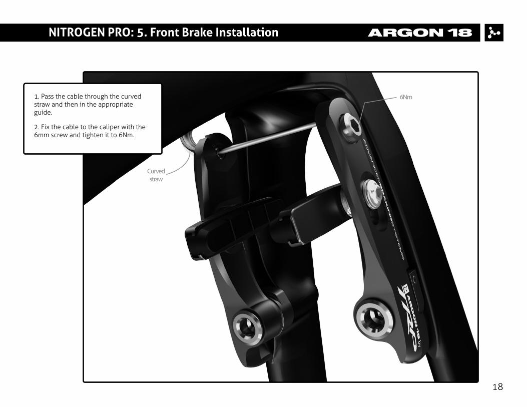
1. Pass the cable through the curved straw and then in the appropriate guide.
2. Fix the cable to the caliper with the 6mm screw and tighten it to 6Nm.
18
6Nm
Curvedstraw

NITROGEN PRO: 5. Brake Pad Spacing
IMPORTANT: If the brake bad spacing is too thick, the brake arm can rub on the frame down tube. Make sure the pad spacing is appropriate.
Adjust brake pads according to the width of your rims:
- You can configure the brake pad spacers with 1mm (17h), or 2mm (17i) depending of the rim width you are using.
19
Spacers required accordingto the rim widthRim width Spacer combinaison
19mm 2mm spacer(e.g.: Shimano C50)
24mm + 1mm spacer(e.g.: 808 clincher/Enve) (thin pad may be required)
17h
17i
17h
17i
NITROGEN PRO: 6. Rear Brake Installation
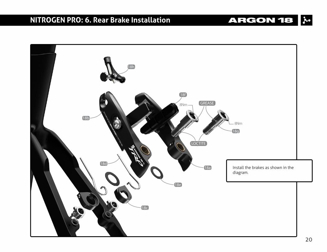
Install the brakes as shown in the diagram.
20
8Nm
8Nm
GREASE
outerside
18b
18h
18d
18e
18a
18g
18c
18f
LOCTITE

NITROGEN PRO: 6. Rear Brake Installation
1. Adjust brake pads according to the width of your rims:
2. Pass the cable through the cable guide. Make sure that the length of the cable housing is sufficient for the guide to remain horizontal as it can cause interference with the rear wheel tire.
3. Use the proper brake bad spacers depending on the width of your wheel rims.
4. Fix the cable to the caliper with the 6mm screw and tighten it to 6Nm.
21
6Nm
22
NITROGEN PRO: 7. Cable Housing Installation
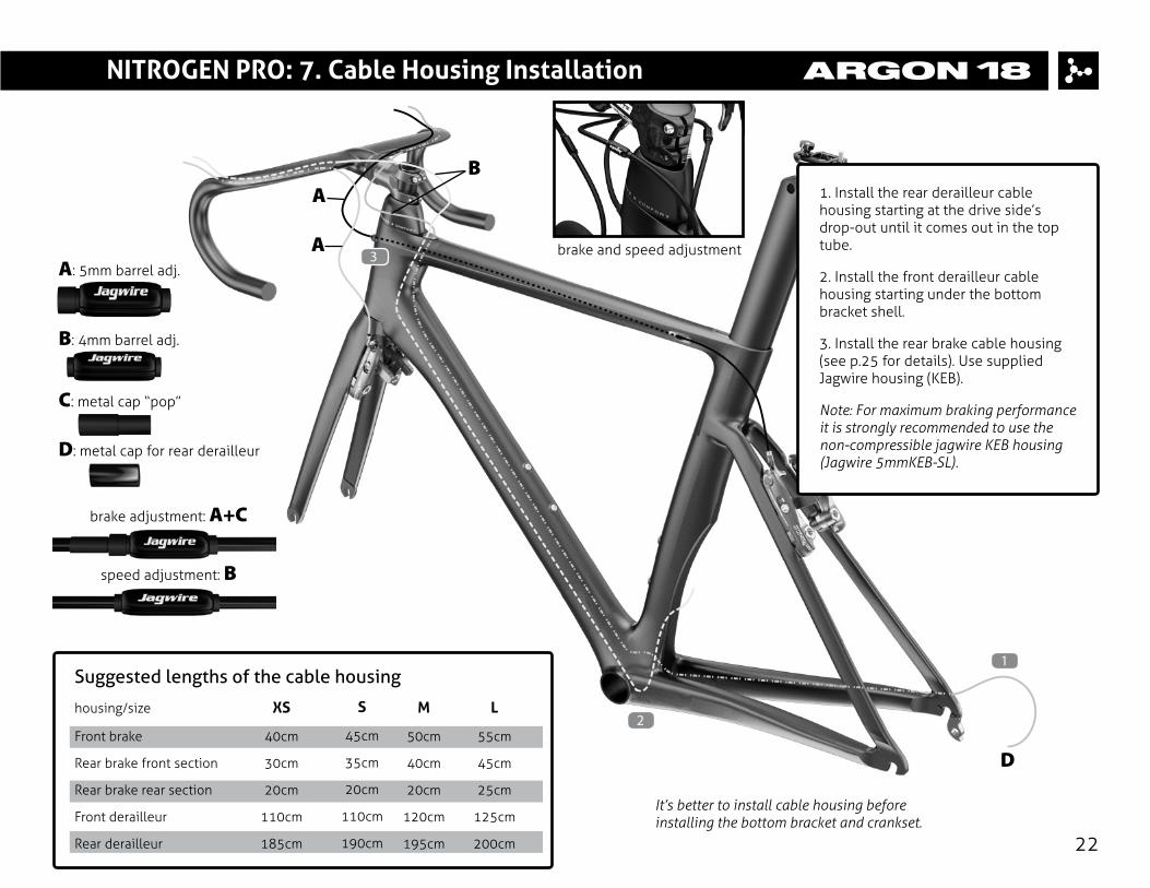
1. Install the rear derailleur cable housing starting at the drive side’s drop-out until it comes out in the top tube.
2. Install the front derailleur cable housing starting under the bottom bracket shell.
3. Install the rear brake cable housing (see p.25 for details). Use supplied Jagwire housing (KEB).
Note: For maximum braking performance it is strongly recommended to use the non-compressible jagwire KEB housing (Jagwire 5mmKEB-SL).
Suggested lengths of the cable housing
housing/size
Front brake
Rear brake front section
Rear brake rear section
Front derailleur
Rear derailleur
40cm
30cm
20cm
110cm
185cm
45cm
35cm
20cm
110cm
190cm
50cm
40cm
20cm
120cm
195cm
55cm
45cm
25cm
125cm
200cm
XS S M L2
1
3A: 5mm barrel adj.
brake and speed adjustment
B: 4mm barrel adj.
C: metal cap “pop”
D: metal cap for rear derailleur
D
B
brake adjustment: A+C
speed adjustment: B
It’s better to install cable housing before installing the bottom bracket and crankset.
A
A

Note: The front brake cable guide (17h) should be front-oriented to ensure good rotation of the handlebar.
23
NITROGEN PRO: 7. Cable Housing Installation
Front brake cable guide17h

24
NITROGEN PRO: 7. Cable Housing Installation
Front brake
Pass the cable through the cable guide (17h).
Create a “hook” with the cable; it will be easier to pass it inside the retainer nut.
6Nm

25
NITROGEN PRO: 7. Cable Housing Installation
Rear brake
Remove the 2 cable stopper (on the head tube and near the seat collar).
Font section: Measure the necessary cable housing to ensure proper rotation of the handlebar. Insert the “KEB” cable housing and the cable trough the top tube.
Rear section: With a magnet, get the rear brake cable out of the frame, and pass it through the rear cable stopper. Mesure the “KEB” rear housing correctly to avoid interference with the rider’s left leg.
KEB cable housing
45

Note: It’s better to install the cable housing before installing the bottom bracket and crankset.
Rear derailleur: Pass the cable housing inside the frame starting at the rear derailleur hanger until it comes out the top tube.
Front derailleur: Remove the cable guide (9) under the bottom bracket. Pass the cable housing inside the downtube until it comes out the top tube.
Add a plastic cap at the end of the housing, pass the rear derailleur cable inside the housing and fix the cable guide under the bottom bracket with the 5mm screw (1.5 Nm).
For a Di2 configuration, use the bottom bracket dedicated cover (10) for electric shifting.
26
NITROGEN PRO: 7. Cable Housing Installation
9
10
1.5Nm
5mm

27
NITROGEN PRO: 7. Cable Housing Installation
19
Use the provided grommet (19) to correctly set the rear derailleur cable housing in the chainstay (mechanical drive-train only).
19

28
NITROGEN PRO: 8. Electronic Drive-train Specification
The Di2 cable routing can be achieved easily using this simple trick: use a gear cable and a metal cable end to fix the Di2 cable. For more information on Shimano Di2 electronic system installation, go to: si.shimano.com.

29
NITROGEN PRO: 8. Electronic Drive-train Specification
Use the proper grommet on the top tube to fix the cable correctly (depending if you use electronic shifting or mechanical drive-train).
15 14

30
NITROGEN PRO: 8. Electronic Drive-train Specification
When using an electronic drive-train, use the grommet (13) to fix the front derailleur cable.13

31
NITROGEN PRO: 8. Electronic Drive-train Specification
The Di2 battery is hidden in the seatpost; use the Di2 battery holder (2o) to fix the battery correctly. Apply a slight amount of grease on both parts.
20
GREASE
CARBON FIBER ASSEMBLY
COMPOSITE
NITROGEN PRO: 9. Seatpost Installation
32
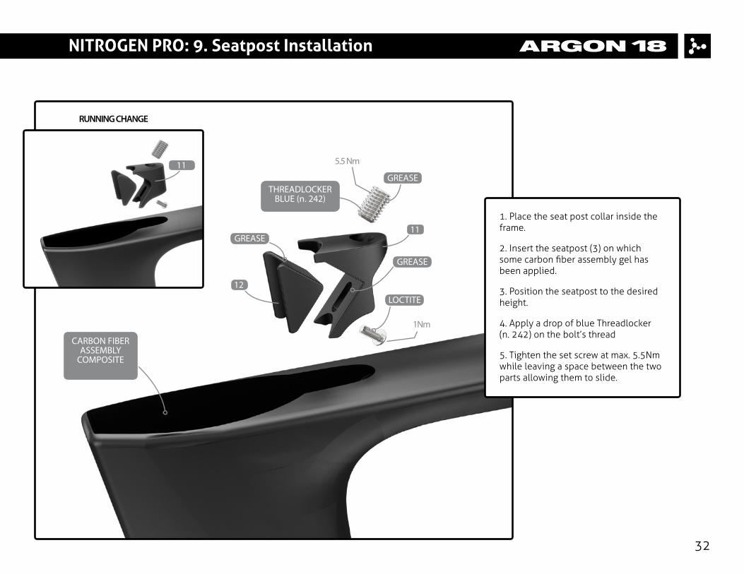
1. Place the seat post collar inside the frame.
2. Insert the seatpost (3) on which some carbon fiber assembly gel has been applied.
3. Position the seatpost to the desired height.
4. Apply a drop of blue Threadlocker (n. 242) on the bolt’s thread
5. Tighten the set screw at max. 5.5Nm while leaving a space between the two parts allowing them to slide.
GREASE
GREASE
THREADLOCKER BLUE (n. 242)
LOCTITE
GREASE
CARBON FIBER ASSEMBLY
COMPOSITE
5.5 Nm
1Nm
11
RUNNING CHANGE
11
12

NITROGEN PRO: 10. Saddle Adjustment
1. Install the saddle on the rocker (3b) and tighten the rail clamp (3c) up to 6Nm using the half-moon bolt (3i).
2. Adjust the angle and the offset of the saddle by hand tightening the thumb screw (3h).
3. The rocker (3d) can be flipped to change the saddle offset (+ / - 5mm).
33
3h
3d
3c
3i
6Nm
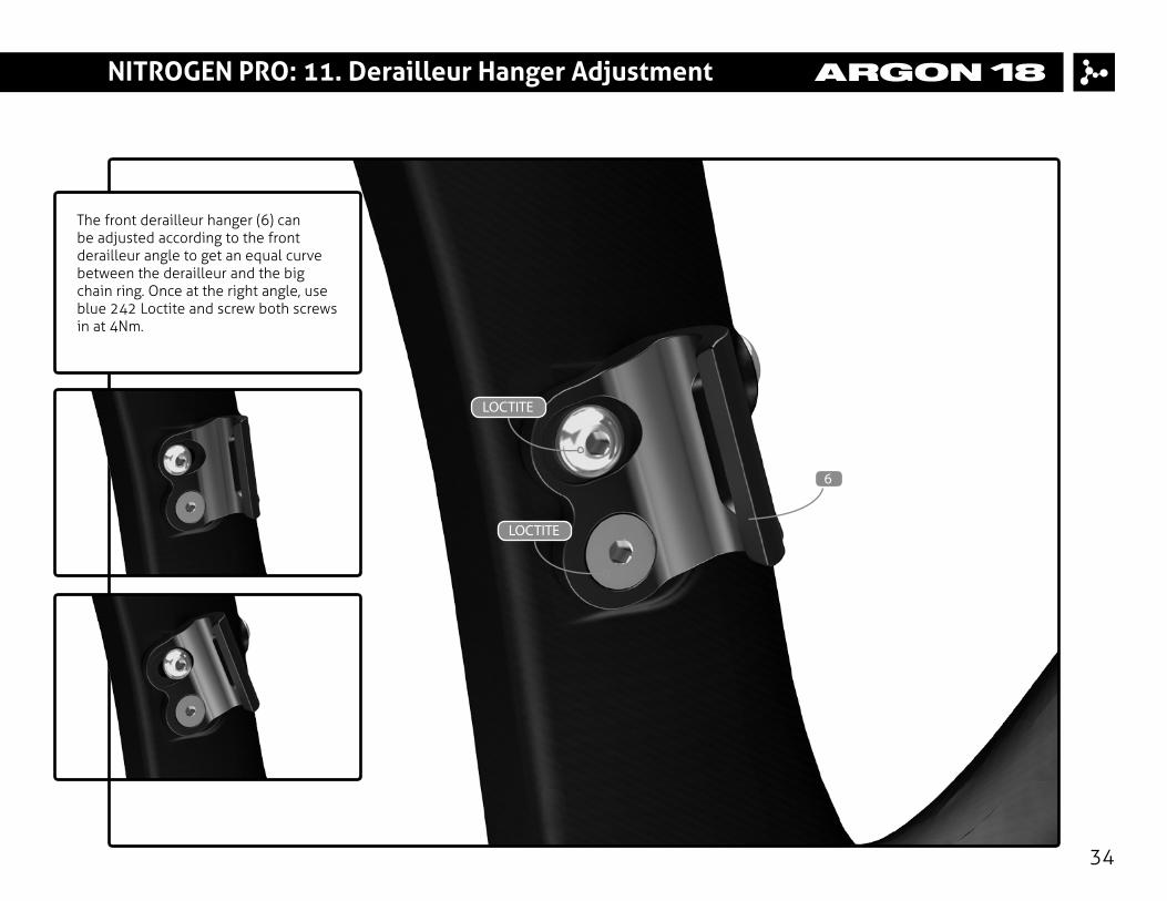
NITROGEN PRO: 11. Derailleur Hanger Adjustment
The front derailleur hanger (6) can be adjusted according to the front derailleur angle to get an equal curve between the derailleur and the big chain ring. Once at the right angle, use blue 242 Loctite and screw both screws in at 4Nm.
34
LOCTITE
LOCTITE
6

NITROGEN PRO: 11. Derailleur Hanger Adjustment
35
1. Ensure that the dropout is aligned.
2. Use Derailleur Hanger Alignment Gauge like Park Tool Item # DAG-2.
For any assistance, visit Park Tool’s website:parktool.com/product/derailleur-hanger-align-ment-gauge-dag-2
4Nm
7

NITROGEN PRO: 12. Frameset Parts Checklist
36
No. Name A18 SKU# Qty
# Frameset Parts
# Seat post with the following parts assembled
1 Nitrogen Pro MY2016 Frame 12 Nitrogen Pro MY2016 Fork FK.NITPRO.230A 1
3 Nitrogen pro seat post (ASP-5100) SP.NITPRO.230A 1 3a AG-SP-02 carbon part 13b Lower Rail Clamp 13c Upper Rail Clamp 13d Half Moon Nut M6 13e Half Moon Nut M5 13f Half Moon Bolt 13g Spherical Washer M5 13h M6 Thumbscrew 13i M5x40mm socket head 1

NITROGEN PRO: 12. Frameset Parts Checklist
37
No. Name A18 SKU# Qty
# Frame related parts already installed
4 Head tube brake cable stopper 38878 1 5 Top tube brake cable stopper 38879 16 Front derailleur hanger with screws 38882 17 Rear derailleur hanger with Flat Head screws (M3*8mm) 38883 18 Water bottle screw 38884 49 BB cable guide with Round Head Philips screws (M5*10mm) 38885 110 BB cover for elec. shifter with Round Head Philips screws (M5*10mm) 38260 1
# Seat collar
11 Seat collar base with screw M8x12mmF 80375, 80478 112 Seat collar wedge with screw M3x8mmB 80374, 80477 1
NITROGEN PRO: 12. Frameset Parts Checklist
38
No. Name A18 SKU# Qty
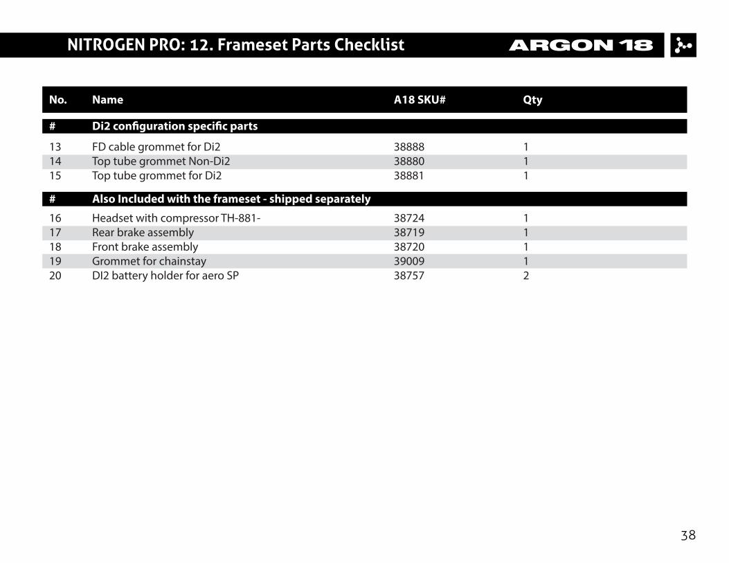
# Di2 con�guration speci�c parts
13 FD cable grommet for Di2 38888 114 Top tube grommet Non-Di2 38880 115 Top tube grommet for Di2 38881 1
# Also Included with the frameset - shipped separately
16 Headset with compressor TH-881- 38724 117 Rear brake assembly 38719 118 Front brake assembly 38720 119 Grommet for chainstay 39009 120 DI2 battery holder for aero SP 38757 2
NITROGEN PRO: 12. Frameset Parts Checklist
39
No. Name A18 SKU# Qty
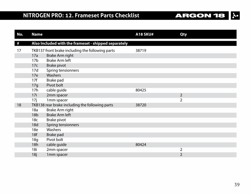
# Also Included with the frameset - shipped separately
17 TKB137 front brake including the following parts 38719 17a Brake Arm right 17b Brake Arm left 17c Brake pivot 17d Spring tensionners 17e Washers 17f Brake pad 17g Pivot bolt 17h cable guide 80425 17i 2mm spacer 2 17j 1mm spacer 2 18 TKB138 rear brake including the following parts 38720 18a Brake Arm right 18b Brake Arm left 18c Brake pivot 18d Spring tensionners 18e Washers 18f Brake pad 18g Pivot bolt 18h cable guide 80424 18i 2mm spacer 2 18j 1mm spacer 2
NITROGEN PRO: 12. Frameset Parts Checklist
40
No. Name A18 SKU# Qty
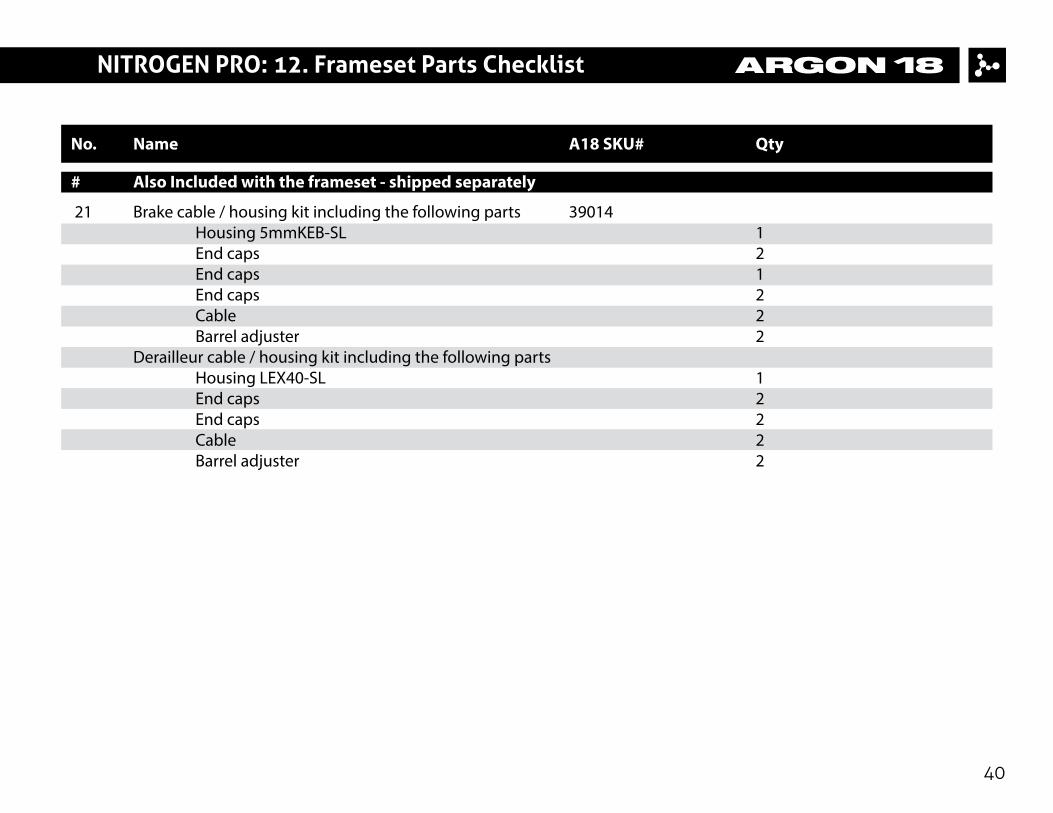
# Also Included with the frameset - shipped separately
21 Brake cable / housing kit including the following parts 39014 Housing 5mmKEB-SL 1 End caps 2 End caps 1 End caps 2 Cable 2 Barrel adjuster 2 Derailleur cable / housing kit including the following parts Housing LEX40-SL 1 End caps 2 End caps 2 Cable 2 Barrel adjuster 2

NITROGEN PRO: 12. Frameset Parts Checklist
41
No. Name A18 SKU# Qty
# AHB5000 Handlebar parts
22 AHB5000 - 38cm 80073 1 AHB5000 - 40cm 80074 1 AHB5000 - 42cm 80075 1 AHB5000 - 44cm 80076 123 Washer M8 80034 124 Screw M8x50mm 80030 125 Screw M8x30mm 80029 126 Elastic Cover Small 80162 127 Elastic Cover Large 80163 128 Stem Spacer 20mm 80104 129 Screw M5x16mm 80028 230 Stem A.03 Large 80105 131 Stem A.02 Medium 80106 132 Stem A.01 Small 80107 1