Nitrogen generator Laser Cut - claind.it · Nitrogen generator Laser Cut 3 1. Introduction This...
43
User’s manual Nitrogen generator Laser Cut
-
Upload
vuongkhanh -
Category
Documents
-
view
227 -
download
1
Transcript of Nitrogen generator Laser Cut - claind.it · Nitrogen generator Laser Cut 3 1. Introduction This...

User’s manual
Nitrogen generatorLaser Cut
2
Table of contents
1. Introduction 3
2. Safety 4
3. Description of the generator 6
4. Installation 10
5. Operating instructions 16
6. Maintenance 30
7. Troubleshooting 33
8. Technical specifications 37
9. Declaration of conformity 40
10. Notes 42

Nitrogen generator Laser Cut
3
1. Introduction
This document is aimed at the User of a CLAIND nitrogen generator model LA-SER CUT, and provides all information regarding use and maintenance. For moredetailed information on individual components, consult the relative instructionmanuals.
It is presumed that the manual user is experienced in the use of pneumatic com-ponents, and in particular is aware of all safety aspects linked to the use of com-pressed air and nitrogen.The instruction manuals of the various system components are enclosed, to-gether with the respective certificates of conformity with the applicable safetydirectives.
The margin of the manual text contains the following symbols, indicating:
m compulsory safety standards to be observed
c electrical hazard
e recommendations and important information
It is strongly recommended to carefully read all safety warnings (par. 2.1.) be-fore carrying out any operation on the generator.

Safety
4
2. Safety
The nitrogen generator must be used in observance of the instructions in thisbooklet. Failure to observe these instructions will render the guarantee null andvoid and release CLAIND from all liability for direct or indirect damage or physicalinjury.
2.1. Warnings
m The manual user is required to be an expert in handling pneumaticcomponents and fully aware of all safety aspects linked to the use ofpressure gas and the risks associated with the use of nitrogen (risk ofasphyxia).
m Never release nitrogen into a closed environment with inadequateventilation: risk of fatal injury by asphyxia.
m Never disconnect any pneumatic couplings before ensuring that therelative line is depressurised.
m Only skilled personnel must make inspections and repairs. CLAIND de-nies all liability for damage caused by improper use of the system.Always contact the Technical Assistance services before performingwork on the system.
m The generator contains components that require connection to theelectrical mains. Never perform maintenance or repairs when the sy-stem is connected to the electrical mains: risk of fatal injury by electro-cution.
m The system must be placed away from sources of heat.
m The system must not be placed in areas subject to the accumulation ofwater.
m The system must not be exposed to rain or wind.

Nitrogen generator Laser Cut
5
2.2. Safety devices
EMERGENCY PUSHBUTTON: enables immediate shutdown of the generator,cutting of electrical power supply to the actuators.
MAXIMUM PRESSURE: the safety valves (named SAF01, SAF02, SAF03,SAF04, SAF05, SAF06 -only for Model 450- and SAF07) prevent pressure in thevarious sections of the generator from reaching hazardous values.
m The safety valves are set to correct values and must not be tamperedwith under any circumstances. In addition, they should be checked pe-riodically according to local safety rules.
2.3. Technical assistance
The CLAIND technical assistance can be contacted as follows:Tel. ++39 0344 56603Fax ++39 0344 56627e-mail: [email protected]:filling the form in the website www.claind.it at the “Service” section

Description of the generator
6
3. Description of the generator
The Laser Cut nitrogen generator (see element B in the figure) enables the pro-duction of nitrogen at high pressure (up to 200 bar -20 MPa- or 300 bar -30MPa-) if suitably powered with compressed air.The system therefore requires, in addition to the nitrogen generator (B), a sec-tion for the generation of compressed air (A) and a section for storage of thehigh pressure nitrogen (C).Normally the compressed air section (A) comprises the following elements, sizedaccordingly: compressor, drier, filter pack, storage tank.Normally the nitrogen storage section (C) comprises one or more cylinder packs,sized accordingly. Neither the compressed air section (A) nor high pressure nitrogen storage sec-tion (C) are described in this manual.
Sia
la
sezione
aria
comp

Nitrogen generator Laser Cut
7
3.1. Nitrogen generator operating principle
The compressed air on inlet to the generator alternately feeds two columns con-taining a special molecular sieves (CMS) which separates the oxygen and nitro-gen using PSA (Pressure Swing Adsorption) technology.The nitrogen produced is first stored in a LOW PRESSURE NITROGEN TANK at amaximum pressure of 10 bar (1.0 MPa) to then be compressed to the requiredpressure (max 200bar -20MPa- or 300 bar -30MPa-) by means of the multi-stageHIGH PRESSURE NITROGEN COMPRESSOR. The generator control system manages correct operation (activation of valves,setting to stand-by pressure values, nitrogen compressor start-up and shu-tdown, purity readings of nitrogen produced etc.). For further information on operation of the generator, refer to the flow diagram.

Description of the generator
8
3.2. Generator components
3.2.1. Front viewA. MAIN SWITCHB. TOUCH SCREEN: operator interface; enables the display and entry of
operating parametersC. EMERGENCY PUSHBUTTOND. CMS COLUMNS: carbon molecular sieves E. LOW PRESSURE NITROGEN TANKF. LP BUFFER: compressor supply tankG. HIGH PRESSURE NITROGEN COMPRESSOR: multi-stage compressor for
nitrogen

Nitrogen generator Laser Cut
9
3.2.2. Rear viewH. ELECTRIC POWER: routing for electric power cablesI. AIR: pneumatic connection (G 3/4” female) for compressed air lineJ. NITROGEN OUTLET HIGH PRESSURE: pneumatic connection (1/4” G Female) for
high pressure nitrogen line - Max 200 bar (20MPa) or 300 bar (30MPa) according to model -
K. AIR CMS: pneumatic connection for the air delivery from main module to CMS module
L. N2 CMS: pneumatic connection for the nitrogen return from CMS module to main module
M. OUTLET NITROGEN LOW PRESSURE: pneumatic connection (G 3/4” female) for an optional nitrogen low pressure line
N. V001: pneumatic connection to the PNV01 valveV002: pneumatic connection to the PNV02 valveV003: pneumatic connection to the PNV03 valveV004: pneumatic connection to the PNV04 valveV005: pneumatic connection to the PNV05 valveV006: pneumatic connection to the PNV06 valve
O. DRAIN: Drain of exhaust gases from the compressor

Installation
10
4. Installation
4.1. Installation area requirements
4.1.1. Humidity and dustTo avoid risks of damage to electronic components, install the generator in anenvironment subject to limited relative humidity and low concentrations of dust.The generator must also be protected against drips, rain and wind.
4.1.2. TemperatureThe ambient temperature in the generator installation area must be between5°C and 40°C. Install away from heat sources. Avoid direct exposure to sunlight.
4.1.3. PositioningWhen choosing the installation area for the generator, as well as the dimensionsand the weight of the unit, take into account the following.MAIN MODULE:
• leave a clear space of at least 1 metre from the right-hand side to enable correctintake of cooling air;
• leave a clear space of at least 1 metre on the rear side of the main module toenable correct outlet of spent cooling air;
• leave a clear space in front of the unit to enable easy access by the operator tothe control panel and to facilitate panel opening. CMS MODULE:
• leave a clearance of 45cm between the main module left side and the CMS mo-dule right side to allow their pneumatic connection;
• leave a clearance of 60cm at the rear side to allow maintenance operations.
Nitrogen generator Laser Cut
11
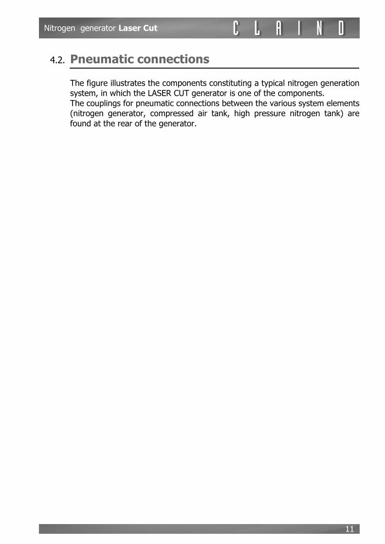
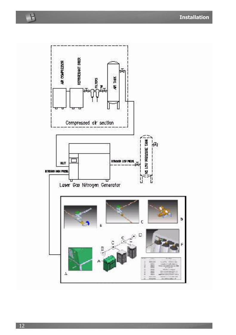
4.2. Pneumatic connections
The figure illustrates the components constituting a typical nitrogen generationsystem, in which the LASER CUT generator is one of the components. The couplings for pneumatic connections between the various system elements(nitrogen generator, compressed air tank, high pressure nitrogen tank) arefound at the rear of the generator.
Installation
12

Nitrogen generator Laser Cut
13
4.2.1. Air inletThe properties of the compressed air on inlet play an important role with regardto the performance and lifetime of the nitrogen generator. As well as the minimum flow rate requirements (outlined in the paragraph 8 Te-chnical Specifications) the compressed air used should be of a quality that meetsthe following specifications (ISO 8573-1; class 1-4-1):Dew point:< 3° CMaximum oil concentration:< 0.01 mg/m3Maximum particle concentration (diameter 0,1 m)< 0.1 mg/m3
e If a lower quality of compressed air is used, this could cause irreversible damageto the generator. In this case, Claind denies all liability for damages and any co-sts for repairs will be charged to the client
e For optimal operation of the nitrogen generator, the pressure of the compressedair on inlet to the unit should never fall below 8.5bar
e The purity of the nitrogen produced is reduced when the air pressure on inletlowers. Therefore the installation of a compressed air reserve tank is recommen-ded, sized accordingly. In the event of any doubt or uncertainty with regard tothe above, contact Claind for advice on the type of compressed air system (com-pressor, drier, filters, tank) most suited to the specific application
CONNECTION • Locate the air coupling (G 3/4” female), marked “AIR” at the rear of the gene-
rator• connect the compressed air tank to the generator (the piping must be adequate
to air pressure and flow rate)
4.2.2. Nitrogen outlet
The high pressure nitrogen produced by the generator must be conveyed to asuitable storage system, used to absorb peaks in consumption and to compen-sate for technical shutdown times of the nitrogen compressor.
m The nitrogen storage system elements (i.e. the components installeddownline of the NITROGEN outlet of the generator) must be suitablesized for the maximum admissible pressure of the nitrogen generator
Normally, the storage system comprises one or more “cylinder racks” equippedwith suitable accessories (“ramps” on inlet and outlet, multi-stage pressure re-ducer on outlet etc.)
PRESSURE: the maximum admissible pressure is indicated at the rear of the ge-nerator (205 or 305 bar)

Installation
14
FLOW RATE: The nitrogen flow rate depends on the required model and purity.For details, refer to paragraph 8 Technical Specifications
PURITY: The generator produces nitrogen at a set purity level (between 99,99%and 99,999%) according to the user requirements at the time of the purchaseorder. The generator is set at the Claind factory for this purity level and cannotbe modified by the User at a different level without the intervention of a qualifiedClaind technician.
CONNECTION • Locate the coupling (1/4” G Female) marked “OUTLET NITROGEN HIGH PRES-
SURE” at the rear of the generator• connect the high pressure hose using couplings suited to the nominal pressure
of the generator
m Secure the flexible hoses with safety wires
e the high pressure installation kit provided by Claind is sized for a maximum ad-missible pressure at 205 bar

Nitrogen generator Laser Cut
15
4.3. Electrical power supply
e The power line cable is not supplied with the generator and should be thereforeinstalled by the User.
e The safety devices for the power line (Switch and Fuses) are not supplied withthe generator and should be therefore installed by the User
c For the installation of the electrical safety device (switch and fuses)and the correct sizing of the power line cables, see the followingdrawing
Operating instructions
16
5. Operating instructions
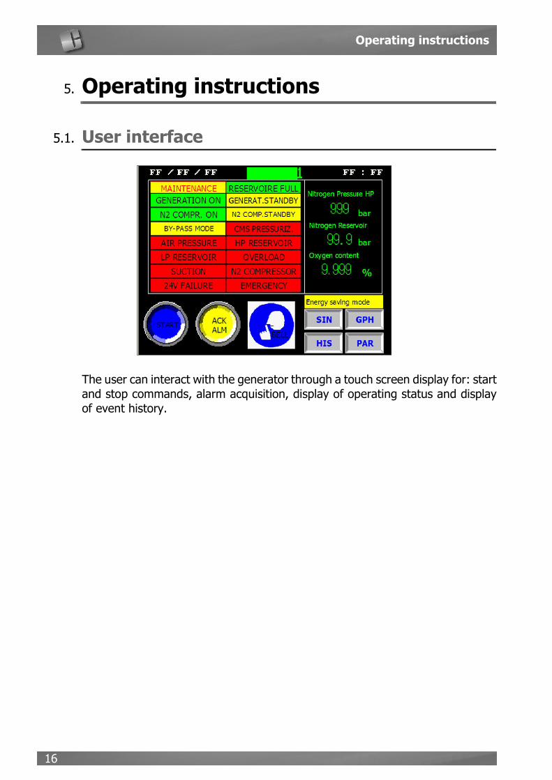
5.1. User interface
The user can interact with the generator through a touch screen display for: startand stop commands, alarm acquisition, display of operating status and displayof event history.

Nitrogen generator Laser Cut
17
5.1.1. MenuThis diagram illustrates the screens accessible by the user and keys for accessto the various pages
e to press the buttons on the touch screen please never use sharp objects, whichmay cause irreparable damage to the screen

Operating instructions
18
5.1.2. Introduction page (page00)
This page is displayed on start-up of the generator. It enables access to the fol-lowing pages:
• OPTIONS 1 (page 08), by pressing OPTIONS• SYSTEM DATA (page09), by pressing SYSTEM DATA• CONTROL PANEL (page 03), by pressing ESC
5.1.3. Options (page08)
The relative icons on this page can be pressed to enable entry of the language.
e the languages currently available are Italian and English

Nitrogen generator Laser Cut
19
Starting from this page it’s possible to:• return to the INTRODUCTION PAGE (page00), press ESC• enable settings for the “Energy saving mode” pressing “Energy saving mode
configuration”
5.1.4. System data (page09)
In this page it’s possible to enable settings of the AUTOMATIC START, that is theactivation of automatic restart after shutdown of the generator due to temporarypower failure.
e this function, if activated, enables nitrogen production to be resumed automati-cally following a power failure
This page also displays a number of important counters for generator operation:• number of motor starts• nitrogen compressor operating hours• general operating hours • time remaining for generator restart

Operating instructions
20
5.1.5. Operator panel (page03)
This is the most important screen page. It enables access to the buttons START, STOP and ACK ALM (alarm acquisition),displayed only when enabled in the various operation phases.This page also displays messages regarding the generator operating status.The right section also displays the main process values (nitrogen pressure andpurity).
This page also enables access to the following pages:• LP SYNOPTIC (page 10), by pressing SIN• LP GRAPH (page 22), by pressing GPH• HISTORY (page 19), by pressing HIS• INTRODUCTION PAGE (page00) by pressing PAR
Nitrogen generator Laser Cut
21
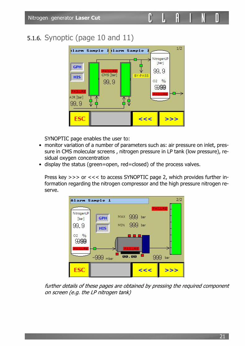
5.1.6. Synoptic (page 10 and 11)
SYNOPTIC page enables the user to:• monitor variation of a number of parameters such as: air pressure on inlet, pres-
sure in CMS molecular screens , nitrogen pressure in LP tank (low pressure), re-sidual oxygen concentration
• display the status (green=open, red=closed) of the process valves.
Press key >>> or <<< to access SYNOPTIC page 2, which provides further in-formation regarding the nitrogen compressor and the high pressure nitrogen re-serve.
e further details of these pages are obtained by pressing the required componenton screen (e.g. the LP nitrogen tank)

Operating instructions
22
5.1.7. History (page19)
The HISTORY page displays the last relevant events during generator operation(alarms, important status changes). The button DEL HIS allows to clear the page.
5.1.8. Graph (page22)
The GRAPH page displays the trends of pressure in the low pressure nitrogentank over the last 10 minutes.The keys at the lower section of the screen enables the user to interrupt, restartor delete recording of these data.

Nitrogen generator Laser Cut
23
5.2. Generator start-up
To switch on the generator, set the main switch A to ON on the front panel ofthe generator.The touch screen initially displays the CLAIND logo and after a few secondsshows the OPERATOR PANEL (page03) with the message “WAIT” scrollingacross the screen.At the end of the wait time (100 seconds), the message “GENERATOR READY”is displayed with the START button.
5.3. Entry of the language and (optional) of the “Energy saving mode”
• From the OPERATOR PANEL press the button “PAR” for access to the INTRO-DUCTION PAGE (page00), to set the required language
5.3.1. “Energy saving mode” settingsThe Energy saving mode is used to define two ways of working of the Laser Cutgenerator. Setting two different high pressure stand-by thresholds is possible toproduce nitrogen when electric power costs less, instead when it’s more expen-sive the generator is stopped till when the high pressure is under the “MIN - HPreservoir pressure - Energy saving mode” threshold.
5.3.1.1.“Energy saving mode enabling”
Starting from the “Operator panel” page, go to the “Presentation” page clickingon the “PAR” key:

Operating instructions
24
From the “Presentation” page go to the “Options 1” page clicking on the “OP-TIONS” key:
In the “OPTIONS 1” page is possible to use the “Energy saving mode” key toenable or to disable the “Energy saving mode”. The current status is representedby the white lable showing “Energy saving mode ON” or “Energy saving modeOFF”, even on the key there is a label showing the option status “ON” / “OFF”.
Nitrogen generator Laser Cut
25
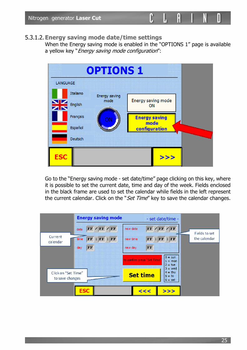
5.3.1.2.Energy saving mode date/time settingsWhen the Energy saving mode is enabled in the “OPTIONS 1” page is availablea yellow key “Energy saving mode configuration”:
Go to the “Energy saving mode - set date/time” page clicking on this key, whereit is possible to set the current date, time and day of the week. Fields enclosedin the black frame are used to set the calendar while fields in the left representthe current calendar. Click on the “Set Time” key to save the calendar changes.

Operating instructions
26
Go the ”Energy saving mode - set times” clicking on the scroll key at the bottomright of the page. Here it’s possible to set for which day and at what time to usethe Energy saving mode choosing one or more days by clicking on the keyshowing the name of the day. Activating the Energy saving mode for a day itslabel becomes green and appear the fileds to set the on and off times:
For every day is possible to set time slot with this range; from “00:00” to“23:59”, so for example to set the Energy saving mode from Thursday at 17:00(05:00 p.m.) to Friday at 06:00 (06:00 a.m.) make this settings:

Nitrogen generator Laser Cut
27
5.3.1.3.Stand by threshold settings: Go to the “OPTIONS 2” page clicking on the scroll key at the bottom right of thepage. If the Energy saving mode is enabled, in this page is possible to set twodifferent stand-by threshold, one for the Energy saving mode operation and theother for normal operation:
The “MIN” threshold represent the minimum high pressure value under whichthe generator restart, while the “MAX” threshold represent the high pressure va-lue at which the generator is on stand-by.
5.3.1.4. Energy saving mode indicator:In the “Operator Panel” page there is a blinking icon showing this message:“Energy saving mode”. This icon appears when the generator is working in Ener-gy saving mode.
5.3.1.5.

Operating instructions
28
5.4. Nitrogen production
m Please ensure the electrical connection is made correctly (and in par-ticular the direction of compressor rotation*) as well as the pneumaticconnection of the compressed air line and the high pressure nitrogenline. Ensure that the high pressure nitrogen hoses are fitted with sa-fety valves.* in case of wrong rotation direction, an alarm OIL PRESSURE or MOTOR ROTA-TION will appear: see chapter 7.1.5 for more details
Enter the CONTROL PAGE (page03) and press the START button.During nitrogen production, the molecular sieves (CMS) and nitrogen compres-sor operate more or less continuously on the basis of the utility nitrogen requi-rements.The pages HISTORY, GRAPH AND SYNOPTIC can be displayed but we recom-mend returning to the OPERATOR PANEL as this provides more information ongenerator operation. This page also enables the user to stop production (STOP)or acknowledge alarms (ACK ALM).
5.5. Repeating alarm and buzzer signals
There’s the possibility to repeat the alarm and buzzer signals as shown below:
1. in case of alarm, it’s enabled the power relay, whose contacts work as follows:
2. in case of alarm, it’s enabled the buzzer on the display-interface. It’s possible to add an external sonic signal, using the two power relay contacts11KA2as shown below:
It’s possible to silence the external sonic signal directly from the display or re-motely through a switch connected to 6 and + X1 terminals.
StatusWorking
conditionsClosed contact
Open contact
Terminal board X1
Not working No alarm 11,12 11,14 22,23
Working Alarm 11,14 11,12 22,24
StatusWorking
conditionsClosed contact
Open contact
Terminal board X4
Not working Buzzer OFF 11,12 11,14 15,16
Working Buzzer ON 11,14 11,12 14,16

Nitrogen generator Laser Cut
29
5.6. Stop the generator
In the event of an emergency, press the emergency button on the front panel.
m generation shutdown in this way does not enable depressurisation ofthe molecular sieves (CMS), which may thus remain under pressure
However, in normal conditions the generator should be shut down as follows:• enter the CONTROL PANEL page (page03) • press STOP.
5.7. Generator shutdown
• Press STOP (see previous paragraph)• wait for few seconds to enable depressurisation of the molecular screens. During
this interval, the message “WAIT” is displayed• when this time elapses, the message “GENERATOR READY” is displayed • set the main switch to OFF.
Maintenance
30
6. Maintenance
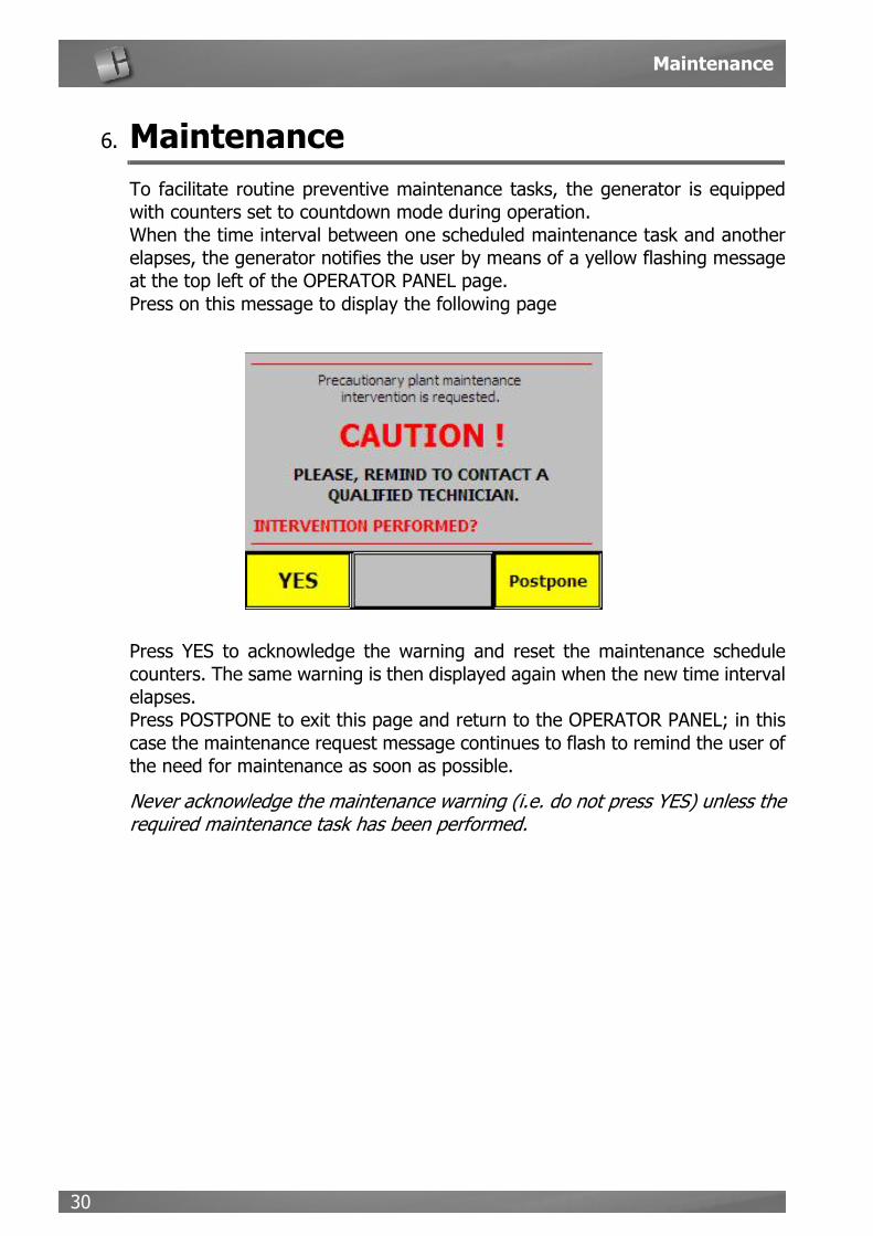
To facilitate routine preventive maintenance tasks, the generator is equippedwith counters set to countdown mode during operation.When the time interval between one scheduled maintenance task and anotherelapses, the generator notifies the user by means of a yellow flashing messageat the top left of the OPERATOR PANEL page.Press on this message to display the following page
Press YES to acknowledge the warning and reset the maintenance schedulecounters. The same warning is then displayed again when the new time intervalelapses. Press POSTPONE to exit this page and return to the OPERATOR PANEL; in thiscase the maintenance request message continues to flash to remind the user ofthe need for maintenance as soon as possible.
e Never acknowledge the maintenance warning (i.e. do not press YES) unless therequired maintenance task has been performed.

Nitrogen generator Laser Cut
31
6.1. Maintenance schedule
Please see the following scheme:LASER CUT 225

Maintenance
32
LASER CUT 450
WARNING: Only experienced personnel must do maintenance.CLAIND rejects any responsability for damages caused by uncorrected uses ofthe plant. Please contact CLAIND service department before doing any operationon the plant.

Nitrogen generator Laser Cut
33
7. Troubleshooting
7.1. Alarms
Any malfunctions or useful information for the operator are displayed on the tou-ch screen in two different ways:
WARNING: indicates an anomalous condition that may require intervention ofthe operator, but gas production is not shut down
ALARM: indicates a condition that prevents continuation of gas production. Inthis case the generator shuts down production and activates depressurisation.Therefore the generator must be shut down, after which eliminate the cause andrestart the generator
In both cases an acoustic warning signal is activated.To shut off the acoustic signal, press a text key on the screen to display theEVENT HISTORY page.From the EVENT HISTORY page, press ESC to access the OPERATOR PANELwhere a red indicator shows the cause of the alarm. The same page also displaysthe flashing yellow button ACK AMP to enable acquisition of the alarm.
The following section lists the possible warning and alarm messages.
7.1.1. ALARM: Air pressure too highCAUSE: activated when the compressed air pressure on inlet to the generator exceedsthe maximum admissible value.REMEDY:
• check the compressed air system for faults
Troubleshooting
34
• check the pressure sensor PT00
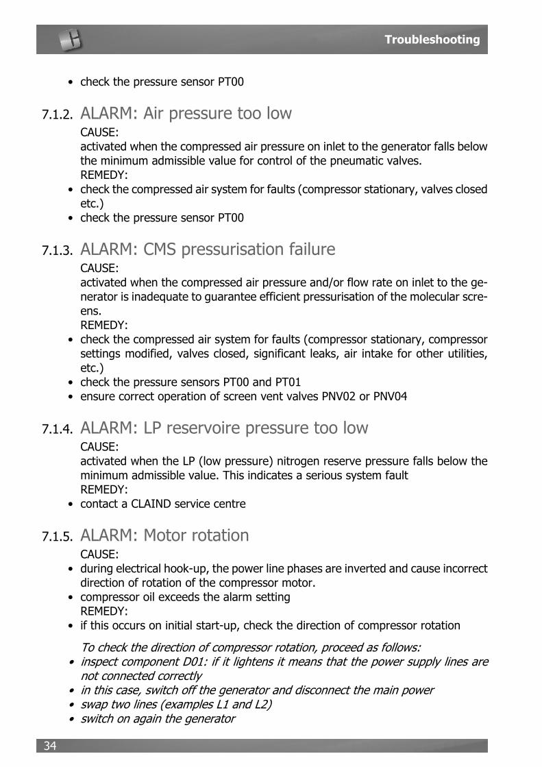
7.1.2. ALARM: Air pressure too lowCAUSE: activated when the compressed air pressure on inlet to the generator falls belowthe minimum admissible value for control of the pneumatic valves.REMEDY:
• check the compressed air system for faults (compressor stationary, valves closedetc.)
• check the pressure sensor PT00
7.1.3. ALARM: CMS pressurisation failure CAUSE: activated when the compressed air pressure and/or flow rate on inlet to the ge-nerator is inadequate to guarantee efficient pressurisation of the molecular scre-ens.REMEDY:
• check the compressed air system for faults (compressor stationary, compressorsettings modified, valves closed, significant leaks, air intake for other utilities,etc.)
• check the pressure sensors PT00 and PT01• ensure correct operation of screen vent valves PNV02 or PNV04
7.1.4. ALARM: LP reservoire pressure too low CAUSE: activated when the LP (low pressure) nitrogen reserve pressure falls below theminimum admissible value. This indicates a serious system faultREMEDY:
• contact a CLAIND service centre
7.1.5. ALARM: Motor rotationCAUSE:
• during electrical hook-up, the power line phases are inverted and cause incorrectdirection of rotation of the compressor motor.
• compressor oil exceeds the alarm settingREMEDY:
• if this occurs on initial start-up, check the direction of compressor rotation
e To check the direction of compressor rotation, proceed as follows:• inspect component D01: if it lightens it means that the power supply lines are
not connected correctly• in this case, switch off the generator and disconnect the main power• swap two lines (examples L1 and L2)• switch on again the generator
Nitrogen generator Laser Cut
35
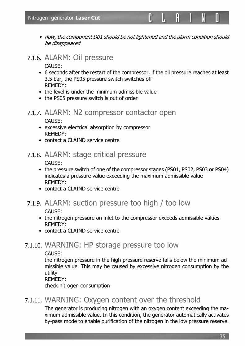
• now, the component D01 should be not lightened and the alarm condition shouldbe disappeared
7.1.6. ALARM: Oil pressure CAUSE:
• 6 seconds after the restart of the compressor, if the oil pressure reaches at least3.5 bar, the PS05 pressure switch switches offREMEDY:
• the level is under the minimum admissible value• the PS05 pressure switch is out of order
7.1.7. ALARM: N2 compressor contactor open CAUSE:
• excessive electrical absorption by compressorREMEDY:
• contact a CLAIND service centre
7.1.8. ALARM: stage critical pressure CAUSE:
• the pressure switch of one of the compressor stages (PS01, PS02, PS03 or PS04)indicates a pressure value exceeding the maximum admissible valueREMEDY:
• contact a CLAIND service centre
7.1.9. ALARM: suction pressure too high / too low CAUSE:
• the nitrogen pressure on inlet to the compressor exceeds admissible valuesREMEDY:
• contact a CLAIND service centre
7.1.10. WARNING: HP storage pressure too low CAUSE: the nitrogen pressure in the high pressure reserve falls below the minimum ad-missible value. This may be caused by excessive nitrogen consumption by theutilityREMEDY: check nitrogen consumption
7.1.11. WARNING: Oxygen content over the thresholdThe generator is producing nitrogen with an oxygen content exceeding the ma-ximum admissible value. In this condition, the generator automatically activatesby-pass mode to enable purification of the nitrogen in the low pressure reserve.

Troubleshooting
36
If this condition persists, the generator is unable to reach the rated flow rate andtherefore other alarms may trip.CAUSE:
• oxygen analyser supplied incorrect values• low flow rate and/or air pressure on inlet• air on inlet contaminated with oil vapours• malfunction of a vent valve (PNV03 or PNV04)
REMEDY: • check characteristics of air on inlet• check operating time of oxygen analyser• contact a CLAIND service centre
Nitrogen generator Laser Cut
37
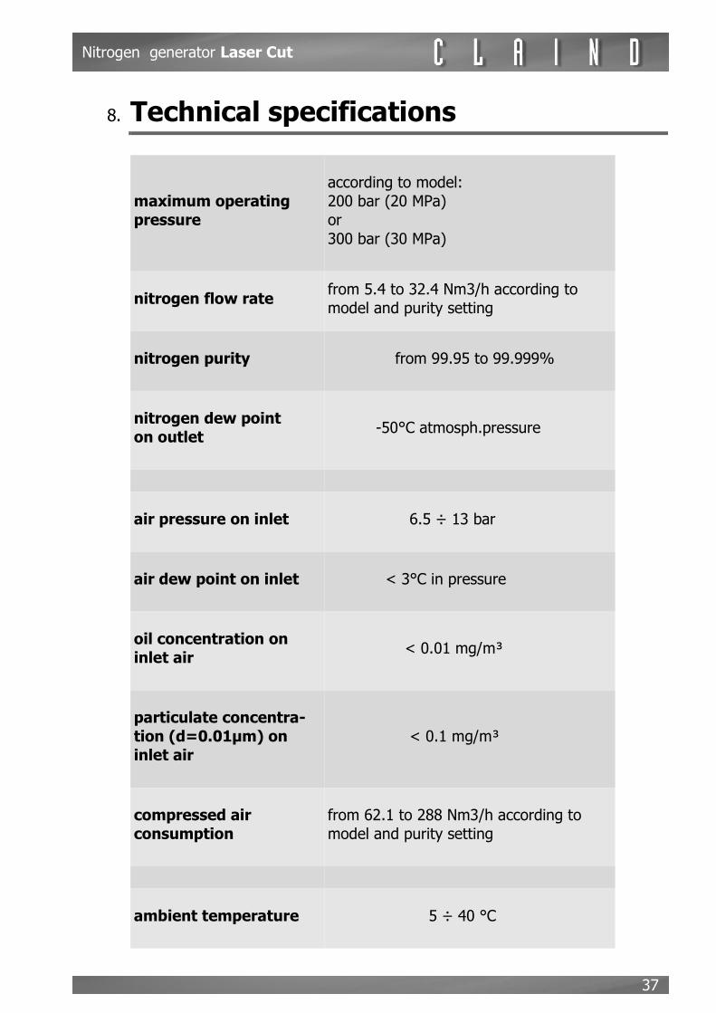
8. Technical specifications
maximum operating pressure
according to model:200 bar (20 MPa)or300 bar (30 MPa)
nitrogen flow ratefrom 5.4 to 32.4 Nm3/h according to model and purity setting
nitrogen purity from 99.95 to 99.999%
nitrogen dew point on outlet
-50°C atmosph.pressure
air pressure on inlet 6.5 ÷ 13 bar
air dew point on inlet < 3°C in pressure
oil concentration on inlet air
< 0.01 mg/m³
particulate concentra-tion (d=0.01µm) on inlet air
< 0.1 mg/m³
compressed air consumption
from 62.1 to 288 Nm3/h according to model and purity setting
ambient temperature 5 ÷ 40 °C

Technical specifications
38
Model 225 Model 450
cooling air flow rate 75 m3/min 160 m3/min
electrical power supply380/440 Vac 3ph+N; 50/60Hz
380/440 Vac 3ph+N; 50/60H
nitrogen compressor model
SV 225-250 N SVc 450-350 N
generator electrical power absorption
8 kW 16 kW
recommended minimum power cable section
2.5 mm2 6 mm2
noise level < 70 dB(A)

Nitrogen generator Laser Cut
39
DIMENSIONS AND WEIGHTS
Model 225 Model 450
width with 1 CMS module (a1)
290 cm 340 cm
width with 2 CMS modules (a2)
330 cm 380 cm
width with 3 CMS modules (a3)
370 cm 420 cm
width with 4 CMS modules (a4)
410 cm 460 cm
depth (b) 110 cm 110 cm
height (h) 207 cm 207 cm
total weight with 1 CMS module
1500 kg 1650 kg
total weight with 2 CMS modules
2150 kg 2300 kg
total weight with 3 CMS modules
2800 kg 2950 kg
total weight with 4 CMS modules
3450 kg 3600 kg

Declaration of conformity
40
9. Declaration of conformity

Nitrogen generator Laser Cut
41

Notes
42
10. Notes

Claind srlVia Regina, 2422016 Tremezzina Loc. Lenno (CO) - ItalyTel +39 0344 56603Fax +39 0344 56627e-mail [email protected]
N2 LaserCut eng Rev9.fm


![Untitled-1 [] · Nitrogen Generator. Compressed air can be supplied by customer, or MVS provides Air compressor as part of integrated package. Nitrogen Generator - The Nitrogen Generator](https://static.fdocuments.in/doc/165x107/5fc9ec742fa7e53c2c759a1d/untitled-1-nitrogen-generator-compressed-air-can-be-supplied-by-customer-or.jpg)


