Nitrogen gas system for the clean rooms at lab 3
17
1
Transcript of Nitrogen gas system for the clean rooms at lab 3

1

2
ODH analysis for the clean rooms at lab 3
Result:
The ODH classification is class 0. No special precautions are required.
The highest calculated fatality rate is Ø=ΣPi*Fi = 1.7 x 10⁻⁹ hr-1. This fatality rate was
calculated assuming that there is no ventilation.
Discussion
The interior cleanrooms generally referred to as cleanroom A and cleanroom B have
an inert gas distribution system that utilizes liquid cryogen boil-off. Flow rates and
volumes of the inert gas are described later in this note.
As a good engineering practice, an interlock box is part of the inert gas supply
system. Inert gas flow is permitted to each room only when that room’s air
circulation system is operating. The cleanrooms are shown to be class 0 neglecting
the interlock box.
Area Description
Figure 1. Plan view of cleanrooms A and B. Recirculation HVAC is shown.

3
Cleanroom A is 33’ wide x 34.5’ long x 12’ high. It has a floor area of 1100 square
feet and a volume of 13,860 cubic feet. Recirculated ventilation is provided by a
blower mixing the air at a rate of approximately 27 room air changes per hour.
Fresh air make-up is at least 325 cfm. The fresh air make-up was determined by
measuring the air velocity at a fresh air intake grille and multiplying by the area (9”
x 12”) to give 330 cfm. The measurement was made on Nov. 12, 2009 using a
Testoterm mini anemometer type 4400. Cleanroom A has a total ventilation rate
(recirculated plus fresh air) of 6200 cfm. Measurements were made on Feb. 28,
2008.
Figure 1. Cleanroom A. Also known as the north cleanroom.

4
Cleanroom B is 33’ wide x 62.7’ long x 12’ high. It has a floor area of 1900 square
feet and a volume of 22,800 cubic feet. Recirculated ventilation is provided by a
blower mixing the air at a rate of approximately 23 room air changes per hour.
Fresh air make-up make up was measured at an intake grill and is 800 cfm.
Cleanroom B has a total (recirculated plus fresh air) ventilation rate measured at
9600 cfm.
Figure 2. Cleanroom B. Also known as the south cleanroom.
Inert Gas Sources
Inert nitrogen or argon gas is supplied to both cleanrooms for purging materials and
detectors that are sensitive to radon gas. Boil-off from these cryogenic liquids is low
in radon concentration. The inert gas source is a 160 liter or 180 liter liquid nitrogen
or argon dewar, located outdoors, near the gas bottle storage area at the south end of
the building. Only one type of gas, nitrogen OR argon is used. Only one liquid
dewar is connected at any time. As a back-up system, each cleanroom also has a
single compressed gas cylinder that supplies gas if the pressure drops below 15 psig.
The liquid nitrogen dewar is FNAL stock number 1980-200500. The description is:
LIQUID NITROGEN, MINUIMUM PURITY 99.995 PCT., OUTLET FOR
LIQUID WITHDRAWAL IS 1/2 IN. FLARE MALE FITT. 180 LITER 22 PSI
DEWAR, NON -FLAMMABLE
A 180 liter liquid nitrogen dewar contains 180 liters * (687 gas STP/liquid @BP) *
(0.1337 ft3/3.785) = 4368 standard cubic feet nitrogen.

5
Figure 3: Inert gas system component flow diagram
A compressed gas cylinder of nitrogen contains 228 standard cubic feet of nitrogen.
The nitrogen is FNAL stock # 1980-120000. The description is: NITROGEN GAS,
COMPRESSED, PRE-PURIFIED, MINIMUM PURITY 99.995%, CGA 580
FITTING, 2265 PSIG AT 70 DEG., 228 SCF CYLINDER SIZE, NON-
FLAMMABLE.
The total gas inventory = 4368 scf + 228 scf = 4596 scf nitrogen.
Or, if we are using the system for argon;
The liquid argon dewar is FNAL stock number 1980-190500, LIQUID ARGON,
MINIMIN PURITY 99.997PCT., OUTLET FOR LIQUID WITHDRAWAL IS 1/2
IN., FLARE MALE FITT. 180 LITER, 230 PSI DEWAR, NON-FLAMMABLE.
A 180 liter liquid argon dewar contains 180 liters * (687 gas STP/liquid @BP) *
(0.1337 ft3/3.785) = 5462 standard cubic feet argon.
A compressed gas cylinder of argon contains 248 standard cubic feet of nitrogen.The
argon is FNAL stock # 1980-108000, ARGON GAS, COMPRESSED, IND.

6
GRADE, MINIMUM PURITY 99.995 PCT. CGA 580 FITTING, 2400 PSIG AT 70
DEG., 248 SCF CYLINDER SIZE, NON-FLAMMABLE
The total gas inventory = 5462 scf + 248 scf = 5710 scf argon.
ODH Classification methodology The safety analysis methodology that will be followed is Fermilab’s safety and
health manual chapter on Oxygen Deficiency Hazards, FESHM 5064 revision May
2009. Sections of this chapter are excerpted below.i
The oxygen deficiency hazard fatality rate is defined as:
where Ø = the ODH fatality rate (per hour),
Pi = the expected rate of the ith event (per hour), and
Fi = the probability of a fatality due to event i.
The summation shall be taken over all events, which may cause oxygen deficiency and result in fatality. The value of Fi is the probability that a person will die if the ith event occurs. The value depends on the oxygen concentration. If the lowest oxygen concentration is greater than 18%, then the value of Fi is zero, that is, all exposures above 18% are defined to be "safe" and to not contribute to fatality. It is assumed that all exposures to 18% oxygen or lower do contribute to fatality and the value of Fi is designed to reflect this dependence. If the lowest attainable oxygen concentration is 18%, then the value of Fi is 10-7. This value would cause f to be 10-7 per hour if the expected rate of occurrence of the event were 1 per hour. At decreasing concentrations, the value of Fi should increase until, at some point, the probability of fatality becomes unity. That point was selected to be 8.8% oxygen, the concentration at which one minute of consciousness is expected.
The worst ODH condition will occur when the inert gas has been flowing for the
longest. Inert gas from the dewar would only flow until the dewar empties. The
oxygen concentration at that time can be calculated. Then inert gas from the back up
cylinder flows for a time and after that period the oxygen concentration can be
calculated. A fatality factor can be assessed based on that final oxygen

7
concentration. The probabilities of failure are multiplied by that fatality factor to
yield the ODH fatality rate, Ø.
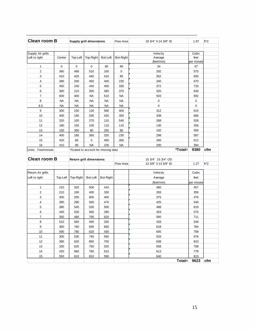
Maximum possible gas flow rates
A 0.375 inch OD copper tube carries the gas from the dewar outside along the inside
of the east wall of the main building to the interlock control box located midway
along the exterior of the east wall of the clean rooms. The tubing run is about 200
feet. The gas pressure at the dewar is 22 psig. The maximum flow rate through 200
feet of 3/8” OD copper tubing is calculated to be 300 scfh = 5 scfm when the system
is used for nitrogen. The maximum flow rate when we are using argon is 250 scfh =
4.2 scfm. The calculation of these flow rates is shown on page 4 of the attached
hand calculations.
The back up gas cylinders are regulated to 15 psig at the cylinder valve and are
connected with 32 feet of 0.375” OD tubing to a check valve and tee located at the
interlock box location. The previous maximum flow calculation can be scaled by
recognizing that flow rate is proportional to the square root of the absolute pressure
and inversely proportional to square root of the tubing length. The average absolute
pressure along the tubing length is used. When nitrogen is being supplied by the
back-up cylinder, the flow rate is:
When argon is being supplied by the back-up cylinder, the flow rate is:
Elapsed time of release
When using nitrogen, the dewar containing 4368 scf, divided by the maximum flow
rate of 5 scfm yields the result that the dewar would run out in 874 minutes. The
nitrogen back up cylinder would run out in 228 scf divided by 11.5 scfm = 20
minutes.
When using argon, the dewar containing 5462 scf, divided by the maximum flow
rate of 4.2 scfm yields the result that the dewar would run out in 1300 minutes. The
argon back up cylinder would run out in 248 scf divided by 9.6 scfm = 26 minutes.

8
Oxygen Concentrations after elapsed times and ODH classification
Normal Ventilation
It is first assumed that we have normal ventilation conditions with fresh air make up
of Q = 330 cfm in cleanroom A and Q = 800 cfm in cleanroom B. The volume,
V=13,860 cubic feet for cleanroom A and V=22,800 cubic feet for cleanroom B.
The oxygen concentration is given by FESHM 5064TA.
Case A During release - Ventilation fan(s) blowing outside air into the confined volume. Differential equation for the oxygen mass balance
(1)
Solution with the boundary condition of C=0.21 at t=0
(2)
Definitions
C = oxygen concentration
Cr = oxygen concentration during the release
Ce = oxygen concentration after the release has ended
Q = ventilation rate of fan(s), (cfm or m3/s)
R = spill rate into confined volume, (scfm or m3/s)
t = time, (minutes or seconds) beginning of release is at t=0
te = time when release has ended, (minutes or seconds)
V = confined volume, (ft3 or m3)
Cleanroom A, Nitrogen as a source gas. We have R = 5 scfm flowing for t=874
minutes and R=11.5 scfm flowing for t=20 minutes.
After the dewar has released its inventory, the oxygen concentration is:
]
9
The e- term is 10E-9 and is therefore negligible. It is conservative to drop this term.
It will be neglected for all remaining calculations.
C = 0.21 * [330/(330+5)] = 0.207 = 20.7%
After the backup cylinder is empty, the oxygen concentration is:
C = 0.207 * [330/(330+11.5)] = .1999 = 20.0 %.
Cleanroom A, Argon as a source gas. We have R = 4.2 scfm flowing for t=1300
minutes and R=9.6 scfm flowing for t=26 minutes.
C = 0.21 * [330/(330+4.2)] = 0.207 = 20.7%
After the backup cylinder is empty, the oxygen concentration is:
C = 0.207 * [330/(330+9.6] = .201 = 20.1 %.
Cleanroom B, Nitrogen as a source gas
C = 0.21 *[800/(800+5)] = .209 = 20.9% after the dewar empties and,
C = 0.209 *[800/(800+11.5)] = .206 = 20.6% after the back up cylinder empties.
Cleanroom B, Argon as a source gas
C = 0.21 *[800/(800+4.2)] = .209 = 20.9% after the dewar empties and,
C = 0.209 *[800/(800+9.6)] = .206 = 20.6% after the back up cylinder empties.

10
Table 1. Oxygen concentrations in cleanroom A & B for nitrogen or argon being
used. Normal ventilation conditions.
Nitrogen service Argon service
Cleanroom A 20.0 % 20.1 %
Cleanroom B 20.6 % 20.6 %
All oxygen concentrations above 18% are considered safe. The probability of a
fatality, Fi for oxygen concentrations greater than 18% is zero. Therefore regardless
of the event that caused the release, the fatality rate is also zero.
Ø, , Ø = 0.0 and the ODH classification is 0.
Oxygen Concentrations after elapsed times and ODH classification
(continued)
Abnormal ventilation
As a second case to consider, what if the ventilation is not normal? The most likely
scenario is a power outage. In that case, the normally closed solenoid valve in the
interlock box would close stopping flow from the dewar. Only the back up cylinder
volume could be released into the room. A release of 250 scfh of inert gas into the
volume of the smaller cleanroom, A = 13,800 cubic feet, would result in an oxygen
concentration of C = 0.21* [(13,800-250)/13,800] = 0.206 = 20.6%. Cleanroom B
ends in a concentration of 20.8%. Since the oxygen concentration is above 18%, the
ODH classification is 0.
What if the solenoid valve in the interlock box didn’t close? The probability of a
power outage is 1.0E-4 hr-1 and the failure rate of the solenoid to fail to close is
1.0E-3 per demand from FESHM 5064 table 2. So the probability of both a power
outage and the solenoid failing to close is the multiple of those two numbers = Pi =
1.0E-7. In this case the fatality factor, Ø = summation of Pi*Fi would be less than or
equal to 1.0E-7 hr-1
and the ODH classification is 0.
What if the belts on the recirculation fan break or the power to only the fans is
disrupted? Even though there would not be forced ventilation, some mixed gas
would exit the room through leaks. The room would initially be pressurized (it’s
normal state) but eventually would come to equilibrium with an exhaust rate at least
equal to the incoming leak rate.
In this case, the oxygen concentration can be calculated as per case C in FESHM
5064. .
Cleanroom A, Nitrogen as a source gas. We have R = 5 scfm flowing for t=874
minutes and R=11.5 scfm flowing for t=20 minutes. V= 13,800 cubic feet.

11
After the dewar has released its inventory, the oxygen concentration is:
C(t) = 0.21 * e-(5*874/13,860)
= 0.153 = 15.3%.
After the backup cylinder is empty, the oxygen concentration is:
C(t) = 0.153 * e-(11.5*20/13,860)
= 0.150 = 15.0%.
Cleanroom A, Argon as a source gas. We have R = 4.2 scfm flowing for t=1300
minutes and R=9.6 scfm flowing for t=26 minutes.
After the dewar has released its inventory, the oxygen concentration is:
C(t) = 0.21 * e-(4.2*1300/13,860)
= 0.141 = 14.1%.
After the backup cylinder is empty, the oxygen concentration is:
C(t) = 0.141 * e-(9.6*26/13,860)
= 0.139 = 13.9%.
Cleanroom B, Nitrogen as a source gas
C(t) = 0.21 * e-(5*874/22,800)
= 0.173 = 17.3%.
After the backup cylinder is empty, the oxygen concentration is:
C(t) = 0.173 * e-(11.5*20/22,800)
= 0.171 = 17.1%.
Cleanroom B, Argon as a source gas
C(t) = 0.21 * e-(4.2*1300/22,800)
= 0.165 = 16.5%.
After the backup cylinder is empty, the oxygen concentration is:
C(t) = 0.165 * e-(9.6*26/22,800)
= 0.163 = 16.3%.
Table 2. Oxygen concentrations in cleanroom A & B for nitrogen or argon being
used. Loss of ventilation condition where exhaust flow equals leak rate in. Partial
pressure O2
Nitrogen service Argon service
Cleanroom A 15.0 %, 112.5 mmHg 13.9 %, 104.3 mmHg
Cleanroom B 17.1 %, 128.3 mmHg 16.3 %, 122.3 mmHg
The probability of a fatality for oxygen concentrations are given in FESHM 5064 as
presented in the graph below. In the graph below,135 mmHg oxygen partial

12
pressure corresponds to 18%.
Table 3. Probability of Fatality, Fi, in cleanroom A & B for nitrogen or argon being
used. This is the case of loss of ventilation where exhaust flow equals leak rate in.
Nitrogen service, Fi Argon service, Fi
Cleanroom A 1.8E-5 hr-1
1.2E-4 hr-1
Cleanroom B 4.7E-7 hr-1
1.9E-6 hr-1
Events and Probabilities
Recall that the only scenario that resulted in a non-zero probability of a fatality is
when the ventilation fans are off due to a belt breakage, failure to start or run, etc.
The probability of this can be estimated as a motor or pump that fails to start. Pi =
10E-5 hr-1
from FESHM 5064, Table 2. This probability of failure should be
multiplied by the probability of any event that causes a release to arrive at the
probability of both occurring at the same time. However, to be conservative and to
not have to worry about maintenance periods on the fan, etc. I choose to change the
probability of the fan being off to 1.0. This means that the fan could be off on
purpose and this ODH analysis would still apply.
There are three events to consider that would lead to an inert gas release. Probability
rates are from FESHM 5064 Table 2.
1.) The most likely event is operator error. An operator error of forgetting to re-
close a valve is 1 in 100 (.01) per demand. The gas supply is normally used as a
steady state purge of about 1 scfh (negligible in terms of ODH). I assume an
operator would have an occasion to operate a valve once per month. That leads to a
probability of release Pi = 1.4E-5 hr1.
2.) Another event is the rupture or leakage of a valve or fitting. There are five or
less valves per room and say 15 or less fittings for a total, N = 20 items. The
probability of a rupture of a valve or fitting is 1E-8 hr1. Multiplying that by 20 gives
Pi = 2 E-7hr1.

13
3.) The last event is the breakage and leakage of the tubing line. There are only two
gas drops in the room. Each drop has a manifold. Let N = 4. The probability of a
breakage or leakage of the tubing line is 10E-9hr1. Multiplying by N, Pi = 4E-9 hr
1.
The flow rate for all these events is taken at worst case, maximum resulting in the
probability of fatality as listed in Table 3. Since Fi is the same for each event it can
be factored out of the summation.
Ø = =
With Fi taken from table 3, the result of the multiplication is the fatality rate, Ø. The
values are shown in Table 4 below.
Table 4. Fatality rate, Ø in cleanroom A & B for nitrogen or argon being used.
This is the case of loss of ventilation where exhaust flow equals leak rate in.
Nitrogen service, Ø Argon service, Ø
Cleanroom A 2.6E-10 hr-1
1.7E-9 hr-1
Cleanroom B 6.7E-12 hr-1
2.7E-11 hr-1
Result
The highest summed ODH fatality rate per hour is 1.7E-9. This is well below the
ODH class 1 threshold of 1E-7 per hour and therefore the cleanrooms are ODH class
0. No special precautions are needed with regard to ODH.

14
Appendix 1.
Cleanroom A & B supply and return ventilation measurements
Clean room A Supply grill dimensions: Flow area 23 3/4" high X 14 5/16" wide 2.35 ft 2̂
Cover 31 3/4" high X 53 1/4" wide
Supply Air grills Velocity Velocity Velocity Velocity Velocity Velocity Cubic
Left to right Center Top-Left Top-Right Bot-Left Bot-Right Average feet
(feet/min) per minute
1 0 0 240 0 340 116 273
2 340 290 430 380 300 348 818
3 450 120 400 0 380 270 635
4 230 340 0 470 260 260 611
5 300 90 250 200 350 238 559
6 430 90 240 300 180 248 583
7 430 240 270 360 160 292 686
8 420 320 210 430 150 306 719
9 340 220 250 440 210 292 686
10 350 120 190 250 340 250 588
Units: Feet/minute Total= 6157 cfm
Clean room A Return grill dimensions: Flow area 15 3/4" X 15 3/4" OD 1.72 ft 2̂
Cover 13 3/8" X13 5/8" ID
Return Air grills Velocity Cubic
Left to right Top-Left Top-Right Bot-Left Bot-Right Average feet
(feet/min) per minute
1 400 710 530 230 467.5 804
2 330 550 570 320 442.5 761
3 230 520 380 560 422.5 727
4 210 380 460 460 377.5 649
5 200 420 780 400 450 774
6 350 490 480 600 480 826
7 410 640 690 620 590 1015
8 400 600 650 800 612.5 1054
Total= 6609 cfm
15
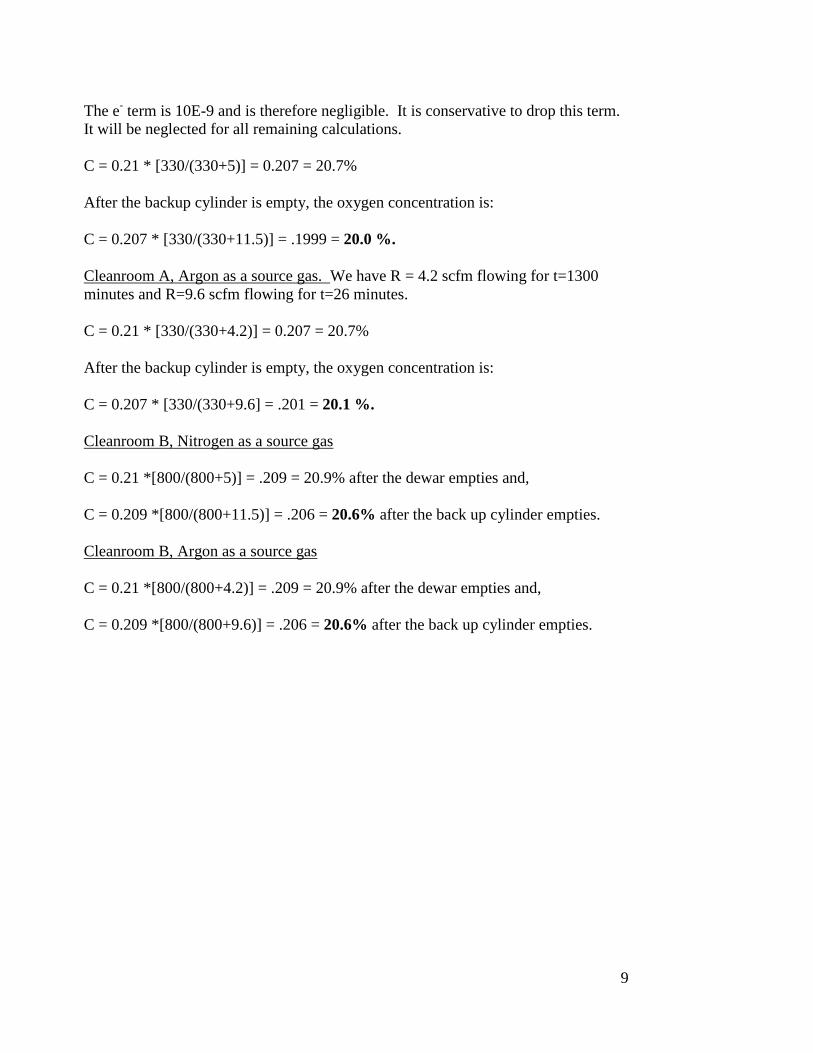
Clean room B Supply grill dimensions: Flow Area 19 3/4" X 14 3/8" ID 1.97 ft 2̂
Supply Air grills Velocity Cubic
Left to right Center Top-Left Top-Right Bot-Left Bot-Right Average feet
(feet/min) per minute
1 0 0 0 80 90 34 67
2 360 490 510 100 0 292 575
3 410 420 440 410 80 352 693
4 380 200 450 440 230 340 670
5 450 240 440 400 330 372 733
6 360 210 300 360 370 320 630
7 600 400 NA 510 NA 503 992
8 NA NA NA NA NA 0 0
8.5 NA NA NA NA NA 0 0
9 300 150 130 580 400 312 615
10 400 190 330 420 350 338 666
11 320 100 270 110 540 268 528
12 180 150 100 110 110 130 256
13 150 350 80 250 80 182 359
14 400 180 360 320 230 298 587
15 420 80 0 450 350 260 512
16 410 90 NA 100 NA 200 394
Units: Feet/minute *Scaled to account for missing data *Total= 9380 cfm
Clean room B Return grill dimensions: 15 3/4" 15 3/4" OD
Flow Area 13 3/8" X 13 5/8" ID 1.27 ft 2̂
Return Air grills Velocity Cubic
Left to right Top-Left Top-Right Bot-Left Bot-Right Average feet
(feet/min) per minute
1 210 320 500 410 360 457
2 210 190 400 330 283 359
3 300 200 600 400 375 476
4 390 280 560 470 425 540
5 380 540 530 500 488 619
6 440 530 560 280 453 575
7 350 480 790 620 560 711
8 510 560 460 200 433 549
9 360 760 690 660 618 784
10 590 780 620 430 605 768
11 300 530 740 560 533 676
12 380 620 850 700 638 810
13 330 620 760 520 558 708
14 420 660 760 610 613 778
15 550 610 810 590 640 813
Total= 9623 cfm

16
17