Nissan Tuning Guide - UpRev - Performance Tuning Softwareuprev.com/UpdateFiles/software/UpRev Nissan...
14
UpRev LLC UpRev Nissan Tuning Guide Page 1 of 14 Nissan Tuning Guide
Transcript of Nissan Tuning Guide - UpRev - Performance Tuning Softwareuprev.com/UpdateFiles/software/UpRev Nissan...

UpRev LLC UpRev Nissan Tuning Guide
Page 1 of 14
Nissan Tuning Guide

UpRev LLC UpRev Nissan Tuning Guide
Page 2 of 14
Contents 1. Knowing Which ROM to use ............................................................................................................................................. 3
2. Fuel Parameters ............................................................................................................................................................... 3
Fuel Targets: .................................................................................................................................................................. 3
Fuel Compensation: ...................................................................................................................................................... 3
K - Fuel Multiplier: ......................................................................................................................................................... 4
Mass Air Flow Sensor: ................................................................................................................................................... 4
Cranking Enrichment: .................................................................................................................................................... 5
Cylinder Trim: ................................................................................................................................................................ 6
Injector Minimum: ........................................................................................................................................................ 6
Fuel Target Lookup Delay: ............................................................................................................................................. 6
Adjust Injector Latency: ................................................................................................................................................ 6
Calculated Load ............................................................................................................................................................. 6
3. Ignition Advance Parameters ........................................................................................................................................... 7
Ignition Timing: ............................................................................................................................................................. 7
Ignition Timing Knock Windows: ................................................................................................................................... 8
4. GTR Boost Control ............................................................................................................................................................ 8
Flow Target Modifier ..................................................................................................................................................... 8
Boost Sol Table .............................................................................................................................................................. 8
Flow Delta Sensitivity .................................................................................................................................................... 8
5. Rev & Speed Limits ......................................................................................................................................................... 10
6. Camshaft advance .......................................................................................................................................................... 10
7. Electronic Throttle .......................................................................................................................................................... 10
8. Torque Management ...................................................................................................................................................... 10
Estimated Torque Delivered: ...................................................................................................................................... 10
9. Misfire............................................................................................................................................................................. 10
Crank Drag A, B, and C: ............................................................................................................................................... 10
10. Idle targets ...................................................................................................................................................................... 11
11. Utilities ........................................................................................................................................................................... 11
12. Settings ........................................................................................................................................................................... 11
13. Loggable parameter descriptions ................................................................................................................................... 12
UpRev ROM specific parameters ................................................................................................................................ 12
Nissan Standard parameters ....................................................................................................................................... 12
14. Basic Forced Induction Tuning Session .......................................................................................................................... 12

UpRev LLC UpRev Nissan Tuning Guide
Page 3 of 14
This guide was written with the assumption that the reader has already read the Osiris User Guide. At least the last few
sections regarding using and navigating the Osiris ROM Editor. It is also assumed that the reader is an experienced tuner
with a solid understanding of internal combustion engine tuning techniques.
Keep in mind that some ROM versions have parameters that other ROMs do not.
1. Knowing Which ROM to use To find out what ROM should be used on a given vehicle, check the ECU part number with any of the UpRev software.
Then reference that number against the “ROM Support Matrix” which can be found in the UpRev directory or under
Start >> All Programs >> UpRev >> ROM support matrix. The “MASTER” ROMs are the ROMs that overwrite any older
versions. Use the master ROM for tuning.
2. Fuel Parameters
Fuel Targets:
X – Axis = BFS (theoretical injector PW), Y – Axis = RPM
This table is pretty straight forward. The values in the table tell the ECU what AFR target to try to run.
** Fuel targets tuning tips:
This table should be set to the AFR targets you WANT the ECU to run. Once the table is setup the way you want the car
to run there should be no reason to adjust it again. You should be using the fuel compensation table or MAF curve to
correct the injector pulse widths so that the ECU hits the targets you’re telling it to run. If you try to adjust this table to
get the ECU to hit a desired AFR, but that AFR is not what you put in the target table then the ECU will trim to the targets
you’re telling it to hit instead of what you’re tuning it to hit and it will likely throw bank rich/lean DTCs. Once you have
the fuel compensation and MAF curve tuned so that the ECU is hitting the targets you’re telling it to hit, then adjusting
the tune to run new targets is as simple as changing this table. It should hit new targets with little to no tuning once the
other fuel parameters are dialed in.
Fuel Compensation:
X – Axis = UNKNOWN theoretical value; Y – Axis = RPM
There are 2 types of fuel compensation tables to be aware of depending on what ROM you are working with.
Fuel Compensation Main is the primary table that every ROM uses.
Fuel Compensation Cold is only used on some of the newer vehicles. This table is only used when the vehicle is still in
warm up stage. Once the coolant temperature gets up to 80 C, then the ECU will switch to the Main table.
For both tables, the values represent a change to base fuel schedule (BFS) as a %. 100 is no adjustment at all. Above
100 is adding injector PW, and below 100 is taking injector PW out.
** Fuel Compensation tuning tips:
This is one of the tables that you will use to correct the AFR so that the ECU hits the AFR targets that you are telling it to
hit in the Fuel Target table. Tuning it is pretty straight forward. Increase the values to richen the AFR and decrease
them to lean out the AFR.

UpRev LLC UpRev Nissan Tuning Guide
Page 4 of 14
K - Fuel Multiplier:
This is the multiplier that the ECU uses to determine the base fuel schedule (BFS). The BASIC formula is current MAF
value times K value = BFS. Base fuel schedule is the theoretical pulse width that the ECU would have to run in order to
maintain a 14.7 AFR. This is NOT the actual injector pulse width. The ECU will increase the injector pulse width based on
the AFR target, fuel trims, other run time variable parameters, and environmental conditions.
There are a couple situations where you need to adjust the K value. You will need to decrease it when running larger
injectors, and increase it when running a modified MAF sensor such as a PMAS sensor, UpRev calibrated sensor or larger
MAF tube.
** K Fuel Multiplier tuning tips:
Regardless of if you’re adjusting the K value for injectors or MAF sensor, start by setting up an “AFR test” table in the
AFR targets. This table should have the same value everywhere except for the cranking and idle area. The RPM axis
should also be adjusted so that with any increase in load and RPM the ECU will immediately start running the “flat” AFR
target that you set. Here is an example of an AFR test table used to tune the K fuel multiplier:
With the AFR test map loaded start doing pulls and watching the AFR. Keep adjusting the K value until the AFR starts to
get as close to the target as you can get it throughout the entire RPM range. It won’t be perfect, but get is as close as
possible. Increasing the K will make it richer, decreasing the K will lean it out.
Once the K value is dialed in you can do the rest of the AFR tuning either with the fuel compensation table, or with the
MAF table. The MAF table gives more precise adjustability, but it is not real time tunable so it takes longer to tune.
Mass Air Flow Sensor:
Single axis = sensor voltage. Axis is static (not adjustable).
Although the values in this table are raw (no real world conversion) they are directly related to grams per second of
flow.
** MAF table tuning tips:
Tuning the table is very straight forward. Increasing the values will increase the injector PW and decreasing them will
decrease the injector PW at the given voltage.
** PMAS tuning tips: The PMAS sensors are VERY inconsistent from one sensor to the next, especially in the low voltage
areas (below ~2V). To start, you will need to load the PMAS pre tuned curve with the utility named “Select MAF Type”
found under the fuel section of the ROM tree. This curve will get it into the ballpark, but it will still need a lot of work,
especially in the low voltage areas (idle, cranking). You MUST dial the K value in under some load so that the MAF is
running over 2V. Once you have the K value set for load so that the ECU is hitting the targets that you’re telling it to hit,
you will have to make adjustments to the MAF curve so that the car will idle correctly. After that you will still have to
make adjustments to the rest of the MAF curve to get your AFRs perfect.
UpRev LLC UpRev Nissan Tuning Guide
Page 5 of 14
** Helpful trick: If you’ve had to raise the MAF values so high that the table is maxed out you can give yourself some
more head room by raising the K value via multiplying it and then multiply the entire MAF table by the inverse of that
value. For example, multiply the K value by 1.2 (120%) and then multiply the ENTIRE MAF table by .8 (80%). The end
result is that the vehicle will run exactly the same, but you will have more room to raise the MAF table.
Cranking Enrichment:
Axis = coolant temp. Axis is static (not adjustable)
The cranking enrichment is very similar to the fuel compensation table. It will modify the BFS by a % based on the table
lookup. Just like the fuel compensation table above 100 is adding fuel and below 100 is taking fuel out.
Cranking Minimum Pulse Width Mode 1 – 4:
Axis = coolant temp or RPM depending on table and ROM. Axis are static (not adjustable)
These tables vary from vehicle to vehicle, but they all have the same effect of setting a minimum pulse width during
cranking. The actual injector pulse width during cranking does NOT match with what the ECU will log but can be verified
with an oscilloscope.
** Cranking Enrichment tuning tips: One helpful tip for tuning cranking enrichment is to use the fuel compensation
table. The fuel compensation table DOES still affect the injector PW during cranking. Watch the tracers for the fuel
compensation table to see where it runs during cranking. It should be somewhere in the upper right hand corner. Set
those cells to 100 and try to crank the engine. Try making adjustments in one direction or the other until you find the
sweet spot. Once you have it cranking well, you can take the change from the fuel compensation table and use the
change to multiply the cranking enrichment table and set the fuel compensation back to 100. Example: if the fuel comp
had to be set to 82 for good cranking, multiply the cranking enrichment table by .82. If you can’t get it to lean out
enough with the enrichment table also lower the “Cranking Minimum Pulse Width” tables.
If you’ve lowered the cranking enrichment by a significant amount and nothing is changing, verify that the injector pulse
width IS actually changing. There is a good chance that it may be bottoming out on the minimum injector pulse width
value, or possibly even the injector latency. You may need to lower the injector minimum pulse width value, or reduce
the injector latency 14V offset to bring the latency down.
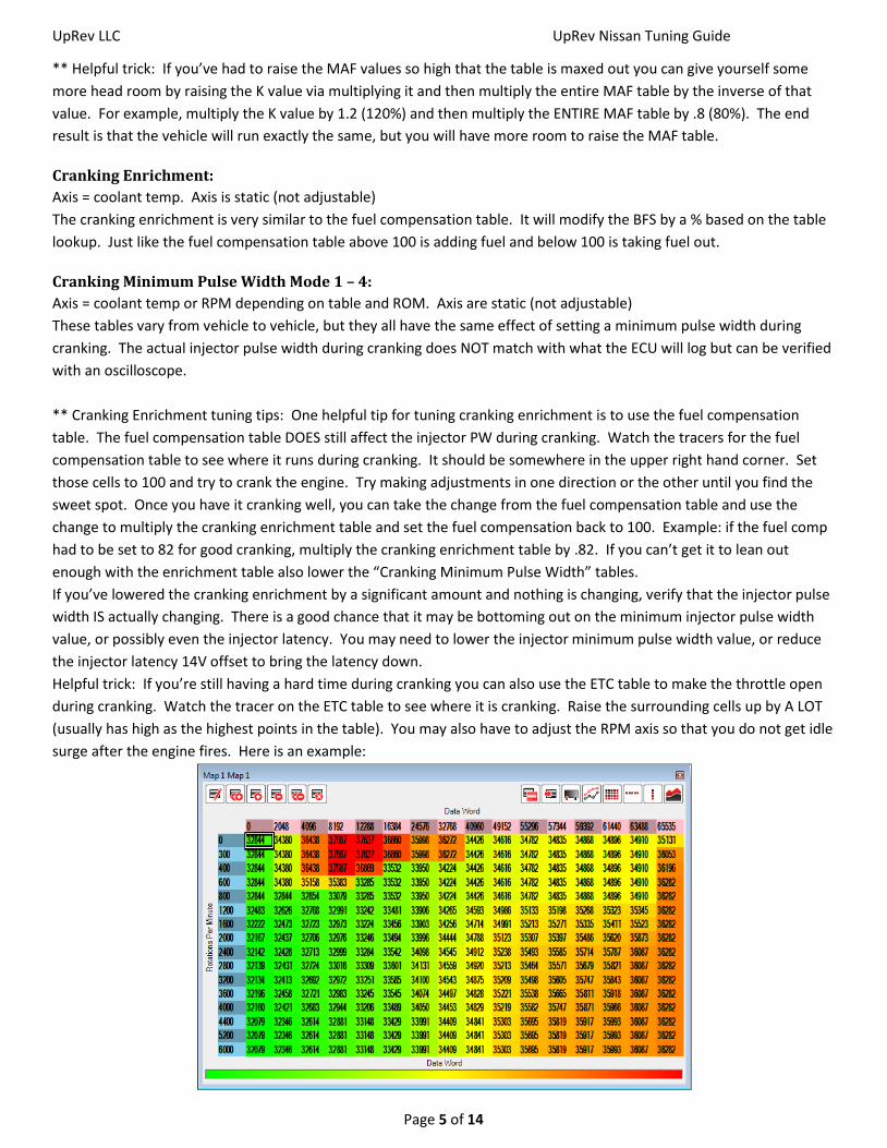
Helpful trick: If you’re still having a hard time during cranking you can also use the ETC table to make the throttle open
during cranking. Watch the tracer on the ETC table to see where it is cranking. Raise the surrounding cells up by A LOT
(usually has high as the highest points in the table). You may also have to adjust the RPM axis so that you do not get idle
surge after the engine fires. Here is an example:

UpRev LLC UpRev Nissan Tuning Guide
Page 6 of 14
Cylinder Trim:
This table is also pretty straight forward. It will adjust the injector PW for a single cylinder across the board. Much the
same as the other compensation tables, above 100 is adding fuel and below 100 takes fuel out.
Injector Minimum:
Injector Minimum Pulse Width is the minimum injector pulse width that the ECU will ever run during normal operating
conditions.
** Injector Minimum tuning tips:
The common reasons to change this parameter are:
Vehicle is backfiring on deceleration fuel cut.
Idling or cranking too rich, but the K value, MAF table and fuel comp do not bring the injector PW down.
Fuel Target Lookup Delay:
This parameter is only available on a small number of ROMs, most of which are for V8 engines. It effects are really only
noticeable on the V8 engine tunes. This parameter is a delay constant that is used to “smooth” the AFR lookup when
the throttle is snapped open.
** Lookup delay tuning tips: Most often you will want to set this value to “0” when tuning a V8 vehicle. This becomes
particularly critical when tuning for forced induction. If the value is left stock, then when the throttle is snapped open
the AFR will slowly taper down to the rich setting and the engine will probably do some pinging while it’s still running the
leaner targets leading to engine damage in the long run.
Adjust Injector Latency:
Injector latency in Nissan ECUs is modeled by a simple line (y = mX + B) where the 14V offset is the constant B and m is
the slope of the line. This utility/wizard is used to calculate the injector latency for a given 14V offset and slope and tell
you what the latency will be for any given voltage.
** Injector latency tuning tips: For injectors < 750cc you can usually just run the stock latency values. The best
technique is to get the injector latency values from the injector manufacturer and try to match up the 14V and 8V data
points. 14V is for normal operating conditions and 8V is how low the voltage may drop during cranking.
If you don’t have any latency values from the manufacturer you can adjust the slope by monitoring the A/F corrections,
then load up the battery as much as possible by switching on the headlights, seat heaters, heater blower, etc… If the
corrections go up, increase the slope, if the corrections drop, lower the slope. It’s not a perfect method, but it will get it
close.
Calculated Load
Axis = Engine RPM. Axis is static (not adjustable).
The ECU calculates the calculated load by dividing the current base fuel schedule into the value that is in this table for
the given RPM.
** Calculated load tuning tips:
The calculated load will affect the way the AT reacts. It is particularly important that the calculated load read 100% at
WOT on a forced induction AT vehicle so that the AT computer will run the correct line pressures. If you are not logging
100% at WOT, lower the values in this table at the given RPM.

UpRev LLC UpRev Nissan Tuning Guide
Page 7 of 14
3. Ignition Advance Parameters
Ignition Timing:
X-Axis = Base Fuel Schedule; Y-Axis = Engine RPM
Nissan handles ignition timing a bit differently than what most tuners are used to working with. For max horse power
with an internal combustion engine running gasoline you need the peak cylinder pressure to occur at 12-15 degrees
after top dead center (ATDC). What most experienced tuners are used to seeing is a value that represents when the
spark plug is fired in degrees before TDC.
What is seen in the Nissan table is a representation of the TIME that it takes for the cylinder pressure to reach peak
pressure after the plug is fired. The ECU uses this “burn time” to calculate when the plug should be fired in order to get
the peak cylinder pressure to occur at the desired 12-15 degrees. Because this table represents time, when it is fully
tuned it tends to come out pretty flat, but the ECU will still run an increasing curve with RPM.
** Ignition Timing tuning tips:
There are a few different timing tables that Nissan ECUs employ.
Timing Main – This is the primary ignition table that is used under normal operation.
Timing High Det – This is the ignition table that the ECU will use if it hears too much noise on the knock sensor.
Timing Cold – This table is only found in the newer Nissan ECUs and it is only used until the coolant temp gets up to 80
degrees C. At that point the ECU will switch over to the “Main” table.
Although there is no way to convert the table to DBTDC, adjustments are made in the same way as any typical timing
table. Higher values yield more ignition advance. The only proper way to tune ignition advance is with the assistance of
a dynamometer so that you can verify that the added advance is adding power and not just stress on the engine
internals.
When tuning any vehicle it is good practice to make sure that the ignition table is not being accessed outside of the
boundaries of the table. The easiest way to do this is to use the “map tracing” feature and make sure that the crosshairs
are not moving outside of the table during a WOT run. If the crosshair does go outside of the table, then the RPM
and/or BFS axis should be adjusted so that this does not happen.
On the newer vehicles equipped with VVEL, the ignition advance algorithms rely heavily on knock sensor feedback. In
many cases it is not possible to make the ECU run more advance because as soon as you increase the values it hears
something on the knock sensor and adjusts accordingly. For VVEL vehicles you WILL still have to pull timing for forced
induction applications so that it won’t ping before it has a chance to do any learning. However for NA applications about
all you can do is pull back the high spots and smooth the table out. The ECU will do the rest on it’s own. In our testing
we found that pulling LARGE values from the main ignition table caused a LARGE power drop on the first run, but after a
few consecutive runs the ECU would advance the ignition right back to where it was before based on knock sensor
feedback.
For forced induction applications it is good practice to set the entire “High Det” table to very low values (like 45), on
vehicles that support the high det table. This way, if the ECU does switch into high det mode, the ignition will fall flat on
it’s face and you will know there is something wrong without having to check the high det flag in the logger. You will
want to put the table back to reasonable value when you are done tuning, but make sure that all the values are LOWER
than the values in the “Main” table so that if it does switch over it will run less advance. If you are listening to the knock
sensor for knock, then you should hear the pings well before the ECU switches over.

UpRev LLC UpRev Nissan Tuning Guide
Page 8 of 14
For the earlier version ROM files (most pre 2009) there is a parameter that can be logged via the ROM editor called
“knock strength” which is basically a knock counter. Every time the ECU detects a knock event, the counter will jump.
The amount of the jump will depend on what ROM is being run and how severe the knock was. Since the counter moves
by different amounts for different ROMs it is impossible to say what a good or bad number is. What you want to look
for are multiple jumps in the counter one after another. The knock counter is bound to move around a little, even on a
stock car with stock tune, but if you’re seeing jump after jump through a WOT run, then the advance is surely too
aggressive.
For forced induction it is HIGHLY recommended that a knock listening device be used. Although there are knock
parameters that can be logged we do not recommend relying on these parameters. There are times when you will hear
pinging on a set of headphones or with a knock amp before the ECU picks anything up. There is a PDF at
www.UpRev.com under the support section about how to build your own low cost set of knock headphones that utilize
the stock knock sensor(s).
Ignition Timing Knock Windows:
** These tables are only available to pro tuners.
The X and Y axis are shared with the ignition tables.
The knock window tells the ECU where to run an aggressive knock control algorithm. 1 turns on the aggressive
algorithm on and 0 turns it off. Even when the ECU is running in an area where the knock window is off the ECU will still
listen to the knock sensor and do some timing control, but it’s much less aggressive compared to when it’s running in an
area where the window is set to 1.
4. GTR Boost Control
Flow Target Modifier
X – Axis = Turbo Volatility (largely effected by throttle, slight effect by temperature); Y – Axis = Flow in G/Sec
This is the primary table that is used to raise the flow target. The values in this table control how fast the ECU’s flow
target tries to raise up to meet a theoretical flow value calculated by the ECU. This flow target is what is going to tell the
ECU if it needs to run more or less boost pressure to meet the flow target.
Boost Sol Table
X – Axis = Boost Pressure; Y – Axis = Flow Delta (below target yields lower values, above yields higher)
The values in this table relate directly to the boost control solenoid duty cycle.
Flow Delta Sensitivity
X – Axis = Base Fuel Schedule; Y – Axis = Engine RPM
This table will change the sensitivity of the X axis on the Boost Sol Table. Higher values will make the table X axis more
sensitive to flow deviations and force a bigger change in boost solenoid reaction.

UpRev LLC UpRev Nissan Tuning Guide
Page 9 of 14
Boost Control Tuning Tips:
The first thing to be aware of is that the ECU is trying to hit a theoretical “flow target” not a manifold air pressure target
like most tuners are used to. By tuning the flow target you can still get flat stabile boost with the factory algorithms.
Assuming you need to run more boost than the current settings, the first thing to do is to raise the entire “Target Flow
Modifier” table in order to bring the flow target up. You will see in the stock table that there is a very high resolution
area from 7812 to 9375 of the Y-axis. This section is the “boost start” section of the map where the ECU “catches” the
boost as it ramps up and starts to run the boost control solenoid. With higher values in the table you will have to do
some runs and find out new point where the boost control solenoid SHOULD be starting to activate. Take note of the Y-
axis value in the log for this table at that point and rescale the Y-axis so that the “start/catch” point is right at the
beginning of the high resolution part of this table. See the comparison below of a stock car w/ stock tune on the left and
~17PSI tune on the right. Notice the difference not only in table values, but also the Y axis.
With the “Flow Target Modifier” setup and the Y-axis rescaled for the new start boost point you will need to start
smoothing the flow target modifier table to flatten out the boost curve.
There is a good chance that the boost is also going to become unstable at higher RPMs with the higher boost settings.
To force the boost control solenoid to react faster to target flow deviations you will need to increase the “Flow Delta
Sensitivity” table in the given area of concern. That will force the Y axis of the Solenoid table to be more sensitive and in
turn cause quicker response. See the example tuned table below. Stock is on the left, tuned is on the right.

UpRev LLC UpRev Nissan Tuning Guide
Page 10 of 14
5. Rev & Speed Limits Rev and Speed Limits are pretty straight forward. What you enter is what you get.
Rev and Speed Limits tuning tip: One problem that people seem to have over and over again is not raising the “Throttle
Cut Rev Limit” when trying to run a higher rev limit. It is best practice to set the throttle cut rev limit at least 100 RPMs
BELOW the fuel cut. It’s much safer and better for the engine to use the throttle cut instead of bouncing off of the fuel
cut.
6. Camshaft advance X-Axis = Base Fuel Schedule; Y-Axis = Engine RPM
Cam advance is straight forward. What is entered in the table is what the ECU will attempt to run.
7. Electronic Throttle X-Axis = Unknown theoretical value (follows accelerator, but not perfectly); Y-Axis = Engine RPM
The values in this table affect how aggressive the throttle response is.
** Electronic Throttle tuning tips: Tuning this table is a matter of trial and error. Usually raising the values will cause
more throttle opening, but it is a balancing act, if the values are too high the throttle may become unstable. Here at
UpRev we’ve actually discovered quite a bit more about how the electronic throttle control works. Expect to see more
tables for throttle control very soon.
8. Torque Management
Estimated Torque Delivered:
X-Axis = Base Fuel Schedule; Y-Axis = Engine RPM. Both are static (not adjustable)
Although this table is present in all ROMs, it is ONLY used for automatic transmission vehicles. The values in the table
are the estimated torque that will be delivered at the given RPM and load (BFS). The ECU sends this value to the AT
computer so that the AT computer can run the appropriate line pressure.
** Estimated Torque Delivered tuning tips:
This table is particularly critical for forced induction vehicles with automatic transmission. When running larger injectors
the entire BFS axis gets skewed due to the reduced injector pulse widths for the same flow. The entire table should be
shifted to the left so that the AT expects more torque at lower BFS. Basically you just increase the values in this table
wherever the AT feels squishy. You can also verify that the transmission is not slipping by logging the “AT Slip”
parameter in the ROM editor. This parameter should stabilize once the torque converter locks up. If you’re running
above TC lock up and this parameter starts to waiver that is an indication that the clutches in the AT are slipping.
9. Misfire Crank Drag A, B, and C: These tables represent the amount of drag on the crank. Increasing the values in this table
will make it harder for the ECU to trip the misfire DTCs. If you set all the tables to the maximum value the ECU will never
trip the misfire DTCs.

UpRev LLC UpRev Nissan Tuning Guide
Page 11 of 14
10. Idle targets Axis = Engine coolant temperature. Axis is static (not adjustable).
Idle targets are very straight forward. The ECU will try to idle at the set RPM for the given coolant temp.
11. Utilities Export & Import All Tune Data: These utilities are used to copy all the tune data from one ROM to another.
Export all tune data will save all of the tune data from the ROM file where the utility was activated. This includes all the
table values + axis and all other operational values.
Import all tune data will copy everything that was exported into the new ROM where it was activated.
** Export & Import All Tune Data tuning tip: These utilities currently do NOT copy the DTC settings, so if you’re copying
a tune that requires some DTCs to be disabled, you will need to manually disable those DTCs in the new ROM.
Load & Save RTT Files: These utilizes are used to copy the RTT data from one map to another. The data saved in the
RTT file is ONLY the data that is real time tunable (such as ignition tables, fuel tables, K value, and rev/speed limits). Any
static parameters such as axis will NOT be saved/copied.
12. Settings ETC on/off: This setting disables the torque management aspects of the electronic throttle control. Turning this
setting off will have the effect of making the throttle linier. The ECU will try to run the throttle plate % at whatever the
accelerator % is.
** ETC on/off tuning tips: Turning this setting off will also disable the cruise control. Most of the feedback about
disabling this setting is that the throttle is far too touchy, even for race drivers. Chances are you will never turn it off,
but it is there if you’d like to try.
NATS on/off:
** This setting is only available to pro tuners.
NATS stands for Nissan Anti Theft System. Turning this setting off will completely bypass the NATS code inside of the
ECU. You will be able to start the engine without having a key that has been married to the vehicle. The setting is
intended for testing purposes and for race cars where you may need to swap out ECUs regularly.

UpRev LLC UpRev Nissan Tuning Guide
Page 12 of 14
13. Loggable parameter descriptions UpRev ROM specific parameters (these can only be logged via the ROM editor):
- Target Air/Fuel Ratio: The AFR that the ECU is attempting to run. Should coincide with the AFR table lookup +
lookup delay.
- AFR (only available on vehicles that are equipped with a WB O2 sensor from the factory): The AFR is calculated
based on the A/F Sensor voltage which is referenced to a table in the software. It is NOT returned directly from
the ECU. The reading SHOULD be close, but checking against another WB O2 sensor is never a bad idea.
- Knock Strength (only available on earlier, pre 2009, vehicles): The value will jump up every time there is a knock
event. The amount of jump will depend on the ROM that is being run and the severity of the knock event.
- High Det Flag (only available on earlier, pre 2009, vehicles): This parameter will switch from 0 to 1 when the
ECU has detected too many knock events in a given amount of time. When it changes to 1 the ECU will run the
high det timing table.
- Injector Duty Cycle: The injector duty cycle is calculated directly from the engine speed and injector pulse width.
The ECU CAN report injector pulse widths that give a duty cycle greater than 100% even though that just means
the injectors are wide open.
- AT slip: This parameter is derived from a division of the engine speed and vehicle speed. The value should
stabilize anytime the transmission is in gear and the torque converter is locked up. If this value starts to waiver
at WOT after TC lockup, then the clutches inside the transmission are slipping.
Nissan Standard parameters: **There are MANY more standard Nissan parameters that will not be described
here. Most are self explanatory.
- A/F correction (B1/B2) = Actual real time fuel trims. Above 100% is adding fuel, below 100% is taking fuel out.
- Base Fuel Schedule (BFS) = The theoretical injector pulse width that the ECU would have to run in order to
maintain a 14.7 AFR. This is NOT the actual pulse width which will be different depending on the target AFR and
fuel trims.
14. Basic Forced Induction Tuning Session It is assumed that if you’re running forced induction you’re also running a modified MAF sensor.
First start by setting up a base tune with AFR test map. The AFR target table should have the same target in the entire
table except for the cranking and idle areas. The RPM axis should be rescaled so that any rise in RPM/load off of idle will
cause the ECU to go to the flat AFR setting. This will make tuning the K value much easier since the ECU will be targeting
the same AFR target for any throttle input. See example AFR test table below:

UpRev LLC UpRev Nissan Tuning Guide
Page 13 of 14
If you are running LARGE injectors (>750cc) you will probably also need to setup the injector latencies based off of the
data provided by the manufacturer. For most injectors < 750cc the stock latencies will be close enough with no need to
adjust.
If you are running injectors > 600cc, you will probably need to reduce the Minimum Injector Pulse Width value. You can
start by simply cutting it in half.
Setup the Ignition Main table with some low/safe numbers so that the engine does not ping when testing the AFR and
tuning ing the K Fuel Multiplier. If the ECU utilizes the High Det table, also set that entire table to ~45 so if the ECU does
switch over during testing it will be safe and also obvious that something went wrong.

UpRev LLC UpRev Nissan Tuning Guide
Page 14 of 14
If the engine is built for higher RPMs, rescale the RPM axis of the fuel and ignition tables accordingly.
Flash the starting map onto the ECU. Activate real time tuning for map 1 and start logging and tracing in the ROM
editor. With the K Fuel Multiplier and AFR target table open start the engine. It’s probably not going to idle very well,
especially if a PMAS MAF sensor is installed. Keep the engine running by giving it some gas if it wants to die.
Do a dyno run while verifying that the AFR target tracer is moving into the safe/flat AFR targets that you have set.
** Since the factory wide band AFR sensors were never intended for forced induction, the range on most of them only
goes down to ~11.5 and at those readings they are not the most accurate, they are only in the ball park. It is
recommended that the AFR tuning be done with the dyno’s AFR sensor.
Check the AFR from the run and adjust the K Fuel Multiplier as needed to get the AFR as close to the set target as
possible throughout the entire RPM range. It may go lean or rich in the higher RPMs. If it does, get the AFR as close to
the target throughout as much as the RPM range as possible.
Once the K value is set it should not be changed again.
After tuning the K value, tune the idle area of the MAF table. Simply log the MAF V and adjust the corresponding area of
the MAF curve.
Once it’s idling well, start adjusting the MAF curve for partial throttle and then for any areas of the RPM range where the
AFR is not hitting the target. Just log the engine RPM and MAF voltage to figure out what V the MAF is at for any given
RPM during the run. Keep in mind that it does take some time for the flow to get from the sensor through the cylinders
and out to the exhaust, so you usually have to make adjustments 1-3 cells earlier in the table depending on how fast the
engine is revving through the pull. The MAF may peak around peak torque and the engine may start to lean out at
higher RPMs. In these cases you’ll have to use the fuel compensation table to add more fuel to the upper RPMs.
Once the AFRs are hitting the targets throughout the RPM range you can load a more suitable AFR target table that
doesn’t run rich all the time. I recommend setting up the BFS axis on the AFR target table so that the middle of the axis
is close to where the engine is starting to build boost. That way you will have ~1/2 of the table for vacuum operation
and the last few columns for boost. See my example final AFR table below:
This turbo Titan was starting to build boost when BFS was ~9ms
After the AFRs are all dialed in you can start adding ignition advance to the Main ignition table until you have optimum
ignition advance. Although there is a “knock strength” parameter that can be logged in the ROM editor, it is highly
advised that you use a knock headphone amplifier to listen for knocking. The knock strength is not always accurate and
it may very well miss some pinging that would lead to engine damage over time.