NION Dante Hardware Manual · 2019-02-21 · NION Dante Hardware Manual July 7, ... Government’s...
82
NION Dante Hardware Manual Version 2.0.0.0 July 7, 2017
Transcript of NION Dante Hardware Manual · 2019-02-21 · NION Dante Hardware Manual July 7, ... Government’s...
NION Dante Hardware Manual
Version 2.0.0.0
July 7, 2017
ii Version 2.0.0.0 July 7, 2017
Copyright notice
The information contained in this manual is subject to change without notice. Peavey Electronics is not liable for
improper installation or configuration. The information contained herein is intended only as an aid to qualified
personnel in the design, installation and maintenance of engineered audio systems. The installing contractor or end
user is ultimately responsible for the successful implementation of these systems.
All creative content in this manual, including the layout, art design, content, photography, drawings, specifications
and all other intellectual property is Copyright © 2016 Peavey Electronics Corporation. All Rights Reserved. Features
& specifications subject to change without notice. All other registered trademarks or trademarks are the property of
their respective owners.
Email:[email protected] (mailto:[email protected]).
Scope
This guide describes how to physically install a NION and configure it with basic settings.
Once you have completed the installation, we recommend that you refer to the NWare User Guide to see how to design
an audio solution and download settings to the NION.
July 7, 2017 Version 2.0.0.0 iii
Contents
Chapter 1 Important safety instructions ................................................................ 1
Safety warnings ........................................................................................................................................ 2
Chapter 2 Before you start ..................................................................................... 5
Important network considerations ............................................................................................................ 6 Power outage and surge protection ......................................................................................................... 6 Thank You! ............................................................................................................................................... 6 Warranty Registration ............................................................................................................................... 6 What's in the box? .................................................................................................................................... 6
Chapter 3 Introduction to NION ............................................................................ 7
Description ................................................................................................................................................ 8 Features.................................................................................................................................................... 8 Applications .............................................................................................................................................. 9 Cards ......................................................................................................................................................10 Front Panel .............................................................................................................................................12 Rear panel ..............................................................................................................................................13 Network services ....................................................................................................................................14
Chapter 4 Installing the NION .............................................................................. 15
Introduction .............................................................................................................................................16 What you will need .................................................................................................................................16 Test configuration ...................................................................................................................................17 Configuring your PC for connecting to a NION nE .................................................................................17 Connections ............................................................................................................................................18
Chapter 5 Setting up the NION ............................................................................ 23
Configuration steps .................................................................................................................................24 Using the front panel ..............................................................................................................................25 Using the web interface ..........................................................................................................................33 Updating the firmware ............................................................................................................................47 Using XDAB to share DSP resources ....................................................................................................47 What to do next ......................................................................................................................................48
Appendix A Troubleshooting ............................................................................... 49
Cannot access NION using IP address or IP address is unknown ........................................................50 Front panel LED indicators .....................................................................................................................52 Including debug messages in the log .....................................................................................................53 Low voltage warning ...............................................................................................................................54 NION locking up or rebooting spuriously ................................................................................................54
Appendix B Connector ports ............................................................................... 57
GPIO overview .......................................................................................................................................58 Serial communications ...........................................................................................................................62

iv Version 2.0.0.0 July 7, 2017
Appendix C Technical specifications ................................................................. 67
Rear panel connections ..........................................................................................................................68 Digital audio performance.......................................................................................................................69 AES card DIP switches ...........................................................................................................................70 XDAB performance (NION n3, NION n6) ...............................................................................................71 Dante performance .................................................................................................................................72 GPIO .......................................................................................................................................................72 Mechanical specifications .......................................................................................................................72
Appendix D Reference Information .................................................................... 73
Architect's and engineer's specifications ................................................................................................74 Technical Support ...................................................................................................................................75
Warranty statement ................................................................................................. 77

July 7, 2017 Version 2.0.0.0 1
In This Chapter
Safety warnings ................................................................................................. 2
Chapte r 1
Important safety instructions
Chapter 1 - Important safety instructions
2 Version 2.0.0.0 July 7, 2017
.
Safety warnings
Warning: When using electrical products, basic cautions should always be followed,
including the following:
1. Read these instructions.
2. Keep these instructions.
3. Heed all warnings.
4. Follow all instructions.
5. Do not use this apparatus near water.
6. Clean only with a dry cloth.
7. Do not block any of the ventilation openings. Install in accordance with manufacturer’s
instructions.
8. Do not install near any heat sources such as radiators, heat registers, stoves or other
apparatus (including amplifiers) that produce heat.
9. Do not defeat the safety purpose of the polarized or grounding-type plug. A polarized plug
has two blades with one wider than the other. A grounding type plug has two blades and a
third grounding plug. The wide blade or third prong is provided for your safety. If the
provided plug does not fit into your outlet, consult an electrician for replacement of the
obsolete outlet.
10. Protect the power cord from being walked on or pinched, particularly at plugs,
convenience receptacles, and the point they exit from the apparatus.
11. Only use attachments/accessories provided by the manufacturer.
12. Use only with a cart, stand, tripod, bracket, or table specified by the manufacturer, or sold
with the apparatus. When a cart is used, use caution when moving the cart/apparatus
combination to avoid injury from tip-over.
13. Unplug this apparatus during lightning storms or when unused for long periods of time.
14. Refer all servicing to qualified service personnel. Servicing is required when the apparatus
has been damaged in any way, such as power-supply cord or plug is damaged, liquid has
been spilled or objects have fallen into the apparatus, the apparatus has been exposed to
rain or moisture, does not operate normally, or has been dropped.
15. Never break off the ground pin. Write for our free booklet Shock Hazard and Grounding.
Connect only to a power supply of the type marked on the unit adjacent to the power
supply cord.
16. If this product is to be mounted in an equipment rack, rear support should be provided.
17. Control panel devices, including the xControl range, D series and nTouch 60, are designed
for mounting in NEMA metal enclosures. Grounding to the front plate is required.
18. Note for UK only: If the colors of the wires in the mains lead of this unit do not
correspond with the terminals in your plug‚ proceed as follows:
a) The wire that is colored green and yellow must be connected to the terminal that is
marked by the letter E‚ the earth symbol‚
b) colored green or colored green and yellow.
c) The wire that is colored blue must be connected to the terminal that is marked with the
letter N or the color black.
NION Dante Hardware Manual
July 7, 2017 Version 2.0.0.0 3
d) The wire that is colored brown must be connected to the terminal that is marked with
the letter L or the color red.
19. This electrical apparatus should not be exposed to dripping or splashing and care should be
taken not to place objects containing liquids, such as vases, upon the apparatus.
20. The on/off switch in this unit does not break both sides of the primary mains. Hazardous
energy can be present inside the chassis when the on/off switch is in the off position. The
mains plug or appliance coupler is used as the disconnect device, the disconnect device
shall remain readily operable.
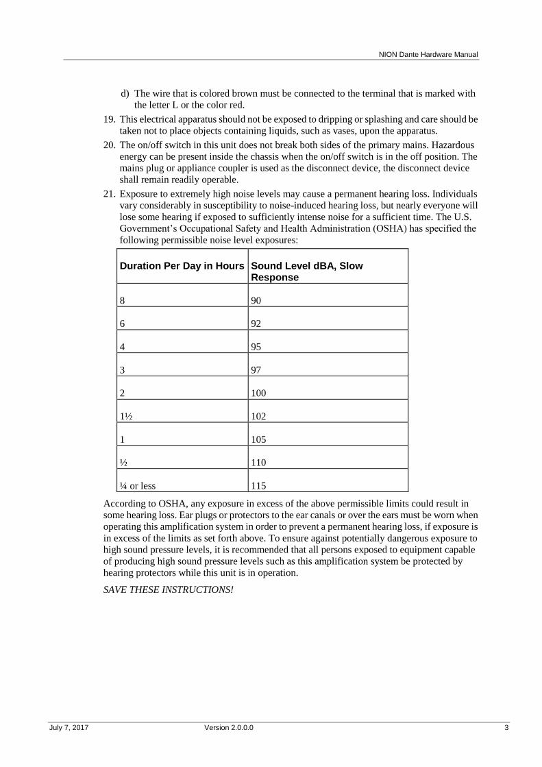
21. Exposure to extremely high noise levels may cause a permanent hearing loss. Individuals
vary considerably in susceptibility to noise-induced hearing loss, but nearly everyone will
lose some hearing if exposed to sufficiently intense noise for a sufficient time. The U.S.
Government’s Occupational Safety and Health Administration (OSHA) has specified the
following permissible noise level exposures:
Duration Per Day in Hours Sound Level dBA, Slow Response
8 90
6 92
4 95
3 97
2 100
1½ 102
1 105
½ 110
¼ or less 115
According to OSHA, any exposure in excess of the above permissible limits could result in
some hearing loss. Ear plugs or protectors to the ear canals or over the ears must be worn when
operating this amplification system in order to prevent a permanent hearing loss, if exposure is
in excess of the limits as set forth above. To ensure against potentially dangerous exposure to
high sound pressure levels, it is recommended that all persons exposed to equipment capable
of producing high sound pressure levels such as this amplification system be protected by
hearing protectors while this unit is in operation.
SAVE THESE INSTRUCTIONS!


July 7, 2017 Version 2.0.0.0 5
In This Chapter
Important network considerations ..................................................................... 6
Power outage and surge protection ................................................................... 6
Thank You! ....................................................................................................... 6
Warranty Registration ....................................................................................... 6
What's in the box? ............................................................................................. 6
Chapte r 2
Before you start
Chapter 2 - Before you start
6 Version 2.0.0.0 July 7, 2017
.
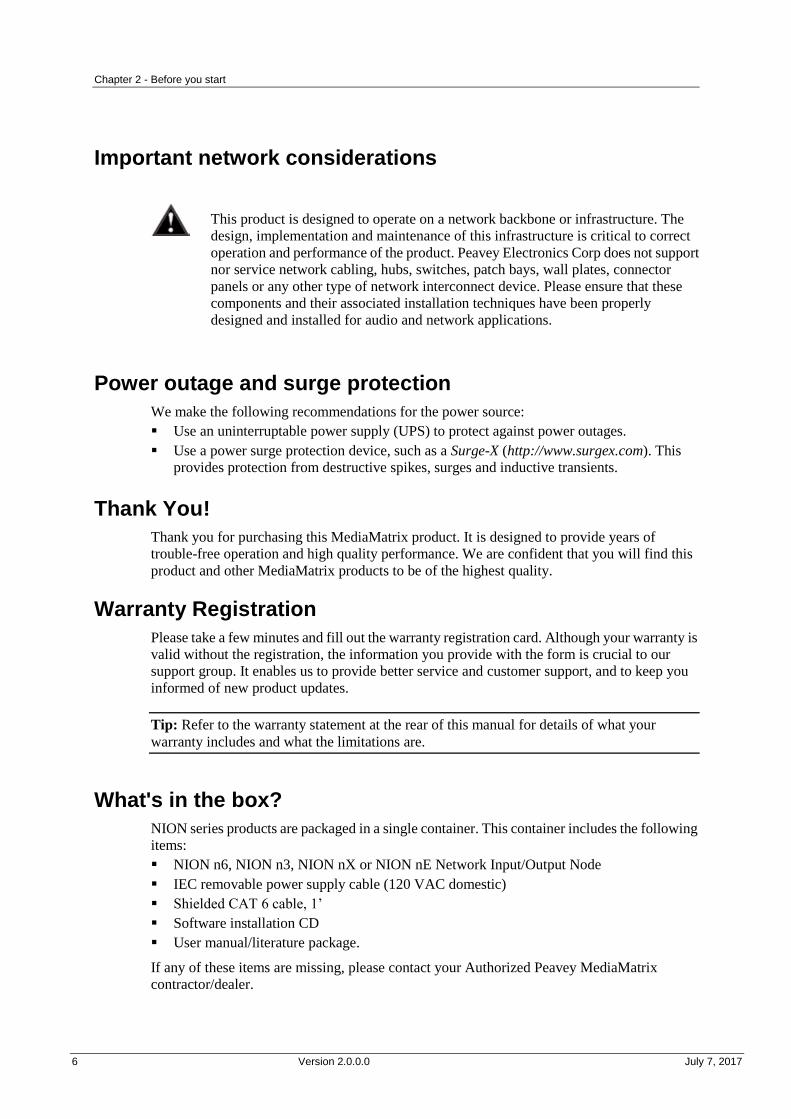
Important network considerations
This product is designed to operate on a network backbone or infrastructure. The
design, implementation and maintenance of this infrastructure is critical to correct
operation and performance of the product. Peavey Electronics Corp does not support
nor service network cabling, hubs, switches, patch bays, wall plates, connector
panels or any other type of network interconnect device. Please ensure that these
components and their associated installation techniques have been properly
designed and installed for audio and network applications.
Power outage and surge protection
We make the following recommendations for the power source:
Use an uninterruptable power supply (UPS) to protect against power outages.
Use a power surge protection device, such as a Surge-X (http://www.surgex.com). This
provides protection from destructive spikes, surges and inductive transients.
Thank You!
Thank you for purchasing this MediaMatrix product. It is designed to provide years of
trouble-free operation and high quality performance. We are confident that you will find this
product and other MediaMatrix products to be of the highest quality.
Warranty Registration
Please take a few minutes and fill out the warranty registration card. Although your warranty is
valid without the registration, the information you provide with the form is crucial to our
support group. It enables us to provide better service and customer support, and to keep you
informed of new product updates.
Tip: Refer to the warranty statement at the rear of this manual for details of what your
warranty includes and what the limitations are.
What's in the box?
NION series products are packaged in a single container. This container includes the following
items:
NION n6, NION n3, NION nX or NION nE Network Input/Output Node
IEC removable power supply cable (120 VAC domestic)
Shielded CAT 6 cable, 1’
Software installation CD
User manual/literature package.
If any of these items are missing, please contact your Authorized Peavey MediaMatrix
contractor/dealer.
July 7, 2017 Version 2.0.0.0 7
In This Chapter
Description ........................................................................................................ 8
Features ............................................................................................................. 8
Applications ...................................................................................................... 9
Cards ................................................................................................................. 10
Front Panel ........................................................................................................ 12
Rear panel ......................................................................................................... 13
Network services ............................................................................................... 14
Chapte r 3
Introduction to NION

Chapter 3 - Introduction to NION
8 Version 2.0.0.0 July 7, 2017
.
Description
NION is a programmable digital audio processing node designed for professional and
commercial audio and communications applications.
The product features an internal processing core supported by a wide range of features,
including a scalable I/O architecture. A range of plug-in cards is available that allow audio
input and output, plus advanced features like echo cancellation.
Audio network connectivity is provided by the integrated Dante DLM module.
NIONs are managed centrally using NWare. You can also specify configuration settings using
the web interface or front panel interface (fitted to all models apart from the nE).
Additional control interfacing is provided by both RS-232 and RS-422/485 ports, while a
configurable GPIO system allows interfacing with hard contacts and logic systems.
Note: If you are intending to use a NION to host a Kiosk2Go project, it is important that the
compact flash (CF) memory card is of sufficient capacity. If the NION is fitted with a 256MB
card, you may find problems with the display of more complex Kiosk2Go projects in the
browser. We recommend that the compact flash card is replaced with a higher capacity
version. To check the capacity of the CF memory card, navigate to the NION web interface,
then click Hardware. The capacity is displayed under Memory, as CFA: xxx meg. For more
information, contact MediaMatrix Technical Support (mailto:[email protected]).
Features
Floating point DSP Engine with 6 DSP
chips (NION n6) or 3 DSP chips (NION
n3, NION nX and NION nE)
Front panel interface with intuitive user
input controls (n3, n6 and nX models
only)
World-famous MediaMatrix audio
algorithms
Robust Linux embedded system
controller
64 channels of audio I/O via integrated
Dante interface.
Integrated flash-based storage
32 channels of audio I/O via 8 four
channel cards.
Supports optional hard-disk storage
systems
32 bit processing engine Windows configuration and control client
24 bit conversion Full support for SNMP network
management tools
XDAB bus (NION n3, NION n6)
supports up to 448 bi-directional audio
channels
Universal industrial-grade power supply
Low latency audio performance Software support for large-scale
multi-node systems
Network-centric architecture Advanced DSP compiler
Supports centralized, distributed or
hybrid processing
Configurable GPIO with DIN rail
package
Integrated serial support Transparent control grouping across
NION Dante Hardware Manual
July 7, 2017 Version 2.0.0.0 9
physical nodes
Supports sample rates of 48 kHz and 96
kHz
Supports redundant, self-healing
configurations
Standalone or combined operation
Applications
Stadiums
Auditoriums
Arenas
Civic centers
Performing arts centers
Theaters
Courts of law
Houses of worship
Campus buildings
Theme parks
Hotel meeting rooms
Conference centers
Schools
Cruise ships
Teleconferencing
Distance learning
Large-scale paging
Multi-purpose facilities
Retail
Restaurants & bars
Gaming
Institutional paging
Communications
Correctional facilities
Professional complexes
Residential.

Chapter 3 - Introduction to NION
10 Version 2.0.0.0 July 7, 2017
.
Cards
All the different types of cards can be installed in any of the available expansion slots at the
rear of the NION.
NIO-4x4
Four analog mic/line level audio input channels
Four analog line level audio output channels
24 bit A/D (inputs), 24 bit D/A (outputs)
48 or 96 kHz audio sampling rate supported
High reliability DIN connector to backplane, using slide rail for alignment
Mini-Euro connectors for easy input connection.
NIO-8ml II
Eight analog mic/line level audio input channels
24 bit A/D (inputs)
48 or 96 kHz audio sampling rate supported
High reliability DIN connector to backplane, using slide rail for alignment
Mini-Euro connectors for easy input connection.
NIO-8i
Eight analog line level audio input channels
24 bit A/D (inputs)
48 or 96 kHz audio sampling rate supported
High reliability DIN connector to backplane, using slide rail for alignment
Mini-Euro connectors for easy input connection.
NIO-8o
Eight analog line level audio output channels
24 bit A/D (outputs)
48 or 96 kHz audio sampling rate supported
High reliability DIN connector to backplane, using slide rail for alignment
Mini-Euro connectors for easy input connection.
NIO-AEC
Eight analog mic/line-level audio input channels with 24 bit A/D
Eight channels of wideband acoustic echo cancellation
Acoustic echo cancellation can be applied to mic input or internal audio input channels
(from NION)
48 or 96 kHz audio sampling rate supported

NION Dante Hardware Manual
July 7, 2017 Version 2.0.0.0 11
High reliability DIN connector to backplane, using slide rail for alignment
Mini-Euro connectors for easy input connection.
NIO-AES
Eight channel pairs of AES3 input or output audio channels
Input or output channel pairs may be selected individually in software
S/PDIF supported and enabled with onboard dip switches
Sample rate converters defeatable in the NWare control software
48 or 96 kHz audio sampling rate supported
High reliability DIN connector to backplane, using slide rail for alignment
Mini-Euro connectors for easy input connection.
Chapter 3 - Introduction to NION
12 Version 2.0.0.0 July 7, 2017
.
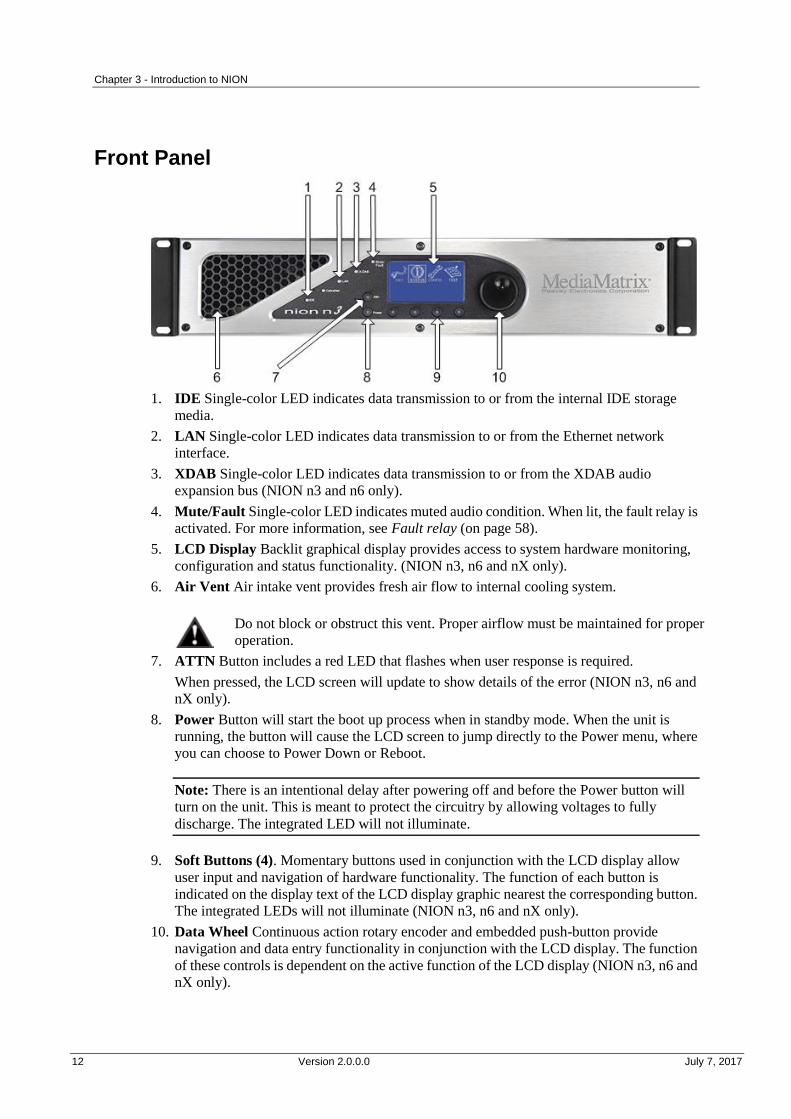
Front Panel
1. IDE Single-color LED indicates data transmission to or from the internal IDE storage
media.
2. LAN Single-color LED indicates data transmission to or from the Ethernet network
interface.
3. XDAB Single-color LED indicates data transmission to or from the XDAB audio
expansion bus (NION n3 and n6 only).
4. Mute/Fault Single-color LED indicates muted audio condition. When lit, the fault relay is
activated. For more information, see Fault relay (on page 58).
5. LCD Display Backlit graphical display provides access to system hardware monitoring,
configuration and status functionality. (NION n3, n6 and nX only).
6. Air Vent Air intake vent provides fresh air flow to internal cooling system.
Do not block or obstruct this vent. Proper airflow must be maintained for proper
operation.
7. ATTN Button includes a red LED that flashes when user response is required.
When pressed, the LCD screen will update to show details of the error (NION n3, n6 and
nX only).
8. Power Button will start the boot up process when in standby mode. When the unit is
running, the button will cause the LCD screen to jump directly to the Power menu, where
you can choose to Power Down or Reboot.
Note: There is an intentional delay after powering off and before the Power button will
turn on the unit. This is meant to protect the circuitry by allowing voltages to fully
discharge. The integrated LED will not illuminate.
9. Soft Buttons (4). Momentary buttons used in conjunction with the LCD display allow
user input and navigation of hardware functionality. The function of each button is
indicated on the display text of the LCD display graphic nearest the corresponding button.
The integrated LEDs will not illuminate (NION n3, n6 and nX only).
10. Data Wheel Continuous action rotary encoder and embedded push-button provide
navigation and data entry functionality in conjunction with the LCD display. The function
of these controls is dependent on the active function of the LCD display (NION n3, n6 and
nX only).

NION Dante Hardware Manual
July 7, 2017 Version 2.0.0.0 13
Rear panel
1. Serial Port Female DB-9 panel connector, which provides RS-232 communications for
external control protocols.
Note: On earlier units, this connector is on the front panel.
2. Power Receptacle Flush-mount IEC power receptacle for connecting a compatible IEC
power cable (included).
Use only the supplied cable or an equivalent international version.
3. Module Bays Housing bays for NION series expansion cards. Up to 4 Nio series I/O cards
can be installed.
4. Power Supply Industrial ATX format power supply with exhaust fan.
Additional air flow is provided on the side panel opposite the power supply. Install
with at least 2” of free clearance on sides of unit. Do not block any air intake or
exhaust vent.
5. XDAB In/Out RJ-45 connectors accept shielded CAT6 data cables for proprietary NION
interconnect system.
6. GPIO Female DB-25 panel connector provides access to the internal GPIO control
functionality.
7. LAN RJ-45 panel connector accepts a CAT5 data cable for data transport to/from the
internal network interface. This connection is required on all units for system
configuration and inter-unit communications.
8. RS-485/422 Female DB-9 panel connector accepts a standard DB-9 connector (not
included) to provide access to the external RS-485 or RS-422 external control protocols.
9. Dante network I/O ports Two RJ-45 connectors providing a primary and secondary
interface to the Dante network. One connection is required to pass audio to or from the
device. The second connection provides redundancy.
Chapter 3 - Introduction to NION
14 Version 2.0.0.0 July 7, 2017
Note: The secondary port does not provide additional network capacity and only becomes
active in the event that the network connected to the primary port becomes inoperative.
Network services
Web
Each NION includes a built-in web server that provides access to several key hardware
functions from any web browser.
Telnet
Telnet is a communications protocol that provides access to the Linux system kernel on the
NION.
Note: For security reasons, you should only enable the Telnet function when asked to by
MediaMatrix Technical Support. Once you have finished communicating with the NION, you
should disable the Telnet function. Telnet is not required for communications with the NWare
software or for using RATC.
SNMP
Simple Network Management Protocol is a network protocol that provides robust monitoring
and control of system parameters across the network. Using SNMP, you can utilize a host of
standard software tools and third-party systems to extend the control and monitoring power of
the NION for a wide variety of applications.
FTP
File Transfer Protocol. A standard network protocol used for transferring files over a TCP
network. Each NION, nControl and nTouch 180 has a built-in FTP server.

July 7, 2017 Version 2.0.0.0 15
In This Chapter
Introduction ....................................................................................................... 16
What you will need ........................................................................................... 16
Test configuration ............................................................................................. 17
Configuring your PC for connecting to a NION nE ......................................... 17
Connections....................................................................................................... 18
Chapte r 4
Installing the NION
Chapter 4 - Installing the NION
16 Version 2.0.0.0 July 7, 2017
.
Introduction
The NION is designed to mount in a standard EIA electronic equipment rack. Because the
NION includes forced air cooling, rack mounted vent panels are not required for most
installations. However, vent panels may be required in large installations where multiple units
are mounted in a single rack. It is generally accepted that a ratio of 2:1 usually provides
adequate performance. In installations where adverse conditions exist, and room temperatures
are likely to rise, additional vents should be installed.
This product should be installed so that its mounting position does not interfere
with proper ventilation. Do not block air intake or exhaust vents.
The power switch in this unit does not break both sides of the primary mains.
Hazardous energy can be present inside the chassis when the power switch is in the
off position. The mains plug or appliance coupler is used as the disconnect device,
the disconnect device shall remain readily operable.
What you will need
A MediaMatrix NION with Dante DLM fitted.
The latest Dante Controller software. (Updates can be downloaded from the Audinate
website (http://www.audinate.com).)
The latest NWare software. (Updates can be downloaded from the MediaMatrix website
(http://www.peaveycommercialaudio.com/products.cfm/Software/NWare-Software/NWar
e-Software).)
A computer running Microsoft Windows, with monitor, mouse and keyboard.
An assortment of CAT 5e or CAT 6 cables.
At least one NIO series analog audio input card.
At least one NIO series analog audio output card.
Tip: The NIO-4x4 card supports both analog audio inputs and outputs on the same card.
This card can be used in place of an input card and an output card.
An audio source, cables, power amplifier and loudspeaker.
A small Phillips screwdriver.
A small flat-blade screwdriver.
A network switch connected to the Dante network.
Note: Dante uses standard Voice over IP (VoIP) Quality of Service (QoS) switch features
to prioritize clock sync and audio traffic over other network traffic. QoS is available in
many inexpensive and enterprise Ethernet switches. Any switch that supports Diffserv
(DSCP) QoS with strict priority and 4 queues, and has Gigabit ports for inter-switch
connections should be appropriate for use with Dante, but we recommend that you check
the Q&A section on the Audinate website (http://www.audinate.com) for details of any
other requirements.
NION Dante Hardware Manual
July 7, 2017 Version 2.0.0.0 17
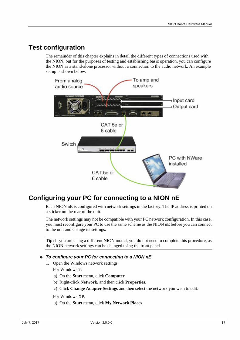
Test configuration
The remainder of this chapter explains in detail the different types of connections used with
the NION, but for the purposes of testing and establishing basic operation, you can configure
the NION as a stand-alone processor without a connection to the audio network. An example
set up is shown below.
Configuring your PC for connecting to a NION nE
Each NION nE is configured with network settings in the factory. The IP address is printed on
a sticker on the rear of the unit.
The network settings may not be compatible with your PC network configuration. In this case,
you must reconfigure your PC to use the same scheme as the NION nE before you can connect
to the unit and change its settings.
Tip: If you are using a different NION model, you do not need to complete this procedure, as
the NION network settings can be changed using the front panel.
To configure your PC for connecting to a NION nE
1. Open the Windows network settings.
For Windows 7:
a) On the Start menu, click Computer.
b) Right-click Network, and then click Properties.
c) Click Change Adapter Settings and then select the network you wish to edit. a)
For Windows XP:
a) On the Start menu, click My Network Places.
Chapter 4 - Installing the NION
18 Version 2.0.0.0 July 7, 2017
b) Click View Network Connections.
1. Configure the PC with an IP address in the same subnet as is printed on the while sticker
on the back of the NION nE. For example, if the sticker shows 10.7.5.75, then your
computer's IP address will be 10.7.5.x where x is any value below 75, such as 10.7.5.66.
2. Set the subnet mask to 255.255.255.0.
Connections
Dante network connection
The first priority is the Dante network connection. The RJ-45 connectors on the Dante
interface are designed to connect with standard, off-the-shelf Category 5e or 6 cable for use
with standard Ethernet network switches.
Notes:
The network must be properly designed for each system. If you lack experience in
networking, we suggest that you partner with someone with networking experience.
Gigabit switches are recommended.
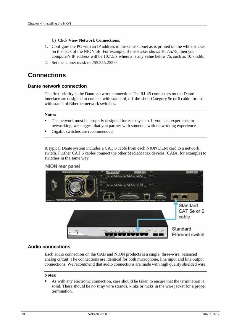
A typical Dante system includes a CAT 6 cable from each NION DLM card to a network
switch. Further CAT 6 cables connect the other MediaMatrix devices (CABs, for example) to
switches in the same way.
Audio connections
Each audio connection on the CAB and NION products is a single, three-wire, balanced
analog circuit. The connections are identical for both microphone, line input and line output
connections. We recommend that audio connections are made with high quality shielded wire.
Notes:
As with any electronic connection, care should be taken to ensure that the termination is
solid. There should be no stray wire strands, kinks or nicks in the wire jacket for a proper
termination.
NION Dante Hardware Manual
July 7, 2017 Version 2.0.0.0 19
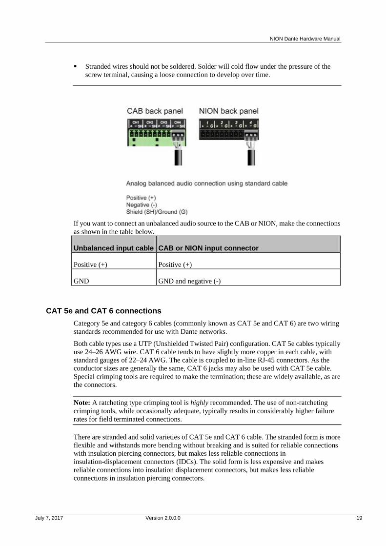
Stranded wires should not be soldered. Solder will cold flow under the pressure of the
screw terminal, causing a loose connection to develop over time.
If you want to connect an unbalanced audio source to the CAB or NION, make the connections
as shown in the table below.
Unbalanced input cable CAB or NION input connector
Positive (+) Positive (+)
GND GND and negative (-)
CAT 5e and CAT 6 connections
Category 5e and category 6 cables (commonly known as CAT 5e and CAT 6) are two wiring
standards recommended for use with Dante networks.
Both cable types use a UTP (Unshielded Twisted Pair) configuration. CAT 5e cables typically
use 24–26 AWG wire. CAT 6 cable tends to have slightly more copper in each cable, with
standard gauges of 22–24 AWG. The cable is coupled to in-line RJ-45 connectors. As the
conductor sizes are generally the same, CAT 6 jacks may also be used with CAT 5e cable.
Special crimping tools are required to make the termination; these are widely available, as are
the connectors.
Note: A ratcheting type crimping tool is highly recommended. The use of non-ratcheting
crimping tools, while occasionally adequate, typically results in considerably higher failure
rates for field terminated connections.
There are stranded and solid varieties of CAT 5e and CAT 6 cable. The stranded form is more
flexible and withstands more bending without breaking and is suited for reliable connections
with insulation piercing connectors, but makes less reliable connections in
insulation-displacement connectors (IDCs). The solid form is less expensive and makes
reliable connections into insulation displacement connectors, but makes less reliable
connections in insulation piercing connectors.

Chapter 4 - Installing the NION
20 Version 2.0.0.0 July 7, 2017
When used for 10/100/1000BASE-T, the maximum allowed length of a CAT 5e or CAT 6
cable is 100 meters or 328 feet. This consists of 90 meters (300 ft) of solid horizontal cabling
between the patch panel and the wall jack, plus 10 meters (33 ft) of stranded patch cable
between each jack and the attached device. Since stranded cable has higher attenuation than
solid cable, exceeding 10 metres of patch cabling will reduce the permissible length of
horizontal cable.
Different types of connectors are used with either type of wire. There is a bent tine connector
intended for use with solid core wire, and an aligned tine connector for use with stranded
cable. The bent tine connector will generally work on stranded wire, but not the other way
around.
All cable types must be properly installed and terminated to meet specifications. The cable
must not be kinked or bent too tightly (the bend radius should be at least four times the outer
diameter of the cable). The wire pairs must not be untwisted and the outer jacket must not be
stripped back more than 1/2 inch (1.27 cm).
There are two main standards for termination: T568A and T568B. For more information on
the wiring for these standards, see Wikipedia
(http://en.wikipedia.org/wiki/T568A#T568A_and_T568B_termination).
Notes:
A single CAT 5e or CAT6 cable run must not exceed 100 meters.
Make sure your connector matches your cable type. If you are not sure, use the bent tine
variety.
When terminating CAT 5e or CAT6 cable, it is important that the natural twist of each pair
is carried through as close as possible to the point of termination at the connector.
We recommend that you familiarize yourself with the wiring color schemes so they are
second nature to you. An error in the cabling of an Ethernet network is often the primary
cause of system errors.
It is very important that you build the cable with all pairs properly terminated. This will
prevent any confusion later, and give your cable a solid mechanical connection.
The use of pre-made and pre-tested cabling can greatly simplify and expedite installation
for wiring within a rack.
There are two main standards for termination: T568A and T568B. It is important that both
ends of a cable are terminated in line with one of these standards and you do not use one
standard for one end of the cable and the other for the other end. The cable will not
function normally.
Rotary encoder connection
NION and CAB products include a versatile GPIO (General Purpose Input Output) system at
the rear for terminating external logic, controls, relays and other external systems. This port is
used when you want to connect a rotary encoder device to the NION. Up to eight rotary
encoders can be connected to a single NION. They are supported by all variants of the NION.
Connect the rotary encoder to the GPIO port on the rear of the NION using three pins. Several
GPIO pins perform the same function, so you can choose from a number of pins for each.
NION GPIO pin Rotary encoder pin
10, 11, 22, or 23 Common
NION Dante Hardware Manual
July 7, 2017 Version 2.0.0.0 21
2, 4, 6, 8, 14, 16, 18, or 20 2nd pin
3, 5, 7, 9, 15, 17, 19, or 21 3rd pin
Note: The rotary encoder may also have connections for a push button, as well as a rotary
mechanism. You must use the pins associated with the rotary mechanism only.
When you are designing your project and you add a NION to your NWare design, select the
following functions for the GPIO pins:
Pin 10, 11, 22, or 23 set as HCO (High Current Out) +12VDC.
Pins 2, 4, 6, 8, 14, 16, 18, or 20 set as Rotary Encoder.
Pin 3, 5, 7, 9, 15, 17, 19, or 21 set as Unused.
For information on the GPIO controls for the NION device in NWare, see GPIO in the NWare
Device Reference.
Serial port connections
The diagram below shows the types of serial connections supported by the ports at the rear of
the NION.
The NION RS-232 serial port performs two main functions:
In console mode it allows a user to log on to the NION Linux Kernel via a serial terminal
session and change the configuration settings.
When console mode is disabled, you can control the NION using external protocols like
PASHA.
By default, console mode on the NION RS-232 serial port is disabled.

Chapter 4 - Installing the NION
22 Version 2.0.0.0 July 7, 2017
The RS-485 serial port can be used to communicate with external devices in the same way as
the RS-232 port, and using the same protocols, but cannot be used for serial terminal
connections to the NION.

July 7, 2017 Version 2.0.0.0 23
In This Chapter
Configuration steps ........................................................................................... 24
Using the front panel ......................................................................................... 25
Using the web interface .................................................................................... 33
Updating the firmware ...................................................................................... 47
Using XDAB to share DSP resources ............................................................... 47
What to do next ................................................................................................. 48
Chapte r 5
Setting up the NION

Chapter 5 - Setting up the NION
24 Version 2.0.0.0 July 7, 2017
.
Configuration steps
Once you have physically installed and connected the NION (as described in Installing the
NION), follow the procedures below to configure it with the most important settings.
If the NION has a front panel, you can use this to specify the settings. If the NION is not fitted
with a front panel (it is a NION nE), you will need to connect to it using the IP address printed
on a sticker on the rear of the unit.
To configure a NION with a front panel
1. Specify a name for the NION (on page 26).
2. Specify an IP address for the control network (on page 26).
3. Check that the interfaces you want to use are enabled (on page 29).
4. Open a web browser, connect to the NION on the control network, then set the time and
date (on page 37).
To configure a NION without a front panel
1. Open a web browser, connect to the NION using its IP address, then configure the network
settings (on page 33).
2. Specify a name for the NION (on page 35).
3. Check that the interfaces you want to use are enabled.
4. Set the time and date (on page 37).

NION Dante Hardware Manual
July 7, 2017 Version 2.0.0.0 25
.
Using the front panel
The front panel interface
The front panel interface includes an LCD display, four context-sensitive soft buttons, two
fixed function buttons and a data wheel with integrated push button. Basic navigation is
accomplished with the soft buttons and the wheel, while the wheel’s push button is used to
select and confirm settings. Each page in the NION interface is accessible in sequence,
controlled by the PREV and NEXT soft buttons. To confirm a setting, use the OK soft button.
To cancel an operation, use the CANCEL soft button.
The cursor type indicates the action and position. An outlined cursor indicates the current
cursor position. A solid filled cursor indicates a selection. Once a cursor position is selected,
the wheel allows you to change a value at the current position. Pressing the wheel button
confirms the setting.
The sections that follow describe how to change settings in the CONFIG menu. This menu is
available from the Home page.
Tip: If you are viewing a different screen, you can select the HOME option to return to the
home page.
Note: If security has been enabled, you will need to specify a password before you can change
any of the settings.
Chapter 5 - Setting up the NION
26 Version 2.0.0.0 July 7, 2017
Specifying a name
Each NION has a name that is displayed in the web interface, on the front panel (if fitted) and
in NWare and Dante Controller.
In the factory, an identical name is given to every NION. Therefore, in order to identify
individual units by their names, you must assign a unique name to each unit. The name is also
used to identify Dante transmitters and receivers in Dante Controller.
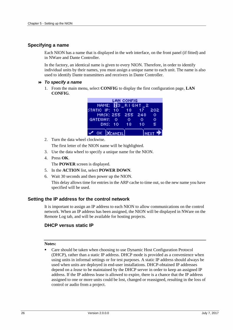
To specify a name
1. From the main menu, select CONFIG to display the first configuration page, LAN
CONFIG.
2. Turn the data wheel clockwise.
The first letter of the NION name will be highlighted.
3. Use the data wheel to specify a unique name for the NION.
4. Press OK.
The POWER screen is displayed.
5. In the ACTION list, select POWER DOWN.
6. Wait 30 seconds and then power up the NION.
This delay allows time for entries in the ARP cache to time out, so the new name you have
specified will be used.
Setting the IP address for the control network
It is important to assign an IP address to each NION to allow communications on the control
network. When an IP address has been assigned, the NION will be displayed in NWare on the
Remote Log tab, and will be available for hosting projects.
DHCP versus static IP
Notes:
Care should be taken when choosing to use Dynamic Host Configuration Protocol
(DHCP), rather than a static IP address. DHCP mode is provided as a convenience when
using units in informal settings or for test purposes. A static IP address should always be
used when units are deployed in end-user installations. DHCP-obtained IP addresses
depend on a lease to be maintained by the DHCP server in order to keep an assigned IP
address. If the IP address lease is allowed to expire, there is a chance that the IP address
assigned to one or more units could be lost, changed or reassigned, resulting in the loss of
control or audio from a project.

NION Dante Hardware Manual
July 7, 2017 Version 2.0.0.0 27
The network administrator should be able to give you a range of static (or fixed) IP
addresses to use for your project. When requesting these IP addresses, be sure to obtain
enough to cover each unit.
Using DHCP to assign an IP address automatically
1. Confirm that the network to which you are connecting the unit has a DHCP server.
Notes:
If DHCP mode is selected, but there is no DHCP server on the network, the unit will
be unable to communicate with other devices.
In this example, the DHCP server is provided by the router. Ensure that your network
is using a router. A plain switch will not provide the required DHCP server for the
example.
2. From the main menu, select CONFIG to display the first configuration page, LAN
CONFIG.
3. Move the cursor to the second line, next to IP.
4. Push the wheel button, then move the wheel until the cursor position indicates DHCP,
then push the wheel button again to confirm the settings.
Chapter 5 - Setting up the NION
28 Version 2.0.0.0 July 7, 2017
Tips:
Since DHCP is being used, there is no need to specify an IP address, subnet mask or
gateway - they are automatically assigned by the DHCP process.
If a DNS is set up on the network and DHCP has been configured to contact the DNS,
the DNS field will be populated automatically with the IP address of the DNS. NION
uses the DNS to resolve the domain names of time servers. For more information, see
Setting up a NION as a master.
5. Select NEXT to advance to the next page, or OK to confirm the settings and exit.
To abort the process, select CANCEL.
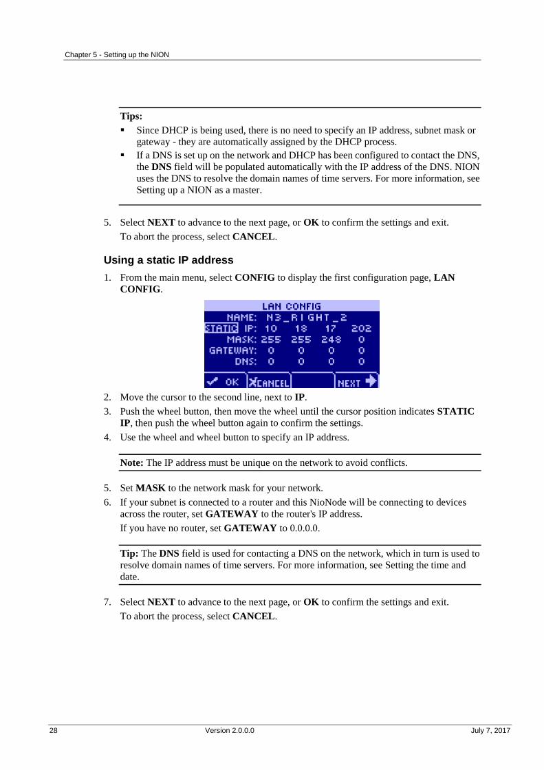
Using a static IP address
1. From the main menu, select CONFIG to display the first configuration page, LAN
CONFIG.
2. Move the cursor to the second line, next to IP.
3. Push the wheel button, then move the wheel until the cursor position indicates STATIC
IP, then push the wheel button again to confirm the settings.
4. Use the wheel and wheel button to specify an IP address.
Note: The IP address must be unique on the network to avoid conflicts.
5. Set MASK to the network mask for your network.
6. If your subnet is connected to a router and this NioNode will be connecting to devices
across the router, set GATEWAY to the router's IP address.
If you have no router, set GATEWAY to 0.0.0.0.
Tip: The DNS field is used for contacting a DNS on the network, which in turn is used to
resolve domain names of time servers. For more information, see Setting the time and
date.
7. Select NEXT to advance to the next page, or OK to confirm the settings and exit.
To abort the process, select CANCEL.
NION Dante Hardware Manual
July 7, 2017 Version 2.0.0.0 29
Dante network settings
On Dante networks, an IP address is assigned automatically to each NION using DHCP. You
do not need to specify an address manually using the front panel.
Note: The IP address of a NION cannot be viewed on the front panel display, but the IP
addresses of each MediaMatrix device can be viewed on the Device Status tab in Dante
Controller.
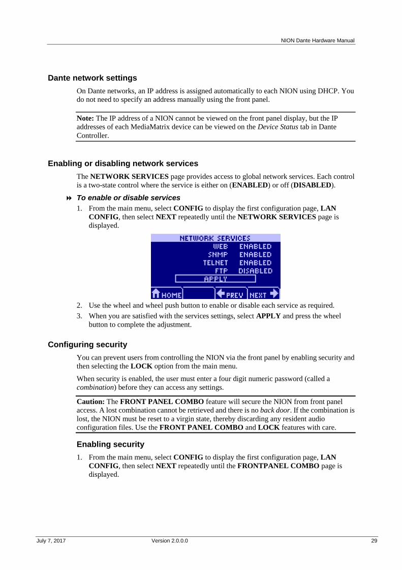
Enabling or disabling network services
The NETWORK SERVICES page provides access to global network services. Each control
is a two-state control where the service is either on (ENABLED) or off (DISABLED).
To enable or disable services
1. From the main menu, select CONFIG to display the first configuration page, LAN
CONFIG, then select NEXT repeatedly until the NETWORK SERVICES page is
displayed.
2. Use the wheel and wheel push button to enable or disable each service as required.
3. When you are satisfied with the services settings, select APPLY and press the wheel
button to complete the adjustment.
Configuring security
You can prevent users from controlling the NION via the front panel by enabling security and
then selecting the LOCK option from the main menu.
When security is enabled, the user must enter a four digit numeric password (called a
combination) before they can access any settings.
Caution: The FRONT PANEL COMBO feature will secure the NION from front panel
access. A lost combination cannot be retrieved and there is no back door. If the combination is
lost, the NION must be reset to a virgin state, thereby discarding any resident audio
configuration files. Use the FRONT PANEL COMBO and LOCK features with care.
Enabling security
1. From the main menu, select CONFIG to display the first configuration page, LAN
CONFIG, then select NEXT repeatedly until the FRONTPANEL COMBO page is
displayed.

Chapter 5 - Setting up the NION
30 Version 2.0.0.0 July 7, 2017
2. Using the wheel and the wheel push button, move the cursor to each NEW COMBO field
and select a number to specify the new combination.
3. Move the selection to APPLY and press the wheel push button.
Locking the front panel
1. From the main menu, move the cursor to the LOCK icon and use the wheel push button to
enter the LOCK screen.
2. Use the wheel and the wheel push button to enter the combination.
3. Move the cursor to LOCK and push the wheel’s push button to engage security, or select
CANCEL to abort the process.
Caution: Once the front panel is locked, it will not be possible to use the functions of the
NION until the correct combination has been entered. There is no back door.
Disabling security
1. From the main menu, select CONFIG to display the first configuration page, LAN
CONFIG, then select NEXT repeatedly until the FRONTPANEL COMBO page is
displayed.
NION Dante Hardware Manual
July 7, 2017 Version 2.0.0.0 31
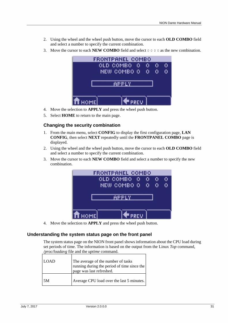
2. Using the wheel and the wheel push button, move the cursor to each OLD COMBO field
and select a number to specify the current combination.
3. Move the cursor to each NEW COMBO field and select 0 0 0 0 as the new combination.
4. Move the selection to APPLY and press the wheel push button.
5. Select HOME to return to the main page.
Changing the security combination
1. From the main menu, select CONFIG to display the first configuration page, LAN
CONFIG, then select NEXT repeatedly until the FRONTPANEL COMBO page is
displayed.
2. Using the wheel and the wheel push button, move the cursor to each OLD COMBO field
and select a number to specify the current combination.
3. Move the cursor to each NEW COMBO field and select a number to specify the new
combination.
4. Move the selection to APPLY and press the wheel push button.
Understanding the system status page on the front panel
The system status page on the NION front panel shows information about the CPU load during
set periods of time. The information is based on the output from the Linux Top command,
/proc/loadavg file and the uptime command.
LOAD The average of the number of tasks
running during the period of time since the
page was last refreshed.
5M Average CPU load over the last 5 minutes.

Chapter 5 - Setting up the NION
32 Version 2.0.0.0 July 7, 2017
15M Average CPU load over the last 15
minutes.
CPU Current percentage utilization of the CPU.
For more information on the Top command, see http://linux.die.net/man/1/top
(http://linux.die.net/man/1/top).
For more information on the /proc/loadavg file and the uptime command, see to www.luci.org
(http://www.luci.org/luci-discuss/200210/msg00055.html).
Adjusting the LCD backlight intensity and viewing angle
The LCD CONFIG page allows you to adjust the LCD backlight intensity and the viewing
angle.
The perceived contrast is dependent on the viewing position. For example, a setting that
provides high contrast when viewing the display from the front, may provide an inverted view
when looking at the display from above. Adjust for the best view at the common working
angle.
To adjust the LCD backlight intensity and viewing angle
1. From the main menu, select CONFIG to display the first configuration page, LAN
CONFIG, then select NEXT repeatedly until the LCD CONFIG page is displayed.
2. Use the wheel and push button to select LCD BACKLIGHT.
3. Use the wheel’s rotary control to select the desired value.
The range is 0 (least intense) to 15 (most intense).
4. Use the wheel and push button to select VIEWING ANGLE.
5. Use the wheel’s rotary control to select the desired value.
The range is 10 to 40 with the 20 position providing the highest contrast and color when
viewing the display head on or directly in front.
6. When you are satisfied with the display settings, select NEXT to advance or HOME to
complete the adjustment.
Viewing the audio meters for input and output cards
You can view the input levels and output levels for the different channels on each of the cards
installed in the NION.
Note: The audio meters do not display input and output levels for NIO-AES cards.

NION Dante Hardware Manual
July 7, 2017 Version 2.0.0.0 33
To view the audio meters for input and output cards
1. From the main menu, select METERS.
The meters for the card in slot 1 are shown first. A plot is shown for each audio channel.
Inputs are prefixed with I, and outputs are prefixed with O. Here is an example showing a
NIO-4x4 card in slot 2.
2. If you want to view the meters for another card, turn the data wheel on the front panel.
Using the web interface
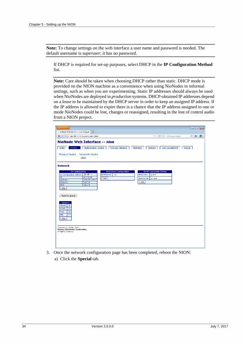
Specifying the IP address via the web browser
1. Open a web browser and enter the NION IP address into the web address bar.
2. Click the Network tab.
If a different static IP address is required then:
a) Make sure that static is selected in the IP Configuration Method list.
b) Fill in IP address and netmask value appropriate to your network. The Gateway and
DNS entries can also be entered if required.
Chapter 5 - Setting up the NION
34 Version 2.0.0.0 July 7, 2017
Note: To change settings on the web interface a user name and password is needed. The
default username is superuser; it has no password.
If DHCP is required for set-up purposes, select DHCP in the IP Configuration Method
list.
Note: Care should be taken when choosing DHCP rather than static. DHCP mode is
provided on the NION machine as a convenience when using NioNodes in informal
settings, such as when you are experimenting. Static IP addresses should always be used
when NioNodes are deployed in production systems. DHCP-obtained IP addresses depend
on a lease to be maintained by the DHCP server in order to keep an assigned IP address. If
the IP address is allowed to expire there is a chance that the IP address assigned to one or
mode NioNodes could be lost, changes or reassigned, resulting in the lost of control audio
from a NION project.
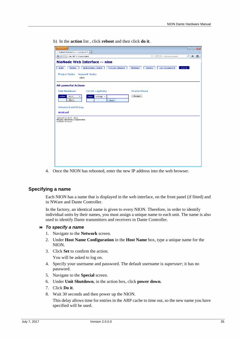
3. Once the network configuration page has been completed, reboot the NION:
a) Click the Special tab.
NION Dante Hardware Manual
July 7, 2017 Version 2.0.0.0 35
b) In the action list , click reboot and then click do it.
4. Once the NION has rebooted, enter the new IP address into the web browser.
Specifying a name
Each NION has a name that is displayed in the web interface, on the front panel (if fitted) and
in NWare and Dante Controller.
In the factory, an identical name is given to every NION. Therefore, in order to identify
individual units by their names, you must assign a unique name to each unit. The name is also
used to identify Dante transmitters and receivers in Dante Controller.
To specify a name
1. Navigate to the Network screen.
2. Under Host Name Configuration in the Host Name box, type a unique name for the
NION.
3. Click Set to confirm the action.
You will be asked to log on.
4. Specify your username and password. The default username is superuser; it has no
password.
5. Navigate to the Special screen.
6. Under Unit Shutdown, in the action box, click power down.
7. Click Do it.
8. Wait 30 seconds and then power up the NION.
This delay allows time for entries in the ARP cache to time out, so the new name you have
specified will be used.

Chapter 5 - Setting up the NION
36 Version 2.0.0.0 July 7, 2017
NION Dante Hardware Manual
July 7, 2017 Version 2.0.0.0 37
.
Setting the time and date
Introduction
For accurate reporting of events when running different MediaMatrix units, it is critical to
specify the proper time zone, time, and date settings. Correct settings will ensure that the event
logs and other time sensitive information are accurately recorded and displayed.
There is a time synchronization system that ensures that the time and date settings on NIONs,
nControl units and nTouch 180 units are the same across the control network. If you change
the date on a NION, for example, it is automatically changed on the other devices. This feature
is especially useful for debugging. If you look at an event in the log that occurred at a
particular time on one NION, you can be sure that an event with the same timestamp on a
different NION occurred at exactly the same time.
You can specify the time and date settings manually, or they can be obtained automatically
from a time server.
Tip: A time server can be set up on your local network, or you can connect to one via the
internet. For information on available internet time servers, see http://www.pool.ntp.org
(http://www.pool.ntp.org).
Synchronization modes
Mode name Description
Normal If you specify Normal mode for all units on the network, so no Master node is
available, when you specify time and date settings on any of the units, they
will be assigned to the others automatically.
If a unit on the network is using Time Server or Master mode, all units in
Normal mode will be assigned time and date settings from that unit – they
will act as slaves.
Master The time and date settings from this unit will be assigned to all units that are
using Normal mode.
Time Server This node will contact a time server to retrieve time and date settings. The
time and date settings from this unit will be assigned to all units that are using
Normal mode.
The time server can be contacted using its IP address or a domain name.
Note: When you use a domain name, it must be resolved to an IP address.
This is done automatically, but you must specify DNS or DHCP settings on
the Network screen in the web interface.
Chapter 5 - Setting up the NION
38 Version 2.0.0.0 July 7, 2017
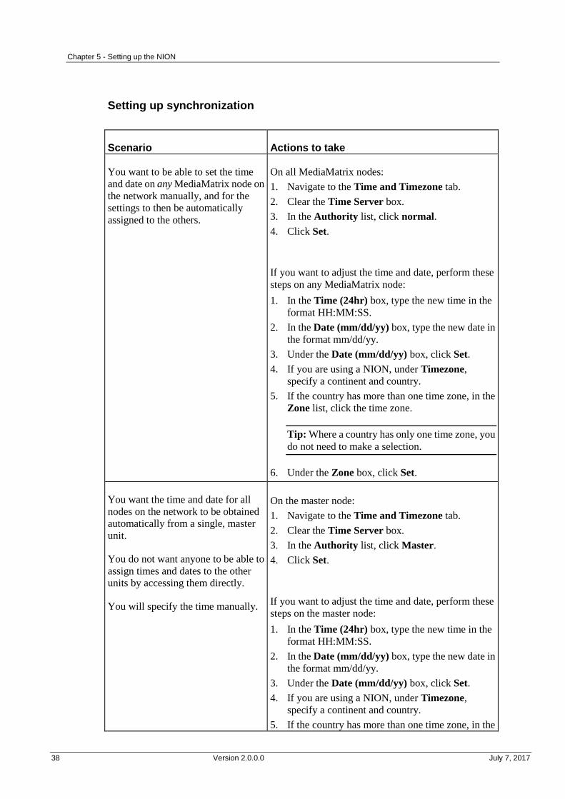
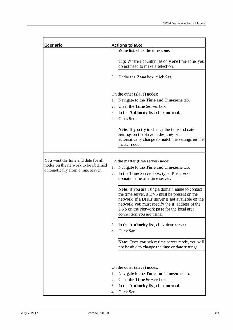
Setting up synchronization
Scenario Actions to take
You want to be able to set the time
and date on any MediaMatrix node on
the network manually, and for the
settings to then be automatically
assigned to the others.
On all MediaMatrix nodes:
1. Navigate to the Time and Timezone tab.
2. Clear the Time Server box.
3. In the Authority list, click normal.
4. Click Set.
If you want to adjust the time and date, perform these
steps on any MediaMatrix node:
1. In the Time (24hr) box, type the new time in the
format HH:MM:SS.
2. In the Date (mm/dd/yy) box, type the new date in
the format mm/dd/yy.
3. Under the Date (mm/dd/yy) box, click Set.
4. If you are using a NION, under Timezone,
specify a continent and country.
5. If the country has more than one time zone, in the
Zone list, click the time zone.
Tip: Where a country has only one time zone, you
do not need to make a selection.
6. Under the Zone box, click Set.
You want the time and date for all
nodes on the network to be obtained
automatically from a single, master
unit.
You do not want anyone to be able to
assign times and dates to the other
units by accessing them directly.
You will specify the time manually.
On the master node:
1. Navigate to the Time and Timezone tab.
2. Clear the Time Server box.
3. In the Authority list, click Master.
4. Click Set.
If you want to adjust the time and date, perform these
steps on the master node:
1. In the Time (24hr) box, type the new time in the
format HH:MM:SS.
2. In the Date (mm/dd/yy) box, type the new date in
the format mm/dd/yy.
3. Under the Date (mm/dd/yy) box, click Set.
4. If you are using a NION, under Timezone,
specify a continent and country.
5. If the country has more than one time zone, in the
NION Dante Hardware Manual
July 7, 2017 Version 2.0.0.0 39
Scenario Actions to take
Zone list, click the time zone.
Tip: Where a country has only one time zone, you
do not need to make a selection.
6. Under the Zone box, click Set.
On the other (slave) nodes:
1. Navigate to the Time and Timezone tab.
2. Clear the Time Server box.
3. In the Authority list, click normal.
4. Click Set.
Note: If you try to change the time and date
settings on the slave nodes, they will
automatically change to match the settings on the
master node.
You want the time and date for all
nodes on the network to be obtained
automatically from a time server.
a)
On the master (time server) node:
1. Navigate to the Time and Timezone tab.
2. In the Time Server box, type IP address or
domain name of a time server.
Note: If you are using a domain name to contact
the time server, a DNS must be present on the
network. If a DHCP server is not available on the
network, you must specify the IP address of the
DNS on the Network page for the local area
connection you are using.
3. In the Authority list, click time server.
4. Click Set.
Note: Once you select time server mode, you will
not be able to change the time or date settings.
On the other (slave) nodes:
1. Navigate to the Time and Timezone tab.
2. Clear the Time Server box.
3. In the Authority list, click normal.
4. Click Set.

Chapter 5 - Setting up the NION
40 Version 2.0.0.0 July 7, 2017
Scenario Actions to take
Note: If you try to change the time and date
settings on the slave nodes, they will
automatically change to match the settings on the
time server node.
Copying media files to the NION
You can copy media files over to the NION using FTP and then use them in your NWare
projects. This allows you to quickly change the available media in a project. You can also
minimize the size of the NWare project file by storing your media on the NION and not in the
project file itself. You can use any FTP client to copy the files.
In order to allow files to be copied, you need to enable the FTP server on the node you are
using. This is done via the web interface. Once FTP is enabled, you can use an FTP client (or
the FTP command from a Command Prompt window) to copy files over.
Files on an nControl unit can be played using a Media Player device in your NWare design.
Files on a NION can be played using a Wave File Player device in your NWare design.
For more information on these devices, refer to the NWare Device Reference.
Notes:
It is not currently possible to view the amount of available space for storing media files.
When the project is deployed, media files must be located on the same node that hosts the
NWare device playing the files. If the files are located on a different node, you will not be
able to play them. We recommend that you manually assign the device playing the files to
a role and deploy that role to the node that will host the media files.
You can disable the FTP server by clearing the FTP check box (see procedure below), but
if you are using an nControl unit or nTouch 180 unit, you must restart it before the change
will take effect.
To enable the FTP server
1. Navigate to the Network screen.
2. Under Services, select the FTP check box.
3. Click Set to confirm the action.
You will be asked to log on.
4. Specify your username and password. The default username is superuser; it has no
password.
To copy media files to the NION
1. Open a Command Prompt window.
2. Navigate to the folder containing the media files.
3. Type FTP and press Enter.
The ftp> prompt is displayed.
NION Dante Hardware Manual
July 7, 2017 Version 2.0.0.0 41
4. Type open <IP address of NION> and press Enter.
The following message is displayed.
Connected to <IP address>.
...
User (<IP address>:(none)):
5. Type anonymous and press Enter.
6. If you are prompted for a password, press Enter.
You do not need to specify a password.
7. If you want to list the files already copied to the unit, type ls and press Enter.
8. Type binary to switch to binary copy mode.
9. Type mput <filename> and press Enter.
The parameter <filename> is either a single file or a wildcard referencing multiple files.
When you have finished copying files, type quit to close the ftp session.
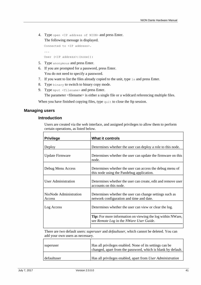
Managing users
Introduction
Users are created via the web interface, and assigned privileges to allow them to perform
certain operations, as listed below.
Privilege What it controls
Deploy Determines whether the user can deploy a role to this node.
Update Firmware Determines whether the user can update the firmware on this
node.
Debug Menu Access Determines whether the user can access the debug menu of
this node using the Pandebug application.
User Administration Determines whether the user can create, edit and remove user
accounts on this node.
NioNode Administration
Access
Determines whether the user can change settings such as
network configuration and time and date.
Log Access Determines whether the user can view or clear the log.
Tip: For more information on viewing the log within NWare,
see Remote Log in the NWare User Guide.
There are two default users: superuser and defaultuser, which cannot be deleted. You can
add your own users as necessary.
superuser Has all privileges enabled. None of its settings can be
changed, apart from the password, which is blank by default.
defaultuser Has all privileges enabled, apart from User Administration
Chapter 5 - Setting up the NION
42 Version 2.0.0.0 July 7, 2017
and NioNode Administration Access.
In NWare, when you perform an action that involves the node, such as deploying a role or
updating firmware, NWare logs on to the node using a particular username. The node matches
this username with the username of the same name stored on the unit. The privileges of the
username on the node determine whether the action may be carried out.
Tip: Users often log on to nodes with the username defaultuser. If the settings for this
username on the node show the Deploy privilege set to Disallow, it will not be possible to
deploy a role to the node even when they are logged on.
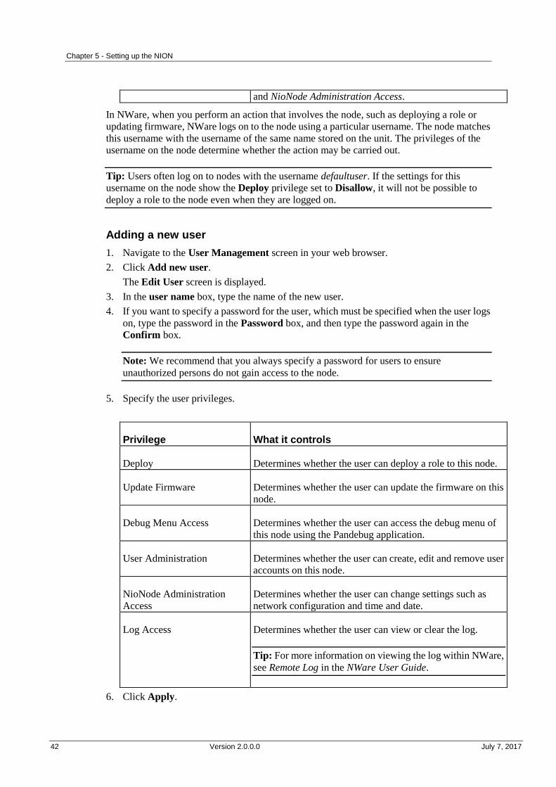
Adding a new user
1. Navigate to the User Management screen in your web browser.
2. Click Add new user.
The Edit User screen is displayed.
3. In the user name box, type the name of the new user.
4. If you want to specify a password for the user, which must be specified when the user logs
on, type the password in the Password box, and then type the password again in the
Confirm box.
Note: We recommend that you always specify a password for users to ensure
unauthorized persons do not gain access to the node.
5. Specify the user privileges.
Privilege What it controls
Deploy Determines whether the user can deploy a role to this node.
Update Firmware Determines whether the user can update the firmware on this
node.
Debug Menu Access Determines whether the user can access the debug menu of
this node using the Pandebug application.
User Administration Determines whether the user can create, edit and remove user
accounts on this node.
NioNode Administration
Access
Determines whether the user can change settings such as
network configuration and time and date.
Log Access Determines whether the user can view or clear the log.
Tip: For more information on viewing the log within NWare,
see Remote Log in the NWare User Guide.
6. Click Apply.

NION Dante Hardware Manual
July 7, 2017 Version 2.0.0.0 43
Deleting a user
You can delete users from a node when they are no longer required.
Note: You cannot delete defaultuser or superuser.
To delete a user
1. Navigate to the User Management screen in your web browser.
2. Click the Delete button next to the user you want to delete.
You will be asked to confirm the delete operation.
3. Click Yes.
Managing the role
In an NWare project, devices that are part of the design are assigned to roles, either
automatically by NWare or manually by the user. Each role is then assigned to a NION,
nControl unit or nTouch 180 unit for processing when the project is deployed.
Tip: Once a project has been deployed to a node, if the node is power cycled, the project is
restarted automatically.
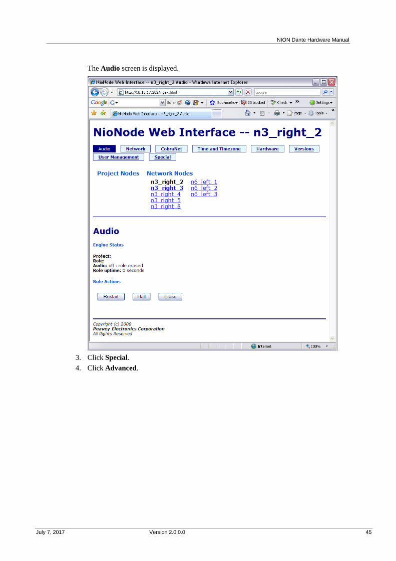
The Audio screen shows the NWare project to which the role belongs, the name of the role and
how long it has been loaded.
Restarting the role
1. On the Audio screen, under Role Actions, click Restart.
2. Click OK to confirm the action.
Stopping the role
1. On the Audio screen, under Role Actions, click Halt.
2. Click OK to confirm the action.
Erasing the role
1. On the Audio screen, under Role Actions, click Erase.
Chapter 5 - Setting up the NION
44 Version 2.0.0.0 July 7, 2017
2. Click OK to confirm the action.
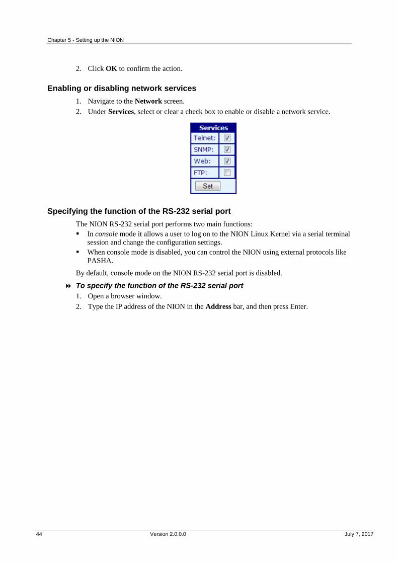
Enabling or disabling network services
1. Navigate to the Network screen.
2. Under Services, select or clear a check box to enable or disable a network service.
Specifying the function of the RS-232 serial port
The NION RS-232 serial port performs two main functions:
In console mode it allows a user to log on to the NION Linux Kernel via a serial terminal
session and change the configuration settings.
When console mode is disabled, you can control the NION using external protocols like
PASHA.
By default, console mode on the NION RS-232 serial port is disabled.
To specify the function of the RS-232 serial port
1. Open a browser window.
2. Type the IP address of the NION in the Address bar, and then press Enter.
NION Dante Hardware Manual
July 7, 2017 Version 2.0.0.0 45
The Audio screen is displayed.
3. Click Special.
4. Click Advanced.
Chapter 5 - Setting up the NION
46 Version 2.0.0.0 July 7, 2017
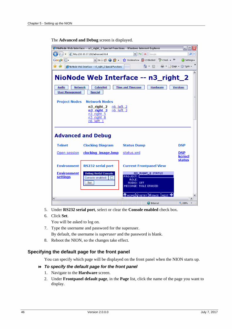
The Advanced and Debug screen is displayed.
5. Under RS232 serial port, select or clear the Console enabled check box.
6. Click Set.
You will be asked to log on.
7. Type the username and password for the superuser.
By default, the username is superuser and the password is blank.
8. Reboot the NION, so the changes take effect.
Specifying the default page for the front panel
You can specify which page will be displayed on the front panel when the NION starts up.
To specify the default page for the front panel
1. Navigate to the Hardware screen.
2. Under Frontpanel default page, in the Page list, click the name of the page you want to
display.

NION Dante Hardware Manual
July 7, 2017 Version 2.0.0.0 47
Updating the firmware
Firmware on NIONs is managed centrally using NWare. For information on updating
firmware, see Updating firmware on MediaMatrix devices in the NWare User Guide.
Using XDAB to share DSP resources
Clusters of NIONs can be interconnected in an XDAB ring, allowing up to 512 channels of
redundant, low-latency audio to be exchanged. Wiring devices together in this way allows
available DSP processing capacity to be shared between the group.
Note: The maximum channel count scales proportionally to the chosen sample rate. At a
48KHz sampling rate, 448 channels of audio can be exchanged.
Each NION has two XDAB ports, marked IN and OUT, which are used to physically wire
them together in a ring using shielded CAT-6 cabling. The order of the NIONs in the ring is
not important, since it is determined, and adjusted for, when the associated NWare project is
deployed. However, NIONs that are specified as members of the same XDAB ring must be
physically connected, otherwise each unit will indicate that a fault has occurred.
For information on XDAB performance, see XDAB performance (NION n3, NION n6) (on
page 71). For information on using XDAB with VLANs, see Using XDAB clusters with
VLANs and Dante in the Dante Networking Guide.
To connect the NIONs together
Use CAT 6 cables to connect the NIONs together using the XDAB IN and OUT ports at
the rear.
We recommend you use a configuration like the one shown below. This will give optimum
performance and reliability.

Chapter 5 - Setting up the NION
48 Version 2.0.0.0 July 7, 2017
What to do next
NIONs are designed to be used in conjunction with an NWare project. Refer to the section
Adding a NioNode to your design in the NWare User Guide for more information.

July 7, 2017 Version 2.0.0.0 49
In This Appendix
Cannot access NION using IP address or IP address is unknown .................... 50
Front panel LED indicators ............................................................................... 52
Including debug messages in the log ................................................................ 53
Low voltage warning ........................................................................................ 54
NION locking up or rebooting spuriously ........................................................ 54
Append ix A
Troubleshooting

Appendix A - Troubleshooting
50 Version 2.0.0.0 July 7, 2017
.
Cannot access NION using IP address or IP address is unknown
There are two main solutions to this problem:
Use NDP to discover the NION on the network and assign an IP address (see Using NDP
to discover network devices and assign network settings in the NWare User Guide).
Use a serial cable to connect directly to the NION and assign and IP address (on page 50).
Using a direct serial connection to assign an IP address
This section explains how to connect to a NION directly via the serial port and change the IP
address settings. This is only necessary under the following circumstances:
The NION does not appear on the Remote Log tab in NWare and Pandad is functioning
(i.e. other NIONs on the same network are listed). If you need to check to see if Pandad has
stopped working, see Determining if Pandad has stopped functioning.
The NION is listed on the Remote Log tab, but when you right-click it and then click
Launch Web Interface, the web interface is not displayed.
You need to access a NION using its IP address, but the address is unknown and you are
unable to run NWare to discover all the NIONs on the network.
Caution: It is very important that you only complete the steps in this section when under
instruction from MediaMatrix Technical Support. It is possible to lose data stored on the
NION or to stop it from booting if you specify settings incorrectly.
Note: The first procedure below assumes that the key used to stop the NION boot sequence is
ESC, which is the default setting. This is specified by the bootstopkey environment variable. If
you do not know the appropriate key and are unable to stop the boot sequence, contact
MediaMatrix Technical Support.
Tips:
If the NION is fitted with a front panel, you can change the IP address using the front panel
interface. For more information, see Setting the IP address.
If the NION has been assigned correct IP settings, but you are still unable to start the web
interface, this may be because the IP address of your PC is not compatible with the IP
address of the NION. Consider changing the IP address of your PC so that it can
communicate with the NION. The format of the NION IP address will be shown in the
URL used when attempting to start the web interface.
To connect to the NION via the serial port
1. Connect a serial cable between the PC serial port and the serial port on the MediaMatrix
node.
2. Start a terminal emulator program, then specify connection settings to match those already
specified on the MediaMatrix node. For example:
baud rate 57600
NION Dante Hardware Manual
July 7, 2017 Version 2.0.0.0 51
8 bit data
no parity
1 stop bit
no flow control.
3. Power cycle the NION.
4. As soon as the NION starts to boot up (and the fans can be heard), continuously press the
ESC key.
A command prompt like this => will be displayed in the console window.
5. Press Enter.
To specify a static IP address
1. Type setenv dhcp no and press Enter.
2. Type setenv ipaddr <IP address> and press Enter.
3. Type setenv netmask <subnet mask> and press Enter.
4. If you want the settings to be saved and used each time the NION boots, type saveenv and
press Enter.
If you omit this step, the settings will only be used for the current session.
5. Type boot and press Enter.
To specify an IP address automatically using DHCP
1. Type setenv dhcp yes and press Enter.
2. If you want the settings to be saved and used each time the NION boots, type saveenv and
press Enter.
If you omit this step, the settings will only be used for the current session.
3. Type boot and press Enter.
Some examples
Scenario Command to use
The NION is configured with a static IP
address, but you want to assign a new
address that is temporary.
setenv ipaddr 10.1.10.100
setenv netmask 255.255.0.0
boot
You want to use DHCP for this session and
each time the NION boots.
setenv dhcp yes
saveenv
boot
You want to use a static IP address for this
session and each time the NION boots.
setenv dhcp no
setenv ipaddr 10.1.10.100
setenv netmask 255.255.0.0
saveenv
boot

Appendix A - Troubleshooting
52 Version 2.0.0.0 July 7, 2017
Front panel LED indicators
There are several LEDs on the NION front panel that help indicate unit status.
Fault
RED Audio not working.
OFF Audio working.
The Fault LED tracks the state of the fault relay. (The fault relay signals appear on pins of the
GPIO connector.)
Note: The RED state does not necessarily indicate a problem, but that audio is not actively
being processed and passed. This state occurs normally when the unit is rebooting or has not
yet been configured to run a Project. It also occurs when the unit has encountered a problem
and can no longer process and pass audio.
X-DAB
GREEN Primary and backup rings are operational.
YELLOW OR
GREEN
BLINKING
Running in backup with single cable missing - all audio present.
YELLOW/RED
OR RED
BLINKING
Running in backup mode with multiple cables/nodes missing - some
audio gone.
RED Failure - some or all audio gone. Not running in backup mode.
OFF XDAB is not in use (in the current Project/Role for this NioNode).
Note: The XDAB LED is updated only when XDAB is used by the NioNode in the current
Project and the NioNode is up and passing audio.
LAN
GREEN Ethernet link.
OFF No Ethernet Link.
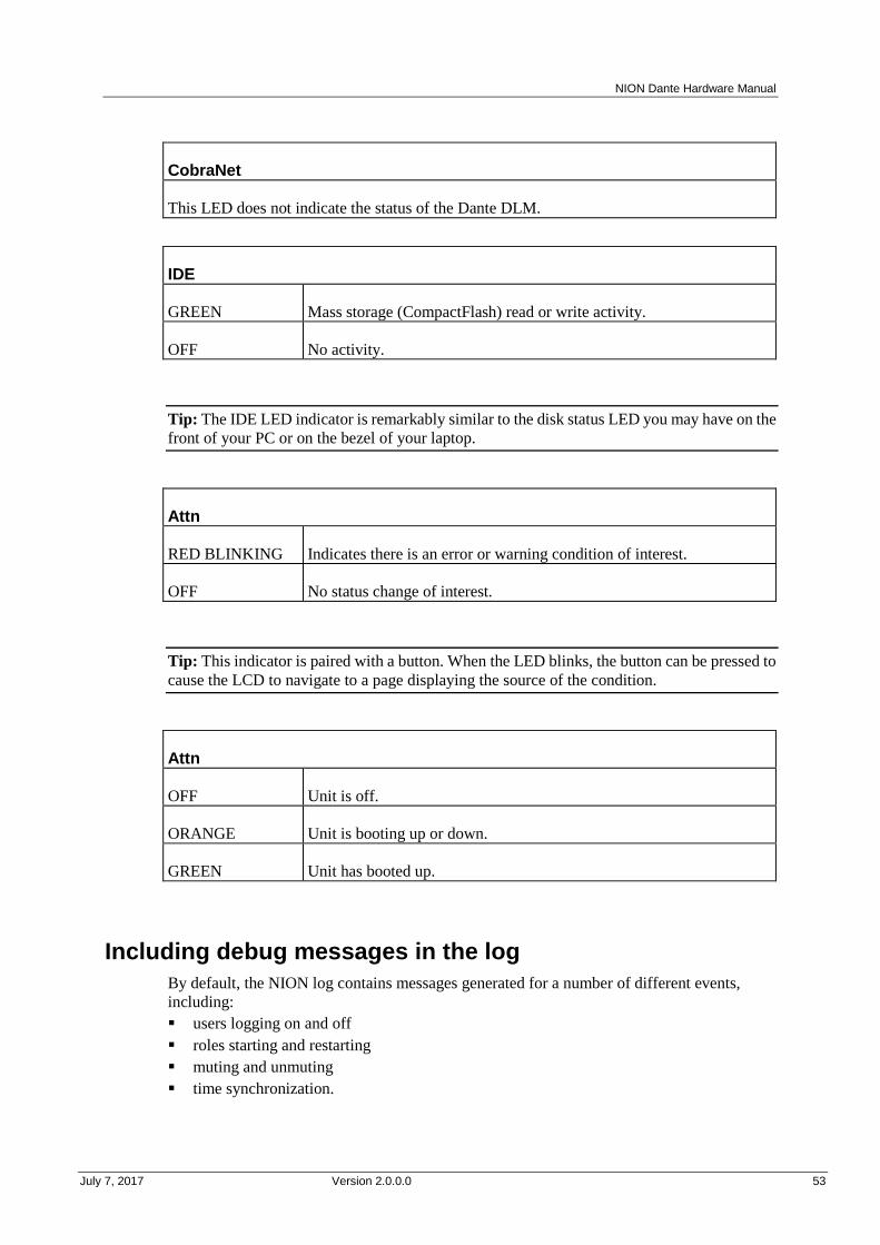
NION Dante Hardware Manual
July 7, 2017 Version 2.0.0.0 53
CobraNet
This LED does not indicate the status of the Dante DLM.
IDE
GREEN Mass storage (CompactFlash) read or write activity.
OFF No activity.
Tip: The IDE LED indicator is remarkably similar to the disk status LED you may have on the
front of your PC or on the bezel of your laptop.
Attn
RED BLINKING Indicates there is an error or warning condition of interest.
OFF No status change of interest.
Tip: This indicator is paired with a button. When the LED blinks, the button can be pressed to
cause the LCD to navigate to a page displaying the source of the condition.
Attn
OFF Unit is off.
ORANGE Unit is booting up or down.
GREEN Unit has booted up.
Including debug messages in the log
By default, the NION log contains messages generated for a number of different events,
including:
users logging on and off
roles starting and restarting
muting and unmuting
time synchronization.

Appendix A - Troubleshooting
54 Version 2.0.0.0 July 7, 2017
If you are troubleshooting a problem on a NioNode and you want to view debug messages in
the log (and not just the default messages), you must enable the logging of each type of
message using the web interface.
Tip: Entries are added to the log until 2MB of storage has been used (and approximately
22,000 lines have been stored). 1MB of the oldest log data is then deleted automatically,
making room available for new entries. The available space is the same, regardless of the
amount of compact flash memory fitted to the NION.
To include debug messages in the log
1. In NWare, click the Remote Log tab at the bottom window.
2. In the Targets Found pane, right-click on the NioNode and then click Launch Web
Interface.
A browser will be opened displaying the home page of the selected NioNode.
3. In the browser, click Special at the top of the page.
4. At the bottom of page, Click advanced.
5. Under Debug Logging, select check boxes next to the types of debug messages you want
to include in the NION log.
If you want to include all types of debug messages, scroll to the bottom of the window, and
then click set all.
6. Click apply.
7. Specify your username and password. The default username is superuser; it has no
password.
Low voltage warning
When using phantom power for high current draw condenser mics on NIONs, and when all
four I/O slots are populated with ML II cards, the +/-24V power voltage may drop a little. This
is because on some NIONs, the 24V power supply current limit is slightly low. This voltage
drop is sometimes sufficient to trigger the voltage warning: the Attn button on the front of the
NION will flash red, and pressing it will bring up the voltage monitoring screen, with the
+/-24V measurements highlighted.
Under most conditions, the voltage drop will not have any effect on the functioning of the
NION, because the full 24V is actually substantially more than the cards require. The 24V
supplies feed local regulators on the cards which generate a substantially lower voltage for the
analogue i/o circuits - this decouples the analogue circuitry from variations in the 24V supply.
The problem can be worked around by using less power hungry microphones or by removing
one of the ML II cards from the unit. If you cannot do this, contact your local NION service
agent.
NION locking up or rebooting spuriously
If you load a role onto a NION and find that the unit has locked up, or keeps rebooting
spuriously, it may not be possible to erase the role via the front panel or the web interface using
the normal methods.
The NION includes a service menu, accessible at boot time, which will allow you to boot the
unit, but not load the role. It can then be erased.

NION Dante Hardware Manual
July 7, 2017 Version 2.0.0.0 55
Caution: It is very important that you follow the instructions in this section carefully. Do not
experiment with other options in the service menu. You could make the NION inoperable.
To stop the role from loading automatically at boot time
1. Switch off the NION by pressing the Power button, and then selecting OK.
2. Hold down the two buttons indicated below.
3. While holding down the buttons, press the Power button to switch the NION back on.
This menu will be displayed.
OPTIONS:
> WHEEL TO EDIT
> ATTN TO BOOT
UPDATE MEDIA
4. Turn the wheel clockwise until BOOT MODE is displayed.
5. Push the wheel button.
6. Turn the wheel to select QUIET, then push the wheel button to select the option.
7. Press Attn.
The NION will boot. You will then be able to erase the role without running it.
8. Reboot the NION.
The NION will start in NORMAL boot mode.

July 7, 2017 Version 2.0.0.0 57
In This Appendix
GPIO overview ................................................................................................. 58
Serial communications ...................................................................................... 62
Append ix B
Connector ports
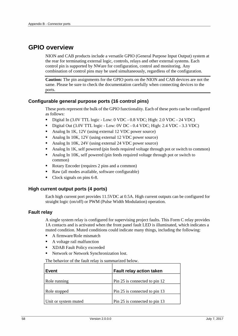
Appendix B - Connector ports
58 Version 2.0.0.0 July 7, 2017
.
GPIO overview
NION and CAB products include a versatile GPIO (General Purpose Input Output) system at
the rear for terminating external logic, controls, relays and other external systems. Each
control pin is supported by NWare for configuration, control and monitoring. Any
combination of control pins may be used simultaneously, regardless of the configuration.
Caution: The pin assignments for the GPIO ports on the NION and CAB devices are not the
same. Please be sure to check the documentation carefully when connecting devices to the
ports.
Configurable general purpose ports (16 control pins)
These ports represent the bulk of the GPIO functionality. Each of these ports can be configured
as follows:
Digital In (3.0V TTL logic - Low: 0 VDC - 0.8 VDC; High: 2.0 VDC - 24 VDC)
Digital Out (3.0V TTL logic - Low: 0V DC - 0.4 VDC; High: 2.4 VDC - 3.3 VDC)
Analog In 1K, 12V (using external 12 VDC power source)
Analog In 10K, 12V (using external 12 VDC power source)
Analog In 10K, 24V (using external 24 VDC power source)
Analog In 1K, self powered (pin feeds required voltage through pot or switch to common)
Analog In 10K, self powered (pin feeds required voltage through pot or switch to
common)
Rotary Encoder (requires 2 pins and a common)
Raw (all modes available, software configurable)
Clock signals on pins 6-8.
High current output ports (4 ports)
Each high current port provides 11.5VDC at 0.5A. High current outputs can be configured for
straight logic (on/off) or PWM (Pulse Width Modulation) operation.
Fault relay
A single system relay is configured for supervising project faults. This Form C relay provides
1A contacts and is activated when the front panel fault LED is illuminated, which indicates a
muted condition. Muted conditions could indicate many things, including the following:
A firmware/Role mismatch
A voltage rail malfunction
XDAB Fault Policy exceeded
Network or Network Synchronization lost.
The behavior of the fault relay is summarized below.
Event Fault relay action taken
Role running Pin 25 is connected to pin 12
Role stopped Pin 25 is connected to pin 13
Unit or system muted Pin 25 is connected to pin 13
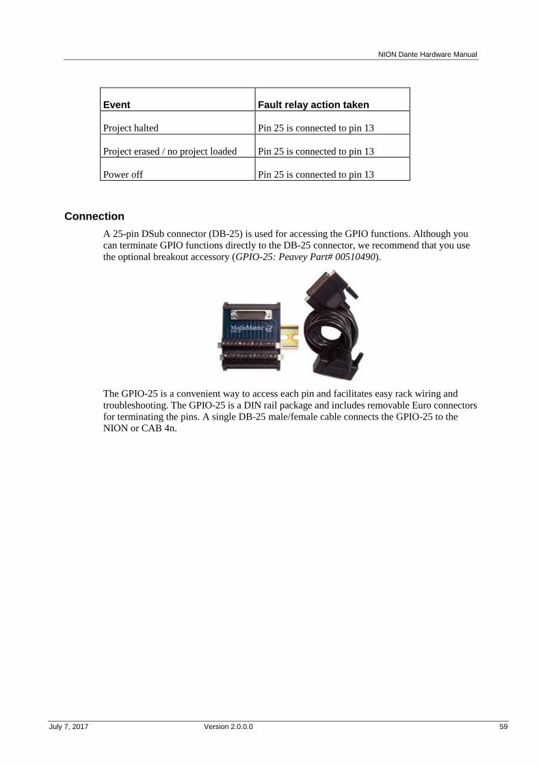
NION Dante Hardware Manual
July 7, 2017 Version 2.0.0.0 59
Event Fault relay action taken
Project halted Pin 25 is connected to pin 13
Project erased / no project loaded Pin 25 is connected to pin 13
Power off Pin 25 is connected to pin 13
Connection
A 25-pin DSub connector (DB-25) is used for accessing the GPIO functions. Although you
can terminate GPIO functions directly to the DB-25 connector, we recommend that you use
the optional breakout accessory (GPIO-25: Peavey Part# 00510490).
The GPIO-25 is a convenient way to access each pin and facilitates easy rack wiring and
troubleshooting. The GPIO-25 is a DIN rail package and includes removable Euro connectors
for terminating the pins. A single DB-25 male/female cable connects the GPIO-25 to the
NION or CAB 4n.
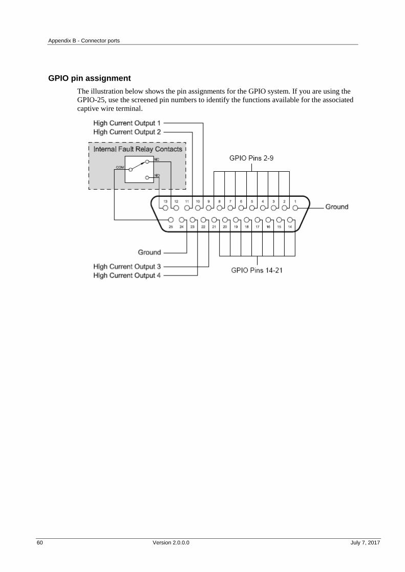
Appendix B - Connector ports
60 Version 2.0.0.0 July 7, 2017
GPIO pin assignment
The illustration below shows the pin assignments for the GPIO system. If you are using the
GPIO-25, use the screened pin numbers to identify the functions available for the associated
captive wire terminal.
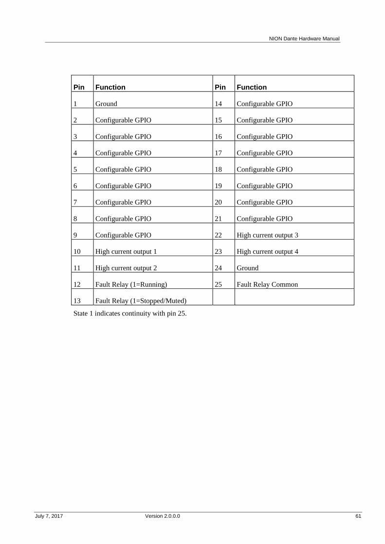
NION Dante Hardware Manual
July 7, 2017 Version 2.0.0.0 61
.
Pin Function Pin Function
1 Ground 14 Configurable GPIO
2 Configurable GPIO 15 Configurable GPIO
3 Configurable GPIO 16 Configurable GPIO
4 Configurable GPIO 17 Configurable GPIO
5 Configurable GPIO 18 Configurable GPIO
6 Configurable GPIO 19 Configurable GPIO
7 Configurable GPIO 20 Configurable GPIO
8 Configurable GPIO 21 Configurable GPIO
9 Configurable GPIO 22 High current output 3
10 High current output 1 23 High current output 4
11 High current output 2 24 Ground
12 Fault Relay (1=Running) 25 Fault Relay Common
13 Fault Relay (1=Stopped/Muted)
State 1 indicates continuity with pin 25.
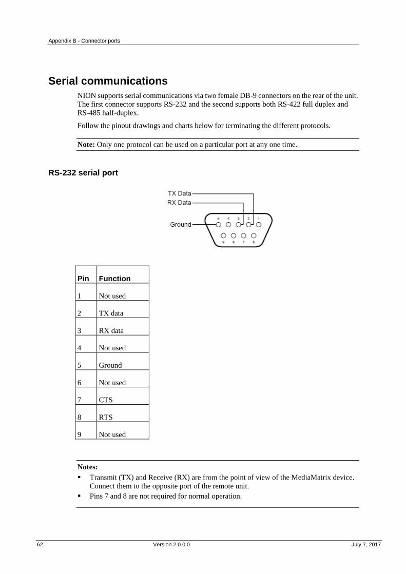
Appendix B - Connector ports
62 Version 2.0.0.0 July 7, 2017
.
Serial communications
NION supports serial communications via two female DB-9 connectors on the rear of the unit.
The first connector supports RS-232 and the second supports both RS-422 full duplex and
RS-485 half-duplex.
Follow the pinout drawings and charts below for terminating the different protocols.
Note: Only one protocol can be used on a particular port at any one time.
RS-232 serial port
Pin Function
1 Not used
2 TX data
3 RX data
4 Not used
5 Ground
6 Not used
7 CTS
8 RTS
9 Not used
Notes:
Transmit (TX) and Receive (RX) are from the point of view of the MediaMatrix device.
Connect them to the opposite port of the remote unit.
Pins 7 and 8 are not required for normal operation.
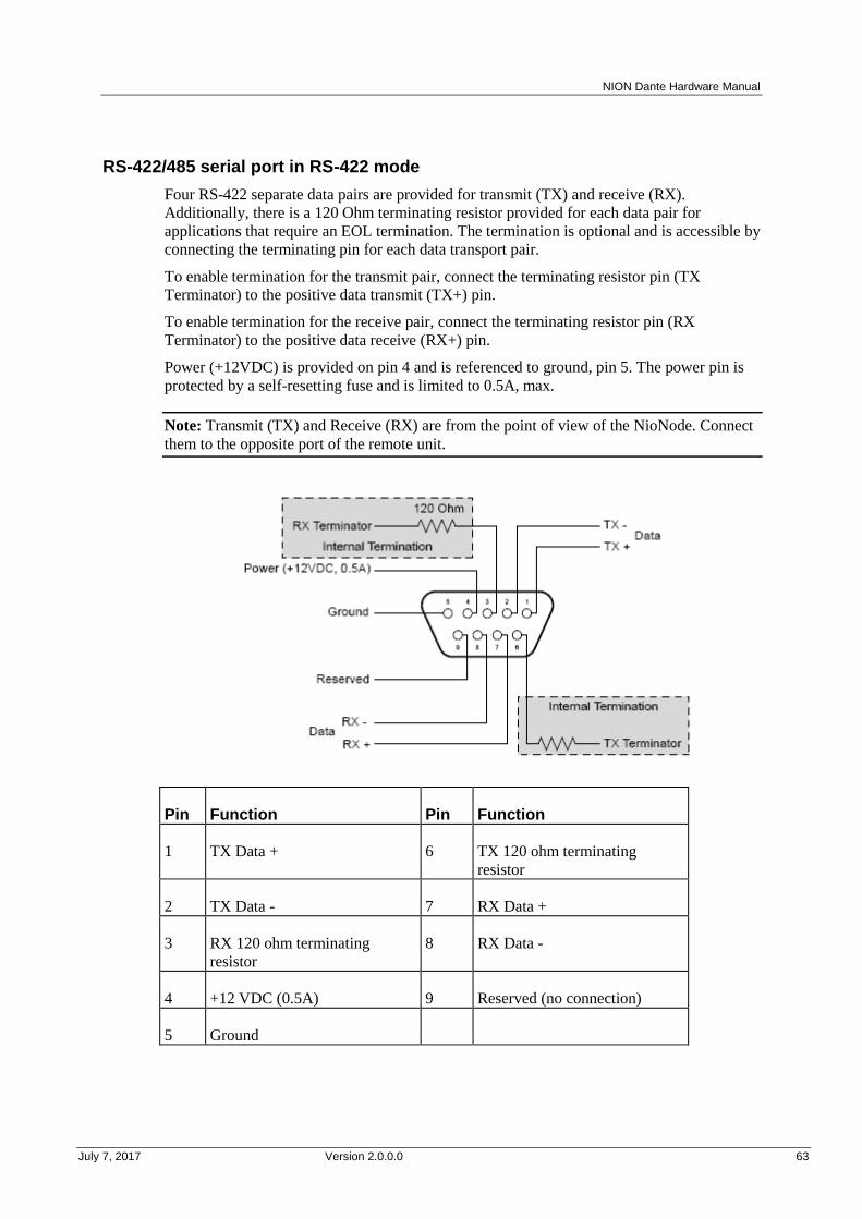
NION Dante Hardware Manual
July 7, 2017 Version 2.0.0.0 63
RS-422/485 serial port in RS-422 mode
Four RS-422 separate data pairs are provided for transmit (TX) and receive (RX).
Additionally, there is a 120 Ohm terminating resistor provided for each data pair for
applications that require an EOL termination. The termination is optional and is accessible by
connecting the terminating pin for each data transport pair.
To enable termination for the transmit pair, connect the terminating resistor pin (TX
Terminator) to the positive data transmit (TX+) pin.
To enable termination for the receive pair, connect the terminating resistor pin (RX
Terminator) to the positive data receive (RX+) pin.
Power (+12VDC) is provided on pin 4 and is referenced to ground, pin 5. The power pin is
protected by a self-resetting fuse and is limited to 0.5A, max.
Note: Transmit (TX) and Receive (RX) are from the point of view of the NioNode. Connect
them to the opposite port of the remote unit.
Pin Function Pin Function
1 TX Data + 6 TX 120 ohm terminating
resistor
2 TX Data - 7 RX Data +
3 RX 120 ohm terminating
resistor
8 RX Data -
4 +12 VDC (0.5A) 9 Reserved (no connection)
5 Ground

Appendix B - Connector ports
64 Version 2.0.0.0 July 7, 2017
RS-422/485 serial port in RS-485 mode
For RS-485 applications the serial port is configured for half-duplex operation. A single data
pair is provided for transmit (Data+) and receive (Data-).
Additionally, there is a 120 Ohm terminating resistor provided for applications that require an
EOL termination. The termination is optional and is accessible by connecting the terminating
pin (TX Terminator) to the positive data (Data+) pin.
Power (+12VDC) is provided on pin 4 and is referenced to ground, pin 5. The power pin is
protected by a self-resetting fuse and is limited to 0.5A, max.
Pin Function Pin Function
1 Data + 6 TX 120 ohm terminating resistor
2 Data - 7 Not used
3 Not used 8 Not used
4 +12 VDC (0.5A) 9 Reserved (no connection)
5 Ground

NION Dante Hardware Manual
July 7, 2017 Version 2.0.0.0 65
.
Serial control protocols
You may use any of the following protocols with the NION serial ports.
None/Comms processor Used when the project contains a Comms Processor device,
or when you do not want to use the serial port.
Note: If you select one of the other options – RATC2, for
example, then try to use the Comms Processor device, it
will not respond as quickly.
RATC2 RATC2 is the improved version of RATC that was
introduced with the NION platform, but is also supported
by nControl and nTouch 180. Very similar to RATC1,
RATC2 introduces shortened commands, and several extra
functions.
RATC1 RATC1 is the first generation protocol that was used in
Classic frame-based MediaMatrix systems. RATC1 for
NioNodes, nTouch 180 nodes and nControl nodes is
equivalent to what was called RATC in Classic
MediaMatrix.
PASHA/PageMatrix Protocol used with the PageMatrix Command Center. It
supports a four character control ID sent with the (T)
trigger command.
PASHA/XControl Provides basic S (Set) PASHA functionality with
X-Net2-style trigger commands.
PASHA/Legacy Designed for projects that contain legacy MediaMatrix
nodes that are controlled by external programs using the
classic PASHA protocol, as implemented on MainFrames
and MiniFrames. When you want to replace the legacy
nodes with NioNodes, select the PASHA/Legacy option and
you will not need to update your external program code.
This option ensures all hex values are returned from nodes
in lower case instead of upper case to match the original
MediaMatrix PASHA protocol.


July 7, 2017 Version 2.0.0.0 67
In This Appendix
Rear panel connections ..................................................................................... 68
Digital audio performance ................................................................................ 69
AES card DIP switches ..................................................................................... 70
XDAB performance (NION n3, NION n6) ...................................................... 71
Dante performance ............................................................................................ 72
GPIO ................................................................................................................. 72
Mechanical specifications ................................................................................. 72
Append ix C
Technical specifications
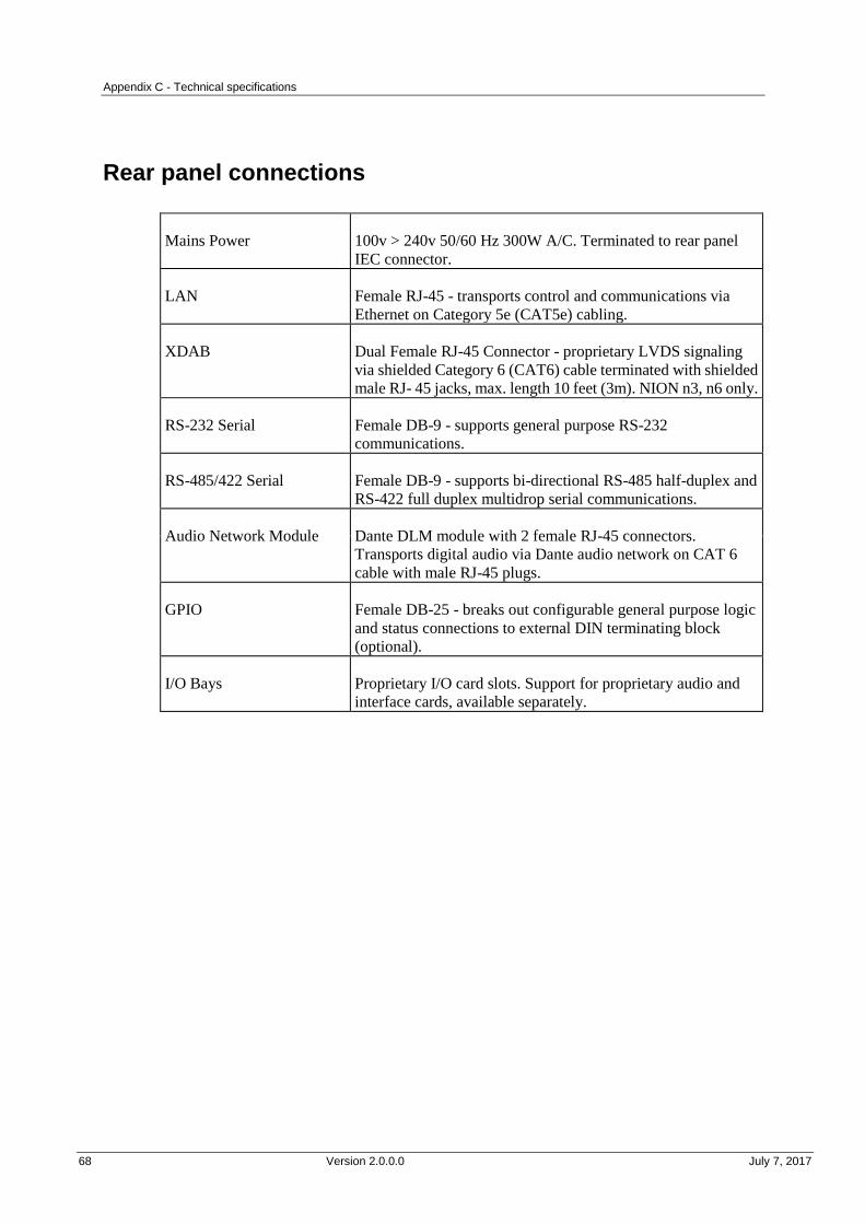
Appendix C - Technical specifications
68 Version 2.0.0.0 July 7, 2017
.
Rear panel connections
Mains Power 100v > 240v 50/60 Hz 300W A/C. Terminated to rear panel
IEC connector.
LAN Female RJ-45 - transports control and communications via
Ethernet on Category 5e (CAT5e) cabling.
XDAB Dual Female RJ-45 Connector - proprietary LVDS signaling
via shielded Category 6 (CAT6) cable terminated with shielded
male RJ- 45 jacks, max. length 10 feet (3m). NION n3, n6 only.
RS-232 Serial Female DB-9 - supports general purpose RS-232
communications.
RS-485/422 Serial Female DB-9 - supports bi-directional RS-485 half-duplex and
RS-422 full duplex multidrop serial communications.
Audio Network Module Dante DLM module with 2 female RJ-45 connectors.
Transports digital audio via Dante audio network on CAT 6
cable with male RJ-45 plugs.
GPIO Female DB-25 - breaks out configurable general purpose logic
and status connections to external DIN terminating block
(optional).
I/O Bays Proprietary I/O card slots. Support for proprietary audio and
interface cards, available separately.
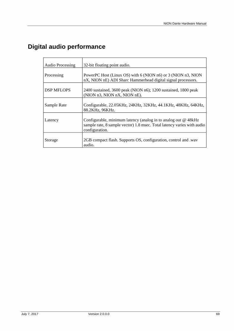
NION Dante Hardware Manual
July 7, 2017 Version 2.0.0.0 69
.
Digital audio performance
Audio Processing 32-bit floating point audio.
Processing PowerPC Host (Linux OS) with 6 (NION n6) or 3 (NION n3, NION
nX, NION nE) ADI Sharc Hammerhead digital signal processors.
DSP MFLOPS 2400 sustained, 3600 peak (NION n6); 1200 sustained, 1800 peak
(NION n3, NION nX, NION nE).
Sample Rate Configurable, 22.05KHz, 24KHz, 32KHz, 44.1KHz, 48KHz, 64KHz,
88.2KHz, 96KHz.
Latency Configurable, minimum latency (analog in to analog out @ 48kHz
sample rate, 8 sample vector) 1.8 msec. Total latency varies with audio
configuration.
Storage 2GB compact flash. Supports OS, configuration, control and .wav
audio.

Appendix C - Technical specifications
70 Version 2.0.0.0 July 7, 2017
AES card DIP switches
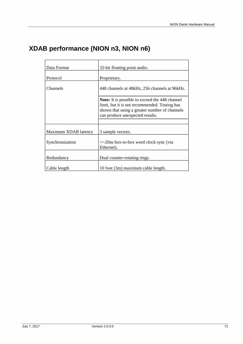
NION Dante Hardware Manual
July 7, 2017 Version 2.0.0.0 71
.
XDAB performance (NION n3, NION n6)
Data Format 32-bit floating point audio.
Protocol Proprietary.
Channels 448 channels at 48kHz, 256 channels at 96kHz.
Note: It is possible to exceed the 448 channel
limit, but it is not recommended. Testing has
shown that using a greater number of channels
can produce unexpected results.
Maximum XDAB latency 3 sample vectors.
Synchronization +/-20ns box-to-box word clock sync (via
Ethernet).
Redundancy Dual counter-rotating rings.
Cable length 10 foot (3m) maximum cable length.
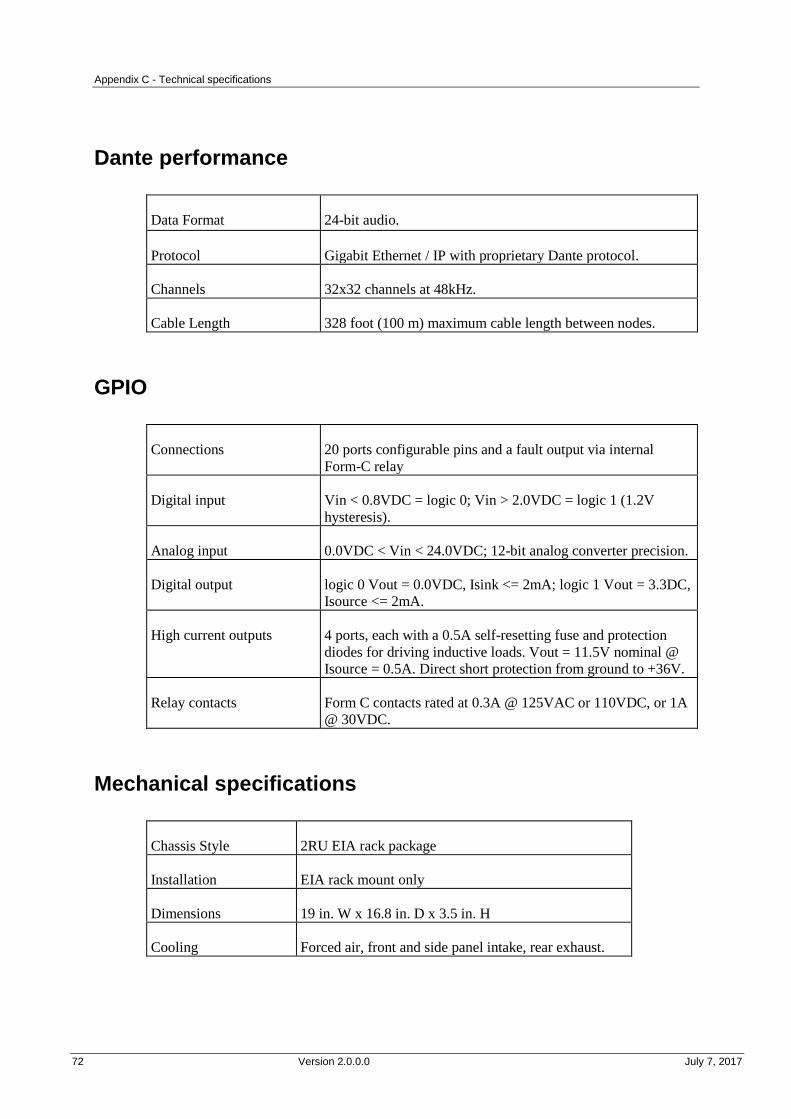
Appendix C - Technical specifications
72 Version 2.0.0.0 July 7, 2017
.
Dante performance
Data Format 24-bit audio.
Protocol Gigabit Ethernet / IP with proprietary Dante protocol.
Channels 32x32 channels at 48kHz.
Cable Length 328 foot (100 m) maximum cable length between nodes.
GPIO
Connections 20 ports configurable pins and a fault output via internal
Form-C relay
Digital input Vin < 0.8VDC = logic 0; Vin > 2.0VDC = logic 1 (1.2V
hysteresis).
Analog input 0.0VDC < Vin < 24.0VDC; 12-bit analog converter precision.
Digital output logic 0 Vout = 0.0VDC, Isink <= 2mA; logic 1 Vout = 3.3DC,
Isource <= 2mA.
High current outputs 4 ports, each with a 0.5A self-resetting fuse and protection
diodes for driving inductive loads. Vout = 11.5V nominal @
Isource = 0.5A. Direct short protection from ground to +36V.
Relay contacts Form C contacts rated at 0.3A @ 125VAC or 110VDC, or 1A
@ 30VDC.
Mechanical specifications
Chassis Style 2RU EIA rack package
Installation EIA rack mount only
Dimensions 19 in. W x 16.8 in. D x 3.5 in. H
Cooling Forced air, front and side panel intake, rear exhaust.

July 7, 2017 Version 2.0.0.0 73
In This Appendix
Architect's and engineer's specifications ........................................................... 74
Technical Support ............................................................................................. 75
Append ix D
Reference Information
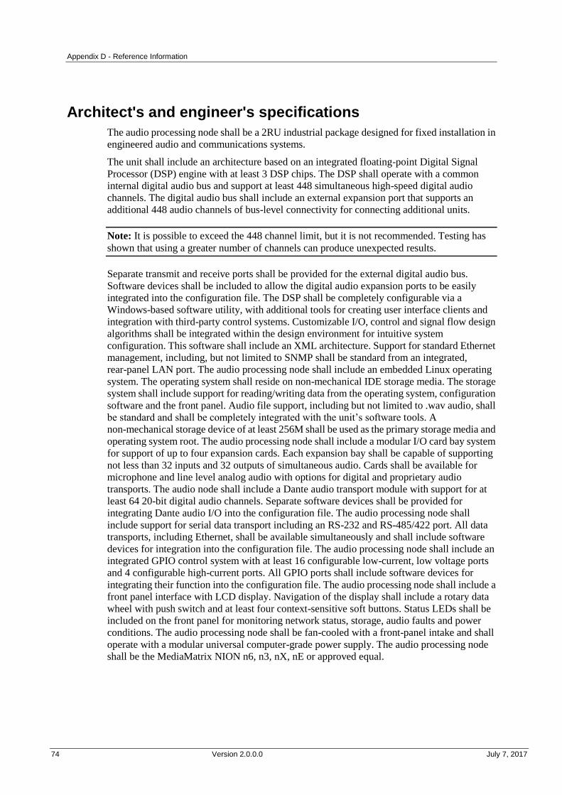
Appendix D - Reference Information
74 Version 2.0.0.0 July 7, 2017
.
Architect's and engineer's specifications
The audio processing node shall be a 2RU industrial package designed for fixed installation in
engineered audio and communications systems.
The unit shall include an architecture based on an integrated floating-point Digital Signal
Processor (DSP) engine with at least 3 DSP chips. The DSP shall operate with a common
internal digital audio bus and support at least 448 simultaneous high-speed digital audio
channels. The digital audio bus shall include an external expansion port that supports an
additional 448 audio channels of bus-level connectivity for connecting additional units.
Note: It is possible to exceed the 448 channel limit, but it is not recommended. Testing has
shown that using a greater number of channels can produce unexpected results.
Separate transmit and receive ports shall be provided for the external digital audio bus.
Software devices shall be included to allow the digital audio expansion ports to be easily
integrated into the configuration file. The DSP shall be completely configurable via a
Windows-based software utility, with additional tools for creating user interface clients and
integration with third-party control systems. Customizable I/O, control and signal flow design
algorithms shall be integrated within the design environment for intuitive system
configuration. This software shall include an XML architecture. Support for standard Ethernet
management, including, but not limited to SNMP shall be standard from an integrated,
rear-panel LAN port. The audio processing node shall include an embedded Linux operating
system. The operating system shall reside on non-mechanical IDE storage media. The storage
system shall include support for reading/writing data from the operating system, configuration
software and the front panel. Audio file support, including but not limited to .wav audio, shall
be standard and shall be completely integrated with the unit’s software tools. A
non-mechanical storage device of at least 256M shall be used as the primary storage media and
operating system root. The audio processing node shall include a modular I/O card bay system
for support of up to four expansion cards. Each expansion bay shall be capable of supporting
not less than 32 inputs and 32 outputs of simultaneous audio. Cards shall be available for
microphone and line level analog audio with options for digital and proprietary audio
transports. The audio node shall include a Dante audio transport module with support for at
least 64 20-bit digital audio channels. Separate software devices shall be provided for
integrating Dante audio I/O into the configuration file. The audio processing node shall
include support for serial data transport including an RS-232 and RS-485/422 port. All data
transports, including Ethernet, shall be available simultaneously and shall include software
devices for integration into the configuration file. The audio processing node shall include an
integrated GPIO control system with at least 16 configurable low-current, low voltage ports
and 4 configurable high-current ports. All GPIO ports shall include software devices for
integrating their function into the configuration file. The audio processing node shall include a
front panel interface with LCD display. Navigation of the display shall include a rotary data
wheel with push switch and at least four context-sensitive soft buttons. Status LEDs shall be
included on the front panel for monitoring network status, storage, audio faults and power
conditions. The audio processing node shall be fan-cooled with a front-panel intake and shall
operate with a modular universal computer-grade power supply. The audio processing node
shall be the MediaMatrix NION n6, n3, nX, nE or approved equal.
NION Dante Hardware Manual
July 7, 2017 Version 2.0.0.0 75
Technical Support
When you require assistance with your product, you can get help from several sources. Apart
from the online Knowledge Center, there are many technical documents, white papers and
application notes on our website and on other websites on the Internet, covering subjects
including Python programming, SNMP and serial control.
If you cannot find the information you require, contact your dealer or distributor. If you are
still unable to solve the issue, you can contact us directly using the details below. MediaMatrix
has an extensive Technical Services Group that provides technical support, repair and
implementation services.
Peavey Electronics Corp.,
MediaMatrix Division,
5022 Hartley Peavey Drive,
Meridian, MS 39305, USA.
Phone: 601.483.9548
Phone (toll free): 866.662.8750
Fax: 601.486.1678
Website: http://mm.peavey.com (http://www.peaveycommercialaudio.com/).


July 7, 2017 Version 2.0.0.0 77
MediaMatrix® PEAVEY ELECTRONICS CORPORATION DOMESTIC (USA) LIMITED WARRANTY Effective Date: May 1, 2005
What This Warranty Covers
This Warranty covers defects in material and workmanship in
Peavey MediaMatrix products purchased and serviced in the United
States of America (USA).
What This Warranty Does Not Cover
The Warranty does not cover: (1) damage caused by accident,
misuse, abuse, improper installation or operation, rental, product modification or neglect; (2) damage occurring during shipment; (3)
damage caused by repair or service performed by persons not
authorized by Peavey; (4) products on which the serial number has been altered, defaced or removed; (5) products not purchased from
an Authorized MediaMatrix Integrator. This warranty does not
cover associated costs incurred from servicing equipment, including, but not limited to, travel, jobsite-related costs,
fabrication, freight, loaner equipment, installation, cabling or
harnessing, mounting materials or other variable costs.
Who This Warranty Protects
In applications where the product is sold over the counter, this
Warranty protects the original retail purchaser. In applications
where the product is part of an integrated system, and such system is warrantied by the integrator as a complete assembly, this Warranty
protects only the system integrator.
What Peavey Will Do
We will repair or replace (at Peavey's discretion) products covered
by warranty at no charge for labor or materials. If the product or
component must be shipped to Peavey for warranty service, the
consumer must pay initial shipping costs. If the repairs are covered by warranty, Peavey will pay the return shipping costs.
How Long This Warranty Lasts
The Warranty begins on the date of purchase by the original retail
purchaser or on the date received by the system integrator. (See Who This Warranty Protects, above). The duration of the Warranty
varies by product as summarized below.
5 Years MediaMatrix® DPU cards, NION™ Processing
Nodes, CABs, I/O cards, Cinema Processors, Power Amplifiers, Pre-Amplifiers, Mixers, Electronic Filter
Sets and Dynamics Processors.
1 Year MM Series Cardframes, MF Series Cardframes,
ControlMatrix™ Host Processors, Servers and
Controllers, nControl, nTouch 180, nTouch 60, xControl LCDs, nWall, VCAT, VCAT-HD, VGA-2,
VSC, D4S, D1V, Remote Control Panels, Plates,
Paging Stations, Ambient Sense Devices and other devices installed in user-accessible locations.
90 Days Loudspeaker Components (including speakers,
baskets, drivers, diaphragm replacement kits and
passive filter networks.) and all Accessory Products
How To Get Warranty Service
End Users: Take the defective product and your dated sales receipt
or other proof of purchase to your Authorized MediaMatrix Systems
Integrator or Authorized Peavey Service Center. System Integrators: Ship the defective product, prepaid, to Peavey
Electronics Corporation, International Service Center, 412 Highway
11 & 80 East, Meridian, MS 39301, 601-483-5365. Include a detailed description of the problem, the name and location of the
jobsite and a copy of your invoice as evidence of warranty coverage. Please include a complete return shipping address.
Limitation of Implied Warranties
ANY IMPLIED WARRANTIES, INCLUDING WARRANTIES
OF MERCHANTABILITY AND FITNESS FOR A PARTICULAR PURPOSE, ARE LIMITED IN DURATION TO
THE LENGTH OF THIS WARRANTY.
Some states do not allow limitations on how long an implied
warranty lasts, so the above limitation may not apply to you.
Exclusions of Damages
PEAVEY'S LIABILITY FOR ANY DEFECTIVE PRODUCT IS
LIMITED TO THE REPAIR OR REPLACEMENT OF THE
PRODUCT, AT PEAVEY'S OPTION. IF WE ELECT TO REPLACE THE PRODUCT, THE REPLACEMENT MAY BE A
RECONDITIONED UNIT. PEAVEY SHALL NOT BE LIABLE
FOR DAMAGES BASED ON INCONVENIENCE, LOSS OF USE, LOST PROFITS, LOST SAVINGS, DAMAGE TO ANY
OTHER EQUIPMENT OR OTHER ITEMS AT THE SITE OF
USE, OR ANY OTHER DAMAGES WHETHER INCIDENTAL, CONSEQUENTIAL OR OTHERWISE, EVEN IF PEAVEY HAS
BEEN ADVISED OF THE POSSIBILITY OF SUCH DAMAGES.
Some states do not allow the exclusion or limitation of incidental or
consequential damages, so the above limitation or exclusion may not apply to you. This Warranty gives you specific legal rights, and
you may also have other rights which vary from state to state. If you
have any questions about this warranty or service received, or if you need assistance in locating an Authorized Service Center, please
contact the Peavey International Service Center at (601) 483-5365.
Features and specifications subject to change without notice.
Warranty statement
MediaMatrix® A Division of Peavey Electronics Corp.
5022 Hartley Peavey Drive, Meridian Mississippi, 39305, USA
Phone: 866.662.8750
http://www.peaveycommercialaudio.com/products.cfm/mm/
Features & Specifications subject to change without notice
Copyright © 2016, All Rights Reserved
80307503