NILES AUDIO CORPORATION
36
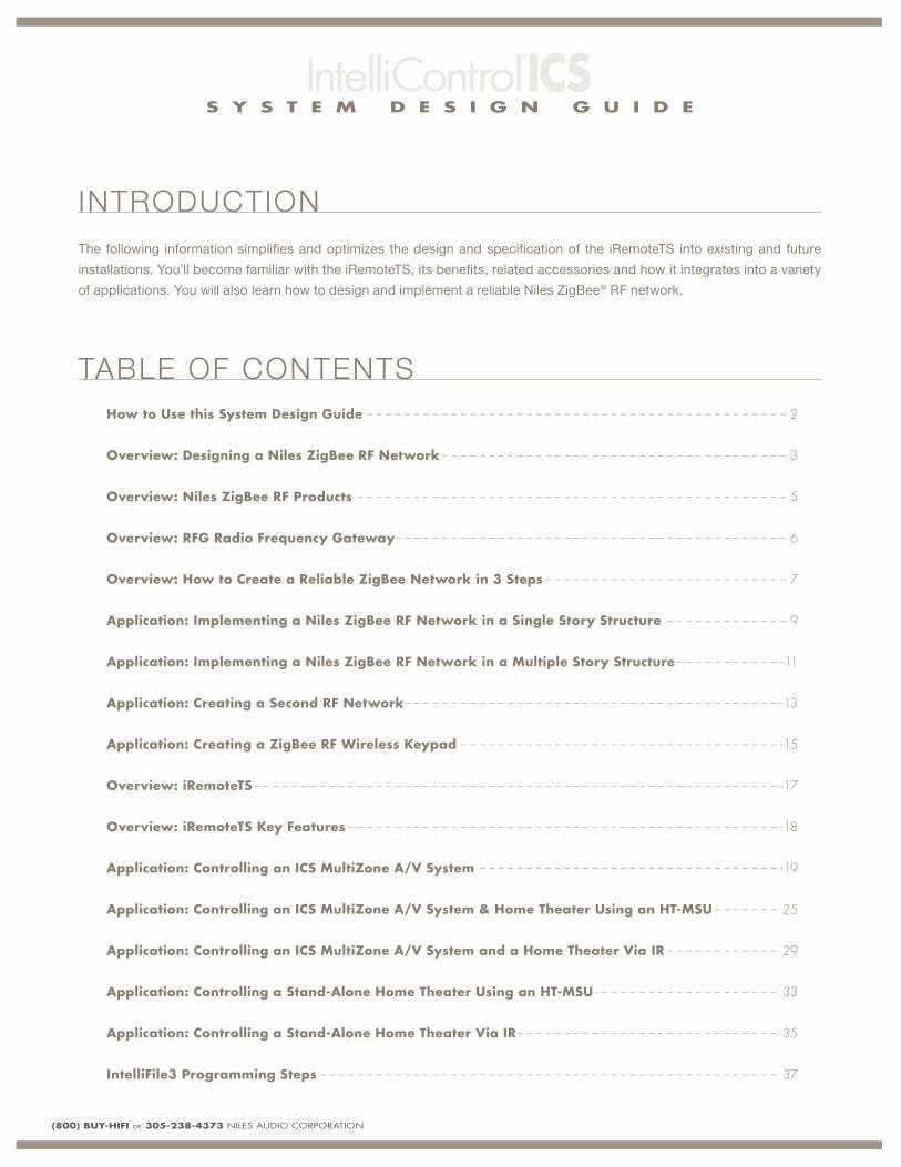
SYSTEM DESIGN GUIDE N I L E S A U D I O C O R P O R A T I O N I CS I N C L U D E S: • DESIGNING AND IMPLEMENTING A NILES ZIGBEE ® RF NETWORK • iREMOTE ® TS APPLICATIONS • INTEGRATING HOME THEATER CONTROL • INTELLIFILE ® 3 PROGRAMMING OVERVIEW VOLUME 1
Transcript of NILES AUDIO CORPORATION
SYSTEM DESIGN GUIDE
N I L E S A U D I O C O R P O R A T I O N
ICSI N C L U D E S :
• DESIGNING AND IMPLEMENTING A NILES ZIGBEE® RF NETWORK
• iREMOTE®TS APPLICATIONS
• INTEGRATING HOME THEATER CONTROL
• INTELL IF ILE®3 PROGRAMMING OVERVIEW
V O L U M E 1
S Y S T E M D E S I G N G U I D E
(800) BUY-HIFI or 305-238-4373 NILES AUDIO CORPORATION
The following information simplifi es and optimizes the design and specifi cation of the iRemoteTS into existing and future
installations. You’ll become familiar with the iRemoteTS, its benefi ts, related accessories and how it integrates into a variety
of applications. You will also learn how to design and implement a reliable Niles ZigBee® RF network.
INTRODUCTION
TABLE OF CONTENTS
How to Use this System Design Guide -- -- -- -- -- -- -- -- -- -- -- -- -- -- -- -- -- -- -- -- -- -- -- -- -- -- -- -- -- -- -- -- -- -- -- -- -- -- -- -- -- -- -- -- -- 2
Overview: Designing a Niles ZigBee RF Network -- -- -- -- -- -- -- -- -- -- -- -- -- -- -- -- -- -- -- -- -- -- -- -- -- -- -- -- -- -- -- -- -- -- -- -- -- 3
Overview: Niles ZigBee RF Products -- -- -- -- -- -- -- -- -- -- -- -- -- -- -- -- -- -- -- -- -- -- -- -- -- -- -- -- -- -- -- -- -- -- -- -- -- -- -- -- -- -- -- -- -- -- 5
Overview: RFG Radio Frequency Gateway-- -- -- -- -- -- -- -- -- -- -- -- -- -- -- -- -- -- -- -- -- -- -- -- -- -- -- -- -- -- -- -- -- -- -- -- -- -- -- -- -- -- 6
Overview: How to Create a Reliable ZigBee Network in 3 Steps -- -- -- -- -- -- -- -- -- -- -- -- -- -- -- -- -- -- -- -- -- -- -- -- -- -- 7
Application: Implementing a Niles ZigBee RF Network in a Single Story Structure -- -- -- -- -- -- -- -- -- -- -- -- -- 9
Application: Implementing a Niles ZigBee RF Network in a Multiple Story Structure -- -- -- -- -- -- -- -- -- -- -- -11
Application: Creating a Second RF Network -- -- -- -- -- -- -- -- -- -- -- -- -- -- -- -- -- -- -- -- -- -- -- -- -- -- -- -- -- -- -- -- -- -- -- -- -- -- -- -- -13
Application: Creating a ZigBee RF Wireless Keypad -- -- -- -- -- -- -- -- -- -- -- -- -- -- -- -- -- -- -- -- -- -- -- -- -- -- -- -- -- -- -- -- -- -- -15
Overview: iRemoteTS -- -- -- -- -- -- -- -- -- -- -- -- -- -- -- -- -- -- -- -- -- -- -- -- -- -- -- -- -- -- -- -- -- -- -- -- -- -- -- -- -- -- -- -- -- -- -- -- -- -- -- -- -- -- -- -- -17
Overview: iRemoteTS Key Features -- -- -- -- -- -- -- -- -- -- -- -- -- -- -- -- -- -- -- -- -- -- -- -- -- -- -- -- -- -- -- -- -- -- -- -- -- -- -- -- -- -- -- -- -- -- -18
Application: Controlling an ICS MultiZone A/V System -- -- -- -- -- -- -- -- -- -- -- -- -- -- -- -- -- -- -- -- -- -- -- -- -- -- -- -- -- -- -- -- -19
Application: Controlling an ICS MultiZone A/V System & Home Theater Using an HT-MSU -- -- -- -- -- -- -- 25
Application: Controlling an ICS MultiZone A/V System and a Home Theater Via IR -- -- -- -- -- -- -- -- -- -- -- -- 29
Application: Controlling a Stand-Alone Home Theater Using an HT-MSU - -- -- -- -- -- -- -- -- -- -- -- -- -- -- -- -- -- -- -- 33
Application: Controlling a Stand-Alone Home Theater Via IR -- -- -- -- -- -- -- -- -- -- -- -- -- -- -- -- -- -- -- -- -- -- -- -- -- -- -- -- 35
IntelliFile3 Programming Steps -- -- -- -- -- -- -- -- -- -- -- -- -- -- -- -- -- -- -- -- -- -- -- -- -- -- -- -- -- -- -- -- -- -- -- -- -- -- -- -- -- -- -- -- -- -- -- -- -- 37

S Y S T E M D E S I G N G U I D E
(800) BUY-HIFI or 305-238-4373 NILES AUDIO CORPORATION 2
HOW TO USE THIS SYSTEM DESIGN GUIDE
Do This First
Installation instructions on
what you need to know
before you begin
What Does this
Application Do?
Description of application
Critical Knowledge
These are “must know”
details that you need
to know
Key Considerations
Important information that
you need to consider when
planning your design
Installation Requirements
Specifi c installation details
that you need to know
Customer Benefits
What this application
does for your customer
Installer Benefits
What the application
does for you
Each chapter in the System Design Guide is broken up into sections to make comprehension easier. Each section contains
specifi c information that is presented with graphic examples to further aid in understanding. Below is a description of what
information is contained within each section.
The Overview
section provides
basic knowledge
about the topic.
The Application
section provides you
with detailed info for
a specifi c application
(see below)
The Cable Schedule
section lists all cables
used in cabling diagrams
(sometimes shown on
application page)
The Cable Diagram
section shows all
connection points
with color coded line
connections
S Y S T E M D E S I G N G U I D E
3 (800) BUY-HIFI or 305-238-4373 NILES AUDIO CORPORATION
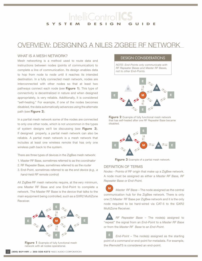
WHAT IS A MESH NETWORK?
Mesh networking is a method used to route data and
instructions between nodes (points of communication) to
complete a line of communication. Its design enables data
to hop from node to node until it reaches its intended
destination. In a fully connected mesh network, nodes are
interconnected with other nodes so that at least two
pathways connect each node (see Figure 1). This type of
connectivity is decentralized in nature and when designed
appropriately, is very reliable. Additionally, it is considered
“self-healing.” For example, if one of the nodes becomes
disabled, the data automatically advances using the alternate
path (see Figure 2).
In a partial mesh network some of the nodes are connected
to only one other node, which is not uncommon in the types
of system designs we’ll be discussing (see Figure 3).
If designed properly, a partial mesh network can also be
reliable. A partial mesh network is a mesh network that
includes at least one wireless remote that has only one
wireless path back to the system.
There are three types of devices in the ZigBee mesh network:
1. Master RF Base, sometimes referred to as the coordinator
2. RF Repeater Base, sometimes referred to as the router
3. End-Point, sometimes referred to as the end device (e.g., a
hand-held RF remote control)
All ZigBee RF mesh networks require, at the very minimum,
one Master RF Base and one End-Point to complete a
network. The Master RF Base is the device that talks to the
main equipment being controlled, such as a GXR2 MultiZone
Receiver.
DEFINITION OF TERMS
Nodes - Points of RF origin that make up a ZigBee network.
A node must be assigned as either a Master RF Base, RF
Repeater Base or End-Point.
Master RF Base – The node assigned as the central
communication hub for the ZigBee network. There is only
one (1) Master RF Base per ZigBee network and it is the only
node required to be hard-wired via CAT-5 to the GXR2
MultiZone Receiver.
RF Repeater Base – The node(s) assigned to
“repeat” the signal from an End-Point to a Master RF Base
or from the Master RF Base to an End-Point.
End-Point – The node(s) assigned as the starting
point of a command or end-point for metadata. For example,
the iRemoteTS is considered an end-point.
OVERVIEW: DESIGNING A NILES ZIGBEE RF NETWORK
E
E E
R
R
RM
Figure 3 Example of a partial mesh network.
Figure 1 Example of fully functional mesh
network with all nodes operational.
E
E
E E
R
R
R
R
M
Figure 2 Example of fully functional mesh network
that has self-healed after one RF Repeater Base became
disabled.
E
E
E E
R
R
R
R
M
M
E
R
DESIGN CONSIDERATIONS
NOTE: End-Points only communicate with
RF Repeater Bases and Master RF Bases,
not to other End-Points.
S Y S T E M D E S I G N G U I D E
(800) BUY-HIFI or 305-238-4373 NILES AUDIO CORPORATION 4
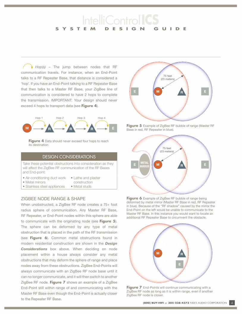
Hop(s) – The jump between nodes that RF
communication travels. For instance, when an End-Point
talks to a RF Repeater Base, that distance is considered a
‘hop’. If you have an End-Point talking to a RF Repeater Base
that then talks to a Master RF Base, your ZigBee line of
communication is considered to have 2 hops to complete
the transmission. IMPORTANT: Your design should never
exceed 4 hops to transport data (see Figure 4).
ZIGBEE NODE RANGE & SHAPE
When unobstructed, a ZigBee RF node creates a 75+ foot
radius sphere of communication. Any Master RF Base,
RF Repeater, or End-Point nodes within this sphere are able
to communicate with the originating node (see Figure 5).
The sphere can be deformed by any type of metal
obstruction that is placed in the path of the RF transmission
(see Figure 6). Common metal obstructions found in
modern residential construction are shown in the Design
Considerations box above. When deciding on node
placement within a house always consider any metal
obstructions that may deform the sphere of range and place
nodes away from these obstructions. ZigBee End-Points will
always communicate with an ZigBee RF node base until it
can no longer communicate, and it will then switch to another
ZigBee RF node. Figure 7 shows an example of a ZigBee
End-Point still within range of and communicating with the
Master RF Base even though the End-Point is actually closer
to the Repeater RF Base.
Hop 1 Hop 2
M
Hop 3 Hop 4
E
Figure 4 Data should never exceed four hops to reach
its destination
DESIGN CONSIDERATIONS
Take these potential obstructions into consideration as they
will affect the ZigBee RF communication of the RF Bases
and End-point:
• Air-conditioning duct work
• Metal mirrors
• Stainless steel appliances
• Lathe and plaster
construction
• Metal studs
R R RFigure 5 Example of ZigBee RF bubble of range (Master RF
Base in red, RF Repeater in blue).
75 feet
(23 meters)
ME R E
Figure 6 Example of ZigBee RF bubble of range being
deformed by metal mirror (Master RF Base in red, RF Repeater
in blue). Because of the “RF shadow” caused by the mirror the
End-Point on the left would be unable to communicate to the
Master RF Base. In this instance you would want to locate an
additional RF Repeater Base to circumvent the obstacle.
METAL
MIRRORME R E
75 feet
(23 meters)
Figure 7 End-Points will continue communicating with a
ZigBee RF node as long as it is within range, even if another
ZigBee RF node is closer.
M R
E

S Y S T E M D E S I G N G U I D E
5 (800) BUY-HIFI or 305-238-4373 NILES AUDIO CORPORATION
Product Model Stock No. DescriptionMaster RF
BaseRF Repeater Base End-Point
RFG FG01407Radio Frequency Gateway
(stand alone ZigBee Node)X X X1
RBX-1 FG01269 iRemote Charging Base X X
iRemote®
RHS-1FG01270 Wireless Remote X
iRemoteTS FG01341Wireless Color
TouchscreenX
HT-MSU FG01343Home Theater Main
System UnitX2 X3
1 When used to make a keypad wireless.
2 The HT-MSU functions as a Master RF Base when used in a stand-alone application (no connections to GXR2).3 Build 140 or greater of IntelliFile 3 allows the HT-MSU to function as a RF Repeater Base.
OVERVIEW: NILES ZIGBEE RF PRODUCTS
Below are the available Niles ZigBee RF products and the node they are able to function as. As you can see, some devices
are dedicated as End-Points (i.e., iRemote® Handset and iRemoteTS). Other devices can be confi gured to operate as a
Master RF Base, a RF Repeater Base, or an End-Point. Unlike the iRemote, the iRemoteTS DOES NOT contain a ZigBee RF
radio in its charging base.
S Y S T E M D E S I G N G U I D E
(800) BUY-HIFI or 305-238-4373 NILES AUDIO CORPORATION 6
RFGRadio Frequency
Gateway
MAKE SURE THE EXTERNAL ANTENNA IS ALWAYS ORIENTED VERTICALLY
RFGRadio Frequency
Gateway
MAKE SURE THE EXTERNAL ANTENNA IS ALWAYS ORIENTED VERTICALLY
RFGRadio Frequency
Gateway
MAKE SURE THE EXTERNAL ANTENNA IS ALWAYS ORIENTED VERTICALLY
RFGRadio Frequency
Gateway
MAKE SURE THE EXTERNAL ANTENNA IS ALWAYS ORIENTED VERTICALLY
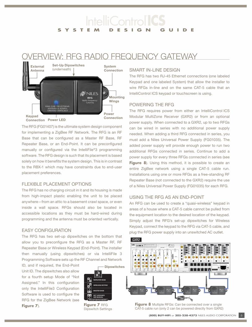
The RFG (FG01407) is the ultimate system design component
for implementing a ZigBee RF Network. The RFG is an RF
Base that can be confi gured as a Master RF Base, RF
Repeater Base, or an End-Point. It can be preconfi gured
manually or confi gured via the IntelliFile®3 programming
software. The RFG design is such that its placement is based
solely on how it benefi ts the system design. This is in contrast
to the RBX-1 which may have constraints due to end-user
placement preferences.
FLEXIBLE PLACEMENT OPTIONS
The RFG has no charging circuit in it and its housing is made
from high-impact plastic enabling the unit to be placed
anywhere—from an attic to a basement crawl space, or even
inside a wall space. RFGs should also be located in
accessible locations as they must be hard-wired during
programming and the antenna must be oriented vertically.
EASY CONFIGURATION
The RFG has two set-up dipswitches on the bottom that
allow you to preconfi gure the RFG as a Master RF, RF
Repeater Base or Wireless Keypad (End-Point). The installer
then manually (using dipswitches) or via IntelliFile 3
Programming Software sets up the RF Channel and Network
ID, and if required, the End-Point
Unit ID. The dipswitches also allow
for a fourth setup Mode of “Not
Assigned.” In this confi guration
only the IntelliFile3 Confi guration
Software is used to confi gure the
RFG for the ZigBee Network (see
Figure 7).
SMART IN-LINE DESIGN
The RFG has two RJ-45 Ethernet connections (one labeled
Keypad and one labeled System) that allow the installer to
wire RFGs in-line and on the same CAT-5 cable that an
IntelliControl ICS keypad or touchscreen is using.
POWERING THE RFG
The RFG requires power from either an IntelliControl ICS
Modular MultiZone Receiver (GXR2) or from an optional
power supply. When connected to a GXR2, up to two RFGs
can be wired in series with no additional power supply
needed. When adding a third RFG connected in series, you
must add a Niles Universal Power Supply (FG01035). The
added power supply will provide enough power to run two
additional RFGs connected in series. Continue to add a
power supply for every three RFGs connected in series (see
Figure 8). Using this method, it is possible to create an
entire ZigBee network using a single CAT-5 cable run.
Installations using one or more RFGs as a free-standing RF
Repeater Base (not connected to the GXR2) require the use
of a Niles Universal Power Supply (FG01035) for each RFG.
USING THE RFG AS AN END-POINT
An RFG can be used to create a “quasi-wireless” keypad in
areas of a house where a CAT-5 cable cannot be pulled from
the equipment location to the desired location of the keypad.
Simply adjust the RFG’s set-up dipswitches for Wireless
Keypad, connect the keypad to the RFG via CAT-5 cable, and
plug the RFG power supply into an unswitched AC outlet.
OVERVIEW: RFG RADIO FREQUENCY GATEWAY
COMMUNICATION & CONTROL SWITCH
VIDEOOUT
CASCADE AUDIOOUT
FMANT
TM-H
D/R
AMANT
L R
CASCADE AUDIOOUT
Niles A
udio Corporation M
iami Florida, U
SA
IM-N
ETN
iles Audio C
orporation Miam
i Florida, USA
L R
L R
CASCADE AUDIOOUT
AUDIOIN
IR OUT
NETWORKDEVICE
IR IN
VIDEOOUT
CASCADE AUDIOOUT
GXR2
Power LED
System
Connection
Keypad
Connection
Power
Connection
Mounting
Wings
Set-Up Dipswitches
(underneath)
Figure 8 Multiple RFGs: Can be connected over a single
CAT-5 cable run (only 2 can be powered directly from GXR2)
Dipswitches
REPEATER BASE
WIRELESS KEYPAD
MASTER BASE
RFG DIP SWITCH MODES
NOT ASSIGNED
SEE MANUAL
1 2
ON
Figure 7 RFG
Dipswitch Settings
External
Antenna
S Y S T E M D E S I G N G U I D E
7 (800) BUY-HIFI or 305-238-4373 NILES AUDIO CORPORATION
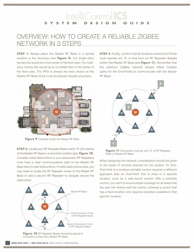
STEP 1: Always place the Master RF Base in a central
location in the structure (see Figure 9). For single-story
homes this would be in the center of the fl oor plan. For multi-
story homes this would be on a middle fl oor in the center of
the fl oor plan. The RFG is always the best choice as the
Master RF Base since it can be placed virtually anywhere.
STEP 2: Locate your RF Repeater Bases within 75' (23 meters)
of the Master RF Base in a concentric pattern (see Figure 10).
Consider metal obstructions in your placement. RF Repeaters
must have a clear communications path to the Master RF
Base free of metal obstructions. If metal obstructions exist, you
may need to locate the RF Repeater closer to the Master RF
Base or add a second RF Repeater to navigate around the
obstruction.
STEP 3: Finally, confi rm that all locations where End-Points
must operate are 75' or less from an RF Repeater Base(s)
and/or the Master RF Base (see Figure 11). Remember that
the optimum ZigBee network always offers multiple
paths for the End-Points to communicate with the Master
RF Base.
When designing the network, consideration should be given
to the types of controls planned for the system. An End-
Point that is a wireless portable control requires a different
approach than an End-Point that is fi xed in a specifi c
location, such as a wall-mount control. With a portable
control, you want to ensure ample coverage for all areas that
the user will venture with the control, whereas a control that
has a fi xed location only requires reception available to that
specifi c location.
M
Master RF Base
First Concentric Circle of RF Repeater Bases
Second Concentric Circle of RF Repeater Bases
M
R
R
RR
R
R R
R
M
R
R
RR
R
R R
R
< 75'
< 75'
E
E
E
Figure 9 Centrally locate the Master RF Base.
Figure 10 RF Repeater Bases should be placed in
concentric circles from Master RF Base.
Figure 11 End-points must be with 75' of RF Repeater
Base or Master RF Base.
OVERVIEW: HOW TO CREATE A RELIABLE ZIGBEE NETWORK IN 3 STEPS
< 75'
< 75'
S Y S T E M D E S I G N G U I D E
(800) BUY-HIFI or 305-238-4373 NILES AUDIO CORPORATION 8
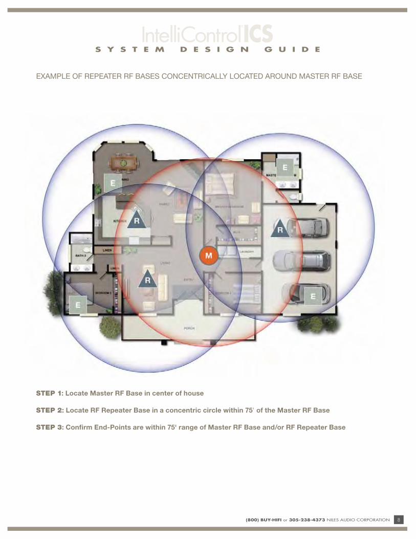
STEP 1: Locate Master RF Base in center of house
STEP 2: Locate RF Repeater Base in a concentric circle within 75' of the Master RF Base
STEP 3: Confirm End-Points are within 75' range of Master RF Base and/or RF Repeater Base
EXAMPLE OF REPEATER RF BASES CONCENTRICALLY LOCATED AROUND MASTER RF BASE

S Y S T E M D E S I G N G U I D E
9 (800) BUY-HIFI or 305-238-4373 NILES AUDIO CORPORATION
DO THIS FIRST
WHAT DOES THIS APPLICATION DO?A robust ZigBee RF network is required for our wireless products to function properly. This section demonstrates how to
optimally design and specify a ZigBee RF network in a single story structure.
Review the information on ZigBee RF networks on the preceding pages.
Key ConsiderationsPlanning a ZigBee RF network is a lot
like planning an automation system. With
an automation system, you need a solid
understanding of the equipment being
controlled to ensure reliable operation.
With a ZigBee RF network you need to
understand the environment in which
the RF network will be operating, in
particular, items that can affect reception
range such as home construction,
metal obstacles, appliances, etc. In
addition, you will benefi t greatly from
understanding basic system parameters
for the ZigBee RF network.
Key parameters include:
• Max number of Master RF Bases per
Network: ONE
• Max number of End-Points per Master
RF Base: TEN
• Max number of RF Repeater Bases
per Master RF Base: TEN
• Max number of “hops” within a
Network: FOUR
• Max number of networks: TWO
Customer Benefi tsYour customer will have access to all of
their playlists, artists and albums from
wireless controls and wired keypads.
The wireless controls will allow them to
roam the house and operate any audio
and/or video zone of the house or a
home theater, as well as have access to
all metadata from capable devices.
Installation Benefi tsA properly designed ZigBee RF network
will allow all of our wireless remote
products to function fl awlessly. In
addition, having a solid network in place
will create sales opportunities in the
future by providing an infrastructure for
add-on products.
CRITICAL KNOWLEDGE
1. All wireless devices must be hard-
wired during programming of the
IntelliControl ICS system.
2. The Master RF Base must be hard-
wired to ICS system at all times.
3. When multiple RFGs are connected
in series using a single CAT-5
cable all RF Repeater Base
communication is performed via
RF (4 hop maximum rule applies).
The CAT-5 is used for power and
programming only (2 RFGs can be
powered directly by the GXR2).
4. The antenna of the RFG must
be oriented vertically for proper
operation.
APPLICATION: IMPLEMENTING A NILES ZIGBEE RF NETWORK IN A SINGLE STORY STRUCTURE
INSTALLATION REQUIREMENTS
• One Master RF Base
• At least one End-Point
• RF Repeater must be within 75' of
the Master RF Base
• After programming with IntelliFile3,
perform a “Reset Net” from one
wireless remote.
S Y S T E M D E S I G N G U I D E
(800) BUY-HIFI or 305-238-4373 NILES AUDIO CORPORATION 10
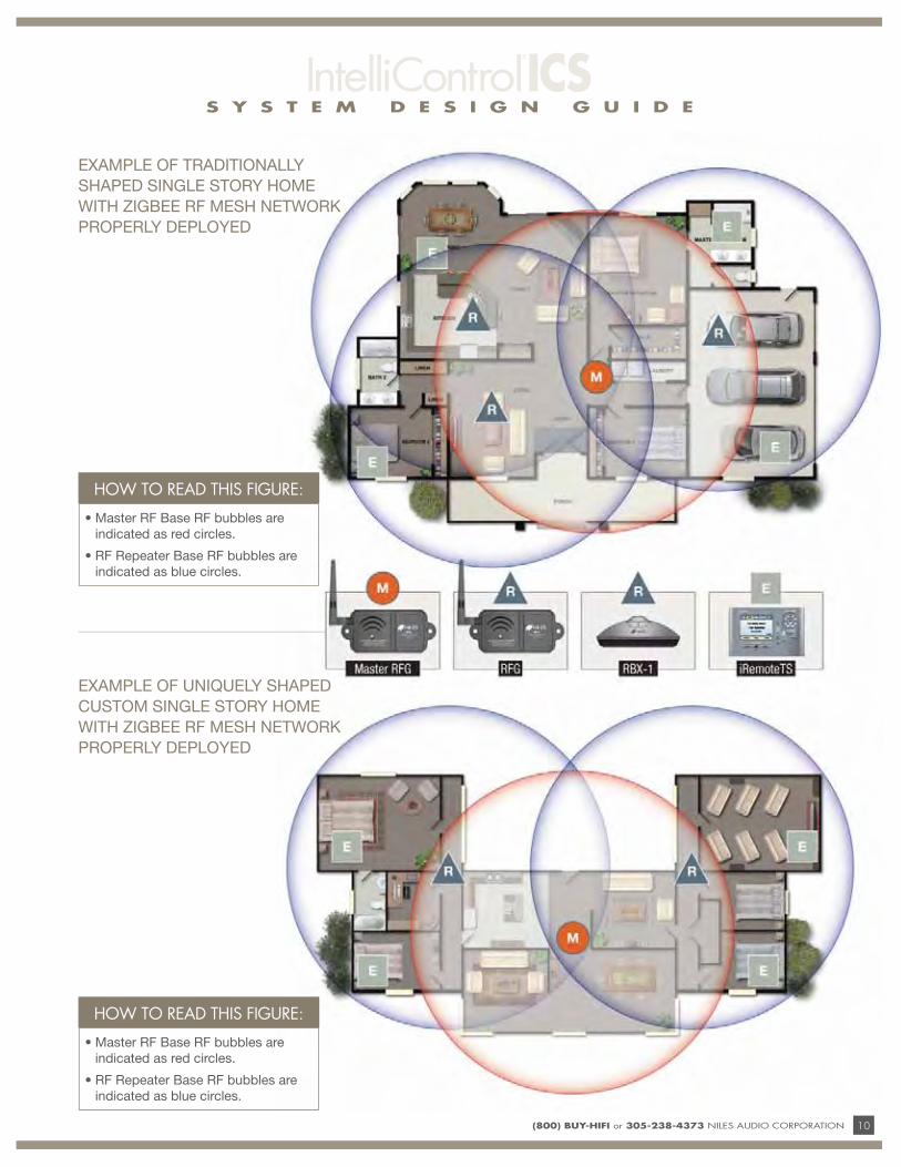
EXAMPLE OF TRADITIONALLY
SHAPED SINGLE STORY HOME
WITH ZIGBEE RF MESH NETWORK
PROPERLY DEPLOYED
EXAMPLE OF UNIQUELY SHAPED
CUSTOM SINGLE STORY HOME
WITH ZIGBEE RF MESH NETWORK
PROPERLY DEPLOYED
HOW TO READ THIS FIGURE:
• Master RF Base RF bubbles are
indicated as red circles.
• RF Repeater Base RF bubbles are
indicated as blue circles.
HOW TO READ THIS FIGURE:
• Master RF Base RF bubbles are
indicated as red circles.
• RF Repeater Base RF bubbles are
indicated as blue circles.

S Y S T E M D E S I G N G U I D E
11 (800) BUY-HIFI or 305-238-4373 NILES AUDIO CORPORATION
WHAT DOES THIS APPLICATION DO?A robust ZigBee RF network is required for many of our wireless products to function properly. This section demonstrates how to
optimally design and specify a ZigBee RF network in a multi-story structure.
DO THIS FIRST Review the information on ZigBee RF networks on the preceding pages.
CRITICAL KNOWLEDGE
1. When deploying a Niles ZigBee
network in a multi-story structure
you must know what type of
construction is used between fl oors.
2. All wireless devices must be hard-
wired during programming of the
IntelliControl ICS system.
3. The Master RF Base must be hard-
wired to ICS system at all times.
4. When multiple RFGs are connected
in series using a single CAT-5
cable all RF Repeater Base
communication is performed via
RF (4 hop maximum rule applies).
The CAT-5 is used for power and
programming only (2 RFGs can be
powered directly by the GXR2).
5. The antenna of the RFG must
be oriented vertically for proper
operation.
Key ConsiderationsWhen deploying a Niles ZigBee RF
network in a multi-story structure you
must know what type of construction
is used between fl oors. Traditional
wood construction will pass ZigBee
RF signals with minimal reduction in
range. Laminate beams can cause
additional loss of range. Finally, steel
i-beams and pre-engineered concrete
can greatly reduce or completely block
ZigBee RF transmissions. In this type of
construction creating two networks is
recommended.
Key parameters include:
• Max number of Master RF Bases per
Network: ONE
• Max number of End-Points per Master
RF Base: TEN
• Max number of RF Repeater Bases
per Master RF Base: TEN
• Max number of “hops” within a
Network: FOUR
• Max number of networks: TWO
Customer Benefi tsYour customer will have access to all of
their playlists, artists and albums from
wireless controls and wired keypads.
The wireless controls will allow them to
roam the house and operate any audio
and/or video zone of the house or a
home theater, as well as have access to
all metadata from capable devices.
Installation Benefi tsA properly designed ZigBee RF network
will allow all of our wireless remote
products to function fl awlessly. In
addition, having a solid network in place
will create sales opportunities in the
future by providing an infrastructure for
add-on products.
APPLICATION: IMPLEMENTING A NILES ZIGBEE RF NETWORK IN A MULTIPLE STORY STRUCTURE
INSTALLATION REQUIREMENTS
• One Master RF Base
• At least one End-Point
• RF Repeater must be within 75' of
the Master RF Base
S Y S T E M D E S I G N G U I D E
(800) BUY-HIFI or 305-238-4373 NILES AUDIO CORPORATION 12
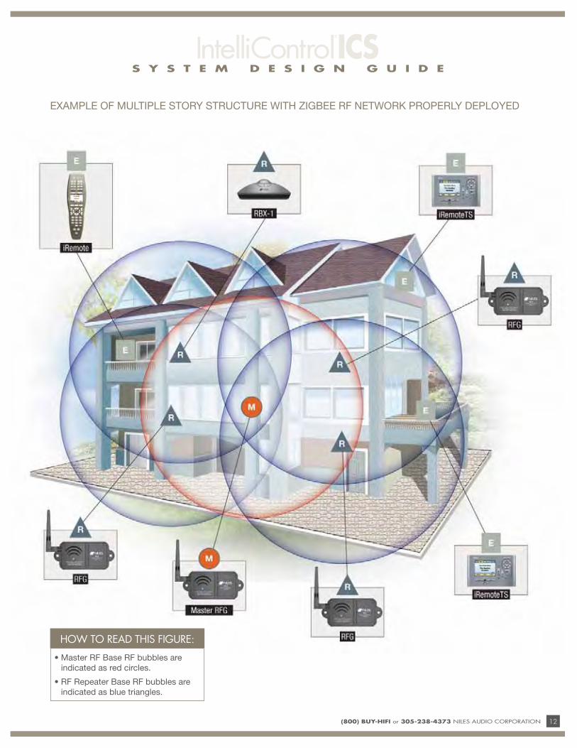
EXAMPLE OF MULTIPLE STORY STRUCTURE WITH ZIGBEE RF NETWORK PROPERLY DEPLOYED
HOW TO READ THIS FIGURE:
• Master RF Base RF bubbles are
indicated as red circles.
• RF Repeater Base RF bubbles are
indicated as blue triangles.
S Y S T E M D E S I G N G U I D E
13 (800) BUY-HIFI or 305-238-4373 NILES AUDIO CORPORATION
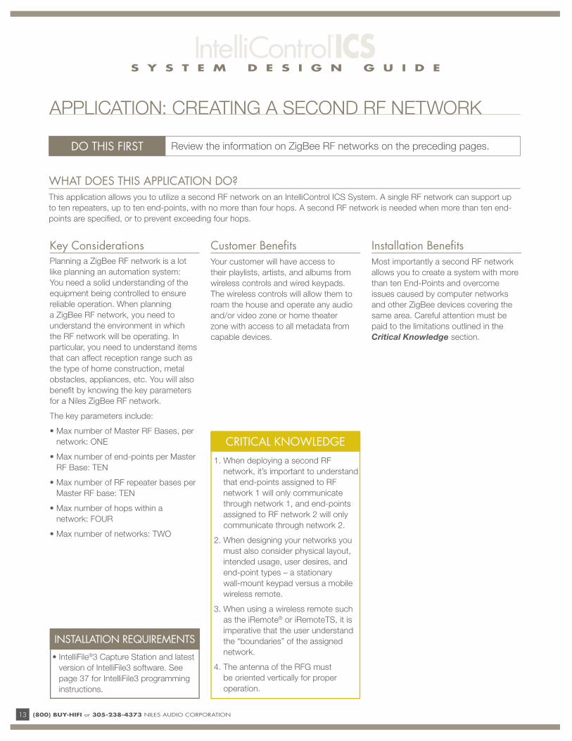
WHAT DOES THIS APPLICATION DO?This application allows you to utilize a second RF network on an IntelliControl ICS System. A single RF network can support up
to ten repeaters, up to ten end-points, with no more than four hops. A second RF network is needed when more than ten end-
points are specifi ed, or to prevent exceeding four hops.
DO THIS FIRST Review the information on ZigBee RF networks on the preceding pages.
Planning a ZigBee RF network is a lot
like planning an automation system:
You need a solid understanding of the
equipment being controlled to ensure
reliable operation. When planning
a ZigBee RF network, you need to
understand the environment in which
the RF network will be operating. In
particular, you need to understand items
that can affect reception range such as
the type of home construction, metal
obstacles, appliances, etc. You will also
benefi t by knowing the key parameters
for a Niles ZigBee RF network.
The key parameters include:
• Max number of Master RF Bases, per
network: ONE
• Max number of end-points per Master
RF Base: TEN
• Max number of RF repeater bases per
Master RF base: TEN
• Max number of hops within a
network: FOUR
• Max number of networks: TWO
Customer Benefi tsYour customer will have access to
their playlists, artists, and albums from
wireless controls and wired keypads.
The wireless controls will allow them to
roam the house and operate any audio
and/or video zone or home theater
zone with access to all metadata from
capable devices.
Installation Benefi tsMost importantly a second RF network
allows you to create a system with more
than ten End-Points and overcome
issues caused by computer networks
and other ZigBee devices covering the
same area. Careful attention must be
paid to the limitations outlined in the
Critical Knowledge section.
APPLICATION: CREATING A SECOND RF NETWORK
CRITICAL KNOWLEDGE
1. When deploying a second RF
network, it’s important to understand
that end-points assigned to RF
network 1 will only communicate
through network 1, and end-points
assigned to RF network 2 will only
communicate through network 2.
2. When designing your networks you
must also consider physical layout,
intended usage, user desires, and
end-point types – a stationary
wall-mount keypad versus a mobile
wireless remote.
3. When using a wireless remote such
as the iRemote® or iRemoteTS, it is
imperative that the user understand
the “boundaries” of the assigned
network.
4. The antenna of the RFG must
be oriented vertically for proper
operation.
Key Considerations
INSTALLATION REQUIREMENTS
• IntelliFile®3 Capture Station and latest
version of IntelliFile3 software. See
page 37 for IntelliFile3 programming
instructions.
S Y S T E M D E S I G N G U I D E
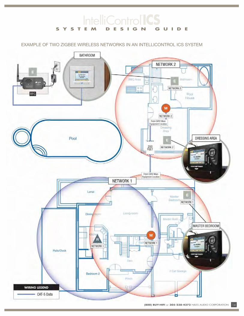
(800) BUY-HIFI or 305-238-4373 NILES AUDIO CORPORATION 14
EXAMPLE OF TWO ZIGBEE WIRELESS NETWORKS IN AN INTELLICONTROL ICS SYSTEM
S Y S T E M D E S I G N G U I D E
15 (800) BUY-HIFI or 305-238-4373 NILES AUDIO CORPORATION
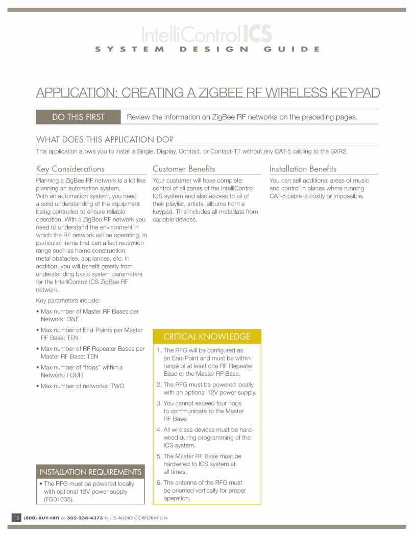
WHAT DOES THIS APPLICATION DO?This application allows you to install a Single, Display, Contact, or Contact-TT without any CAT-5 cabling to the GXR2.
DO THIS FIRST Review the information on ZigBee RF networks on the preceding pages.
CRITICAL KNOWLEDGE
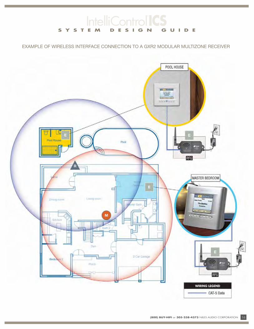
1. The RFG will be confi gured as
an End-Point and must be within
range of at least one RF Repeater
Base or the Master RF Base.
2. The RFG must be powered locally
with an optional 12V power supply.
3. You cannot exceed four hops
to communicate to the Master
RF Base.
4. All wireless devices must be hard-
wired during programming of the
ICS system.
5. The Master RF Base must be
hardwired to ICS system at
all times.
6. The antenna of the RFG must
be oriented vertically for proper
operation.
Key ConsiderationsPlanning a ZigBee RF network is a lot like
planning an automation system.
With an automation system, you need
a solid understanding of the equipment
being controlled to ensure reliable
operation. With a ZigBee RF network you
need to understand the environment in
which the RF network will be operating, in
particular, items that can affect reception
range such as home construction,
metal obstacles, appliances, etc. In
addition, you will benefi t greatly from
understanding basic system parameters
for the IntelliControl ICS ZigBee RF
network.
Key parameters include:
• Max number of Master RF Bases per
Network: ONE
• Max number of End-Points per Master
RF Base: TEN
• Max number of RF Repeater Bases per
Master RF Base: TEN
• Max number of “hops” within a
Network: FOUR
• Max number of networks: TWO
Customer Benefi tsYour customer will have complete
control of all zones of the IntelliControl
ICS system and also access to all of
their playlist, artists, albums from a
keypad. This includes all metadata from
capable devices.
Installation Benefi tsYou can sell additional areas of music
and control in places where running
CAT-5 cable is costly or impossible.
APPLICATION: CREATING A ZIGBEE RF WIRELESS KEYPAD
INSTALLATION REQUIREMENTS
• The RFG must be powered locally
with optional 12V power supply
(FG01035).
S Y S T E M D E S I G N G U I D E
(800) BUY-HIFI or 305-238-4373 NILES AUDIO CORPORATION 16
EXAMPLE OF WIRELESS INTERFACE CONNECTION TO A GXR2 MODULAR MULTIZONE RECEIVER
S Y S T E M D E S I G N G U I D E
17 (800) BUY-HIFI or 305-238-4373 NILES AUDIO CORPORATION
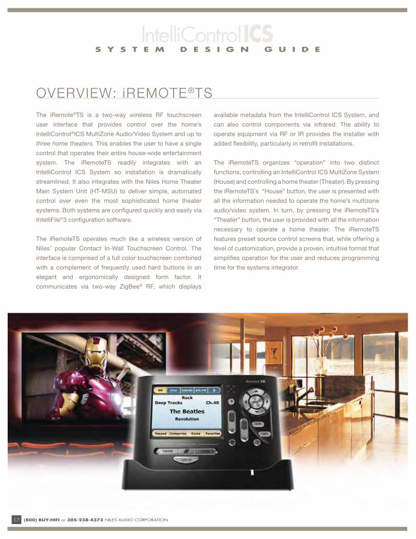
The iRemote®TS is a two-way wireless RF touchscreen
user interface that provides control over the home’s
IntelliControl®ICS MultiZone Audio/Video System and up to
three home theaters. This enables the user to have a single
control that operates their entire house-wide entertainment
system. The iRemoteTS readily integrates with an
IntelliControl ICS System so installation is dramatically
streamlined. It also integrates with the Niles Home Theater
Main System Unit (HT-MSU) to deliver simple, automated
control over even the most sophisticated home theater
systems. Both systems are confi gured quickly and easily via
IntelliFile®3 confi guration software.
The iRemoteTS operates much like a wireless version of
Niles’ popular Contact In-Wall Touchscreen Control. The
interface is comprised of a full color touchscreen combined
with a complement of frequently used hard buttons in an
elegant and ergonomically designed form factor. It
communicates via two-way ZigBee® RF, which displays
available metadata from the IntelliControl ICS System, and
can also control components via infrared. The ability to
operate equipment via RF or IR provides the installer with
added fl exibility, particularly in retrofi t installations.
The iRemoteTS organizes “operation” into two distinct
functions, controlling an IntelliControl ICS MultiZone System
(House) and controlling a home theater (Theater). By pressing
the iRemoteTS’s “House” button, the user is presented with
all the information needed to operate the home’s multizone
audio/video system. In turn, by pressing the iRemoteTS’s
“Theater” button, the user is provided with all the information
necessary to operate a home theater. The iRemoteTS
features preset source control screens that, while offering a
level of customization, provide a proven, intuitive format that
simplifi es operation for the user and reduces programming
time for the systems integrator.
OVERVIEW: iREMOTE®TS
S Y S T E M D E S I G N G U I D E
(800) BUY-HIFI or 305-238-4373 NILES AUDIO CORPORATION 18
SINGLE UNIFYING CONTROL
The iRemoteTS simplifi es operation for the user by enabling
operation of both the multizone audio/video system and the
home theater(s) using a single intuitive user interface.
FLEXIBLE, INTELLIGENT SYSTEM
MANAGEMENT
The iRemoteTS is a control solution that is supported by a
robust system architecture that includes all the right
connections, which helps ensure that the system works as it
should each and every time. The systems integrator can
choose from a fl exible array of automation and control options
including RS-232 and IR when used with the Niles HT-MSU.
TWO-WAY ZIGBEE RF TECHNOLOGY
ZigBee RF communication provides a fl exible, reliable
method for communication. In addition, its two-way design
provides real-time system status and data to the user.
STREAMING METADATA SIMPLIFIES
OPERATION
The iRemoteTS displays menus, guides, favorite channel
lists, and tuner data required to operate today’s popular
digital sources.
THE PERFECT RETROFIT SOLUTION
Because the iRemoteTS doesn’t require a CAT-5 cable to
function, even homes originally wired with basic speaker
selectors and volume controls can be upgraded to an
IntelliControl ICS system. Your customer gets full access to all
of their artists, playlists, and albums—without any new wires!
DUAL IR/RF COMMUNICATION CAPABILITY
The ability to control equipment via Radio Frequency (RF)
and/or Infrared (IR) provides the installation professional
with added fl exibility when designing a system. For instance,
in situations where running an IR fl asher to a local component,
such as a fl at panel TV, doesn’t make sense for logistical or
aesthetic reasons, you can choose to operate the local
source via IR and send all other commands via RF.
TRUE PLUG-AND-PLAY INTEGRATION
The iRemoteTS delivers true plug-and-play integration.
Unlike conventional multizone systems, IntelliControl ICS’s
auto enumeration and auto confi guration enables the
iRemoteTS to automatically upload all system settings for
the IntelliControl ICS system to the iRemoteTS.
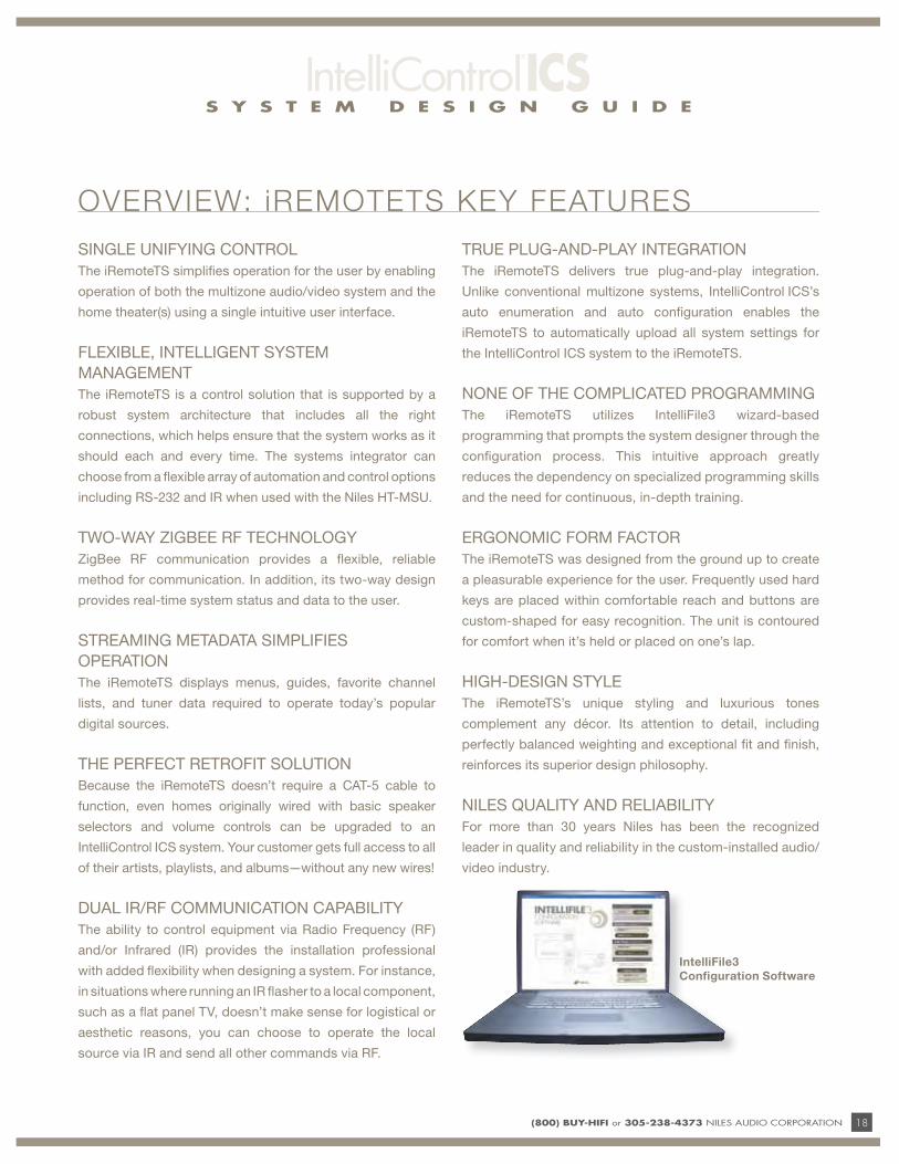
NONE OF THE COMPLICATED PROGRAMMING
The iRemoteTS utilizes IntelliFile3 wizard-based
programming that prompts the system designer through the
confi guration process. This intuitive approach greatly
reduces the dependency on specialized programming skills
and the need for continuous, in-depth training.
ERGONOMIC FORM FACTOR
The iRemoteTS was designed from the ground up to create
a pleasurable experience for the user. Frequently used hard
keys are placed within comfortable reach and buttons are
custom-shaped for easy recognition. The unit is contoured
for comfort when it’s held or placed on one’s lap.
HIGH-DESIGN STYLE
The iRemoteTS’s unique styling and luxurious tones
complement any décor. Its attention to detail, including
perfectly balanced weighting and exceptional fi t and fi nish,
reinforces its superior design philosophy.
NILES QUALITY AND RELIABILITY
For more than 30 years Niles has been the recognized
leader in quality and reliability in the custom-installed audio/
video industry.
OVERVIEW: iREMOTETS KEY FEATURES
IntelliFile3
Configuration Software
S Y S T E M D E S I G N G U I D E
19 (800) BUY-HIFI or 305-238-4373 NILES AUDIO CORPORATION
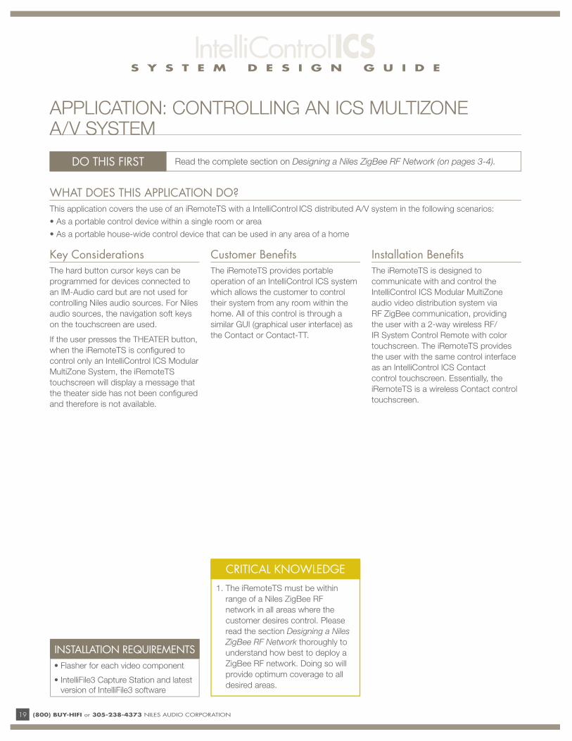
WHAT DOES THIS APPLICATION DO?This application covers the use of an iRemoteTS with a IntelliControl ICS distributed A/V system in the following scenarios:
• As a portable control device within a single room or area
• As a portable house-wide control device that can be used in any area of a home
DO THIS FIRST Read the complete section on Designing a Niles ZigBee RF Network (on pages 3-4).
Key ConsiderationsThe hard button cursor keys can be
programmed for devices connected to
an IM-Audio card but are not used for
controlling Niles audio sources. For Niles
audio sources, the navigation soft keys
on the touchscreen are used.
If the user presses the THEATER button,
when the iRemoteTS is confi gured to
control only an IntelliControl ICS Modular
MultiZone System, the iRemoteTS
touchscreen will display a message that
the theater side has not been confi gured
and therefore is not available.
Customer Benefi tsThe iRemoteTS provides portable
operation of an IntelliControl ICS system
which allows the customer to control
their system from any room within the
home. All of this control is through a
similar GUI (graphical user interface) as
the Contact or Contact-TT.
Installation Benefi tsThe iRemoteTS is designed to
communicate with and control the
IntelliControl ICS Modular MultiZone
audio video distribution system via
RF ZigBee communication, providing
the user with a 2-way wireless RF/
IR System Control Remote with color
touchscreen. The iRemoteTS provides
the user with the same control interface
as an IntelliControl ICS Contact
control touchscreen. Essentially, the
iRemoteTS is a wireless Contact control
touchscreen.
INSTALLATION REQUIREMENTS
• Flasher for each video component
• IntelliFile3 Capture Station and latest
version of IntelliFile3 software
APPLICATION: CONTROLLING AN ICS MULTIZONE A/V SYSTEM
CRITICAL KNOWLEDGE
1. The iRemoteTS must be within
range of a Niles ZigBee RF
network in all areas where the
customer desires control. Please
read the section Designing a Niles
ZigBee RF Network thoroughly to
understand how best to deploy a
ZigBee RF network. Doing so will
provide optimum coverage to all
desired areas.
S Y S T E M D E S I G N G U I D E
(800) BUY-HIFI or 305-238-4373 NILES AUDIO CORPORATION 20
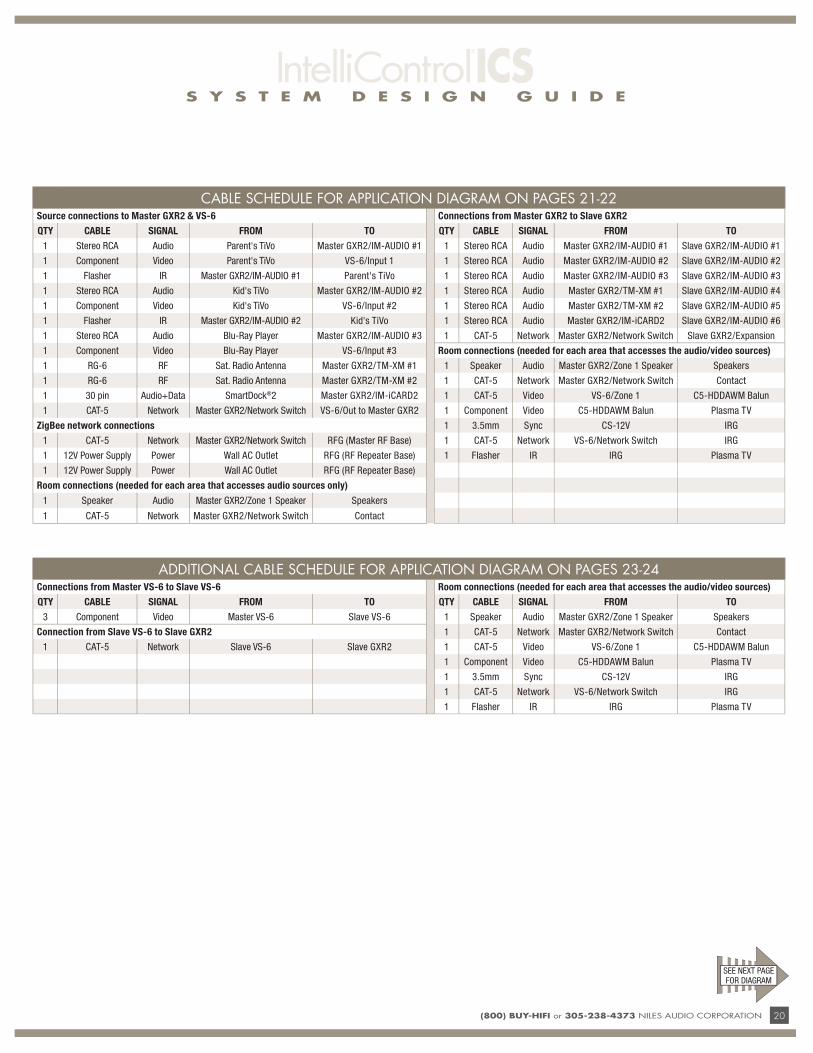
CABLE SCHEDULE FOR APPLICATION DIAGRAM ON PAGES 21-22Source connections to Master GXR2 & VS-6 Connections from Master GXR2 to Slave GXR2
QTY CABLE SIGNAL FROM TO QTY CABLE SIGNAL FROM TO
1 Stereo RCA Audio Parent's TiVo Master GXR2/IM-AUDIO #1 1 Stereo RCA Audio Master GXR2/IM-AUDIO #1 Slave GXR2/IM-AUDIO #1
1 Component Video Parent's TiVo VS-6/Input 1 1 Stereo RCA Audio Master GXR2/IM-AUDIO #2 Slave GXR2/IM-AUDIO #2
1 Flasher IR Master GXR2/IM-AUDIO #1 Parent's TiVo 1 Stereo RCA Audio Master GXR2/IM-AUDIO #3 Slave GXR2/IM-AUDIO #3
1 Stereo RCA Audio Kid's TiVo Master GXR2/IM-AUDIO #2 1 Stereo RCA Audio Master GXR2/TM-XM #1 Slave GXR2/IM-AUDIO #4
1 Component Video Kid's TiVo VS-6/Input #2 1 Stereo RCA Audio Master GXR2/TM-XM #2 Slave GXR2/IM-AUDIO #5
1 Flasher IR Master GXR2/IM-AUDIO #2 Kid's TiVo 1 Stereo RCA Audio Master GXR2/IM-iCARD2 Slave GXR2/IM-AUDIO #6
1 Stereo RCA Audio Blu-Ray Player Master GXR2/IM-AUDIO #3 1 CAT-5 Network Master GXR2/Network Switch Slave GXR2/Expansion
1 Component Video Blu-Ray Player VS-6/Input #3 Room connections (needed for each area that accesses the audio/video sources)
1 RG-6 RF Sat. Radio Antenna Master GXR2/TM-XM #1 1 Speaker Audio Master GXR2/Zone 1 Speaker Speakers
1 RG-6 RF Sat. Radio Antenna Master GXR2/TM-XM #2 1 CAT-5 Network Master GXR2/Network Switch Contact
1 30 pin Audio+Data SmartDock®2 Master GXR2/IM-iCARD2 1 CAT-5 Video VS-6/Zone 1 C5-HDDAWM Balun
1 CAT-5 Network Master GXR2/Network Switch VS-6/Out to Master GXR2 1 Component Video C5-HDDAWM Balun Plasma TV
ZigBee network connections 1 3.5mm Sync CS-12V IRG
1 CAT-5 Network Master GXR2/Network Switch RFG (Master RF Base) 1 CAT-5 Network VS-6/Network Switch IRG
1 12V Power Supply Power Wall AC Outlet RFG (RF Repeater Base) 1 Flasher IR IRG Plasma TV
1 12V Power Supply Power Wall AC Outlet RFG (RF Repeater Base)
Room connections (needed for each area that accesses audio sources only)
1 Speaker Audio Master GXR2/Zone 1 Speaker Speakers
1 CAT-5 Network Master GXR2/Network Switch Contact
SEE NEXT PAGE FOR DIAGRAM
ADDITIONAL CABLE SCHEDULE FOR APPLICATION DIAGRAM ON PAGES 23-24Connections from Master VS-6 to Slave VS-6 Room connections (needed for each area that accesses the audio/video sources)
QTY CABLE SIGNAL FROM TO QTY CABLE SIGNAL FROM TO
3 Component Video Master VS-6 Slave VS-6 1 Speaker Audio Master GXR2/Zone 1 Speaker Speakers
Connection from Slave VS-6 to Slave GXR2 1 CAT-5 Network Master GXR2/Network Switch Contact
1 CAT-5 Network Slave VS-6 Slave GXR2 1 CAT-5 Video VS-6/Zone 1 C5-HDDAWM Balun
1 Component Video C5-HDDAWM Balun Plasma TV
1 3.5mm Sync CS-12V IRG
1 CAT-5 Network VS-6/Network Switch IRG
1 Flasher IR IRG Plasma TV

s y s t e m d e s i g n g u i d e
21 (800) Buy-HiFi or 305-238-4373 NILES AUDIO CORPORATION
s y s t e m d e s i g n g u i d e
(800) Buy-HiFi or 305-238-4373 NILES AUDIO CORPORATION 22
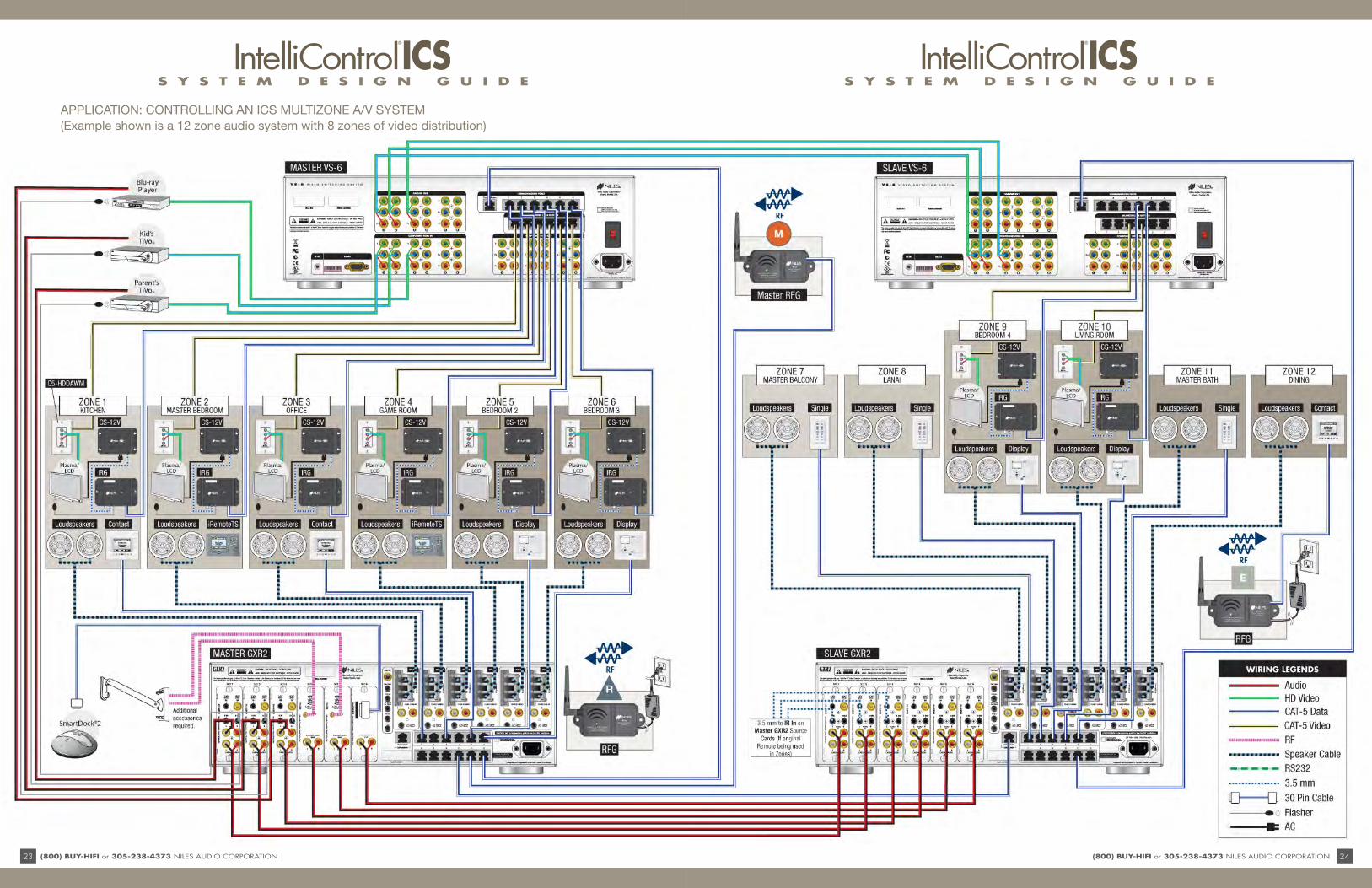
APPLICATION: CONTrOLLINg AN ICS MULTIZONE A/V SYSTEM (Example shown is a 12 zone audio system with 6 zones of video distribution)
s y s t e m d e s i g n g u i d e
23 (800) Buy-HiFi or 305-238-4373 NILES AUDIO CORPORATION
s y s t e m d e s i g n g u i d e
(800) Buy-HiFi or 305-238-4373 NILES AUDIO CORPORATION 24
APPLICATION: CONTrOLLINg AN ICS MULTIZONE A/V SYSTEM (Example shown is a 12 zone audio system with 8 zones of video distribution)
S Y S T E M D E S I G N G U I D E
25 (800) BUY-HIFI or 305-238-4373 NILES AUDIO CORPORATION
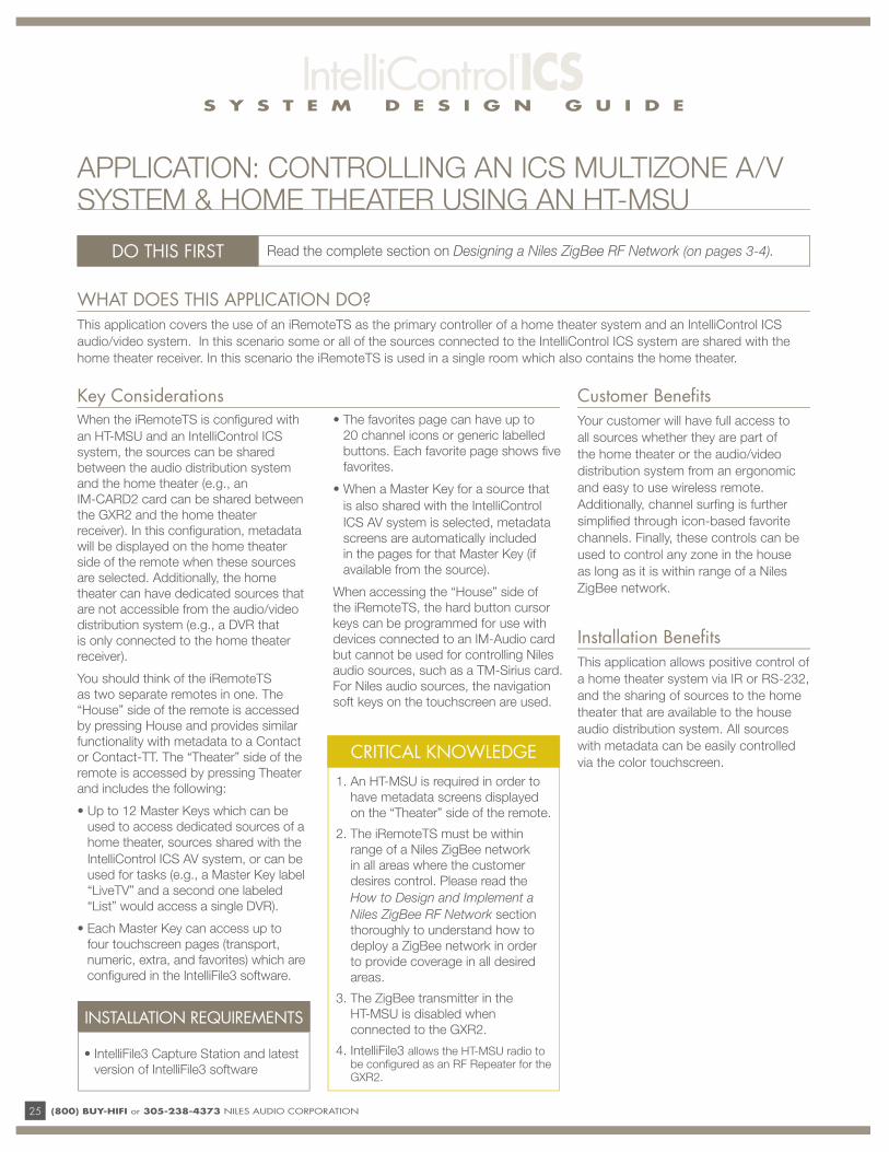
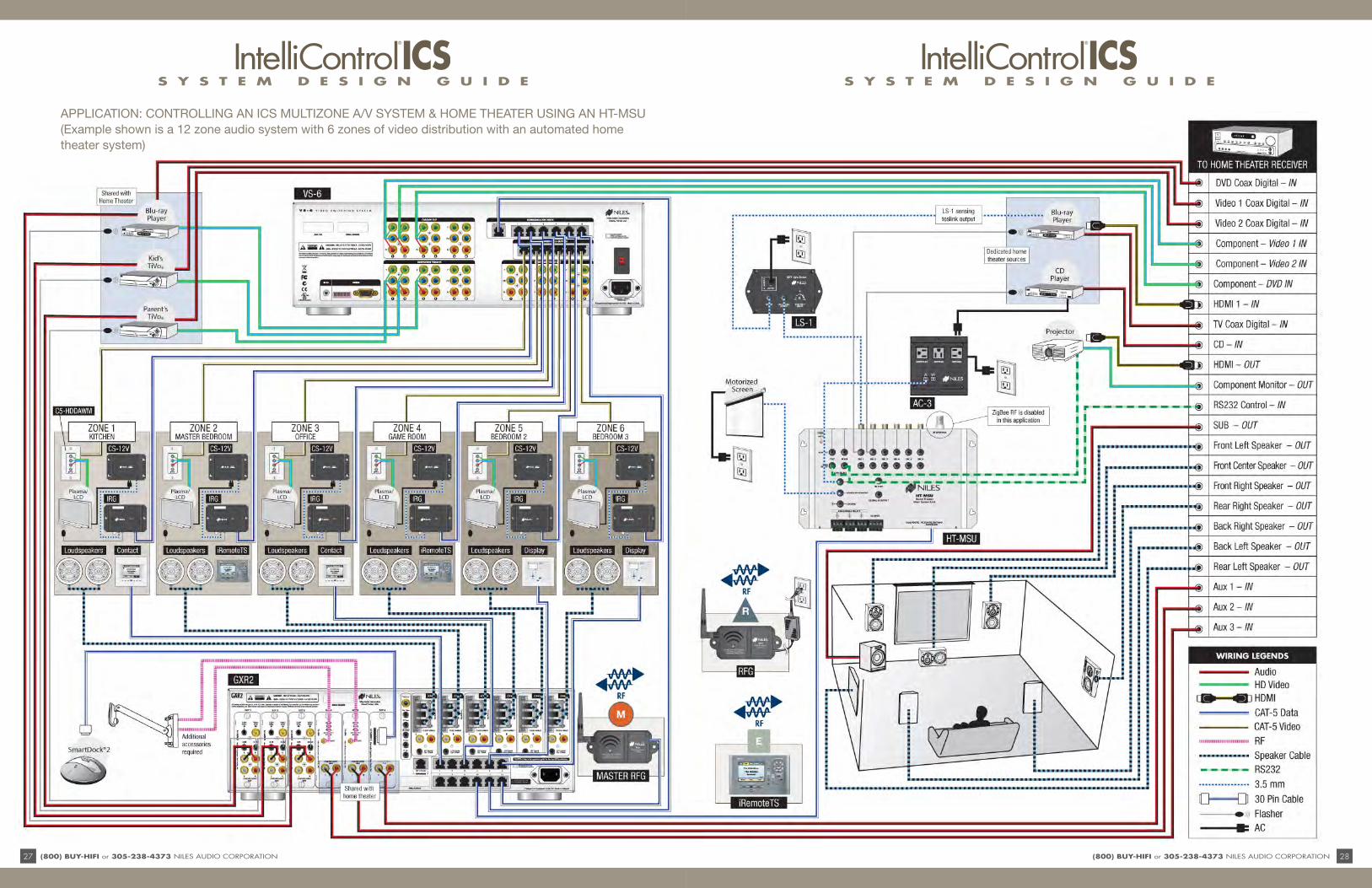
WHAT DOES THIS APPLICATION DO?This application covers the use of an iRemoteTS as the primary controller of a home theater system and an IntelliControl ICS
audio/video system. In this scenario some or all of the sources connected to the IntelliControl ICS system are shared with the
home theater receiver. In this scenario the iRemoteTS is used in a single room which also contains the home theater.
DO THIS FIRST Read the complete section on Designing a Niles ZigBee RF Network (on pages 3-4).
When the iRemoteTS is confi gured with
an HT-MSU and an IntelliControl ICS
system, the sources can be shared
between the audio distribution system
and the home theater (e.g., an
IM-CARD2 card can be shared between
the GXR2 and the home theater
receiver). In this confi guration, metadata
will be displayed on the home theater
side of the remote when these sources
are selected. Additionally, the home
theater can have dedicated sources that
are not accessible from the audio/video
distribution system (e.g., a DVR that
is only connected to the home theater
receiver).
You should think of the iRemoteTS
as two separate remotes in one. The
“House” side of the remote is accessed
by pressing House and provides similar
functionality with metadata to a Contact
or Contact-TT. The “Theater” side of the
remote is accessed by pressing Theater
and includes the following:
• Up to 12 Master Keys which can be
used to access dedicated sources of a
home theater, sources shared with the
IntelliControl ICS AV system, or can be
used for tasks (e.g., a Master Key label
“LiveTV” and a second one labeled
“List” would access a single DVR).
• Each Master Key can access up to
four touchscreen pages (transport,
numeric, extra, and favorites) which are
confi gured in the IntelliFile3 software.
• The favorites page can have up to
20 channel icons or generic labelled
buttons. Each favorite page shows fi ve
favorites.
• When a Master Key for a source that
is also shared with the IntelliControl
ICS AV system is selected, metadata
screens are automatically included
in the pages for that Master Key (if
available from the source).
When accessing the “House” side of
the iRemoteTS, the hard button cursor
keys can be programmed for use with
devices connected to an IM-Audio card
but cannot be used for controlling Niles
audio sources, such as a TM-Sirius card.
For Niles audio sources, the navigation
soft keys on the touchscreen are used.
Key Considerations Customer Benefi tsYour customer will have full access to
all sources whether they are part of
the home theater or the audio/video
distribution system from an ergonomic
and easy to use wireless remote.
Additionally, channel surfi ng is further
simplifi ed through icon-based favorite
channels. Finally, these controls can be
used to control any zone in the house
as long as it is within range of a Niles
ZigBee network.
Installation Benefi tsThis application allows positive control of
a home theater system via IR or RS-232,
and the sharing of sources to the home
theater that are available to the house
audio distribution system. All sources
with metadata can be easily controlled
via the color touchscreen.
INSTALLATION REQUIREMENTS
• IntelliFile3 Capture Station and latest
version of IntelliFile3 software
CRITICAL KNOWLEDGE
1. An HT-MSU is required in order to
have metadata screens displayed
on the “Theater” side of the remote.
2. The iRemoteTS must be within
range of a Niles ZigBee network
in all areas where the customer
desires control. Please read the
How to Design and Implement a
Niles ZigBee RF Network section
thoroughly to understand how to
deploy a ZigBee network in order
to provide coverage in all desired
areas.
3. The ZigBee transmitter in the
HT-MSU is disabled when
connected to the GXR2.
4. IntelliFile3 allows the HT-MSU radio to be confi gured as an RF Repeater for the GXR2.
APPLICATION: CONTROLLING AN ICS MULTIZONE A/V SYSTEM & HOME THEATER USING AN HT-MSU

S Y S T E M D E S I G N G U I D E
(800) BUY-HIFI or 305-238-4373 NILES AUDIO CORPORATION 26
CABLE SCHEDULEShared source connections to Master GXR2, VS-6, and Home Theater Receiver
Room connections (needed for each area that accesses the audio/video sources)
QTY CABLE SIGNAL FROM TO QTY CABLE SIGNAL FROM TO
1 Stereo RCA Audio Parent's TiVoMaster GXR2/IM-AUDIO #1
1 Speaker AudioMaster GXR2/Zone
1 SpeakerSpeakers
1 Component Video Parent's TiVo VS-6/Input 1 1 CAT-5 NetworkMaster GXR2/
Network SwitchContact
1 Mono RCA Digital Audio Parent's TiVoHT Receiver/Video 2 Coax
Dig. In1 CAT-5 Video VS-6/Zone 1 C5-HDDAWM Balun
1 Flasher IR Master GXR2/IM-AUDIO #1 Parent's TiVo 1 Component VideoC5-HDDAWM
BalunPlasma TV
1 Stereo RCA Audio Kid's TiVoMaster GXR2/IM-AUDIO #2
1 3.5mm Sync CS-12V IRG
1 Component Video Kid's TiVo VS-6/Input #2 1 CAT-5 NetworkVS-6/Network
SwitchIRG
1 Mono RCA Digital Audio Kid's TiVoHT Receiver/Video 1 Coax
Dig. In1 Flasher IR IRG Plasma TV
1 Flasher IR Master GXR2/IM-AUDIO #2 Kid's TiVo ZigBee network connections
1 Stereo RCA Audio Blu-Ray Player (shared)Master GXR2/IM-AUDIO #3
1 CAT-5 NetworkMaster GXR2/
Network SwitchRFG (Master RF Base)
1 Component Video Blu-Ray Player (shared) VS-6/Input #3 112V Power
SupplyPower Wall AC Outlet RFG (RF Repeater Base)
1 Mono RCA Digital Audio Blu-Ray Player (shared)HT Receiver/DVD
Coax Dig. InHT-MSU connections
1 Flasher IR Master GXR2/IM-AUDIO #3Blu-Ray Player
(shared)1 CAT-5 Network HT-MSU/Expansion
Master GXR2/Network Switch
1 RG-6 RF Sat. Radio AntennaMaster GXR2/
TM-XM #11 3.5 mm 12V DC
HT-MSU/Src #1 Sync
LS-1 (sensing Toslink output on dedicated
Blu-Ray player
1 RG-6 RF Sat. Radio AntennaMaster GXR2/
TM-XM #21 Flasher IR
HT-MSU/Src #1 IR Out
Blu-Ray Player (dedicated)
1 30 pin Audio+Data SmartDock2Master GXR2/
IM-iCARD21 Flasher IR
HT-MSU/Src #2 IR Out
CD Player
1 CAT-5 NetworkMaster GXR2/
Network SwitchVS-6/Out to
Master GXR21 RS-232 Control
HT-MSU/TV RS-232 Out
Projector RS-232 Control In
1 Component Video VS-6/Cascade Out #1HT Receiver/Component Video 1 In
1 RS-232 ControlHT-MSU/Receiver
RS-232 OutHT Receiver RS-232
Control In
1 Component Video VS-6/Cascade Out #2HT Receiver/Component Video 2 In
1 3.5mm 12V DCHT-MSU/
Trigger #1 OutAC-3 (Switch outlet for
CD player)
1 Component Video VS-6/Cascade Out #3HT Receiver/Component
DVD In1 3.5mm 12V DC
HT-MSU/Trigger #2 Out
Projection Screen Trigger In
1 Stereo RCA Audio Master GXR2/TM-XM OutHT Receiver/
Aux 3 InOther Home Theater Receiver connections
1 Stereo RCA Audio Master GXR2/TM-XM OutHT Receiver/
Aux 2 In1 HDMI Video
HT Receiver/HDMI Out
Projector HDMI In
1 Stereo RCA AudioMaster GXR2/IM-iCARD2 Out
HT Receiver/Aux 1 In
1 Component VideoHT Receiver/
Component OutProjector Component In
Dedicated source connections to Home Theater Receiver 1 Mono RCA AudioHT Receiver/
Sub OutSubwoofer LFE In
QTY CABLE SIGNAL FROM TO 1 Speaker AudioHT Receiver/L/C/R/
SL/SR/RL/RRL/C/R/SL/SR/RL/RR
Speakers
1 HDMI VideoBlu-Ray Player
(dedicated)HT Receiver/
HDMI 1 InRoom connections (needed for each area that accesses audio sources only)
1 Mono RCA Digital AudioBlu-Ray Player
(dedicated)HT Receiver/TV
Coax Dig. In1 Speaker Audio
Master GXR2/Zone 1 Speaker
Speakers
1 Mono RCA Digital Audio CD PlayerHT Receiver/CD
Coax Dig. In1 CAT-5 Network
Master GXR2/Network Switch
Contact
SEE NEXT PAGE FOR DIAGRAM
s y s t e m d e s i g n g u i d e
27 (800) Buy-HiFi or 305-238-4373 NILES AUDIO CORPORATION
s y s t e m d e s i g n g u i d e
(800) Buy-HiFi or 305-238-4373 NILES AUDIO CORPORATION 28
APPLICATION: CONTrOLLINg AN ICS MULTIZONE A/V SYSTEM & HOME THEATEr USINg AN HT-MSU (Example shown is a 12 zone audio system with 6 zones of video distribution with an automated home theater system)
S Y S T E M D E S I G N G U I D E
29 (800) BUY-HIFI or 305-238-4373 NILES AUDIO CORPORATION
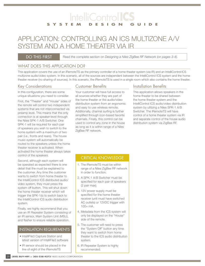
WHAT DOES THIS APPLICATION DO?This application covers the use of an iRemoteTS as the primary controller of a home theater system (via IR) and an IntelliControl ICS
multizone audio/video system. In this scenario, all of the sources are independent between the IntelliControl ICS system and the home
theater receiver (no sharing of sources). In this scenario, the iRemoteTS is used in a single room which also contains the home theater.
DO THIS FIRST Read the complete section on Designing a Niles ZigBee RF Network (on pages 3-4).
CRITICAL KNOWLEDGE
1. The iRemoteTS must be within
range of a Niles ZigBee RF network
in order to function.
2. A SPK-1 A/B Switcher must be
specifi ed for each pair of speakers
(2 pair max).
3. 12V power supply must be
specifi ed for the home theater
receiver (unit must have switched
AC outlets) or 12VDC trigger with
100+ mA.
4. Metadata from the ICS system will
only be displayed on the “House”
side of the remote.
5. The customer will need to press
the “System Off” button any time
they want to switch from home
theater to the ICS audio distribution
system.
6. IR Repeater System is highly
recommended.
INSTALLATION REQUIREMENTS
• IntelliFile3 Capture Station and
latest version of IntelliFile3 software
• IR sensor should be placed in the
line of sight of the iRemoteTS
Key ConsiderationsIn this confi guration, there are some
unique situations you need to consider.
First, the “Theater” and “House” sides of
the remote will control two independent
systems that are not interconnected via
preamp level. This means that the only
connection is at speaker-level through
the Niles SPK-1 A/B Switcher. One
SPK-1 will be required for each pair
of speakers you wish to switch to the
home system with a maximum of two
pair (i.e., fronts and rears). The house
music system will automatically be
routed to the speakers unless the home
theater receiver is activated. When
activated the home theater always takes
control of the speakers.
Second, although each system will
be operated as expected there is one
detail that the must be explained to
the customer. Any time the customer
wants to switch from home theater to
the IntelliControl ICS distributed audio/
video system, they must press the
system off button. This will shut down
the home theater receiver which will
trigger the SPK-1(s) to switch back to
the IntelliControl ICS audio distribution
system.
Finally, we highly recommend that you
use an IR Repeater System consisting of
an IR sensor, Main System Unit (MSU),
and fl asher to ensure reliable operation.
Customer Benefi tsYour customer will have full access to
all sources whether they are part of
the home theater or the audio/video
distribution system from an ergonomic
and easy to use wireless remote.
Additionally, channel surfi ng is further
simplifi ed through icon-based favorite
channels. Finally, this control can be
used to control any zone in the house
as long as it is within range of a Niles
ZigBee RF network.
Installation Benefi tsThis application allows speakers in the
home theater to be shared between
the home theater system and the
IntelliControl ICS audio/video distribution
system by utilizing a Niles SPK-1 A/B
Switcher. The iRemoteTS will have
control of a home theater system via IR
and separate control of the house audio
distribution system via ZigBee RF.
APPLICATION: CONTROLLING AN ICS MULTIZONE A/V SYSTEM AND A HOME THEATER VIA IR
S Y S T E M D E S I G N G U I D E
(800) BUY-HIFI or 305-238-4373 NILES AUDIO CORPORATION 30
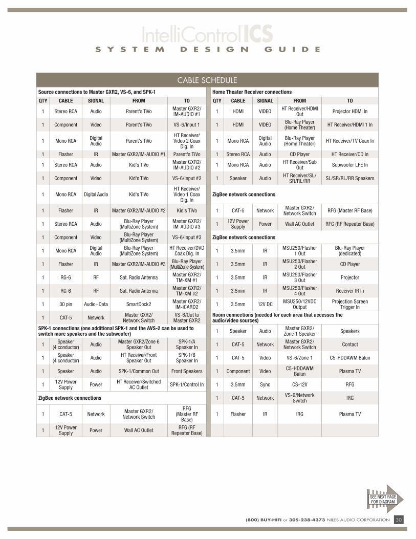
CABLE SCHEDULE
Source connections to Master GXR2, VS-6, and SPK-1 Home Theater Receiver connections
QTY CABLE SIGNAL FROM TO QTY CABLE SIGNAL FROM TO
1 Stereo RCA Audio Parent's TiVoMaster GXR2/IM-AUDIO #1
1 HDMI VIDEOHT Receiver/HDMI
OutProjector HDMI In
1 Component Video Parent's TiVo VS-6/Input 1 1 HDMI VIDEOBlu-Ray Player (Home Theater)
HT Receiver/HDMI 1 In
1 Mono RCADigital Audio
Parent's TiVoHT Receiver/Video 2 Coax
Dig. In1 Mono RCA
Digital Audio
Blu-Ray Player (Home Theater)
HT Receiver/TV Coax In
1 Flasher IR Master GXR2/IM-AUDIO #1 Parent's TiVo 1 Stereo RCA Audio CD Player HT Receiver/CD In
1 Stereo RCA Audio Kid's TiVoMaster GXR2/IM-AUDIO #2
1 Mono RCA AudioHT Receiver/Sub
OutSubwoofer LFE In
1 Component Video Kid's TiVo VS-6/Input #2 1 Speaker AudioHT Receiver/SL/
SR/RL/RRSL/SR/RL/RR Speakers
1 Mono RCA Digital Audio Kid's TiVoHT Receiver/Video 1 Coax
Dig. InZigBee network connections
1 Flasher IR Master GXR2/IM-AUDIO #2 Kid's TiVo 1 CAT-5 NetworkMaster GXR2/
Network SwitchRFG (Master RF Base)
1 Stereo RCA AudioBlu-Ray Player
(MultiZone System)Master GXR2/IM-AUDIO #3
112V Power
SupplyPower Wall AC Outlet RFG (RF Repeater Base)
1 Component VideoBlu-Ray Player
(MultiZone System)VS-6/Input #3 ZigBee network connections
1 Mono RCADigital Audio
Blu-Ray Player (MultiZone System)
HT Receiver/DVD Coax Dig. In
1 3.5mm IRMSU250/Flasher
1 OutBlu-Ray Player
(dedicated)
1 Flasher IR Master GXR2/IM-AUDIO #3Blu-Ray Player
(MultiZone System)1 3.5mm IR
MSU250/Flasher 2 Out
CD Player
1 RG-6 RF Sat. Radio AntennaMaster GXR2/
TM-XM #11 3.5mm IR
MSU250/Flasher 3 Out
Projector
1 RG-6 RF Sat. Radio AntennaMaster GXR2/
TM-XM #21 3.5mm IR
MSU250/Flasher 4 Out
Receiver IR In
1 30 pin Audio+Data SmartDock2Master GXR2/
IM-iCARD21 3.5mm 12V DC
MSU250/12VDC Output
Projection Screen Trigger In
1 CAT-5 NetworkMaster GXR2/
Network SwitchVS-6/Out to
Master GXR2Room connections (needed for each area that accesses the audio/video sources)
SPK-1 connections (one additional SPK-1 and the AVS-2 can be used to switch more speakers and the subwoofer)
1 Speaker AudioMaster GXR2/
Zone 1 SpeakerSpeakers
1Speaker
(4 conductor)Audio
Master GXR2/Zone 6 Speaker Out
SPK-1/A Speaker In
1 CAT-5 NetworkMaster GXR2/
Network SwitchContact
1Speaker
(4 conductor)Audio
HT Receiver/Front Speaker Out
SPK-1/B Speaker In
1 CAT-5 Video VS-6/Zone 1 C5-HDDAWM Balun
1 Speaker Audio SPK-1/Common Out Front Speakers 1 Component VideoC5-HDDAWM
BalunPlasma TV
112V Power
SupplyPower
HT Receiver/Switched AC Outlet
SPK-1/Control In 1 3.5mm Sync CS-12V RFG
ZigBee network connections 1 CAT-5 NetworkVS-6/Network
SwitchIRG
1 CAT-5 NetworkMaster GXR2/
Network Switch
RFG (Master RF
Base)1 Flasher IR IRG Plasma TV
112V Power
SupplyPower Wall AC Outlet
RFG (RF Repeater Base)
SEE NEXT PAGE FOR DIAGRAM

s y s t e m d e s i g n g u i d e
31 (800) Buy-HiFi or 305-238-4373 NILES AUDIO CORPORATION
s y s t e m d e s i g n g u i d e
(800) Buy-HiFi or 305-238-4373 NILES AUDIO CORPORATION 32
APPLICATION: CONTrOLLINg AN ICS MULTIZONE A/V SYSTEM ANd A HOME THEATEr VIA Ir(Example shown is 6 zone audio system with 6 zones of video distribution)
S Y S T E M D E S I G N G U I D E
33 (800) BUY-HIFI or 305-238-4373 NILES AUDIO CORPORATION
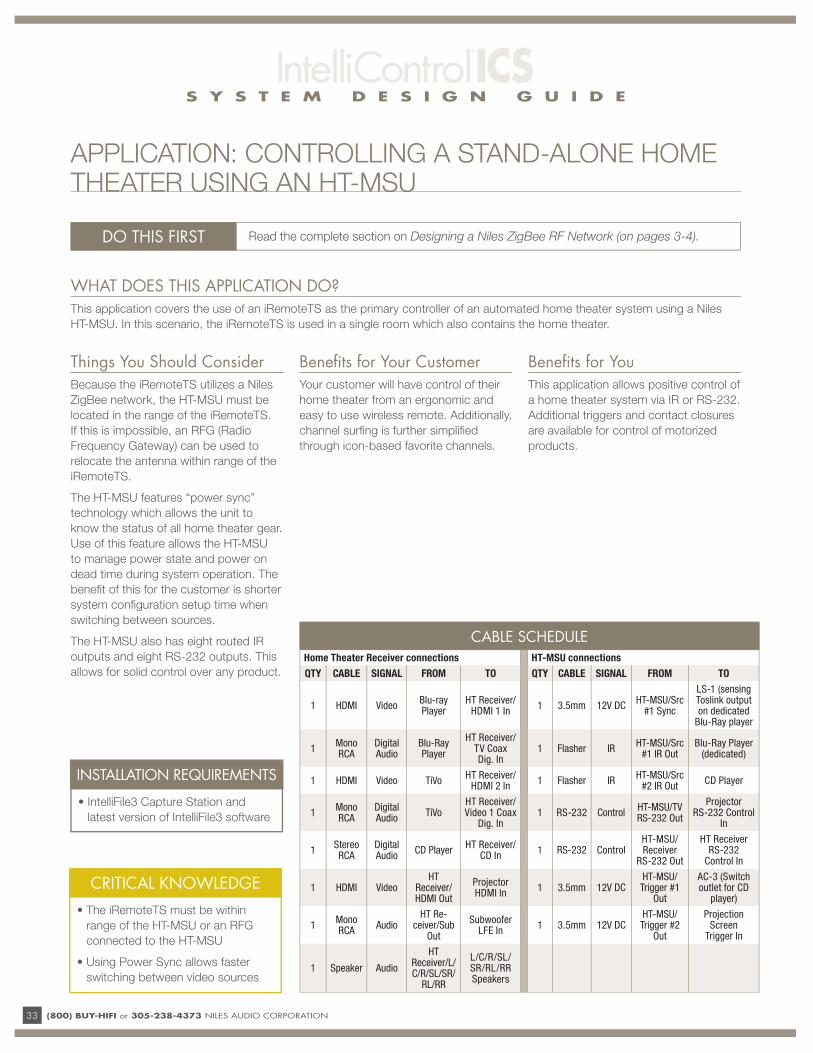
WHAT DOES THIS APPLICATION DO?This application covers the use of an iRemoteTS as the primary controller of an automated home theater system using a Niles
HT-MSU. In this scenario, the iRemoteTS is used in a single room which also contains the home theater.
DO THIS FIRST Read the complete section on Designing a Niles ZigBee RF Network (on pages 3-4).
INSTALLATION REQUIREMENTS
• IntelliFile3 Capture Station and
latest version of IntelliFile3 software
Things You Should ConsiderBecause the iRemoteTS utilizes a Niles
ZigBee network, the HT-MSU must be
located in the range of the iRemoteTS.
If this is impossible, an RFG (Radio
Frequency Gateway) can be used to
relocate the antenna within range of the
iRemoteTS.
The HT-MSU features “power sync”
technology which allows the unit to
know the status of all home theater gear.
Use of this feature allows the HT-MSU
to manage power state and power on
dead time during system operation. The
benefi t of this for the customer is shorter
system confi guration setup time when
switching between sources.
The HT-MSU also has eight routed IR
outputs and eight RS-232 outputs. This
allows for solid control over any product.
Benefi ts for Your CustomerYour customer will have control of their
home theater from an ergonomic and
easy to use wireless remote. Additionally,
channel surfi ng is further simplifi ed
through icon-based favorite channels.
Benefi ts for YouThis application allows positive control of
a home theater system via IR or RS-232.
Additional triggers and contact closures
are available for control of motorized
products.
APPLICATION: CONTROLLING A STAND-ALONE HOME THEATER USING AN HT-MSU
CABLE SCHEDULEHome Theater Receiver connections HT-MSU connections
QTY CABLE SIGNAL FROM TO QTY CABLE SIGNAL FROM TO
1 HDMI VideoBlu-ray Player
HT Receiver/HDMI 1 In
1 3.5mm 12V DCHT-MSU/Src
#1 Sync
LS-1 (sensing Toslink output on dedicated
Blu-Ray player
1Mono RCA
Digital Audio
Blu-Ray Player
HT Receiver/TV Coax Dig. In
1 Flasher IRHT-MSU/Src
#1 IR OutBlu-Ray Player
(dedicated)
1 HDMI Video TiVoHT Receiver/
HDMI 2 In1 Flasher IR
HT-MSU/Src #2 IR Out
CD Player
1Mono RCA
Digital Audio
TiVoHT Receiver/Video 1 Coax
Dig. In1 RS-232 Control
HT-MSU/TV RS-232 Out
Projector RS-232 Control
In
1Stereo RCA
Digital Audio
CD PlayerHT Receiver/
CD In1 RS-232 Control
HT-MSU/Receiver
RS-232 Out
HT Receiver RS-232
Control In
1 HDMI VideoHT
Receiver/HDMI Out
Projector HDMI In
1 3.5mm 12V DCHT-MSU/Trigger #1
Out
AC-3 (Switch outlet for CD
player)
1Mono RCA
AudioHT Re-
ceiver/Sub Out
Subwoofer LFE In
1 3.5mm 12V DCHT-MSU/Trigger #2
Out
Projection Screen
Trigger In
1 Speaker Audio
HT Receiver/L/C/R/SL/SR/
RL/RR
L/C/R/SL/SR/RL/RR Speakers
CRITICAL KNOWLEDGE
• The iRemoteTS must be within
range of the HT-MSU or an RFG
connected to the HT-MSU
• Using Power Sync allows faster
switching between video sources

S Y S T E M D E S I G N G U I D E
(800) BUY-HIFI or 305-238-4373 NILES AUDIO CORPORATION 34
iREMOTE TS AS A CONTROL DEVICE FOR AN AUTOMATED HOME THEATER USING AN HT-MSU
S Y S T E M D E S I G N G U I D E
35 (800) BUY-HIFI or 305-238-4373 NILES AUDIO CORPORATION
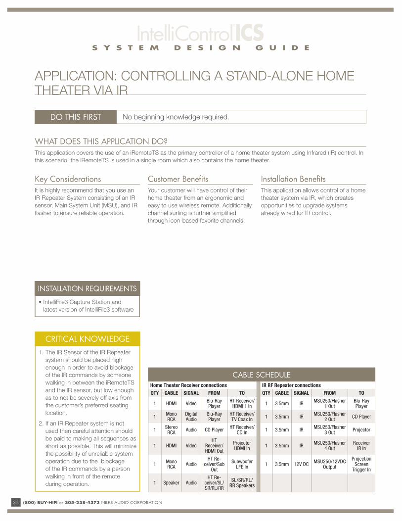
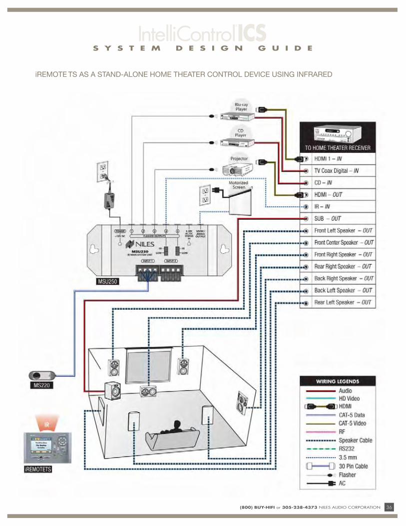
WHAT DOES THIS APPLICATION DO?This application covers the use of an iRemoteTS as the primary controller of a home theater system using Infrared (IR) control. In
this scenario, the iRemoteTS is used in a single room which also contains the home theater.
DO THIS FIRST No beginning knowledge required.
CRITICAL KNOWLEDGE
1. The IR Sensor of the IR Repeater
system should be placed high
enough in order to avoid blockage
of the IR commands by someone
walking in between the iRemoteTS
and the IR sensor, but low enough
as to not be severely off axis from
the customer’s preferred seating
location.
2. If an IR Repeater system is not
used then careful attention should
be paid to making all sequences as
short as possible. This will minimize
the possibility of unreliable system
operation due to the blockage
of the IR commands by a person
walking in front of the remote
during operation.
Key ConsiderationsIt is highly recommend that you use an
IR Repeater System consisting of an IR
sensor, Main System Unit (MSU), and IR
fl asher to ensure reliable operation.
Customer Benefi tsYour customer will have control of their
home theater from an ergonomic and
easy to use wireless remote. Additionally
channel surfi ng is further simplifi ed
through icon-based favorite channels.
Installation Benefi tsThis application allows control of a home
theater system via IR, which creates
opportunities to upgrade systems
already wired for IR control.
APPLICATION: CONTROLLING A STAND-ALONE HOME THEATER VIA IR
CABLE SCHEDULEHome Theater Receiver connections IR RF Repeater connections
QTY CABLE SIGNAL FROM TO QTY CABLE SIGNAL FROM TO
1 HDMI VideoBlu-Ray Player
HT Receiver/HDMI 1 In
1 3.5mm IRMSU250/Flasher
1 OutBlu-Ray Player
1Mono RCA
Digital Audio
Blu-Ray Player
HT Receiver/TV Coax In
1 3.5mm IRMSU250/Flasher
2 OutCD Player
1Stereo RCA
Audio CD PlayerHT Receiver/
CD In1 3.5mm IR
MSU250/Flasher 3 Out
Projector
1 HDMI VideoHT
Receiver/HDMI Out
Projector HDMI In
1 3.5mm IRMSU250/Flasher
4 OutReceiver
IR In
1Mono RCA
AudioHT Re-
ceiver/Sub Out
Subwoofer LFE In
1 3.5mm 12V DCMSU250/12VDC
Output
Projection Screen
Trigger In
1 Speaker AudioHT Re-
ceiver/SL/SR/RL/RR
SL/SR/RL/RR Speakers
INSTALLATION REQUIREMENTS
• IntelliFile3 Capture Station and
latest version of IntelliFile3 software
S Y S T E M D E S I G N G U I D E
(800) BUY-HIFI or 305-238-4373 NILES AUDIO CORPORATION 36
iREMOTE TS AS A STAND-ALONE HOME THEATER CONTROL DEVICE USING INFRARED

S Y S T E M D E S I G N G U I D E
37 (800) BUY-HIFI or 305-238-4373 NILES AUDIO CORPORATION
INTELLIFILE3 PROGRAMMING STEPS
UPDATE PROGRAMMING SOFTWARE
Always update your software to the latest version of IntelliFile3 before installing any products. IntelliFile3 can be
downloaded at www.intellicontrol.com/techsupport
UPDATE FIRMWARE
All units must be hard-wire connected to the GXR2 during fi rmware update. Always perform a fi rmware update on all
previously installed IntelliControl ICS products before adding new products. Follow this sequence:
1. Upload previous programming from the GXR2
2. Firmware update the current system
3. Unplug the GXR2
4. Connect the new products to the GXR2
5. Reconnect the power to the GXR2
6. Perform fi rmware update on the new products, including the HT-MSU and the iRemoteTS
7. Upload previous programming from the GXR2 again
PROGRAMMING SEQUENCE
ALL UNITS MUST BE HARD-WIRE CONNECTED TO THE GXR2 DURING PROGRAMMING:
1. Perform MultiZone programming fi rst
2. Then perform the home theater
programming and upload to the HT-MSU
3. Upload the home theater programming
to the iRemoteTS
4. Take and position all wireless devices to
their fi nal position in the house
5. Perform a “Reset Net” from the installer
screen of one of the End-Points
(iRemote, iRemoteTS or wireless keypad)
(800) BUY-HIFI or 305-238-4373 NILES AUDIO CORPORATION 38
WARRANTYAll Niles products are manufactured with reliability in mind and backed by factory warranties against defects in materials or workmanship. For details,
see warranty statement included with each product.
We are eager to hear your product suggestions.
Please e-mail your suggestions to: [email protected]
Niles strives to constantly improve our products, all specifications may change without notice.
CUSTOMER SERVICE - TECHNICAL SUPPORT:
ADDITIONAL INFORMATION
©2010 Niles Audio Corporation 12331 S.W. 130 Street, Miami, FL 33186 Tel: 800.289.4434 or 305.238.4373 – www.nilesaudio.com – All rights reserved. Niles, the Niles logos, IntelliControl, SmartDock, IntelliFile and iREMOTE are registered trademarks of Niles Audio Corporation. All other trademarks are the property of their respective owners. Niles reserves the right to change specifi cations and descriptions without notice. The technical and other information contained herein is not intended to set forth all technical and other specifi cations. LT00293B
BY PHONE (IN USA OR CANADA)
1-800-BUY-HIFI (289-4434)
BY PHONE (OUTSIDE USA)
1-305-238-4373
CUSTOMER SERVICE HOURS
8:00 AM to 5:30 PM ET
TECHNICAL SUPPORT HOURS
8:00 AM to 7:00 PM ET
ON THE WEB
www.nilesaudio.com
EMAIL TECHNICAL SUPPORT
EMAIL FOR PRODUCT SUGGESTIONS
Niles Audio Corporation
12331 SW 130th Street, Miami FL 33186 Tel: 800-BUY-HIFI or 305-238-4373 – Fax: 305.238.0185 – www.nilesaudio.com