Nikhilesh Mohanty ECE-11203 3 rd Yr. Regional Telecom Training Centre.
30
Presentation on GSM Nikhilesh Mohanty ECE-11203 3 rd Yr. Regional Telecom Training Centre
-
Upload
laurel-samantha-holmes -
Category
Documents
-
view
231 -
download
3
Transcript of Nikhilesh Mohanty ECE-11203 3 rd Yr. Regional Telecom Training Centre.

Presentation on GSM
Nikhilesh MohantyECE-112033rd Yr.
Regional Telecom Training Centre

Contents
• GSM-Introduction
• Architecture
• Technical Specifications
• Channels
• Security
• Characteristics and features
• Applications

What is GSM ?
Earlier called as Groupe Special Mobile(1982) in Europe.
Global System for Mobile Communication(GSM) is a second generation(2G) cellular standard developed to cater voice services and data delivery using digital modulation.

GSM: History• Developed by Group Special Mobile (founded 1982) which was an
initiative of CEPT ( Conference of European Post and Telecommunication )
• Aim : to replace the incompatible analog system
• Presently the responsibility of GSM standardization resides with special mobile group under ETSI ( European telecommunication Standards Institute )
• Full set of specifications phase-I became available in 1990
• Under ETSI, GSM is named as “ Global System for Mobile communication “
• Today many providers all over the world use GSM (more than 135
countries in Asia, Africa, Europe, Australia, America)
• More than 1300 million subscribers in world and 45 million subscriber in India.

GSM Services
Tele-services
Bearer or Data Services
Supplementary services

Tele Services
Telecommunication services that enable voice communication
via mobile phones
Offered services
- Mobile telephony
- Emergency calling

Bearer Services
Include various data services for information transfer between GSM and other networks like PSTN, ISDN etc at rates from 300 to 9600 bps
Short Message Service (SMS) up to 160 character alphanumeric data transmission to/from the mobile terminal
Unified Messaging Services(UMS)
Group 3 fax - Voice mailbox - Electronic mail

Supplementary Services
Call related services :
• Call Waiting- Notification of an incoming call while on the handset
• Call Hold- Put a caller on hold to take another call
• Call Barring- All calls, outgoing calls, or incoming calls
• Call Forwarding- Calls can be sent to various numbers defined by the user
• Multi Party Call Conferencing - Link multiple calls together
• CLIP – Caller line identification presentation
• CLIR – Caller line identification restriction
• CUG – Closed user group

BTS
MSC VLR
HLR
PSTNISDN
DataNetworks
(
Air interface
OMC
BTS
BTS
VLR
BSCBSC
A Interface
A-bis interface
UM Interface
GSM System Architecture
GMSC
BTS
BTS
BSC
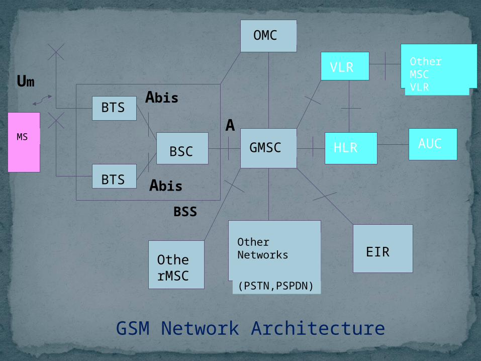
GSM Network Architecture
HLR
OMC
VLR
BSS
AUC
Other MSC VLR
Other Networks
(PSTN,PSPDN)
EIROtherMSC
MSA
Abis
Abis
Um

GSM System Architecture-I
Mobile Station (MS)Mobile Equipment (ME)Subscriber Identity Module (SIM)
Base Station Subsystem (BSS)Base Transceiver Station (BTS)Base Station Controller (BSC)
Network Switching Subsystem(NSS)Mobile Switching Center (MSC)Home Location Register (HLR)Visitor Location Register (VLR)Authentication Center (AUC)Equipment Identity Register (EIR)

System Architecture
Mobile Station (MS)
The Mobile Station is made up of two entities:
1. Mobile Equipment (ME)
2. Subscriber Identity Module (SIM)

System ArchitectureMobile Station (MS)
Mobile Equipment
Portable, vehicle mounted, hand held device
Uniquely identified by an IMEI
Voice and data transmission
Monitoring power and signal quality of surrounding cells for optimum handover
Power level : 0.8W – 20 W
160 character long SMS.

System ArchitectureMobile Station (MS) contd.Subscriber Identity Module (SIM)
SIM card contains the (IMSI).
Allows user to send and receive calls and receive other subscribed services.
Encoded network identification details - Key Ki, Kc and A3, A5 and A8 algorithms
Protected by a password or PIN
Can be moved from phone to phone – contains key information to activate the phone

System ArchitectureBase Station Subsystem (BSS)
Base Station Subsystem is composed of two parts that communicate across the standardized Abis interface allowing operation between components made by different suppliers
1.Base Transceiver Station (BTS)
2.Base Station Controller (BSC)

System Architecture Base Station Subsystem (BSS) Base Transceiver Station (BTS):
Encodes, encrypts, multiplexes, modulates and feeds the RF signals to the antenna.
Frequency hopping
Transcoding and rate adaption Functionality, Time and frequency synchronization signals transmission.
Communicates with Mobile station and BSC
Consists of Transceivers (TRX) units

System Architecture Base Station Subsystem (BSS)
Base Station Controller (BSC)
Manages Radio resources for BTS
Assigns Frequency and time slots for all MS’s in its area
Handles call set up
Transcoding and rate adaptation functionality
Handover for each MS
Radio Power control
It communicates with MSC and BTS

System Architecture Network Switching Subsystem(NSS)Mobile Switching Center (MSC)
Heart of the network
Manages communication between GSM and other networks
Call setup function and basic switching
Call routing
Billing information and collection
Mobility management- Registration- Location Updating- Inter BSS and inter MSC call handoff
MSC does gateway function while its customer roams to other network by using HLR/VLR.

System Architecture Network Switching Subsystem
Home Location Registers (HLR)- permanent database about mobile subscribers in a large service
area(generally one per GSM network operator)
- database contains IMSI,MSISDN,prepaid/postpaid,roaming restrictions,supplementary services.
-Reference store for subscriber’s parameters, numbers, authentication & Encryption values.
-Current subscriber status and associated VLR.
-Both VLR and HLR can be implemented in the same equipment in an MSC.
-one PLMN may contain one or several HLR.

Visitor Location Registers (VLR)
-Temporary database which updates whenever new MS enters its area, by HLR database
-Controls those mobiles roaming in its area
-Reduces number of queries to HLR -Database contains IMSI, TMSI, MSISDN, MSRN, Location area & authentication key
-It controls those mobiles roaming in its area.
-VLR reduces the number of queries to HLR, One VLR may be in charge of one or more LA.
-VLR is updated by HLR on entry of MS its area.
-VLR assigns TMSI which keeps on changing.
-IMSI detach and attach operation

System Architecture Network Switching Subsystem
Authentication Center (AUC)
- Protects against intruders in air interface- Maintains authentication keys and algorithms and
provides security triplets ( RAND,SRES,Kc)- Generally associated with HLR
Equipment Identity Register (EIR)
- Database that is used to track handsets using the IMEI (International Mobile Equipment Identity)
- Made up of three sub-classes: The White List, The Black List and the Gray List
- Only one EIR per PLMN

Operation subsystem
The OSS (Operation Subsystem) enables centralized operation, management, and maintenance of all GSM subsystemsComponents
Authentication Center (AUC)generates user specific authentication parameters on request of a VLR authentication parameters used for authentication of mobile terminals and encryption of user data on the air interface within the GSM system
Equipment Identity Register (EIR)registers GSM mobile stations and user rightsstolen or malfunctioning mobile stations can be locked and sometimes even localized
Operation and Maintenance Center (OMC)different control capabilities for the radio subsystem and the network subsystem

MSC Hand over

Many Types of Logical Channels
• Control channels– broadcast control channel (BCCH)
• from base station, announces cell identifier, synchronization, hopping sequence
– common control channels (CCCH)• random access channel (RACH):
MSs for initial access, slotted Aloha• access grant channel (AGCH):
BTS informs an MS its allocation• paging channel (PCH): base
transceiver station (BTS) pages a mobile host (MS)
– dedicated control channels• standalone dedicated control
channel (SDCCH): signaling and short message between MS and an MS
• Traffic channels (TCH)- between n/w and MS
• speech & data
Example: call setup from an MS
BTSMS
RACH (request signaling channel)
AGCH (assign signaling channel)
SDCCH (request call setup)
SDCCH (assign TCH)
SDCCH message exchange
Communication

GSM Specifications-1
RF Spectrum
GSM 900 Mobile to BTS (uplink): 890-915 MHz BTS to Mobile(downlink): 935-960 MHz Bandwidth : 2* 25 MHz
GSM 1800 Mobile to BTS (uplink): 1710-1785 MHz BTS to Mobile(downlink) 1805-1880 MHz Bandwidth : 2* 75 MHz

GSM Specification-II
Carrier Separation : 200 KHzDuplex Distance : 45 MHzNo. of RF carriers : 124
Access Method : TDMA/FDMAModulation Method : GMSKModulation data rate : 270.833 Kbps

GSM Operation
Speech decoding
Channel decoding
De-interleaving
Burst Formatting
De-ciphering
DemodulationModulation
Ciphering
Burst Formatting
Interleaving
Channel Coding
Speech coding
Radio Interface
Speech(Hi…) Speech(Hi…)
13 Kbps
22.8 Kbps
22.8 Kbps
33.6 Kbps
33.6 Kbps
270.83 Kbps
Caller Receiver

Security in GSM
On air interface, GSM uses encryption and TMSI instead of IMSI.
SIM is provided 4-8 digit PIN to validate the ownership of SIM
3 algorithms are specified :- A3 algorithm for authentication- A5 algorithm for encryption- A8 algorithm for key generation

Characteristics of GSM StandardFully digital system using 900,1800 MHz frequency band.
TDMA over radio carriers(200 KHz carrier spacing.
8 full rate or 16 half rate TDMA channels per carrier.
User/terminal authentication for fraud control.
Encryption of speech and data transmission over the radio path.
Full international roaming capability.
Low speed data services (up to 9.6 Kb/s).
Compatibility with ISDN.
Support of Short Message Service (SMS).

GSM Applications
Mobile telephony
GSM-R
Telemetry System - Fleet management - Automatic meter reading - Toll Collection - Remote control and fault reporting of stolen sets
Value Added Services