Nickel-Plated Brass Push-In Fittings Series 6000
28
3 PUSH-IN FITTINGS Push-In Fittings 1 NORTH AMERICAN FITTINGS & FLOW CONTROL VALVE CATALOG > July 2019 The company reserves the right to vary models and dimensions without notice. These products are designed for industrial applications and are not suitable for sale to the general public. Minimum Torque Maximum Torque Thread Size N-m lb-ft N-m lb-ft M5 [10-32 UNF] 0.400 0.295 2.000 1.475 1/8 NPTF or BSP 2.000 1.475 10.000 7.376 1/4 NPTF or BSP 4.000 2.950 20.000 14.751 3/8 NPTF or BSP 5.000 3.688 20.000 14.751 1/2 NPTF or BSP 8.000 5.900 40.000 29.502 Nickel-Plated Brass Push-In Fittings Series 6000 Camozzi’s all metal fittings are 100% electrolytic nickel-plated brass. Full ID tube flow is always maintained for maximum Cv ratings and quick cycle times. “Push-in” and lock the tube quickly and effortlessly. Fittings also available in coated thread sealant, Loctite Vibra-Seal 516 (use “C” prefix in part code, see tables for available models). Connection and disconnection of the tube can be repeated several times and can be performed using one hand and without the use of tools. Tube Diameter OD : 1/8”, 5/32”, 1/4”, 5/16”, 3/8”, 1/2”, 3 , 4, 5 , 6 , 8 , 10 , 12 , 14 or 16 mm Thread Type : 10-32 UNF, 1/8”, 1/4”, 3/8”, 1/2”, 3/4” NPTF, BSP, Pro-Fit ® , or Sprint ® (Reusable PTFE/Teflon thread seal) Fitting with connecting tube GENERAL DATA Material Body and collet: nickel-plated brass, (UNI 5705 OT58) O-Ring: NBR (standard); Viton and EPDM available on request thread seal: PTFE - NBR - PA; Loctite Vibra-Seal 516 (red) Threads 10-32 UNF, 1/8”, 1/4”, 3/8”, 1/2” NPTF, Pro-Fit® M3 - M5 - M7 - G1/8 - G1/4 - G3/8 - G1/2 - G3/4 , Sprint® , GAS conical ISO 7 (BSPT), GAS cylindrical ISO 228 (BSP) *M5-M6 and other metric threads available on request Pressure min -0.9 bar - max 16 bar (28” Hg vacuum to 250 psi) (see tubing) Tube to connect Nylon 6, 11 or 12, polyethylene, PU, (Polyurethane recommended 90A durometer and above) Hytrel Polyester Tube Diameters OD Inch tubing: 1/8” - 5/32” - 1/4” - 5/16” - 3/8” - 1/2” Metric tubing: ø 3 - 4 - 5 -6 - 8 - 10 - 12 - 14 - 16 mm Fluid compressed air (for other types of fluid, contact our engineers) Temperature -20°C - 80°C , -4 F to 175 F (see data for tubing used) Micro: -10°C - 80°C (14 F to 175 F) (see data for tubing used) Pro-Fit ® and Sprint ® Torque Specifications
Transcript of Nickel-Plated Brass Push-In Fittings Series 6000

3
PUSH
-IN F
ITTI
NGS
Push-In Fittings1 NORTH AMERICAN FITTINGS & FLOW CONTROL VALVE CATALOG > July 2019
The company reserves the right to vary models and dimensions without notice.These products are designed for industrial applications and are not suitable for sale to the general public.
Minimum Torque Maximum Torque
Thread Size N-m lb-ft N-m lb-ft
M5 [10-32 UNF] 0.400 0.295 2.000 1.475
1/8 NPTF or BSP 2.000 1.475 10.000 7.376
1/4 NPTF or BSP 4.000 2.950 20.000 14.751
3/8 NPTF or BSP 5.000 3.688 20.000 14.751
1/2 NPTF or BSP 8.000 5.900 40.000 29.502
Nickel-Plated Brass Push-In Fittings Series 6000
Camozzi’s all metal fittings are 100% electrolytic nickel-plated brass. Full ID tube flow is always maintained for maximum Cv ratings and quick cycle times. “Push-in” and lock the tube quickly and effortlessly.
Fittings also available in coated thread sealant, Loctite Vibra-Seal 516 (use “C” prefix in part code, see tables for available models).
Connection and disconnection of the tube can be repeated several times and can be performed using one hand and without the use of tools.
Tube Diameter OD : 1/8”, 5/32”, 1/4”, 5/16”, 3/8”, 1/2”, 3 , 4, 5 , 6 , 8 , 10 , 12 , 14 or 16 mm Thread Type : 10-32 UNF, 1/8”, 1/4”, 3/8”, 1/2”, 3/4” NPTF, BSP, Pro-Fit®, or Sprint® (Reusable PTFE/Teflon thread seal)
Fitting with connecting tubeGENERAL DATAMaterial Body and collet: nickel-plated brass, (UNI 5705 OT58)
O-Ring: NBR (standard); Viton and EPDM available on request thread seal: PTFE - NBR - PA; Loctite Vibra-Seal 516 (red)
Threads 10-32 UNF, 1/8”, 1/4”, 3/8”, 1/2” NPTF, Pro-Fit®M3 - M5 - M7 - G1/8 - G1/4 - G3/8 - G1/2 - G3/4 , Sprint® , GAS conical ISO 7 (BSPT), GAS cylindrical ISO 228 (BSP) *M5-M6 and other metric threads available on request
Pressure min -0.9 bar - max 16 bar (28” Hg vacuum to 250 psi) (see tubing)Tube to connect Nylon 6, 11 or 12, polyethylene, PU, (Polyurethane recommended 90A durometer
and above) Hytrel PolyesterTube DiametersOD
Inch tubing: 1/8” - 5/32” - 1/4” - 5/16” - 3/8” - 1/2” Metric tubing: ø 3 - 4 - 5 -6 - 8 - 10 - 12 - 14 - 16 mm
Fluid compressed air (for other types of fluid, contact our engineers)Temperature -20°C - 80°C , -4 F to 175 F (see data for tubing used)
Micro: -10°C - 80°C (14 F to 175 F) (see data for tubing used)
Pro-Fit® and Sprint® Torque Specifications

4
PUSH
-IN F
ITTI
NGS
Push-In Fittings1 NORTH AMERICAN FITTINGS & FLOW CONTROL VALVE CATALOG > July 2019
The company reserves the right to vary models and dimensions without notice.These products are designed for industrial applications and are not suitable for sale to the general public.
Features
Collet• Nickel-Plated, All-metal Collet and Release ring• Collet design offers greater grip strength under higher
pressure or tubing tension• Collet release mechanism based on relaxed slope of grip
teeth, as opposed to disengaging “bite-rings” from partially cut tubes
• Removable Collet and tube o-rings
Body• All-Metal, Nickel-Plated body and Threads• Compact Brass bodies from Brass forgings• Standard Buna-N or Specialized O-ring choices for High-Temp,
Low-Temp, Special Fluids, Food-Grade compatibility• Broad Range of shapes and configurations• Crimp design on Swivels maintains Full ID Flow path • Swivels offer Mechanical crimping lock based on cold-forged
brass and not spin-swaged or “thinned” brass• Full ID Flow for Swivels and Straights, with high relief on
larger sizes• Internal Hex on Straight fittings
Pro-Fit® Thread Design• Low Profile Fit• Fast Installation• Perfect Reusable Seal
Benefits
Collet• Won’t break like plastic release rings and bodies; More Durable
design• Higher holding force, with easier release• Won’t scratch tubes like “bite-ring” designs• Less chance of micro-leakage and bubble-leaks over time due to
damaged tubing• Higher pressures actually offer greater grip-strength with high-
pressure Nylon tubing• OD Tube Size stamped on Collet face
Body• Resistant to UV exposure• Better resistance to stress-cracking, abrasion, solvents, detergents,
hydrocarbons and other fluid media• FDA/NSF approved materials, ( Including customized Nickel-
Plating and o-ring options) available on request• Simplified manifold circuits with broader variety of fitting
combinations and shapes to select• Lighter weight for End-of-Arm tooling & Robotic handling, • Compact design reduces overall dimensions for valve assemblies,
packaging applications and control cabinets• 12% Reduction in overall Body size, compared to previous Brass
line• Full ID Flow and high relief undercuts offers greatest flow without
restriction to circuit design flow calculations
Pro-Fit® Thread Design• Eliminates exposed threads and fits into tight spaces, making
them ideal for food processing and hygienic applications.• Eliminates the need for Teflon® tape or pipe dope. Shorter thread
length requires fewer turns to tighten.• The captured Teflon® sealing ring provides a dependable
and reusable shoulder seal without the risk of thread sealant contamination.
Collet
Body
Thread
O-Ring Seal
Standard NPTF & NPTF Coated Thread
Nickel-Plated Brass Push-In Fittings Series 6000
Collet
Body
Pro-Fit®
Thread
O-Ring Seal
Pro-Fit® Style NPTF Thread
Pro-Fit®
Sealing Ring

5
PUSH
-IN F
ITTI
NGS
Push-In Fittings1 NORTH AMERICAN FITTINGS & FLOW CONTROL VALVE CATALOG > July 2019
The company reserves the right to vary models and dimensions without notice.These products are designed for industrial applications and are not suitable for sale to the general public.
P6510
P6510
METRIC Tube FittingsDIMENSIONS (in mm)
Model A D C F G H L SW SW1 Weight (g)
S6510 4-1/8 4 G1/8 3.8 8.8 13.2 5.5 18 12 2.5 9
S6510 4-1/4 4 G1/4 5.5 8.8 15.2 7 19.5 14 2.5 15
S6510 5-1/8 5 G1/8 3.8 9.8 13.2 5.5 19 12 3 8
S6510 5-1/4 5 G1/4 5.5 9.8 15.2 7 20 14 3 14
S6510 6-1/8 6 G1/8 6 11.7 13.2 5.5 22 12 4 10
S6510 6-1/4 6 G1/4 5.5 11.7 15.2 7 21 14 4 14
S6510 6-3/8 6 G3/8 6.5 11.7 20.5 8 22.5 19 4 27
S6510 8-1/8 8 G1/8 7.5 13.7 15.2 5.5 25 14 5 13
S6510 8-1/4 8 G1/4 6.5 13.7 15.2 7 24 14 6 14
S6510 8-3/8 8 G3/8 6 13.7 20.5 8 23.5 19 6 25
S6510 8-1/2 8 G1/2 7.5 13.7 24.5 9 25 22 6 43
S6510 10-1/4 10 G1/4 8.3 15.4 18.5 7 28.5 17 7 23
S6510 10-3/8 10 G3/8 5.3 15.4 20.5 8 25.5 19 8 27
S6510 10-1/2 10 G1/2 4.8 16 24.5 9 25 22 8 39
S6510 12-1/4 12 G1/4 10.3 18.3 20.5 7 29.5 19 7 26
S6510 12-3/8 12 G3/8 9.3 18.3 20.5 8 28.5 19 9 30
S6510 12-1/2 12 G1/2 5.8 18.3 24.5 9 25 22 10 36
S6510 14-3/8 14 G3/8 10.3 20.5 24.5 8 30.5 22 9 42
S6510 14-1/2 14 G1/2 6.3 20.5 24.5 9 26.5 22 12 34
S6510 16-1/2 16 G1/2 9 23.5 26.5 9 32 24 - 42
S6510 16-3/4 16 G3/4 3.5 23.5 27.3 9 26.5 24 - 46
INCH Tube FittingsDIMENSIONS (in inches)
Model A OD
D NPTF
C F G H L SW SW1
P6510 02-02 1/8 1/8 0.177 0.346 0.551 0.197 0.728 0.472 0.098
P6510 02-04 1/8 1/4 0.256 0.346 0.630 0.256 0.807 0.551 0.098
P6510 53-02 5/32 1/8 0.177 0.346 0.551 0.197 0.728 0.472 0.098
P6510 53-04 5/32 1/4 0.256 0.346 0.630 0.256 0.807 0.551 0.098
P6510 04-02 1/4 1/8 0.189 0.461 0.551 0.197 0.827 0.472 0.157
P6510 04-04 1/4 1/4 0.228 0.461 0.630 0.256 0.866 0.551 0.157
P6510 04-06 1/4 3/8 0.268 0.461 0.866 0.295 0.906 0.748 0.157
P6510 05-02 5/16 1/8 0.276 0.539 0.630 0.197 0.965 0.551 0.197
P6510 05-04 5/16 1/4 0.276 0.539 0.630 0.256 0.965 0.551 0.236
P6510 05-06 5/16 3/8 0.256 0.539 0.866 0.295 0.945 0.748 0.236
P6510 06-02 3/8 1/8 0.315 0.606 0.776 0.197 1.102 0.669 0.197
P6510 06-04 3/8 1/4 0.335 0.606 0.776 0.256 1.122 0.669 0.276
P6510 06-06 3/8 3/8 0.177 0.606 0.866 0.295 0.965 0.748 0.276
P6510 06-08 3/8 1/2 0.217 0.606 1.004 0.335 1.004 0.866 0.276
P6510 08-04 1/2 1/4 0.346 0.720 0.866 0.256 1.102 0.748 0.276
P6510 08-06 1/2 3/8 0.346 0.720 0.866 0.295 1.102 0.748 0.394
P6510 08-08 1/2 1/2 0.248 0.720 1.004 0.335 1.004 0.866 0.394
Fittings Modeld P6510 and S6510...
Pro-Fit® or Sprint® Male Connector
METRIC Tube Fittings
INCH Tube Fittings
S6510
S6510
P6510
P6510
INCH TUBINGDIMENSIONS (in inches)
Model A OD
D NPTF
F H L SW
P6510 04-02-M 1/4 1/8 .425 .197 .866 .157
Pro-Fit® Micro Barrel Connector
Micro Fitting Model P6510INCH Tube Fittings
6
PUSH
-IN F
ITTI
NGS
Push-In Fittings1 NORTH AMERICAN FITTINGS & FLOW CONTROL VALVE CATALOG > July 2019
The company reserves the right to vary models and dimensions without notice.These products are designed for industrial applications and are not suitable for sale to the general public.
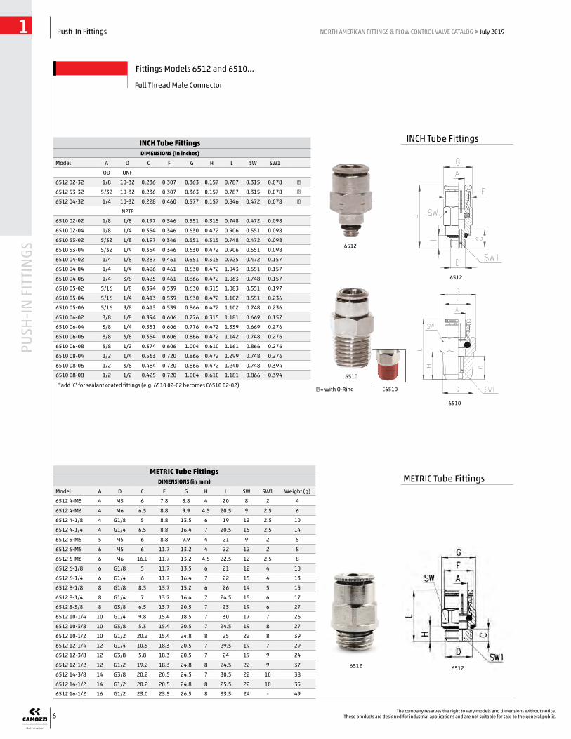
INCH Tube FittingsDIMENSIONS (in inches)
Model A D C F G H L SW SW1
OD UNF
6512 02-32 1/8 10-32 0.236 0.307 0.363 0.157 0.787 0.315 0.078 ●
6512 53-32 5/32 10-32 0.236 0.307 0.363 0.157 0.787 0.315 0.078 ●
6512 04-32 1/4 10-32 0.228 0.460 0.577 0.157 0.846 0.472 0.078 ●
NPTF
6510 02-02 1/8 1/8 0.197 0.346 0.551 0.315 0.748 0.472 0.098
6510 02-04 1/8 1/4 0.354 0.346 0.630 0.472 0.906 0.551 0.098
6510 53-02 5/32 1/8 0.197 0.346 0.551 0.315 0.748 0.472 0.098
6510 53-04 5/32 1/4 0.354 0.346 0.630 0.472 0.906 0.551 0.098
6510 04-02 1/4 1/8 0.287 0.461 0.551 0.315 0.925 0.472 0.157
6510 04-04 1/4 1/4 0.406 0.461 0.630 0.472 1.043 0.551 0.157
6510 04-06 1/4 3/8 0.425 0.461 0.866 0.472 1.063 0.748 0.157
6510 05-02 5/16 1/8 0.394 0.539 0.630 0.315 1.083 0.551 0.197
6510 05-04 5/16 1/4 0.413 0.539 0.630 0.472 1.102 0.551 0.236
6510 05-06 5/16 3/8 0.413 0.539 0.866 0.472 1.102 0.748 0.236
6510 06-02 3/8 1/8 0.394 0.606 0.776 0.315 1.181 0.669 0.157
6510 06-04 3/8 1/4 0.551 0.606 0.776 0.472 1.339 0.669 0.276
6510 06-06 3/8 3/8 0.354 0.606 0.866 0.472 1.142 0.748 0.276
6510 06-08 3/8 1/2 0.374 0.606 1.004 0.610 1.161 0.866 0.276
6510 08-04 1/2 1/4 0.563 0.720 0.866 0.472 1.299 0.748 0.276
6510 08-06 1/2 3/8 0.484 0.720 0.866 0.472 1.240 0.748 0.394
6510 08-08 1/2 1/2 0.425 0.720 1.004 0.610 1.181 0.866 0.394
METRIC Tube FittingsDIMENSIONS (in mm)
Model A D C F G H L SW SW1 Weight (g)
6512 4-M5 4 M5 6 7.8 8.8 4 20 8 2 4
6512 4-M6 4 M6 6.5 8.8 9.9 4.5 20.5 9 2.5 6
6512 4-1/8 4 G1/8 5 8.8 13.5 6 19 12 2.5 10
6512 4-1/4 4 G1/4 6.5 8.8 16.4 7 20.5 15 2.5 14
6512 5-M5 5 M5 6 8.8 9.9 4 21 9 2 5
6512 6-M5 6 M5 6 11.7 13.2 4 22 12 2 8
6512 6-M6 6 M6 16.0 11.7 13.2 4.5 22.5 12 2.5 8
6512 6-1/8 6 G1/8 5 11.7 13.5 6 21 12 4 10
6512 6-1/4 6 G1/4 6 11.7 16.4 7 22 15 4 13
6512 8-1/8 8 G1/8 8.5 13.7 15.2 6 26 14 5 15
6512 8-1/4 8 G1/4 7 13.7 16.4 7 24.5 15 6 17
6512 8-3/8 8 G3/8 6.5 13.7 20.5 7 23 19 6 27
6512 10-1/4 10 G1/4 9.8 15.4 18.5 7 30 17 7 26
6512 10-3/8 10 G3/8 5.3 15.4 20.5 7 24.5 19 8 27
6512 10-1/2 10 G1/2 20.2 15.4 24.8 8 25 22 8 39
6512 12-1/4 12 G1/4 10.5 18.3 20.5 7 29.5 19 7 29
6512 12-3/8 12 G3/8 5.8 18.3 20.5 7 24 19 9 24
6512 12-1/2 12 G1/2 19.2 18.3 24.8 8 24.5 22 9 37
6512 14-3/8 14 G3/8 20.2 20.5 24.5 7 30.5 22 10 38
6512 14-1/2 14 G1/2 20.2 20.5 24.8 8 25.5 22 10 35
6512 16-1/2 16 G1/2 23.0 23.5 26.5 8 33.5 24 - 49
● = with O-Ring
Fittings Models 6512 and 6510...
Full Thread Male Connector
6510
6510
6512
6512
*add ‘C’ for sealant coated fittings (e.g. 6510 02-02 becomes C6510 02-02)
6512 6512
INCH Tube Fittings
METRIC Tube Fittings
C6510

7
PUSH
-IN F
ITTI
NGS
Push-In Fittings1 NORTH AMERICAN FITTINGS & FLOW CONTROL VALVE CATALOG > July 2019
The company reserves the right to vary models and dimensions without notice.These products are designed for industrial applications and are not suitable for sale to the general public.
METRIC Tube FittingsDIMENSIONS (in mm)
Model A D F H L SW1 Weight (g)
6512 3-M3 3 M3 5.8 2.5 10.2 1.5 1 ●
6512 3-M5 3 M5 5.8 3.5 10 2 1 ●
6512 4-M7-M 4 M7 9.4 5 17.5 2.5 5 ●
6512 4-1/8-M 4 G1/8 11.2 5 13 2.5 9 ●
6512 6-M7-M 6 M7 10.4 5 17 4 7 ●
6512 6-1/8-M 6 G1/8 11.2 5 14 4 7 ●
6512 8-1/8-M 8 G1/8 12.4 5 18.5 5 10 ●
6512 10-1/4-M 10 G1/4 14.8 6 21 7 16 ●
Fittings Model 6512 Micro
INCH Tube FittingsDIMENSIONS (in inches)
Model A OD
D F H L SW
6512 02-32-M 1/8 10-32 UNF 0.307 0.157 0.630 0.079 ●
6512 04-32-M 1/4 10-32 UNF 0.409 0.157 0.669 0.079 ●
6512 04-M5-M 1/4 M5 0.409 0.157 0.669 0.079 ●
6512 04-M7-M 1/4 M7 0.413 0.197 0.669 0.157 ●
Micro Barrel Connector
● = with gasket ● = with O-Ring
● = with gasket ● = with O-Ring
INCH Tube FittingsDIMENSIONS (in inches)
Model A OD
DNPTF
E F H L M SW SW1
6110 04-02 1/4 1/8 0.630 0.500 0.315 1.555 0.827 0.433 0.472
6110 04-04 1/4 1/4 0.748 0.500 0.472 1.713 0.827 0.433 0.551
6110 06-04 3/8 1/4 0.847 0.650 0.472 1.969 1.043 0.591 0.669
6110 06-06 3/8 3/8 0.748 0.650 0.472 1.969 1.043 0.591 0.7486110
6512
65126512
6512
6110
45° Swivel Elbow
Fittings Model 6110 and Model S6110
METRIC Tube FittingsDIMENSIONS (in mm)
Model A D E F H L M SW SW1 Weight (g)
S6110 6-1/8 6 G1/8 14 12.7 5.5 32.5 20.5 11 12 21
S6110 6-1/4 6 G1/4 14 12.7 7 34.5 20.5 11 14 25
S6110 8-1/8 8 G1/8 14 14.2 5.5 32.5 22.5 11 12 21
S6110 8-1/4 8 G1/4 14 14.2 7 34.5 22.5 11 14 26
S6110 8-3/8 8 G3/8 14.5 14.2 8 35 22.5 11 19 38
S6110 10-1/4 10 G1/4 15.5 16.5 7 39.5 26.5 15 17 39
S6110 10-3/8 10 G3/8 15.5 16.5 8 39.5 26.5 15 19 44
S6110 10-1/2 10 G1/2 16 16.5 9 40 26.5 15 22 57
S6110 12-1/4 12 G1/4 15.5 19.5 7 40.5 26.5 15 17 41
S6110 12-3/8 12 G3/8 15.5 19.5 8 40.5 26.5 15 19 46
S6110 12-1/2 12 G1/2 16 19.5 9 41 26.5 15 22 59
*add ‘C’ for sealant coated fittings (e.g. 6110 04-02 becomes C6110 04-02)
S6110 S6110
INCH Tube Fittings
INCH Tube Fittings
METRIC Tube Fittings
METRIC Tube Fittings
C6110

8
PUSH
-IN F
ITTI
NGS
Push-In Fittings1 NORTH AMERICAN FITTINGS & FLOW CONTROL VALVE CATALOG > July 2019
The company reserves the right to vary models and dimensions without notice.These products are designed for industrial applications and are not suitable for sale to the general public.
METRIC Tube FittingsDIMENSIONS (in mm)
Model A D C E F H M SW SW1 Weight (g)
S6520 4-1/8 4 G1/8 3.5 14.5 9 5.5 17.5 8 12 17
S6520 4-1/4 4 G1/4 3.5 14.5 9 7 17.5 8 14 23
S6520 5-1/8 5 G1/8 5.5 14.5 10 5.5 20.5 9 12 17
S6520 5-1/4 5 G1/4 5.5 14.5 10 7 20.5 9 14 23
S6520 6-1/8 6 G1/8 4 15 12.7 5.5 20 9 12 20
S6520 6-1/4 6 G1/4 4 15 12.7 7 20 9 14 23
S6520 6-3/8 6 G3/8 4 15.5 12.7 8 20 9 19 33
S6520 8-1/8 8 G1/8 5 16 14.2 5.5 22.5 11 12 22
S6520 8-1/4 8 G1/4 5 16 14.2 7 22.5 11 14 26
S6520 8-3/8 8 G3/8 5 16.5 14.2 8 22.5 11 19 41
S6520 8-1/2 8 G1/2 5 17 14.2 9 22.5 11 22 48
S6520 10-1/4 10 G1/4 5.8 18.5 16.5 7 26 13 14 32
S6520 10-3/8 10 G3/8 5.8 19 16.5 8 26 13 19 43
S6520 10-1/2 10 G1/2 5.8 19.5 16.5 9 26 13 22 62
S6520 12-1/4 12 G1/4 7.3 20 19.5 7 26.5 15 17 49
S6520 12-3/8 12 G3/8 7.3 20 19.5 8 26.5 15 19 48
S6520 12-1/2 12 G1/2 7.3 20.5 19.5 9 26.5 15 22 70
S6520 14-3/8 14 G3/8 8.3 21 21.5 8 28.5 17 19 74
S6520 14-1/2 14 G1/2 8.3 21.5 21.5 9 28.5 17 22 78
INCH Tube FittingsDIMENSIONS (in inches)
Model A OD
D NPTF
C E F H M SW SW1
P6520 02-02 1/8 1/8 0.138 0.591 0.354 0.197 0.689 0.315 0.472
P6520 02-04 1/8 1/4 0.138 0.630 0.354 0.256 0.689 0.315 0.551
P6520 53-02 5/32 1/8 0.138 0.591 0.354 0.197 0.689 0.315 0.472
P6520 53-04 5/32 1/4 0.138 0.630 0.354 0.256 0.689 0.315 0.551
P6520 04-02 1/4 1/8 0.157 0.630 0.500 0.197 0.787 0.354 0.472
P6520 04-04 1/4 1/4 0.157 0.650 0.500 0.256 0.787 0.354 0.551
P6520 04-06 1/4 3/8 0.157 0.650 0.500 0.295 0.787 0.354 0.748
P6520 05-02 5/16 1/8 0.197 0.650 0.559 0.197 0.886 0.433 0.472
P6520 05-04 5/16 1/4 0.197 0.689 0.559 0.256 0.886 0.433 0.551
P6520 05-06 5/16 3/8 0.197 0.689 0.559 0.295 0.886 0.433 0.748
P6520 06-02 3/8 1/8 0.256 0.748 0.650 0.197 1.043 0.512 0.551
P6520 06-04 3/8 1/4 0.236 0.768 0.650 0.256 1.024 0.512 0.551
P6520 06-06 3/8 3/8 0.236 0.768 0.650 0.295 1.024 0.512 0.748
P6520 06-08 3/8 1/2 0.236 0.787 0.650 0.335 1.024 0.512 0.866
P6520 08-04 1/2 1/4 0.280 0.807 0.768 0.256 1.043 0.591 0.669
P6520 08-06 1/2 3/8 0.280 0.807 0.768 0.295 1.043 0.591 0.748
P6520 08-08 1/2 1/2 0.315 0.827 0.768 0.335 1.043 0.591 0.866
Fittings Model P6520 and S6520...
Pro-Fit® or Sprint® Male Elbow Swivel
P6520
P6520
S6520S6520
INCH Tube Fittings
METRIC Tube Fittings

9
PUSH
-IN F
ITTI
NGS
Push-In Fittings1 NORTH AMERICAN FITTINGS & FLOW CONTROL VALVE CATALOG > July 2019
The company reserves the right to vary models and dimensions without notice.These products are designed for industrial applications and are not suitable for sale to the general public.
INCH Tube FittingsDIMENSIONS (in inches)
Model A OD
D UNF
C E F H M SW SW1
6522 02-32 1/8 10-32 0.138 0.492 0.354 0.157 0.689 0.315 0.315 ●
6522 53-32 5/32 10-32 0.138 0.492 0.354 0.157 0.689 0.315 0.315 ●
6522 04-32 1/4 10-32 0.157 0.531 0.500 0.157 0.787 0.354 0.394 ●
NPTF
6520 02-02 1/8 1/8 0.138 0.650 0.354 0.315 0.689 0.315 0.472
6520 02-04 1/8 1/4 0.138 0.689 0.354 0.472 0.689 0.315 0.551
6520 53-02 5/32 1/8 0.138 0.650 0.354 0.315 0.689 0.315 0.472
6520 53-04 5/32 1/4 0.138 0.689 0.354 0.472 0.689 0.315 0.551
6520 04-02 1/4 1/8 0.157 0.669 0.500 0.315 0.787 0.354 0.472
6520 04-04 1/4 1/4 0.157 0.709 0.500 0.472 0.787 0.354 0.551
6520 04-06 1/4 3/8 0.157 0.689 0.500 0.472 0.787 0.354 0.748
6520 05-02 5/16 1/8 0.197 0.709 0.559 0.315 0.886 0.433 0.472
6520 05-04 5/16 1/4 0.197 0.748 0.559 0.472 0.886 0.433 0.551
6520 05-06 5/16 3/8 0.197 0.728 0.559 0.472 0.886 0.433 0.748
6520 06-02 3/8 1/8 0.256 0.807 0.650 0.315 1.043 0.512 0.551
6520 06-04 3/8 1/4 0.236 0.846 0.650 0.472 1.024 0.512 0.551
6520 06-06 3/8 3/8 0.236 0.827 0.650 0.472 1.024 0.512 0.748
6520 06-08 3/8 1/2 0.236 0.906 0.650 0.610 1.024 0.512 0.866
6520 08-04 1/2 1/4 0.280 0.906 0.768 0.472 1.043 0.591 0.669
6520 08-06 1/2 3/8 0.280 0.866 0.768 0.472 1.043 0.591 0.748
6520 08-08 1/2 1/2 0.280 0.945 0.768 0.610 1.043 0.591 0.866
METRIC Tube FittingsDIMENSIONS (in mm)
Model A D C E F H M SW SW1 Weight (g)
6522 4-M5 4 M5 3.5 12.5 9 4 17.5 8 8 12
6522 4-1/8 4 G1/8 3.5 14.5 9 6 17.5 8 12 15
6522 4-1/4 4 G1/4 3.5 15.5 9 7 17.5 8 15 25
6522 5-M5 5 M5 5.5 12.5 10 4 20.5 9 8 13
6522 6-M5 6 M5 4 13 12.7 4 20 9 10 14
6522 6-1/8 6 G1/8 4 15 12.7 6 20 9 12 19
6522 6-1/4 6 G1/4 4 16 12.7 7 20 9 15 27
6522 8-1/8 8 G1/8 5 16 14.2 6 22.5 11 12 22
6522 8-1/4 8 G1/4 5 17 14.2 7 22.5 11 15 28
6522 8-3/8 8 G3/8 5 17 14.2 7 22.5 11 19 45
6522 10-1/4 10 G1/4 5.8 19.5 16.5 7 26 13 15 41
6522 10-3/8 10 G3/8 5.8 19.5 16.5 7 26 13 19 45
6255 10-1/2 10 G1/2 20.2 20.5 16.5 8 26 13 22 53
6522 12-1/4 12 G1/4 7.3 20 19.5 7 26.5 15 17 51
6522 12-3/8 12 G3/8 7.3 20.5 19.5 7 26.5 15 19 56
6522 12-1/2 12 G1/2 19.2 21.5 19.5 8 26.5 15 22 58
6522 14-3/8 14 G3/8 20.2 21.5 21.5 7 28.5 17 19 53
6522 14-1/2 14 G1/2 20.2 22.5 21.5 8 28.5 17 22 61
METRIC Tube FittingsDIMENSIONS (in mm)
Model A D E H M SW SW1 Weight (g)
6522 3-M3 3 M3 13.7 2.5 13.7 6 6 4 ●
6522 3-M5 3 M5 13.7 3.5 13.7 6 8 5 ●
6522
6522 6522
6520
6520
Fittings Models 6522 and 6520...
Full Thread Male Elbow Swivel
● = with gasket ● = with O-Ring
6522 6522 ● = with gasket ● = with O-Ring
*add ‘C’ for sealant coated fittings (e.g. 6520 04-02 becomes C6520 04-02)
INCH Tube Fittings
METRIC Tube Fittings
6522
C6520
10
PUSH
-IN F
ITTI
NGS
Push-In Fittings1 NORTH AMERICAN FITTINGS & FLOW CONTROL VALVE CATALOG > July 2019
The company reserves the right to vary models and dimensions without notice.These products are designed for industrial applications and are not suitable for sale to the general public.
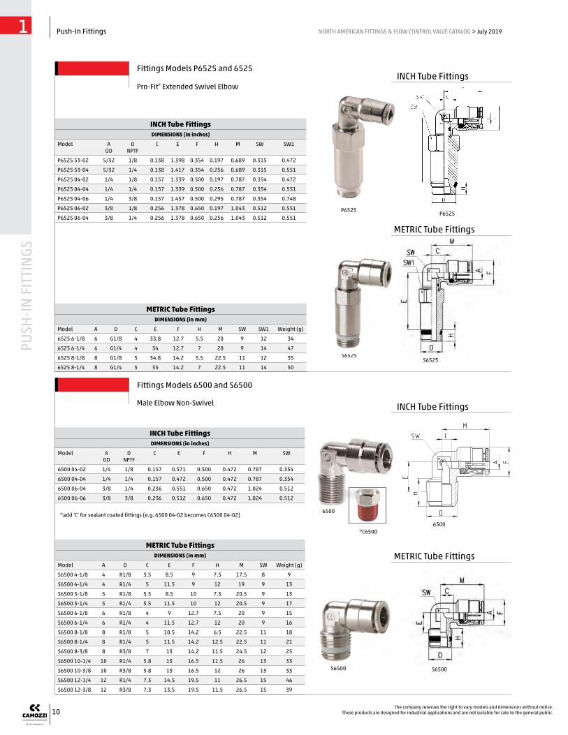
INCH Tube FittingsDIMENSIONS (in inches)
Model A OD
D NPTF
C E F H M SW
6500 04-02 1/4 1/8 0.157 0.571 0.500 0.472 0.787 0.354
6500 04-04 1/4 1/4 0.157 0.472 0.500 0.472 0.787 0.354
6500 06-04 3/8 1/4 0.236 0.551 0.650 0.472 1.024 0.512
6500 06-06 3/8 3/8 0.236 0.512 0.650 0.472 1.024 0.512
METRIC Tube FittingsDIMENSIONS (in mm)
Model A D C E F H M SW SW1 Weight (g)
6525 6-1/8 6 G1/8 4 33.8 12.7 5.5 20 9 12 34
6525 6-1/4 6 G1/4 4 34 12.7 7 20 9 14 47
6525 8-1/8 8 G1/8 5 34.8 14.2 5.5 22.5 11 12 35
6525 8-1/4 8 G1/4 5 35 14.2 7 22.5 11 14 50
METRIC Tube FittingsDIMENSIONS (in mm)
Model A D C E F H M SW Weight (g)
S6500 4-1/8 4 R1/8 3.5 8.5 9 7.5 17.5 8 9
S6500 4-1/4 4 R1/4 5 11.5 9 12 19 9 13
S6500 5-1/8 5 R1/8 5.5 8.5 10 7.5 20.5 9 13
S6500 5-1/4 5 R1/4 5.5 11.5 10 12 20.5 9 17
S6500 6-1/8 6 R1/8 4 9 12.7 7.5 20 9 15
S6500 6-1/4 6 R1/4 4 11.5 12.7 12 20 9 16
S6500 8-1/8 8 R1/8 5 10.5 14.2 6.5 22.5 11 18
S6500 8-1/4 8 R1/4 5 11.5 14.2 12.5 22.5 11 21
S6500 8-3/8 8 R3/8 7 13 14.2 11.5 24.5 12 25
S6500 10-1/4 10 R1/4 5.8 13 16.5 11.5 26 13 33
S6500 10-3/8 10 R3/8 5.8 13 16.5 12 26 13 33
S6500 12-1/4 12 R1/4 7.3 14.5 19.5 11 26.5 15 46
S6500 12-3/8 12 R3/8 7.3 13.5 19.5 11.5 26.5 15 39
INCH Tube FittingsDIMENSIONS (in inches)
Model A OD
DNPTF
C E F H M SW SW1
P6525 53-02 5/32 1/8 0.138 1.398 0.354 0.197 0.689 0.315 0.472
P6525 53-04 5/32 1/4 0.138 1.417 0.354 0.256 0.689 0.315 0.551
P6525 04-02 1/4 1/8 0.157 1.339 0.500 0.197 0.787 0.354 0.472
P6525 04-04 1/4 1/4 0.157 1.339 0.500 0.256 0.787 0.354 0.551
P6525 04-06 1/4 3/8 0.157 1.457 0.500 0.295 0.787 0.354 0.748
P6525 06-02 3/8 1/8 0.256 1.378 0.650 0.197 1.043 0.512 0.551
P6525 06-04 3/8 1/4 0.256 1.378 0.650 0.256 1.043 0.512 0.551
6500
*C6500
S6525S6525
P6525 P6525
6500
Fittings Models P6525 and 6525
Pro-Fit® Extended Swivel Elbow
Fittings Models 6500 and S6500
Male Elbow Non-Swivel
*add ‘C’ for sealant coated fittings (e.g. 6500 04-02 becomes C6500 04-02)
S6500 S6500
INCH Tube Fittings
INCH Tube Fittings
METRIC Tube Fittings
METRIC Tube Fittings

11
PUSH
-IN F
ITTI
NGS
Push-In Fittings1 NORTH AMERICAN FITTINGS & FLOW CONTROL VALVE CATALOG > July 2019
The company reserves the right to vary models and dimensions without notice.These products are designed for industrial applications and are not suitable for sale to the general public.
Fitting Model 6501 4-M5
Metric Non-swivel Male Elbow
METRIC Tube FittingsDIMENSIONS (in mm)
Model A D C E F H M SW Weight (g)
6501 4-M5 4 M5 3.5 6 9 4 17.5 8 v
Fittings Model 6622
Complete BSP Swivel Single Banjo
METRIC Tube FittingsDIMENSIONS (in mm)
Model A B C E F H L M SW W Weight (g)
6622 4-M5 4 M5 4 5.7 8.8 4 15.8 18 2.5 Ø 8 10
6622 4-1/8 4 G1/8 7.5 10.2 9 5 25 21.5 4 Ø 14 22
6622 6-1/8 6 G1/8 8 10.2 12.7 5 25 24 4 Ø 14 24
6622 6-1/4 6 G1/4 10 9.1 12.7 6 25.3 26 5 Ø 18 35
6622 8-1/8 8 G1/8 8 10.2 14.2 5 25 25.5 4 Ø 14 28
6622 8-1/4 8 G1/4 10 9.1 14.2 6 25.3 27.5 5 Ø 18 39
6622 10-1/4 10 G1/4 8.8 9.1 16.5 6 25.3 29 5 Ø 18 42
Fittings Model 6621 Micro
Complete Metric Single Banjo
METRIC Tube FittingsDIMENSIONS (in mm)
Model A B C F H L S W SW Weight (g)
6621 3-M3 3 M3 5.8 14.2 2.5 9.3 3.5 6 1.5 5
6621 3-M5 3 M5 6.5 16 3.2 11.9 4.8 8 2 6
6501
6621
6622
6632 6632
6622
6621
6501
Fittings Model 6632
Complete BSP Swivel Double Banjo
METRIC Tube FittingsDIMENSIONS (in mm)
Model A B C E F H L M W SW Weight (g)
6632 4-1/8 4 G1/8 7.5 10.2 9 5 25 43 Ø 14 4 24
6632 6-1/8 6 G1/8 8 10.2 12.7 5 25 48 Ø 14 4 33
6632 6-1/4 6 G1/4 10 9.1 12.7 6 25.3 52 Ø 18 5 35
6632 8-1/8 8 G1/8 8 10.2 14.2 5 25 51 Ø 14 4 39
6632 8-1/4 8 G1/4 10 9.1 14.2 6 25.3 55 Ø 18 5 40
6632 10-1/4 10 G1/4 8.8 9.1 16.5 6 25.3 58 Ø 18 5 50
METRIC Tube Fittings
METRIC Tube Fittings
METRIC Tube Fittings
METRIC Tube Fittings
12
PUSH
-IN F
ITTI
NGS
Push-In Fittings1 NORTH AMERICAN FITTINGS & FLOW CONTROL VALVE CATALOG > July 2019
The company reserves the right to vary models and dimensions without notice.These products are designed for industrial applications and are not suitable for sale to the general public.
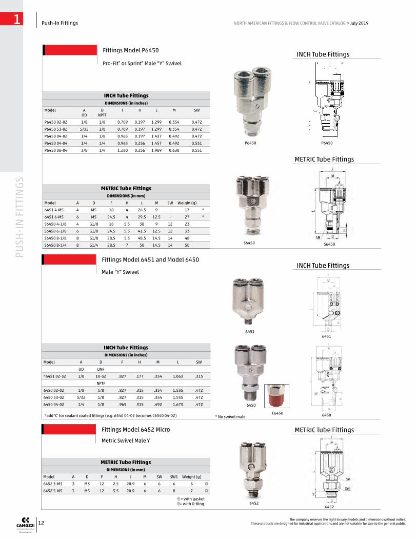
INCH Tube FittingsDIMENSIONS (in inches)
Model A D F H M L SW
OD UNF
*6451 02-32 1/8 10-32 .827 .177 .354 1.063 .315
NPTF
6450 02-02 1/8 1/8 .827 .315 .354 1.535 .472
6450 53-02 5/32 1/8 .827 .315 .354 1.535 .472
6450 04-02 1/4 1/8 .965 .315 .492 1.673 .472
* No swivel male
6450
6450
Fittings Model 6451 and Model 6450
Male “Y” Swivel
64516451
*add ‘C’ for sealant coated fittings (e.g. 6540 04-02 becomes C6540 04-02)
Fittings Model 6452 Micro
Metric Swivel Male Y
METRIC Tube FittingsDIMENSIONS (in mm)
Model A D F H L M SW SW1 Weight (g)
6452 3-M3 3 M3 12 2.5 20.9 6 6 6 6 ●
6452 3-M5 3 M5 12 3.5 20.9 6 6 8 7 ●
● = with gasket ●= with O-Ring
METRIC Tube FittingsDIMENSIONS (in mm)
Model A D F H L M SW Weight (g)
6451 4-M5 4 M5 18 4 26.5 9 - 17 *
6451 6-M5 6 M5 24.5 4 29.5 12.5 - 27 *
S6450 4-1/8 4 G1/8 18 5.5 38 9 12 23
S6450 6-1/8 6 G1/8 24.5 5.5 41.5 12.5 12 33
S6450 8-1/8 8 G1/8 28.5 5.5 48.5 14.5 14 48
S6450 8-1/4 8 G1/4 28.5 7 50 14.5 14 50
INCH Tube FittingsDIMENSIONS (in inches)
Model A OD
DNPTF
F H L M SW
P6450 02-02 1/8 1/8 0.709 0.197 1.299 0.354 0.472
P6450 53-02 5/32 1/8 0.709 0.197 1.299 0.354 0.472
P6450 04-02 1/4 1/8 0.965 0.197 1.437 0.492 0.472
P6450 04-04 1/4 1/4 0.965 0.256 1.457 0.492 0.551
P6450 06-04 3/8 1/4 1.260 0.256 1.969 0.630 0.551
Fittings Model P6450
Pro-Fit® or Sprint® Male “Y” Swivel
P6450 P6450
S6450 S6450
INCH Tube Fittings
INCH Tube Fittings
METRIC Tube Fittings
METRIC Tube Fittings
C6450
64526452

13
PUSH
-IN F
ITTI
NGS
Push-In Fittings1 NORTH AMERICAN FITTINGS & FLOW CONTROL VALVE CATALOG > July 2019
The company reserves the right to vary models and dimensions without notice.These products are designed for industrial applications and are not suitable for sale to the general public.
METRIC Tube FittingsDIMENSIONS (in mm)
Model A D C E F H L SW SW1 Weight (g)
S6430 4-1/8 4 G1/8 3.5 14.5 9 5.5 35 8 12 18
S6430 5-1/8 5 G1/8 5.5 14.5 10 5.5 41 9 12 24
S6430 5-1/4 5 G1/4 5.5 14.5 10 7 41 9 14 30
S6430 6-1/8 6 G1/8 4 15 12.7 5.5 40 9 12 28
S6430 6-1/4 6 G1/4 4 15 12.7 7 40 9 14 33
S6430 8-1/8 8 G1/8 5 16 14.2 5.5 45 11 12 37
S6430 8-1/4 8 G1/4 5 16 14.2 7 45 11 14 42
S6430 8-3/8 8 G3/8 5 16.5 14.2 8 45 11 19 51
S6430 10-1/4 10 G1/4 5.8 18.5 16.5 7 52 13 14 56
S6430 10-3/8 10 G3/8 5.8 19 16.5 8 52 13 19 67
S6430 10-1/2 10 G1/2 5.8 19.5 16.5 9 52 13 22 85
S6430 12-1/4 12 G1/4 7.3 20 19.5 7 53 15 17 60
S6430 12-3/8 12 G3/8 7.3 20 19.5 8 53 15 19 65
S6430 12-1/2 12 G1/2 7.3 20.5 19.5 9 53 15 22 89
S6430 14-1/2 14 G1/2 8.3 21.5 21.5 9 57 17 22 88
INCH Tube FittingsDIMENSIONS (in inches)
Model A OD
D NPTF
C E F H L SW SW1
P6430 02-02 1/8 1/8 0.138 0.591 0.354 0.197 1.378 0.315 0.472
P6430 53-02 5/32 1/8 0.138 0.591 0.354 0.197 1.378 0.315 0.472
P6430 53-04 5/32 1/4 0.138 0.630 0.354 0.256 1.378 0.315 0.551
P6430 04-02 1/4 1/8 0.157 0.630 0.500 0.197 1.575 0.354 0.472
P6430 04-04 1/4 1/4 0.157 0.650 0.500 0.256 1.575 0.354 0.551
P6430 04-06 1/4 3/8 0.157 0.650 0.500 0.295 1.575 0.354 0.748
P6430 06-04 3/8 1/4 0.236 0.768 0.650 0.256 2.047 0.512 0.551
P6430 06-06 3/8 3/8 0.236 0.768 0.650 0.295 2.047 0.512 0.748
P6430 06-08 3/8 1/2 0.256 0.787 0.650 0.335 2.087 0.512 0.866
P6430 08-04 1/2 1/4 0.280 0.807 0.768 0.256 2.087 0.591 0.669
P6430 08-06 1/2 3/8 0.280 0.807 0.768 0.295 2.087 0.591 0.748
P6430 08-08 1/2 1/2 0.280 0.827 0.768 0.335 2.087 0.591 0.866
P6430
S6430S6430
P6430
Fittings Model P6430...
Pro-Fit® or Sprint® Male Branch Tee Swivel
INCH Tube Fittings
METRIC Tube Fittings

14
PUSH
-IN F
ITTI
NGS
Push-In Fittings1 NORTH AMERICAN FITTINGS & FLOW CONTROL VALVE CATALOG > July 2019
The company reserves the right to vary models and dimensions without notice.These products are designed for industrial applications and are not suitable for sale to the general public.
METRIC Tube FittingsDIMENSIONS (in mm)
Model A D C E F H L SW SW1 Weight (g))
6432 4-M5 4 M5 3.5 12.5 9 4 35 8 8 14
6432 4-1/8 4 G1/8 3.5 14.5 9 6 35 8 12 19
6432 5-M5 5 M5 5.5 12.5 10 4 41 9 8 19
6432 6-1/8 6 G1/8 4 15 12.7 6 40 9 12 29
6432 6-1/4 6 G1/4 4 16 12.7 7 40 9 15 30
6432 8-1/8 8 G1/8 5 16 14.2 6 45 11 12 37
6432 8-1/4 8 G1/4 5 17 14.2 7 45 11 15 39
6432 8-3/8 8 G3/8 5 17 14.2 7 45 11 19 55
6432 10-1/4 10 G1/4 5.8 19.5 16.5 7 52 13 15 59
6432 10-3/8 10 G3/8 5.8 19.5 16.5 7 52 13 19 56
6432 12-1/4 12 G1/4 7.3 20 19.5 7 53 15 17 60
6432 12-3/8 12 G3/8 7.3 20.5 19.5 7 53 15 19 80
INCH Tube FittingsDIMENSIONS (in inches)
Model A D C E F H L SW SW1
OD UNF
6432 02-32 1/8 10-32 0.138 0.492 0.354 0.157 1.378 0.315 0.315
6432 53-32 5/32 10-32 0.138 0.492 0.354 0.157 1.378 0.315 0.315
NPTF
6430 02-02 1/8 1/8 0.138 0.650 - 0.315 1.378 0.315 0.472
6430 53-02 5/32 1/8 0.138 0.650 - 0.315 1.378 0.315 0.472
6430 53-04 5/32 1/4 0.138 0.689 - 0.472 1.378 0.315 0.551
6430 04-02 1/4 1/8 0.157 0.669 0.500 0.315 1.575 0.354 0.472
6430 04-04 1/4 1/4 0.157 0.709 0.500 0.472 1.575 0.354 0.551
6430 04-06 1/4 3/8 0.157 0.689 0.500 0.472 1.575 0.354 0.748
6430 06-04 3/8 1/4 0.236 0.846 - 0.472 2.047 0.512 0.551
6430 06-06 3/8 3/8 0.236 0.827 - 0.472 2.047 0.512 0.748
6430 06-08 3/8 1/2 0.256 0.906 - 0.610 2.087 0.512 0.866
6430 08-04 1/2 1/4 0.280 0.906 0.768 0.472 2.087 0.591 0.669
6430 08-06 1/2 3/8 0.280 0.866 0.768 0.472 2.087 0.591 0.748
6430 08-08 1/2 1/2 0.280 0.945 0.768 0.610 2.087 0.591 0.866
64326432
6430
6430
Fittings Model 6432 and Model 6430...
Male Branch Tee Swivel
6432 6432
INCH Tube Fittings
METRIC Tube Fittings
C6430

15
PUSH
-IN F
ITTI
NGS
Push-In Fittings1 NORTH AMERICAN FITTINGS & FLOW CONTROL VALVE CATALOG > July 2019
The company reserves the right to vary models and dimensions without notice.These products are designed for industrial applications and are not suitable for sale to the general public.
METRIC Tube FittingsDIMENSIONS (in mm)
Model A D C E F H L M SW SW1 Weight (g)
S6440 4-1/8 4 G1/8 3.5 14.5 9 5.5 37.5 17.5 8 12 23
S6440 5-1/8 5 G1/8 5.5 14.5 10 5.5 40.5 20.5 9 12 24
S6440 6-1/8 6 G1/8 4 15 12.7 5.5 40.5 20 9 12 26
S6440 6-1/4 6 G1/4 4 15 12.7 7 42 20 9 14 31
S6440 8-1/8 8 G1/8 5 16 14.2 5.5 44 22.5 11 12 37
S6440 8-1/4 8 G1/4 5 16 14.2 7 45.5 22.5 11 14 35
S6440 8-3/8 8 G3/8 5 16.5 14.2 8 47 22.5 11 19 52
S6440 10-1/4 10 G1/4 5.8 18.5 16.5 7 51.5 26 13 14 43
S6440 10-3/8 10 G3/8 5.8 18.5 16.5 8 53 26 13 19 66
S6440 12-3/8 12 G3/8 7.3 19.5 19.5 8 54.5 26.5 15 19 65
S6440 14-1/2 14 G1/2 8.3 21.5 21.5 9 59 28.5 17 22 88
INCH Tube FittingsDIMENSIONS (in inches)
Model A OD
DNPTF
C E F H L M SW SW1
P6440 02-02 1/8 1/8 0.138 0.591 0.354 0.197 1.476 0.689 0.315 0.472
P6440 53-02 5/32 1/8 0.138 0.591 0.354 0.197 1.476 0.689 0.315 0.472
P6440 53-04 5/32 1/4 0.138 0.630 0.354 0.256 1.575 0.689 0.315 0.551
P6440 04-02 1/4 1/8 0.157 0.630 0.500 0.197 1.614 0.787 0.354 0.472
P6440 04-04 1/4 1/4 0.157 0.650 0.500 0.256 1.693 0.787 0.354 0.551
P6440 04-06 1/4 3/8 0.157 0.650 0.500 0.295 1.732 0.787 0.354 0.748
P6440 06-04 3/8 1/4 0.256 0.768 0.650 0.256 2.067 1.024 0.512 0.551
P6440 06-06 3/8 3/8 0.256 0.768 0.650 0.295 2.106 1.024 0.512 0.748
P6440 06-08 3/8 1/2 0.256 0.787 0.650 0.335 2.165 1.043 0.512 0.866
P6440 08-04 1/2 1/4 0.315 0.807 0.768 0.256 2.106 1.043 0.591 0.669
P6440 08-06 1/2 3/8 0.315 0.807 0.768 0.295 2.146 1.043 0.591 0.748
P6440 08-08 1/2 1/2 0.315 0.827 0.768 0.335 2.205 1.043 0.591 0.866
S6440
Fittings Model P6440...
Pro-Fit® or Sprint® Male Run Tee Swivel
S6440
P6440
INCH Tube Fittings
METRIC Tube Fittings
P6440
16
PUSH
-IN F
ITTI
NGS
Push-In Fittings1 NORTH AMERICAN FITTINGS & FLOW CONTROL VALVE CATALOG > July 2019
The company reserves the right to vary models and dimensions without notice.These products are designed for industrial applications and are not suitable for sale to the general public.
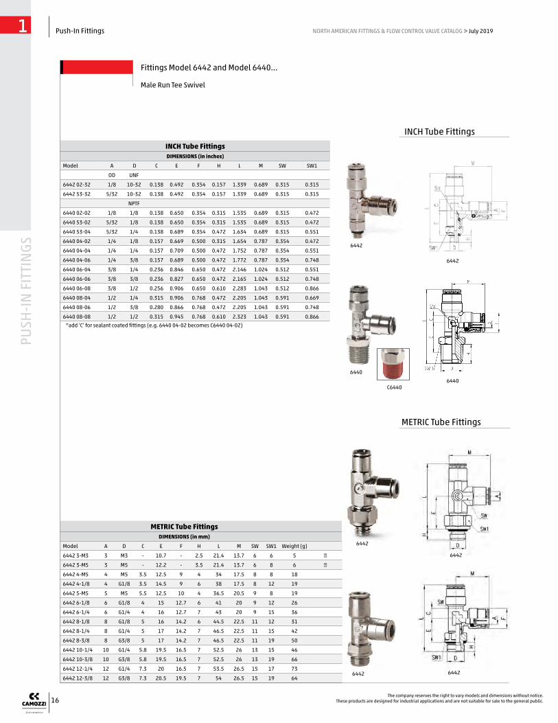
METRIC Tube FittingsDIMENSIONS (in mm)
Model A D C E F H L M SW SW1 Weight (g)
6442 3-M3 3 M3 - 10.7 - 2.5 21.4 13.7 6 6 5 ●
6442 3-M5 3 M5 - 12.2 - 3.5 21.4 13.7 6 8 6 ●
6442 4-M5 4 M5 3.5 12.5 9 4 34 17.5 8 8 18
6442 4-1/8 4 G1/8 3.5 14.5 9 6 38 17.5 8 12 19
6442 5-M5 5 M5 5.5 12.5 10 4 36.5 20.5 9 8 19
6442 6-1/8 6 G1/8 4 15 12.7 6 41 20 9 12 26
6442 6-1/4 6 G1/4 4 16 12.7 7 43 20 9 15 36
6442 8-1/8 8 G1/8 5 16 14.2 6 44.5 22.5 11 12 31
6442 8-1/4 8 G1/4 5 17 14.2 7 46.5 22.5 11 15 42
6442 8-3/8 8 G3/8 5 17 14.2 7 46.5 22.5 11 19 50
6442 10-1/4 10 G1/4 5.8 19.5 16.5 7 52.5 26 13 15 46
6442 10-3/8 10 G3/8 5.8 19.5 16.5 7 52.5 26 13 19 66
6442 12-1/4 12 G1/4 7.3 20 16.5 7 53.5 26.5 15 17 73
6442 12-3/8 12 G3/8 7.3 20.5 19.5 7 54 26.5 15 19 64
INCH Tube FittingsDIMENSIONS (in inches)
Model A D C E F H L M SW SW1
OD UNF
6442 02-32 1/8 10-32 0.138 0.492 0.354 0.157 1.339 0.689 0.315 0.315
6442 53-32 5/32 10-32 0.138 0.492 0.354 0.157 1.339 0.689 0.315 0.315
NPTF
6440 02-02 1/8 1/8 0.138 0.650 0.354 0.315 1.535 0.689 0.315 0.472
6440 53-02 5/32 1/8 0.138 0.650 0.354 0.315 1.535 0.689 0.315 0.472
6440 53-04 5/32 1/4 0.138 0.689 0.354 0.472 1.634 0.689 0.315 0.551
6440 04-02 1/4 1/8 0.157 0.669 0.500 0.315 1.654 0.787 0.354 0.472
6440 04-04 1/4 1/4 0.157 0.709 0.500 0.472 1.752 0.787 0.354 0.551
6440 04-06 1/4 3/8 0.157 0.689 0.500 0.472 1.772 0.787 0.354 0.748
6440 06-04 3/8 1/4 0.236 0.846 0.650 0.472 2.146 1.024 0.512 0.551
6440 06-06 3/8 3/8 0.236 0.827 0.650 0.472 2.165 1.024 0.512 0.748
6440 06-08 3/8 1/2 0.256 0.906 0.650 0.610 2.283 1.043 0.512 0.866
6440 08-04 1/2 1/4 0.315 0.906 0.768 0.472 2.205 1.043 0.591 0.669
6440 08-06 1/2 3/8 0.280 0.866 0.768 0.472 2.205 1.043 0.591 0.748
6440 08-08 1/2 1/2 0.315 0.945 0.768 0.610 2.323 1.043 0.591 0.866
6442
6442
64406440
*add ‘C’ for sealant coated fittings (e.g. 6440 04-02 becomes C6440 04-02)
Fittings Model 6442 and Model 6440...
Male Run Tee Swivel
6442 6442
INCH Tube Fittings
METRIC Tube Fittings
6442
6442
C6440

17
PUSH
-IN F
ITTI
NGS
Push-In Fittings1 NORTH AMERICAN FITTINGS & FLOW CONTROL VALVE CATALOG > July 2019
The company reserves the right to vary models and dimensions without notice.These products are designed for industrial applications and are not suitable for sale to the general public.
INCH Tube FittingsDIMENSIONS (in inches)
Model A OD
DNPTF
E F H L M SW SW1
6523 53-02 5/32 1/8 0.138 0.354 0.276 0.787 0.689 0.315 0.512
6523 53-04 5/32 1/4 0.138 0.354 0.394 1.004 0.689 0.315 0.669
6523 04-02 1/4 1/8 0.177 0.500 0.276 0.807 0.807 0.354 0.512
6523 04-04 1/4 1/4 0.177 0.500 0.394 0.965 0.807 0.354 0.669
6523 04-06 1/4 3/8 0.177 0.500 0.413 0.984 0.807 0.354 0.787
6523 06-04 3/8 1/4 0.236 0.650 0.394 1.102 1.024 0.512 0.669
6523 06-06 3/8 3/8 0.236 0.650 0.413 1.122 1.024 0.512 0.787
Fittings Model 6523
Female Swivel Elbow
INCH Tube FittingsDIMENSIONS (in inches)
Model A OD
D NPTF
C F G L SW
6463 02-02 1/8 1/8 0.394 0.354 0.512 0.945 0.472
6463 02-04 1/8 1/4 0.551 0.354 0.650 1.102 0.591
6463 53-02 5/32 1/8 0.394 0.354 0.512 0.945 0.472
6463 53-04 5/32 1/4 0.551 0.354 0.650 1.102 0.591
6463 04-02 1/4 1/8 0.386 0.461 0.512 1.024 0.472
6463 04-04 1/4 1/4 0.543 0.469 0.650 1.181 0.591
6463 06-04 3/8 1/4 0.512 0.606 0.728 1.299 0.669
6463 06-06 3/8 3/8 0.551 0.606 0.787 1.339 0.669
Fittings Model 6463...
Female Connector
METRIC Tube FittingsDIMENSIONS (in mm)
Model A D C F G L P (min) SW Weight (g)
6463 4-M5 4 M5 6.5 7.8 8.8 20.5 4.5 9 8
6463 4-1/8 4 G1/8 10 9 13 24 6 12 14
6463 5-1/8 5 G1/8 10 9.8 13 25 6 12 14
6463 6-1/8 6 G1/8 10 11.7 13 26 6 12 14
6463 6-1/4 6 G1/4 11.5 11.9 16.5 27.5 7 15 23
6463 8-1/8 8 G1/8 9.5 13.7 15.2 27 6 14 16
6463 8-1/4 8 G1/4 11.5 13.7 16.5 29 7 15 23
6463 10-1/4 10 G1/4 11.3 15.4 18.5 31.5 7 17 29
METRIC Tube FittingsDIMENSIONS (in mm)
Model A D E F G H L K (max) K (min) SW SW1 Weight (g)
6593 6-1/8 6 G1/8 10 M12x1 16.4 6 24.5 8.5 2 15 17 19
6593 6-1/4 6 G1/4 11.5 M12x1 18.5 7 26 6.5 2 17 17 22
6593 8-1/8 8 G1/8 10 M15x1 18.5 6 27 9.5 2 17 19 26
6593 8-1/4 8 G1/4 11.5 M15x1 18.5 7 28.5 9.5 2 17 19 26
6593 10-3/8 10 G3/8 12.8 M18x1 24.5 8 32.5 12 2 22 22 43
INCH Tube FittingsDIMENSIONS (in inches)
Model A OD
D NPTF
E F G H Kmax Kmin L SW SW1
6593 04-04 1/4 1/4 0.531 M12x1 0.650 0.394 0.256 0.079 1.102 0.669 0.669
6593 06-06 3/8 3/8 0.531 M18x1 0.787 0.413 0.472 0.079 1.339 0.866 0.866
6593 08-06 1/2 3/8 0.492 M20x1 0.787 0.413 0.472 0.079 1.299 0.945 0.945
Fittings Model 6593
Female Bulkhead
INCH Tube Fittings
INCH Tube Fittings
INCH Tube Fittings
METRIC Tube Fittings
METRIC Tube Fittings
6463
6463
65936593
6593
6523
6523
6593
6463
6463

18
PUSH
-IN F
ITTI
NGS
Push-In Fittings1 NORTH AMERICAN FITTINGS & FLOW CONTROL VALVE CATALOG > July 2019
The company reserves the right to vary models and dimensions without notice.These products are designed for industrial applications and are not suitable for sale to the general public.
METRIC Tube FittingsDIMENSIONS (in mm)
Model A C F M SW Weight (g)
6550 4 4 3.5 9 17.5 8 8
6550 5 5 5.5 10 20.5 9 15
6550 6 6 4 12.7 20 9 17
6550 8 8 5 14.2 22.5 11 22
6550 10 10 5.8 16.5 26 13 30
6550 12 12 7.3 19.5 26.5 15 44
6550 14 14 8.3 21.5 28.5 17 71
INCH Tube FittingsDIMENSIONS (in inches)
Model A OD
C F M SW
6550 02-00 1/8 0.138 0.354 0.689 0.315
6550 53-00 5/32 0.138 0.354 0.689 0.315
6550 04-00 1/4 0.157 0.500 0.787 0.354
6550 05-00 5/16 0.197 0.559 0.886 0.433
6550 06-00 3/8 0.236 0.650 1.024 0.512
6550 08-00 1/2 0.280 0.768 1.043 0.591
Fittings Model 6550...
Union Elbow
INCH Tube FittingsDIMENSIONS (in inches)
Model A OD
B OD
C D F G M N SW
6550 04-53 1/4 5/32 0.177 0.157 0.500 0.394 0.807 0.709 0.354
6550 06-04 3/8 1/4 0.236 0.177 0.650 0.500 1.024 0.827 0.512
6550 08-06 1/2 3/8 0.295 0.256 0.768 0.650 1.043 1.043 0.591
Fittings Model 6550
Reducing Union Elbow
Fittings Model 6550 Micro
Elbow Union
METRIC Tube FittingsDIMENSIONS (in mm)
Model A M SW Weight (g)
6550 3 3 13.7 6 3
INCH Tube Fittings
INCH Tube Fittings
METRIC Tube Fittings
65506550
6550
6550 6550
65506550
6550
19
PUSH
-IN F
ITTI
NGS
Push-In Fittings1 NORTH AMERICAN FITTINGS & FLOW CONTROL VALVE CATALOG > July 2019
The company reserves the right to vary models and dimensions without notice.These products are designed for industrial applications and are not suitable for sale to the general public.
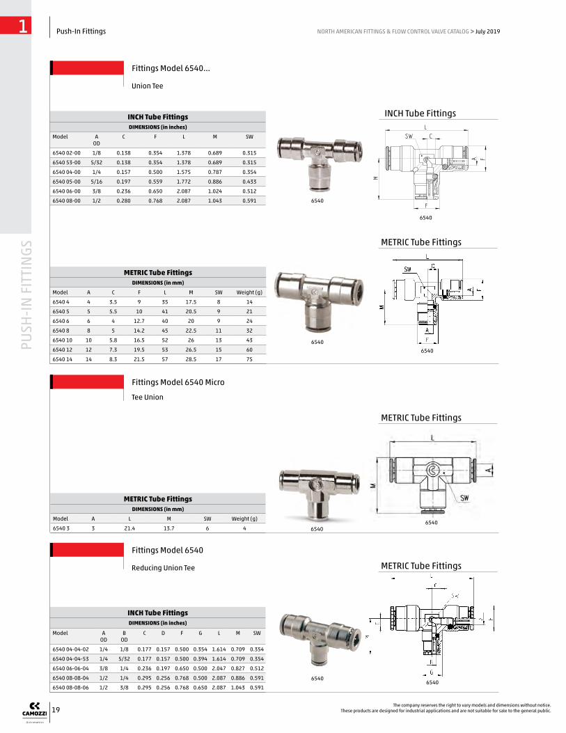
METRIC Tube FittingsDIMENSIONS (in mm)
Model A C F L M SW Weight (g)
6540 4 4 3.5 9 35 17.5 8 14
6540 5 5 5.5 10 41 20.5 9 21
6540 6 6 4 12.7 40 20 9 24
6540 8 8 5 14.2 45 22.5 11 32
6540 10 10 5.8 16.5 52 26 13 43
6540 12 12 7.3 19.5 53 26.5 15 60
6540 14 14 8.3 21.5 57 28.5 17 75
INCH Tube FittingsDIMENSIONS (in inches)
Model A OD
C F L M SW
6540 02-00 1/8 0.138 0.354 1.378 0.689 0.315
6540 53-00 5/32 0.138 0.354 1.378 0.689 0.315
6540 04-00 1/4 0.157 0.500 1.575 0.787 0.354
6540 05-00 5/16 0.197 0.559 1.772 0.886 0.433
6540 06-00 3/8 0.236 0.650 2.087 1.024 0.512
6540 08-00 1/2 0.280 0.768 2.087 1.043 0.591
Fittings Model 6540...
Union Tee
INCH Tube FittingsDIMENSIONS (in inches)
Model A OD
B OD
C D F G L M SW
6540 04-04-02 1/4 1/8 0.177 0.157 0.500 0.354 1.614 0.709 0.354
6540 04-04-53 1/4 5/32 0.177 0.157 0.500 0.394 1.614 0.709 0.354
6540 06-06-04 3/8 1/4 0.236 0.197 0.650 0.500 2.047 0.827 0.512
6540 08-08-04 1/2 1/4 0.295 0.256 0.768 0.500 2.087 0.886 0.591
6540 08-08-06 1/2 3/8 0.295 0.256 0.768 0.650 2.087 1.043 0.591
Fittings Model 6540
Reducing Union Tee
Fittings Model 6540 Micro
Tee Union
METRIC Tube FittingsDIMENSIONS (in mm)
Model A L M SW Weight (g)
6540 3 3 21.4 13.7 6 4
INCH Tube Fittings
METRIC Tube Fittings
METRIC Tube Fittings
METRIC Tube Fittings
6540
65406540
65406540
6540
65406540

20
PUSH
-IN F
ITTI
NGS
Push-In Fittings1 NORTH AMERICAN FITTINGS & FLOW CONTROL VALVE CATALOG > July 2019
The company reserves the right to vary models and dimensions without notice.These products are designed for industrial applications and are not suitable for sale to the general public.
INCH Tube FittingsDIMENSIONS (in inches)
Model A OD
C F L M
6560 02-00 1/8 0.197 0.709 1.299 0.354
6560 53-00 5/32 0.197 0.709 1.299 0.354
6560 04-00 1/4 0.256 0.965 1.535 0.492
6560 06-00 3/8 0.531 1.260 2.106 0.630
METRIC Tube FittingsDIMENSIONS (in mm)
Model A C F L M Weight (g)
6560 4 4 5 18 33 9 19
6560 6 6 7 24.5 39 12.5 30
6560 8 8 9 28.5 44 14.5 42
6560 10 10 15.5 32 53.5 16 63
Fittings Model 6560
Union “Y”
Fittings Model 6560 Micro
Y Union
METRIC Tube FittingsDIMENSIONS (in mm)
Model A F L M SW Weight (g)
6560 3 3 12 20.4 6 6 5
Fittings Model 6600
Cross Union
METRIC Tube FittingsDIMENSIONS (in mm)
Model A F L M SW Weight (g)
6600 4 4 9 38 19 9 26
6600 5 5 10 41 20.5 9 29
6600 6 6 12.7 44 22 10 35
6600 8 8 14.2 49 24.5 12 50
6600 10 10 16.5 55 27.5 14 63
6600 12 12 19.5 56 28 16 84
6560
6560
6560
6560
INCH Tube Fittings
METRIC Tube Fittings
METRIC Tube Fittings
METRIC Tube Fittings
6600
6560 6560
6600

21
PUSH
-IN F
ITTI
NGS
Push-In Fittings1 NORTH AMERICAN FITTINGS & FLOW CONTROL VALVE CATALOG > July 2019
The company reserves the right to vary models and dimensions without notice.These products are designed for industrial applications and are not suitable for sale to the general public.
METRIC Tube FittingsDIMENSIONS (in mm)
Model A F G L N S S1 S2 Weight (g)
6580 3 3 5.8 19.9 - 2.2 - - 2
6580 4 4 8.4 9 29 14 5 2.2 1.6 11
6580 5 5 9.4 10 31 15 5 2.2 1.6 15
6580 6 6 11.7 12 34 16 5 2.2 1.6 16
6580 8 8 13.7 14 37 17.5 5 2.2 1.6 23
6580 10 10 15.4 17 41.5 20.2 5 2.2 1.6 33
6580 12 12 18.3 19 39.5 19.2 5.2 2.2 1.6 40
6580 14 14 20.5 21 41.5 20.2 5.2 2.2 1.6 47
6580 16 16 - 47 47 23 - - - 60
METRIC Tube FittingsDIMENSIONS (in mm)
Model A B F G L M N Weight (g)
6580 6-4 6 4 12 9 31.5 16 14 12
6580 8-6 8 6 14 12.2 35 17.5 16 19
6580 10-8 10 8 16 14 39 20 17.5 25
6580 12-10 12 10 19 16 40.5 19 20 35
INCH Tube FittingsDIMENSIONS (in inches)
Model A OD
F G L N
6580 02-00 1/8 0.331 0.354 1.142 0.551
6580 53-00 5/32 0.331 0.354 1.142 0.551
6580 04-00 1/4 0.461 0.472 1.319 0.638
6580 05-00 5/16 0.539 0.551 1.457 0.689
6580 06-00 3/8 0.606 0.669 1.614 0.787
6580 08-00 1/2 0.720 0.748 1.555 0.756
Fittings Model 6580...
Union
INCH Tube FittingsDIMENSIONS (in inches)
Model A OD
B OD
F G L M N
6580 04-02 1/4 1/8 0.472 0.362 1.240 0.630 0.551
6580 04-53 1/4 5/32 0.472 0.362 1.240 0.630 0.551
6580 06-04 3/8 1/4 0.630 0.472 1.496 0.787 0.630
Fittings Model 6580
Reducing Union
INCH Tube Fittings
INCH Tube Fittings
METRIC Tube Fittings
METRIC Tube Fittings
6580
6580
6580
6580
6580
6580
6580
6580

22
PUSH
-IN F
ITTI
NGS
Push-In Fittings1 NORTH AMERICAN FITTINGS & FLOW CONTROL VALVE CATALOG > July 2019
The company reserves the right to vary models and dimensions without notice.These products are designed for industrial applications and are not suitable for sale to the general public.
METRIC Tube FittingsDIMENSIONS (in mm)
Model A B F L N MAX SW SW1 T Weight (g)
6590 4 4 M10x1 8.8 29 14 10.5 14 14 20 16
6590 5 5 M12x1 9.8 31 15 10.5 17 17 20 25
6590 6 6 M14x1 12.5 33 16 10.5 17 17 20 28
6590 8 8 M16x1 14.5 36 17.5 11.5 19 19 21 35
6590 10 10 M18x1 16.3 41.5 20.2 13 22 22 23.5 51
6590 12 12 M20x1 18.8 39.5 19.2 14.5 24 24 25 56
6590 14 14 M22x1 20.5 41.5 20.2 17.5 27 27 30 82
INCH Tube FittingsDIMENSIONS (in inches)
Model A OD
B F L N MAX SW SW1 T
6590 02-00 1/8 M10X1 0.346 1.142 0.551 0.453 0.551 0.551 0.866
6590 53-00 5/32 M10X1 0.346 1.142 0.551 0.413 0.551 0.551 0.866
6590 04-00 1/4 M14X1 0.492 1.319 0.638 0.453 0.669 0.669 0.925
6590 05-00 5/16 M16X1 0.571 1.417 0.689 0.453 0.748 0.748 0.925
6590 06-00 3/8 M18X1 0.622 1.614 0.787 0.512 0.866 0.866 1.024
6590 08-00 1/2 M20X1 0.740 1.555 0.756 0.571 0.945 0.945 1.083
Fittings Model 6590...
Bulkhead Union
Fittings Model 6590 Micro
METRIC Tube FittingsDIMENSIONS (in mm)
Model A B F L MAX T Weight (g)
6590 3 3 M7x0.75 5.8 18.4 5 11.4 4
Bulkhead Union
INCH Tube Fittings
METRIC Tube Fittings
METRIC Tube Fittings
65906590
65906590
65906590
23
PUSH
-IN F
ITTI
NGS
Push-In Fittings1 NORTH AMERICAN FITTINGS & FLOW CONTROL VALVE CATALOG > July 2019
The company reserves the right to vary models and dimensions without notice.These products are designed for industrial applications and are not suitable for sale to the general public.
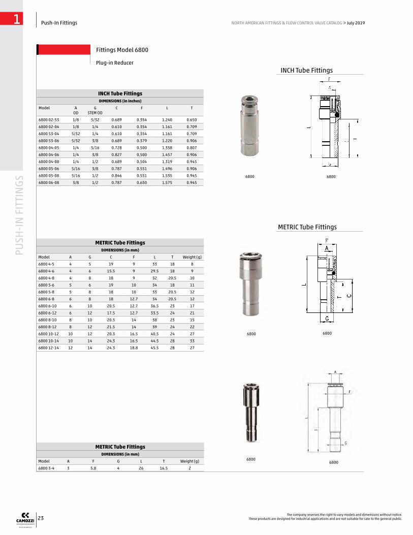
METRIC Tube FittingsDIMENSIONS (in mm)
Model A F G L T Weight (g)
6800 3-4 3 5.8 4 26 16.5 2
METRIC Tube FittingsDIMENSIONS (in mm)
Model A G C F L T Weight (g)
6800 4-5 4 5 19 9 33 18 8
6800 4-6 4 6 15.5 9 29.5 18 9
6800 4-8 4 8 18 9 32 20.5 10
6800 5-6 5 6 19 10 34 18 11
6800 5-8 5 8 18 10 33 20.5 12
6800 6-8 6 8 18 12.7 34 20.5 12
6800 6-10 6 10 20.5 12.7 36.5 23 17
6800 6-12 6 12 17.5 12.7 33.5 24 21
6800 8-10 8 10 20.5 14 38 23 15
6800 8-12 8 12 21.5 14 39 24 22
6800 10-12 10 12 20.3 16.5 40.5 24 27
6800 10-14 10 14 24.3 16.5 44.5 28 33
6800 12-14 12 14 24.3 18.8 45.5 28 27
INCH Tube FittingsDIMENSIONS (in inches)
Model A OD
G STEM OD
C F L T
6800 02-53 1/8 5/32 0.689 0.354 1.240 0.650
6800 02-04 1/8 1/4 0.610 0.354 1.161 0.709
6800 53-04 5/32 1/4 0.610 0.354 1.161 0.709
6800 53-06 5/32 3/8 0.689 0.379 1.220 0.906
6800 04-05 1/4 5/16 0.728 0.500 1.358 0.807
6800 04-06 1/4 3/8 0.827 0.500 1.457 0.906
6800 04-08 1/4 1/2 0.689 0.504 1.319 0.945
6800 05-06 5/16 3/8 0.787 0.551 1.496 0.906
6800 05-08 5/16 1/2 0.846 0.551 1.535 0.945
6800 06-08 3/8 1/2 0.787 0.650 1.575 0.945
Fittings Model 6800
Plug-in ReducerINCH Tube Fittings
METRIC Tube Fittings
68006800
6800
68006800
6800

24
PUSH
-IN F
ITTI
NGS
Push-In Fittings1 NORTH AMERICAN FITTINGS & FLOW CONTROL VALVE CATALOG > July 2019
The company reserves the right to vary models and dimensions without notice.These products are designed for industrial applications and are not suitable for sale to the general public.
METRIC Tube FittingsDIMENSIONS (in mm)
Model A G C L F T M SW Weight (g)
6555 4-4 4 4 3.5 22 9 16.5 17.5 9 8
6555 6-6 6 6 4 24.5 12.7 18 20 9 14
6555 8-8 8 8 5 27.5 14.2 20 22.5 11 21
6555 10-10 10 10 5.8 32 16.5 23 26 13 26
INCH Tube FittingsDIMENSIONS (in inches)
Model A OD
G STEM
OD
C L F T M SW
6555 53-53 5/32 5/32 0.138 0.866 0.354 0.650 0.689 0.315
6555 04-04 1/4 1/4 0.157 0.965 0.500 0.709 0.787 0.354
6555 06-06 3/8 3/8 0.236 1.260 0.650 0.906 1.024 0.512
Fittings Model 6555...
Plug-In ElbowINCH Tube Fittings
METRIC Tube Fittings
INCH Tube FittingsDIMENSIONS (in inches)
Model A OD
G STEM OD
C F L T
6850 04-53 1/4 5/32 0.709 0.500 1.299 0.650
6850 04-02 1/4 1/8 0.709 0.500 1.299 0.650
6850 06-04 3/8 1/4 0.748 0.650 1.535 0.709
METRIC Tube FittingsDIMENSIONS\ (in mm)
Model A G C F L T Weight (g)
6850 6-4 6 4 17.5 12.7 33.5 16.5 11
6850 8-6 8 6 19 14 36.5 18 15
Fittings Model 6850
Plug-in ExpanderINCH Tube Fittings
METRIC Tube Fittings
6555
6555
65556555
68506850
6850 6850

25
PUSH
-IN F
ITTI
NGS
Push-In Fittings1 NORTH AMERICAN FITTINGS & FLOW CONTROL VALVE CATALOG > July 2019
The company reserves the right to vary models and dimensions without notice.These products are designed for industrial applications and are not suitable for sale to the general public.
METRIC Tube FittingsDIMENSIONS (in mm)
Model G L Weight (g)
6950 4 4 32.5 3
6950 6 6 35.5 4
6950 8 8 40.5 7
6950 10 10 46 10
6950 12 12 48 13
6950 14 14 52 17
METRIC Tube FittingsDIMENSIONS (in mm)
Model G D H T L SW Weight (g)
6811 4-M5 4 M5 4 16.5 24.5 8 3 *
6811 4-1/8 4 G1/8 5.5 16.5 27.8 12 10
6811 5-1/8 5 G1/8 5.5 18 29.3 12 9
6811 5-1/4 5 G1/4 7 18 31 14 11
6811 6-1/8 6 G1/8 5.5 18 29.3 12 10
6811 6-1/4 6 G1/4 7 18 31 14 12
6811 8-1/8 8 G1/8 5.5 20.5 31.8 12 12
6811 8-1/4 8 G1/4 7 20.5 33.5 14 13
6811 10-1/4 10 G1/4 7 23 36 14 16
6811 10-3/8 10 G3/8 8 23 37.3 19 25
6811 12-3/8 12 G3/8 8 24 38.3 19 25
6811 14-1/2 14 G1/2 9 28 44 22 39 * = with O-Ring
INCH Tube FittingsDIMENSIONS (in inches)
Model G STEM OD
L
6950 02-00 1/8 1.279
6950 53-00 5/32 1.279
6950 04-00 1/4 1.397
6950 05-00 5/16 1.594
6950 06-00 3/8 1.811
6950 08-00 1/2 1.889
Fittings Model 6950...
Double Stem Union
INCH Tube FittingsDIMENSIONS (in inches)
Model G STEM OD
D NPTF
H T L SW
6810 02-02 1/8 1/8 .315 .649 1.141 .472
6810 02-04 1/8 1/4 .472 .649 1.319 .551
6810 53-02 5/32 1/8 .315 .649 1.141 .472
6810 53-04 5/32 1/4 .472 .649 1.319 .551
6810 04-02 1/4 1/8 .315 .708 1.200 .472
6810 04-04 1/4 1/4 .472 .708 1.378 .551
6810 05-02 5/16 1/8 .315 .807 1.299 .472
6810 05-04 5/16 1/4 .472 .807 1.476 .551
6810 06-04 3/8 1/4 .472 .905 1.575 .551
6810 06-06 3/8 3/8 .472 .905 1.575 .748
6810 08-06 1/2 3/8 .472 .944 1.614 .748
6810 08-08 1/2 3/8 .610 .944 1.772 .866
Fittings Models 6810 and 6811...
Male Plug-in Stem
INCH Tube Fittings
INCH Tube Fittings
METRIC Tube Fittings
METRIC Tube Fittings
6950
6950
6810
6810
68116811
6950
6950

26
PUSH
-IN F
ITTI
NGS
Push-In Fittings1 NORTH AMERICAN FITTINGS & FLOW CONTROL VALVE CATALOG > July 2019
The company reserves the right to vary models and dimensions without notice.These products are designed for industrial applications and are not suitable for sale to the general public.
INCH Tube FittingsDIMENSIONS (in inches)
Insertion Force
Model A OD
F G L S H B Kg. Min
Kg. Max
D H2 DE
6700 02-00 1/8 0.339 0.346 0.571 0.344 0.453 0.138 200 360 0.347 0.129 0.551
6700 53-00 5/32 0.339 0.346 0.571 0.344 0.433 0.138 200 360 0.347 0.129 0.551
6700 04-00 1/4 0.465 0.472 0.669 0.470 0.472 0.158 160 570 0.472 0.149 0.669
6700 05-00 5/16 0.543 0.551 0.709 0.549 0.551 0.236 140 400 0.551 0.129 0.748
6700 06-00 3/8 0.622 0.630 0.807 0.628 0.649 0.315 150 650 0.630 0.138 0.827
6700 08-00 1/2 0.740 0.748 0.776 0.746 0.610 0.413 150 650 0.748 0.138 0.945
METRIC Tube FittingsDIMENSIONS (in mm)
Model A B D DE F G H H2 L S* P min (Kg) P max (Kg) Weight (g)
6700 3 3 2 - - 5.9 6.2 6.3 - 9.2 6 - - 1
6700 4 4 3.5 8.8 14 8.6 9 11 3.3 14.5 8.75 200 360 4
6700 5 5 3.5 9.8 15 9.6 10 11.5 3.3 15.5 9.75 200 360 5
6700 6 6 4 12 17 11.8 12.2 12 3.8 16.5 11.95 160 570 8
6700 8 8 6 14 19 13.8 14.2 14 3.3 18 13.95 140 400 11
6700 10 10 8 16 21 15.8 16.2 16.5 3.5 20.5 15.95 150 650 15
Fittings Model 6700...
Cartridge
* Hole tolerances: +0, -0.002 (in.)* For plastic (non-metal) manifolds, reduce all hole dimensions
“S” by 0.02 mm (0.001 in.)* INSTALLATION: Drill or bore hole per specifications per size of
cartridge (dimensions H and S).* Smooth or ream hole dimensions to hole tolerances.* Simply press fit cartridge into hole with an evenly distributed
force over the top surface.* Removal of the collet ring is not necessary.* Cartridge fittings are useful for installations in various
manifolds and/or distribution blocks when drilling and tapping are not desirable.
The Dimension ‘H2’ for the press-tool should be noted and followed, which creates a specific mechanical stop. This serves the purpose of avoiding, (in case of any excessive insertion force used), damage to the collet body, shape or design. Without which, could lead to some damage or distortion of the collet bite/release ring.
Surface Finish of the gland seat required : Ra </= 0.8 microns.
Final Fit and Finish requires that the top most ridge/bite-ring of the cartridge body be at least 1 mm below the surface of the gland chamfer.
Gland Width “S” Tolerances+ .0’’ / - .002’’ Metal Seat Tolerance
0.5 x 45°Chamfer Required
Insertion Force - KG
*S = metallic (+0.01, -0.04)
*For the Ø3 Cartridge, Chamfer 0.3 x 30°

27
PUSH
-IN F
ITTI
NGS
Push-In Fittings1 NORTH AMERICAN FITTINGS & FLOW CONTROL VALVE CATALOG > July 2019
The company reserves the right to vary models and dimensions without notice.These products are designed for industrial applications and are not suitable for sale to the general public.
METRIC Tube FittingsDIMENSIONS (in mm)
Model G L P T Weight (g)
6900 3 3 20.5 6 13.5 1
6900 4 4 29 8 20 1
6900 5 5 29.5 8 20.5 1
6900 6 6 31.5 8 22.5 1
6900 8 8 34.5 12 24.5 2
6900 10 10 37 12 27 2
6900 12 12 40.5 16 28.5 3
6900 14 14 42.5 16 30.5 3
INCH Tube FittingsDIMENSIONS (in inches)
Model G STEM OD
L P T
6900 02-00 1/8 1.063 .236 .787
6900 53-00 5/32 1.141 .315 .787
6900 04-00 1/4 1.240 .315 .885
6900 05-00 5/16 1.358 .472 .964
6900 06-00 3/8 1.456 .472 1.063
6900 08-00 1/2 1.594 .630 1.122
METRIC Tube FittingsDIMENSIONS (in mm)
Model A F L Weight (g)
6708 4 4 10.7 10.7 1
6708 5 5 11.7 11 1
6708 6 6 13.7 11.5 1
6708 8 8 15.7 12.5 1
6708 10 10 18.5 13 1
6708 12 12 20.7 15 2
6708 14 14 23.7 15 2
METRIC Tube FittingsDIMENSIONS (in mm)
Model A G L Weight (g)
6750 4 4 8.8 15 4
6750 6 6 11.8 17 7
6750 8 8 13.8 18.5 9
6750 10 10 15.8 21 12
6750 12 12 17.8 20 15
INCH Tube FittingsDIMENSIONS (in inches)
Model A OD
G L
6750 53-00 5/32 0.346 0.610
6750-04-00 1/4 0.472 0.669
6750 06-00 3/8 0.602 0.827
6750 08-00 1/2 0.717 0.787
Fittings Model 6750
Tube Cap
Fitting Protection Cap Model 6708
Color: Black Self-extinguishing material, class V0
Fittings Model 6900...
Plug (Nylon®)
INCH Tube Fittings
INCH Tube Fittings
METRIC Tube Fittings
METRIC Tube Fittings
6750
6750
67506750
6708
69006900
69006900
6708

28
PUSH
-IN F
ITTI
NGS
Push-In Fittings1 NORTH AMERICAN FITTINGS & FLOW CONTROL VALVE CATALOG > July 2019
The company reserves the right to vary models and dimensions without notice.These products are designed for industrial applications and are not suitable for sale to the general public.
METRIC Tube FittingsDIMENSIONS (in mm)
Model A H L S SW Weight (g)
1631 01-M5 M5 4 18 5.5 8 3 ●
1631 01-1/8 G1/8 6 27 8.5 14 13
1631 01-1/4 G1/4 8 29.5 8.5 17 24
1631 01-3/8 G3/8 8 30 8.5 19 35
1631 01-1/2 G1/2 9 31 8.5 27 63
INCH Tube FittingsDIMENSIONS (in inches)
Model A H L S SW
UNF
1631 01-32 10-32 .157 .708 .177 .315
NPTF*
1631 01-02 1/8 .236 1.063 .335 .551
1631 01-04 1/4 .354 1.161 .335 .669
1631 01-06 3/8 .354 1.181 .335 .748
Fittings Model 1631-01...
Stud Manifold
*NPTF 2520 Adapters included
Single Banjo Stem Assembled with banjo fittings Model 6610; 6620; 1610; 1620; 2023; 1170
Single Long Banjo Stem Assembled with banjo fittings Model 6610; 6620; 1610; 1620; 2023; 1170
METRIC Tube FittingsDIMENSIONS (in mm)
Model A H L S SW Weight (g)
1635 01-1/8 G1/8 6 31 12.5 14 15
1635 01-1/4 G1/4 8 33.5 12.5 17 27
1635 01-3/8 G3/8 8 34 12.5 19 37
1635 01-1/2 G1/2 9 35 12.5 27 71
1635 01-M12x1.25 M12x1.25 8 33.5 12.5 17 27 *
1635 01-M12x1.5 M12x1.5 8 33.5 12.5 17 27 *
* = models that must be assembled with 1/4 banjo fittings
Fittings Model 1635 02
NPTF Threads
BSP Threads
BSP Threads
29
PUSH
-IN F
ITTI
NGS
Push-In Fittings1 NORTH AMERICAN FITTINGS & FLOW CONTROL VALVE CATALOG > July 2019
The company reserves the right to vary models and dimensions without notice.These products are designed for industrial applications and are not suitable for sale to the general public.
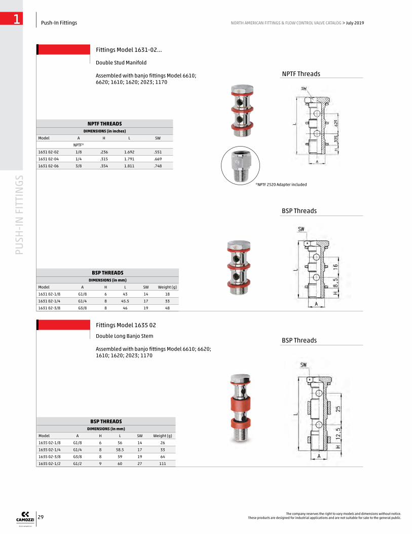
BSP THREADSDIMENSIONS (in mm)
Model A H L SW Weight (g)
1635 02-1/8 G1/8 6 56 14 26
1635 02-1/4 G1/4 8 58.5 17 33
1635 02-3/8 G3/8 8 59 19 64
1635 02-1/2 G1/2 9 60 27 111
BSP THREADSDIMENSIONS (in mm)
Model A H L SW Weight (g)
1631 02-1/8 G1/8 6 43 14 18
1631 02-1/4 G1/4 8 45.5 17 33
1631 02-3/8 G3/8 8 46 19 48
NPTF THREADSDIMENSIONS (in inches)
Model A H L SW
NPTF*
1631 02-02 1/8 .236 1.692 .551
1631 02-04 1/4 .315 1.791 .669
1631 02-06 3/8 .354 1.811 .748
*NPTF 2520 Adapter included
Fittings Model 1631-02...
Double Stud Manifold
Assembled with banjo fittings Model 6610; 6620; 1610; 1620; 2023; 1170
Fittings Model 1635 02
Double Long Banjo Stem Assembled with banjo fittings Model 6610; 6620; 1610; 1620; 2023; 1170
BSP Threads
BSP Threads
NPTF Threads
30
PUSH
-IN F
ITTI
NGS
Push-In Fittings1 NORTH AMERICAN FITTINGS & FLOW CONTROL VALVE CATALOG > July 2019
The company reserves the right to vary models and dimensions without notice.These products are designed for industrial applications and are not suitable for sale to the general public.
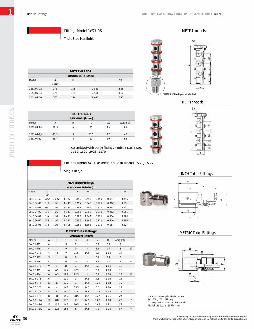
BSP THREADSDIMENSIONS (in mm)
Model A H L SW Weight (g)
1631 03-1/8 G1/8 6 59 14 24
1631 03-1/4 G1/4 8 61.5 17 42
1631 03-3/8 G3/8 8 62 19 62
*NPTF 2520 Adapters included
NPTF THREADSDIMENSIONS (in inches)
Model A H L SW
NPTF*
1631 03-02 1/8 .236 2.322 .551
1631 03-04 1/4 .315 2.421 .669
1631 03-06 3/8 .354 2.440 .748
Fittings Model 1631-03...
Triple Stud Manifolds
Assembled with banjo fittings Model 6610; 6620; 1610; 1620; 2023; 1170
BSP Threads
NPTF Threads
METRIC Tube FittingsDIMENSIONS (in mm)
Model A C F M O V W Weight (g)
6610 4-M5 4 5 9 19 9 5.1 Ø 9 9
6610 4-M6 4 5 9 19 9 5.1 Ø 9 8 ●
6610 4-1/8 4 7.5 9 21.5 14.5 9.8 Ø 14 14
6610 5-M5 5 5 10 20 9 5.1 Ø 9 9
6610 5-M6 5 5 10 20 9 5.1 Ø 9 8 ●
6610 5-1/8 v 8 10 23 14.5 9.8 Ø 14 16
6610 6-M5 6 6.5 12.7 22.5 9 5.1 Ø 10 12
6610 6-M6 6 6.5 12.7 22.5 9 5.1 Ø 10 12 ●
6610 6-1/8 6 8 12.7 24 14.5 9.8 Ø 14 16
6610 6-1/4 6 10 12.7 26 14.5 13.2 Ø 18 19
6610 8-1/8 8 8 14.2 25.5 14.5 9.8 Ø 14 19
6610 8-1/4 8 10 14.2 27.5 14.5 13.2 Ø 18 22
6610 8-3/8 8 11 14.2 28.5 14.5 16.7 Ø 21 23
6610 10-1/4 10 8.8 16.5 29 14.5 13.2 Ø 18 22 *
6610 10-3/8 10 10.3 16.5 30.5 14.5 16.7 Ø 21 23 *
6610 12-1/2 12 12.8 16.5 32 14.5 21 Ø 26 37 *
● = assembly required with Model SCU, SVU, SCO... M5 only * = they cannot be assembled with Model 1631, use 1635 instead
INCH Tube FittingsDIMENSIONS (in inches)
Model A OD
V C F M O V W
6610 53-32 5/32 10-32 0.197 0.346 0.748 0.354 0.197 0.346
6610 02-02 1/8 1/8 0.295 0.354 0.846 0.571 0.382 0.551
6610 53-02 5/32 1/8 0.335 0.394 0.886 0.571 0.382 0.551
6610 04-02 1/4 1/8 0.327 0.500 0.965 0.571 0.382 0.551
6610 04-04 1/4 1/4 0.406 0.500 1.043 0.571 0.516 0.709
6610 06-04 3/8 1/4 0.354 0.650 1.142 0.571 0.516 0.709
6610 06-06 3/8 3/8 0.413 0.650 1.201 0.571 0.657 0.827
Fittings Model 6610 assembled with Model 1631, 1635
Single BanjoINCH Tube Fittings
METRIC Tube Fittings