NICKEL NANOPARTICLES- SYNTHESIS, CHARACTERIZATION AND
44
Chapter I 1 CHAPTER I NICKEL NANOPARTICLES- SYNTHESIS, CHARACTERIZATION AND CATALYTIC APPLICATIONS IN ORGANIC SYNTHESIS: A REVIEW I. INTRODUCTION The past few years have witnessed an exponential growth of interest in areas like nanotechnology, nanoscience and nanomaterials. This interest arises from the fact that at these size regimes, new properties are attained which are size or shape dependent. 1 Nanotechnology is a multidisciplinary field with contribution from physics, chemistry, biology and engineering. Nanotechnology deals with materials having dimensions ranging between one to several hundreds of nanometers (1nm = 10 -9 m). Nanometer sized particles display many interesting optical, electronic, magnetic and chemical properties which have applications in biological nanosensors, optoelectronics, nanodevices, nanoelectronics, information storage and catalysis which differ significantly from that of bulk material. Metal nanoparticles have witnessed a burst in research activities owing to their ease of preparation and remarkable applications in organic synthesis. Though metal nanoparticles of a variety of transition metals like Ni, Pd, Pt, Au, Ag and Cu have been prepared, nanoparticles of Ni and Pd have drawn special interest in organic synthesis. We have reviewed the properties of nanoparticles (I.1), synthesis with focus on Ni nanoparticles (I.2), characterization techniques (I.3) and catalytic applications of nickel nanoparticles (I.4) in this chapter. I.1 PROPERTIES OF NANOPARTICLES I.1.1. Electronic properties The electronic structure of nanoparticles may be considered to be intermediate between the discreet levels of an atom and the continuous band structure of a bulk solid. When bulk metal is reduced in size to a few nanometers, the continuous density
Transcript of NICKEL NANOPARTICLES- SYNTHESIS, CHARACTERIZATION AND

Chapter I
1
CHAPTER I
NICKEL NANOPARTICLES- SYNTHESIS, CHARACTERIZATION AND CATALYTIC APPLICATIONS IN ORGANIC SYNTHESIS:
A REVIEW I. INTRODUCTION The past few years have witnessed an exponential growth of interest in areas like nanotechnology, nanoscience and nanomaterials. This interest arises from the fact that at these size regimes, new properties are attained which are size or shape dependent.1 Nanotechnology is a multidisciplinary field with contribution from physics, chemistry, biology and engineering. Nanotechnology deals with materials having dimensions ranging between one to several hundreds of nanometers (1nm = 10-9m). Nanometer sized particles display many interesting optical, electronic, magnetic and chemical properties which have applications in biological nanosensors, optoelectronics, nanodevices, nanoelectronics, information storage and catalysis which differ significantly from that of bulk material. Metal nanoparticles have witnessed a burst in research activities owing to their ease of preparation and remarkable applications in organic synthesis. Though metal nanoparticles of a variety of transition metals like Ni, Pd, Pt, Au, Ag and Cu have been prepared, nanoparticles of Ni and Pd have drawn special interest in organic synthesis.
We have reviewed the properties of nanoparticles (I.1), synthesis with focus on Ni nanoparticles (I.2), characterization techniques (I.3) and catalytic applications of nickel nanoparticles (I.4) in this chapter. I.1 PROPERTIES OF NANOPARTICLES I.1.1. Electronic properties The electronic structure of nanoparticles may be considered to be intermediate between the discreet levels of an atom and the continuous band structure of a bulk solid. When bulk metal is reduced in size to a few nanometers, the continuous density

Chapter I
2
of states in the conduction band is replaced by a set of discreet energy levels which raises the band gap (the gap between valence band and conduction band) (Fig. I.1). Eventually, a size is reached where the distance between the surfaces of the particles becomes of the order of the wavelength of the electrons. At this point, the energy levels of the nanoparticles may be treated similar to those of a particle in a box. This is referred to as quantum size effect.2-3 The separation between adjacent energy levels increases with decreasing dimensions similar to a particle in a box.
Fig. I.1: Illustration of formation of discreet energy levels in nanoclusters from
continuous band structure of bulk metal. I.1.2. Optical properties One of the most interesting aspects of metal nanoparticles is the dependence of optical properties on size and shape. Bulk gold looks yellowish in reflected light, but thin gold films look blue in transmission. This characteristic blue color steadily changes to orange, through several tones of purple and red, as the particle size is reduced down to ~3 nm. The color exhibited by nanoparticles is due to the coherent excitation of the conduction band electrons induced by interaction with an electromagnetic (EM) field. This resonance is called Surface Plasmon Resonance (SPR).4 The electric field of incident light induces the formation of a dipole in the nanoparticle by causing polarization of free electrons (Fig. I.2). A restoring force is generated by the surface charges, resulting in a unique resonance wavelength. A pre-requisite for such property is the presence of free conduction electrons like in silver, gold and copper.

Chapter I
3
Fig. I.2: Schematic diagram of interaction of electromagnetic radiation with metal
nanorods and metal nanospheres. I.1.3. Magnetic properties Finely divided magnetic nanoparticles are desirable in this emerging field due to their large domains of application, especially in high-density magnetic recording media or magnetically responsive fluids. The magnetic properties of these particles depend crucially on their shape or size.5 Decreasing the particle size leads to a size range, where the particles consist of only a single magnetic domain (Fig. I.3).
Single domain Multidomain HC
Ferromagnetisme Particle Size 2-10nm DC
Superparamagnetism Paramagnetisme
Fig. I.3: Transition from multidomain to single magnetic domain on decreasing the
particle size.
I.1.4. Melting points The melting point of nanosized metal particles depends upon the size of the particles. As particles decrease in size, the number of surface atoms becomes equal to or even exceeds the number of inner-core atoms. For a typical bulk material, the surface is negligibly small in comparison to the total volume. Surface atoms are more easily rearranged than those in the center of the particle, and so the melting process, which

Chapter I
4
depends on destroying the order of the crystal lattice, can get started at a lower temperature. The melting point of gold metal is 1064°C. For 11-12 nm gold particles, melting point is about 1000°C, which drops dramatically to 900°C for 5 to 6 nm particles and to 700°C for 2 to 3 nm particles.6
I.2. SYNTHESIS OF METAL NANOPARTICLES Two approaches, namely, ‘Top-down’ and ‘Bottom-up’, are employed for the synthesis of nanomaterials (Fig. I.4). Top down approach involves division of bulk solid into smaller portions. It includes physical methods like attrition or milling, repeated quenching etc. Bottom-up approach involves condensation of atoms or molecular entities to build up a nanomaterial. It includes chemical methods like reduction of metal salts. The latter approach is far more popular for the synthesis of nanoparticles since it gives a homogeneous size distribution than the former approach.
Fig. I.4: Top-down and Bottom-up approach for nanomaterial synthesis.
I.2.1. Nucleation and growth According to the homogeneous nucleation theory, based on the Lamer model,7 production of monodisperse nanostructures requires a short nucleation event followed

Chapter I
5
by slower controlled growth on the existing nuclei. Rapid addition of reagents to the reaction vessel raises the precursor concentration above the nucleation threshold. The temperature of the system is appropriate to decompose the reagents, resulting in supersaturation of particles in solution. A short nucleation burst results in a drop in concentration of these species below the critical concentration for nucleation (nucleation threshold). As long as the consumption of reactants is not exceeded by the rate of precursor addition to the solution, no new nuclei are formed. Since the growth of nanocrystal is similar, the initial size distribution is determined by the time over which the nuclei are formed and begin to grow. If the time of nanocrystal growth during the nucleation period is short compared to the subsequent growth, size focusing takes place and nanocrystals become more uniform over time. In some systems, Ostwald ripening8 or defocusing is observed where smaller particles get smaller and finally dissolve and larger particles continue to grow by the deposition of additional material. The average nano crystal size increases over time with a compensating decrease in nano crystal number. I.2.2. Stabilization of metal nanoparticles The high surface energy of nanoparticles renders them thermodynamically unstable and highly susceptible to agglomeration due to which catalytic properties of metal nanoparticles are largely affected. At short inter-particle distances, the van der Waals forces show that two metallic particles will be mutually attracted. In the absence of repulsive forces opposed to the van der Waals, the colloidal metal particles will aggregate. Consequently, the use of a protective agent which can induce a repulsive force opposed to the van der Waals forces is necessary to provide stable nanoparticles in solution. The general stabilization mechanisms of colloidal materials have been described in Derjaguin–Landau–Verway–Overbeck (DLVO) theory.9-10
Four types of nanoparticle stabilization are possible: I.2.2.1. Electrostatic stabilization Anions and cations generated by the ionic compounds such as halides, carboxylates and polyoxoanions in solution get adsorbed on the nanoparticle surface thereby

Chapter I
6
developing an electrical double layer around the particles. This results in coulombic repulsion between particles which prevents aggregation (Fig. I.5).
Fig. I.5: Schematic representation of electrostatic stabilization.
I.2.2.2. Steric stabilization
Aggregation of particles may also be prevented by the use of large molecules like polymers or surfactants. The adsorption of these molecules over nanoparticle surface provides a protective layer. High local concentration of stabilizer in the inter-particle space prevents agglomeration (Fig. I.6 (a)). Polyvinyl pyrrolidone (PVP) is one of the most widely used polymer for stabilization of nanoparticles11-12 and catalysis, due to its ability to ligate to the metal surface from its adjacent nitrogen and oxygen atoms which forms the first protective layer while the other part dissolves freely in the suspension, creating a second protective shell as shown in Fig. I.6 (b).13
(a) (b) Fig. I.6: (a) Schematic representation of steric stabilization; (b) PVP stabilization of metal nanoparticles

Chapter I
7
Other polymers like polyethylene glycol, polyvinyl alcohol etc. have also been used to provide protective layers. For example, Mu et al14 used PVP-stabilized Pt, Pd and Rh nps immobilized in an ionic liquid, 1-n-butyl-3-methylimidazolium hexafluorophosphate ([bmim][PF6]) for a variety of organic reactions. I.2.2.3. Electrosteric stabilization Nanoparticles can be effectively protected by combining the electrostatic and steric stabilization,15-16 provided by ionic surfactants. These compounds bear a polar head group capable of generating an electric double layer and a lypophilic side chain to provide steric repulsion. Cationic surfactants like cetyltrimethylammonium bromide (CTAB)17 and anionic surfactants such as sodium dodecyl sulfate (SDS)18 have been found to effectively stabilize the metal nanoparticles. The key concept behind such stabilization is the combined high charge plus significant steric bulk. I.2.2.4. Ligand stabilization Ligands such as thiols,19 phosphines viz. TOPO20 and BINAP,21 amines like polyaniline22 and hexadecylamine,23 CO,24 thioethers25 and oleic acid26 have been used to stabilize transition metal nanoparticles. Polymers like β-cyclodextrin,27 gluten,28 cyclohexyldiamine modified glycidyl methacrylate polymer,29 poly(vinyl alcohol),30 polyethylene glycol31 etc. have been utilized as stabilizers during nanoparticles synthesis. Recently, Liao et al32 have used sodium citrate as complexing agent and stabilizing agent to prepare cobalt nanoparticles. Effect of sodium citrate on the yield, crystal structure, particle size and size distribution of the nano-sized cobalt particles was also studied. I.2.3. Synthesis by chemical reduction The ‘wet chemical reduction’ method discovered by Faraday has become the most commonly used synthetic method for nanoparticles. A wide range of reducing agents such as hydrogen, alcohol, sodium borohydride, hydrazine, sodium citrate etc. have been utilized to obtain nanoparticle dispersion. Synthesis of metal nanoparticles using an aqueous alcohol reduction of a metal precursor was first reported by Hirai et al.33

Chapter I
8
In this process, alcohol acts both as solvent and reducing agent. Generally, alcohols containing α-hydrogen like ethanol, methanol and 2-propanol are useful reducing agents. Boutonett and co-workers34 used H2 reduction to generate various transition metal nanoparticles. Aqueous colloidal solutions of Au, Ag, Ir, Pt, Pd, Rh or Ru were also prepared by H2 reduction of the corresponding chloride salts. Advantage of using hydrogen lies in the avoidance of by-products and the disadvantage is that it is a weak reducing agent and unable to reduce many metal complexes. Polymer stabilized hydrosols of Pd, Pt, Rh and Ir have been successfully synthesized by using hydrogen.35
Reduction of transition metal salts using borohydrides is the most widely used hydride reduction method of generating metal nanoparticle dispersions.36 Superhydride37 and sodium borohydride38 have been effectively used to synthesize well dispersed copper nanoparticles protected by alkanethiolate monolayers and non-ionic surfactant Triton X-100, respectively. Hydrazine has also been efficiently used in the synthesis of metal nanoparticles like Cu (0)39 and Ni (0)17c due to its strong reducing ability. Turkevitch and co-workers studied the nucleation and growth of Au nanoparticles using sodium citrate as the reducing agent.40 In this case, citrate is not only a reducing agent but also an ionic stabilizer. However, citrate anion has some disadvantage because of the simultaneous formation of the intermediate acetone dicarboxylic acid. Other reducing agents used to prepare various metal nanoparticles include DMF,41 sodium formate,42 sodium hypophosphite,43 potassium bi-tartarate44 and sugars (glucose, fructose, sucrose etc.).45
I.2.3.1. Nanoparticle synthesis in microemulsion Oil and water are normally immiscible but with the addition of a surfactant, the oil and water become miscible since the surfactant reduces the interfacial tension between the two fluids. The proportion of the two fluids determines whether water-in-oil (w/o) or oil-in-water (o/w) dispersions are produced. The emulsion thus obtained is turbid and thermodynamically unstable but kinetically stable. Schulman and co-workers46 have observed that in the presence of short chain alkanols, e.g. butanol, pentanol, hexanol, etc., the emulsions transform into solutions that are homogeneous,

Chapter I
9
optically isotropic and thermodynamically stable. This system is called microemulsion.47 The different structures of a microemulsion at a given concentration of surfactant are shown in Fig. I.7.
Fig. I.7: Schematic representation of a microemulsion at a given concentration of
surfactant as function of temperature and water concentration These microemulsions having nanodimensions can be considered as nanoreactors which can be used to carry out chemical reactions and, in particular, to synthesize nanomaterials. The w/o microemulsion is of particular interest since the hydrophilic interior of these droplets can dissolve a certain amount of water-soluble material e.g., transition metal salts and reducing agents. Synthesis of transition metal nanoparticles in a reverse micelle is mainly carried out either by mixing two microemulsions, one containing the precursor salt and other containing the reducing agent in the hydrophilic cores, or by directly adding the reducing agent to the microemulsion containing precursor salt (Fig. I.8.). The size of the final metallic particle will much depend on the size of the droplets in the microemulsion which in turn depends on the water to surfactant ratio, w. As this ratio increases, the size of droplets in reverse micelles will also increase. Lisiecki et al48 reported that an increase in the concentration of Cu nanoparticles prepared in a system consisting of AOT, cyclohexane and water corresponds to an increase in the number of droplets, i.e., a decrease of the average number of copper ions per droplet. A number of studies have shown that the size of the particle is influenced by the size of the droplet. But only the nuclei are formed inside the droplet after reduction and not the final particles. Particle formation proceeds through two steps: nucleation inside the droplet followed by aggregation process. The size of the droplet influences the size of the nuclei but the

Chapter I
10
size of the final particle is controlled by the surrounding surfactant molecules which sterically prevent the growth process. Other factors which influence the particle size include concentration of precursor salt49 and reducing agent.50
Fig. 1.8: Microemulsion based nanoparticles synthesis Boutonett et al first used w/o microemulsion to produce Ag, Pd, Pt and Rh metal clusters by hydrazine or hydrogen reduction.51 Anionic inverse microemulsion systems using AOT and sodium bis(2-ethylhexyl) sulfosuccinate have also been used to stabilize the clusters.52 Reverse micelles have been employed to synthesize Cu, Ni, Pd, Au and Ag nanoparticles using surfactants like Triton X-100,38,53 sodium dodecyl sulphate (SDS), sodium dodecylbenzene sulfonate (SDBS)49 and cetyltrimethylammonium bromide (CTAB).50 The microemulsion technique has also been widely used to prepare wide variety of nanoparticles.54 I.2.3.2. Dendrimer stabilized synthesis of metal nanoparticles The two families of dendrimers used in the nanoparticle synthesis are poly(amidoamine) (PAMAM) and poly(propylene imine) (PPI) dendrimers (Fig. I.9(a)). Dendrimers are particularly well suited for hosting metal nanoparticles for the following reasons: (a) the dendrimer templates themselves are of fairly uniform composition and structure, and therefore, they yield well defined nanoparticle

Chapter I
11
replicas,55 (b) the nanoparticles are stabilized by encapsulation within the dendrimer, and therefore they do not agglomerate, (c) dendrimers prevent aggregation but do not passivate the active sites on the metal surface,56 (d) dendrimer encapsulated nanoparticles are easily recycled via filtration and centrifugation,57 and (e) the terminal groups on the dendrimer periphery can be tailored to control solubility of the hybrid nanocomposites and used as handles for facilitating linking to surfaces and other polymers.58 Dendrimer encapsulated nanoparticles (DENPs) are synthesized by complexing metal ions within dendrimers and then reducing those to zero-valent metal atoms (Fig. I.9(b)).
N N
NH
NO
HNO
NH2
NH
ONH2
O
NO
NH2
NH
ONH2
OHN
N
HNO
NH2
NH
O
H2N
O
HN
NHN
O
H2N
HN
O NH2
G1 PAMAM Dendrimer
NN
N
NH2
NH2
N NH2
NH2
N
NH2
H2N
NH2N
H2N
G1 PPI Dendrimer (a) (b)
(c) Fig. I.9: (a, b) Commonly employed dendrimers; (c) Use of dendrimers during
nanoparticles synthesis

Chapter I
12
Formation of dendrimer stabilized nanoparticles was introduced by Crooks and co-workers.59 Recently, Astruc and co-workers synthesized catalytically active palladium nanoparticles stabilized by sulfonated ‘click’ dendrimers60 and click ferrocenyl dendrimers.61
I.2.3.3. Polyol mediated synthesis Polyol process uses a polyalcohol like ethylene glycol or trimethylene glycol as both solvent and reducing agent. Polyols (for example, polyethyleneglycol) offer interesting properties due to their high dielectric constants. They act as solvents which are able to dissolve inorganic compounds and offer a wide operating temperature range (from 25ºC to boiling point) for preparing inorganic compounds due to their relatively high boiling points. Polyol itself can act as a protective agent to avoid agglomeration. When the zero valent metal is nucleated from the bivalent metal ion at the high boiling point of ethylene glycol, metal particles are surrounded with lone pair of electrons of oxygen of butane-2,3-dione derived from ethylene glycol (eq. 1, 2). The presence of a lone pair of electrons keeps the metal particles separated and therefore, the particle size is regulated and controlled without surfactants.
HOCH2CH2OH CH3CHO + H2O ...(1) 2M+ + 2CH3CHO CH3COCOCH3 + 2M + 2H+ …(2)
A variety of metallic nanoparticles have been prepared by the polyol method such as Ag, Fe, Co, Pt, Ni, Pd, Ru, etc.62 The polyol synthetic procedure has been explored widely for the synthesis of metal nanoparticles since the work by the Fie´vet et al.63 Zarbin et al64 reported the preparation of fcc nickel nanoparticles via a modified polyol route using polyvinyl pyrrolidone (PVP) as a stabilizer and sodium borohydride as the reducing agent. A microwave assisted polyol method has also been reported for the synthesis of Ni nanoparticles in a binary protecting agent system including PVP and dodecylamine (DDA).65 Feldmann and co-workers66 reported a polyol mediated synthesis of nanoscale metal sulfide i.e. MS particles (M= Zn, Cd, Hg).

Chapter I
13
Some specific methods for the synthesis of Ni nanoparticles are described below:
Chen et al have reported the synthesis of nickel nanoparticles in aqueous cationic surfactant solutions by the reduction of nickel chloride with hydrazine in an aqueous solution of cationic surfactants cetyltrimethylammonium bromide/ tetradodecylammonium bromide (CTAB/TC12AB)67 as well as the cationic water-in-oil microemulsions of water/CTAB (cetyltrimethylammonium bromide)/n-hexanol at 73°C (eq. 3).
2Ni2+ + N2H4 + 4OH- 2Ni + N2 + 4H2O …(3)
The resultant particles were characterized to be the pure nickel nanoparticles with a face-centered cubic (fcc) structure by electron diffraction pattern and X-ray diffraction.50 Chemical reduction of nickel salts viz. Ni(CH3COO)2 or Ni(acac-acetylacetonate)2 to prepare Ni nps with six different mean sizes (Fig. I. 10) has also been reported.68
Fig. I.10: TEM images of prepared Ni nanoparticles
A new route for the synthesis of carbon-coated core shell structured nickel nanoparticles has been developed in ionic liquid under microwave heating by Jacob and co-workers.69 They utilized 1-butyl-3-methylimidazolium tetrafluoroborate [bmim]BF4 as the ionic liquid solvent under microwave irradiation. The results of XRD and the HRTEM indicated reduction of metal salts to the metallic state. The presence of the amorphous carbon observed clearly in the HRTEM images suggests that the reduction of the metal ions is, perhaps, assisted by the amorphous carbon. They attributed this to the
Chapter I
14
decomposition of the ionic liquid, which absorbs the MW radiation and reaches its decomposition temperature in the presence of a metal salt within a short period. This was confirmed by the control MW irradiations of the pristine ionic liquid without metal salt leading to its decomposition to yield carbon particles. At this high temperature, once the decomposition occurs, the carbon produced reduces the metallic ions (Fig. I.11).
Fig. I.11: TEM image showing coated Ni nanoparticles
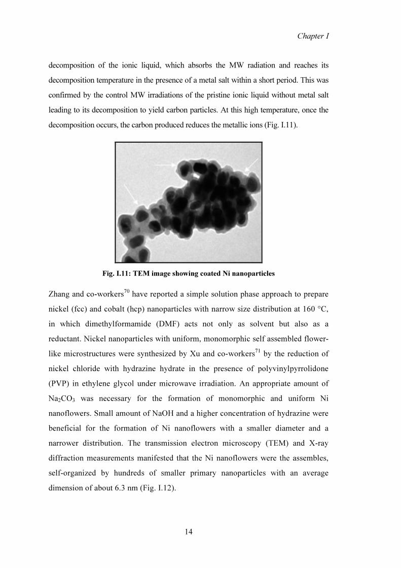
Zhang and co-workers70 have reported a simple solution phase approach to prepare nickel (fcc) and cobalt (hcp) nanoparticles with narrow size distribution at 160 °C, in which dimethylformamide (DMF) acts not only as solvent but also as a reductant. Nickel nanoparticles with uniform, monomorphic self assembled flower-like microstructures were synthesized by Xu and co-workers71 by the reduction of nickel chloride with hydrazine hydrate in the presence of polyvinylpyrrolidone (PVP) in ethylene glycol under microwave irradiation. An appropriate amount of Na2CO3 was necessary for the formation of monomorphic and uniform Ni nanoflowers. Small amount of NaOH and a higher concentration of hydrazine were beneficial for the formation of Ni nanoflowers with a smaller diameter and a narrower distribution. The transmission electron microscopy (TEM) and X-ray diffraction measurements manifested that the Ni nanoflowers were the assembles, self-organized by hundreds of smaller primary nanoparticles with an average dimension of about 6.3 nm (Fig. I.12).
Chapter I
15
Fig. I.12: TEM images of the nanoflowers. The molar ratios of N2H4·H2O/NiCl2 were
2/1, 10/1, 20/1 in (A), (B). In all cases, [NiCl2] = 5 mM; Na2CO3/NiCl2/ NaOH/PVP = 1/1/0.2/40 (molar ratio).
Tzitzios and co-workers26a prepared hexagonal close-packed (hcp) Ni nanoparticles in the range of 13–25 nm by reduction of Ni(NO3)2 in polyethylene glycol (PEG) of varying molecular weights. The reaction occurred in the presence of an equimolecular mixture of oleic acid and oleyl amine, which played the role of a stabilizer and was also responsible for solubility of nanoparticles in non-polar solvents. The crystal structure of Ni particles was controlled by the molecular weight of the PEG and the reaction temperature.
Chen et al72 studied the magnetic properties of nickel nanoparticles which were synthesized by the thermal decomposition of nickel(II) acetylacetonate in alkyl amines (oleyl amine, trioctyl amine, dodecyl amine and hexadecyl amine). The Ni nanoparticles were characterized by powder X-ray diffraction, TEM and magnetic measurement. The alkyl amines served as solvents and reducing agents. Depending on the reaction conditions like temperature, heating rate and solvent type, face-centered cubic (fcc) or hexagonal close-packed (hcp) Ni nanoparticles could be obtained. Monodispersed Ni nanoparticles were also obtained by introducing surfactants (oleic acid and trioctylphosphine) (Fig. I.13).

Chapter I
16
(a) (b) Fig. I.13: (a) TEM image of Ni nanoparticles; (b) XRD pattern of hcp Ni nanoparticles Monodispersed pure nickel nanoparticles in aqueous medium were also prepared using cetyltrimethylammonium bromide and a mixture of tetraethylammonium bromide and tetrabutylammonium bromide.17c The presence of cetyltrimethylammonium bromide alone resulted in the formation of a mixture of nickel hydroxide and nickel nanoparticles. The particle analysis showed that particles were spherical in shape, monodispersed, face centered cubic with average size of about 15 nm and were stable in air up to 325 °C.
Yua et al73 have reported preparation of finely divided nickel powders without agglomeration with rod like shape (Fig. I.14). The ethylene glycol (EG) solution of NiSO4.6H2O and NaOH was reduced with hydrazine hydrate at 80–95 °C (eq. 4-5).
NiSO4 + 2 NaOH Ni(OH)2 + Na2SO4 ...(4)
Ni(OH)2 + 1/2 N2H4 Ni + 1/2 N2 + 2 H2O ...(5) Reaction parameters such as amount of alkali, temperature, reactant concentration, and reduction time were varied for controlling shape, size and agglomeration of the nickel particles. The rod like nickel powders with particle size of 1–8 µm long and 0.1–0.5 µm thick were synthesized.

Chapter I
17
Fig. I.14: SEM micrograph of rod like Ni nanoparticles
Different amounts of nickel were incorporated into the mesopores of MCM-41 via an in situ approach.74 A hydrophobic nickel precursor was incorporated into the nanochannels of mesoporous silica by manipulation of solvent-solute interaction and the results showed the formation of well-ordered hexagonal structure and also established the presence of nickel nanoparticles inside the nanochannels of mesoporous silica.
The nickel nanoparticles with different sizes and spherical shape were also prepared by the reduction of nickel sulfate with sodium borohydride in the water-in-oil emulsions of water/SDBS(sodium dodecylbenzene sulfonate)/n-pentanol/n-heptane.75 The effects of aging time, molar ratio of water to SDBS and the concentration of nickel sulfate were studied on the size of nanoparticles.
Carbon encapsulated nickel nanoparticles with core/shell structure were successfully synthesized with maize derived starch as carbon source and nickel nitrate as metal precursors in flowing hydrogen. These were characterized by SEM, TEM, XRD and vibrating sample magnetometer (VSM). The material was composed of fcc-Ni core and the amorphous carbon shell. The core diameter of the amorphous carbon shell ranged from 30 to 50 nm (Fig. I.15).76

Chapter I
18
(a) (b) Fig. I.15: (a) SEM image of Ni@Cs nanoparticles; (b) TEM image of Ni@Cs nanoparticles. The spherical nickel nanoparticles (~75 nm) were prepared by Fu et al77 by electrical explosion method, and silica was coated on nickel forming complete coverage by the controlled hydrolysis of tetraethyl orthosilicate (TEOS). The method was based on the use of silane coupling agent 3-mercapto propyltrimethoxysilane [HS(CH2)3Si(OCH3)3, MPTS] as a primer to render the nickel surface vitreophilic, thus rendering nickel surface compatible with silica. The thickness of SiO2 coating layer increases with the increasing reaction time. These nickel/silica core–shell nanoparticles can be utilized as precursors for making property tunable magnetic nanoparticles, thin films, and multilayered core–shell structure nanocomposites (Fig. I.16).
NiWire
Electicalexplosion Ni MPTS
Ultrasonicirradiation
Ni S (CH2)3 SiOR
OROR
TEOS,NH4OH + H2OHydrolysis andCondensation
Ni
SiO2
Fig. I.16: Schematic representation of synthesis and use of Ni nanoparticles.
Nickel nanoparticles surface capped with self-assembled monolayer of dodecanethiol were prepared by the controlled reduction of nickel chloride (NiCl2·6H2O) in the presence of varying concentrations of dodecanethiol and hydrazine hydrate as the reductant. Dodecanethiol played a critical role in controlling the radius and

Chapter I
19
dispersibility of the surface capped Ni nanoparticles.78 Surface capped nickel nanoparticles have significantly increased stability and dispersibility and can be used as a kind of novel nanoscale lubricating additives. I.3. NANOPARTICLE CHARACTERIZATION TECHNIQUES A variety of characterization techniques have been employed for determination of size, shape and composition of nanoparticles. I.3.1. X-ray Diffraction (XRD) Waves of wavelength comparable to the crystal lattice spacing are strongly diffracted by nanoparticles. Information such as lattice parameter, crystal structure and particle size can be obtained by analysing the diffraction pattern. Bragg’s equation is used to obtain the lattice parameters:
nλ = 2d sin θ
where, λ is the wavelength of incident radiation, d is the interplanar spacing and θ is the angle made by incident beam with lattice planes. X-ray diffraction requires monochromatic radiations, generated by excitation of K-radiations from a pure metal target and then filtering the beam by interposing a foil which absorbs the β-component of K-radiation. The average crystallite size is evaluated using the Scherrer formula:
a = 0.9λ/B cos θ
where, a is the mean diameter of nanoparticles, λ is the X-ray wavelength, B is the full width of the half maxima (FWHM) of the X-ray peak, and θ is the Bragg’s angle. The XRD patterns of copper and platinum nanoparticles are given in Fig. I.17.

Chapter I
20
(a) (b) Fig. I.17: XRD patterns of (a) copper nanoparticles synthesized at 1400C with an
injection rate of 8mL/min in diethylene glycol in presence of PVP,79 (b) PVP–Pt nanoparticles obtained at various initial concentration ratios of PVP/Pt: PVP (wt%)/Pt (mM) ~ (a) 0.5/1.0, (b) 1.0/1.0, (c) 2.0/1.0 and (d) 4.0/1.044
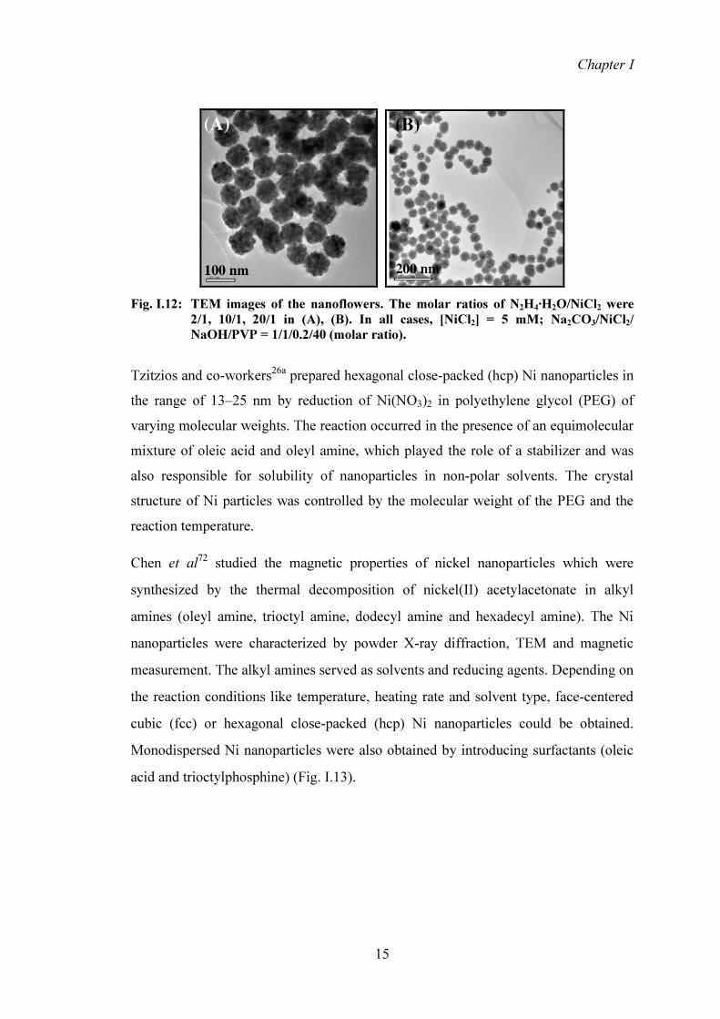
I.3.2. Electron microscopy I.3.2.1. Transmission Electron Microscopy (TEM) TEM is an indispensable technique for characterization of nanocrystal materials, particularly when particle shape is important. In TEM, the incident electron beam is allowed to transmit through a thin sample at a high acceleration voltage. Electron beam is partially transmitted through the sample while part of it is scattered either elastically or non-elastically. Transmission ability is inversely proportional to the thickness. Low atomic-molecular weight materials transmit electrons and appear to be light on the phosphor image screen. Heavy elements interact more strongly with electrons and appear as dark regions on the screen. The darker areas of the image represent those areas of the sample where fewer electrons are transmitted through (thicker or denser areas). The lighter areas of the image represent those areas of the sample where more electrons are transmitted through (thinner or less dense). Fig. I.18 shows the TEM images of nickel and copper nanoparticles.
Chapter I
21
Fig. I.18: (a) TEM images of nickel nanoparticles (25°C, mass ratio of SDBS/n-
pentanol/n- heptane of 4'8'16'35);49 (b) TEM image of copper nanoparticles synthesized at 210 °C in presence of 1,2-hexadecanediol and oleic acid- oleyl amine as reducing agent and capping agent. The enlarged views show (A) cube- (B) tetrahedral- and (C) rod-shaped particles.80
Utilizing a high-voltage electron beam technique, the resolution of transmission electron microscopy is now sufficient to have a clear image of metal nanoparticles at the A° level. This high resolution TEM (HRTEM) provides information not only on the particle size and shape but also on the crystallography of nanoparticles. One of the important secondary effects that are exploited in majority of investigations in TEM is the emission of characteristic X-rays that are element specific (for elemental analysis in EDAX). Energy-dispersive X-ray spectroscopy (EDAX) is used mainly for elemental analysis and for chemical characterization of samples. In EDAX, the incident electron beam excites an electron in an inner shell, causing its ejection and the formation of an electron hole in the electronic structure of the atom. An electron from a higher-energy (outer) shell fills the hole, and the difference in energy between the higher-energy shell and the lower-energy shell is released as X-rays. The X-rays thus released are analyzed by means of an energy-dispersive spectrometer. EDAX systems are commonly found with SEM, as well as with TEM. For example, EDAX has been used to obtain elemental analysis of Au-Ag-alloy nanocrystalline films generated at the liquid-liquid interface. Thus, when energy dispersive X-ray microanalysis (EDAX) is used in conjunction with TEM, localized elemental information can be obtained.81 Fig. I.19 shows the EDAX analysis of cobalt nanoparticles.

Chapter I
22
Fig. I.19: EDAX analysis of cobalt nanoparticles synthesized by microemulsion method
with CTAB as surfactant.17d I.3.2.2. Scanning Electron Microscopy (SEM) If the TEM is operated in scanning mode, it is known as a scanning electron microscope (SEM). The resolution of SEM is not high enough to image individual atoms, but SEM can image larger areas. SEM produces images by focusing a high-energy electron beam onto the surface of the sample, then detecting signals from the interaction of the incident electrons with the sample’s surface. SEM images of copper and palladium nanoparticles are given in Fig. I.20.
(a) (b) Fig. I.20: (a) SEM images of copper particles at 140°C with an injection rate of
2mL/min in diethylene glycol in presence of PVP79 (b) SEM image of the Pd sample prepared with 0.1 mol/L CTAB and 5 mmol/L sodium ascorbate.82

Chapter I
23
I.3.3. Scanning Probe Microscopes (SPM) SPMs are able to image an object’s surface in three dimensions. They provide nanometer scale resolution by using a sharp tip, the probe, which touches or nearly touches a sample’s surface to create images or measure the properties of materials. I.3.3.1. Scanning Tunneling Microscopy (STM) Scanning Tunneling Microscopy (STM) is a technique for viewing surfaces at the atomic level and is useful for obtaining information about the electronic states and the morphology of nanomaterials of different dimensionalities. The electron cloud associated with metal atoms at a surface extends a very small distance above the surface. When a conducting probe is brought close to the sample, there is a strong interaction between the electron cloud on the surface and that of the tip and an electric tunneling current flow between them. The tunneling current rapidly increases as the distance between the tip and the surface decreases. Variations in the current as the probe passes over the surface are transformed into an image. I.3.3.2. Atomic Force Microscopy (AFM) The instrument measures forces on a surface by scanning the sample with the tip attached to a flexible cantilever. The AFM technique relies on a balance between the probe tip and the surface. AFM provides real topographical images of sample surfaces. In a typical AFM setup, the deflection of a microfabricated cantilever with a sharp tip is measured by reflecting a laser beam from the back side of the cantilever as it scans over the surface of the sample. There are three major modes of operation namely, contact mode, non-contact mode and tapping mode (Fig. I.21).
(a) (b) Fig. I.21: Modes of AFM operation: (a) Non-contact and Contact mode (b) Tapping mode
Chapter I
24
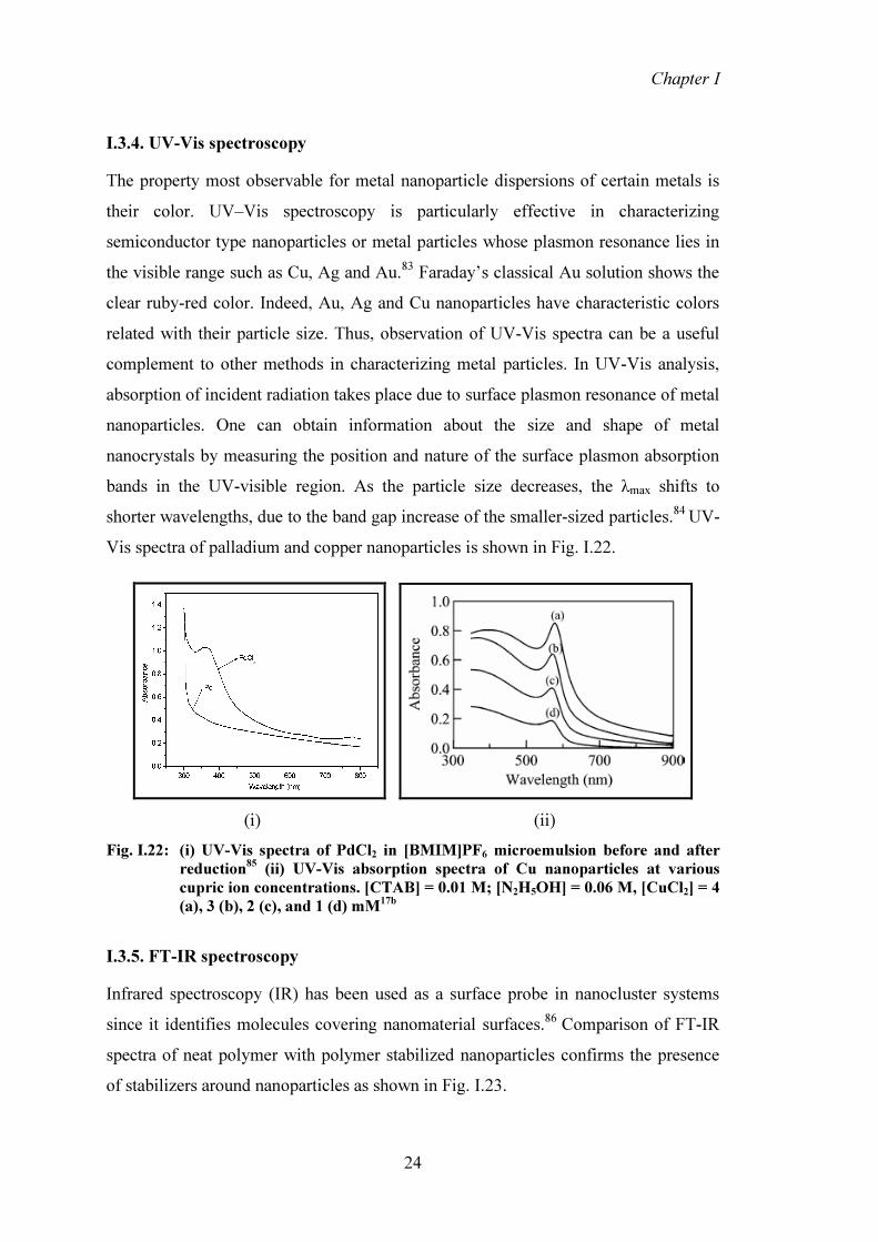
I.3.4. UV-Vis spectroscopy The property most observable for metal nanoparticle dispersions of certain metals is their color. UV–Vis spectroscopy is particularly effective in characterizing semiconductor type nanoparticles or metal particles whose plasmon resonance lies in the visible range such as Cu, Ag and Au.83 Faraday’s classical Au solution shows the clear ruby-red color. Indeed, Au, Ag and Cu nanoparticles have characteristic colors related with their particle size. Thus, observation of UV-Vis spectra can be a useful complement to other methods in characterizing metal particles. In UV-Vis analysis, absorption of incident radiation takes place due to surface plasmon resonance of metal nanoparticles. One can obtain information about the size and shape of metal nanocrystals by measuring the position and nature of the surface plasmon absorption bands in the UV-visible region. As the particle size decreases, the λmax shifts to shorter wavelengths, due to the band gap increase of the smaller-sized particles.84 UV-Vis spectra of palladium and copper nanoparticles is shown in Fig. I.22.
(i) (ii) Fig. I.22: (i) UV-Vis spectra of PdCl2 in [BMIM]PF6 microemulsion before and after
reduction85 (ii) UV-Vis absorption spectra of Cu nanoparticles at various cupric ion concentrations. [CTAB] = 0.01 M; [N2H5OH] = 0.06 M, [CuCl2] = 4 (a), 3 (b), 2 (c), and 1 (d) mM17b
I.3.5. FT-IR spectroscopy Infrared spectroscopy (IR) has been used as a surface probe in nanocluster systems since it identifies molecules covering nanomaterial surfaces.86 Comparison of FT-IR spectra of neat polymer with polymer stabilized nanoparticles confirms the presence of stabilizers around nanoparticles as shown in Fig. I.23.

Chapter I
25
Fig. I.23: Infrared spectra of the samples: (a) neat PVP; (b) Ni-PVP-1/10; (c) Ni-PVP-
1/5; (d) Ni-PVP-1/1; (e) Ni-PVP-1/0.5; (f) Ni-PVP-1/0.1; (g) non-PVP-Ni.64 I.4. CATALYTIC APPLICATIONS OF METAL NANOPARTICLES
There has been tremendous interest in investigating applications of metal nanoparticles in organic synthesis. Metal nanoparticles have drawn special interest in this regard because of the fact that numerous reactions are catalyzed by metals. One of the major reasons is the high surface-to-volume ratios of metal nanoparticles which makes them promising materials for catalysis. Industries usually make use of heterogeneous catalysis, that benefits from easy removal of catalyst materials and possible use of high temperatures, but suffers from lack of selectivity. Homogeneous catalysis is very efficient and selective, and is superior from recyclability viewpoint, but it suffers from the difficulty of removal of the catalyst from the reaction media and its limited thermal stability.
Green catalysis aspects require that environmentally benign catalysts be designed for easy removal from the reaction media and are recyclable with high efficiency. Transition metal nanoparticles bridge the gap between these two approaches and therefore, are sometimes called “semi-heterogeneous”. These nanoparticles mimic metal surface activation and catalysis at the nanoscale and thereby bring selectivity and efficiency to heterogeneous catalysis. Nanoparticles themselves can be used as catalysts in homogeneous systems or alternatively they can be heterogenized by fixation onto heterogeneous supports such as silica, alumina, other oxides, carbon

Chapter I
26
nanotubes, etc. The catalytic activity of metal nanoparticles depends on their size and shape, which in turn are influenced by the method of preparation, stabilizer concentration, etc. Nanoparticles may undergo aggregation and suffer from poisoning under the reactions conditions resulting in deactivation and loss of catalytic activity. Therefore, porous materials such as rocks, clays, ceramics, metal oxides, carbonaceous materials are used as supports to immobilize nanoparticles to prevent deactivation and loss of activity.87 Recently, catalytic properties of nanoparticles supported on metal oxides, such as Si,88 Al,89 Ti,90 Ca91 and Mg92 have been reported. Despite, the large variety of supports, the majority of them involve some form of silica. Other supports include sepiolite,93 Montmorillonite-K10 clay94 and polysilanes.95 Immobilization of Pd nanoparticles on solid surface such as molecular sieves was achieved by using the ionic liquid 1,1,3,3-tetramethylguanidinium lactate. This system was used for solvent free hydrogenation of alkenes and showed high activity and stability.96
Ionic liquids (ILs) are valuable media for catalysis with nanoparticles as they can function both as stabilizers and as solvents. Normally, these can be reused several times without any significant loss in catalytic activity as was observed with IL-dispersed Ir, Rh, Pt, Pd and Ru nps. However, in the reactions of aromatic compounds and ketones, some metal nps tend to aggregate.97 Nanoparticles are more stable in the hydrogenation reactions when dispersed in ILs than under solvent free conditions. Pd nanoparticles in ‘classical’ ILs such as [bmim][PF6], tend to agglomerate after the hydrogenation of alkenes.98 However, phenanthroline-protected Pd nanoparticles in this IL are very active and selective in olefin hydrogenation, and the nanoparticle-ionic liquid system can be reused several times without losing activity.99 Pd nanoparticles dispersed in IL have been used as active catalysts in hydrogenation of alkynes,100 dienes,101 alkenes and arenes,102 as well as for Suzuki,103 Heck104 and Stille coupling.105 Cu nanoparticles synthesized in ionic liquids [bmim][BF4] and [bmim][PF6] by Mu et al showed excellent catalytic activity toward 1,3-dipolar cycloaddition between aryl and sugar based terminal alkynes and azides.14 Recently, a variety of reviews on preparation and catalytic applications of metal nanoparticles in ionic liquids have been published.106 We have

Chapter I
27
briefly reviewed below, reactions which have been catalyzed by nickel nanoparticles.
I.4.1. Ni nanoparticles catalyzed reactions
Reactions Reference
I.4.1.1. Hydrogenations
H2Ni/ SiO2 CH3CH3 107H2C = CH2
NiCl2-Li-DTBB(cat.)-ROH
THF, rt R1 R2 108R1 R2
Ni(0) nanoparticles - H2
NiCl2-Li-DTBB(cat.)-ROH
diene alkene
R1 R2
R1 R2
R1 R2
109
R1C CR2
R1C CR2 R1CH=CHR2
OH
O2N
OH
H2NNi nps 110
NO2 NH2Ni - Al2O3 , dense phase CO2
Pd coated Ni nps, 27oC, 1 atm H2
111or
R1 R2
O
R1 R2
OHNi nps
i-PrOH, 76oCR1= aryl, alkyl; R2= H, alkyl, vinyl; R1= R2= cycloalkyl
112
Chapter I
28
Reference
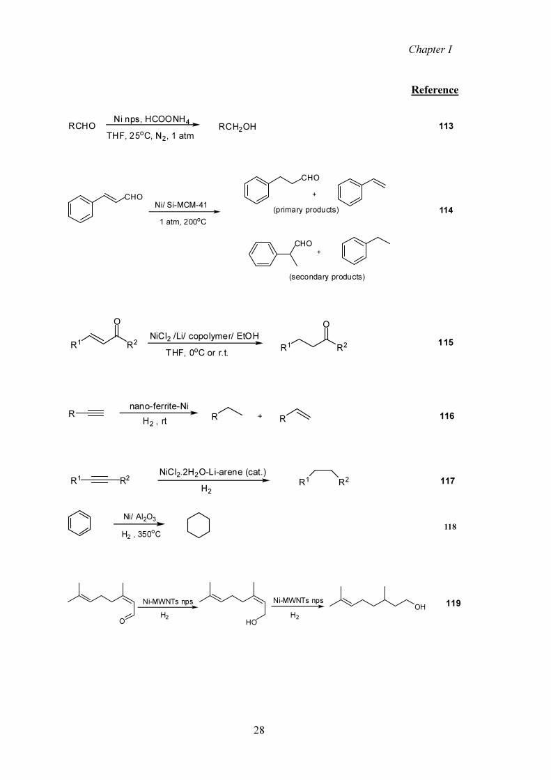
RCHO RCH2OHNi nps, HCOONH4
THF, 25oC, N2, 1 atm113
CHO
CHO
CHO
(primary products)
(secondary products)
1 atm, 200oCNi/ Si-MCM-41 114
R1 R2
ONiCl2 /Li/ copolymer/ EtOH
THF, 0oC or r.t. R1 R2
O115
nano-ferrite-NiH2 , rt R R 116R
NiCl2.2H2O-Li-arene (cat.)H2
117R1 R2 R1 R2
Ni/ Al2O3
H2 , 350oC118
119
O
Ni-MWNTs npsH2 HO
OHNi-MWNTs npsH2

Chapter I
29
Reference
120O
Ph Ni nps , H2OHPh
121
(X= CH, N)
Ar
O
R
HAr
Ni(0)-K10 ClayEtOH
Ar
O
R
ArCH2CH3
Ni(0)-K10 ClayEtOH
Ni(0)-K10 ClayEtOH
121
121ArX=CHR ArXHCH2R
I.4.1.2. Oxidations
SH
OHCH3CN, rt
S 122+ Ni nps
ClBr CN
Ni cat.glyme, 85oC
CN123
ethyl benzene, H2O2O
124Ni nps
I.4.1.3. Coupling
Suzuki coupling
Br
R(R = COCH3, Alkyl)
B(OH)2RNi nps, DMSO, 1350C
Ni/C, R2PPh, LiBr, Dioxaneor
125

Chapter I
30
Reference
Heck reaction
X
R WNi nps, TBAB, K2CO3
hydrothermal
W
R126+
Negishi coupling
Cl
CN
ClZn5% Ni/C, Ph3PTHF, 60oC, 16h
127
CN Kumada coupling
Cl
R
R'MgX, Ni/CPh3P, THF, heat
R'
R
128
Mizoroki Heck
PhI R Ni-SiO2 dopedCH3CN, 47 h Ph
R 129
Thiol coupling
R SH Ni nps (x mol%, 15-18 nm)CH3CN, rt R
S SR
R= aliphatic, aromatic, cyclic, heterocyclic
130
I.4.1.4. Wittig type olefination
Ph OH Ph3P Ph Ni cat.THF, ref lux Ph
Ph131

Chapter I
31
Reference
I.4.1.5. Indirect Aza-Wittig
132R OH
R'COMeNi nps, THF
Ph3P=NPhNi nps, THF
R'
O
R
R NHPh
133R' R' PhCHO R2NH Me2ZnNi nps R'
Me
R'Ph
NR22
I.4.1.6. α-Alkylation of ketones
Ph
OEtOH Ni nps
Ph Ph
OHO
THF134
I.4.1.7. Condensation
135NH2
NH2R
O
O
Ni nps, N2solvent, r.t. N
N
R
136ArCHOHS
HS
Ni npsCH3CN, N2 S
SAr
I.4.1.8. Combinatorial Reactions
137ArCHOO O O
OEt
O
NH
OCOOEt
Ar
Ni npsNH4OAc, MW

Chapter I
32
We have reviewed above the unique properties exhibited by metal nanoparticles, different methods for the synthesis of nanoparticles and stabilization protocols with focus on Ni nanoparticles followed by discussion on variety of characterization techniques including XRD, TEM, SEM, EDAX, STM, AFM, UV-Vis and FT-IR spectroscopy. The catalytic applications of metal nanoparticles have been summarized with focus on catalysis by supported metal nanoparticles which provide the combined benefits of heterogenous and homogenous catalysis.

Chapter I
33
I.5. REFERENCES
1. H.G. Vicki, J. Phys. Chem. C, 112, 18303 (2008).
2. F. Caruso, Colloid and Colloid Assemblies; Wiley-VCH: Weinheim, Germany, (2004).
3. G. Cao, Nanostructures and Nanomaterials: Synthesis, Properties and Applications; Imperial College Press: London, U.K., (2004).
4. U. Kreibig and M. Vollmer, Optical Properties of Metal Clusters, Springer-Verlag, Berlin, (1996).
5. M.L. Billas, I.A. Chatelain and W.A. de Heer, Science, 265, 1682 (1994).
6. K. Klabunde, Nanoscale Materials in Chemistry, Wiley Interscience: New York, 23 (2001).
7. V.K. Lamer and R.H. Dinegar, J. Am. Chem. Soc., 72, 4847 (1950).
8. Y.D. Smet, L. Deriemaeker and R. Finsy, Langmuir, 13, 6884 (1997).
9. J.T.G. Overbeck and J.W. Goodwin, Colloidal Dispersions. Royal Society of Chemistry, London, 1(1981).
10. D.F. Evans and H. Wennerström, The Colloidal Domain, 2nd Edition, Wiley-VCH, New York, (1999).
11. M.L.C.E. Hoppe, I. Pardinas-Blanco and M.A. L´opez-Quintela, Langmuir, 22, 7027 (2006).
12. I. Washio, Y. Xiong, Y. Yin and Y. Xia, Adv. Mater., 18, 1745 (2006).
13. L. Dur´an Pach´on and G. Rothenberg, Appl. Organometal. Chem., 22, 288 (2008).
14. X. Mu, D.G. Evans and Y. Kou, Catal. Lett., 97, 151 (2004).
15. J.D. Aiken III, Y. Lin and R.G. Finke, J. Mol. Catal. A: Chem., 114, 29 (1996).
16. Y. Lin and R.G. Finke, J. Am. Chem. Soc., 116, 8335 (1994).

Chapter I
34
17. (a) S.H. Wu and D.H. Chen, Chem. Lett., 33, 406 (2004); (b) S.H. Wu and D.H. Chen, J. Coll. Interfc. Sci., 273, 165 (2004); (c) M.L. Singla, A. Negi, V. Mahajan, K.C. Singh and D.V.S. Jain, Appl. Catal. A: Gen., 323, 51 (2007); (d) J. Ahmed, S. Sharma, K.V. Ramanujachary, S.E. Lofland and A.K. Ganguli, J. Coll. Interfc. Sci., 336, 814 (2009).
18. I. Lisiecki, F. Billoudet and M.P. Pileni, J. Phys. Chem., 100, 4160 (1996).
19. (a) F. Dassenoy, K. Philippot, T. Ould Ely, C. Amiens, P. Lecante, E. Snoeck, A. Mosset, M.J. Casanove and B. Chaudret, New J. Chem., 22, 703 (1998); (b) S. Chen and K. Kimura, J. Phys. Chem. B, 105, 5397 (2001); (c) K.S. Kim, D. Demberelnyamba and H. Lee, Langmuir, 20, 556 (2004).
20. (a) D.P. Dinega and M.G. Bawendi, Angew. Chem., Int. Ed., 38, 1788 (1999); (b) M. Green and P. O’Brien, Chem. Commun., 1912 (2001).
21. R. Tatumi, T. Akita and H. Fujihara, Chem. Commun., 31, 3349 (2006).
22. K. Mallick, M.J. Witcomb and M.S. Scurrell, J. Mater. Sci., 41, 6189 (2006).
23. (a) H. Wang, X. Jiao and D. Chen, J. Phys. Chem. C, 112, 18793 (2008); (b) Y. Hou, H. Kondoh, T. Ohtab and S. Gao, Appl. Surf. Sci., 241, 218 (2005).
24. A. Rodriguez, C. Amiens, B. Chaudret, M.J. Casanove, P. Lecante and J.S. Bradley, Chem. Mater., 8, 1978 (1996).
25. M. Ganesan, R.G. Freemantle and S.O. Obare, Chem. Mater., 19, 3464 (2007).
26. (a) V. Tzitzios, G. Basina, M. Gjoka, V. Alexandrakis, V. Georgakilas, D. Niarchos, N. Boukos and D. Petridis, Nanotechnology, 17, 3750 (2006); (b) C.W. Kim, H.G. Cha, Y.H. Kim, A.P. Jadhav, E.S. Ji, D.I. Kang and Y.S. Kang, J. Phys. Chem. C, 113, 5081 (2009).
27. L. Strimbu and A. Kaifer, 224th ACS National Meeting, Boston, MA, USA, (2002), COLL-126.
28. Z. Ruimin, W. Xinfeng, H. Xufeng, Z. Fei, L. Hongbin and R. Weihong, Nucl. Instr. Meth. Phys. Res. B, 266, 599 (2008).

Chapter I
35
29. A.M. Trzeciak, E. Mieczynska, J.J. Ziolkowski, W. Bukowski, A. Bukowska, J. Noworol and J. Okal, New J. Chem., 32, 1124 (2008).
30. H. Hirai, Y. Nakao and N. Toshima, Chem. Lett., 905 (1976).
31. G. Linfeng and J.M. Catherine, J. Mater. Chem., 14, 735 (2004).
32. H. Zhu, H. Li, H. Song and S. Liao, Front. Chem. China, 4, 154 (2009).
33. H. Hirai, Y. Nakao and N. Toshima, J. Macromol. Sci., Chem. A, 12, 1117 (1978).
34. (a) M. Boutonett, J. Kizling, P. Stenius and G. Maire, Colloids Surf., 5, 209 (1982); (b) M. Boutonett, J. Kizling, R. Touroude, G. Maire and P. Stenius, Appl. Catal., 20, 163 (1986).
35. (a) L.D. Rampino and F.F. Nord, J. Am. Chem. Soc., 63, 2745 (1941); (b) L.D. Rampino and F.F. Nord, J. Am. Chem. Soc., 65, 2121 (1943); (c) L. Hernandez and F.F. Nord, J. Colloid. Sci., 3, 363 (1948); (d) W.P. Dunsworth and F.F. Nord, J. Am. Chem. Soc. (1950), 72, 4197.
36. I.D. Dragieva and Z.B. Stoynov, Scripta. Mater., 44, 2187 (2001).
37. S. Chen and J.M. Sommersand, J. Phys. Chem. B, 105, 8816 (2001).
38. L. Qi, J. Ma and J. Shen, J. Coll. Interfc. Sci., 186, 498 (1997).
39. H.H. Huang, F.Q. Yan, Y.M. Kek, C.H. Chew, G.Q. Xu, W. Ji, P.S. Oh and S.H. Tang, Langmuir, 13, 172 (1997).
40. J. Turkevitch, P.C. Stevenson and J. Hillier, Discuss. Faraday Soc., 11, 55 (1951).
41. I. Pastoriza-Santos and L.M. Liz-Marza´n, Langmuir, 15, 948 (1999).
42. H. Li and S. Liao, Solid State Commun., 145, 118 (2008).
43. Y. Lee, J. Choi, K.J. Lee, N.E. Stott and D. Kim, Nanotechnology, 19, 7 (2008).
44. Y. Tan, X. Dai, Y. Li and D. Zhu, J. Mater. Chem., 13, 1069 (2003).

Chapter I
36
45. S. Panigradi, S. Kundu, S.K. Ghosh, S. Nath and T. Pal, J. Nanoparticl. Res., 6, 411 (2004).
46. T.P. Hoar and J.H. Schulman, Nature, 152, 102 (1943). 47. M.J. Schwuger and K. Stickdorn, Chem. Rev., 95, 849 (1995). 48. I. Lisiecki and M.P. Pileni, J. Am. Chem. Soc., 115, 3887 (1993). 49. Z. You-Xian, F. Wen-Jie and A. Xue-Qin, Trans. Nonferrous. Met. Soc.
China., 18, 212 (2008). 50. D.H. Chen and S.H. Wu, Chem. Mater., 12, 1354 (2000). 51. M. Boutennet, J. Kizling, V. Mintsa-Eya, A. Choplin, R. Touroude, G. Maire
and P. Stenius, J. Catal., 103, 95 (1987). 52. (a) P. Calandra, C. Giodano, A. Longo and V.T. Liveri, Mater. Chem. Phys.,
98, 494 (2006); (b) M.P. Pileni, B. Hickel, C. Ferradini and J. Pucheault, Chem. Phys. Lett., 92, 308 (1982); (c) A. Taleb, C. Petit and M.P. Pileni, Chem. Mater., 9, 950 (1997); (d) G.X. Cheng, F. Shen, L.F. Yang, L.R. Ma, Y. Tang, K.D. Yao and P.C. Sun, Mater. Chem. Phys., 56, 97 (1998).
53. (a) M.H. Lee, S.G. Oh, K.D. Suh, D.G. Kim and D. Sohn, D, Colloid. Surf. A: Physicochem. Eng. Aspects, 210, 49 (2002); (b) A. Pal, S. Shah and S. Devi, Colloid. Surf. A: Physicochem. Eng. Aspects, 302, 483 (2007).
54. (a) P. Lianos and J.K. Thomas, J. Colloid. Interfc. Sci., 117, 505 (1987); (b) A.R. Kortan, R. Hull, R.L. Opila, M.G. Bawendi, M.L. Steigerwald, P.J. Carroll and L.E. Brus, J. Am. Chem. Soc., 112, 1327 (1990); (c) A.J.I. Ward, E.C. O’Sullivan, J.C. Rang, J. Nedeljkovic and R.C. Patel, J. Colloid Interfc. Sci., 161, 316 (1993); (d) S.K. Haram, A.R. Mahadeshwar and S.G. Dixit, J. Phys. Chem., 100, 5868 (1996); (e) J. Nagy, Colloids Surf., 35, 201 (1989); (f) K. Kandori, K. Kon-No and A. Kitahara, J. Colloid Interfc. Sci., 122, 78 (1988); (g) K. Osseo-Asare and F. Arriagada, J. Colloids Surf., 50, 321 (1990); (h) E. Joselevich and I. Willner, J. Phys. Chem., 98, 7628 (1994); (i) V. Chhabra, M. Lal, A.N. Maitra and P. Ayyub, Colloid. Polym. Sci., 273, 939 (1995); (j) C.L. Chang and H.S. Fogler, Langmuir, 13, 3295 (1997).

Chapter I
37
55. (a) M. Zhao, L. Sun and R.M. Crooks, J. Am. Chem. Soc., 120, 4877 (1998); (b) M. Zhao and R.M. Crooks, Chem. Mater., 11, 3379 (1999).
56. (a) M. Zhao and R.M. Crooks, Angew. Chem., Int. Ed., 38, 364 (1999); (b) M. Zhao and R.M. Crooks, Adv. Mater., 11, 217 (1999); (c) V. Chechik and R.M. Crooks, J. Am. Chem. Soc., 122, 1243 (2000).
57. (a) L.K. Yeung and R.M. Crooks, Nano Lett., 1, 14 (2001); (b) R.W.J. Scott, H. Ye, R.R. Henriquez and R.M. Crooks, Chem. Mater., 15, 3873 (2003).
58. (a) H. Tokuhisa, M. Zhao, L.A. Baker, V.T. Phan, D.L. Dermody, M.E. Garcia, R.F. Peez, R.M. Crooks and T.M. Mayer, J. Am. Chem. Soc., 120, 4492 (1998); (b) H. Tokuhisa and R.M. Crooks, Langmuir, 13, 5608 (1997).
59. (a) Y. Niu, L.K. Yeung and R.M. Crooks, J. Am. Chem. Soc., 123, 6840 (2001); (b) V. Chechik, M. Zhao and R.M. Crooks, J. Am. Chem. Soc., 121, 4910 (1999); (c) L.K. Yeung, C.T. Lee Jr., K.P. Johnston and R.M. Crooks, Chem. Commun., 2290 (2001); (d) R.M. Crooks, M. Zhao, L. Sun, V. Chechik and L.K. Yeung, Acc. Chem. Res., 34, 181 (2001); (e) R.W. Scott, A.F. Datye and R.M. Crooks, J. Am. Chem. Soc., 125, 3708 (2003); (f) R.W. Scott, O.M. Wilson, S.K. Oh, E.A. Kenik and R.M. Crooks, J. Am. Chem. Soc., 126, 15583 (2004).
60. C. Ornelas, J. Ruiz, L. Salmon and D. Astruc, Adv. Synth. Catal., 350, 837 (2008).
61. C. Ornelas, J. Ruiz Aranzaes, E. Cloutet, S. Alves and D. Astruc, Angew. Chem., Int. Ed., 46, 872 (2007).
62. (a) F. Fievet, J.P. Lagier and M. Figlarz, Mater. Res. Bull., 29, 32 (1989); (b) Y. Sun, Y. Yin, B.T. Mayers, T. Herricks and Y. Xia, Chem. Mater., 14, 4736 (2002); (c) L.K. Kurihara, G.M. Chow and P.E. Schoen, Nanostruct. Mater., 5, 607 (1995); (d) L.C. Varanda and M. Jafellici Jr., J. Am. Chem. Soc., 128, 11062 (2006); (e) S. Sun, C.B. Murray, D. Weller, L. Folbes and A. Moser, Science, 287, 1989 (2000); (f) R. Harpeness and A. Gedaken, Langmuir, 20, 3431 (2004).

Chapter I
38
63. (a) G. Viau, F. Fie´vet-Vincent and F. Fie´vet, Solid State Ionics, 84, 259 (1996); (b) L. Poul, N. Jouini and F. Fie´vet, Chem. Mater., 12, 3123 (2000); (c) F. Fie´vet, J.P. Lagier and B. Blin, Solid State Ionics, 198, 32 (1989); (d) F. Fie´vet, F. Vicent, J.P. Lagier and B. Dumont, J. Mater. Chem., 3, 627 (1993).
64. G.G. Couto, J.J. Klein, W.H. Schreiner, D.H. Mosca, A.J.A. de Oliveira and A.J.G. Zarbin, J. Coll. Interfc. Sci., 311, 461 (2007).
65. D. Li and S. Komarneni, J. Am. Ceram. Soc., 89, 1510 (2006).
66. C. Feldmann and C. Metzmacher, J. Mater. Chem., 11, 2603 (2001).
67. D.H. Chen and C.H. Hsieh, J. Mater. Chem., 12, 2412 (2002).
68. (a) S.U. Son, Y. Jang, J. Park, H.B. Na, H.M. Park, H.J. Yun, J. Lee and T. Hyeon, J. Am. Chem. Soc., 126, 5026 (2004); (b) H. Winnischofer, T.C.R. Rocha, W.C. Nunes, L.M. Socolovsky, M. Knobel and D. Zanchet ACS Nano, 2, 1313 (2008).
69. D.S. Jacob, I. Genish, L. Klein and A. Gedanken, J. Phys. Chem. B, 110, 17711 (2006).
70. Z. Zhang, X. Chen, X. Zhang and C. Shi, Solid State Commun., 139, 403 (2006).
71. W. Xu, K.Y. Liew, H. Liu, T. Huang, C. Sun and Y. Zhao, Mater. Lett., 62, 2571 (2008).
72. Y. Chen, D.L. Peng, D. Lin and X. Luo, Nanotechnology, 18, 1 (2007).
73. K. Yua, D.J. Kimb, H.S. Chungb and H. Liang, Mater. Lett., 57, 3992 (2003).
74. A.S. Maybodi, M. Teymouri and A. Vahid, J. Hazard. Mater. doi:10.1016/j.jhazmat.2011.06.089.
75. Y. X. Zhang, W.J. Fu and X.Q. An, Trans. Nonferrous Met. Soc. China, 18 212 (2008).
76. C. Yua and J.S. Qiu, Chem. Engineer. Res. Des., 86, 904 (2008).

Chapter I
39
77. W. Fu, H. Yang, L. Chang, M. Li, H. Bala, Q. Yu and G. Zou, Coll. Surf. A: Physicochem. Eng. Aspects, 262, 71 (2005).
78. L. Chen, J. Chen, H. Zhou, D. Zhang and H. Wan, Mater. Sci. Engineer. A, 452, 262 (2007).
79. B.K. Park, S. Jeong, D. Kim, J. Moon, S. Lim and J.S. Kim, J. Coll. Interfc. Sci., 311, 417 (2007).
80. D. Mott, J. Galkowski, L. Wang, J. Luo and C. Zhong, Langmuir, 23, 5740 (2007).
81. (a) G. Schmid, A. Lehnert, J.O. Malm and J.O. Bovin, Angew. Chem., Int. Ed. Engl., 30, 874 (1991); (b) M. Harada, K. Asakura and N. Toshima, J. Phys. Chem., 98, 2653 (1994).
82. X.S. Shen, G.Z. Wang, X.H. Hong and W. Zhu, Chin. J. Chem. Phys., 22, 440 (2009).
83. J.A. Creighton and D.G. Eadon, J. Chem. Soc., Faraday Trans., 87, 3881 (1991).
84. (a) J.P. Wilcoxon, R.L. Williamson and R. Baughman, J. Chem. Phys., 98, 9933 (1993); (b) J.P. Wilcoxon, P.P. Newcomer and G.A. Samara, J. Appl. Phys., 81, 7934 (1997).
85. G. Zhang, H. Zhou, J. Hu, M. Liu and Y. Kuang, Green Chem., 11, 1428 (2009).
86. E.N. Kaufmann, Characterization of Materials, Hoboken, NJ, Wiley 2 (2003).
87. O.P.H. Vaughan, G. Kyriakou, N. Macleod, M. Tikhov and R.M. Lambert, J. Catal., 236, 401 (2005).
88. (a) R.J. White, R. Luque, V.L. Budarin, J.H. Clark and D.J. Macquarrie, Chem. Soc. Rev., 38, 481 (2009); (b) H.F. Lang, R.A. May, B.L. Iversen and B.D. Chandler, J. Am. Chem. Soc., 125, 14832 (2003); (c) H.F. Lang, S. Maldonado, K.J. Stevenson and B.D. Chandler, J. Am. Chem. Soc., 126, 12949 (2004).
89. (a) A. Molnar, A. Papp, K. Miklos and P. Forgo, Chem. Commun., 2626 (2003); (b) T. Sanji, Y. Ogawa, Y. Nakatsuka, M. Tanaka and H. Sakurai, Chem. Lett., 32, 980

Chapter I
40
(2003); (c) O. Dominguez-Quintero, S. Martinez, Y. Henriquez, L.D.A. Ornelas, H. Krentzien and J. Osuna, J. Mol. Catal. A, 197, 185 (2003); (d) I. Yuranov, P. Moeckli, E. Suvorova, P. Buffat, L. Kiwi-Minsker and A. Renken, J. Mol. Catal. A, 192, 239 (2003); (e) B. Corain, P. Guerriero, G. Schiavon, M. Zapparoli and M. Kralik, J. Mol. Catal. A, 211, 237 (2004); (f) P. Canton, Catal. Lett., 88, 14 (2003); (g) V. Johanek, Surf. Sci., 561, 218 (2004); (h) R.B. Bedford, U.G. Singh, R.I. Walton, R.T. Williams and S.A. Davis, Chem. Mater., 17, 701 (2005).
90. (a) M. Yashima, L.K.L. Falk, A.E.C. Palmqvist and K. Holmberg, J. Colloid Interfc. Sci., 268, 348 (2003); (b) S. Schauermann, J. Hoffmann, V. Johanek, J. Hartmann, J. Libuda and H.J. Freund, Angew. Chem., 114, 2643 (2002); (c) M. Heemeier, A.F. Carlsson, M. Naschitzki, M. Schmal, M.M. Sumer and H.J. Freund, Angew. Chem. Int. Ed., 41, 4073 (2002).
91. (a) K. Ebitani, Y. Fujie and K. Kaneda, Langmuir, 15, 190 (1999); (b) K.M. Choi, T. Akita, T. Mizugaki, K. Ebitani and K. Kaneda, New J. Chem., 27, 324 (2003); (c) L. Guczi, A. Beck, A. Horvath, Z. Koppany, G. Stefler, K. Frey, I. Sajo, O. Geszti, D. Bazin and J. Lynch, J. Mol. Catal. A, 204, 545 (2004).
92. (a) K. Mori, T. Hara, T. Mizugaki, K. Ebitani and K. Kaneda, J. Am. Chem. Soc., 126, 10657 (2004); (b) T. Nishimura, N. Kakiuchi, M. Inoue and S. Uemura, Chem. Commun., 124 (2000); (c) N. Kakiuchi, Y. Maeda, T. Nishimura and S. Uemura, J. Org. Chem., 66, 6220 (2001); (d) B.M. Choudary, S. Mahdi, N.S. Chowdari, M.L. Kantam and B. Streedhar, J. Am. Chem. Soc., 124, 14127 (2002); (e) S. Bertarione, D. Scarano, A. Zecchina, V. Johanek, J. Hoffmann, S. Schauermann, J. Libuda, G. Rupprechter and H.J. Freund, J. Catal., 123, 64 (2004); (f) P. Pfeifer, K. Schubert, M.A. Liauw and G. Emig, Appl. Catal. A, 270, 165 (2004).
93. N. Erathodiyil, S. Ooi, A.M. Seayad, Y. Han, S.S. Lee and J.Y. Ying, Chem. Eur. J., 14, 3118 (2008).
94. R. Tao, S. Miao, Z. Liu, Y. Xie, B. Han, G. An and K. Ding, Green Chem., 11, 96 (2009).
95. A. Dhakshinamoorthy and K. Pitchumani, Tetrahedron Lett., 49, 1818 (2008).

Chapter I
41
96. H. Oyamada, R. Akiyama, H. Hagio, T. Naito and S. Kobayashi, Chem. Commun., 41, 4297 (2006).
97. J. Dupont, R.F. de Souza and P.A.Z. Suarez, Chem. Rev., 102, 3667 (2002).
98. X.D. Mu, J.Q. Meng, Z.C. Li and Y. Kou, J. Am. Chem. Soc., 127, 9694 (2005).
99. A.P. Umpierre, G. Machado, G.H. Fecher, J. Morais and J. Dupont, Adv. Synth. Catal., 347, 1404 (2005).
100. (a) J. Dupont, G.S. Fonseca, A.P. Umpierre, P.F.P. Fichtner and S.R. Teixiera, J. Am. Chem. Soc., 124, 4228 (2002); (b) G. Schmid, M. Harms, J.O. Malm, J.O. Bovin, J. Van Ruitenbeck, H.W. Zandbergen and W.T. Fu, J. Am. Chem. Soc., 115, 2047 (1993); (c) J. Huang, T. Jiang, H. Gao, Y. Chang, G. Zhao and W. Wu, Chem. Commun., 1654 (2003); (d) V. Calo, A. Nacci, A. Monopoli, S. Laera and N. Cioffi, J. Org. Chem., 68, 2929 (2003); (e) V. Calo, A. Nacci, A. Monopoli, A. Detomaso and P. Illiade, Organometallics, 22, 4193 (2003); (f) M. Spiro and D.M. De Jesus, Langmuir, 16, 2664 (2000); (g) M. Spiro and D.M. De Jesus, Langmuir, 16, 4896 (2000); (h) G. Battistuzzi, S. Cacchi and G. Fabrizi, Synlett, 439 (2002); (i) D. Zhao, Z. Fei, T. Geldbach, R. Scopelliti and P.J. Dyson, J. Am. Chem. Soc., 126, 15876 (2004); (j) R.R. Deshmukh, R. Rajagopal and K.V. Srinivasan, Chem. Commun., 1544 (2001); (k) L. Xu, W. Chen and J. Xiao, Organometallics, 19, 1123 (2000); (l) C.W. Scheeren, G. Machado, J. Dupont, P.F.P. Fichtner and S.R. Texeira, Inorg. Chem., 42, 4738 (2003); (m) E.T. Silveira, A.P. Umpierre, L.M. Rossi, G. Machado, J. Morais, G.V. Soares, I.J.R. Baumvol, S.R. Teixeira, P.F.P. Fichtner and J. Dupont, Chem. Eur. J., 10, 3734 (2004); (n) G.S. Fonseca, J.D. Scholten and J. Dupont, Synlett, 9, 1525 (2004).
101. U.R. Pillai and E. Sahle-Demessie, J. Mol. Catal. A: Chem., 222, 153 (2004).
102. M. Ruta, G. Laurenczy, P.J. Dyson and L. Kiwi-Minsker, J. Phys. Chem. C, 112, 17814 (2008)
103. Z. Zhang and Z. Wang, J. Org. Chem., 71, 7485 (2006).
Chapter I
42
104. C.W. Scheeren, G. Machado, J. Dupont, Fichtner, F.P. Paulo and S.R. Texeira, Inorg. Chem., 42, 4738 (2003).
105. D.B. Pacardo, M. Sethi, S.E. Jones, R.R. Naik and M.R. Knecht, ACS Nano, 3, 1288 (2009).
106. (a) E. Redel, J. Kraemer, R. Thomann and C. Janiak, J. Organomet. Chem., 694, 1069 (2009); (b) J. Dupont and S.D. de Oliveira, Nanopart. Catal., 195 (2008); (c) Y. Chen, Q. Fan, Y. Liu and W. Yan, Huagong Jishu Yu Kaifa, 37, 21 (2008).
107. W.J. Lee and C.Z. Li, Energ. Fuel., , 23, 4866 (2009).
108. F. Alonso, I. Osante and M. Yus, Adv. Synth. Catal., 348, 305 (2006).
109. F. Alonso, I. Osante and M. Yus, Tetrahedron, 63, 93 (2007).
110. (a) A. Wang, H. Yin, H. Lu, J. Xue, M. Ren and T. Jiang, Langmuir, 25, 12736 (2009); (b) A. Wang, H. Yin, H. Lu, J. Xue, M. Ren, and T. Jiang, Catal. Commun., 10, 2060 (2009).
111. (a) X. Meng, H. Cheng, Y. Akiyama, Y. Hao, W. Qiao, Y. Yu, F. Zhao, S. Fujita and M. Arai, J. Catal., 264, 1 (2009); (b) N. Mahata, A.F. Cunha, J.J.M. Orfao and J.L. Figueiredo, Appl . Catal. A: Gen., 351, 204 (2008).
112. F. Alonso, P. Riente and M. Yus, Tetrahedron, 64, 1847 (2008).
113. M. Kidwai, V. Bansal, A. Saxena, R. Shankar and S. Mozumdar; Tetrahedron Lett., 47, 4161 (2006).
114. K.Y. Jao, K.W. Liu, Y.H. Yang and A.N. Ko, J. Chin. Chem. Soc., 56, 885 (2009).
115. F. Alonso, I. Osante and M. Yus, Synlett, 3017 (2006).
116. V. Polshettiwar, B. Baruwati and R.S. Varma, Green Chem., 11, 127 (2009).
117. F. Alonso and M. Yus, Chem. Soc. Rev., 33, 284 (2004).
118. S. Lefondeur, S. Monteverdi, S. Molina, M.M. Bettahar, Y. Fort, E.A. Zhilinskaya, A. Aboukais and M. Lelaurain, J. Mater. Sci., 36, 2633 (2001).

Chapter I
43
119. Y. Tang, D. Yang, F. Qin, J. Hu, C. Wang and H. Xu; J. Solid. State. Chem. 182, 2279 (2009).
120. I. Vicente, P. Salagre and Y. Cesteros, Appl. Clay. Sci., 53, 212 (2011).
121. A. Dhakshinamoorthy and K. Pitchumani, Tetrahedron Lett., 49, 1818 (2008).
122. A. Saxena, A. Kumar and S. Mozumdar, Appl. Catal. A: Gen., 317, 210 (2007).
123. S. Kim, B.K. Yoo, K. Chun, W. Kang, J. Choo, M.S. Gong, S.W. Joo, J. Mol. Catal. A: Chem., 226, 231 (2005).
124. A.V. Artemov and G. Mosk. Kataliz. Promyshlennosti., 2, 18 (2001).
125. (a) J. Park, E. Kang, S.U. Son, H.M. Park, M.K. Lee, K.W. Kim, H.J. Noh, J.H. Park, C.J. Bae, J.G. Park and T. Hyeon, Adv. Mater., 17, 429 (2005); (b) B.H. Lipshutz, J.A. Sclafani and P.A. Blomgren, Tetrahedron, 56, 2139 (2000).
126. W. Zhang, H. Qi, L. Li, X. Wang, J. Chen, K. Peng and Z. Wang, Green Chem., 11, 1194 (2009).
127. B.H. Lipshutz and P.A. Blomgren, J. Am. Chem. Soc., 121, 5819 (1999).
128. B.H. Lipshutz, T. Tomioka, P.A. Blomgren and J.A. Sclafani, Inorg. Chim. Acta, 296, 164 (1999).
129. (a) S. Mart´ınez, M. Moreno-Manas, A. Vallribera, U. Schubert, A. Roig and E. Molins, New J. Chem., 30, 1093 (2006); (b) S. Mart´ınez, A. Vallribera, C.L. Cotet, M. Popovici, L. Mart´ın, A. Roig, M. Moreno-Manas and E. Molins, New J. Chem., 29, 1342 (2005).
130. A. Saxena, A. Kumar and S. Mozumdar, J. Mol. Catal. A: Chem., 269, 35 (2007).
131. F. Alonso, P. Riente and M. Yus, Synlett, 10, 1579 (2009).
132. F. Alonso, P. Riente and M. Yus, Eur. J. Org. Chem., 4908 (2008).

Chapter I
44
133. M. Kimura, M. Togawa, Y. Tatsuyama and K. Matsufuji; Tetrahedron Lett., 50, 3982 (2009).
134. F. Alonso, P. Riente and M. Yus, Synlett, 1877 (2007).
135. A. Kumar, S. Kumar, A. Saxena, A. De and S. Mozumdar; Catal. Commun., 9 778 (2008).
136. A. Kumar, S. Kumar, A. Saxena, A. De and S. Mozumdar; Catal. Lett., 122, 98 (2008).
137. S.B. Sapkal, K.F. Shelke, B.B. Shingate and M.S. Shingare, Tetrahedron Lett. 50 1754 (2009).