NI cRIO-9066 User Manual - National Instruments · USB Flash drives, USB-to-IDE adapters,...
26
USER MANUAL NI cRIO-9066 Embedded Real-Time Controller with Reconfigurable FPGA for C Series Modules This document describes the features of the NI cRIO-9066 and contains information about mounting and operating the device. RJ-45 Ethernet1 256 MB DDR3 512 MB NAND Flash GigE MAC/PHY Xilinx Zynq-7000 XC7Z020 All-Programmable SoC + + RGMII ONFI NI cRIO-9066 Hardware Data C Series Module C Series Module USB 2.0 Host Port USB 2.0 Device Port RS-232 Serial Port Contents Configuring the cRIO-9066...................................................................................................... 2 Connecting the cRIO-9066 to the Host Computer or Network Using Ethernet............... 2 Configuring Startup Options............................................................................................. 3 cRIO-9066 Features.................................................................................................................. 4 Ports and Connectors........................................................................................................ 4 Buttons.............................................................................................................................. 9 LEDs................................................................................................................................11 Chassis Grounding Screw............................................................................................... 13 Internal Real-Time Clock................................................................................................ 14 Battery............................................................................................................................. 14 File System...................................................................................................................... 14
Transcript of NI cRIO-9066 User Manual - National Instruments · USB Flash drives, USB-to-IDE adapters,...

USER MANUAL
NI cRIO-9066Embedded Real-Time Controller with Reconfigurable FPGA forC Series Modules
This document describes the features of the NI cRIO-9066 and contains information aboutmounting and operating the device.
RJ-45Ethernet1
256 MBDDR3
512 MB NAND Flash
GigEMAC/PHY
Xilinx Zynq-7000XC7Z020
All-Programmable SoC
++ ++
RGMII ONFI
NI cRIO-9066
Hardware
Data
C S
erie
sM
odul
e
C S
erie
sM
odul
e
USB 2.0 Host Port
USB 2.0 Device PortRS-232 Serial Port
ContentsConfiguring the cRIO-9066...................................................................................................... 2
Connecting the cRIO-9066 to the Host Computer or Network Using Ethernet............... 2Configuring Startup Options.............................................................................................3
cRIO-9066 Features.................................................................................................................. 4Ports and Connectors........................................................................................................ 4Buttons.............................................................................................................................. 9LEDs................................................................................................................................11Chassis Grounding Screw............................................................................................... 13Internal Real-Time Clock................................................................................................14Battery.............................................................................................................................14File System......................................................................................................................14
Mounting the Device...............................................................................................................15Dimensions......................................................................................................................15Mounting Requirements..................................................................................................16Ambient Temperature......................................................................................................17Mounting the Device Directly on a Flat Surface............................................................ 17Mounting the Device on a Panel..................................................................................... 18Mounting the Device on a DIN Rail............................................................................... 20Mounting the Device on a Rack......................................................................................21Mounting the Device on a Desktop.................................................................................21
Worldwide Support and Services............................................................................................ 24
Configuring the cRIO-9066You can connect the cRIO-9066 to a host computer or network and configure the startupoptions using the USB device port or the RJ-45 Gigabit Ethernet port 1.
Tip Refer to the getting started guide on ni.com/manuals for basic configurationinstructions and information about connecting to a host computer using the USBdevice port. NI recommends using the USB device port for configuration, debug,and maintenance.
Connecting the cRIO-9066 to the Host Computer orNetwork Using EthernetComplete the following steps to connect the cRIO-9066 to a host computer or Ethernetnetwork using the RJ-45 Gigabit Ethernet port 1. NI recommends using the RJ-45 GigabitEthernet port 1 for communication with deployed systems.1. Power on the host computer or Ethernet hub.2. Connect the RJ-45 Gigabit Ethernet port 1 on the cRIO-9066 to the host computer or
Ethernet hub using a standard Category 5 (CAT-5) or better shielded, twisted-pairEthernet cable.
Caution To prevent data loss and to maintain the integrity of your Ethernetinstallation, do not use a cable longer than 100 m (328 ft).
The cRIO-9066 attempts to initiate a DHCP network connection the first time youconnect using Ethernet. The cRIO-9066 connects to the network with a link-local IPaddress with the form 169.254.x.x if it is unable to initiate a DHCP connection.
Finding the cRIO-9066 on the Network (DHCP)Complete the following steps to find the cRIO-9066 on a network using DHCP.1. Disable secondary network interfaces on the host computer, such as a wireless access
card on a laptop.
2 | ni.com | NI cRIO-9066 User Manual

2. Ensure that any anti-virus and firewall software running on the host computer allowsconnections to the host computer.
Note MAX uses UDP 44525. Refer to the documentation of your firewallsoftware for information about configuring the firewall to allow communicationthrough the UDP 44525.
3. Launch MAX on the host computer.4. Expand Remote Systems in the configuration tree and locate your system.
Tip MAX lists the system under the model number followed by the serialnumber, such as NI-cRIO-9066-1856AAA.
Configuring Startup OptionsComplete the following steps to configure the cRIO-9066 startup options in MAX.1. In MAX, expand your system under Remote Systems.2. Select the Startup Settings tab to configure the startup settings.
cRIO-9066 Startup OptionsYou can configure the following cRIO-9066 startup options.
Table 1. cRIO-9066 Startup Options
Startup Option Description
Force Safe Mode Rebooting the cRIO-9066 with this setting on starts the cRIO-9066without launching LabVIEW Real-Time or any startup applications. Insafe mode, the cRIO-9066 launches only the services necessary forupdating configuration and installing software.
Enable ConsoleOut
Rebooting the cRIO-9066 with this setting on redirects the console outputto the RS-232 serial port. You can use a serial-port terminal program toread the IP address and firmware version of the cRIO-9066. Use a null-modem cable to connect the RS-232 serial port to a computer. Make surethat the serial-port terminal program is configured to the followingsettings:• 115,200 bits per second• Eight data bits• No parity• One stop bit• No flow control
Disable RTStartup App
Rebooting the cRIO-9066 with this setting on prevents any LabVIEWstartup applications from running.
NI cRIO-9066 User Manual | © National Instruments | 3

Table 1. cRIO-9066 Startup Options (Continued)
Startup Option Description
Disable FPGAStartup App
Rebooting the cRIO-9066 with this setting on prevents autoloading of anyFPGA application.
Note When you reset the cRIO-906x controller eitherprogrammatically or by using the RESET button, you also resetthe FPGA. All FPGA I/O lines are tri-stated after a reset, andwill enter predefined states once loaded.
Enable SecureShell (SSH)
Logins
Rebooting the cRIO-9066 with this setting on starts sshd on thecRIO-9066. Starting sshd enables logins over SSH, an encryptedcommunication protocol.
Note Visit ni.com/info and enter the Info Code openssh formore information about SSH.
LabVIEWProject Access
Rebooting the cRIO-9066 with this setting on enables you to add thetarget to a LabVIEW project.
cRIO-9066 FeaturesThe cRIO-9066 provides the following features.
Ports and ConnectorsThe cRIO-9066 provides the following ports and connectors.
4 | ni.com | NI cRIO-9066 User Manual

Figure 1. cRIO-9066 Ports and Connectors
1
2
45
3
1. USB Device Port2. RS-232 Serial Port3. RJ-45 Ethernet Port 1
4. USB Host Port5. Power Connector
RJ-45 Gigabit Ethernet PortThe cRIO-9066 has one tri-speed RJ-45 Gigabit Ethernet port. By default, the Ethernet port isenabled and configured to obtain an IP address automatically. The Ethernet port can beconfigured in MAX.
The following table shows the pinout for the RJ-45 Gigabit Ethernet port.
NI cRIO-9066 User Manual | © National Instruments | 5
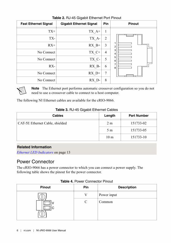
Table 2. RJ-45 Gigabit Ethernet Port Pinout
Fast Ethernet Signal Gigabit Ethernet Signal Pin Pinout
TX+ TX_A+ 1
12345678
TX- TX_A- 2
RX+ RX_B+ 3
No Connect TX_C+ 4
No Connect TX_C- 5
RX- RX_B- 6
No Connect RX_D+ 7
No Connect RX_D- 8
Note The Ethernet port performs automatic crossover configuration so you do notneed to use a crossover cable to connect to a host computer.
The following NI Ethernet cables are available for the cRIO-9066.
Table 3. RJ-45 Gigabit Ethernet Cables
Cables Length Part Number
CAT-5E Ethernet Cable, shielded 2 m 151733-02
5 m 151733-05
10 m 151733-10
Related InformationEthernet LED Indicators on page 13
Power ConnectorThe cRIO-9066 has a power connector to which you can connect a power supply. Thefollowing table shows the pinout for the power connector.
Table 4. Power Connector Pinout
Pinout Pin Description
V
C
V Power input
C Common
6 | ni.com | NI cRIO-9066 User Manual
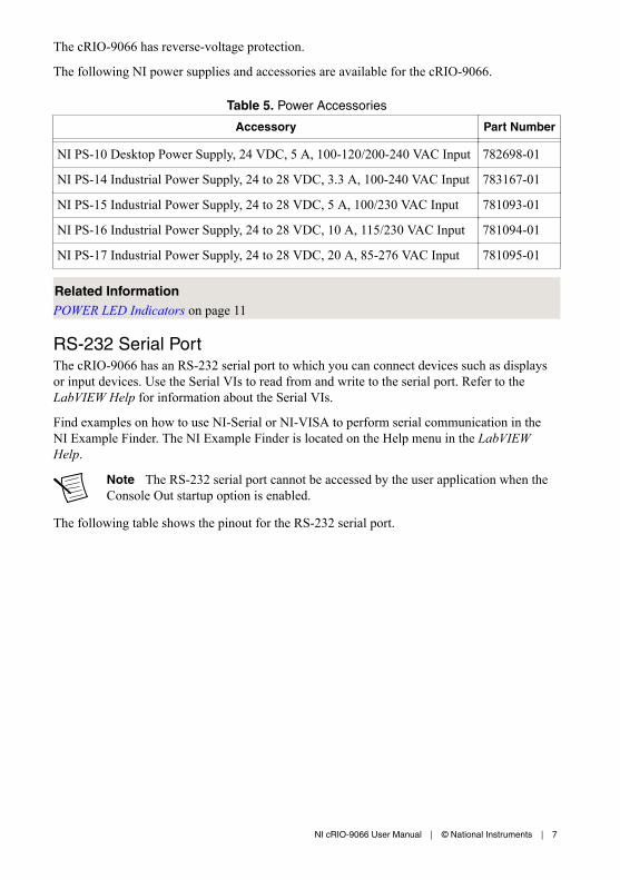
The cRIO-9066 has reverse-voltage protection.
The following NI power supplies and accessories are available for the cRIO-9066.
Table 5. Power Accessories
Accessory Part Number
NI PS-10 Desktop Power Supply, 24 VDC, 5 A, 100-120/200-240 VAC Input 782698-01
NI PS-14 Industrial Power Supply, 24 to 28 VDC, 3.3 A, 100-240 VAC Input 783167-01
NI PS-15 Industrial Power Supply, 24 to 28 VDC, 5 A, 100/230 VAC Input 781093-01
NI PS-16 Industrial Power Supply, 24 to 28 VDC, 10 A, 115/230 VAC Input 781094-01
NI PS-17 Industrial Power Supply, 24 to 28 VDC, 20 A, 85-276 VAC Input 781095-01
Related InformationPOWER LED Indicators on page 11
RS-232 Serial PortThe cRIO-9066 has an RS-232 serial port to which you can connect devices such as displaysor input devices. Use the Serial VIs to read from and write to the serial port. Refer to theLabVIEW Help for information about the Serial VIs.
Find examples on how to use NI-Serial or NI-VISA to perform serial communication in theNI Example Finder. The NI Example Finder is located on the Help menu in the LabVIEWHelp.
Note The RS-232 serial port cannot be accessed by the user application when theConsole Out startup option is enabled.
The following table shows the pinout for the RS-232 serial port.
NI cRIO-9066 User Manual | © National Instruments | 7
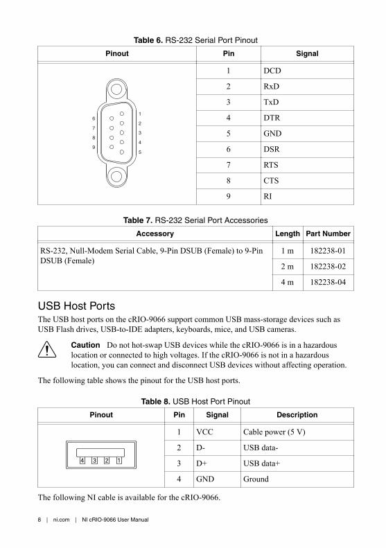
Table 6. RS-232 Serial Port Pinout
Pinout Pin Signal
1
2
3
4
5
6
7
8
9
1 DCD
2 RxD
3 TxD
4 DTR
5 GND
6 DSR
7 RTS
8 CTS
9 RI
Table 7. RS-232 Serial Port Accessories
Accessory Length Part Number
RS-232, Null-Modem Serial Cable, 9-Pin DSUB (Female) to 9-PinDSUB (Female)
1 m 182238-01
2 m 182238-02
4 m 182238-04
USB Host PortsThe USB host ports on the cRIO-9066 support common USB mass-storage devices such asUSB Flash drives, USB-to-IDE adapters, keyboards, mice, and USB cameras.
Caution Do not hot-swap USB devices while the cRIO-9066 is in a hazardouslocation or connected to high voltages. If the cRIO-9066 is not in a hazardouslocation, you can connect and disconnect USB devices without affecting operation.
The following table shows the pinout for the USB host ports.
Table 8. USB Host Port Pinout
Pinout Pin Signal Description
14 23
1 VCC Cable power (5 V)
2 D- USB data-
3 D+ USB data+
4 GND Ground
The following NI cable is available for the cRIO-9066.
8 | ni.com | NI cRIO-9066 User Manual

Table 9. USB Host Port Cable
Cable Length Part Number
USB Extension with Retention, Type A Connectors 0.5 m 152166-0R5
2 m 152166-02
Related InformationFile System on page 14
USB Device PortThe cRIO-9066 USB device port is intended for device configuration, application deployment,debugging, and maintenance. For example, you can use the USB device port to install softwareor driver updates during field maintenance instead of interrupting communication on the RJ-45Ethernet ports.
Caution Do not hot-swap USB devices while the cRIO-9066 is in a hazardouslocation or connected to high voltages. If the cRIO-9066 is not in a hazardouslocation, you can connect and disconnect USB devices without affecting operation.
The following table shows the pinout for the USB device port.
Description Signal Pin Pinout Pin Signal Description
USB data+ D+ 3
14
23
2 D- USB data-
Ground GND 4 1 VCC Cable power (5 V)
The following NI cable is available for the cRIO-9066.
Table 10. USB Device Port Cable
Cable Length Part Number
NI Locking USB Cable 1 m 157788-01
ButtonsThe cRIO-9066 provides the following buttons.
NI cRIO-9066 User Manual | © National Instruments | 9

Figure 2. cRIO-9066 Buttons
1
1. RESET Button
RESET ButtonPress the RESET button to reset the processor in the same manner as cycling power.
Troubleshooting Network ConnectivityYou can use the RESET button to troubleshoot network connectivity.
Complete the following steps to reset the network adapters to default settings.1. Hold the RESET button for 5 seconds, and then release it to boot the controller in safe
mode and enable Console Out.2. Hold the RESET button again for 5 seconds to boot the controller into safe mode, enable
Console Out, and reset network adapters to default settings.
System ResetThe following figure shows the reset behavior of the cRIO-9066.
10 | ni.com | NI cRIO-9066 User Manual

Figure 3. Reset Button Behavior
Press and hold RESET button for ≥ 5 s
Press and hold RESET button for < 5 sRun Mode
Safe ModePress and hold RESET button for < 5 s
Press and hold RESET button for ≥ 5 s
Press and holdRESET button for ≥ 5 s
Press and holdRESET button for < 5 s
• Console Out enabled• Network settings reset• RT Startup App disabled• FPGA Startup App disabled
• Console Out enabled
• RT Startup App disabled
• FPGA Startup App disabled
Safe Mode
LEDsThe cRIO-9066 provides the following LEDs.
Figure 4. cRIO-9066 LEDs
1
5
23
4
1. POWER LED2. STATUS LED3. USER1 LED
4. USER FPGA1 LED5. RJ-45 Ethernet LEDs
POWER LED IndicatorsThe following table lists the POWER LED indicators.
NI cRIO-9066 User Manual | © National Instruments | 11
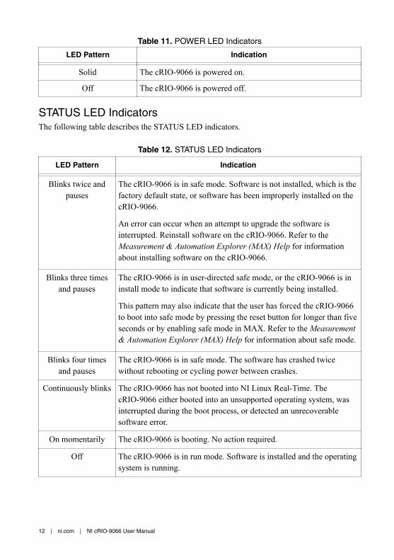
Table 11. POWER LED Indicators
LED Pattern Indication
Solid The cRIO-9066 is powered on.
Off The cRIO-9066 is powered off.
STATUS LED IndicatorsThe following table describes the STATUS LED indicators.
Table 12. STATUS LED Indicators
LED Pattern Indication
Blinks twice andpauses
The cRIO-9066 is in safe mode. Software is not installed, which is thefactory default state, or software has been improperly installed on thecRIO-9066.
An error can occur when an attempt to upgrade the software isinterrupted. Reinstall software on the cRIO-9066. Refer to theMeasurement & Automation Explorer (MAX) Help for informationabout installing software on the cRIO-9066.
Blinks three timesand pauses
The cRIO-9066 is in user-directed safe mode, or the cRIO-9066 is ininstall mode to indicate that software is currently being installed.
This pattern may also indicate that the user has forced the cRIO-9066to boot into safe mode by pressing the reset button for longer than fiveseconds or by enabling safe mode in MAX. Refer to the Measurement& Automation Explorer (MAX) Help for information about safe mode.
Blinks four timesand pauses
The cRIO-9066 is in safe mode. The software has crashed twicewithout rebooting or cycling power between crashes.
Continuously blinks The cRIO-9066 has not booted into NI Linux Real-Time. ThecRIO-9066 either booted into an unsupported operating system, wasinterrupted during the boot process, or detected an unrecoverablesoftware error.
On momentarily The cRIO-9066 is booting. No action required.
Off The cRIO-9066 is in run mode. Software is installed and the operatingsystem is running.
12 | ni.com | NI cRIO-9066 User Manual
User LEDsYou can define the USER1 and USER FPGA1 LEDs to meet the needs of your application.The following table lists the USER1 and USER FPGA1 LED indicators.
Table 13. User LEDs
LED LED Color Description
USER1 Green Use LabVIEW Real-Time to define the USER1 LED with theRT LEDs VI. For more information about the RT LEDs VI, referto the LabVIEW Help.
USERFPGA1
Green Use the LabVIEW FPGA Module and NI-RIO Device Driverssoftware to define the USER FPGA1 LED. Use the USERFPGA1 LED to help debug your application or retrieveapplication status. Refer to the LabVIEW Help for informationabout programming this LED.
Ethernet LED IndicatorsThe following table lists the Ethernet LED indicators.
Table 14. Ethernet LED Indicators
LED LED Color LED Pattern Indication
ACT/LINK — Off LAN link not established
Green Solid LAN link established
Flashing Activity on LAN
10/100/1000 Yellow Solid 1,000 Mbit/s data rate selected
Green Solid 100 Mbit/s data rate selected
— Off 10 Mbit/s data rate selected
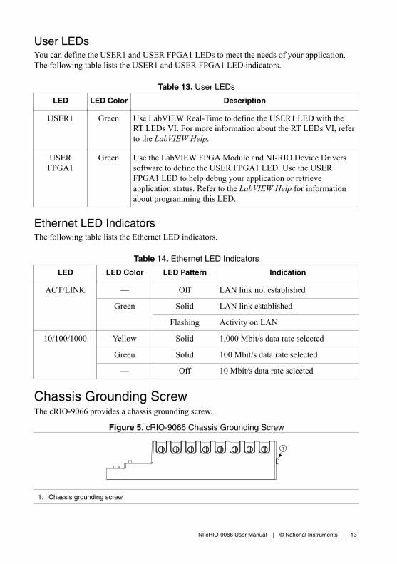
Chassis Grounding ScrewThe cRIO-9066 provides a chassis grounding screw.
Figure 5. cRIO-9066 Chassis Grounding Screw
1
1. Chassis grounding screw
NI cRIO-9066 User Manual | © National Instruments | 13
For EMC compliance, you must connect the cRIO-9066 to earth ground through the chassisground screw. Use wire that is 2.1 mm2 (14 AWG) solid copper wire with a maximum lengthof 1.5 m (5 ft). Attach the wire to the earth ground of the electrode system of the facility.
Caution If you use shielded cabling to connect to a C Series module with a plasticconnector, you must attach the cable shield to the chassis grounding terminal using2.1 mm2 (14 AWG) or larger wire. Attach a ring lug to the wire and attach the wireto the chassis grounding terminal. Solder the other end of the wire to the cableshield. Use shorter wire for better EMC performance.
For more information about ground connections, visit ni.com/info and enter the Info Codeemcground.
Internal Real-Time ClockThe cRIO-9066 contains an internal real-time clock that maintains system time when thecRIO-9066 is powered off. The system clock of the cRIO-9066 is synchronized with theinternal real-time clock at startup. You can set the real-time clock using MAX, or you can setthe clock programmatically using LabVIEW.
Refer to the specifications on ni.com/manuals for the real-time clock accuracy specifications.
BatteryThe cRIO-9066 contains a lithium cell battery that stores the system clock information whenthe cRIO-9066 is powered off. There is only a slight drain on the battery when power isapplied to the cRIO-9066 power connector. The rate at which the battery drains when power isdisconnected depends on the ambient storage temperature. For longer battery life, store thecRIO-9066 at a cooler temperature and apply power to the power connector. Refer to thespecifications on ni.com/manuals for the expected battery lifetime.
The battery is not user-replaceable. If you need to replace the battery, contact NI. Refer to thespecifications on ni.com/manuals for information about battery disposal.
File SystemLabVIEW mounts USB devices to the media/sdx1 directory and creates symboliclinks /u, /v, /w, or /x to the media mount point, starting with /u if it is available. To preventany file corruption to external storage devices, verify that any file IO operations with thespecific drive finish before removing the device. Refer to the LabVIEW Help for moreinformation.
The file system of the cRIO-9066 follows conventions established for UNIX-style operatingsystems. Other LabVIEW Real-Time targets follow Microsoft Windows-style conventions. Inorder to facilitate the porting of applications from those targets, this target supports theWindows-style /C home directory. This path is bound to the UNIX-style directory /home/lvuser.
Various LabVIEW Real-Time system files which would be accessible from C: (or /C) onother LabVIEW Real-Time targets are found in different locations on this target.
UNIX-style file systems support the concept of a symbolic link, which allows access to a fileusing an alternative file path. For example, it is possible to link /C/ni-rt/system, where
14 | ni.com | NI cRIO-9066 User Manual

dynamic libraries are deployed on other LabVIEW Real-Time targets, to /usr/local/lib,where they are stored on the cRIO-9066, if the application requires this.
For more information, visit ni.com/info and enter the Info Code RT_Paths.
Mounting the DeviceTo obtain the maximum allowable ambient temperature of 55 °C, you must mount thecRIO-9066 horizontally on a flat, metallic, vertical surface such as a panel or wall. You canmount the cRIO-9066 directly to the surface or use the NI Panel Mounting Kit. The followingfigure shows the cRIO-9066 mounted horizontally.
Figure 6. cRIO-9066 Horizontal Mounting
1
1. Up
You can also mount the cRIO-9066 in other orientations, on a nonmetallic surface, on a35-mm DIN rail, on a desktop, or in a rack. Mounting the cRIO-9066 in these or otherconfigurations can reduce the maximum allowable ambient temperature and can affect thetypical accuracy of modules in the cRIO-9066. For more information about typical accuracyspecifications for C Series modules and temperature deratings caused by different mountingconfigurations, visit ni.com/info and enter the Info Code criotypical.
Caution Make sure that no C Series modules are in the cRIO-9066 beforemounting it.
Tip Before using any of these mounting methods, record the serial number fromthe back of the cRIO-9066 so that you can identify the cRIO-9066 in MAX. Youwill be unable to read the serial number after you mount the cRIO-9066.
DimensionsThe following figures show the front and side dimensions of the cRIO-9066. For detaileddimensional drawings and 3D models, visit ni.com/dimensions and search for the modulenumber.
NI cRIO-9066 User Manual | © National Instruments | 15

Figure 7. cRIO-9066 Front Dimensions
272.8 mm(10.74 in.)
88.1 mm(3.47 in.)
4.1 mm(0.16 in.)
Figure 8. cRIO-9066 Side Dimensions
44.1 mm(1.74 in.) 29.3 mm
(1.15 in.)
14.1 mm(0.55 in.)
44.1 mm(1.73 in.)
Mounting RequirementsYour installation must meet the following requirements for cooling and cabling clearance.
Allow 25.4 mm (1.00 in.) on the top and the bottom of the cRIO-9066 for air circulation, asshown in the following figure.
Figure 9. cRIO-9066 Cooling Dimensions
25.4 mm (1.00 in.)
25.4 mm (1.00 in.)
16 | ni.com | NI cRIO-9066 User Manual

Allow the appropriate space in front of C Series modules for cabling clearance, as shown inthe following figure. The different connector types on C Series modules require differentcabling clearances. For a complete list of cabling clearances for C Series modules, visit ni.com/info and enter the Info Code crioconn.
Figure 10. cRIO-9066 Cabling Clearance
62.3 mm(2.45 in.)
25.4 mm(1.00 in.)
122
63.5 mm(2.50 in.)
Cabling Clearance 50.8 mm (2.00 in.)
29.1 mm(1.14 in.)
50.8 mm(2.00 in.)
25.4 mm(1.00 in.)
63.5 mm(2.50 in.)
Ambient TemperatureMeasure the ambient temperature at each side of the cRIO-9066, 63.5 mm (2.50 in.) from theside and 25.4 mm (1.00 in.) forward from the rear of the cRIO-9066, as shown in thefollowing figure.
Figure 11. cRIO-9066 Ambient Temperature Location
25.4 mm(1.00 in.)
1
11
63.5 mm(2.50 in.)
25.4 mm(1.00 in.)
63.5 mm(2.50 in.)
63.5 mm(2.50 in.)
63.5 mm(2.50 in.)
1
1. Location for measuring the ambient temperature
Mounting the Device Directly on a Flat SurfaceFor environments with high shock and vibration, NI recommends mounting the cRIO-9066directly on a flat, rigid surface using the mounting holes in the cRIO-9066.
NI cRIO-9066 User Manual | © National Instruments | 17
What to Use
• cRIO-9066• Screwdriver, Phillips #2• M4 or number 8 screw (x2), user-provided, longer than 23.00 mm (0.91 in.) to pass all
the way through the cRIO-9066
What to Do
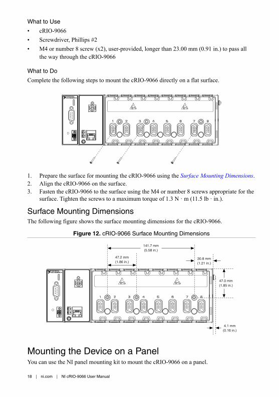
Complete the following steps to mount the cRIO-9066 directly on a flat surface.
1. Prepare the surface for mounting the cRIO-9066 using the Surface Mounting Dimensions.2. Align the cRIO-9066 on the surface.3. Fasten the cRIO-9066 to the surface using the M4 or number 8 screws appropriate for the
surface. Tighten the screws to a maximum torque of 1.3 N · m (11.5 lb · in.).
Surface Mounting DimensionsThe following figure shows the surface mounting dimensions for the cRIO-9066.
Figure 12. cRIO-9066 Surface Mounting Dimensions
47.2 mm(1.86 in.)
141.7 mm(5.58 in.)
30.8 mm(1.21 in.)
47.0 mm(1.85 in.)
4.1 mm(0.16 in.)
Mounting the Device on a PanelYou can use the NI panel mounting kit to mount the cRIO-9066 on a panel.
18 | ni.com | NI cRIO-9066 User Manual

What to Use
• cRIO-9066• Screwdriver, Phillips #2• NI panel mounting kit, 782863-01
– Panel mounting plate– M5 or number 10 screw (x4)
What to Do
Complete the following steps to mount the cRIO-9066 on a panel.
1. Align the cRIO-9066 and the panel mounting plate.2. Fasten the panel mounting plate to the cRIO-9066 using the screwdriver and M5 or
number 10 screws. NI provides these screws with the panel mounting kit. Tighten thescrews to a maximum torque of 1.3 N · m (11.5 lb · in.).
Note You must use the screws provided with the NI panel mounting kitbecause they are the correct depth and thread for the panel mounting plate.
3. Fasten the panel mounting plate to the surface using the screwdriver and screws that areappropriate for the surface. The maximum screw size is M5 or number 10.
Panel Mounting DimensionsThe following figure shows the panel mounting dimensions for the cRIO-9066.
NI cRIO-9066 User Manual | © National Instruments | 19
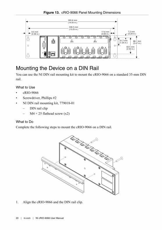
Figure 13. cRIO-9066 Panel Mounting Dimensions
355.6 mm(14.00 in.)
336.5 mm(13.25 in.)
9.5 mm(0.38 in.)
17.6 mm(0.69 in.)
88.1 mm(3.47 in.)
31.7 mm(1.25 in.)
63.5 mm(2.50 in.)
7.2 mm(0.29 in.)
Mounting the Device on a DIN RailYou can use the NI DIN rail mounting kit to mount the cRIO-9066 on a standard 35-mm DINrail.
What to Use
• cRIO-9066• Screwdriver, Phillips #2• NI DIN rail mounting kit, 779018-01
– DIN rail clip– M4 × 25 flathead screw (x2)
What to Do
Complete the following steps to mount the cRIO-9066 on a DIN rail.
1. Align the cRIO-9066 and the DIN rail clip.
20 | ni.com | NI cRIO-9066 User Manual

2. Fasten the DIN rail kit to the cRIO-9066 using the screwdriver and M4 × 25 flatheadscrews. NI provides these screws with the DIN rail mounting kit. Tighten the screws to amaximum torque of 1.3 N · m (11.5 lb · in.).
Note You must use the screws provided with the NI DIN rail mounting kitbecause they are the correct depth and thread for the DIN rail clip.
Clipping the Device on a DIN RailComplete the following steps to clip the cRIO-9066 on a DIN rail.
1
2
1. Insert one edge of the DIN rail into the deeper opening of the DIN rail clip.2. Press down firmly to compress the spring until the clip locks in place on the DIN rail.
Caution Ensure that no C Series modules are in the cRIO-9066 before removing itfrom the DIN rail.
Mounting the Device on a RackYou can use the following rack mount kits to mount the cRIO-9066 and other DIN rail-mountable equipment on a standard 482.6 mm (19 in.) rack.• NI Sliding Rack-Mounting Kit, 779102-01• NI Rack-Mounting Kit, 781989-01
Note You must use the NI DIN rail mounting kit, 779018-01, in addition to a rack-mounting kit.
Mounting the Device on a DesktopYou can use the NI desktop mounting kit to mount the cRIO-9066 on a desktop.
What to Use
• cRIO-9066• Screwdriver, Phillips #1• Screwdriver, Phillips #2• NI desktop mounting kit, 779473-01
NI cRIO-9066 User Manual | © National Instruments | 21

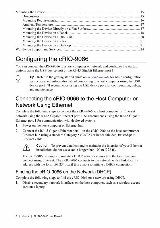
Figure 14. Components of the NI Desktop Mount Kit
2 31 4
1. Desktop mounting brackets (x2)2. Adapter bracket
3. M3x14 screws (x2)4. M3x20 screws (x2)
What to Do
Complete the following steps to mount the cRIO-9066 on a desktop.
22 | ni.com | NI cRIO-9066 User Manual

2
1
3
4
4
3
1. Use a #1 Phillips screwdriver to remove the two screws from the back of the chassis onthe front-panel side.
2. Use the screwdriver and the two M3x20 screws to attach the adapter bracket to thechassis.
3. Align one of the end brackets with the mounting hole at one of the ends of the chassis.4. Use a #2 Phillips screwdriver to tighten the captive screw on the end bracket.5. Repeat steps 2 and 3 to attach the other end bracket to the other end of the chassis.
Desktop Mounting DimensionsThe following figures show the desktop mounting dimensions for the cRIO-9066.
NI cRIO-9066 User Manual | © National Instruments | 23

Figure 15. cRIO-9066 Desktop Mounting Front Dimensions
17.2 mm(0.68 in.)
39.1 mm(1.54 in.)
22.9 mm(1.14 in.)
Figure 16. cRIO-9066 Desktop Mounting Side Dimensions
127.0 mm(5.00 in.)
130.0 mm(5.12 in.)
Worldwide Support and ServicesThe NI website is your complete resource for technical support. At ni.com/support, you haveaccess to everything from troubleshooting and application development self-help resources toemail and phone assistance from NI Application Engineers.
Visit ni.com/services for NI Factory Installation Services, repairs, extended warranty, andother services.
Visit ni.com/register to register your NI product. Product registration facilitates technicalsupport and ensures that you receive important information updates from NI.
A Declaration of Conformity (DoC) is our claim of compliance with the Council of theEuropean Communities using the manufacturer’s declaration of conformity. This systemaffords the user protection for electromagnetic compatibility (EMC) and product safety. Youcan obtain the DoC for your product by visiting ni.com/certification. If your product supportscalibration, you can obtain the calibration certificate for your product at ni.com/calibration.
24 | ni.com | NI cRIO-9066 User Manual

NI corporate headquarters is located at 11500 North Mopac Expressway, Austin, Texas,78759-3504. NI also has offices located around the world. For telephone support in the UnitedStates, create your service request at ni.com/support or dial 1 866 ASK MYNI (275 6964). Fortelephone support outside the United States, visit the Worldwide Offices section of ni.com/niglobal to access the branch office websites, which provide up-to-date contact information,support phone numbers, email addresses, and current events.
NI cRIO-9066 User Manual | © National Instruments | 25

Refer to the NI Trademarks and Logo Guidelines at ni.com/trademarks for information on NI trademarks. Other product andcompany names mentioned herein are trademarks or trade names of their respective companies. For patents covering NIproducts/technology, refer to the appropriate location: Help»Patents in your software, the patents.txt file on your media, or theNational Instruments Patent Notice at ni.com/patents. You can find information about end-user license agreements (EULAs)and third-party legal notices in the readme file for your NI product. Refer to the Export Compliance Information at ni.com/legal/export-compliance for the NI global trade compliance policy and how to obtain relevant HTS codes, ECCNs, and otherimport/export data. NI MAKES NO EXPRESS OR IMPLIED WARRANTIES AS TO THE ACCURACY OF THE INFORMATIONCONTAINED HEREIN AND SHALL NOT BE LIABLE FOR ANY ERRORS. U.S. Government Customers: The data contained inthis manual was developed at private expense and is subject to the applicable limited rights and restricted data rights as set forthin FAR 52.227-14, DFAR 252.227-7014, and DFAR 252.227-7015.
© 2016 National Instruments. All rights reserved.
376341B-01 Jun16