NHD Stream Order Possibilities Timothy R. Bondelid Research Triangle Institute Research Triangle...
42
NHD Stream Order Possibilities Timothy R. Bondelid Research Triangle Institute Research Triangle Park, North Carolina 27709 (919)485-7797; fax (919)485-7777 e-mail: [email protected]
-
Upload
edith-jenkins -
Category
Documents
-
view
223 -
download
0
Transcript of NHD Stream Order Possibilities Timothy R. Bondelid Research Triangle Institute Research Triangle...

NHD Stream Order Possibilities
Timothy R. Bondelid
Research Triangle Institute
Research Triangle Park, North Carolina 27709
(919)485-7797; fax (919)485-7777
e-mail: [email protected]

Stream Order
1
1
22
11
31
3

Topics
• The Three Main Characteristics of NHD (and all Reach Files)
• Hydrologic Sequencing and Routing
• Example of NHD Routing, Stream Orders, and Changing Network Density
• “Hydrologic Equity” Example

The Three Main Characteristics
• A Common Numbering Scheme for All Surface Waters in the System– The Reach Number
• A Map Representation of the Surface Water Features
• A Tabular/Database Routing Network

Tabular Routing “Engine” for Modeling
• Invented by Bob Horn, USEPA Retired

Stream Level
3
2
21
12
12
1

Hydrologic Sequence
5
4
63
12
78
9

Stream Order
1
1
22
11
31
3

Stream Number
4
3
31
15
12
1

NHD Example of the Tabular Routing for Stream Orders and Density
• ArcView Presentation

“Hydrologic Equity”
• Define the Network in Terms of Hydrologic Characteristics
• Example in ArcView (RF3) Using Mean Annual Flow Estimates

Summary
• Stream Orders Can be Made With NHD
• Stream Orders are “Sensitive” to the Density Issue
• The NHD is a Very Flexible Network– The Full Richness of the Network Can Be Used
for Varying Levels of Analysis, Display, and Modeling

Thank You!

Water Quality Management and Policy Modeling Tools using the
National-Scale Reach File 3 (RF3) Hydrography Network
Timothy R. Bondelid, Suzanne J. Unger, Randall C. Dodd, and Dario J. Dal Santo,
Research Triangle Institute
Research Triangle Park, North Carolina 27709
(919)485-7797; fax (919)485-7777
e-mail: [email protected]; [email protected]; [email protected]; [email protected]

The National Water Pollution Control Assessment Model (NWPCAM)
• This Work Has Been Funded by The U.S. Environmental Protection Agency
• Acknowledgements:– Dr. Mahesh Podar, Dr. John Powers, and Ms.
Virginia Kibler in the U.S. EPA Office of Water– Dr. Charles Griffiths in the U.S. EPA National
Center for Environmental Economics
• Significant Others:– C. Robert Horn, Mary Jo Kealy, George Van
Houtven, and Tayler Bingham

Agenda
• Overview of Approach
• Major Challenges
• Assessment Framework
• Hydrologic Components
• Example of Results
• Conclusions
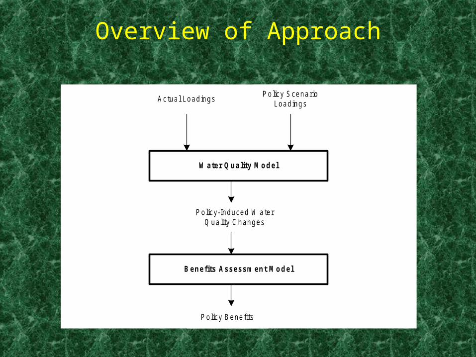
Overview of Approach
Actual LoadingsPolicy Scenario
Loadings
W ater Quality M odel
Policy-Induced W aterQ uality C hanges
Benefits Assessment M odel
Policy Benefits

Major Challenges
• Need to be Able to Evaluate Large-Scale Changes Due to Pollution Control Policies
But: Water Quality is Generally a “Local” Issue
• Need to Link to Economic Benefits
• Addressing These Two Challenges Makes the System Unique

The 18 Hydrologic Basins

The 2100 HUC’s

Subset of Reach File Version 1

Hydrologic Region 7 with RF1

Assessment Framework
H ow m uch water?
H ow deep, w ide fast, e tc .?
Poin t sources (PS)N onpoin t sources (N PS)
M oving from reach to reach
W hat happens to the constituentsin the water?
W ater qua lity (W Q )
Hydrology
Transport
Kinetics
Effects
Loadings
Hydrodynamics

Reach Files and Modeling
• Any Reach File Contains Three Elements:– A Standard, Unique Identifier for Each Surface
Water Feature in the System– A Digital Map Representation of the Features– A Tabular Routing/Navigation “Engine” that is
Powerful and Fast
The Reach Files Have Been Used for Modeling Since 1982

RF1 In Upper Potomac
S
N
EW
Reach File 1 (RF1)
HUC 02070003HUC 02070004HUC 02070008

RF3 in Upper Potomac
HUC 02070003HUC 02070004HUC 02070008
Reach File 3(RF3)
S
N
EW

RF3Lite in Upper Potomac
Reach File 3 Lite(RF3 Lite)
S
N
EW
HUC 02070003HUC 02070004HUC 02070008
Reach File 3(RF3)

Hydrology: How Much Water?
• Estimate Average Unit Runoff by HUC
• Estimate Drainage Area for Each RF3 Reach
• Route and Accumulate Drainage Areas and Flows Down RF3

Average Annual Runoff
• Use “Hydrologic Centroids” of HUC’s
• Apply Distance-weighted Average of Annual Unit Runoff for USGS NCD Gages
• Testing:– HUC-level Unit Runoff– Drainage Areas– Flows

USGS Isopleths of Unit Runoff

Calculated Unit Runoff By HUC

Drainage Areas: Connecting Land Cover Database to RF3 Reaches

USGS Drainage Areas Vs. RF3 Drainage Areas

USGS Flows Vs. RF3 Flows
USGS Flow vs RF3 Flow
0
200
400
600
800
1000
1200
1400
1600
1800
2000
0 200 400 600 800 1000 1200 1400 1600 1800
USGS Flow
RF
3 F
low

How Deep, Wide, Fast?
H ow m uch water?
H ow deep, w ide fast, e tc .?
Point sources (PS)N onpoint sources (N PS)
M oving from reach to reach
W hat happens to the constituentsin the water?
W ater quality (W Q )
Hydrology
Transport
Kinetics
Effects
Loadings
Hydrodynamics

Basic Hydraulics
• Assume Rectangular Channel• Manning’s “n” is a Function of “Sinuosity” of
the Reach:– Sinuosity is the Reach Length/CFD
– CFD = “Crow Fly Distance”
– Reach “n” Increases as Sinousity Increases
• Slopes Derived From RF1/DEM-based Data• Channel Widths From RF3 Geometry or
Keup-derived Function for single-line streams

RF3Lite: Open Water Widths and Sinuosities
Reach File 3 Lite(RF3 Lite)
Open Water
HUC 02070003HUC 02070004HUC 02070008
S
N
EW

Channel Widths and Depths
• Single-Line Stream Widths (Keup):– W = 5.27 * Q 0.459
• Double-Wide Channel Widths from RF3 Geometry
• Depth: Manning’s Formula Assuming a Rectangular Channel– Y0 = 0.79 * (Q * n /(W * (S0)0.5)0.6

The Whole Process
H ow m uch water?
H ow deep, w ide fast, e tc .?
Point sources (PS)N onpoint sources (N PS)
M oving from reach to reach
W hat happens to the constituentsin the water?
W ater quality (W Q )
Hydrology
Transport
Kinetics
Effects
Loadings
Hydrodynamics

Example: Two Scenarios on a Stretch of River
Dissolved Oxygen Concentration
0
1
2
3
4
5
6
7
8
9
184018601880190019201940196019802000
P Mile
Co
nce
ntr
ati
on
(m
g/L
)
Baseline
Scenario

Conclusion: NWPCAM is an Evolving System with Every Component
Undergoing Enhancements
Actual LoadingsPolicy Scenario
Loadings
W ater Quality M odel
Policy-Induced W aterQ uality C hanges
Benefits Assessment M odel
Policy Benefits

Thank You!