NFX250 Network Services Platform Hardware Guide
184
NFX250 Network Services Platform Hardware Guide Modified: 2016-12-13 Copyright © 2016, Juniper Networks, Inc.
Transcript of NFX250 Network Services Platform Hardware Guide

NFX250 Network Services Platform HardwareGuide
Modified: 2016-12-13
Copyright © 2016, Juniper Networks, Inc.

Juniper Networks, Inc.1133 InnovationWaySunnyvale, California 94089USA408-745-2000www.juniper.net
Copyright © 2016, Juniper Networks, Inc. All rights reserved.
Juniper Networks, Junos, Steel-Belted Radius, NetScreen, and ScreenOS are registered trademarks of Juniper Networks, Inc. in the UnitedStates and other countries. The Juniper Networks Logo, the Junos logo, and JunosE are trademarks of Juniper Networks, Inc. All othertrademarks, service marks, registered trademarks, or registered service marks are the property of their respective owners.
Juniper Networks assumes no responsibility for any inaccuracies in this document. Juniper Networks reserves the right to change, modify,transfer, or otherwise revise this publication without notice.
NFX250 Network Services Platform Hardware GuideCopyright © 2016, Juniper Networks, Inc.All rights reserved.
The information in this document is current as of the date on the title page.
YEAR 2000 NOTICE
Juniper Networks hardware and software products are Year 2000 compliant. Junos OS has no known time-related limitations through theyear 2038. However, the NTP application is known to have some difficulty in the year 2036.
ENDUSER LICENSE AGREEMENT
The Juniper Networks product that is the subject of this technical documentation consists of (or is intended for use with) Juniper Networkssoftware. Use of such software is subject to the terms and conditions of the End User License Agreement (“EULA”) posted athttp://www.juniper.net/support/eula.html. By downloading, installing or using such software, you agree to the terms and conditions ofthat EULA.
Copyright © 2016, Juniper Networks, Inc.ii

Table of Contents
About the Documentation . . . . . . . . . . . . . . . . . . . . . . . . . . . . . . . . . . . . . . . . . . . . xi
Documentation and Release Notes . . . . . . . . . . . . . . . . . . . . . . . . . . . . . . . . . . xi
Documentation Conventions . . . . . . . . . . . . . . . . . . . . . . . . . . . . . . . . . . . . . . . xi
Documentation Feedback . . . . . . . . . . . . . . . . . . . . . . . . . . . . . . . . . . . . . . . . xiii
Requesting Technical Support . . . . . . . . . . . . . . . . . . . . . . . . . . . . . . . . . . . . . xiv
Self-Help Online Tools and Resources . . . . . . . . . . . . . . . . . . . . . . . . . . . xiv
Opening a Case with JTAC . . . . . . . . . . . . . . . . . . . . . . . . . . . . . . . . . . . . . xiv
Part 1 Overview
Chapter 1 System Overview . . . . . . . . . . . . . . . . . . . . . . . . . . . . . . . . . . . . . . . . . . . . . . . . . . . 3
NFX250 Device Hardware Overview . . . . . . . . . . . . . . . . . . . . . . . . . . . . . . . . . . . . . 3
NFX250 Hardware . . . . . . . . . . . . . . . . . . . . . . . . . . . . . . . . . . . . . . . . . . . . . . . 3
System Software . . . . . . . . . . . . . . . . . . . . . . . . . . . . . . . . . . . . . . . . . . . . . . . . 4
NFX250 Device Models . . . . . . . . . . . . . . . . . . . . . . . . . . . . . . . . . . . . . . . . . . . . . . . 4
Chapter 2 Chassis Components and Descriptions . . . . . . . . . . . . . . . . . . . . . . . . . . . . . . . . 7
Chassis Physical Specifications for an NFX250 Device . . . . . . . . . . . . . . . . . . . . . . 7
Front Panel of an NFX250 Device . . . . . . . . . . . . . . . . . . . . . . . . . . . . . . . . . . . . . . . 7
Rear Panel of an NFX250 Device . . . . . . . . . . . . . . . . . . . . . . . . . . . . . . . . . . . . . . . . 8
Chassis Status LEDs on NFX250 Devices . . . . . . . . . . . . . . . . . . . . . . . . . . . . . . . . . 9
Network Port and Uplink Port LEDs on NFX250 Devices . . . . . . . . . . . . . . . . . . . . 10
Management Port LEDs on NFX250 Devices . . . . . . . . . . . . . . . . . . . . . . . . . . . . . . 12
Chapter 3 Cooling System and Airflow . . . . . . . . . . . . . . . . . . . . . . . . . . . . . . . . . . . . . . . . . 15
Cooling System and Airflow in an NFX250 Device . . . . . . . . . . . . . . . . . . . . . . . . . 15
Chapter 4 Power Supplies . . . . . . . . . . . . . . . . . . . . . . . . . . . . . . . . . . . . . . . . . . . . . . . . . . . . 17
Power Supply in NFX250 Devices . . . . . . . . . . . . . . . . . . . . . . . . . . . . . . . . . . . . . . . 17
Part 2 Site Planning, Preparation, and Specifications
Chapter 5 Preparation Overview . . . . . . . . . . . . . . . . . . . . . . . . . . . . . . . . . . . . . . . . . . . . . . 21
Site Preparation Checklist for NFX250 Devices . . . . . . . . . . . . . . . . . . . . . . . . . . . . 21
Environmental Requirements and Specifications for an NFX250 Device . . . . . . . 23
General Site Guidelines . . . . . . . . . . . . . . . . . . . . . . . . . . . . . . . . . . . . . . . . . . . . . . 24
Site Electrical Wiring Guidelines . . . . . . . . . . . . . . . . . . . . . . . . . . . . . . . . . . . . . . . 24
Requirements for Mounting an NFX250 Device on a Desktop or Other Level
Surface . . . . . . . . . . . . . . . . . . . . . . . . . . . . . . . . . . . . . . . . . . . . . . . . . . . . . . . 25
Requirements for Mounting an NFX250-LS1 Device on a Wall . . . . . . . . . . . . . . . 25
Rack Requirements for NFX250 Devices . . . . . . . . . . . . . . . . . . . . . . . . . . . . . . . . 26
Cabinet Requirements for an NFX250 Device . . . . . . . . . . . . . . . . . . . . . . . . . . . . . 27
iiiCopyright © 2016, Juniper Networks, Inc.

Clearance Requirements for Airflow and HardwareMaintenance for an NFX250
Device . . . . . . . . . . . . . . . . . . . . . . . . . . . . . . . . . . . . . . . . . . . . . . . . . . . . . . . . 28
Chapter 6 Power Specifications and Requirements . . . . . . . . . . . . . . . . . . . . . . . . . . . . . 31
AC Power Supply Specifications for an NFX250 Device . . . . . . . . . . . . . . . . . . . . . 31
AC Power Cord Specifications for an NFX250 Device . . . . . . . . . . . . . . . . . . . . . . . 31
Chapter 7 Port and Pinout Specifications . . . . . . . . . . . . . . . . . . . . . . . . . . . . . . . . . . . . . . 35
Mini-USB Type-B Console Port Specifications for an NFX250 Device . . . . . . . . . . 35
Console Port Connector Pinouts for NFX250 Devices . . . . . . . . . . . . . . . . . . . . . . 36
USB Port Specifications for an NFX250 Device . . . . . . . . . . . . . . . . . . . . . . . . . . . 37
Management Port Connector Pinout Information for an NFX250 Device . . . . . . . 37
Network Port Connector Pinout Information for an NFX250 Device . . . . . . . . . . . 38
RJ-45 to DB-9 Serial Port Adapter Pinout Information for an NFX250 Device . . . 39
Chapter 8 Transceiver and Cable Specifications . . . . . . . . . . . . . . . . . . . . . . . . . . . . . . . . 41
Pluggable Transceivers Supported on NFX250 Devices . . . . . . . . . . . . . . . . . . . . . 41
SFP+ Direct Attach Cables for NFX250 Devices . . . . . . . . . . . . . . . . . . . . . . . . . . 66
Cable Specifications . . . . . . . . . . . . . . . . . . . . . . . . . . . . . . . . . . . . . . . . . . . . . 67
Standards Supported by These Cables . . . . . . . . . . . . . . . . . . . . . . . . . . . . . . 69
CableSpecifications forConsoleandManagementConnections for theNFX250
Devices . . . . . . . . . . . . . . . . . . . . . . . . . . . . . . . . . . . . . . . . . . . . . . . . . . . . . . . 69
UnderstandingNFX250DevicesFiber-OpticCableSignalLoss,Attenuation,and
Dispersion . . . . . . . . . . . . . . . . . . . . . . . . . . . . . . . . . . . . . . . . . . . . . . . . . . . . . 70
Signal Loss in Multimode and Single-Mode Fiber-Optic Cables . . . . . . . . . . 70
Attenuation and Dispersion in Fiber-Optic Cable . . . . . . . . . . . . . . . . . . . . . . . 71
Calculating the Fiber-Optic Cable Power Budget for an NFX250 Device . . . . . . . . 71
Calculating the Fiber-Optic Cable Power Margin for an NFX250 Device . . . . . . . . 72
Part 3 Initial Installation and Configuration
Chapter 9 Unpacking the Network Services Platform . . . . . . . . . . . . . . . . . . . . . . . . . . . . 77
Unpacking an NFX250 Device . . . . . . . . . . . . . . . . . . . . . . . . . . . . . . . . . . . . . . . . . 77
Parts Inventory (Packing List) for an NFX250 Device . . . . . . . . . . . . . . . . . . . . . . . 77
Registering Products—Mandatory for Validating SLAs . . . . . . . . . . . . . . . . . . . . . . 78
Chapter 10 Installing the Network Services Platform . . . . . . . . . . . . . . . . . . . . . . . . . . . . . 81
Installing and Connecting an NFX250 Device . . . . . . . . . . . . . . . . . . . . . . . . . . . . . 81
Mounting an NFX250 Device . . . . . . . . . . . . . . . . . . . . . . . . . . . . . . . . . . . . . . . . . . 82
Mounting an NFX250 Device on a Desk or Other Level Surface . . . . . . . . . . . . . . . 82
Mounting an NFX250-LS1 Device on a Wall . . . . . . . . . . . . . . . . . . . . . . . . . . . . . . 83
Mounting an NFX250 Device on Two Posts in a Rack . . . . . . . . . . . . . . . . . . . . . . 86
Mounting an NFX250 Device on Four Posts in a Rack or Cabinet . . . . . . . . . . . . . 88
Chapter 11 Connecting the Network Services Platform to Power . . . . . . . . . . . . . . . . . . . 91
Connecting Earth Ground to an NFX250 Device . . . . . . . . . . . . . . . . . . . . . . . . . . . 91
Parts and Tools Required for Connecting an NFX250 Device to Earth
Ground . . . . . . . . . . . . . . . . . . . . . . . . . . . . . . . . . . . . . . . . . . . . . . . . . . . . 91
Connecting Earth Ground to an NFX250 Device . . . . . . . . . . . . . . . . . . . . . . . 92
Connecting AC Power to an NFX250 Device . . . . . . . . . . . . . . . . . . . . . . . . . . . . . . 92
Copyright © 2016, Juniper Networks, Inc.iv
NFX250 Network Services Platform Hardware Guide

Chapter 12 Connecting the Network Services Platform to the Network . . . . . . . . . . . . . 95
Connecting an NFX250 Device to a Network for Out-of-Band Management . . . . 95
Connecting an NFX250 Device to a Management Console . . . . . . . . . . . . . . . . . . 96
ConnectinganNFX250Device toaManagementConsoleUsingMini-USBType-B
Console Port . . . . . . . . . . . . . . . . . . . . . . . . . . . . . . . . . . . . . . . . . . . . . . . . . . . 97
Chapter 13 Initially Configuring the Network Services Platform . . . . . . . . . . . . . . . . . . . 99
Configuring an NFX250 Device . . . . . . . . . . . . . . . . . . . . . . . . . . . . . . . . . . . . . . . . 99
Part 4 Installing, Maintaining, and Replacing Components
Chapter 14 Removing the Network Services Platform . . . . . . . . . . . . . . . . . . . . . . . . . . . 105
Powering Off an NFX250 Device . . . . . . . . . . . . . . . . . . . . . . . . . . . . . . . . . . . . . . 105
Removing an NFX250 Device from a Rack or Cabinet . . . . . . . . . . . . . . . . . . . . . 106
Chapter 15 Replacing Transceiver . . . . . . . . . . . . . . . . . . . . . . . . . . . . . . . . . . . . . . . . . . . . 109
Installing a Transceiver in an NFX250 Device . . . . . . . . . . . . . . . . . . . . . . . . . . . . 109
Removing a Transceiver from an NFX250 Device . . . . . . . . . . . . . . . . . . . . . . . . . 110
Chapter 16 Maintaining and Replacing Fiber-Optic Cable . . . . . . . . . . . . . . . . . . . . . . . . 113
Connecting a Fiber-Optic Cable to an NFX250 Device . . . . . . . . . . . . . . . . . . . . . 113
Disconnecting a Fiber-Optic Cable from an NFX250 Device . . . . . . . . . . . . . . . . . 114
Maintaining Fiber-Optic Cables in an NFX250 Device . . . . . . . . . . . . . . . . . . . . . . 115
Chapter 17 Contacting Customer Support and Returning the Chassis orComponents . . . . . . . . . . . . . . . . . . . . . . . . . . . . . . . . . . . . . . . . . . . . . . . . . . . . . 117
Returning a NFX250 Device or Component for Repair or Replacement . . . . . . . . 117
Locating the Serial Number on an NFX250 Device . . . . . . . . . . . . . . . . . . . . . . . . 118
Listing the Device and Components Details with the CLI . . . . . . . . . . . . . . . . 118
Locating the Chassis Serial Number ID Label on an NFX250 Device . . . . . . . 119
Packing a NFX250 Device or Component for Shipping . . . . . . . . . . . . . . . . . . . . . 119
Packing a NFX250 Device for Shipping . . . . . . . . . . . . . . . . . . . . . . . . . . . . . . 119
Packing NFX250 Device Components for Shipping . . . . . . . . . . . . . . . . . . . . 120
Contacting Customer Support toObtain a ReturnMaterials Authorization for an
NFX250 Device . . . . . . . . . . . . . . . . . . . . . . . . . . . . . . . . . . . . . . . . . . . . . . . . 120
Part 5 Troubleshooting
Chapter 18 AlarmMessages . . . . . . . . . . . . . . . . . . . . . . . . . . . . . . . . . . . . . . . . . . . . . . . . . . 125
Understanding Alarm Types and Severity Levels on NFX250 Devices . . . . . . . . . 125
Part 6 Safety and Compliance Information
Chapter 19 General Safety Guidelines and Warnings . . . . . . . . . . . . . . . . . . . . . . . . . . . . 129
General Safety Guidelines and Warnings . . . . . . . . . . . . . . . . . . . . . . . . . . . . . . . 129
Definitions of Safety Warning Levels . . . . . . . . . . . . . . . . . . . . . . . . . . . . . . . . . . . 130
Qualified Personnel Warning . . . . . . . . . . . . . . . . . . . . . . . . . . . . . . . . . . . . . . . . . 132
Warning Statement for Norway and Sweden . . . . . . . . . . . . . . . . . . . . . . . . . . . . 133
Chapter 20 Fire Safety Requirements . . . . . . . . . . . . . . . . . . . . . . . . . . . . . . . . . . . . . . . . . . 135
Fire Safety Requirements . . . . . . . . . . . . . . . . . . . . . . . . . . . . . . . . . . . . . . . . . . . . 135
vCopyright © 2016, Juniper Networks, Inc.
Table of Contents

Chapter 21 Installation Safety Guidelines and Warnings . . . . . . . . . . . . . . . . . . . . . . . . . 137
Installation Instructions Warning . . . . . . . . . . . . . . . . . . . . . . . . . . . . . . . . . . . . . . 137
Chassis Lifting Guidelines for NFX250 Devices . . . . . . . . . . . . . . . . . . . . . . . . . . . 138
Restricted Access Warning . . . . . . . . . . . . . . . . . . . . . . . . . . . . . . . . . . . . . . . . . . . 138
Ramp Warning . . . . . . . . . . . . . . . . . . . . . . . . . . . . . . . . . . . . . . . . . . . . . . . . . . . . 140
Rack-Mounting and Cabinet-Mounting Warnings . . . . . . . . . . . . . . . . . . . . . . . . 140
Chapter 22 Radiation and Laser Safety Guidelines and Warnings . . . . . . . . . . . . . . . . . 145
Laser and LED Safety Guidelines and Warnings for the NFX250 Devices . . . . . . 145
General Laser Safety Guidelines . . . . . . . . . . . . . . . . . . . . . . . . . . . . . . . . . . . 145
Class 1M Laser Product Warning . . . . . . . . . . . . . . . . . . . . . . . . . . . . . . . . . . . 146
Class 1M Laser Radiation Warning . . . . . . . . . . . . . . . . . . . . . . . . . . . . . . . . . 146
Class 1 Laser Product Warning . . . . . . . . . . . . . . . . . . . . . . . . . . . . . . . . . . . . 146
Class 1 LED Product Warning . . . . . . . . . . . . . . . . . . . . . . . . . . . . . . . . . . . . . . 147
Laser Beam Warning . . . . . . . . . . . . . . . . . . . . . . . . . . . . . . . . . . . . . . . . . . . . 147
Unterminated Fiber-Optic Cable Warning . . . . . . . . . . . . . . . . . . . . . . . . . . . 148
Radiation from Open Port Apertures Warning . . . . . . . . . . . . . . . . . . . . . . . . . . . 149
Chapter 23 Maintenance and Operational Safety Warnings . . . . . . . . . . . . . . . . . . . . . . . 151
Maintenance and Operational Safety Guidelines and Warnings . . . . . . . . . . . . . . 151
Battery Handling Warning . . . . . . . . . . . . . . . . . . . . . . . . . . . . . . . . . . . . . . . . 151
Jewelry Removal Warning . . . . . . . . . . . . . . . . . . . . . . . . . . . . . . . . . . . . . . . . 152
Lightning Activity Warning . . . . . . . . . . . . . . . . . . . . . . . . . . . . . . . . . . . . . . . . 153
Operating Temperature Warning . . . . . . . . . . . . . . . . . . . . . . . . . . . . . . . . . . 154
Product Disposal Warning . . . . . . . . . . . . . . . . . . . . . . . . . . . . . . . . . . . . . . . . 155
Chapter 24 Electrical Safety Guidelines and Warnings . . . . . . . . . . . . . . . . . . . . . . . . . . . 157
General Electrical Safety Guidelines andWarnings . . . . . . . . . . . . . . . . . . . . . . . . 157
Action to Take After an Electrical Accident . . . . . . . . . . . . . . . . . . . . . . . . . . . . . . 158
Prevention of Electrostatic Discharge Damage . . . . . . . . . . . . . . . . . . . . . . . . . . . 159
AC Power Electrical Safety Guidelines . . . . . . . . . . . . . . . . . . . . . . . . . . . . . . . . . 160
AC Power Disconnection Warning . . . . . . . . . . . . . . . . . . . . . . . . . . . . . . . . . . . . . 161
TN Power Warning . . . . . . . . . . . . . . . . . . . . . . . . . . . . . . . . . . . . . . . . . . . . . . . . . 162
Chapter 25 Agency Approvals and Compliance Statements . . . . . . . . . . . . . . . . . . . . . . 163
Agency Approvals for NFX250 Devices . . . . . . . . . . . . . . . . . . . . . . . . . . . . . . . . . 163
Compliance Statements for EMC Requirements for NFX250 Devices . . . . . . . . . 164
Canada . . . . . . . . . . . . . . . . . . . . . . . . . . . . . . . . . . . . . . . . . . . . . . . . . . . . . . 164
European Community . . . . . . . . . . . . . . . . . . . . . . . . . . . . . . . . . . . . . . . . . . . 165
Israel . . . . . . . . . . . . . . . . . . . . . . . . . . . . . . . . . . . . . . . . . . . . . . . . . . . . . . . . . 165
Japan . . . . . . . . . . . . . . . . . . . . . . . . . . . . . . . . . . . . . . . . . . . . . . . . . . . . . . . . 165
Korea . . . . . . . . . . . . . . . . . . . . . . . . . . . . . . . . . . . . . . . . . . . . . . . . . . . . . . . . 166
United States . . . . . . . . . . . . . . . . . . . . . . . . . . . . . . . . . . . . . . . . . . . . . . . . . . 166
FCC Part 15 Statement . . . . . . . . . . . . . . . . . . . . . . . . . . . . . . . . . . . . . . . . . . 166
Nonregulatory Environmental Standards . . . . . . . . . . . . . . . . . . . . . . . . . . . . 167
Copyright © 2016, Juniper Networks, Inc.vi
NFX250 Network Services Platform Hardware Guide

List of Figures
Part 1 Overview
Chapter 1 System Overview . . . . . . . . . . . . . . . . . . . . . . . . . . . . . . . . . . . . . . . . . . . . . . . . . . . 3
Figure 1: NFX250 Port Panel . . . . . . . . . . . . . . . . . . . . . . . . . . . . . . . . . . . . . . . . . . . . 3
Chapter 2 Chassis Components and Descriptions . . . . . . . . . . . . . . . . . . . . . . . . . . . . . . . . 7
Figure 2: NFX250 Front Panel Components . . . . . . . . . . . . . . . . . . . . . . . . . . . . . . . 8
Figure 3: NFX250 Device Switch Rear Panel . . . . . . . . . . . . . . . . . . . . . . . . . . . . . . . 9
Figure 4: Chassis Status LEDs in an NFX250 Device . . . . . . . . . . . . . . . . . . . . . . . . . 9
Figure 5: LEDs on the Network Port . . . . . . . . . . . . . . . . . . . . . . . . . . . . . . . . . . . . . . 11
Figure 6: Port Status Mode LEDs of an NFX250 Device . . . . . . . . . . . . . . . . . . . . . . 11
Figure 7: LEDs on the Management Port of an NFX250 . . . . . . . . . . . . . . . . . . . . . 12
Chapter 3 Cooling System and Airflow . . . . . . . . . . . . . . . . . . . . . . . . . . . . . . . . . . . . . . . . . 15
Figure 8: Front-to-Back Airflow Through the NFX250 Chassis . . . . . . . . . . . . . . . . 15
Part 2 Site Planning, Preparation, and Specifications
Chapter 5 Preparation Overview . . . . . . . . . . . . . . . . . . . . . . . . . . . . . . . . . . . . . . . . . . . . . . 21
Figure 9: Clearance Requirements for Airflow and Hardware Maintenance for
an NFX250 Device . . . . . . . . . . . . . . . . . . . . . . . . . . . . . . . . . . . . . . . . . . . . . . 29
Chapter 6 Power Specifications and Requirements . . . . . . . . . . . . . . . . . . . . . . . . . . . . . 31
Figure 10: AC Plug Types . . . . . . . . . . . . . . . . . . . . . . . . . . . . . . . . . . . . . . . . . . . . . 33
Part 3 Initial Installation and Configuration
Chapter 10 Installing the Network Services Platform . . . . . . . . . . . . . . . . . . . . . . . . . . . . . 81
Figure 11: Attaching Rubber Feet to the NFX250 Device . . . . . . . . . . . . . . . . . . . . . 83
Figure 12: Attaching Wall-Mount Brackets to the NFX250 Device Chassis . . . . . . 84
Figure 13: Measurements for Installing Mounting Screws for NFX250 Device on
a Wall . . . . . . . . . . . . . . . . . . . . . . . . . . . . . . . . . . . . . . . . . . . . . . . . . . . . . . . . 85
Figure 14: Mounting the NFX250 Device on aWall . . . . . . . . . . . . . . . . . . . . . . . . . 86
Figure 15: Attaching the Mounting Bracket to the Side Panel of the Device . . . . . 87
Figure 16: Mounting the Device on Two Posts in a Rack . . . . . . . . . . . . . . . . . . . . . 88
Figure 17: Attaching the Front-Mounting Bracket to the Device Chassis . . . . . . . . 90
Figure 18: Mounting the Device on the Front Posts in a Rack . . . . . . . . . . . . . . . . . 90
Chapter 11 Connecting the Network Services Platform to Power . . . . . . . . . . . . . . . . . . . 91
Figure 19: Connecting a Grounding Cable to an NFX250 Device . . . . . . . . . . . . . . 92
Figure 20: Connecting an AC Power Cord to the AC Power Cord Inlet on NFX250
Device . . . . . . . . . . . . . . . . . . . . . . . . . . . . . . . . . . . . . . . . . . . . . . . . . . . . . . . . 94
Chapter 12 Connecting the Network Services Platform to the Network . . . . . . . . . . . . . 95
viiCopyright © 2016, Juniper Networks, Inc.

Figure 21: Connecting an NFX250 Device to a Network for Out-of-Band
Management . . . . . . . . . . . . . . . . . . . . . . . . . . . . . . . . . . . . . . . . . . . . . . . . . . 96
Figure 22: Connecting the NFX250 Device to a Management Console Through
a Console Server . . . . . . . . . . . . . . . . . . . . . . . . . . . . . . . . . . . . . . . . . . . . . . . . 97
Figure 23: Connecting the NFX250 Device Directly to a Management Console . . 97
Chapter 13 Initially Configuring the Network Services Platform . . . . . . . . . . . . . . . . . . . 99
Figure 24: NFX250 Front Panel Components . . . . . . . . . . . . . . . . . . . . . . . . . . . . . 101
Part 4 Installing, Maintaining, and Replacing Components
Chapter 15 Replacing Transceiver . . . . . . . . . . . . . . . . . . . . . . . . . . . . . . . . . . . . . . . . . . . . 109
Figure 25: Installing a Transceiver in an NFX250 Device . . . . . . . . . . . . . . . . . . . . 110
Figure 26: Removing a Transceiver from an NFX250 Device . . . . . . . . . . . . . . . . . 112
Chapter 16 Maintaining and Replacing Fiber-Optic Cable . . . . . . . . . . . . . . . . . . . . . . . . 113
Figure 27: Inserting a Fiber-Optic Cable into a Transceiver . . . . . . . . . . . . . . . . . . 114
Chapter 17 Contacting Customer Support and Returning the Chassis orComponents . . . . . . . . . . . . . . . . . . . . . . . . . . . . . . . . . . . . . . . . . . . . . . . . . . . . . 117
Figure 28: Location of the Serial Number ID Label on an NFX250 Device . . . . . . 119
Part 6 Safety and Compliance Information
Chapter 24 Electrical Safety Guidelines and Warnings . . . . . . . . . . . . . . . . . . . . . . . . . . . 157
Figure 29: Placing a Component into an Antistatic Bag . . . . . . . . . . . . . . . . . . . . 159
Copyright © 2016, Juniper Networks, Inc.viii
NFX250 Network Services Platform Hardware Guide
List of Tables
About the Documentation . . . . . . . . . . . . . . . . . . . . . . . . . . . . . . . . . . . . . . . . . . xi
Table 1: Notice Icons . . . . . . . . . . . . . . . . . . . . . . . . . . . . . . . . . . . . . . . . . . . . . . . . . xii
Table 2: Text and Syntax Conventions . . . . . . . . . . . . . . . . . . . . . . . . . . . . . . . . . . . xii
Part 1 Overview
Chapter 1 System Overview . . . . . . . . . . . . . . . . . . . . . . . . . . . . . . . . . . . . . . . . . . . . . . . . . . . 3
Table 3: NFX250 Device Models . . . . . . . . . . . . . . . . . . . . . . . . . . . . . . . . . . . . . . . . 4
Chapter 2 Chassis Components and Descriptions . . . . . . . . . . . . . . . . . . . . . . . . . . . . . . . . 7
Table 4: Physical Specifications for the NFX250 Device Chassis . . . . . . . . . . . . . . . 7
Table 5: Chassis Status LEDs in an NFX250 Device . . . . . . . . . . . . . . . . . . . . . . . . 10
Table 6: Link/Activity LED on the Network Ports and Uplink Ports in NFX250
Devices . . . . . . . . . . . . . . . . . . . . . . . . . . . . . . . . . . . . . . . . . . . . . . . . . . . . . . . . 11
Table 7: Status LED on the Network Ports and Uplink Ports in NFX250
Devices . . . . . . . . . . . . . . . . . . . . . . . . . . . . . . . . . . . . . . . . . . . . . . . . . . . . . . . . 12
Table 8: Link/Activity LED on the Management Port of an NFX250 Device . . . . . . 13
Table 9: Status LED on the Management Port of an NFX250 Device . . . . . . . . . . . 13
Part 2 Site Planning, Preparation, and Specifications
Chapter 5 Preparation Overview . . . . . . . . . . . . . . . . . . . . . . . . . . . . . . . . . . . . . . . . . . . . . . 21
Table 10: Site Preparation Checklist . . . . . . . . . . . . . . . . . . . . . . . . . . . . . . . . . . . . . 21
Table 11: NFX250 Device Environmental Tolerances . . . . . . . . . . . . . . . . . . . . . . . . 23
Table 12: Site Electrical Wiring Guidelines . . . . . . . . . . . . . . . . . . . . . . . . . . . . . . . . 24
Table 13: Rack Requirements and Specifications for the Device . . . . . . . . . . . . . . 26
Table 14: Cabinet Requirements for the NFX250 Device . . . . . . . . . . . . . . . . . . . . . 27
Chapter 6 Power Specifications and Requirements . . . . . . . . . . . . . . . . . . . . . . . . . . . . . 31
Table 15: AC Power Specifications for an NFX250 Device . . . . . . . . . . . . . . . . . . . . 31
Table 16: AC Power Cord Specifications . . . . . . . . . . . . . . . . . . . . . . . . . . . . . . . . . 32
Chapter 7 Port and Pinout Specifications . . . . . . . . . . . . . . . . . . . . . . . . . . . . . . . . . . . . . . 35
Table 17: Mini-USB Type-B Console Port Pinout Information for NFX250
Devices . . . . . . . . . . . . . . . . . . . . . . . . . . . . . . . . . . . . . . . . . . . . . . . . . . . . . . . 35
Table 18: Console Port Connector Pinouts for the NFX250 Device . . . . . . . . . . . . 36
Table 19: RJ-45 Management Port Connector Pinouts for the NFX250
Devices . . . . . . . . . . . . . . . . . . . . . . . . . . . . . . . . . . . . . . . . . . . . . . . . . . . . . . . 38
Table 20: Network Port Connector Pinout Information for NFX250 Devices . . . . . 38
Table 21: RJ-45 to DB-9 Serial Port Adapter Pinout Information . . . . . . . . . . . . . . 39
Chapter 8 Transceiver and Cable Specifications . . . . . . . . . . . . . . . . . . . . . . . . . . . . . . . . 41
ixCopyright © 2016, Juniper Networks, Inc.

Table 22: Optical Interface Support and Copper Interface Support for Gigabit
Ethernet SFP Transceivers in NFX250 Devices . . . . . . . . . . . . . . . . . . . . . . . . 42
Table 23: Optical Interface Support for Gigabit Ethernet SFP+ Transceivers in
NFX250 Devices . . . . . . . . . . . . . . . . . . . . . . . . . . . . . . . . . . . . . . . . . . . . . . . . 62
Table 24: SFP+ Direct Attach Copper Cable Specifications . . . . . . . . . . . . . . . . . . 68
Table 25: Cable Specifications for Console and Management Connections for
the NFX250 Devices . . . . . . . . . . . . . . . . . . . . . . . . . . . . . . . . . . . . . . . . . . . . . 70
Table 26: Estimated Values for Factors Causing Link Loss . . . . . . . . . . . . . . . . . . . 73
Part 3 Initial Installation and Configuration
Chapter 9 Unpacking the Network Services Platform . . . . . . . . . . . . . . . . . . . . . . . . . . . . 77
Table 27: Packing List for an NFX250 Device . . . . . . . . . . . . . . . . . . . . . . . . . . . . . 78
Chapter 10 Installing the Network Services Platform . . . . . . . . . . . . . . . . . . . . . . . . . . . . . 81
Table 28: NFX250 Device Mounting Methods . . . . . . . . . . . . . . . . . . . . . . . . . . . . . 82
Chapter 11 Connecting the Network Services Platform to Power . . . . . . . . . . . . . . . . . . . 91
Table 29: Parts and Tools Required for Connecting an NFX250 Device to Earth
Ground . . . . . . . . . . . . . . . . . . . . . . . . . . . . . . . . . . . . . . . . . . . . . . . . . . . . . . . . 92
Part 5 Troubleshooting
Chapter 18 AlarmMessages . . . . . . . . . . . . . . . . . . . . . . . . . . . . . . . . . . . . . . . . . . . . . . . . . . 125
Table 30: Alarm Terms and Definitions . . . . . . . . . . . . . . . . . . . . . . . . . . . . . . . . . 125
Copyright © 2016, Juniper Networks, Inc.x
NFX250 Network Services Platform Hardware Guide

About the Documentation
• Documentation and Release Notes on page xi
• Documentation Conventions on page xi
• Documentation Feedback on page xiii
• Requesting Technical Support on page xiv
Documentation and Release Notes
To obtain the most current version of all Juniper Networks®technical documentation,
see the product documentation page on the Juniper Networks website at
http://www.juniper.net/techpubs/.
If the information in the latest release notes differs from the information in the
documentation, follow the product Release Notes.
Juniper Networks Books publishes books by Juniper Networks engineers and subject
matter experts. These books go beyond the technical documentation to explore the
nuances of network architecture, deployment, and administration. The current list can
be viewed at http://www.juniper.net/books.
Documentation Conventions
Table 1 on page xii defines notice icons used in this guide.
xiCopyright © 2016, Juniper Networks, Inc.
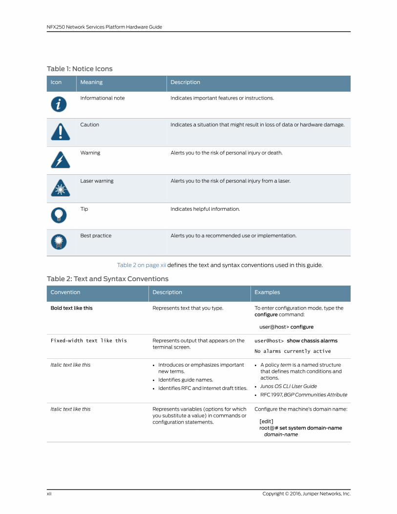
Table 1: Notice Icons
DescriptionMeaningIcon
Indicates important features or instructions.Informational note
Indicates a situation that might result in loss of data or hardware damage.Caution
Alerts you to the risk of personal injury or death.Warning
Alerts you to the risk of personal injury from a laser.Laser warning
Indicates helpful information.Tip
Alerts you to a recommended use or implementation.Best practice
Table 2 on page xii defines the text and syntax conventions used in this guide.
Table 2: Text and Syntax Conventions
ExamplesDescriptionConvention
To enter configuration mode, type theconfigure command:
user@host> configure
Represents text that you type.Bold text like this
user@host> show chassis alarms
No alarms currently active
Represents output that appears on theterminal screen.
Fixed-width text like this
• A policy term is a named structurethat defines match conditions andactions.
• Junos OS CLI User Guide
• RFC 1997,BGPCommunities Attribute
• Introduces or emphasizes importantnew terms.
• Identifies guide names.
• Identifies RFC and Internet draft titles.
Italic text like this
Configure themachine’s domain name:
[edit]root@# set system domain-namedomain-name
Represents variables (options for whichyou substitute a value) in commands orconfiguration statements.
Italic text like this
Copyright © 2016, Juniper Networks, Inc.xii
NFX250 Network Services Platform Hardware Guide

Table 2: Text and Syntax Conventions (continued)
ExamplesDescriptionConvention
• To configure a stub area, include thestub statement at the [edit protocolsospf area area-id] hierarchy level.
• Theconsoleport is labeledCONSOLE.
Represents names of configurationstatements, commands, files, anddirectories; configurationhierarchy levels;or labels on routing platformcomponents.
Text like this
stub <default-metricmetric>;Encloses optional keywords or variables.< > (angle brackets)
broadcast | multicast
(string1 | string2 | string3)
Indicates a choice between themutuallyexclusive keywords or variables on eitherside of the symbol. The set of choices isoften enclosed in parentheses for clarity.
| (pipe symbol)
rsvp { # Required for dynamicMPLS onlyIndicates a comment specified on thesame lineas theconfiguration statementto which it applies.
# (pound sign)
community namemembers [community-ids ]
Encloses a variable for which you cansubstitute one or more values.
[ ] (square brackets)
[edit]routing-options {static {route default {nexthop address;retain;
}}
}
Identifies a level in the configurationhierarchy.
Indention and braces ( { } )
Identifies a leaf statement at aconfiguration hierarchy level.
; (semicolon)
GUI Conventions
• In the Logical Interfaces box, selectAll Interfaces.
• To cancel the configuration, clickCancel.
Representsgraphicaluser interface(GUI)items you click or select.
Bold text like this
In the configuration editor hierarchy,select Protocols>Ospf.
Separates levels in a hierarchy of menuselections.
> (bold right angle bracket)
Documentation Feedback
We encourage you to provide feedback, comments, and suggestions so that we can
improve the documentation. You can provide feedback by using either of the following
methods:
• Online feedback rating system—On any page of the Juniper Networks TechLibrary site
athttp://www.juniper.net/techpubs/index.html, simply click the stars to rate thecontent,
and use the pop-up form to provide us with information about your experience.
Alternately, you can use the online feedback form at
http://www.juniper.net/techpubs/feedback/.
xiiiCopyright © 2016, Juniper Networks, Inc.
About the Documentation

• E-mail—Sendyourcommentsto [email protected]. Includethedocument
or topic name, URL or page number, and software version (if applicable).
Requesting Technical Support
Technical product support is available through the JuniperNetworksTechnicalAssistance
Center (JTAC). If you are a customer with an active J-Care or Partner Support Service
support contract, or are covered under warranty, and need post-sales technical support,
you can access our tools and resources online or open a case with JTAC.
• JTAC policies—For a complete understanding of our JTAC procedures and policies,
review the JTAC User Guide located at
http://www.juniper.net/us/en/local/pdf/resource-guides/7100059-en.pdf.
• Product warranties—For product warranty information, visit
http://www.juniper.net/support/warranty/.
• JTAC hours of operation—The JTAC centers have resources available 24 hours a day,
7 days a week, 365 days a year.
Self-Help Online Tools and Resources
For quick and easy problem resolution, Juniper Networks has designed an online
self-service portal called the Customer Support Center (CSC) that provides youwith the
following features:
• Find CSC offerings: http://www.juniper.net/customers/support/
• Search for known bugs: http://www2.juniper.net/kb/
• Find product documentation: http://www.juniper.net/techpubs/
• Find solutions and answer questions using our Knowledge Base: http://kb.juniper.net/
• Download the latest versions of software and review release notes:
http://www.juniper.net/customers/csc/software/
• Search technical bulletins for relevant hardware and software notifications:
http://kb.juniper.net/InfoCenter/
• Join and participate in the Juniper Networks Community Forum:
http://www.juniper.net/company/communities/
• Open a case online in the CSC Case Management tool: http://www.juniper.net/cm/
Toverify serviceentitlementbyproduct serial number, useourSerialNumberEntitlement
(SNE) Tool: https://tools.juniper.net/SerialNumberEntitlementSearch/
Opening a Casewith JTAC
You can open a case with JTAC on theWeb or by telephone.
• Use the Case Management tool in the CSC at http://www.juniper.net/cm/.
• Call 1-888-314-JTAC (1-888-314-5822 toll-free in the USA, Canada, and Mexico).
Copyright © 2016, Juniper Networks, Inc.xiv
NFX250 Network Services Platform Hardware Guide

For international or direct-dial options in countries without toll-free numbers, see
http://www.juniper.net/support/requesting-support.html.
xvCopyright © 2016, Juniper Networks, Inc.
About the Documentation

Copyright © 2016, Juniper Networks, Inc.xvi
NFX250 Network Services Platform Hardware Guide

PART 1
Overview
• SystemOverview on page 3
• Chassis Components and Descriptions on page 7
• Cooling System and Airflow on page 15
• Power Supplies on page 17
1Copyright © 2016, Juniper Networks, Inc.

Copyright © 2016, Juniper Networks, Inc.2
NFX250 Network Services Platform Hardware Guide

CHAPTER 1
System Overview
• NFX250 Device Hardware Overview on page 3
• NFX250 Device Models on page 4
NFX250 Device Hardware Overview
The JuniperNetworksNFX250NetworkServicesPlatformcomprises the JuniperNetworks
NFX250 devices, which are Juniper Network’s secure, automated, software-driven
customerpremisesequipment (CPE)devices thatdeliver virtualizednetworkandsecurity
services on demand. Leveraging Network Functions Virtualization (NFV) and built on the
JuniperCloudCPEsolution,NFX250enables serviceproviders todeployandservice chain
multiple, secure, high-performance virtualized network functions (VNFs) as a single
device. This automated, software-driven solution dynamically provisions new services
on demand.
This topic covers:
• NFX250 Hardware on page 3
• System Software on page 4
NFX250Hardware
NFX250 devices are available in three compact 1 Umodels that provide VNF and Packet
Forwarding Engine capacity, and a rich set of Layer 2 and Layer 3 features.
NFX250 device has Eight 1-GbE network ports, two 1-GbERJ-45 portswhich can be used
aseitheraccessportsorasuplinks, twoSFPports, twoSFP+ports, andonemanagement
port. NFX250device has a 1U form factor and comeswith built-in fans andpower supply.
Figure 1: NFX250 Port Panel
NFX250 device can be used as:
3Copyright © 2016, Juniper Networks, Inc.

• An integrated branch router and switch, extensible with VNFs.
• A CPE for service providers.
• A secure router for distributed enterprises.
SystemSoftware
NFX250 devices use the Junos Device Manager (JDM) for virtual machine (VM) lifecycle
and device management, and for a host of other functions. The JDM CLI is displayed
when you log in to the NFX250 device. The JDM CLI is similar to the Junos OS CLI in look
and provides the same added-value facilities as the Junos OS CLI.
You canmanage the device by using the JDM CLI, accessible through the console and
the out-of-bandmanagement ports on the device.
RelatedDocumentation
NFX250 Device Models on page 4•
NFX250 DeviceModels
The NFX250 device is available in threemodels. All themodels are shipped with built-in
AC power supply and have airflow-out (front-to-back) cooling.
Table 3 on page 4 lists the NFX250 device models.
Table 3: NFX250 DeviceModels
AirflowPowerSupplyPortsMemoryControl PlaneProduct Numbers
Front-to-back(AFO) forcedcooling
ACEight 1-GbE networkports, two 1-GbERJ-45 ports whichcanbeusedaseitheraccess ports or asuplinks, two SFPports, two SFP+ports, oneManagement port,and two Consoleports
16 GB of memoryand 100 GB ofenterprise gradesolid-state drive(SSD) storage
2.0 GHz 6-core IntelCPU
NFX250-S1
Front-to-back(AFO) forcedcooling
ACEight 1-GbE networkports, two 1-GbERJ-45 ports whichcanbeusedaseitheraccess ports or asuplinks, two SFPports, two SFP+ports, oneManagement port,and two Consoleports
32 GB of memoryand 400 GB ofenterprisegradeSSDstorage
2.0 GHz 6-core IntelCPU
NFX250-S2
Copyright © 2016, Juniper Networks, Inc.4
NFX250 Network Services Platform Hardware Guide

Table 3: NFX250 DeviceModels (continued)
AirflowPowerSupplyPortsMemoryControl PlaneProduct Numbers
Front-to-back(AFO) forcedcooling
ACEight 1-GbE networkports, two 1-GbERJ-45 ports whichcanbeusedaseitheraccess ports or asuplinks, two SFPports, two SFP+ports, oneManagement port,and two Consoleports
16 GB of memoryand 100 GB ofenterprise gradesolid-state drive(SSD) storage
1.6 GHz 4-core IntelCPU
NFX250-LS1
RelatedDocumentation
• NFX250 Device Hardware Overview on page 3
5Copyright © 2016, Juniper Networks, Inc.
Chapter 1: SystemOverview

Copyright © 2016, Juniper Networks, Inc.6
NFX250 Network Services Platform Hardware Guide
CHAPTER 2
Chassis Components and Descriptions
• Chassis Physical Specifications for an NFX250 Device on page 7
• Front Panel of an NFX250 Device on page 7
• Rear Panel of an NFX250 Device on page 8
• Chassis Status LEDs on NFX250 Devices on page 9
• Network Port and Uplink Port LEDs on NFX250 Devices on page 10
• Management Port LEDs on NFX250 Devices on page 12
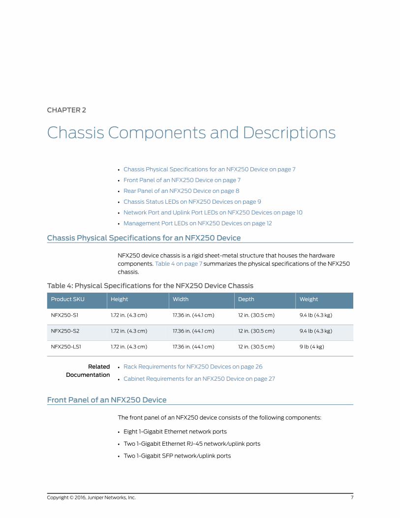
Chassis Physical Specifications for an NFX250 Device
NFX250 device chassis is a rigid sheet-metal structure that houses the hardware
components. Table 4 on page 7 summarizes the physical specifications of the NFX250
chassis.
Table 4: Physical Specifications for the NFX250 Device Chassis
WeightDepthWidthHeightProduct SKU
9.4 lb (4.3 kg)12 in. (30.5 cm)17.36 in. (44.1 cm)1.72 in. (4.3 cm)NFX250-S1
9.4 lb (4.3 kg)12 in. (30.5 cm)17.36 in. (44.1 cm)1.72 in. (4.3 cm)NFX250-S2
9 lb (4 kg)12 in. (30.5 cm)17.36 in. (44.1 cm)1.72 in. (4.3 cm)NFX250-LS1
RelatedDocumentation
Rack Requirements for NFX250 Devices on page 26•
• Cabinet Requirements for an NFX250 Device on page 27
Front Panel of an NFX250 Device
The front panel of an NFX250 device consists of the following components:
• Eight 1-Gigabit Ethernet network ports
• Two 1-Gigabit Ethernet RJ-45 network/uplink ports
• Two 1-Gigabit SFP network/uplink ports
7Copyright © 2016, Juniper Networks, Inc.

• Two 1/10-Gigabit SFP+ uplink ports
• SFP and SFP+ ports Link and Status LEDs
• 1 Mini-USB Type-B Console Port
• 1 RJ-45 Console port
• 1 USB port
• 1-Gigabit Management port
• 4 System Status LEDs
• 3 Port Parameter LEDs
• 1 Mode Button
Figure 2: NFX250 Front Panel Components
7—1— System status LEDs1-Gigabit Ethernet RJ-45 network ports
8—2— Mode buttonSFP and SFP+ ports Link and Status LEDs
9—3— 1/10-Gigabit SFP+ uplink portsMini-USB console port
10—4— 1-Gigabit SFP network/uplink portsConsole port
11—5— 1-Gigabit Ethernet RJ-45 network/uplinkports
USB port
6—1-Gigabit Management port
CAUTION: Donot use theResetbutton to restart the power sequence unless
under the direction of Juniper Networks Technical Assistance Center (JTAC).
RelatedDocumentation
Chassis Status LEDs on NFX250 Devices on page 9•
• Cooling System and Airflow in an NFX250 Device on page 15
• Prevention of Electrostatic Discharge Damage on page 159
• Connecting anNFX250Device to aNetwork forOut-of-BandManagement onpage95
Rear Panel of an NFX250 Device
The rear panel of the NFX250 device consists of the following components (see
Figure 3 on page 9):
Copyright © 2016, Juniper Networks, Inc.8
NFX250 Network Services Platform Hardware Guide

• Ground area
• Electrostatic discharge (ESD) point
• Exhaust vents
• Power switch
• AC power cord inlet
Figure 3: NFX250 Device Switch Rear Panel
4—1— Power switchGround area
5—2— AC power cord inletElectrostatic discharge (ESD) point
3—Exhaust vents
RelatedDocumentation
Front Panel of an NFX250 Device on page 7•
• Cooling System and Airflow in an NFX250 Device on page 15
Chassis Status LEDs on NFX250 Devices
The front panel of an NFX250 device has chassis status LEDs (labeled ALM, SYS,MST
and PH) , next to theMGMT port (see Figure 4 on page 9).
Figure 4: Chassis Status LEDs in an NFX250 Device
3—1— Mode buttonChassis status LEDs (ALM,SYS,MST, andPH)
2—Port parameter LEDs (SPD,DX, and EN)
Table 5 on page 10 describes the chassis status LEDs in NFX250 Device, their colors and
states, and the status they indicate. You can view the colors of the four LEDs remotely
through the CLI by issuing the operational mode command show chassis led.
9Copyright © 2016, Juniper Networks, Inc.
Chapter 2: Chassis Components and Descriptions

Table 5: Chassis Status LEDs in an NFX250 Device
State and DescriptionColorLED Label
There is no alarm or the device is halted.UnlitALM (Alarm)
There is a major alarm.Red
There is a minor alarm.Amber
• On steadily—Junos OS has been loaded on the device.
• Blinking—The device is booting.
• Off—The device is powered off or is halted.
GreenSYS (System)
• On steadily—The device is functioning normally.
• Off—The device is powered off or is halted.
GreenMST (Master)
There is no Network Service Activator transaction.UnlitPH
• On steadily—Network Service Activator transaction issuccessfully completed. That is, the Network ServiceOrchestrator in NFX250 contacted the Network ServiceActivator and provisioned the software image successfully.
• Blinking—NetworkServiceActivator transaction isunderway.
• Off—The device is powered off or is halted.
Green
• On steadily—Network Service Activator transaction isterminated unsuccessfully.
• Blinking—Network Service Activator transaction is waitingfor user input.
Amber
Amajor alarm (red) indicates a critical error condition that requires immediate action.
A minor alarm (amber) indicates a noncritical condition that requires monitoring or
maintenance. A minor alarm left uncheckedmight cause interruption in service or
performance degradation.
All four LEDs can be lit simultaneously.
RelatedDocumentation
Front Panel of an NFX250 Device on page 7•
Network Port and Uplink Port LEDs on NFX250 Devices
Each network port and uplink port on the front panel of an NFX250 has two LEDs that
indicate link activity and port status (see Figure 5 on page 11).
Copyright © 2016, Juniper Networks, Inc.10
NFX250 Network Services Platform Hardware Guide

Figure 5: LEDs on the Network Port
g041
128
Link/Activity
Status
Table 6 on page 11 describes the Link/Activity LED.
Table 6: Link/Activity LED on the Network Ports and Uplink Ports in NFX250 Devices
State and DescriptionColorLED
• Blinking—The port and the link are active, and there is link activity.
• On steadily—The port and the link are active, but there is no link activity.
• Off—The port is not active.
GreenLink/Activity
Figure 6 on page 11 shows the LEDs that indicate the status of one of the three port
parameters—speed, duplexmode, andadministrative status.Use theFactory reset/Mode
buttonon the far right sideof the frontpanel to toggle theStatusLED toshowthedifferent
port parameters. You can tell which port parameter (speed, duplex mode, or
administrative status) is indicated by the Status LED by looking at which port status
mode LED (SPD, DX, or EN) is lit.
Figure 6: Port StatusMode LEDs of an NFX250 Device
3—1— Mode buttonChassis status LEDs (ALM,SYS,MST, andPH)
2—Port parameter LEDs (SPD,DX, and EN)
Table 7 on page 12 describes the Status LED.
11Copyright © 2016, Juniper Networks, Inc.
Chapter 2: Chassis Components and Descriptions

Table 7: Status LED on the Network Ports and Uplink Ports in NFX250 Devices
State and DescriptionPort Parameters
Indicates the speed. The speed indicators for network ports are:
• One blink per second—10 Mbps
• Two blinks per second—100Mbps
• Three blinks per second—1000Mbps
Speed
Indicates the duplex mode. The status indicators are:
• On steadily—Port is set to full-duplex mode.
• Off—Port is set to half-duplex mode.
Duplex mode
Indicates the administrative status. The status indicators are:
• On steadily—Port is administratively enabled.
• Off—Port is administratively disabled.
Administrative status
You can tell which port parameter is indicated by the Status LED on network ports by
issuing the operational mode command show chassis led.
RelatedDocumentation
NFX250 Device Hardware Overview on page 3•
• Front Panel of an NFX250 Device on page 7
Management Port LEDs on NFX250 Devices
Themanagementporton the frontpanelofanNFX250devicehas twoLEDs that indicate
link activity and port status (see Figure 7 on page 12).
Figure 7: LEDs on theManagement Port of an NFX250
2—1— StatusLink/Activity
Table 8 on page 13 describes the Link/Activity LED.
Copyright © 2016, Juniper Networks, Inc.12
NFX250 Network Services Platform Hardware Guide

Table 8: Link/Activity LED on theManagement Port of an NFX250 Device
State and DescriptionColorLED
• Blinking—The port and the link are active, and there is linkactivity.
• On steadily—The port and the link are active, but there is nolink activity.
• Off—The port is not active.
GreenLink/Activity
Table 9 on page 13 describes the Status LED.
Table 9: Status LED on theManagement Port of an NFX250 Device
State and DescriptionColorLED
Indicates the speed. The speed indicators are:
• One blink per second—10 Mbps
• Two blinks per second—100Mbps
• Three blinks per second—1000Mbps
GreenStatus
RelatedDocumentation
• Front Panel of an NFX250 Device on page 7
• Connecting anNFX250Device to aNetwork forOut-of-BandManagement onpage95
13Copyright © 2016, Juniper Networks, Inc.
Chapter 2: Chassis Components and Descriptions

Copyright © 2016, Juniper Networks, Inc.14
NFX250 Network Services Platform Hardware Guide

CHAPTER 3
Cooling System and Airflow
• Cooling System and Airflow in an NFX250 Device on page 15
Cooling System and Airflow in an NFX250 Device
The NFX250 devices have front-to-back airflow. The air intake to cool the chassis is
located on the front of the chassis. Air is pulled into the chassis and pushed toward the
fans, which are built-in. Hot air exhausts from the rear of the chassis. See
Figure 8 on page 15.
Figure 8: Front-to-Back Airflow Through the NFX250 Chassis
RelatedDocumentation
• Rear Panel of an NFX250 Device on page 8
• Prevention of Electrostatic Discharge Damage on page 159
15Copyright © 2016, Juniper Networks, Inc.

Copyright © 2016, Juniper Networks, Inc.16
NFX250 Network Services Platform Hardware Guide

CHAPTER 4
Power Supplies
• Power Supply in NFX250 Devices on page 17
Power Supply in NFX250 Devices
NFX250 devices use a fixed, internal AC power supply. The power supply distributes
different output voltages to the device components according to their voltage
requirements. The power supply is fixed in the chassis and is not field-replaceable.
The power supply has a single AC appliance inlet that requires a dedicated AC power
feed. The AC power cord inlet is on the rear panel of the device.
RelatedDocumentation
• AC Power Supply Specifications for an NFX250 Device on page 31
• AC Power Cord Specifications for an NFX250 Device on page 31
• Connecting AC Power to an NFX250 Device on page 92
17Copyright © 2016, Juniper Networks, Inc.

Copyright © 2016, Juniper Networks, Inc.18
NFX250 Network Services Platform Hardware Guide

PART 2
Site Planning, Preparation, andSpecifications
• Preparation Overview on page 21
• Power Specifications and Requirements on page 31
• Port and Pinout Specifications on page 35
• Transceiver and Cable Specifications on page 41
19Copyright © 2016, Juniper Networks, Inc.

Copyright © 2016, Juniper Networks, Inc.20
NFX250 Network Services Platform Hardware Guide

CHAPTER 5
Preparation Overview
• Site Preparation Checklist for NFX250 Devices on page 21
• Environmental Requirements and Specifications for an NFX250 Device on page 23
• General Site Guidelines on page 24
• Site Electrical Wiring Guidelines on page 24
• Requirements for Mounting an NFX250 Device on a Desktop or Other Level
Surface on page 25
• Requirements for Mounting an NFX250-LS1 Device on aWall on page 25
• Rack Requirements for NFX250 Devices on page 26
• Cabinet Requirements for an NFX250 Device on page 27
• Clearance Requirements for Airflow and Hardware Maintenance for an NFX250
Device on page 28
Site Preparation Checklist for NFX250 Devices
The checklist in Table 10 on page 21 summarizes the tasks you need to performwhen
preparing a site for NFX250 devices installation.
Table 10: Site Preparation Checklist
DatePerformed byFor More InformationItem or Task
Environment
“Environmental Requirements andSpecifications for anNFX250Device”on page 23
Verify that environmental factors such astemperatureandhumiditydonotexceeddevicetolerances.
Power
Measure distance between external powersources and device installation site.
Locate sites for connection of systemgrounding.
“AC Power Supply Specifications foran NFX250 Device” on page 31
Calculate the power consumption andrequirements.
21Copyright © 2016, Juniper Networks, Inc.

Table 10: Site Preparation Checklist (continued)
DatePerformed byFor More InformationItem or Task
Hardware Configuration
“NFX250DeviceHardwareOverview”on page 3
“NFX250 Device Models” on page 4
Choose the number and types of devicess youwant to install.
Rack or Cabinet
“Rack Requirements for NFX250Devices” on page 26
“Cabinet Requirements for anNFX250 Device” on page 27
Verify that your rack or cabinet meets theminimum requirements for the installation ofthe device.
“Clearance Requirements for Airflowand Hardware Maintenance for anNFX250 Device” on page 28
Plan rackor cabinet location, including requiredspace clearances.
Secure the rack or cabinet to the floor andbuilding structure.
Desk
“Requirements for Mounting anNFX250DeviceonaDesktoporOtherLevel Surface” on page 25
Verify that the desk meets the minimumrequirements for the installation of the device.
“Clearance Requirements for Airflowand Hardware Maintenance for anNFX250 Device” on page 28
Verify that there is appropriate clearance in yourselected location.
Wall
“Requirements for Mounting anNFX250-LS1 Device on aWall” onpage 25
Verify that the wall meets the minimumrequirements for the installation of theNFX250-LS1 device.
“Clearance Requirements for Airflowand Hardware Maintenance for anNFX250 Device” on page 28
Verify that there is appropriate clearance in yourselected location.
Cables
Acquire cables and connectors:
• Determine the number of cables neededbased on your planned configuration.
• Review themaximum distance allowed foreachcable.Choose the lengthof cablebasedon the distance between the hardwarecomponents being connected.
Plan the cable routing andmanagement.
Copyright © 2016, Juniper Networks, Inc.22
NFX250 Network Services Platform Hardware Guide
RelatedDocumentation
General Safety Guidelines andWarnings on page 129•
• General Site Guidelines on page 24
• Installing and Connecting an NFX250 Device on page 81
• Mounting an NFX250 Device on page 82
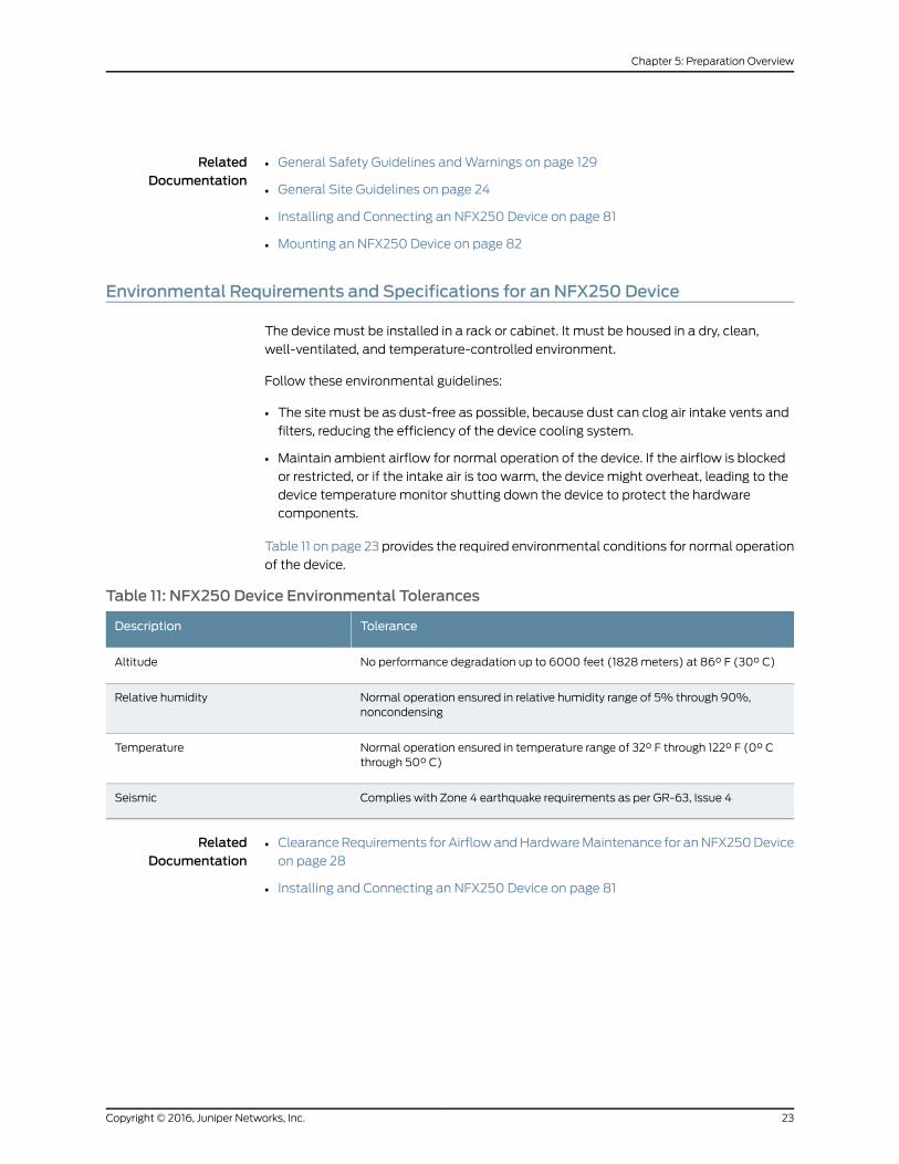
Environmental Requirements and Specifications for an NFX250 Device
The device must be installed in a rack or cabinet. It must be housed in a dry, clean,
well-ventilated, and temperature-controlled environment.
Follow these environmental guidelines:
• The site must be as dust-free as possible, because dust can clog air intake vents and
filters, reducing the efficiency of the device cooling system.
• Maintain ambient airflow for normal operation of the device. If the airflow is blocked
or restricted, or if the intake air is too warm, the device might overheat, leading to the
device temperature monitor shutting down the device to protect the hardware
components.
Table 11 on page 23 provides the required environmental conditions for normal operation
of the device.
Table 11: NFX250 Device Environmental Tolerances
ToleranceDescription
No performance degradation up to 6000 feet (1828meters) at 86° F (30° C)Altitude
Normal operation ensured in relative humidity range of 5% through 90%,noncondensing
Relative humidity
Normal operation ensured in temperature range of 32° F through 122° F (0° Cthrough 50° C)
Temperature
Complies with Zone 4 earthquake requirements as per GR-63, Issue 4Seismic
RelatedDocumentation
ClearanceRequirements for AirflowandHardwareMaintenance for anNFX250Device
on page 28
•
• Installing and Connecting an NFX250 Device on page 81
23Copyright © 2016, Juniper Networks, Inc.
Chapter 5: Preparation Overview

General Site Guidelines
Efficient device operation requires proper site planning andmaintenance and proper
layout of the equipment, rack or cabinet (if used), and wiring closet.
To plan and create an acceptable operating environment for your device and prevent
environmentally caused equipment failures:
• Keep the area around the chassis free from dust and conductive material, such as
metal flakes.
• Followprescribedairflowguidelines toensure that thecoolingsystemfunctionsproperly
and that exhaust from other equipment does not blow into the intake vents of the
device.
• Follow the prescribed electrostatic discharge (ESD) prevention procedures to prevent
damaging the equipment. Static discharge can cause components to fail completely
or intermittently over time.
• Install the device in a secure area, so that only authorized personnel can access the
device.
RelatedDocumentation
Prevention of Electrostatic Discharge Damage on page 159•
Site ElectricalWiring Guidelines
Table 12 on page 24 describes the factors youmust considerwhile planning the electrical
wiring at your site.
WARNING: It is particularly important to provide a properly grounded andshielded environment and to use electrical surge-suppression devices.
Table 12: Site ElectricalWiring Guidelines
GuidelinesSiteWiring Factor
If your site experiences any of the following problems, consultexperts in electrical surge suppression and shielding:
• Improperly installedwirescause radio frequency interference(RFI).
• Damage from lightning strikes occurs when wires exceedrecommended distances or pass between buildings.
• Electromagnetic pulses (EMPs) caused by lightning damageunshielded conductors and electronic devices.
Signaling limitations
Copyright © 2016, Juniper Networks, Inc.24
NFX250 Network Services Platform Hardware Guide

Table 12: Site ElectricalWiring Guidelines (continued)
GuidelinesSiteWiring Factor
To reduceor eliminateRFI fromyour sitewiring, do the following:
• Usea twisted-pair cablewithagooddistributionofgroundingconductors.
• If you must exceed the recommended distances, use ahigh-quality twisted-pair cable with one ground conductorfor each data signal when applicable.
Radio frequency interference
If your site is susceptible to problems with electromagneticcompatibility (EMC), particularly from lightning or radiotransmitters, seek expert advice.
Some of the problems caused by strong sources ofelectromagnetic interference (EMI) are:
• Destruction of the signal drivers and receivers in the device
• Electrical hazards as a result of power surges conductedoverthe lines into the equipment
Electromagnetic compatibility
RelatedDocumentation
General Safety Guidelines andWarnings on page 129•
• General Electrical Safety Guidelines andWarnings on page 157
• Prevention of Electrostatic Discharge Damage on page 159
Requirements for Mounting an NFX250 Device on a Desktop or Other Level Surface
You can install NFX250 device on a desktop or other such level surface, by attaching the
four rubber feet (provided) to the bottom of the chassis.
When choosing a location, allow at least 6 in. (15.2 cm) of clearance between the front
and back of the chassis and adjacent equipment or walls.
Ensure that the desktop or other level surface on which the device is installed is stable
and securely supported.
RelatedDocumentation
ClearanceRequirements for AirflowandHardwareMaintenance for anNFX250Device
on page 28
•
Requirements for Mounting an NFX250-LS1 Device on aWall
You can install the NFX250-LS1 device on a wall. When choosing a location, allow at
least 6 in. (15.2 cm) of clearance between the front and back of the chassis and adjacent
equipment or walls.
Ensure that the wall onto which the device is installed is stable and securely supported.
If you are mounting the device in sheetrock (wall board with a gypsum plaster core) or
in wall board not backed by wall studs, use hollow wall anchors capable of supporting
25Copyright © 2016, Juniper Networks, Inc.
Chapter 5: Preparation Overview
the combined weight of two fully loaded chassis. Insert the screws into wall studs
wherever possible to provide added support for the chassis.
Use the wall-mount kit from Juniper Networks to mount the device on a wall. The
wall-mount kit is not part of the standard package andmust be ordered separately.
RelatedDocumentation
ClearanceRequirements for AirflowandHardwareMaintenance for anNFX250Device
on page 28
•
• Mounting an NFX250-LS1 Device on aWall on page 83
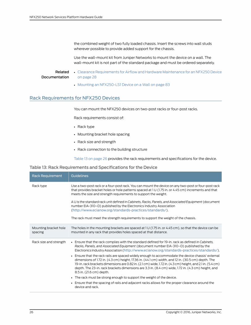
Rack Requirements for NFX250 Devices
You canmount the NFX250 devices on two-post racks or four-post racks.
Rack requirements consist of:
• Rack type
• Mounting bracket hole spacing
• Rack size and strength
• Rack connection to the building structure
Table 13 on page 26 provides the rack requirements and specifications for the device.
Table 13: Rack Requirements and Specifications for the Device
GuidelinesRack Requirement
Use a two-post rack or a four-post rack. You canmount the device on any two-post or four-post rackthat provides bracket holes or hole patterns spaced at 1 U (1.75 in. or 4.45 cm) increments and thatmeets the size and strength requirements to support the weight.
AU is the standard rack unit defined inCabinets, Racks, Panels, andAssociated Equipment (documentnumber EIA-310–D) published by the Electronics Industry Association(http://www.ecianow.org/standards-practices/standards/).
The rack must meet the strength requirements to support the weight of the chassis.
Rack type
The holes in the mounting brackets are spaced at 1 U (1.75 in. or 4.45 cm), so that the device can bemounted in any rack that provides holes spaced at that distance.
Mounting bracket holespacing
• Ensure that the rack complies with the standard defined for 19-in. rack as defined in Cabinets,Racks, Panels, and Associated Equipment (document number EIA-310–D) published by theElectronics IndustryAssociation(http://www.ecianow.org/standards-practices/standards/).
• Ensure that the rack rails are spaced widely enough to accommodate the device chassis' externaldimensions of 1.72 in. (4.3 cm) height, 17.36 in. (44.1 cm) width, and 12 in. (30.5 cm) depth. The19-in. rackbracketsdimensionsare0.82 in. (2.1 cm)wide, 1.72 in. (4.3 cm)height, and2.1 in. (5.4 cm)depth. The 23-in. rack brackets dimensions are 3.3 in. (8.4 cm) wide, 1.72 in. (4.3 cm) height, and8.5 in. (21.6 cm) depth.
• The rack must be strong enough to support the weight of the device.
• Ensure that the spacing of rails and adjacent racks allows for the proper clearance around thedevice and rack.
Rack size and strength
Copyright © 2016, Juniper Networks, Inc.26
NFX250 Network Services Platform Hardware Guide

Table 13: Rack Requirements and Specifications for the Device (continued)
GuidelinesRack Requirement
• Secure the rack to the building structure.
• If earthquakes are a possibility in your geographical area, secure the rack to the floor.
• Secure the rack to the ceiling brackets as well as wall or floor brackets for maximum stability.
Rack connection tobuilding structure
One pair ofmounting brackets formounting the device on two posts of a rack is supplied
with each device. For mounting the device on four posts of a rack or cabinet, you can
order a four-post rack-mount kit separately.
RelatedDocumentation
Chassis Physical Specifications for an NFX250 Device on page 7•
• ClearanceRequirements for AirflowandHardwareMaintenance for anNFX250Device
on page 28
• Rack-Mounting and Cabinet-MountingWarnings on page 140
• Mounting an NFX250 Device on Two Posts in a Rack on page 86
• Mounting an NFX250 Device on Four Posts in a Rack or Cabinet on page 88
Cabinet Requirements for an NFX250 Device
You canmount the NFX250 device in an enclosure or cabinet that contains a four-post
19-in. open rack as defined in Cabinets, Racks, Panels, and Associated Equipment
(document number EIA-310-D) published by the Electronics Industry Association.
Cabinet requirements consist of:
• Cabinet size and clearance
• Cabinet airflow requirements
Table 14onpage27provides the cabinet requirements and specifications for theNFX250
device.
Table 14: Cabinet Requirements for the NFX250 Device
GuidelinesCabinet Requirement
Theminimumcabinet size foraccommodatinganNFX250device is36 in. (91.4cm)deep. Large cabinets improve airflow and reduce the chance of overheating.
Cabinet size and clearance
27Copyright © 2016, Juniper Networks, Inc.
Chapter 5: Preparation Overview

Table 14: Cabinet Requirements for the NFX250 Device (continued)
GuidelinesCabinet Requirement
Whenyoumount the switch inacabinet, ensure that ventilation through thecabinetis sufficient to prevent overheating.
• Ensure that the cool air supply you provide through the cabinet adequatelydissipates the thermal output of the switch (or switches).
• Ensure that the cabinet allows the chassis hot exhaust air to exit the cabinetwithout recirculating into the switch. An open cabinet (without a top or doors)that employs hot air exhaust extraction from the top allows the best airflowthrough the chassis. If the cabinet contains a top or doors, perforations in theseelements assist with removing the hot air exhaust.
• Install the switch in the cabinet in a way that maximizes the open space on theside of the chassis that has the hot air exhaust.
• Route and dress all cables to minimize the blockage of airflow to and from thechassis.
• Ensure that the spacing of rails and adjacent cabinets allows for the properclearance around the switch and cabinet.
• A cabinet larger than theminimum required provides better airflow and reducesthe chance of overheating.
Cabinet airflow requirements
RelatedDocumentation
ClearanceRequirements for AirflowandHardwareMaintenance for anNFX250Device
on page 28
•
• Rack Requirements for NFX250 Devices on page 26
ClearanceRequirements forAirflowandHardwareMaintenance foranNFX250Device
When planning the site for installing an NFX250 device, youmust allow sufficient
clearance around the installed chassis (see Figure 9 on page 29).
Copyright © 2016, Juniper Networks, Inc.28
NFX250 Network Services Platform Hardware Guide
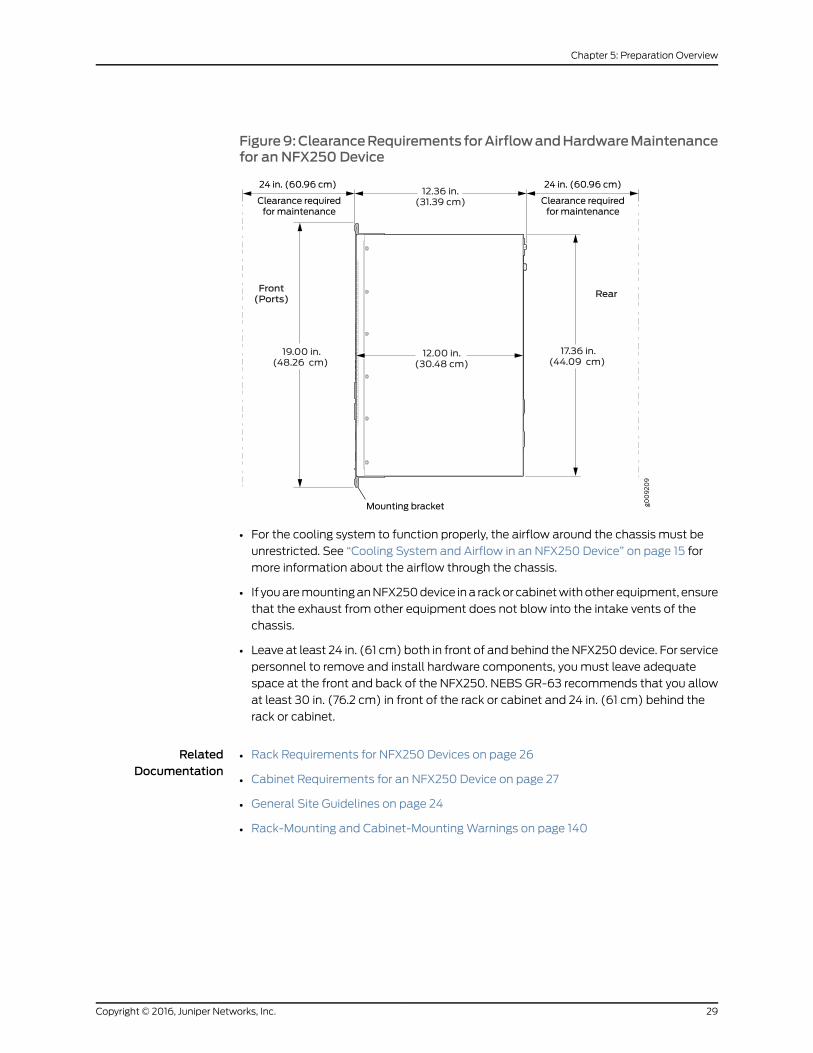
Figure9:ClearanceRequirements forAirflowandHardwareMaintenancefor an NFX250 Device
• For the cooling system to function properly, the airflow around the chassis must be
unrestricted. See “Cooling System and Airflow in an NFX250 Device” on page 15 for
more information about the airflow through the chassis.
• If youaremountinganNFX250device ina rackor cabinetwithother equipment, ensure
that the exhaust from other equipment does not blow into the intake vents of the
chassis.
• Leave at least 24 in. (61 cm) both in front of and behind theNFX250 device. For service
personnel to remove and install hardware components, youmust leave adequate
space at the front and back of the NFX250. NEBS GR-63 recommends that you allow
at least 30 in. (76.2 cm) in front of the rack or cabinet and 24 in. (61 cm) behind the
rack or cabinet.
RelatedDocumentation
• Rack Requirements for NFX250 Devices on page 26
• Cabinet Requirements for an NFX250 Device on page 27
• General Site Guidelines on page 24
• Rack-Mounting and Cabinet-MountingWarnings on page 140
29Copyright © 2016, Juniper Networks, Inc.
Chapter 5: Preparation Overview

Copyright © 2016, Juniper Networks, Inc.30
NFX250 Network Services Platform Hardware Guide
CHAPTER 6
Power Specifications and Requirements
• AC Power Supply Specifications for an NFX250 Device on page 31
• AC Power Cord Specifications for an NFX250 Device on page 31
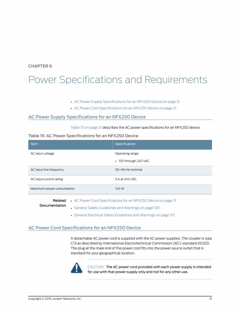
AC Power Supply Specifications for an NFX250 Device
Table 15 on page 31 describes the AC power specifications for an NFX250 device.
Table 15: AC Power Specifications for an NFX250 Device
SpecificationItem
Operating range:
• 100 through 240 VAC
AC input voltage
50–60 Hz nominalAC input line frequency
3 A at 240 VACAC input current rating
140WMaximum power consumption
RelatedDocumentation
AC Power Cord Specifications for an NFX250 Device on page 31•
• General Safety Guidelines andWarnings on page 129
• General Electrical Safety Guidelines andWarnings on page 157
AC Power Cord Specifications for an NFX250 Device
A detachable AC power cord is supplied with the AC power supplies. The coupler is type
C13 as described by International Electrotechnical Commission (IEC) standard 60320.
The plug at the male end of the power cord fits into the power source outlet that is
standard for your geographical location.
CAUTION: The AC power cord provided with each power supply is intendedfor use with that power supply only and not for any other use.
31Copyright © 2016, Juniper Networks, Inc.

NOTE: In North America, AC power cordsmust not exceed 4.5meters(approximately 14.75 feet) in length, to complywith National Electrical Code(NEC) Sections 400-8 (NFPA 75, 5-2.2) and 210-52 and Canadian ElectricalCode (CEC) Section 4-010(3). The cords supplied with the switch are incompliance.
Table 16 on page 32 gives the AC power cord specifications for the countries and regions
listed in the table.
Table 16: AC Power Cord Specifications
Juniper Model NumberPlug StandardsElectrical SpecificationsCountry/Region
CBL-EX-PWR-C13-ARIRAM 2073 Type RA/3250 VAC, 10 A, 50 HzArgentina
CBL-EX-PWR-C13-AUAS/NZZS 3112 Type SAA/3250 VAC, 10 A, 50 HzAustralia
CBL-EX-PWR-C13-BRNBR 14136 Type BR/3250 VAC, 10 A, 50 HzBrazil
CBL-EX-PWR-C13-CHGB 1002-1996 Type PRC/3250 VAC, 10 A, 50 HzChina
CBL-EX-PWR-C13-EUCEE (7) VII Type VIIG250 VAC, 10 A, 50 HzEurope (except Italy,Switzerland, and UnitedKingdom)
CBL-EX-PWR-C13-INIS 1293 Type IND/3250 VAC, 10 A, 50 HzIndia
CBL-EX-PWR-C13-ILSI 32/1971 Type IL/3G250 VAC, 10 A, 50 HzIsrael
CBL-EX-PWR-C13-ITCEI 23-16 Type I/3G250 VAC, 10 A, 50 HzItaly
CBL-EX-PWR-C13-JPSS-00259 Type VCTF125 VAC, 12 A, 50 Hz or 60 HzJapan
CBL-EX-PWR-C13-KRCEE (7) VII Type VIIGK250VAC, 10A, 50Hz or 60HzKorea
CBL-EX-PWR-C13-USNEMA 5-15 Type N5-15125 VAC, 13 A, 60 HzNorth America
CBL-EX-PWR-C13-SASABS 164/1:1992 Type ZA/13250 VAC, 10 A, 50 HzSouth Africa
CBL-EX-PWR-C13-SZSEV 6534-2 Type 12G250 VAC, 10 A, 50 HzSwitzerland
CBL-EX-PWR-C13-TWNEMA 5-15P Type N5-15P125 VAC, 11 A and 15 A, 50 HzTaiwan
CBL-EX-PWR-C13-UKBS 1363/A Type BS89/13250 VAC, 10 A, 50 HzUnited Kingdom
Figure 10 on page 33 illustrates the plug on the power cord for some of the countries or
regions listed in Table 16 on page 32.
Copyright © 2016, Juniper Networks, Inc.32
NFX250 Network Services Platform Hardware Guide

Figure 10: AC Plug Types
RelatedDocumentation
• General Safety Guidelines andWarnings on page 129
• General Electrical Safety Guidelines andWarnings on page 157
• Prevention of Electrostatic Discharge Damage on page 159
33Copyright © 2016, Juniper Networks, Inc.
Chapter 6: Power Specifications and Requirements

Copyright © 2016, Juniper Networks, Inc.34
NFX250 Network Services Platform Hardware Guide

CHAPTER 7
Port and Pinout Specifications
• Mini-USB Type-B Console Port Specifications for an NFX250 Device on page 35
• Console Port Connector Pinouts for NFX250 Devices on page 36
• USB Port Specifications for an NFX250 Device on page 37
• Management Port Connector Pinout Information for an NFX250 Device on page 37
• Network Port Connector Pinout Information for an NFX250 Device on page 38
• RJ-45 toDB-9SerialPortAdapterPinout Information for anNFX250Deviceonpage39
Mini-USB Type-B Console Port Specifications for an NFX250 Device
NFX250 Device has two: an RJ-45 port, and a Mini-USB port.
By default, the RJ-45 port is set as the active console port. It can display all the early boot
and low-level message output and you can access the device through this port in the
debugger prompt.
The Mini-USB port is the passive console port. You can change the status of the port to
activeor passiveusing theport-typeconfiguration statement. SeeConfiguring theConsole
Port Type (CLI Procedure).
TheMini-USB console port uses aMini-B plug (5-pin) connector to connect to a console
management device. The default baud rate for the console port is 9600 baud.
Table 17 on page 35 provides the pinout information of the Mini-USB Type-B console
port.
Table 17: Mini-USB Type-B Console Port Pinout Information for NFX250 Devices
DescriptionSignalPin
+5 VDCVCC1
Data -D-2
Data +D+3
May be N/C, GND or used as an attached device presence indicatorN/CX
35Copyright © 2016, Juniper Networks, Inc.

Table 17: Mini-USB Type-B Console Port Pinout Information for NFX250 Devices (continued)
DescriptionSignalPin
GroundGND4
RelatedDocumentation
See NFX250 Device Hardware Overview on page 3•
• Configuring the Console Port Type (CLI Procedure)
Console Port Connector Pinouts for NFX250 Devices
Theconsoleport (labeledCON) is anRS-232serial interface thatusesanRJ-45connector
to connect to a console management device. The default baud rate for the console port
is 9600 baud.
Table 18 on page 36 provides the pinout information for the RJ-45 console connector.
An RJ-45 cable and RJ-45 to DB-9 adapter are supplied with the NFX250 device.
NOTE: If your laptopor PCdoes not have aDB-9male connector pin and youwant to connect your laptop or PC directly to an NFX250 device, use acombination of theRJ-45 cable andRJ-45 toDB-9adapter suppliedwith thedevice and a USB to DB-9male adapter. Youmust provide the USB to DB-9male adapter.
Table 18: Console Port Connector Pinouts for the NFX250 Device
DescriptionSignalPin
Request to sendRTS Output1
Data terminal readyDTR Output2
Transmit dataTxD Output3
Signal groundSignal Ground4
Signal groundSignal Ground5
Receive dataRxD Input6
Data carrier detectDCD Input7
Clear to sendCTS Input8
RelatedDocumentation
Connecting an NFX250 Device to a Management Console on page 96•
Copyright © 2016, Juniper Networks, Inc.36
NFX250 Network Services Platform Hardware Guide

USB Port Specifications for an NFX250 Device
The following Juniper Networks USB flash drives have been tested and are officially
supported for the USB port in the NFX250 devices:
• RE-USB-1G-S—1-gigabyte (GB) USB flash drive
• RE-USB-2G-S—2-GB USB flash drive
• RE-USB-4G-S—4-GB USB flash drive
CAUTION: AnyUSBmemoryproduct not listedas supported for theNFX250device has not been tested by Juniper Networks. The use of any unsupportedUSBmemory product could expose your device to unpredictable behavior.JuniperNetworksTechnicalAssistanceCenter (JTAC)canprovideonly limitedsupport for issues relatedtounsupportedhardware.Westrongly recommendthat you use only supported USB flash drives.
CAUTION: Remove the USB flash drive before upgrading Junos OS orrebooting a NFX250 device. Failure to do so could expose your device tounpredictable behavior.
NOTE: Executing the request system snapshot CLI command on a NFX250
device requires an external USB flash drive with at least 4 GB of free space.We recommend using the RE-USB-4G-S flash drive.
NOTE: USB flash drives usedwith theNFX250devicemust support USB 2.0or later.
RelatedDocumentation
Front Panel of an NFX250 Device on page 7•
Management Port Connector Pinout Information for an NFX250 Device
The 1000BASE-TRJ-45managementportonanNFX250deviceusesanRJ-45connector
to connect to amanagement device for out-of-bandmanagement.
Table 19 on page 38 provides the pinout information of the RJ-45management port
connector.
37Copyright © 2016, Juniper Networks, Inc.
Chapter 7: Port and Pinout Specifications

Table 19: RJ-45Management Port Connector Pinouts for the NFX250 Devices
DescriptionSignalPin
Transmit/receive data pair 1TRP1+1
Transmit/receive data pair 1TRP1–2
Transmit/receive data pair 2TRP2+3
Transmit/receive data pair 3TRP3+4
Transmit/receive data pair 3TRP3–5
Transmit/receive data pair 2TRP2–6
Transmit/receive data pair 4TRP4+7
Transmit/receive data pair 4TRP4–8
RelatedDocumentation
Management Port LEDs on NFX250 Devices on page 12•
Network Port Connector Pinout Information for an NFX250 Device
A network port on an NFX250 device uses an RJ-45 connector to connect to a device.
The port uses an autosensing RJ-45 connector to support a 10/100/1000Base-T
connection. Two LEDs on the port indicate link/activity on the port and the port status.
See “Network Port and Uplink Port LEDs on NFX250 Devices” on page 10.
Table 20 on page 38 provides the pinout information for the RJ-45 connector. An RJ-45
cable, with a connector attached, is supplied with the switch.
Table 20: Network Port Connector Pinout Information for NFX250 Devices
DescriptionSignalPin
Transmit/receive data pair 1
Negative Vport (in PoEmodels)
TRP1+1
Transmit/receive data pair 1
Negative Vport (in PoEmodels)
TRP1-2
Transmit/receive data pair 2
Positive Vport (in PoEmodels)
TRP2+3
Transmit/receive data pair 3TRP3+4
Copyright © 2016, Juniper Networks, Inc.38
NFX250 Network Services Platform Hardware Guide
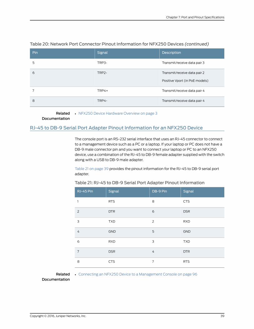
Table 20: Network Port Connector Pinout Information for NFX250 Devices (continued)
DescriptionSignalPin
Transmit/receive data pair 3TRP3-5
Transmit/receive data pair 2
Positive Vport (in PoEmodels)
TRP2-6
Transmit/receive data pair 4TRP4+7
Transmit/receive data pair 4TRP4-8
RelatedDocumentation
NFX250 Device Hardware Overview on page 3•
RJ-45 to DB-9 Serial Port Adapter Pinout Information for an NFX250 Device
The console port is an RS-232 serial interface that uses an RJ-45 connector to connect
to amanagement device such as a PC or a laptop. If your laptop or PC does not have a
DB-9male connector pin and you want to connect your laptop or PC to an NFX250
device, use a combination of the RJ-45 to DB-9 female adapter suppliedwith the switch
along with a USB to DB-9male adapter.
Table 21 on page 39 provides the pinout information for the RJ-45 to DB-9 serial port
adapter.
Table 21: RJ-45 to DB-9 Serial Port Adapter Pinout Information
SignalDB-9 PinSignalRJ-45 Pin
CTS8RTS1
DSR6DTR2
RXD2TXD3
GND5GND4
TXD3RXD6
DTR4DSR7
RTS7CTS8
RelatedDocumentation
• Connecting an NFX250 Device to a Management Console on page 96
39Copyright © 2016, Juniper Networks, Inc.
Chapter 7: Port and Pinout Specifications

Copyright © 2016, Juniper Networks, Inc.40
NFX250 Network Services Platform Hardware Guide

CHAPTER 8
Transceiver and Cable Specifications
• Pluggable Transceivers Supported on NFX250 Devices on page 41
• SFP+ Direct Attach Cables for NFX250 Devices on page 66
• Cable Specifications for Console and Management Connections for the NFX250
Devices on page 69
• Understanding NFX250 Devices Fiber-Optic Cable Signal Loss, Attenuation, and
Dispersion on page 70
• Calculating the Fiber-Optic Cable Power Budget for an NFX250 Device on page 71
• Calculating the Fiber-Optic Cable Power Margin for an NFX250 Device on page 72
Pluggable Transceivers Supported on NFX250 Devices
Uplink module ports on NFX250 devices support SFP and SFP+ transceivers. This topic
describes the optical interfaces supported for those transceivers. It also lists the copper
interface supported for the SFP transceivers.
NOTE: We recommend that you use only optical transceivers and opticalconnectors purchased from Juniper Networks with your Juniper Networksdevice.
CAUTION: If you face a problem running a Juniper Networks device that usesa third-partyopticor cable, the JuniperNetworksTechnicalAssistanceCenter(JTAC) can help you diagnose the source of the problem. Your JTAC engineermight recommendthatyoucheckthethird-partyopticorcableandpotentiallyreplace it with an equivalent Juniper Networks optic or cable that is qualifiedfor the device.
The tables in this topicdescribe theoptical interface support over single-mode fiber-optic
(SMF) andmultimode fiber-optic (MMF) cables and over the copper interface for SFP
transceivers:
• Table22onpage42—Optical interfacesupport andcopper interfacesupport forGigabit
Ethernet SFP transceivers in NFX250 devices.
41Copyright © 2016, Juniper Networks, Inc.

• Table 23onpage62—Optical interface support forGigabit EthernetSFP+ transceivers.
Table 22: Optical Interface Support and Copper Interface Support for Gigabit Ethernet SFPTransceivers in NFX250 Devices
ValueSpecificationEthernet Standard
EX-SFP-1GE-TModel number1000BASE-T
10/100/1000MbpsRate
RJ-45Connector type
–Transmitter wavelength
–Minimum launch power
–Maximum launch power
–Minimum receiver sensitivity
–Maximum input power
–Core/Cladding size
–Modal bandwidth
100m (328 ft)Distance
Junos OS for NFX250 Devices, Release 15.1X53-D40 or laterSoftware required
YesSupport for Virtual Chassisconfiguration
Copyright © 2016, Juniper Networks, Inc.42
NFX250 Network Services Platform Hardware Guide
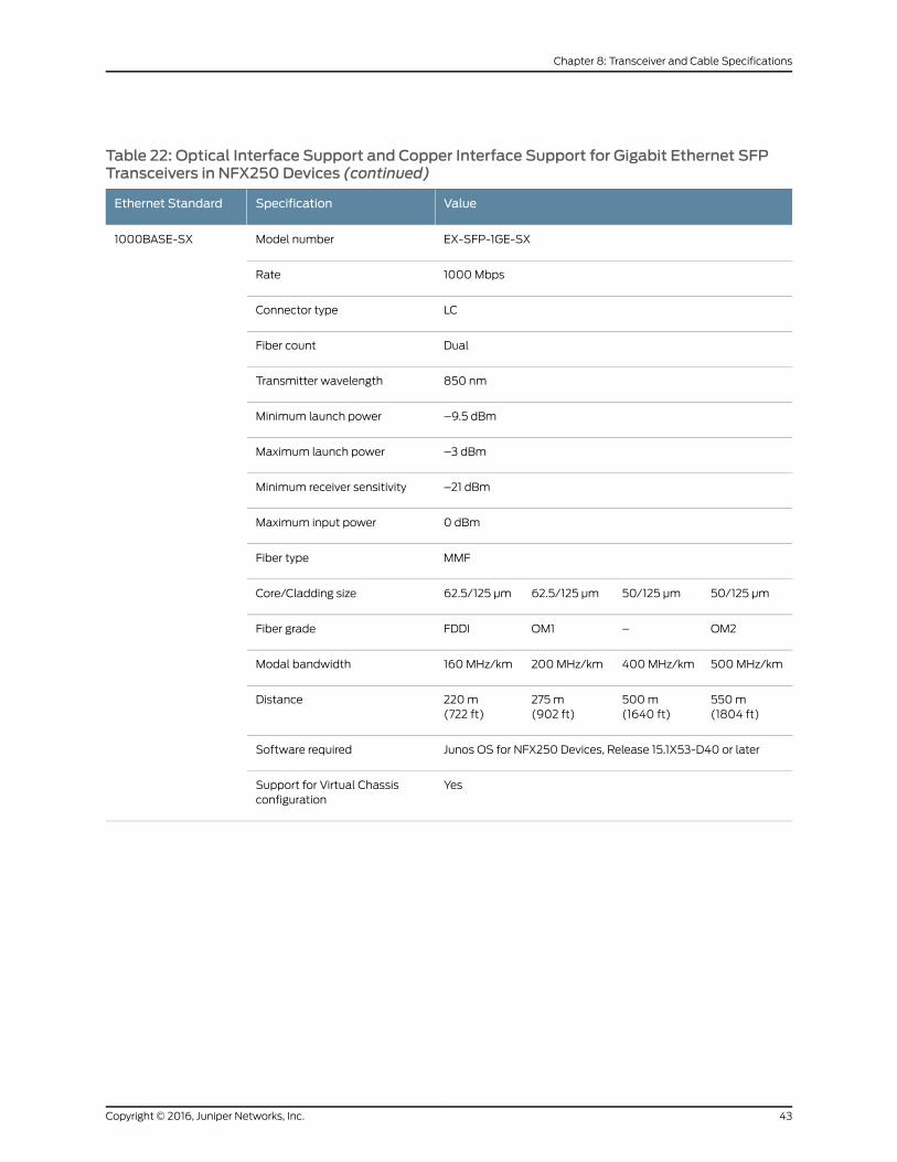
Table 22: Optical Interface Support and Copper Interface Support for Gigabit Ethernet SFPTransceivers in NFX250 Devices (continued)
ValueSpecificationEthernet Standard
EX-SFP-1GE-SXModel number1000BASE-SX
1000MbpsRate
LCConnector type
DualFiber count
850 nmTransmitter wavelength
–9.5 dBmMinimum launch power
–3 dBmMaximum launch power
–21 dBmMinimum receiver sensitivity
0 dBmMaximum input power
MMFFiber type
50/125 µm50/125 µm62.5/125 µm62.5/125 µmCore/Cladding size
OM2–OM1FDDIFiber grade
500MHz/km400MHz/km200MHz/km160MHz/kmModal bandwidth
550m(1804 ft)
500m(1640 ft)
275m(902 ft)
220m(722 ft)
Distance
Junos OS for NFX250 Devices, Release 15.1X53-D40 or laterSoftware required
YesSupport for Virtual Chassisconfiguration
43Copyright © 2016, Juniper Networks, Inc.
Chapter 8: Transceiver and Cable Specifications

Table 22: Optical Interface Support and Copper Interface Support for Gigabit Ethernet SFPTransceivers in NFX250 Devices (continued)
ValueSpecificationEthernet Standard
EX-SFP-1GE-SX-ETModel number1000BASE-SX-ET
1000MbpsRate
LCConnector type
DualFiber count
850 nmTransmitter wavelength
–9.5 dBmMinimum launch power
–3 dBmMaximum launch power
–21 dBmMinimum receiver sensitivity
0 dBmMaximum input power
MMFFiber type
50/125 µm50/125 µm62.5/125 µm62.5/125 µmCore/Cladding size
OM2–OM1FDDIFiber grade
500MHz/km400MHz/km200MHz/km160MHz/kmModal bandwidth
550m(1804 ft)
500m(1640 ft)
275m(902 ft)
220m(722 ft)
Distance
Junos OS for NFX250 Devices, Release 15.1X53-D40 or laterSoftware required
YesSupport for Virtual Chassisconfiguration
Copyright © 2016, Juniper Networks, Inc.44
NFX250 Network Services Platform Hardware Guide

Table 22: Optical Interface Support and Copper Interface Support for Gigabit Ethernet SFPTransceivers in NFX250 Devices (continued)
ValueSpecificationEthernet Standard
EX-SFP-1GE-LXModel number1000BASE-LX
1000MbpsRate
LCConnector type
DualFiber count
1310 nmTransmitter wavelength
–9.5 dBmMinimum launch power
–3 dBmMaximum launch power
–25 dBmMinimum receiver sensitivity
–3 dBmMaximum input power
SMFFiber type
9/125 µmCore/Cladding size
–Modal bandwidth
10 km (6.2 miles)Distance
Junos OS for NFX250 Devices, Release 15.1X53-D40 or laterSoftware required
YesSupport for Virtual Chassisconfiguration
45Copyright © 2016, Juniper Networks, Inc.
Chapter 8: Transceiver and Cable Specifications

Table 22: Optical Interface Support and Copper Interface Support for Gigabit Ethernet SFPTransceivers in NFX250 Devices (continued)
ValueSpecificationEthernet Standard
EX-SFP-GE10KT13R14Model number1000BASE-BX-U
1000MbpsRate
LCConnector type
SingleFiber count
1310 nmTransmitter wavelength
1490 nmReceiver wavelength
–9 dBmMinimum launch power
–3 dBmMaximum launch power
–30 dBmMinimum receiver sensitivity
–3 dBmMaximum input power
SMFFiber type
9/125 µmCore/Cladding size
–Modal bandwidth
10 km (6.2 miles)Distance
Junos OS for NFX250 Devices, Release 15.1X53-D40 or laterSoftware required
YesSupport for Virtual Chassisconfiguration
Copyright © 2016, Juniper Networks, Inc.46
NFX250 Network Services Platform Hardware Guide

Table 22: Optical Interface Support and Copper Interface Support for Gigabit Ethernet SFPTransceivers in NFX250 Devices (continued)
ValueSpecificationEthernet Standard
EX-SFP-GE10KT14R13Model number1000BASE-BX-D
1000MbpsRate
LCConnector type
SingleFiber count
1490 nmTransmitter wavelength
1310 nmReceiver wavelength
–9 dBmMinimum launch power
–3 dBmMaximum launch power
–30 dBmMinimum receiver sensitivity
–3 dBmMaximum input power
SMFFiber type
9/125 µmCore/Cladding size
–Modal bandwidth
10 km (6.2 miles)Distance
Junos OS for NFX250 Devices, Release 15.1X53-D40 or laterSoftware required
YesSupport for Virtual Chassisconfiguration
47Copyright © 2016, Juniper Networks, Inc.
Chapter 8: Transceiver and Cable Specifications

Table 22: Optical Interface Support and Copper Interface Support for Gigabit Ethernet SFPTransceivers in NFX250 Devices (continued)
ValueSpecificationEthernet Standard
EX-SFP-GE10KT13R15Model number1000BASE-BX-U
1000MbpsRate
LCConnector type
SingleFiber count
1310 nmTransmitter wavelength
1550 nmReceiver wavelength
–9 dBmMinimum launch power
–3 dBmMaximum launch power
–21 dBmMinimum receiver sensitivity
–3 dBmMaximum input power
SMFFiber type
9/125 µmCore/Cladding size
–Modal bandwidth
10 km (6.2 miles)Distance
Junos OS for NFX250 Devices, Release 15.1X53-D40 or laterSoftware required
YesSupport for Virtual Chassisconfiguration
Copyright © 2016, Juniper Networks, Inc.48
NFX250 Network Services Platform Hardware Guide
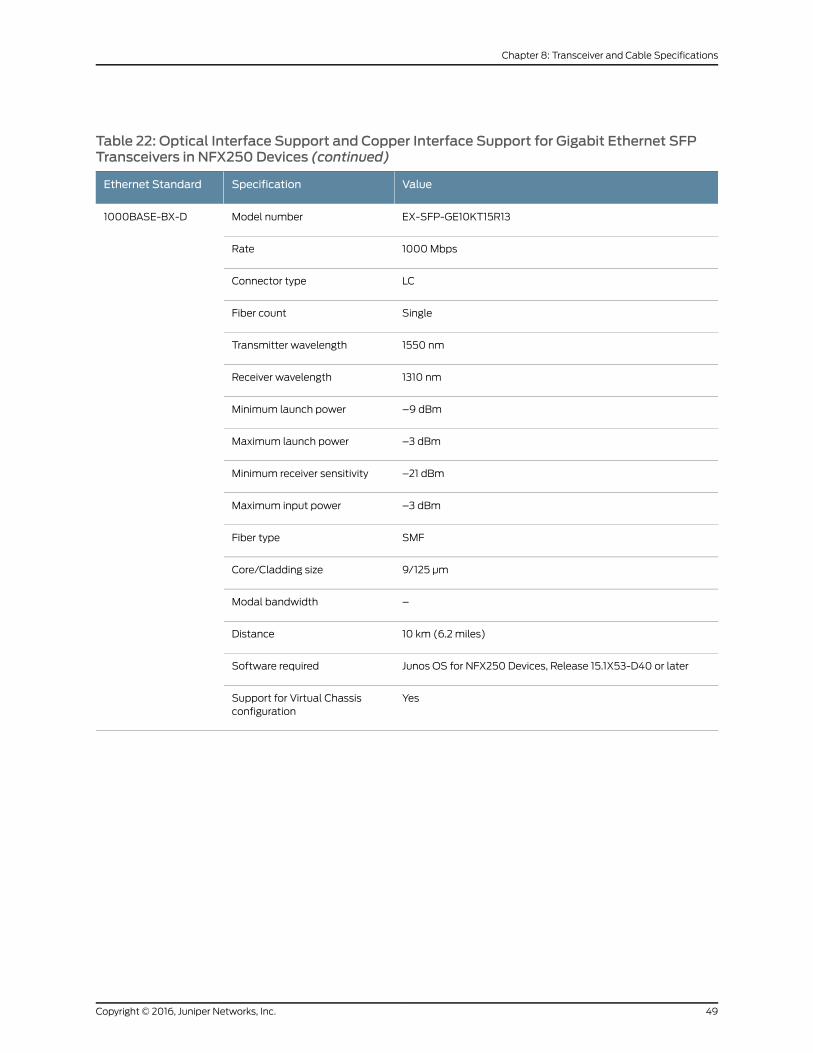
Table 22: Optical Interface Support and Copper Interface Support for Gigabit Ethernet SFPTransceivers in NFX250 Devices (continued)
ValueSpecificationEthernet Standard
EX-SFP-GE10KT15R13Model number1000BASE-BX-D
1000MbpsRate
LCConnector type
SingleFiber count
1550 nmTransmitter wavelength
1310 nmReceiver wavelength
–9 dBmMinimum launch power
–3 dBmMaximum launch power
–21 dBmMinimum receiver sensitivity
–3 dBmMaximum input power
SMFFiber type
9/125 µmCore/Cladding size
–Modal bandwidth
10 km (6.2 miles)Distance
Junos OS for NFX250 Devices, Release 15.1X53-D40 or laterSoftware required
YesSupport for Virtual Chassisconfiguration
49Copyright © 2016, Juniper Networks, Inc.
Chapter 8: Transceiver and Cable Specifications
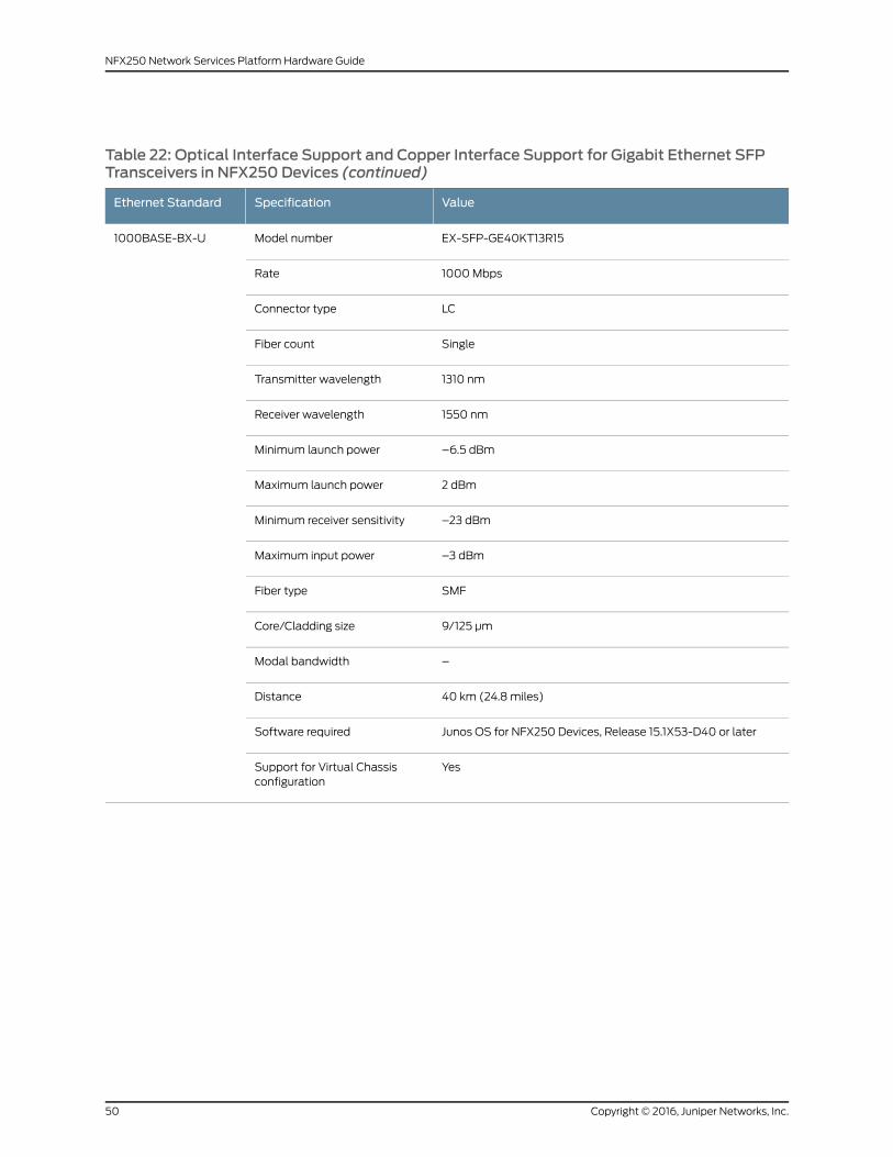
Table 22: Optical Interface Support and Copper Interface Support for Gigabit Ethernet SFPTransceivers in NFX250 Devices (continued)
ValueSpecificationEthernet Standard
EX-SFP-GE40KT13R15Model number1000BASE-BX-U
1000MbpsRate
LCConnector type
SingleFiber count
1310 nmTransmitter wavelength
1550 nmReceiver wavelength
–6.5 dBmMinimum launch power
2 dBmMaximum launch power
–23 dBmMinimum receiver sensitivity
–3 dBmMaximum input power
SMFFiber type
9/125 µmCore/Cladding size
–Modal bandwidth
40 km (24.8 miles)Distance
Junos OS for NFX250 Devices, Release 15.1X53-D40 or laterSoftware required
YesSupport for Virtual Chassisconfiguration
Copyright © 2016, Juniper Networks, Inc.50
NFX250 Network Services Platform Hardware Guide

Table 22: Optical Interface Support and Copper Interface Support for Gigabit Ethernet SFPTransceivers in NFX250 Devices (continued)
ValueSpecificationEthernet Standard
EX-SFP-GE40KT15R13Model number1000BASE-BX-D
1000MbpsRate
LCConnector type
SingleFiber count
1550 nmTransmitter wavelength
1310 nmReceiver wavelength
–6.5 dBmMinimum launch power
2 dBmMaximum launch power
–23 dBmMinimum receiver sensitivity
–3 dBmMaximum input power
SMFFiber type
9/125 µmCore/Cladding size
–Modal bandwidth
40 km (24.8 miles)Distance
Junos OS for NFX250 Devices, Release 15.1X53-D40 or laterSoftware required
YesSupport for Virtual Chassisconfiguration
51Copyright © 2016, Juniper Networks, Inc.
Chapter 8: Transceiver and Cable Specifications

Table 22: Optical Interface Support and Copper Interface Support for Gigabit Ethernet SFPTransceivers in NFX250 Devices (continued)
ValueSpecificationEthernet Standard
EX-SFP-1GE-LX40KModel number1000BASE-LX
1000MbpsRate
LCConnector type
DoubleFiber count
1310 nmTransmitter wavelength
–14 dBmMinimum launch power
–8 dBmMaximum launch power
–45 dBmMinimum receiver sensitivity
–3 dBmMaximum input power
SMFFiber type
9/125 µmCore/Cladding size
–Modal bandwidth
40 km (24.8 miles)Distance
Junos OS for NFX250 Devices, Release 15.1X53-D40 or laterSoftware required
YesSupport for Virtual Chassisconfiguration
Copyright © 2016, Juniper Networks, Inc.52
NFX250 Network Services Platform Hardware Guide

Table 22: Optical Interface Support and Copper Interface Support for Gigabit Ethernet SFPTransceivers in NFX250 Devices (continued)
ValueSpecificationEthernet Standard
EX-SFP-1GE-LHModel number1000BASE-LH (or1000BASE-ZX)
1000MbpsRate
LCConnector type
DualFiber count
1550 nmTransmitter wavelength
–2 dBmMinimum launch power
5 dBmMaximum launch power
–25 dBmMinimum receiver sensitivity
–3 dBmMaximum input power
SMFFiber type
9/125 µmCore/Cladding size
–Modal bandwidth
70 km (43.5 miles)Distance
Junos OS for NFX250 Devices, Release 15.1X53-D40 or laterSoftware required
YesSupport for Virtual Chassisconfiguration
53Copyright © 2016, Juniper Networks, Inc.
Chapter 8: Transceiver and Cable Specifications

Table 22: Optical Interface Support and Copper Interface Support for Gigabit Ethernet SFPTransceivers in NFX250 Devices (continued)
ValueSpecificationEthernet Standard
EX-SFP-GE80KCW1470Model number1000BASE-LX
1000MbpsRate
LCConnector type
SingleFiber count
1470 nmTransmitter wavelength
0 dBmMinimum launch power
5 dBmMaximum launch power
–32 dBmMinimum receiver sensitivity
–8 dBmMaximum input power
SMFFiber type
9/125 µmCore/Cladding size
–Modal bandwidth
80 km (49.7 miles)Distance
AvailableDOM support
Junos OS for NFX250 Devices, Release 15.1X53-D40 or laterSoftware required
YesSupport for Virtual Chassisconfiguration
Copyright © 2016, Juniper Networks, Inc.54
NFX250 Network Services Platform Hardware Guide
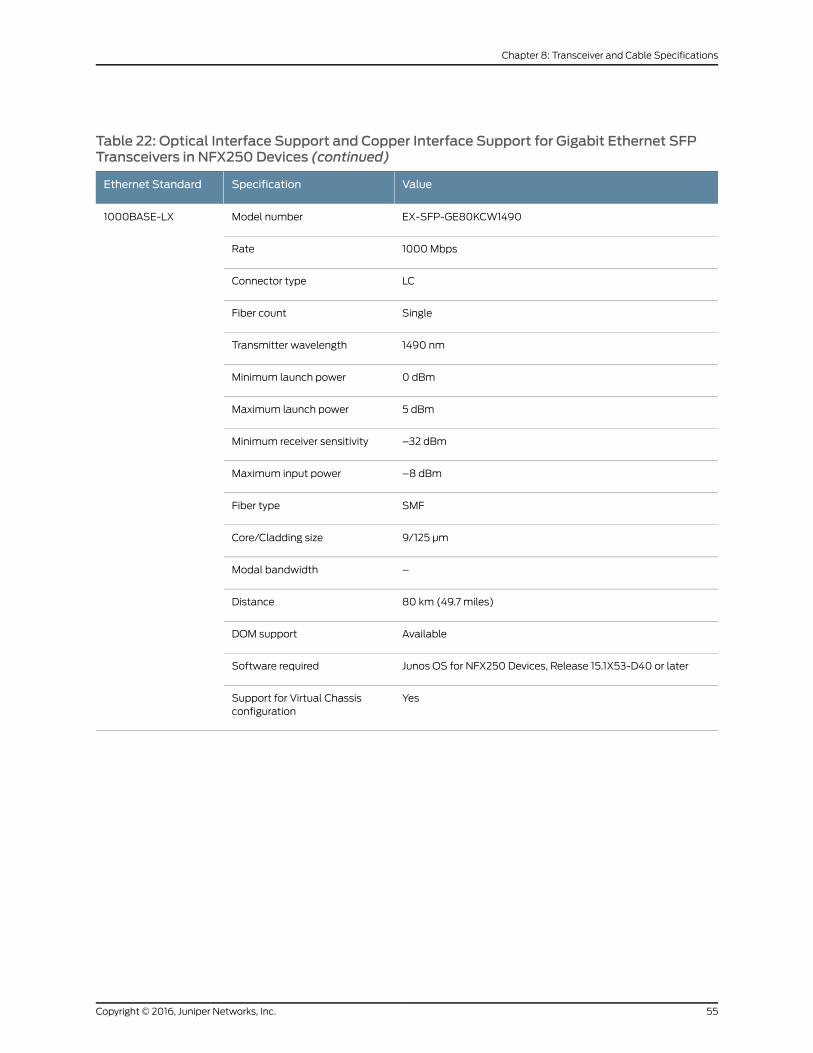
Table 22: Optical Interface Support and Copper Interface Support for Gigabit Ethernet SFPTransceivers in NFX250 Devices (continued)
ValueSpecificationEthernet Standard
EX-SFP-GE80KCW1490Model number1000BASE-LX
1000MbpsRate
LCConnector type
SingleFiber count
1490 nmTransmitter wavelength
0 dBmMinimum launch power
5 dBmMaximum launch power
–32 dBmMinimum receiver sensitivity
–8 dBmMaximum input power
SMFFiber type
9/125 µmCore/Cladding size
–Modal bandwidth
80 km (49.7 miles)Distance
AvailableDOM support
Junos OS for NFX250 Devices, Release 15.1X53-D40 or laterSoftware required
YesSupport for Virtual Chassisconfiguration
55Copyright © 2016, Juniper Networks, Inc.
Chapter 8: Transceiver and Cable Specifications

Table 22: Optical Interface Support and Copper Interface Support for Gigabit Ethernet SFPTransceivers in NFX250 Devices (continued)
ValueSpecificationEthernet Standard
EX-SFP-GE80KCW1510Model number1000BASE-LX
1000MbpsRate
LCConnector type
SingleFiber count
1510 nmTransmitter wavelength
0 dBmMinimum launch power
5 dBmMaximum launch power
–32 dBmMinimum receiver sensitivity
–8 dBmMaximum input power
SMFFiber type
9/125 µmCore/Cladding size
–Modal bandwidth
80 km (49.7 miles)Distance
AvailableDOM support
Junos OS for NFX250 Devices, Release 15.1X53-D40 or laterSoftware required
YesSupport for Virtual Chassisconfiguration
Copyright © 2016, Juniper Networks, Inc.56
NFX250 Network Services Platform Hardware Guide

Table 22: Optical Interface Support and Copper Interface Support for Gigabit Ethernet SFPTransceivers in NFX250 Devices (continued)
ValueSpecificationEthernet Standard
EX-SFP-GE80KCW1530Model number1000BASE-LX
1000MbpsRate
LCConnector type
SingleFiber count
1530 nmTransmitter wavelength
0 dBmMinimum launch power
5 dBmMaximum launch power
–32 dBmMinimum receiver sensitivity
–8 dBmMaximum input power
SMFFiber type
9/125 µmCore/Cladding size
–Modal bandwidth
80 km (49.7 miles)Distance
AvailableDOM support
Junos OS for NFX250 Devices, Release 15.1X53-D40 or laterSoftware required
YesSupport for Virtual Chassisconfiguration
57Copyright © 2016, Juniper Networks, Inc.
Chapter 8: Transceiver and Cable Specifications
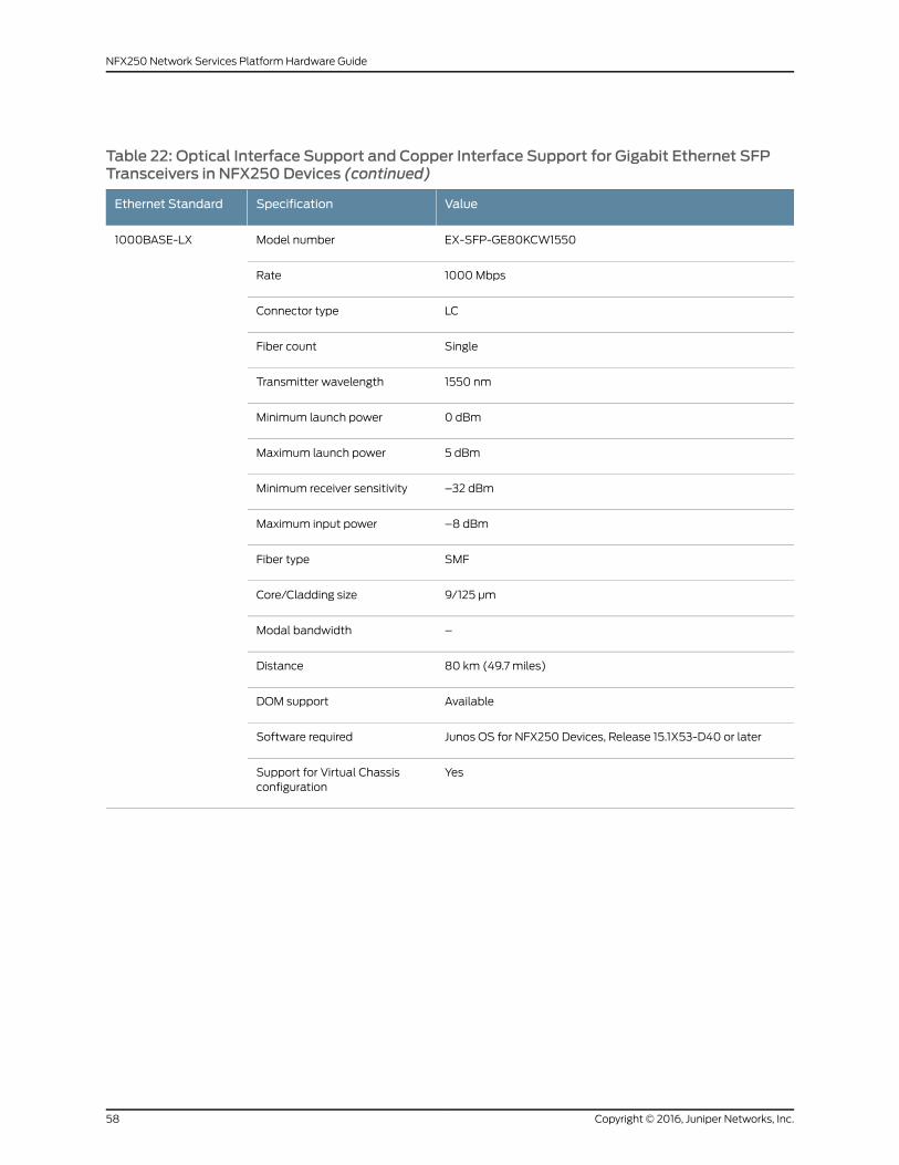
Table 22: Optical Interface Support and Copper Interface Support for Gigabit Ethernet SFPTransceivers in NFX250 Devices (continued)
ValueSpecificationEthernet Standard
EX-SFP-GE80KCW1550Model number1000BASE-LX
1000MbpsRate
LCConnector type
SingleFiber count
1550 nmTransmitter wavelength
0 dBmMinimum launch power
5 dBmMaximum launch power
–32 dBmMinimum receiver sensitivity
–8 dBmMaximum input power
SMFFiber type
9/125 µmCore/Cladding size
–Modal bandwidth
80 km (49.7 miles)Distance
AvailableDOM support
Junos OS for NFX250 Devices, Release 15.1X53-D40 or laterSoftware required
YesSupport for Virtual Chassisconfiguration
Copyright © 2016, Juniper Networks, Inc.58
NFX250 Network Services Platform Hardware Guide

Table 22: Optical Interface Support and Copper Interface Support for Gigabit Ethernet SFPTransceivers in NFX250 Devices (continued)
ValueSpecificationEthernet Standard
EX-SFP-GE80KCW1570Model number1000BASE-LX
1000MbpsRate
LCConnector type
SingleFiber count
1570 nmTransmitter wavelength
0 dBmMinimum launch power
5 dBmMaximum launch power
–32 dBmMinimum receiver sensitivity
–8 dBmMaximum input power
SMFFiber type
9/125 µmCore/Cladding size
–Modal bandwidth
80 km (49.7 miles)Distance
AvailableDOM support
Junos OS for NFX250 Devices, Release 15.1X53-D40 or laterSoftware required
YesSupport for Virtual Chassisconfiguration
59Copyright © 2016, Juniper Networks, Inc.
Chapter 8: Transceiver and Cable Specifications

Table 22: Optical Interface Support and Copper Interface Support for Gigabit Ethernet SFPTransceivers in NFX250 Devices (continued)
ValueSpecificationEthernet Standard
EX-SFP-GE80KCW1590Model number1000BASE-LX
1000MbpsRate
LCConnector type
SingleFiber count
1590 nmTransmitter wavelength
0 dBmMinimum launch power
5 dBmMaximum launch power
–32 dBmMinimum receiver sensitivity
–8 dBmMaximum input power
SMFFiber type
9/125 µmCore/Cladding size
–Modal bandwidth
80 km (49.7 miles)Distance
AvailableDOM support
Junos OS for NFX250 Devices, Release 15.1X53-D40 or laterSoftware required
YesSupport for Virtual Chassisconfiguration
Copyright © 2016, Juniper Networks, Inc.60
NFX250 Network Services Platform Hardware Guide

Table 22: Optical Interface Support and Copper Interface Support for Gigabit Ethernet SFPTransceivers in NFX250 Devices (continued)
ValueSpecificationEthernet Standard
EX-SFP-GE80KCW1610Model number1000BASE-LX
1000MbpsRate
LCConnector type
SingleFiber count
1610 nmTransmitter wavelength
0 dBmMinimum launch power
5 dBmMaximum launch power
–32 dBmMinimum receiver sensitivity
–8 dBmMaximum input power
SMFFiber type
9/125 µmCore/Cladding size
–Modal bandwidth
80 km (49.7 miles)Distance
AvailableDOM support
Junos OS for NFX250 Devices, Release 15.1X53-D40 or laterSoftware required
YesSupport for Virtual Chassisconfiguration
61Copyright © 2016, Juniper Networks, Inc.
Chapter 8: Transceiver and Cable Specifications

Table 23: Optical Interface Support for Gigabit Ethernet SFP+ Transceivers in NFX250Devices
ValueSpecificationEthernet Standard
EX-SFP-10GE-USRModel number10GBASE-USR
10 GbpsRate
LCConnector type
DualFiber count
850 nmTransmitter wavelength
–7.3 dBmMinimum launch power
–1.3 dBmMaximum launch power
–11.1 dBmMinimum receiver sensitivity
–1.0 dBmMaximum input power
MMFFiber type
50/125 µm50/125µm62.5/125µmCore/Cladding size
OM3OM3OM1Fiber grade
1500MHz/km500MHz/km200MHz/kmModal bandwidth
100m (328 ft)30m(98.4 ft)
10 m(32.8 ft)
Distance
AvailableDOM support
Junos OS for NFX250 Devices, Release 15.1X53-D40 or laterSoftware required
YesSupport for Virtual Chassisconfiguration
Copyright © 2016, Juniper Networks, Inc.62
NFX250 Network Services Platform Hardware Guide

Table 23: Optical Interface Support for Gigabit Ethernet SFP+ Transceivers in NFX250Devices (continued)
ValueSpecificationEthernet Standard
EX-SFP-10GE-SRModel number10GBASE-SR
10 GbpsRate
LCConnector type
DualFiber count
850 nmTransmitter wavelength
–7.3 dBmMinimum launch power
–1 dBmMaximum launch power
–9.9 dBmMinimum receiver sensitivity
–1 dBmMaximum input power
MMFFiber type
50/125µm50/125µm50/125µm62.5/125µm62.5/125µmCore/Cladding size
OM3OM2–OM1FDDIFiber grade
1500MHz/km500MHz/km400MHz/km200MHz/km160MHz/kmModal bandwidth
300m(984 ft)
82m(269 ft)
66m(216 ft)
33 m(108 ft)
26m(85 ft)
Distance
AvailableDOM support
Junos OS for NFX250 Devices, Release 15.1X53-D40 or laterSoftware required
YesSupport for Virtual Chassisconfiguration
63Copyright © 2016, Juniper Networks, Inc.
Chapter 8: Transceiver and Cable Specifications

Table 23: Optical Interface Support for Gigabit Ethernet SFP+ Transceivers in NFX250Devices (continued)
ValueSpecificationEthernet Standard
EX-SFP-10GE-LRModel number10GBASE-LR
10 GbpsRate
LCConnector type
DualFiber count
1310 nmTransmitter wavelength
–8.2 dBmMinimum launch power
0.5 dBmMaximum launch power
–18 dBmMinimum receiver sensitivity
0.5 dBmMaximum input power
SMFFiber type
9/125 µmCore/Cladding size
–Modal bandwidth
10 km (6.2 miles)Distance
AvailableDOM support
Junos OS for NFX250 Devices, Release 15.1X53-D40 or laterSoftware required
YesSupport for Virtual Chassisconfiguration
Copyright © 2016, Juniper Networks, Inc.64
NFX250 Network Services Platform Hardware Guide
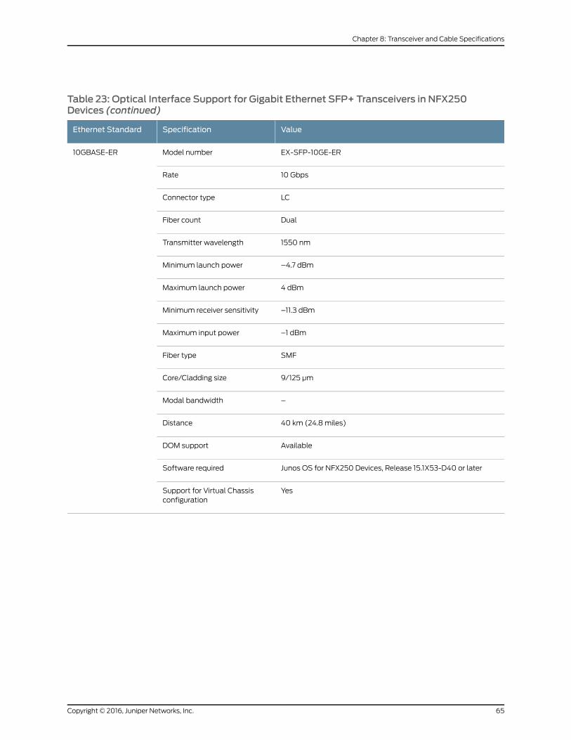
Table 23: Optical Interface Support for Gigabit Ethernet SFP+ Transceivers in NFX250Devices (continued)
ValueSpecificationEthernet Standard
EX-SFP-10GE-ERModel number10GBASE-ER
10 GbpsRate
LCConnector type
DualFiber count
1550 nmTransmitter wavelength
–4.7 dBmMinimum launch power
4 dBmMaximum launch power
–11.3 dBmMinimum receiver sensitivity
–1 dBmMaximum input power
SMFFiber type
9/125 µmCore/Cladding size
–Modal bandwidth
40 km (24.8 miles)Distance
AvailableDOM support
Junos OS for NFX250 Devices, Release 15.1X53-D40 or laterSoftware required
YesSupport for Virtual Chassisconfiguration
65Copyright © 2016, Juniper Networks, Inc.
Chapter 8: Transceiver and Cable Specifications

Table 23: Optical Interface Support for Gigabit Ethernet SFP+ Transceivers in NFX250Devices (continued)
ValueSpecificationEthernet Standard
EX-SFP-10GE-ZRModel number10GBASE-ZR
10 GbpsRate
LCConnector type
DualFiber count
1550 nmTransmitter wavelength
0 dBmMinimum launch power
5 dBmMaximum launch power
–20 dBmMinimum receiver sensitivity
–8 dBmMaximum input power
SMFFiber type
9/125 µmCore/Cladding size
–Modal bandwidth
80 km (49.7 miles)Distance
AvailableDOM support
Junos OS for NFX250 Devices, Release 15.1X53-D40 or laterSoftware required
YesSupport for Virtual Chassisconfiguration
RelatedDocumentation
Front Panel of an NFX250 Device on page 7•
• Installing a Transceiver in an NFX250 Device on page 109
• Removing a Transceiver from an NFX250 Device on page 110
SFP+ Direct Attach Cables for NFX250 Devices
Small form-factor pluggable plus transceiver (SFP+) direct attach copper (DAC) cables,
also known as Twinax cables, are suitable for in-rack connections between servers and
switches. They are suitable for short distances of up to 23 ft (7 m), making them ideal
Copyright © 2016, Juniper Networks, Inc.66
NFX250 Network Services Platform Hardware Guide
for highly cost-effective networking connectivity within a rack and between adjacent
racks.
This topic describes:
• Cable Specifications on page 67
• Standards Supported by These Cables on page 69
Cable Specifications
NFX250devices supportSFP+passiveDACcables. ThepassiveTwinaxcable is a straight
cable with no active electronic components. NFX250 devices support 1 m, 3 m, and 5m
long SFP+ passive DAC cables.
NOTE: We recommend that you use only SFP+ DAC cables purchased fromJuniper Networks with your Juniper Networks device.
CAUTION: If you face a problem running a Juniper Networks device that usesa third-partyopticor cable, the JuniperNetworksTechnicalAssistanceCenter(JTAC) can help you diagnose the source of the problem. Your JTAC engineermight recommendthatyoucheckthethird-partyopticorcableandpotentiallyreplace it with an equivalent Juniper Networks optic or cable that is qualifiedfor the device.
The cables are hot-removable and hot-insertable: You can remove and replace them
without powering off the switch or disrupting switch functions. A cable comprises a
low-voltage cable assembly that connects directly into two SFP+ ports, one at each end
of the cable. The cables use high-performance integrated duplex serial data links for
bidirectional communication and are designed for data rates of up to 10 Gbps.
Table 24 on page 68 describes the cable specifications.
67Copyright © 2016, Juniper Networks, Inc.
Chapter 8: Transceiver and Cable Specifications

Table 24: SFP+ Direct Attach Copper Cable Specifications
ValueSpecificationModel Number
10-Gbps full-duplex serial transmissionRateEX-SFP-10GE-DAC-1M
SFP+ passive Twinax cable assemblyConnector type
3.3 VSupply voltage
0.57WPower consumption (per end)
–40° C through 85° CStorage temperature
TwinaxCable type
30 AWGWire AWG
1 in. (2.54 cm)Minimum cable bend radius
100 ohmsCable characteristic impedance
2%maximumCrosstalk between pairs
1.31 nsec/ftTime delay
1 m (3.3 ft )Length
10-Gbps full-duplex serial transmissionRateEX-SFP-10GE-DAC-3M
SFP+ passive Twinax cable assemblyConnector type
3.3 VSupply voltage
0.57WPower consumption (per end)
–40° C through 85° CStorage temperature
TwinaxCable type
30 AWGWire AWG
1 in. (2.54 cm)Minimum cable bend radius
100 ohmsCable characteristic impedance
2%maximumCrosstalk between pairs
1.31 nsec/ftTime delay
3 m (9.9 ft)Length
Copyright © 2016, Juniper Networks, Inc.68
NFX250 Network Services Platform Hardware Guide

Table 24: SFP+ Direct Attach Copper Cable Specifications (continued)
ValueSpecificationModel Number
10-Gbps full-duplex serial transmissionRateEX-SFP-10GE-DAC-5M
SFP+ passive Twinax cable assemblyConnector type
3.3 VSupply voltage
0.57WPower consumption (per end)
–40° C through 85° CStorage temperature
TwinaxCable type
24 AWGWire AWG
1 in. (2.54 cm)Minimum cable bend radius
100 ohmsCable characteristic impedance
2%maximumCrosstalk between pairs
1.31 nsec/ftTime delay
5m (16.4 ft)Length
Standards Supported by These Cables
The cables comply with the following standards:
• SFPmechanical standard SFF-843—see ftp://ftp.seagate.com/sff/SFF-8431.PDF .
• Electrical interface standard SFF-8432—see ftp://ftp.seagate.com/sff/SFF-8432.PDF .
• SFP+Multi-Source Alliance (MSA) standards
RelatedDocumentation
Pluggable Transceivers Supported on NFX250 Devices on page 41•
• Installing a Transceiver in an NFX250 Device on page 109
• Removing a Transceiver from an NFX250 Device on page 110
CableSpecificationsforConsoleandManagementConnectionsfor theNFX250Devices
Table 25 on page 70 lists the specifications for the cables that connect the NFX250
devices to amanagement device.
69Copyright © 2016, Juniper Networks, Inc.
Chapter 8: Transceiver and Cable Specifications

Table 25: Cable Specifications for Console andManagement Connections for the NFX250Devices
DeviceReceptacleMaximum LengthCable SuppliedCable Specification
Port on NFX250Device
RJ-457 feet (2.13 meters)One 7-foot (2.13-meter) longRJ-45 patch cable and RJ-45 toDB-9 adapter
RS-232(EIA-232)serial cableConsole port
RJ-45328 feet(100meters)
One 7-foot (2.13-meter) longRJ-45 patch cable
Category 5 cable orequivalent suitable for1000BASE-T operation
Management port
RelatedDocumentation
Console Port Connector Pinouts for NFX250 Devices on page 36•
• Management Port Connector Pinout Information for an NFX250 Device on page 37
• Connecting an NFX250 Device to a Management Console on page 96
• Connecting anNFX250Device to aNetwork forOut-of-BandManagement onpage95
Understanding NFX250 Devices Fiber-Optic Cable Signal Loss, Attenuation, andDispersion
To determine the power budget and power margin needed for fiber-optic connections,
you need to understand how signal loss, attenuation, and dispersion affect transmission.
The NFX250 devices use various types of network cable, including multimode and
single-mode fiber-optic cables.
• Signal Loss in Multimode and Single-Mode Fiber-Optic Cables on page 70
• Attenuation and Dispersion in Fiber-Optic Cable on page 71
Signal Loss in Multimode and Single-Mode Fiber-Optic Cables
Multimode fiber is large enough in diameter to allow rays of light to reflect internally
(bounce off the walls of the fiber). Interfaces with multimode optics typically use LEDs
as light sources. However, LEDs are not coherent light sources. They spray varying
wavelengths of light into themultimode fiber, which reflects the light at different angles.
Light rays travel in jagged lines through amultimode fiber, causing signal dispersion.
When light traveling in the fiber core radiates into the fiber cladding (layers of lower
refractive indexmaterial in close contact with a core material of higher refractive index),
higher-ordermode loss occurs. Together, these factors reduce the transmission distance
of multimode fiber compared to that of single-mode fiber.
Single-mode fiber is so small in diameter that rays of light reflect internally through one
layer only. Interfaceswith single-mode optics use lasers as light sources. Lasers generate
a singlewavelength of light, which travels in a straight line through the single-mode fiber.
Compared to multimode fiber, single-mode fiber has a higher bandwidth and can carry
signals for longer distances. It is consequently more expensive.
Copyright © 2016, Juniper Networks, Inc.70
NFX250 Network Services Platform Hardware Guide

For information about the maximum transmission distance and supported wavelength
range for the types of single-mode andmultimode fiber-optic cables that are connected
to the NFX250 devices, see “Pluggable Transceivers Supported on NFX250 Devices” on
page 41. Exceeding the maximum transmission distances can result in significant signal
loss, which causes unreliable transmission.
Attenuation and Dispersion in Fiber-Optic Cable
Anoptical data link functionscorrectlyprovided thatmodulated light reaching the receiver
has enough power to be demodulated correctly. Attenuation is the reduction in strength
of the light signal during transmission. Passivemedia components such as cables, cable
splices, and connectors cause attenuation. Although attenuation is significantly lower
for optical fiber than for other media, it still occurs in both multimode and single-mode
transmission. An efficient optical data link must transmit enough light to overcome
attenuation.
Dispersion is the spreading of the signal over time. The following two types of dispersion
can affect signal transmission through an optical data link:
• Chromatic dispersion, which is the spreading of the signal over time caused by the
different speeds of light rays.
• Modal dispersion,which is the spreading of the signal over time causedby thedifferent
propagation modes in the fiber.
For multimode transmission, modal dispersion, rather than chromatic dispersion or
attenuation, usually limits the maximum bit rate and link length. For single-mode
transmission,modaldispersion is nota factor.However, at higherbit ratesandover longer
distances, chromatic dispersion limits the maximum link length.
An efficient optical data linkmust have enough light to exceed theminimum power that
the receiver requires to operate within its specifications. In addition, the total dispersion
mustbewithin the limits specified for the typeof link inTelcordiaTechnologiesdocument
GR-253-CORE (Section 4.3) and International Telecommunications Union (ITU)
document G.957.
When chromatic dispersion is at the maximum allowed, its effect can be considered as
a power penalty in the power budget. The optical power budget must allow for the sum
of component attenuation, power penalties (including those from dispersion), and a
safety margin for unexpected losses.
RelatedDocumentation
Calculating the Fiber-Optic Cable Power Budget for an NFX250 Device on page 71•
• Calculating the Fiber-Optic Cable Power Margin for an NFX250 Device on page 72
Calculating the Fiber-Optic Cable Power Budget for an NFX250 Device
Calculate the link's power budget when planning fiber-optic cable layout and distances
to ensure that fiber-optic connections have sufficient power for correct operation. The
powerbudget is themaximumamountofpower the linkcan transmit.Whenyoucalculate
71Copyright © 2016, Juniper Networks, Inc.
Chapter 8: Transceiver and Cable Specifications
thepowerbudget, youuseaworst-caseanalysis toprovideamarginof error, even though
all the parts of an actual system do not operate at the worst-case levels.
To calculate the worst-case estimate for fiber-optic cable power budget (PB) for the
link:
1. Determinevalues for the link'sminimumtransmitterpower (PT)andminimumreceiver
sensitivity (PR). For example, here, (P
T)and(P
R)aremeasured indecibels, anddecibels
are referenced to 1 milliwatt (dBm).
PT= –15 dBm
PR= –28 dBm
NOTE: See the specifications for your transmitter and receiver to find theminimum transmitter power andminimum receiver sensitivity.
2. Calculate the power budget (PB) by subtracting (PR) from (PT):
–15 dBm – (–28 dBm) = 13 dBm
RelatedDocumentation
Understanding NFX250 Devices Fiber-Optic Cable Signal Loss, Attenuation, and
Dispersion on page 70
•
• Calculating the Fiber-Optic Cable Power Margin for an NFX250 Device on page 72
Calculating the Fiber-Optic Cable Power Margin for an NFX250 Device
Calculate the link's power margin when planning fiber-optic cable layout and distances
to ensure that fiber-optic connections have sufficient signal power to overcome system
losses and still satisfy the minimum input requirements of the receiver for the required
performance level. The power margin (PM) is the amount of power available after
attenuation or link loss (LL) has been subtracted from the power budget (PB).
When you calculate the powermargin, you use aworst-case analysis to provide amargin
of error, even though all the parts of an actual system do not operate at worst-case
levels. Apowermargin (PM) greater than zero indicates that thepowerbudget is sufficient
to operate the receiver and that it does not exceed themaximum receiver input power.
This means the link will work. A (PM) that is zero or negative indicates insufficient power
to operate the receiver. See the specification for your receiver to find the maximum
receiver input power.
Before you begin to calculate the power margin:
Copyright © 2016, Juniper Networks, Inc.72
NFX250 Network Services Platform Hardware Guide

• Calculate the power budget. See “Calculating the Fiber-Optic Cable Power Budget for
an NFX250 Device” on page 71.
To calculate the worst-case estimate for the power margin (PM) for the link:
1. Determine the maximum value for link loss (LL) by adding estimated values for
applicable link-loss factors—for example, use the sample values for various factors
as provided in Table 26 on page 73 (here, the link is 2 km long andmultimode, and
the (PB) is 13 dBm):
Table 26: Estimated Values for Factors Causing Link Loss
Sample Link Loss (LL) Calculation ValuesEstimated Link-Loss ValueLink-Loss Factor
0.5 dBmMultimode—0.5 dBmHigher-ordermodelosses
0 dBmSingle-mode—None
0 dBmMultimode—None, if product ofbandwidth and distance is lessthan 500MHz/km
Modal and chromaticdispersion
0 dBmSingle-mode—None
This example assumes five connectors. Loss for fiveconnectors: 5 (0.5 dBm) = 2.5 dBm.
0.5 dBmConnector
This exampleassumes twosplices. Loss for twosplices:2 (0.5 dBm) = 1 dBm.
0.5 dBmSplice
This example assumes the link is 2 km long. Fiberattenuation for 2 km: 2 km (1 dBm/km) = 2 dBm.
Multimode—1 dBm/kmFiber attenuation
This example assumes the link is 2 km long. Fiberattenuation for 2 km: 2 km (0.5 dBm/km) = 1 dBm.
Single-mode—0.5 dBm/km
1 dBm1 dBmClock Recovery Module(CRM)
NOTE: For information about the actual amount of signal loss caused byequipment and other factors, see your vendor documentation for thatequipment.
2. Calculate the (PM) by subtracting (LL) from (P
B):
PB– LL = P
M
13 dBm – 0.5 dBm [HOL] – 5 (0.5 dBm) – 2 (0.5 dBm) – 2 km (1.0 dBm/km) – 1 dB
[CRM] = PM
13 dBm – 0.5 dBm – 2.5 dBm – 1 dBm – 2 dBm – 1 dBm = PM
73Copyright © 2016, Juniper Networks, Inc.
Chapter 8: Transceiver and Cable Specifications
PM= 6 dBm
Thecalculatedpowermargin is greater than zero, indicating that the link has sufficient
power for transmission. Also, the power margin value does not exceed themaximum
receiver input power. Refer to the specifications for your receiver to find themaximum
receiver input power.
RelatedDocumentation
• Understanding NFX250 Devices Fiber-Optic Cable Signal Loss, Attenuation, and
Dispersion on page 70
• Calculating the Fiber-Optic Cable Power Budget for an NFX250 Device on page 71
Copyright © 2016, Juniper Networks, Inc.74
NFX250 Network Services Platform Hardware Guide

PART 3
Initial Installation and Configuration
• Unpacking the Network Services Platform on page 77
• Installing the Network Services Platform on page 81
• Connecting the Network Services Platform to Power on page 91
• Connecting the Network Services Platform to the Network on page 95
• Initially Configuring the Network Services Platform on page 99
75Copyright © 2016, Juniper Networks, Inc.

Copyright © 2016, Juniper Networks, Inc.76
NFX250 Network Services Platform Hardware Guide

CHAPTER 9
Unpacking theNetworkServicesPlatform
• Unpacking an NFX250 Device on page 77
• Parts Inventory (Packing List) for an NFX250 Device on page 77
• Registering Products—Mandatory for Validating SLAs on page 78
Unpacking an NFX250 Device
The NFX250 devices are shipped in a cardboard carton, secured with foam packing
material. The carton has an accessory compartment and contains the quick start
instructions.
CAUTION: NFX250 devices aremaximally protected inside the shippingcarton. Do not unpack the switches until you are ready to begin installation.
To unpack the switch:
1. Open the carton.
2. Pull out the packing material holding the device in place.
3. Verify the parts received against the inventory on the label attached to the carton.
See “Parts Inventory (Packing List) for an NFX250 Device” on page 77.
4. Save the shipping carton and packing materials in case you need to move or ship the
switch later.
RelatedDocumentation
Configuring an NFX250 Device on page 99•
Parts Inventory (Packing List) for an NFX250 Device
The NFX250 devices are shipped in a cardboard carton, secured with foam packing
material. The carton contains an accessory box.
The device shipment includes a packing list. Check the parts you receive in the device
shipping carton against the items on the packing list. The parts shipped depend on the
configuration you order.
77Copyright © 2016, Juniper Networks, Inc.
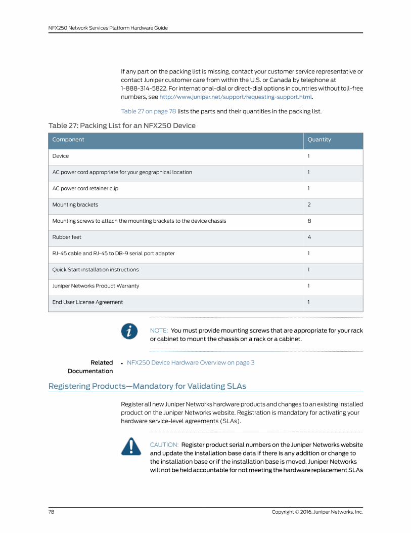
If any part on the packing list is missing, contact your customer service representative or
contact Juniper customer care fromwithin the U.S. or Canada by telephone at
1-888-314-5822. For international-dial or direct-dial options in countrieswithout toll-free
numbers, see http://www.juniper.net/support/requesting-support.html.
Table 27 on page 78 lists the parts and their quantities in the packing list.
Table 27: Packing List for an NFX250 Device
QuantityComponent
1Device
1AC power cord appropriate for your geographical location
1AC power cord retainer clip
2Mounting brackets
8Mounting screws to attach themounting brackets to the device chassis
4Rubber feet
1RJ-45 cable and RJ-45 to DB-9 serial port adapter
1Quick Start installation instructions
1Juniper Networks ProductWarranty
1End User License Agreement
NOTE: Youmust providemounting screws that are appropriate for your rackor cabinet tomount the chassis on a rack or a cabinet.
RelatedDocumentation
NFX250 Device Hardware Overview on page 3•
Registering Products—Mandatory for Validating SLAs
Register all new JuniperNetworkshardwareproductsandchanges toanexisting installed
product on the Juniper Networks website. Registration is mandatory for activating your
hardware service-level agreements (SLAs).
CAUTION: Register product serial numbers on the Juniper Networkswebsiteand update the installation base data if there is any addition or change tothe installation base or if the installation base is moved. Juniper Networkswill notbeheldaccountable fornotmeeting thehardware replacementSLAs
Copyright © 2016, Juniper Networks, Inc.78
NFX250 Network Services Platform Hardware Guide

forproducts thatdonothave registeredserialnumbersoraccurate installationbase data.
Register your products at: https://tools.juniper.net/svcreg/SRegSerialNum.jsp.
Update your installation base at: If you have a Juniper J-Care service contract, register
any addition, change, or upgrade of hardware components at
https://www.juniper.net/customers/support/tools/updateinstallbase/. Failure to do so
can result in significant delays if you need replacement parts. This note does not apply
if you replace existing components with the same type of component.
RelatedDocumentation
• Contacting Customer Support to Obtain Return Material Authorization
• ContactingCustomerSupport toObtainaReturnMaterialsAuthorization foranNFX250
Device on page 120
79Copyright © 2016, Juniper Networks, Inc.
Chapter 9: Unpacking the Network Services Platform

Copyright © 2016, Juniper Networks, Inc.80
NFX250 Network Services Platform Hardware Guide

CHAPTER 10
Installing the Network Services Platform
• Installing and Connecting an NFX250 Device on page 81
• Mounting an NFX250 Device on page 82
• Mounting an NFX250 Device on a Desk or Other Level Surface on page 82
• Mounting an NFX250-LS1 Device on aWall on page 83
• Mounting an NFX250 Device on Two Posts in a Rack on page 86
• Mounting an NFX250 Device on Four Posts in a Rack or Cabinet on page 88
Installing and Connecting an NFX250 Device
To install and connect an NFX250 device:
1. Follow instructions in “Unpacking an NFX250 Device” on page 77.
2. Mount the device by following instructions appropriate for your site:
• “Mounting an NFX250 Device on a Desk or Other Level Surface” on page 82 (using
the rubber feet provided)
• “Mounting an NFX250 Device on Two Posts in a Rack” on page 86 (using the
mounting brackets provided)
• “Mounting anNFX250Device on Four Posts in aRack or Cabinet” on page88 (using
the separately orderable four-post rack-mount kit)
• “Mounting an NFX250-LS1 Device on aWall” on page 83 ( using the separately
orderable wall-mount kit)
3. Follow instructions in “Connecting Earth Ground to an NFX250 Device” on page 91.
4. Follow instructions in “Connecting AC Power to an NFX250 Device” on page 92.
5. Perform initial configuration of the device by following instructions in “Configuring an
NFX250 Device” on page 99.
6. Set the device’s management options by following the appropriate instructions:
• Connecting an NFX250 Device to a Management Console on page 96
• Connecting an NFX250 Device to a Network for Out-of-Band Management on
page 95
81Copyright © 2016, Juniper Networks, Inc.
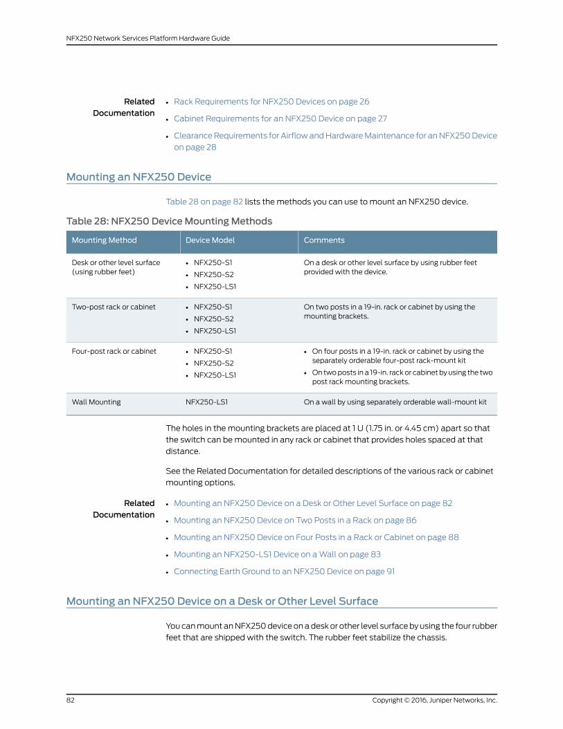
RelatedDocumentation
Rack Requirements for NFX250 Devices on page 26•
• Cabinet Requirements for an NFX250 Device on page 27
• ClearanceRequirements for AirflowandHardwareMaintenance for anNFX250Device
on page 28
Mounting an NFX250 Device
Table 28 on page 82 lists the methods you can use to mount an NFX250 device.
Table 28: NFX250 DeviceMountingMethods
CommentsDevice ModelMounting Method
On a desk or other level surface by using rubber feetprovided with the device.
• NFX250-S1
• NFX250-S2
• NFX250-LS1
Desk or other level surface(using rubber feet)
On two posts in a 19-in. rack or cabinet by using themounting brackets.
• NFX250-S1
• NFX250-S2
• NFX250-LS1
Two-post rack or cabinet
• On four posts in a 19-in. rack or cabinet by using theseparately orderable four-post rack-mount kit
• Ontwoposts in a 19-in. rackor cabinet byusing the twopost rack mounting brackets.
• NFX250-S1
• NFX250-S2
• NFX250-LS1
Four-post rack or cabinet
On a wall by using separately orderable wall-mount kitNFX250-LS1Wall Mounting
The holes in the mounting brackets are placed at 1 U (1.75 in. or 4.45 cm) apart so that
the switch can bemounted in any rack or cabinet that provides holes spaced at that
distance.
See the Related Documentation for detailed descriptions of the various rack or cabinet
mounting options.
RelatedDocumentation
Mounting an NFX250 Device on a Desk or Other Level Surface on page 82•
• Mounting an NFX250 Device on Two Posts in a Rack on page 86
• Mounting an NFX250 Device on Four Posts in a Rack or Cabinet on page 88
• Mounting an NFX250-LS1 Device on aWall on page 83
• Connecting Earth Ground to an NFX250 Device on page 91
Mounting an NFX250 Device on a Desk or Other Level Surface
YoucanmountanNFX250deviceonadeskor other level surfacebyusing the four rubber
feet that are shipped with the switch. The rubber feet stabilize the chassis.
Copyright © 2016, Juniper Networks, Inc.82
NFX250 Network Services Platform Hardware Guide

Before mounting the device on a desk or other level surface:
• Verify that the site meets the requirements described in “Site Preparation Checklist
for NFX250 Devices” on page 21.
• Place the desk in its permanent location, allowing adequate clearance for airflow and
maintenance, and secure it to the building structure.
• Read “General Safety Guidelines andWarnings” on page 129, with particular attention
to “Chassis Lifting Guidelines for NFX250 Devices” on page 138.
• Ensure that you have the 4 rubber feet to stabilize the chassis on the a desk or other
level surface (provided in the accessory box in the switch carton)
Tomount an NFX250 device on a desk or other level surface:
1. Remove the device from the shipping carton (see “Unpacking an NFX250 Device” on
page 77).
2. Turn the chassis upside down on the desk or the level surface where you intend to
mount the device.
3. Attach the rubber feet to the bottom of the chassis as shown in Figure 11 on page 83
4. Turn the chassis right side up on the desk or the level surface.
Figure 11: Attaching Rubber Feet to the NFX250 Device
RelatedDocumentation
Connecting Earth Ground to an NFX250 Device on page 91•
• Connecting AC Power to an NFX250 Device on page 92
• ClearanceRequirements for AirflowandHardwareMaintenance for anNFX250Device
on page 28
Mounting an NFX250-LS1 Device on aWall
You canmount an NFX250-LS1 device on a wall by using the separately orderable
wall-mount kit.
Before mounting an NFX250-LS1 device on a wall:
• Verify that the site meets the requirements described in “Site Preparation Checklist
for NFX250 Devices” on page 21.
• Read “General Safety Guidelines andWarnings” on page 129, with particular attention
to “Chassis Lifting Guidelines for NFX250 Devices” on page 138.
83Copyright © 2016, Juniper Networks, Inc.
Chapter 10: Installing the Network Services Platform
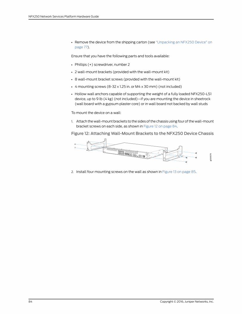
• Remove the device from the shipping carton (see “Unpacking an NFX250 Device” on
page 77).
Ensure that you have the following parts and tools available:
• Phillips (+) screwdriver, number 2
• 2 wall-mount brackets (provided with the wall-mount kit)
• 8wall-mount bracket screws (provided with the wall-mount kit)
• 4mounting screws (8-32 x 1.25 in. or M4 x 30mm) (not included)
• Hollowwall anchors capable of supporting the weight of a fully loaded NFX250-LS1
device, up to 9 lb (4 kg) (not included)—if you are mounting the device in sheetrock
(wall board with a gypsum plaster core) or in wall board not backed by wall studs
Tomount the device on a wall:
1. Attach thewall-mountbrackets to thesidesof thechassisusing fourof thewall-mount
bracket screws on each side, as shown in Figure 12 on page 84.
Figure 12: AttachingWall-Mount Brackets to the NFX250 Device Chassis
2. Install four mounting screws on the wall as shown in Figure 13 on page 85.
Copyright © 2016, Juniper Networks, Inc.84
NFX250 Network Services Platform Hardware Guide

Figure 13: Measurements for Installing Mounting Screws for NFX250Device on aWall
a. Drill a hole A and install a mounting screw.
b. Drill a hole B at a distance of 5.98 in. (15.19 cm.) on a level line to the right from
hole A and install a mounting screw.
c. Drill two holes at a distance of 18.66 in. (47.39 cm) on a plumb line from hole A
and B, install the mounting screws.
d. Screw themounting screws only part way in, leaving about 1/4 in. (6mm)distance
between the head of the screw and the wall.
3. If themounting screws are inserted in wall boardwith no stud behind it, youmust use
dry wall anchors rated to support 20 lb (9 kg). Insert the screws into wall studs
wherever possible to provide added support for the chassis.
4. Graspeachsideof thedevice, lift thedevice, andhang thebrackets fromthemounting
screws such that the front panel of the device faces to your right or left side as shown
in Figure 14 on page 86.
85Copyright © 2016, Juniper Networks, Inc.
Chapter 10: Installing the Network Services Platform
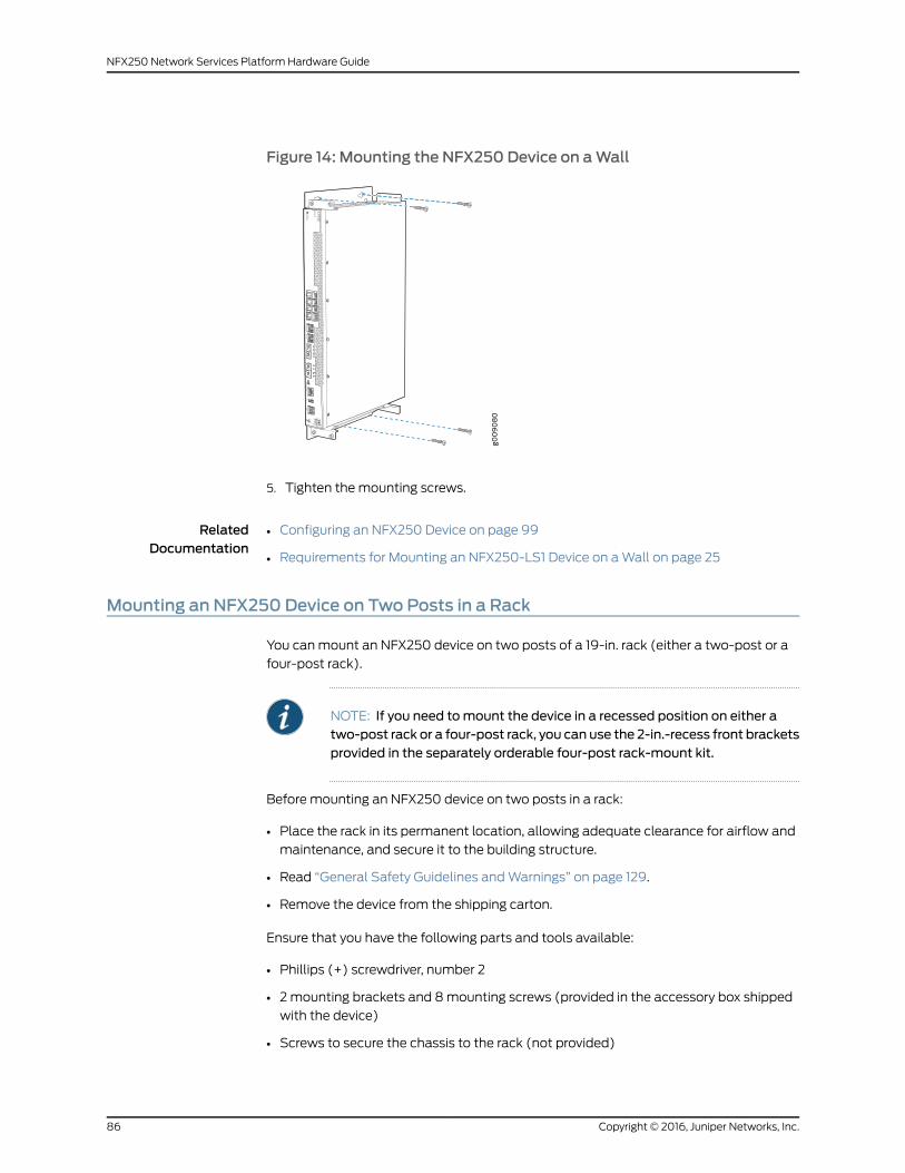
Figure 14: Mounting the NFX250 Device on aWall
5. Tighten themounting screws.
RelatedDocumentation
Configuring an NFX250 Device on page 99•
• Requirements for Mounting an NFX250-LS1 Device on aWall on page 25
Mounting an NFX250 Device on Two Posts in a Rack
You canmount an NFX250 device on two posts of a 19-in. rack (either a two-post or a
four-post rack).
NOTE: If you need tomount the device in a recessed position on either atwo-post rack or a four-post rack, you can use the 2-in.-recess front bracketsprovided in the separately orderable four-post rack-mount kit.
Before mounting an NFX250 device on two posts in a rack:
• Place the rack in its permanent location, allowing adequate clearance for airflow and
maintenance, and secure it to the building structure.
• Read “General Safety Guidelines andWarnings” on page 129.
• Remove the device from the shipping carton.
Ensure that you have the following parts and tools available:
• Phillips (+) screwdriver, number 2
• 2mounting brackets and 8mounting screws (provided in the accessory box shipped
with the device)
• Screws to secure the chassis to the rack (not provided)
Copyright © 2016, Juniper Networks, Inc.86
NFX250 Network Services Platform Hardware Guide
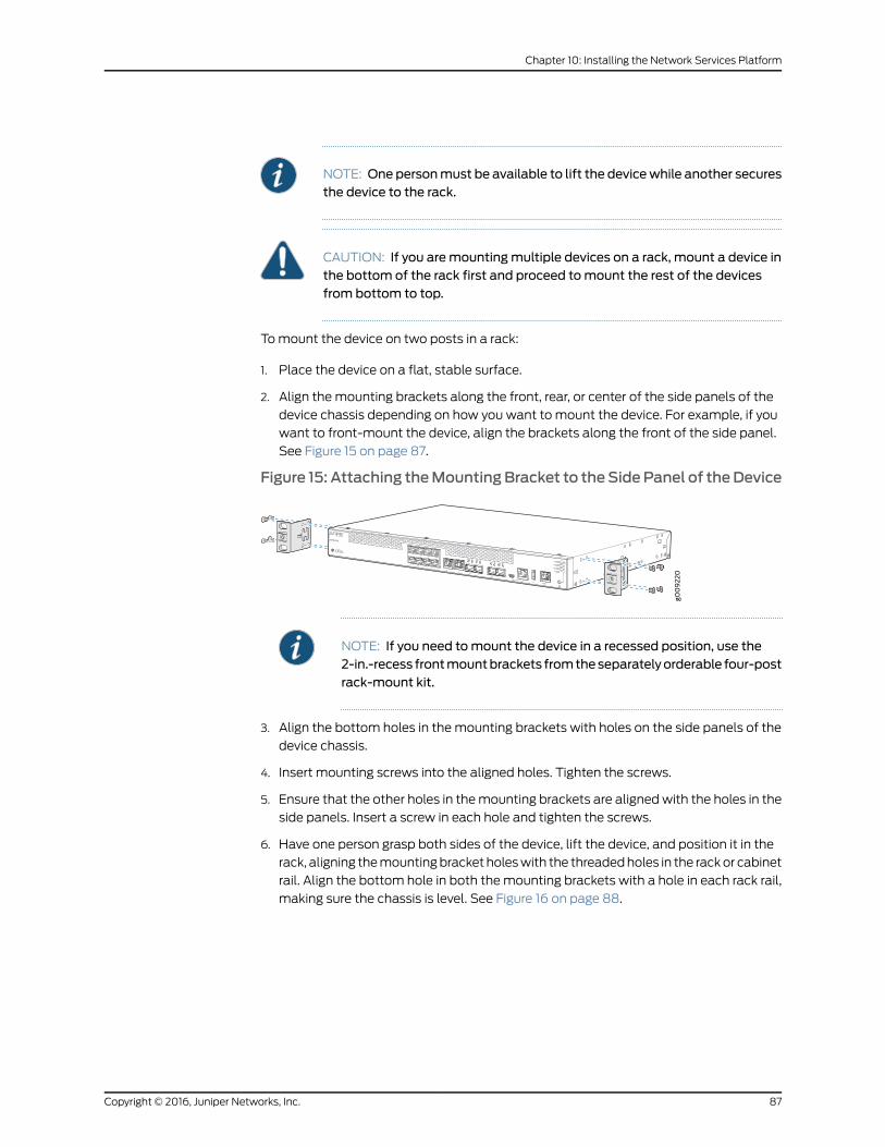
NOTE: One personmust be available to lift the devicewhile another securesthe device to the rack.
CAUTION: If you aremountingmultiple devices on a rack, mount a device inthe bottom of the rack first and proceed tomount the rest of the devicesfrom bottom to top.
Tomount the device on two posts in a rack:
1. Place the device on a flat, stable surface.
2. Align the mounting brackets along the front, rear, or center of the side panels of the
device chassis depending on how you want to mount the device. For example, if you
want to front-mount the device, align the brackets along the front of the side panel.
See Figure 15 on page 87.
Figure 15: Attaching theMountingBracket to theSidePanel of theDevice
NOTE: If you need tomount the device in a recessed position, use the2-in.-recess frontmountbrackets fromtheseparatelyorderable four-postrack-mount kit.
3. Align the bottom holes in the mounting brackets with holes on the side panels of the
device chassis.
4. Insert mounting screws into the aligned holes. Tighten the screws.
5. Ensure that the other holes in themounting brackets are alignedwith the holes in the
side panels. Insert a screw in each hole and tighten the screws.
6. Have one person grasp both sides of the device, lift the device, and position it in the
rack, aligning themountingbracket holeswith the threadedholes in the rackor cabinet
rail. Align the bottom hole in both themounting brackets with a hole in each rack rail,
making sure the chassis is level. See Figure 16 on page 88.
87Copyright © 2016, Juniper Networks, Inc.
Chapter 10: Installing the Network Services Platform

Figure 16: Mounting the Device on Two Posts in a Rack
7. Have a second person secure the device to the rack by using the appropriate screws.
Tighten the screws.
8. Ensure that the device chassis is level by verifying that all screws on one side of the
rack are aligned with the screws on the other side.
RelatedDocumentation
Connecting AC Power to an NFX250 Device on page 92•
• Connecting Earth Ground to an NFX250 Device on page 91
• Rack-Mounting and Cabinet-MountingWarnings on page 140
Mounting an NFX250 Device on Four Posts in a Rack or Cabinet
You canmount an NFX250 device on four posts of a 19-in. rack or cabinet by using the
separately orderable four-post rack-mount kit. (The remainder of this topic uses rack to
mean rack or cabinet.).
You canmount the device on two posts in either a two-post rack or a four-post rack by
using themounting brackets providedwith the device. See “Mounting anNFX250Device
on Two Posts in a Rack” on page 86.
NOTE: If you aremounting the device on four posts, ensure that the rack is21.5 in. through 31.5 in. deep if you will mount the device flush with the rackfront and that the rack is 23.5 in. through 32.5 in. deep if you will mount thedevice 2 in. recessed from the rack front, thus ensuring that the protectiveearthing terminal is accessible through the opening in the rearmounting-blade.
Before mounting the device on four posts in a rack:
Copyright © 2016, Juniper Networks, Inc.88
NFX250 Network Services Platform Hardware Guide
• Place the rack in its permanent location, allowing adequate clearance for airflow and
maintenance, and secure it to the building structure.
• Read “General Safety Guidelines andWarnings” on page 129, with particular attention
to “Chassis Lifting Guidelines for NFX250 Devices” on page 138.
• Remove the device from the shipping carton (see “Unpacking an NFX250 Device” on
page 77).
• Have two persons available to mount the device. One person will support the device
in a level position, and the second person will secure the device to the rack.
Ensure that you have the following parts and tools available:
• Phillips (+) screwdriver, number 2
• 12 flat-head M4x6-mmPhillips mounting screws (provided with the four-post
rack-mount kit)
• One pair of front-mounting brackets
• One pair of rear mounting-blades
• Screws to secure the front-mounting brackets and the rear mounting-blades to the
rack (not provided)
CAUTION: If you aremountingmultiple units on a rack, mount the heaviestunit at the bottom of the rack andmount the other units from the bottom ofthe rack to the top in decreasing order of the weight of the units.
Tomount the device on four posts in a rack:
1. Place the device on a flat, stable surface.
2. Align a front bracket (either flush with the front of the chassis or 2-in.-recessed from
the front of the chassis) along the sidepanel of thedevice chassis. Align the twoholes
in the front of the brackets with the two holes on the front of the side panel.
NOTE: Each side of the chassis has twelve holes for attaching thefront-mounting brackets to the device.
Six holes on the chassis side alignwith six holes in the front bracketwhenthe front bracket is mounted flush with the chassis front or recessed 2 in.from the front of the chassis.
3. Insert M4x6-mmPhillips flat-headmounting screws into the two aligned holes and
tighten the screws. Ensure that the remaining twoholes in the frontbracket arealigned
with the two holes in the side panel. See Figure 17 on page 90.
89Copyright © 2016, Juniper Networks, Inc.
Chapter 10: Installing the Network Services Platform

Figure 17: Attaching the Front-Mounting Bracket to the Device Chassis
g009
222
4. Insert M4x6-mmPhillips flat-headmounting screws into the remaining two holes in
the front bracket and tighten the screws.
5. Repeat steps2 through4 for attaching the frontbracket to theother sideof thechassis.
6. Have one person grasp both sides of the device, lift the device, and position it in the
rack, aligning the front bracket holes with the threaded holes in the front post of the
rack. Align the bottom hole in both the front-mounting brackets with a hole in each
rack rail, making sure the chassis is level. See Figure 18 on page 90.
Figure 18: Mounting the Device on the Front Posts in a Rack
7. Haveasecondpersonsecure the frontof thedevice to the rackbyusing theappropriate
screws for your rack.
8. Slide the rear mounting-blades into the front-mounting brackets.
9. Attach the rear mounting-blades to the rear post by using the appropriate screws for
your rack. Tighten the screws.
10. Ensure that the device chassis is level by verifying that all the screws on the front of
the rack are aligned with the screws at the back of the rack.
RelatedDocumentation
• Connecting Earth Ground to an NFX250 Device on page 91
• Connecting AC Power to an NFX250 Device on page 92
• Rack-Mounting and Cabinet-MountingWarnings on page 140
Copyright © 2016, Juniper Networks, Inc.90
NFX250 Network Services Platform Hardware Guide

CHAPTER 11
Connecting theNetworkServicesPlatformto Power
• Connecting Earth Ground to an NFX250 Device on page 91
• Connecting AC Power to an NFX250 Device on page 92
Connecting Earth Ground to an NFX250 Device
Earth grounding is recommended, but optional for the NFX250 device. The device
functions normally without earth grounding. Electromagnetic Compatibility (EMC) and
Electrostatic Discharge (ESD) requirements aremet by the device chassis. TheACpower
cord provides surge protection.
ToconnectNFX250device toearthground, youmustuse theprotectiveearthing terminal
on the device chassis. See Figure 19 on page 92.
This topic describes:
• Parts andToolsRequired forConnectinganNFX250Device toEarthGroundonpage91
• Connecting Earth Ground to an NFX250 Device on page 92
Parts and Tools Required for Connecting an NFX250 Device to Earth Ground
Table 29 on page 92 lists the earthing terminal location, grounding cable requirements,
grounding lug specifications, screws and washers required, and the screwdriver needed
for connecting a device to earth ground. Before you begin connecting a switch to earth
ground, ensure you have the parts and tools required for your device.
91Copyright © 2016, Juniper Networks, Inc.

Table 29: Parts and Tools Required for Connecting an NFX250 Device to Earth Ground
AdditionalInformationScrewdriver
Screws andWashers
Grounding LugSpecifications
Grounding CableRequirements
EarthingTerminalLocationDevice
Phillips (+)number 2
• Two 10-32x .25 in. screwswith #10split-lockwasher—not provided
• Two #10 flatwashers—notprovided
PanduitLCC10-14BWL orequivalent—not provided
14 AWG (2mm²),minimum90°Cwire,or as permitted bythe local code
Rear panelof chassis
NFX250
Connecting Earth Ground to an NFX250 Device
To connect earth ground to a device:
1. Connect one end of the grounding cable to a proper earth ground, such as the rack in
which the switch is mounted.
2. Place the grounding lug attached to the grounding cable over the protective earthing
terminal. See Figure 19 on page 92.
Figure 19: Connecting a Grounding Cable to an NFX250 Device
g009
210
3. Secure the grounding lug to the protective earthing terminal with the washers and
screws.
4. Dress the grounding cable and ensure that it does not touch or block access to other
device components.
WARNING: Ensure that the cable does not drapewhere people could tripover it.
RelatedDocumentation
Connecting AC Power to an NFX250 Device on page 92•
Connecting AC Power to an NFX250 Device
The power supply in an NFX250 device is located on the rear panel.
Copyright © 2016, Juniper Networks, Inc.92
NFX250 Network Services Platform Hardware Guide

Ensure that you have the following parts and tools available:
• A power cord appropriate for your geographical location
• A power cord retainer clip
CAUTION: NFX250devicegetsadditionalgroundingwhenyouplugthepowersupply in the device into a grounded AC power outlet by using the AC powercord appropriate for your geographical location (see “AC Power CordSpecifications for an NFX250 Device” on page 31).
To connect AC power to the device:
1. Squeeze the two sides of the power cord retainer clip and insert the L-shaped ends
of the wire clip into the holes in the bracket on each side of the AC power cord inlet
on the rear panel.
The power cord retainer clip extends out of the chassis by 3 in.
2. Locate the power cord or cords shipped with the device; the cords have plugs
appropriate for your geographical location. See “AC Power Cord Specifications for an
NFX250 Device” on page 31.
WARNING: Ensure that the power cord does not drapewhere people cantrip on it or block access to switch components.
3. Insert the coupler endof the power cord into theACpower cord inlet on the rear panel.
4. Push the power cord into the slot in the adjustment nut of the power cord retainer
clip. Turn the nut until it is tight against the base of the coupler and the slot in the nut
is turned 90° from the top of the device.
5. If the AC power source outlet has a power switch, set it to the OFF (0) position.
6. Insert the power cord plug into an AC power source outlet.
7. If the AC power source outlet has a power switch, set it to the ON (|) position.
NOTE: The retainer brackets on your switchmight be above and below thepower inlet rather than on either side.
93Copyright © 2016, Juniper Networks, Inc.
Chapter 11: Connecting the Network Services Platform to Power

Figure 20: Connecting an AC Power Cord to the AC Power Cord Inlet onNFX250 Device
RelatedDocumentation
• AC Power Supply Specifications for an NFX250 Device on page 31
• AC Power Cord Specifications for an NFX250 Device on page 31
Copyright © 2016, Juniper Networks, Inc.94
NFX250 Network Services Platform Hardware Guide

CHAPTER 12
Connecting theNetworkServicesPlatformto the Network
• Connecting anNFX250Device to aNetwork forOut-of-BandManagement onpage95
• Connecting an NFX250 Device to a Management Console on page 96
• Connecting an NFX250 Device to a Management Console Using Mini-USB Type-B
Console Port on page 97
Connecting an NFX250 Device to a Network for Out-of-BandManagement
Youcanmonitorandmanage theNFX250deviceusingadedicatedmanagementchannel.
NFX250 devices have onemanagement port, Eight 1-Gigabit Ethernet RJ-45 ports, two
1-Gigabit Ethernet RJ-45 network/uplink ports, two 1-Gigabit Ethernet small form-factor
pluggable (SFP) ports, and two 1/10-Gigabit Ethernet SFP+ports. Use themanagement
port to connect the NFX250 device to a network for out-of-bandmanagement.
Ensure that you have an appropriate cable available.
To connect an NFX250 device to a network for out-of-bandmanagement (see
Figure 21 on page 96):
1. Connectoneendof thecable to themanagementport (labeledMGMT)on theNFX250
device.
2. Connect the other end of the cable to the management switch (see
Figure 21 on page 96).
95Copyright © 2016, Juniper Networks, Inc.

Figure 21: Connecting an NFX250 Device to a Network for Out-of-BandManagement
RelatedDocumentation
Front Panel of an NFX250 Device on page 7•
• Connecting an NFX250 Device to a Management Console on page 96
Connecting an NFX250 Device to aManagement Console
NFX250 device has a console port with an RJ-45 connector. Use the console port to
connect the device to amanagement console or to a console server.
Ensure that you have an RJ-45 to DB-9 rollover cable available. An RJ-45 cable with an
RJ-45 to DB-9 adapter is provided with the device.
NOTE: If your laptopor PCdoes not have aDB-9male connector pin and youwant to connect your laptop or PC directly to the NFX250 device, use acombination of theRJ-45 cable andRJ-45 toDB-9adapter suppliedwith thedevice and a USB to DB-9male adapter. Youmust provide the USB to DB-9male adapter.
To connect the NFX250 device to amanagement console (see Figure 22 on page 97 and
Figure 23 on page 97):
1. Connect one end of the Ethernet cable to the console port (labeled CON).
2. Connect the other end of the Ethernet cable into the console server (see
Figure 22 on page 97) or management console (see Figure 23 on page 97).
Copyright © 2016, Juniper Networks, Inc.96
NFX250 Network Services Platform Hardware Guide

Figure 22: Connecting the NFX250 Device to aManagement ConsoleThrough a Console Server
Figure 23: Connecting the NFX250 Device Directly to aManagementConsole
RelatedDocumentation
Console Port Connector Pinouts for NFX250 Devices on page 36•
Connecting an NFX250 Device to aManagement Console UsingMini-USB Type-BConsole Port
You can configure andmanage NFX250 devices by using the RJ-45 console port or the
Mini-USB Type-B console port. However, the console input will be active only on one
port at a time—only one port will be set active at a time.
By default, the RJ-45 port is set as an active console port and the Mini-USB Type-B port
is the passive console port. For information about configuring the console port type, see
Configuring the Console Port Type (CLI Procedure).
If your laptop or PC does not have a DB-9male connector pin or RJ-45 connector pin,
you can connect your laptop or PC directly to an NFX250 device by using amini-USB
cable that has a Standard-A USB connector on one end and a Mini-USB Type-B (5 pin)
connector on the other end.
This section describes the process of connecting an NFX250 device to themanagement
console by using the Mini-USB Type-B console port.
For information about configuring andmanaging an NFX250 device by using the RJ-45
consoleport, see “ConnectinganNFX250Device toaManagementConsole” onpage96.
Before you begin connecting an NFX250 device by using the Mini-USB Type-B console
port:
97Copyright © 2016, Juniper Networks, Inc.
Chapter 12: Connecting the Network Services Platform to the Network

• Ensure that theUSB toSerial driver is installedon thehostmachine. You candownload
thedriver fromhttps://webdownload.juniper.net/swdl/dl/secure/site/1/record/5029.html
• Ensure that the hyper terminal properties of the console server or laptop are set as
follows:
• Baud rate—9600
• Flow control—None
• Data—8
• Parity—None
• Stop bits—1
• DCD state—Disregard
Ensure that you have the following parts and tools available:
• 1 mini-USB cable with Standard-A and Mini-USB Type- B (5-pin) connectors (not
provided).
To connect the NFX250 device to the console using Mini-USB Type-B console port:
1. Connect the Standard-A connector of the mini-USB cable to the host machine (PC
or Laptop).
2. Connect theMini-USBType-B(5-pin)connectorof themini-USBcable to theMini-USB
Type-B console port (labeled CON) on the NFX250 device.
3. Set theMini-USBType-Bconsoleportas theactiveconsoleportbyusing thecommand
port-type.
For information about configuring the console port type, see Configuring the Console
Port Type (CLI Procedure).
4. Reboot the NFX250 device.
After the connection is established, the Mini-USB Type-B becomes the active console
port. The host machine connected to the Mini-USB Type-B console port displays log
messages and lets you control NFX250 device functionality through it.
RelatedDocumentation
• Console Port Connector Pinouts for NFX250 Devices on page 36
• Connecting anNFX250Device to aNetwork forOut-of-BandManagement onpage95
Copyright © 2016, Juniper Networks, Inc.98
NFX250 Network Services Platform Hardware Guide
CHAPTER 13
Initially Configuring the Network ServicesPlatform
• Configuring an NFX250 Device on page 99
Configuring an NFX250 Device
Youmust perform the initial configuration of the NFX250 device through the console
port using the command-line interface (CLI).
Before you begin connecting and configuring an NFX250 device, set the following
parameter values on the console server or PC:
• Baud Rate—9600
• Flow Control—None
• Data—8
• Parity—None
• Stop Bits—1
• DCD State—Disregard
To connect and configure the device from the console:
1. Connect the console port to a laptop or PC using the supplied RJ-45 cable and RJ-45
to DB-9 adapter. The console (CON) port is located on themanagement panel of the
device.
2. If Network Service Orchestrator is configured, this client connects to the Network
ServiceActivatorandprovisions the latest software image, if the imageon theNFX250
device is not the latest.
NOTE: If authentication is configured, you will receive an authenticationcode, whichmust be provided on theWeb page specified by the operator.
3. The Junos Device Manager (JDM) command-line interface (CLI) displays; log in as
root. There is nopassword. If the softwarebootedbefore youconnected to theconsoleport, you might need to press the Enter key for the prompt to appear.
99Copyright © 2016, Juniper Networks, Inc.

login: root
4. Start the CLI.
root@jdm% cli
5. Enter configuration mode.
root@jdm> configure
6. Add a password to the root administration user account.
[edit]root@jdm# set system root-authentication plain-text-passwordNew password: passwordRetype new password: password
7. (Optional) Configure the name of the device. If the name includes spaces, enclose
the name in quotation marks (“ ”).
[edit]root@jdm# set system host-name host-name
8. Configure the default gateway.
[edit]root@jdm# set route destination next-hop address
9. Configure the IP address and prefix length for the device management interface.
[edit]root@jdm# set interfaces eth0 unit 0 family inet address address/prefix-length
eth0 is the out-of-bandmanagement network interface in JDM.
Toconfigurean IPV6address, run the root@jdm#set interfaceeth0family inet6address
address/prefix-length.
NOTE: Themanagement port, eth0 is found on the front panel of the
NFX250 device.
10. Enable SSH service for root login.
[edit]root@jdm# set system services SSH
11. Commit the configuration to activate it on the device.
[edit]root@jdm# commit
If Network ServiceOrchestrator is configured, this client connects to theNetwork Service
Activator as soon as the device is switched on, and provisions the initial configuration
and the latest software image and, if the image on the NFX250 device is not the latest.
TheNetwork Service Activator is responsible for the bare-minimumbootstrapping of the
NFX250. After successful configuration and software upgrade, the device reboots and
the Network Service Activator configuration is removed.
To complete the Network Service Orchestrator process:
1. Connect to any front panel WAN port (see Figure 2 on page 8).
2. Open web browser and enter the IP address 10.10.10.1.
Copyright © 2016, Juniper Networks, Inc.100
NFX250 Network Services Platform Hardware Guide

3. Enter the authentication code in theWeb page that is displayed to complete the
Network Service Orchestrator process.
You can also use the CLI to provide the authentication code:
[edit]root@jdm# test phone-home server-authentication-code code
Figure 24: NFX250 Front Panel Components
7—1— System status LEDs1-Gigabit Ethernet RJ-45 network ports
8—2— Mode buttonSFP and SFP+ ports Link and Status LEDs
9—3— 1/10-Gigabit SFP+ uplink portsmini-USB console port
10—4— 1-Gigabit SFP network/uplink portsConsole port
11—5— 1-Gigabit Ethernet RJ-45 network/uplinkports
USB port
6—1-Gigabit Management port
RelatedDocumentation
• Installing and Connecting an NFX250 Device on page 81
101Copyright © 2016, Juniper Networks, Inc.
Chapter 13: Initially Configuring the Network Services Platform

Copyright © 2016, Juniper Networks, Inc.102
NFX250 Network Services Platform Hardware Guide

PART 4
Installing, Maintaining, and ReplacingComponents
• Removing the Network Services Platform on page 105
• Replacing Transceiver on page 109
• Maintaining and Replacing Fiber-Optic Cable on page 113
• Contacting Customer Support and Returning the Chassis or Components on page 117
103Copyright © 2016, Juniper Networks, Inc.

Copyright © 2016, Juniper Networks, Inc.104
NFX250 Network Services Platform Hardware Guide

CHAPTER 14
Removing the Network Services Platform
• Powering Off an NFX250 Device on page 105
• Removing an NFX250 Device from a Rack or Cabinet on page 106
Powering Off an NFX250 Device
If you need to power off the NFX250 device, follow the procedure in this topic.
Before you power off the switch:
• Ensure that you understand how to prevent electrostatic discharge damage. See
“Prevention of Electrostatic Discharge Damage” on page 159.
• Ensure that you do not need to forward traffic through the device.
Ensure that you have the following parts and tools available to power off the switch:
• An electrostatic discharge (ESD) grounding strap
• An external management device such as a PC
• A cable to connect the external management device to the console port (CON) or
management port (MGMT) on the device
To power off the device:
1. Connect the management device (such as a PC) to the console (CON) port or the
management (MGMT) port on the device:
• For connecting amanagement device to the console port, see “Connecting an
NFX250 Device to a Management Console” on page 96.
• For connecting amanagement device to the management port, see “Connecting
an NFX250 Device to a Network for Out-of-Band Management” on page 95
2. From the PC connected to the device, issue the following operational mode CLI
command:
user@switch> request system halt
This command shuts down the switch gracefully and preserves system state
information. Amessage displays on the console confirming that the operating system
has halted.
105Copyright © 2016, Juniper Networks, Inc.

You will see the following output (or something similar, depending on the hardware
being shut down):
user@switch> request system halt warning: This command will halt all the members.If planning to halt only one member use the member optionHalt the system ? [yes,no] (no) yes
*** FINAL System shutdown message from user@switch *** System going down IMMEDIATELY
Shutdown NOW![pid 14102]message sent
{master:0}user@switch> Waiting (max 300 seconds) for system process `vnlru' to stop...doneWaiting (max 300 seconds) for system process `vnlru_mem' to stop...doneWaiting (max 300 seconds) for system process `bufdaemon' to stop...doneWaiting (max 300 seconds) for system process `syncer' to stop...Syncing disks, vnodes remaining...3 3 1 2 2 0 0 0 0 done
syncing disks... All buffers synced.Uptime: 38d18h0m6srecorded reboot as normal shutdown
The operating system has halted.Please press any key to reboot
CAUTION: The final output of any version of this command is the “Theoperating system has halted. Please press any key to reboot” message.Wait at least 60 seconds after first seeing this message before followingthe instructions in Steps 3 and 4 to power off the device.
CAUTION: Ensure that you have halted your system safely before turningoff the power supply.
3. Attach the ESD grounding strap to your bare wrist and connect the strap to the ESD
point on the chassis.
4. Set the power switch to OFF (0) position.
RelatedDocumentation
Connecting AC Power to an NFX250 Device on page 92•
Removing an NFX250 Device from a Rack or Cabinet
If you need to relocate an installed NFX250 device, use the procedure described in this
topic. (The remainder of this topic uses rack to mean rack or cabinet.)
Copyright © 2016, Juniper Networks, Inc.106
NFX250 Network Services Platform Hardware Guide

NOTE: When you removemultiple devices from a rack, remove the device atthe top of the rack first and proceed to remove the rest of the devices fromtop to bottom.
CAUTION: At least two peoplemust be available to lift a device chassis outof a rack—one person to unscrew themounting screws from the bracketsand the second person to hold the chassis.
Before removing the device from a rack:
• Ensure that the rack or cabinet is stable and secured to the building.
• Ensure that there is enough space to place the removed device in its new location and
along the path to the new location.
• Read “General Safety Guidelines andWarnings” on page 129, with particular attention
to “Chassis Lifting Guidelines for NFX250 Devices” on page 138.
• Ensure that the device has been safely powered off and that you have unplugged
(disconnected) the power cords.
• Ensure that you have disconnected any cables or wires attached to the device.
Ensure that you have the following parts and tools available to remove the device:
• A Phillips (+) screwdriver, number 2 or number 3, depending on the size of your rack
mounting screws.
• A labeled bag to hold the removed screws.
To remove an NFX250 device from a rack:
1. Use the appropriate Phillips (+) screwdriver to remove themounting screws that
attach the chassis front-mounting brackets to the rack.
2. Place the removed screws in a labeled bag. You will need themwhen you reinstall
the chassis.
3. Lift the chassis from the rack and carefully move the chassis to its new location.
RelatedDocumentation
• General Safety Guidelines andWarnings on page 129
• Chassis Lifting Guidelines for NFX250 Devices on page 138
107Copyright © 2016, Juniper Networks, Inc.
Chapter 14: Removing the Network Services Platform

Copyright © 2016, Juniper Networks, Inc.108
NFX250 Network Services Platform Hardware Guide

CHAPTER 15
Replacing Transceiver
• Installing a Transceiver in an NFX250 Device on page 109
• Removing a Transceiver from an NFX250 Device on page 110
Installing a Transceiver in an NFX250 Device
The transceivers for the NFX250 devices are hot-removable and hot-insertable
field-replaceable units (FRUs). You can remove and replace themwithout powering off
the device or disrupting device functions.
Before you begin installing a transceiver in anNFX250device, ensure that you have taken
the necessary precautions for safe handling of lasers (see “Laser and LED Safety
Guidelines andWarnings for the NFX250 Devices” on page 145).
Ensure that you have a rubber safety cap available to cover the transceiver.
To install a transceiver in a NFX250 device:
CAUTION: Toavoidelectrostaticdischarge (ESD)damage to the transceiver,do not touch the connector pins at the end of the transceiver.
1. Remove the transceiver from its bag.
2. Check to see whether the transceiver is covered by a rubber safety cap. If it is not,
cover the transceiver with a rubber safety cap.
WARNING: Do not leave a fiber-optic transceiver uncovered exceptwheninserting or removing a cable. The rubber safety cap keeps the port cleanand prevents accidental exposure to laser light.
3. If the port in which you want to install the transceiver is covered with a dust cover,
remove the dust cover and save it in case you need to cover the port later.
4. Using both hands, carefully place the transceiver in the empty port. The connectors
must face the device chassis.
109Copyright © 2016, Juniper Networks, Inc.
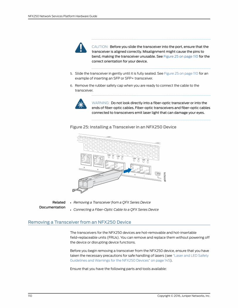
CAUTION: Before you slide the transceiver into the port, ensure that thetransceiver is aligned correctly. Misalignmentmight cause the pins tobend, making the transceiver unusable. See Figure 25 on page 110 for thecorrect orientation for your device.
5. Slide the transceiver in gently until it is fully seated. See Figure 25 on page 110 for an
example of inserting an SFP or SFP+ transceiver.
6. Remove the rubber safety cap when you are ready to connect the cable to the
transceiver.
WARNING: Do not look directly into a fiber-optic transceiver or into theends of fiber-optic cables. Fiber-optic transceivers and fiber-optic cablesconnected to transceivers emit laser light that can damage your eyes.
Figure 25: Installing a Transceiver in an NFX250 Device
RelatedDocumentation
Removing a Transceiver from a QFX Series Device•
• Connecting a Fiber-Optic Cable to a QFX Series Device
Removing a Transceiver from an NFX250 Device
The transceivers for the NFX250 devices are hot-removable and hot-insertable
field-replaceable units (FRUs). You can remove and replace themwithout powering off
the device or disrupting device functions.
Before you begin removing a transceiver from the NFX250 device, ensure that you have
taken the necessary precautions for safe handling of lasers (see “Laser and LED Safety
Guidelines andWarnings for the NFX250 Devices” on page 145).
Ensure that you have the following parts and tools available:
Copyright © 2016, Juniper Networks, Inc.110
NFX250 Network Services Platform Hardware Guide

• Electrostatic bag or an antistatic mat
• Rubber safety caps to cover the transceiver and fiber-optic cable connector
• Dust cover to cover the port
To remove a transceiver from the NFX250 device:
1. Place the antistatic bag or antistatic mat on a flat, stable surface.
2. Label the cable connected to the transceiver so that you can reconnect it correctly.
WARNING: Do not look directly into a fiber-optic transceiver or into theends of fiber-optic cables. Fiber-optic transceivers and fiber-optic cablesconnected to transceivers emit laser light that can damage your eyes.
WARNING: Do not leave a fiber-optic transceiver uncovered exceptwheninserting or removing a cable. The rubber safety cap keeps the port cleanand prevents accidental exposure to laser light.
CAUTION: Do not bend fiber-optic cables beyond their minimum bendradius.Bending thecablesbeyondtheirminimumbend radiuscandamagethe cables and cause problems that are difficult to diagnose.
3. Remove the cable connected to the transceiver (see “Disconnecting a Fiber-Optic
Cable fromanNFX250Device”onpage 114).Cover the transceiver and theendofeach
fiber-optic cable connector with a rubber safety cap immediately after disconnecting
the fiber-optic cables.
4. Using your fingers, pull the ejector lever away from the transceiver to unlock the
transceiver.
CAUTION: Before removingthetransceiver,makesureyouopentheejectorlever completely until you hear it click. This prevents damage to thetransceiver.
5. Grasp the transceiver ejector lever and gently slide the transceiver approximately
0.5 in. (1.3 cm) straight out of the port (see Figure 26 on page 112).
CAUTION: To avoid electrostatic discharge (ESD) damage to thetransceiver, do not touch the connector pins at the end of the transceiver.
6. Using your fingers, grasp the body of the transceiver and pull it straight out of the port.
111Copyright © 2016, Juniper Networks, Inc.
Chapter 15: Replacing Transceiver

7. Place the transceiver in the electrostatic bag or on the antistaticmat placed on a flat,
stable surface.
8. Place the dust cover over the empty port.
Figure 26: Removing a Transceiver from an NFX250 Device
RelatedDocumentation
• Installing a Transceiver in an NFX250 Device on page 109
Copyright © 2016, Juniper Networks, Inc.112
NFX250 Network Services Platform Hardware Guide
CHAPTER 16
Maintaining and Replacing Fiber-OpticCable
• Connecting a Fiber-Optic Cable to an NFX250 Device on page 113
• Disconnecting a Fiber-Optic Cable from an NFX250 Device on page 114
• Maintaining Fiber-Optic Cables in an NFX250 Device on page 115
Connecting a Fiber-Optic Cable to an NFX250 Device
Youcanconnect fiber-optic cables to the field-replaceableunit (FRU)optical transceivers
installed in NFX250 devices.
Before you connect a fiber-optic cable to an optical transceiver installed in an NFX250
device, ensure that you have taken the necessary precautions for safe handling of lasers
(see“LaserandLEDSafetyGuidelinesandWarnings for theNFX250Devices”onpage 145).
To connect a fiber-optic cable to an optical transceiver installed in an NFX250 device:
WARNING: Do not look directly into a fiber-optic transceiver or into the endsof fiber-opticcables.Fiber-optic transceiversandfiber-opticcablesconnectedto transceivers emit laser light that can damage your eyes.
WARNING: Do not stare into the laser beam or view it directly with opticalinstruments even if the interface has been disabled.
1. If the fiber-optic cable connector is covered by a rubber safety cap, remove the cap.
Save the cap.
2. If the optical transceiver is covered by a rubber safety cap, remove the cap. Save the
cap.
3. Insert the cable connector into the optical transceiver (see Figure 27 on page 114).
4. Secure thecables so that theyarenot supporting their ownweight. Placeexcess cable
outof theway inaneatly coiled loop.Placing fastenersona loophelps cablesmaintain
their shape.
113Copyright © 2016, Juniper Networks, Inc.

CAUTION: Do not bend fiber-optic cables beyond their minimum bendradius.Bending thecablesbeyondtheirminimumbend radiuscandamagethe cables and cause problems that are difficult to diagnose.
CAUTION: Do not let fiber-optic cables hang free from the connector. Donot allow fastened loops of cables to dangle, which stresses the cablesat the fastening point.
Figure 27: Inserting a Fiber-Optic Cable into a Transceiver
RelatedDocumentation
Disconnecting a Fiber-Optic Cable from an NFX250 Device on page 114•
• Maintaining Fiber-Optic Cables in an NFX250 Device on page 115
Disconnecting a Fiber-Optic Cable from an NFX250 Device
Before you disconnect a fiber-optic cable from an optical transceiver installed in an
NFX250 device, ensure that you have taken the necessary precautions for safe handling
of lasers (see “Laser and LED Safety Guidelines andWarnings for the NFX250 Devices”
on page 145).
Ensure that you have the following parts and tools available:
• Rubber safety cap to cover the transceiver
• Rubber safety cap to cover the fiber-optic cable connector
Copyright © 2016, Juniper Networks, Inc.114
NFX250 Network Services Platform Hardware Guide

To disconnect a fiber-optic cable from an optical transceiver installed in the NFX250
device:
1. (Recommended) Disable the port in which the transceiver is installed by including
the disable statement at the [edit interfaces] hierarchy level for the specific interface.
WARNING: Do not look directly into a fiber-optic transceiver or into theends of fiber-optic cables. Fiber-optic transceivers and fiber-optic cablesconnected to transceivers emit laser light that can damage your eyes.
WARNING: Donot stare into the laser beamor view it directlywith opticalinstruments even if the interface has been disabled.
2. Carefully unplug the fiber-optic cable connector from the transceiver.
3. Cover the transceiver with a rubber safety cap.
WARNING: Do not leave a fiber-optic transceiver uncovered exceptwheninserting or removing a cable. The rubber safety cap keeps the port cleanand prevents accidental exposure to laser light.
4. Cover the fiber-optic cable connector with the rubber safety cap.
RelatedDocumentation
Installing a Transceiver in an NFX250 Device on page 109•
• Maintaining Fiber-Optic Cables in an NFX250 Device on page 115
Maintaining Fiber-Optic Cables in an NFX250 Device
Tomaintain fiber-optic cables in NFX250 devices:
• When you unplug a fiber-optic cable from a transceiver, place rubber safety caps over
the transceiver and on the end of the cable.
• Anchor fiber-optic cable toavoid stresson theconnectors.Whenattachinga fiber-optic
cable to a transceiver, be sure to secure the fiber-optic cable so that it is not supporting
its own weight as it hangs to the floor. Never let a fiber-optic cable hang free from the
connector.
• Donot bend fiber-optic cables beyond theirminimumbend radius. Bending the cables
beyond their minimum bend radius can damage the cables and cause problems that
are difficult to diagnose.
• Frequentpluggingandunpluggingof fiber-optic cables inandoutofoptical instruments
can damage the instruments, which are expensive to repair. Attach a short fiber
extension to the optical equipment. Any wear and tear due to frequent plugging and
115Copyright © 2016, Juniper Networks, Inc.
Chapter 16: Maintaining and Replacing Fiber-Optic Cable

unplugging is then absorbed by the short fiber extension, which is easier and less
expensive to replace than the instruments.
• Keep fiber-optic cable connections clean. Microdeposits of oil and dust in the canal of
the transceiver or cable connector can cause loss of light, reduction in signal power,
and possibly intermittent problems with the optical connection.
Toclean the transceiver canal, useanappropriate fiber-cleaningdevice suchasRIFOCS
Fiber Optic Adaptor CleaningWands (part number 946). Follow the directions in the
cleaning kit you use.
After cleaning the transceiver,make sure that the connector tip of the fiber-optic cable
is clean. Use only an approved alcohol-free fiber-optic cable cleaning kit such as the
Cletop-S®Fiber Cleaner. Follow the directions in the cleaning kit you use.
RelatedDocumentation
• Disconnecting a Fiber-Optic Cable from an NFX250 Device on page 114
• Maintaining Fiber-Optic Cables in an NFX250 Device on page 115
Copyright © 2016, Juniper Networks, Inc.116
NFX250 Network Services Platform Hardware Guide

CHAPTER 17
Contacting Customer Support andReturning the Chassis or Components
• Returning a NFX250 Device or Component for Repair or Replacement on page 117
• Locating the Serial Number on an NFX250 Device on page 118
• Packing a NFX250 Device or Component for Shipping on page 119
• ContactingCustomerSupport toObtainaReturnMaterialsAuthorization foranNFX250
Device on page 120
Returning a NFX250 Device or Component for Repair or Replacement
If you need to return a NFX250 device or component to Juniper Networks for repair or
replacement, follow this procedure:
1. Determine theserial numberof thedeviceorcomponent. For instructions, see “Locating
the Serial Number on an NFX250 Device” on page 118.
2. Obtain a Return Materials Authorization (RMA) number from the Juniper Technical
Assistance Center (JTAC) as described in “Contacting Customer Support to Obtain
a Return Materials Authorization for an NFX250 Device” on page 120.
NOTE: Donot return anydevice or component to JuniperNetworks unlessyou have first obtained an RMA number. Juniper Networks reserves theright to refuse shipments that do not have an RMA. Refused shipmentsare returned to the customer through collect freight.
3. Pack theNFX250deviceor component for shippingasdescribed in “PackingaNFX250
Device or Component for Shipping” on page 119.
Formore information about return and repair policies, see the customer support page at
http://www.juniper.net/support/guidelines.html .
RelatedDocumentation
NFX250 Device Hardware Overview on page 3•
117Copyright © 2016, Juniper Networks, Inc.
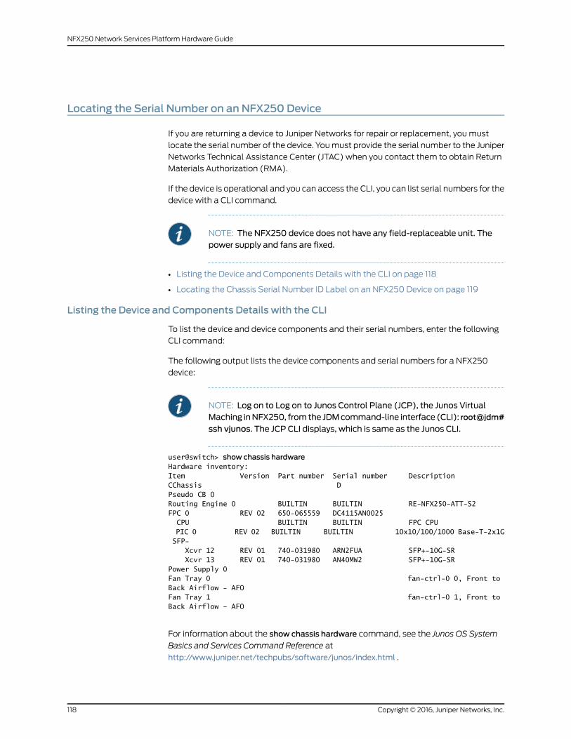
Locating the Serial Number on an NFX250 Device
If you are returning a device to Juniper Networks for repair or replacement, youmust
locate the serial number of the device. Youmust provide the serial number to the Juniper
Networks Technical Assistance Center (JTAC) when you contact them to obtain Return
Materials Authorization (RMA).
If the device is operational and you can access the CLI, you can list serial numbers for the
device with a CLI command.
NOTE: The NFX250 device does not have any field-replaceable unit. Thepower supply and fans are fixed.
• Listing the Device and Components Details with the CLI on page 118
• Locating the Chassis Serial Number ID Label on an NFX250 Device on page 119
Listing the Device and Components Details with the CLI
To list the device and device components and their serial numbers, enter the following
CLI command:
The following output lists the device components and serial numbers for a NFX250
device:
NOTE: Log on to Log on to Junos Control Plane (JCP), the Junos VirtualMaching inNFX250, fromthe JDMcommand-line interface (CLI): root@jdm#
ssh vjunos. The JCP CLI displays, which is same as the Junos CLI.
user@switch> show chassis hardwareHardware inventory:Item Version Part number Serial number DescriptionCChassis D Pseudo CB 0 Routing Engine 0 BUILTIN BUILTIN RE-NFX250-ATT-S2FPC 0 REV 02 650-065559 DC4115AN0025 CPU BUILTIN BUILTIN FPC CPU PIC 0 REV 02 BUILTIN BUILTIN 10x10/100/1000 Base-T-2x1G SFP- Xcvr 12 REV 01 740-031980 ARN2FUA SFP+-10G-SR Xcvr 13 REV 01 740-031980 AN40MW2 SFP+-10G-SRPower Supply 0 Fan Tray 0 fan-ctrl-0 0, Front to Back Airflow - AFOFan Tray 1 fan-ctrl-0 1, Front to Back Airflow – AFO
For information about the show chassis hardware command, see the Junos OS System
Basics and Services Command Reference at
http://www.juniper.net/techpubs/software/junos/index.html .
Copyright © 2016, Juniper Networks, Inc.118
NFX250 Network Services Platform Hardware Guide

Locating the Chassis Serial Number ID Label on an NFX250 Device
The serial number ID label is located on the back of the chassis on an NFX250 device.
See Figure 28 on page 119.
Figure 28: Location of the Serial Number ID Label on an NFX250 Device
RelatedDocumentation
ContactingCustomerSupport toObtainaReturnMaterialsAuthorization foranNFX250
Device on page 120
•
Packing a NFX250 Device or Component for Shipping
If you are returning a NFX250 device or component to Juniper Networks for repair or
replacement, pack the item as described in this topic.
Before you pack a NFX250 device or component:
• Ensure that youhave taken thenecessaryprecautions topreventelectrostaticdischarge
(ESD) damage. See “Prevention of Electrostatic Discharge Damage” on page 159.
• Retrieve the original shipping carton and packing materials. Contact your JTAC
representative if you do not have these materials, to learn about approved packing
materials.See “ContactingCustomerSupport toObtainaReturnMaterialsAuthorization
for an NFX250 Device” on page 120.
Ensure that you have the following parts and tools available:
• ESD grounding strap.
• Antistatic bag, one for each component.
• If you are returning the chassis, an appropriate screwdriver for the mounting screws
used on your rack or cabinet.
This topic describes:
• Packing a NFX250 Device for Shipping on page 119
• Packing NFX250 Device Components for Shipping on page 120
Packing a NFX250 Device for Shipping
To pack a NFX250 device for shipping:
119Copyright © 2016, Juniper Networks, Inc.
Chapter 17: Contacting Customer Support and Returning the Chassis or Components

1. Power down the NFX250 device and remove the power cables. See “Powering Off an
NFX250 Device” on page 105.
2. Remove the cables that connect the device to all external devices.
3. Remove all field-replaceable units (FRUs) from the NFX250 device.
4. Haveoneperson support theweight of thedevicewhile another personunscrewsand
removes the mounting screws.
5. Remove thedevice fromthe rackor cabinet (see “Chassis LiftingGuidelines forNFX250
Devices” on page 138) and place the device in an antistatic bag.
6. Place the device in the shipping carton.
7. Place the packing foam on top and around the device.
8. If you are returning accessories or FRUs with the device, pack them as instructed in
“Packing NFX250 Device Components for Shipping” on page 120.
9. Replace the accessory box on top of the packing foam.
10. Close the top of the cardboard shipping box and seal it with packing tape.
11. Write the RMA number on the exterior of the box to ensure proper tracking.
Packing NFX250 Device Components for Shipping
CAUTION: Do not stack the NFX250 device components. Return individualcomponents in separate boxes if they do not fit together on one level in theshipping box.
To pack and ship NFX250 device components:
• Place individual FRUs in antistatic bags.
• Ensure that the components are adequately protected with packing materials and
packed so that the pieces are prevented frommoving around inside the carton.
• Close the top of the cardboard shipping box and seal it with packing tape.
• Write the RMA number on the exterior of the box to ensure proper tracking.
RelatedDocumentation
Returning a NFX250 Device or Component for Repair or Replacement on page 117•
ContactingCustomerSupport toObtainaReturnMaterialsAuthorizationforanNFX250Device
If you are returning a NFX250 device or component to Juniper Networks for repair or
replacement, obtain a Return Materials Authorization (RMA) from the Juniper Networks
Technical Assistance Center (JTAC).
Copyright © 2016, Juniper Networks, Inc.120
NFX250 Network Services Platform Hardware Guide

After locating the serial number of the device or component you want to return, open a
case with Juniper Networks Technical Assistance Center (JTAC) on theWeb or by
telephone.
For instructions on locating the serial number of the device or component you want to
return, see “Locating the Serial Number on an NFX250 Device” on page 118.
Before you request an RMA from JTAC, be prepared to provide the following information:
• Your existing case number, if you have one
• Serial number of the component
• Your name, organization name, telephone number, fax number, and shipping address
• Details of the failure or problem
• Type of activity being performed on the device when the problem occurred
• Configuration data displayed by one or more show commands
You can contact JTAC 24 hours a day, seven days a week on theWeb or by telephone:
• Case Manager at CSC: http://www.juniper.net/cm/
• Telephone: +1-888-314-JTAC (+1-888-314-5822), toll-free in the USA, Canada, and
Mexico
NOTE: For international or direct-dial options in countries without toll-freenumbers, see http://www.juniper.net/support/requesting-support.html .
If you are contacting JTAC by telephone, enter your 11-digit case number followed by the
pound (#) key for an existing case, or press the star (*) key to be routed to the next
available support engineer.
The support representative validates your request and issues an RMA number for return
of the component.
RelatedDocumentation
• Returning a NFX250 Device or Component for Repair or Replacement on page 117
121Copyright © 2016, Juniper Networks, Inc.
Chapter 17: Contacting Customer Support and Returning the Chassis or Components

Copyright © 2016, Juniper Networks, Inc.122
NFX250 Network Services Platform Hardware Guide

PART 5
Troubleshooting
• AlarmMessages on page 125
123Copyright © 2016, Juniper Networks, Inc.

Copyright © 2016, Juniper Networks, Inc.124
NFX250 Network Services Platform Hardware Guide
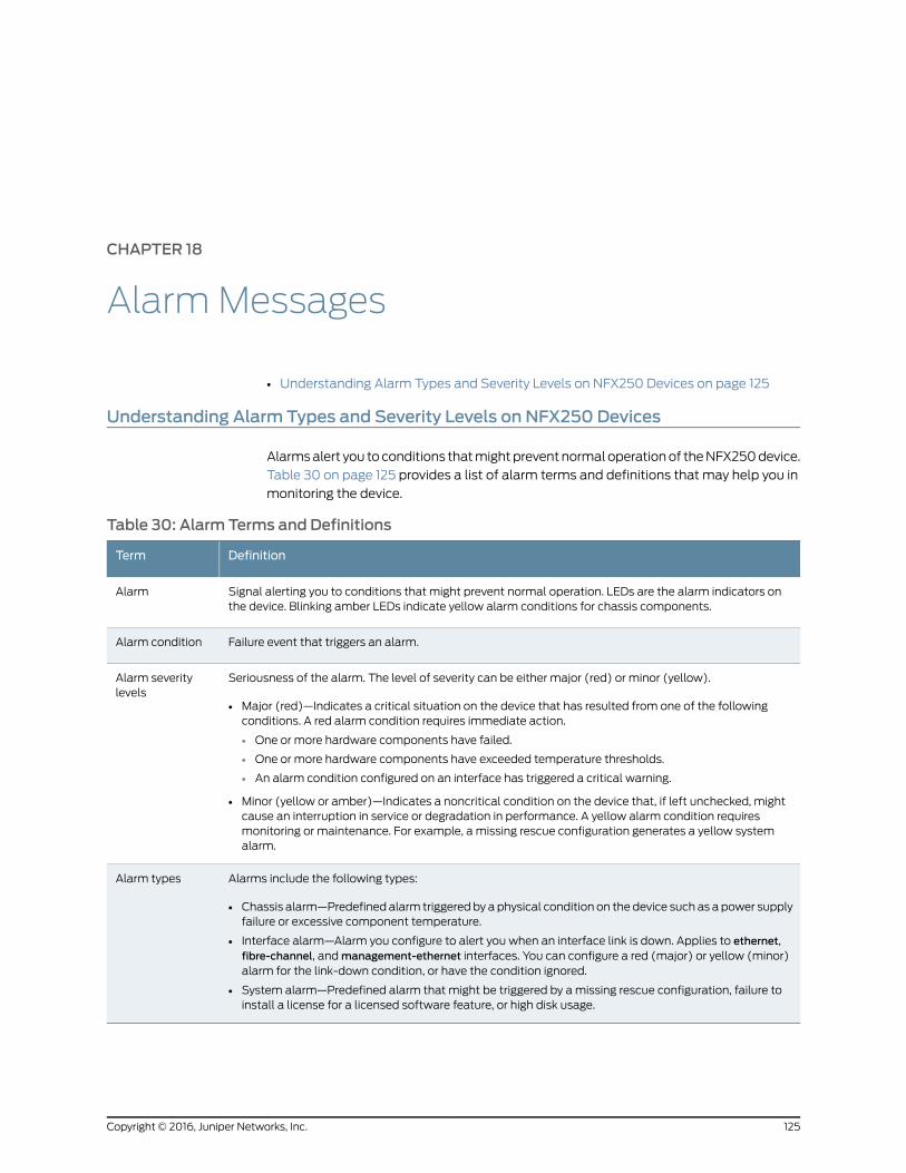
CHAPTER 18
AlarmMessages
• Understanding Alarm Types and Severity Levels on NFX250 Devices on page 125
Understanding Alarm Types and Severity Levels on NFX250 Devices
Alarmsalert you toconditions thatmightpreventnormaloperationof theNFX250device.
Table 30 on page 125 provides a list of alarm terms and definitions that may help you in
monitoring the device.
Table 30: Alarm Terms and Definitions
DefinitionTerm
Signal alerting you to conditions that might prevent normal operation. LEDs are the alarm indicators onthe device. Blinking amber LEDs indicate yellow alarm conditions for chassis components.
Alarm
Failure event that triggers an alarm.Alarm condition
Seriousness of the alarm. The level of severity can be either major (red) or minor (yellow).
• Major (red)—Indicates a critical situation on the device that has resulted from one of the followingconditions. A red alarm condition requires immediate action.
• One or more hardware components have failed.
• One or more hardware components have exceeded temperature thresholds.
• An alarm condition configured on an interface has triggered a critical warning.
• Minor (yellow or amber)—Indicates a noncritical condition on the device that, if left unchecked, mightcause an interruption in service or degradation in performance. A yellow alarm condition requiresmonitoring or maintenance. For example, a missing rescue configuration generates a yellow systemalarm.
Alarm severitylevels
Alarms include the following types:
• Chassis alarm—Predefined alarm triggered by a physical condition on the device such as a power supplyfailure or excessive component temperature.
• Interface alarm—Alarm you configure to alert you when an interface link is down. Applies to ethernet,fibre-channel, andmanagement-ethernet interfaces. You can configure a red (major) or yellow (minor)alarm for the link-down condition, or have the condition ignored.
• System alarm—Predefined alarm that might be triggered by amissing rescue configuration, failure toinstall a license for a licensed software feature, or high disk usage.
Alarm types
125Copyright © 2016, Juniper Networks, Inc.

RelatedDocumentation
• NFX250 Device Hardware Overview on page 3
Copyright © 2016, Juniper Networks, Inc.126
NFX250 Network Services Platform Hardware Guide

PART 6
Safety and Compliance Information
• General Safety Guidelines andWarnings on page 129
• Fire Safety Requirements on page 135
• Installation Safety Guidelines andWarnings on page 137
• Radiation and Laser Safety Guidelines andWarnings on page 145
• Maintenance and Operational SafetyWarnings on page 151
• Electrical Safety Guidelines andWarnings on page 157
• Agency Approvals and Compliance Statements on page 163
127Copyright © 2016, Juniper Networks, Inc.

Copyright © 2016, Juniper Networks, Inc.128
NFX250 Network Services Platform Hardware Guide

CHAPTER 19
General Safety Guidelines andWarnings
• General Safety Guidelines andWarnings on page 129
• Definitions of SafetyWarning Levels on page 130
• Qualified Personnel Warning on page 132
• Warning Statement for Norway and Sweden on page 133
General Safety Guidelines andWarnings
The following guidelines help ensure your safety and protect the device from damage.
The list of guidelinesmightnotaddressall potentially hazardoussituations in yourworking
environment, so be alert and exercise good judgment at all times.
• Perform only the procedures explicitly described in the hardware documentation for
this device. Make sure that only authorized service personnel perform other system
services.
• Keep the area around the device clear and free from dust before, during, and after
installation.
• Keep tools away from areas where people could trip over themwhile walking.
• Do not wear loose clothing or jewelry, such as rings, bracelets, or chains, which could
become caught in the device.
• Wear safety glasses if you are working under any conditions that could be hazardous
to your eyes.
• Do not perform any actions that create a potential hazard to people or make the
equipment unsafe.
• Never attempt to lift an object that is too heavy for one person to handle.
• Never install or manipulate wiring during electrical storms.
• Never install electrical jacks in wet locations unless the jacks are specifically designed
for wet environments.
• Operate the device only when it is properly grounded.
• Ensure that the separate protective earthing terminal provided on this device is
permanently connected to earth.
• Replace fuses only with fuses of the same type and rating.
129Copyright © 2016, Juniper Networks, Inc.

• Do not open or remove chassis covers or sheet-metal parts unless instructions are
provided in the hardware documentation for this device. Such an action could cause
severe electrical shock.
• Do not push or force any objects through any opening in the chassis frame. Such an
action could result in electrical shock or fire.
• Avoid spilling liquid onto the chassis or onto any device component. Such an action
could cause electrical shock or damage the device.
• Avoid touching uninsulated electrical wires or terminals that have not been
disconnected from their power source. Such an action could cause electrical shock.
• Always ensure that all modules, power supplies, and cover panels are fully inserted
and that the installation screws are fully tightened.
RelatedDocumentation
AC Power Electrical Safety Guidelines on page 160•
• DC Power Electrical Safety Guidelines for Switches
• General Electrical Safety Guidelines andWarnings on page 157
• Maintenance and Operational Safety Guidelines andWarnings on page 151
• Installation InstructionsWarning on page 137
• Grounded EquipmentWarning
Definitions of SafetyWarning Levels
The documentation uses the following levels of safety warnings (there are twoWarning
formats):
NOTE: Youmight find this information helpful in a particular situation, or youmight overlook this important information if it was not highlighted in a Note.
CAUTION: You need to observe the specified guidelines to prevent minorinjury or discomfort to you or severe damage to the device.
WARNING: This symbol alerts you to the risk of personal injury from a laser.
WARNING: This symbolmeansdanger.Youare inasituation thatcouldcausebodily injury. Before you work on any equipment, be aware of the hazardsinvolved with electrical circuitry and be familiar with standard practices forpreventing accidents.
Copyright © 2016, Juniper Networks, Inc.130
NFX250 Network Services Platform Hardware Guide

Waarschuwing Dit waarschuwingssymbool betekent gevaar. U verkeert ineen situatie die lichamelijk letsel kan veroorzaken. Voordat u aan enigeapparatuur gaat werken, dient u zich bewust te zijn van de bij elektrischeschakelingen betrokken risico's en dient u opde hoogte te zijn van standaardmaatregelen om ongelukken te voorkomen.
Varoitus Tämä varoitusmerkki merkitsee vaaraa. Olet tilanteessa, joka voijohtaa ruumiinvammaan.Ennenkuin työskenteletminkään laitteistonparissa,ota selvää sähkökytkentöihin liittyvistä vaaroista ja tavanomaisistaonnettomuuksien ehkäisykeinoista.
AttentionCe symbole d'avertissement indique un danger. Vous vous trouvezdansunesituationpouvantcauserdesblessuresoudesdommagescorporels.Avant de travailler sur un équipement, soyez conscient des dangers poséspar les circuits électriques et familiarisez-vous avec les procédurescouramment utilisées pour éviter les accidents.
Warnung DiesesWarnsymbol bedeutet Gefahr. Sie befinden sich in einerSituation, die zu einer Körperverletzung führen könnte. Bevor Sie mit derArbeit an irgendeinemGerät beginnen, seien Sie sich der mit elektrischenStromkreisen verbundenen Gefahren und der Standardpraktiken zurVermeidung von Unfällen bewußt.
AvvertenzaQuesto simbolo di avvertenza indica un pericolo. La situazionepotrebbe causare infortuni alle persone. Prima di lavorare su qualsiasiapparecchiatura, occorre conoscere i pericoli relativi ai circuiti elettrici edessere al corrente delle pratiche standard per la prevenzione di incidenti.
AdvarselDette varselsymbolet betyr fare. Du befinner deg i en situasjon somkan føre til personskade. Før du utfører arbeid på utstyr, må du vareoppmerksom på de faremomentene som elektriske kretser innebærer, samtgjøre deg kjent med vanlig praksis når det gjelder å unngå ulykker.
Aviso Este símbolo de aviso indica perigo. Encontra-se numa situação quelhepoderá causar danos físicos. Antes de começar a trabalhar comqualquerequipamento, familiarize-se com os perigos relacionados com circuitoseléctricos, e com quaisquer práticas comuns que possam prevenir possíveisacidentes.
¡Atención! Este símbolo de aviso significa peligro. Existe riesgo para suintegridad física. Antes demanipular cualquier equipo, considerar los riesgosque entraña la corriente eléctrica y familiarizarse con los procedimientosestándar de prevención de accidentes.
Varning!Denna varningssymbol signalerar fara. Du befinner dig i en situationsom kan leda till personskada. Innan du utför arbete på någon utrustningmåste du varamedveten om farornamed elkretsar och känna till vanligtförfarande för att förebygga skador.
131Copyright © 2016, Juniper Networks, Inc.
Chapter 19: General Safety Guidelines andWarnings

RelatedDocumentation
General Safety Guidelines andWarnings on page 129•
• Installation InstructionsWarning on page 137
• Maintenance and Operational Safety Guidelines andWarnings on page 151
• Grounded EquipmentWarning
• Laser and LED Safety Guidelines andWarnings
• Laser and LED Safety Guidelines andWarnings for the QFX Series
• Warning Statement for Norway and Sweden on page 133
Qualified PersonnelWarning
WARNING: Only trainedandqualified personnel should install or replace thedevice.
Waarschuwing Installatie en reparaties mogen uitsluitend door getraind enbevoegd personeel uitgevoerd worden.
VaroitusAinoastaankoulutettu japätevähenkilökuntasaaasentaatai vaihtaatämän laitteen.
Attention Tout installation ou remplacement de l'appareil doit être réalisépar du personnel qualifié et compétent.
WarnungGerät nur vongeschultem, qualifiziertemPersonal installierenoderauswechseln lassen.
Avvertenza Solo personale addestrato e qualificato deve essere autorizzatoad installare o sostituire questo apparecchio.
Advarsel Kun kvalifisert personell med riktig opplæring bør montere ellerbytte ut dette utstyret.
Aviso Este equipamento deverá ser instalado ou substituído apenas porpessoal devidamente treinado e qualificado.
¡Atención! Estos equipos deben ser instalados y reemplazadosexclusivamenteporpersonal técnicoadecuadamentepreparadoycapacitado.
Varning! Denna utrustning ska endast installeras och bytas ut av utbildadoch kvalificerad personal.
RelatedDocumentation
General Safety Guidelines andWarnings on page 129•
• General Electrical Safety Guidelines andWarnings on page 157
• AC Power Electrical Safety Guidelines on page 160
• DC Power Electrical Safety Guidelines for Switches
Copyright © 2016, Juniper Networks, Inc.132
NFX250 Network Services Platform Hardware Guide
Warning Statement for Norway and Sweden
WARNING: The equipmentmust be connected to an earthedmainssocket-outlet.
Advarsel Apparatet skal kobles til en jordet stikkontakt.
Varning! Apparaten skall anslutas till jordat nätuttag.
RelatedDocumentation
• General Safety Guidelines andWarnings on page 129
133Copyright © 2016, Juniper Networks, Inc.
Chapter 19: General Safety Guidelines andWarnings

Copyright © 2016, Juniper Networks, Inc.134
NFX250 Network Services Platform Hardware Guide

CHAPTER 20
Fire Safety Requirements
• Fire Safety Requirements on page 135
Fire Safety Requirements
In the event of a fire emergency, the safety of people is the primary concern. You should
establishprocedures for protectingpeople in theeventof a fire emergency, provide safety
training, and properly provision fire-control equipment and fire extinguishers.
In addition, you should establish procedures to protect your equipment in the event of a
fire emergency. JuniperNetworksproducts shouldbe installed inanenvironment suitable
for electronic equipment. We recommend that fire suppression equipment be available
in the event of a fire in the vicinity of the equipment and that all local fire, safety, and
electrical codesandordinancesbeobservedwhenyou install andoperateyourequipment.
Fire Suppression
In the event of an electrical hazard or an electrical fire, you should first turn power off to
theequipmentat the source. ThenuseaTypeC fire extinguisher,whichusesnoncorrosive
fire retardants, to extinguish the fire.
Fire Suppression Equipment
Type C fire extinguishers, which use noncorrosive fire retardants such as carbon dioxide
andHalotron™,aremosteffective for suppressingelectrical fires. TypeC fire extinguishers
displace oxygen from the point of combustion to eliminate the fire. For extinguishing fire
on or around equipment that draws air from the environment for cooling, you should use
this type of inert oxygen displacement extinguisher instead of an extinguisher that leaves
residues on equipment.
Do not use multipurpose Type ABC chemical fire extinguishers (dry chemical fire
extinguishers). The primary ingredient in these fire extinguishers is monoammonium
phosphate,which is very sticky anddifficult to clean. In addition, in thepresenceofminute
amounts of moisture, monoammonium phosphate can become highly corrosive and
corrodes most metals.
Any equipment in a room in which a chemical fire extinguisher has been discharged is
subject to premature failure and unreliable operation. The equipment is considered to
be irreparably damaged.
135Copyright © 2016, Juniper Networks, Inc.

NOTE: Tokeepwarrantieseffective,donotuseadrychemical fireextinguisherto control a fire at or near a Juniper Networks device. If a dry chemical fireextinguisher is used, the unit is no longer eligible for coverage under a serviceagreement.
We recommend that you dispose of any irreparably damaged equipment in an
environmentally responsible manner.
RelatedDocumentation
• General Safety Guidelines andWarnings on page 129
• General Electrical Safety Guidelines andWarnings on page 157
• Action to Take After an Electrical Accident on page 158
Copyright © 2016, Juniper Networks, Inc.136
NFX250 Network Services Platform Hardware Guide
CHAPTER 21
Installation Safety Guidelines andWarnings
• Installation InstructionsWarning on page 137
• Chassis Lifting Guidelines for NFX250 Devices on page 138
• Restricted AccessWarning on page 138
• RampWarning on page 140
• Rack-Mounting and Cabinet-MountingWarnings on page 140
Installation InstructionsWarning
WARNING: Read the installation instructions before you connect the deviceto a power source.
WaarschuwingRaadpleegde installatie-aanwijzingenvoordatuhetsysteemmet de voeding verbindt.
VaroitusLueasennusohjeetennen järjestelmänyhdistämistävirtalähteeseen.
AttentionAvantdebrancher lesystèmesur lasourced'alimentation,consulterles directives d'installation.
Warnung Lesen Sie die Installationsanweisungen, bevor Sie das System andie Stromquelle anschließen.
AvvertenzaConsultare le istruzionidi installazioneprimadicollegare il sistemaall'alimentatore.
Advarsel Les installasjonsinstruksjonene før systemet kobles til strømkilden.
Aviso Leia as instruções de instalação antes de ligar o sistema à sua fontede energia.
¡Atención! Ver las instrucciones de instalación antes de conectar el sistemaa la red de alimentación.
137Copyright © 2016, Juniper Networks, Inc.

Varning! Läs installationsanvisningarna innan du kopplar systemet till dessströmförsörjningsenhet.
RelatedDocumentation
General Safety Guidelines andWarnings on page 129•
• Laser and LED Safety Guidelines andWarnings
• Grounded EquipmentWarning
Chassis Lifting Guidelines for NFX250 Devices
The weight of an NFX250 device is approximately 9.4 lb (4.3 kg). Observe the following
guidelines for lifting andmoving an NFX250 device:
• Before installing the device, verify that the intended site meets the specified power,
environmental, and clearance requirements.
• Before lifting or moving the switch, disconnect all external cables.
RelatedDocumentation
General Safety Guidelines andWarnings on page 129•
• Installation InstructionsWarning on page 137
Restricted AccessWarning
WARNING: This unit is intended for installation in restricted access areas. Arestrictedaccessarea isanarea towhichaccesscanbegainedonlybyservicepersonnel through the use of a special tool, lock and key, or other means ofsecurity, andwhich is controlled by the authority responsible for the location.
WaarschuwingDit toestel isbedoeldvoor installatieopplaatsenmetbeperktetoegang.Eenplaatsmetbeperkte toegang iseenplaatswaar toegangslechtsdoor servicepersoneel verkregen kan worden door middel van een speciaalinstrument, een slot en sleutel, of een ander veiligheidsmiddel, en welkebeheerd wordt door de overheidsinstantie die verantwoordelijk is voor delocatie.
Varoitus Tämä laite on tarkoitettu asennettavaksi paikkaan, johon pääsy onrajoitettua. Paikka, johon pääsy on rajoitettua, tarkoittaa paikkaa, johon vainhuoltohenkilöstö pääsee jonkin erikoistyökalun, lukkoon sopivan avaimentai jonkin muun turvalaitteen avulla ja joka on paikasta vastuussa olevientoimivaltaisten henkilöiden valvoma.
Attention Cet appareil est à installer dans des zones d'accès réservé. Cesdernières sontdeszonesauxquelles seul lepersonneldeservicepeutaccéderen utilisant un outil spécial, unmécanisme de verrouillage et une clé, ou tout
Copyright © 2016, Juniper Networks, Inc.138
NFX250 Network Services Platform Hardware Guide
autre moyen de sécurité. L'accès aux zones de sécurité est sous le contrôlede l'autorité responsable de l'emplacement.
Warnung Diese Einheit ist zur Installation in Bereichenmit beschränktemZutritt vorgesehen. Ein Bereichmit beschränktem Zutritt ist ein Bereich, zudem nurWartungspersonal mit einem Spezialwerkzeugs, Schloß undSchlüssel oder anderer Sicherheitsvorkehrungen Zugang hat, und der vondem für die Anlage zuständigen Gremium kontrolliert wird.
AvvertenzaQuestaunitàdeveessere installata inun'areaadaccesso limitato.Un'area ad accesso limitato è un'area accessibile solo a personale diassistenza tramite un'attrezzo speciale, lucchetto, o altri dispositivi disicurezza, ed è controllata dall'autorità responsabile della zona.
Advarsel Denne enheten er laget for installasjon i områder med begrensetadgang.Etområdemedbegrensetadganggir kunadgangtil servicepersonalesom bruker et spesielt verktøy, lås og nøkkel, eller en annensikkerhetsanordning, og det kontrolleres av den autoriteten som er ansvarligfor området.
AvisoEstaunidade foi concebidapara instalaçãoemáreasdeacesso restrito.Uma área de acesso restrito é uma área à qual apenas temacesso o pessoalde serviço autorizado, que possua uma ferramenta, chave e fechaduraespecial, ou qualquer outra forma de segurança. Esta área é controlada pelaautoridade responsável pelo local.
¡Atención! Esta unidad ha sido diseñada para instalarse en áreas de accesorestringido. Área de acceso restringido significa un área a la que solamentetieneaccesoelpersonaldeserviciomediante lautilizacióndeunaherramientaespecial, cerradura con llave, o algún otromedio de seguridad, y que estábajo el control de la autoridad responsable del local.
Varning! Denna enhet är avsedd för installation i områdenmed begränsattillträde. Ett områdemed begränsat tillträde får endast tillträdas avservicepersonal med ett speciellt verktyg, lås och nyckel, eller annansäkerhetsanordning, och kontrolleras av den auktoritet som ansvarar förområdet.
RelatedDocumentation
General Safety Guidelines andWarnings on page 129•
• General Electrical Safety Guidelines andWarnings on page 157
• Installation InstructionsWarning on page 137
• Grounded EquipmentWarning
139Copyright © 2016, Juniper Networks, Inc.
Chapter 21: Installation Safety Guidelines andWarnings

RampWarning
WARNING: When installing the device, do not use a ramp inclined at morethan 10 degrees.
WaarschuwingGebruik een oprijplaat niet onder een hoek vanmeer dan 10graden.
VaroitusÄläkäytäsellaistakaltevaapintaa, jonkakaltevuusylittää 10astetta.
AttentionNe pas utiliser une rampe dont l'inclinaison est supérieure à 10degrés.
WarnungKeine Rampenmit einer Neigung vonmehr als 10 Grad verwenden.
AvvertenzaNon usare una rampa con pendenza superiore a 10 gradi.
Advarsel Bruk aldri en rampe som heller mer enn 10 grader.
AvisoNão utilize uma rampa com uma inclinação superior a 10 graus.
¡Atención!No usar una rampa inclinadamás de 10 grados
Varning! Använd inte rampmed en lutning påmer än 10 grader.
RelatedDocumentation
General Safety Guidelines andWarnings on page 129•
• Installation InstructionsWarning on page 137
• Grounded EquipmentWarning
Rack-Mounting and Cabinet-MountingWarnings
Ensure that the rack or cabinet in which the device is installed is evenly and securely
supported. Unevenmechanical loading could lead to a hazardous condition.
WARNING: To prevent bodily injury whenmounting or servicing the devicein a rack, take the following precautions to ensure that the system remainsstable. The following directives helpmaintain your safety:
• The devicemust be installed in a rack that is secured to the buildingstructure.
• Thedevice should bemountedat thebottomof the rack if it is the only unitin the rack.
Copyright © 2016, Juniper Networks, Inc.140
NFX250 Network Services Platform Hardware Guide

• Whenmounting the device on a partially filled rack, load the rack from thebottom to the topwith the heaviest component at the bottom of the rack.
• If the rack is provided with stabilizing equipment, install the stabilizersbeforemounting or servicing the device in the rack.
WaarschuwingOm lichamelijk letsel te voorkomenwanneer u dit toestel ineen rekmonteert of het daar een servicebeurt geeft, moet u specialevoorzorgsmaatregelen nemen om ervoor te zorgen dat het toestel stabielblijft. De onderstaande richtlijnen worden verstrekt om uw veiligheid teverzekeren:
• De Juniper Networks switchmoet in een stellage worden geïnstalleerd dieaan een bouwsel is verankerd.
• Dit toestel dient onderaan in het rek gemonteerd teworden als het toestelhet enige in het rek is.
• Wanneer u dit toestel in een gedeeltelijk gevuld rekmonteert, dient u hetrekvanonderennaarboven te ladenmethet zwaarsteonderdeelonderaanin het rek.
• Als het rek voorzien is van stabiliseringshulpmiddelen, dient u destabilisatoren temonteren voordat u het toestel in het rekmonteert of hetdaar een servicebeurt geeft.
VaroitusKun laiteasetetaan telineeseen taihuolletaansenollessa telineessä,onnoudatettavaerityisiävarotoimia järjestelmänvakavuudensäilyttämiseksi,jotta vältytään loukkaantumiselta. Noudata seuraavia turvallisuusohjeita:
• Juniper Networks switch on asennettava telineeseen, joka on kiinnitettyrakennukseen.
• Jos telineessä ei ole muita laitteita, aseta laite telineen alaosaan.
• Jos laite asetetaan osaksi täytettyyn telineeseen, aloita kuormittaminensen alaosasta kaikkein raskaimmalla esineellä ja siirry sitten sen yläosaan.
• Jos telinettä varten on vakaimet, asenna ne ennen laitteen asettamistatelineeseen tai sen huoltamista siinä.
Attention Pour éviter toute blessure corporelle pendant les opérations demontage ou de réparation de cette unité en casier, il convient de prendre desprécautions spécialesafindemaintenir la stabilité du système. Lesdirectivesci-dessous sont destinées à assurer la protection du personnel:
• Le rack sur lequel est monté le Juniper Networks switch doit être fixé à lastructure du bâtiment.
• Si cette unité constitue la seule unitémontéeencasier, elle doit êtreplacéedans le bas.
141Copyright © 2016, Juniper Networks, Inc.
Chapter 21: Installation Safety Guidelines andWarnings
• Si cette unité est montée dans un casier partiellement rempli, charger lecasier de bas en haut en plaçant l'élément le plus lourd dans le bas.
• Si lecasier estéquipédedispositifs stabilisateurs, installer les stabilisateursavant demonter ou de réparer l'unité en casier.
WarnungZurVermeidungvonKörperverletzungbeimAnbringenoderWartendieser Einheit in einemGestell müssen Sie besondere Vorkehrungen treffen,um sicherzustellen, daß das System stabil bleibt. Die folgenden Richtliniensollen zur Gewährleistung Ihrer Sicherheit dienen:
• Der Juniper Networks switchmuß in einemGestell installiert werden, dasin der Gebäudestruktur verankert ist.
• Wenn diese Einheit die einzige im Gestell ist, sollte sie unten im Gestellangebracht werden.
• Bei Anbringung dieser Einheit in einem zum Teil gefüllten Gestell ist dasGestell von unten nach oben zu laden, wobei das schwerste Bauteil untenim Gestell anzubringen ist.
• Wird das Gestell mit Stabilisierungszubehör geliefert, sind zuerst dieStabilisatoren zu installieren, bevor Sie die Einheit im Gestell anbringenoder sie warten.
AvvertenzaPerevitare infortuni fisici durante ilmontaggioo lamanutenzionedi questa unità in un supporto, occorre osservare speciali precauzioni pergarantire che il sistema rimanga stabile. Le seguenti direttive vengono forniteper garantire la sicurezza personale:
• Il Juniper Networks switch deve essere installato in un telaio, il quale deveessere fissato alla struttura dell'edificio.
• Questa unità deve venire montata sul fondo del supporto, se si trattadell'unica unità damontare nel supporto.
• Quando questa unità vienemontata in un supporto parzialmente pieno,caricare il supporto dal basso all'alto, con il componente più pesantesistemato sul fondo del supporto.
• Se il supporto è dotato di dispositivi stabilizzanti, installare tali dispositiviprimadimontareodiprocedereallamanutenzionedell'unitànel supporto.
AdvarselUnngå fysiske skader under montering eller reparasjonsarbeid pådenne enheten når den befinner seg i et kabinett. Vær nøyemed at systemeter stabilt. Følgende retningslinjer er gitt for å verne om sikkerheten:
• Juniper Networks switchmå installeres i et stativ som er forankret tilbygningsstrukturen.
• Denne enheten børmonteres nederst i kabinettet hvis dette er den enesteenheten i kabinettet.
Copyright © 2016, Juniper Networks, Inc.142
NFX250 Network Services Platform Hardware Guide
• Vedmontering av denne enheten i et kabinett som er delvis fylt, skalkabinettet lastes frabunnenogoppmeddentyngstekomponentennedersti kabinettet.
• Hvis kabinettet er utstyrt med stabiliseringsutstyr, skal stabilisatoreneinstalleres før montering eller utføring av reparasjonsarbeid på enheten ikabinettet.
Aviso Para se prevenir contra danos corporais aomontar ou reparar estaunidade numaestante, deverá tomar precauções especiais para se certificarde que o sistema possui um suporte estável. As seguintes directrizesajudá-lo-ão a efectuar o seu trabalho com segurança:
• O Juniper Networks switch deverá ser instalado numa prateleira fixa àestrutura do edificio.
• Esta unidade deverá ser montada na parte inferior da estante, caso sejaesta a única unidade a ser montada.
• Aomontar esta unidade numa estante parcialmente ocupada, coloque ositensmais pesados na parte inferior da estante, arrumando-os de baixopara cima.
• Se a estante possuir um dispositivo de estabilização, instale-o antes demontar ou reparar a unidade.
¡Atención! Para evitar lesiones durante el montaje de este equipo sobre unbastidor, o posteriormente durante sumantenimiento, se debeponermuchocuidado en que el sistema quede bien estable. Para garantizar su seguridad,proceda según las siguientes instrucciones:
• El Juniper Networks switch debe instalarse en un bastidor fijado a laestructura del edificio.
• Colocar el equipo en la parte inferior del bastidor, cuando sea la únicaunidad en el mismo.
• Cuandoesteequiposevayaa instalarenunbastidorparcialmenteocupado,comenzar la instalación desde la parte inferior hacia la superior colocandoel equipomás pesado en la parte inferior.
• Si el bastidor dispone de dispositivos estabilizadores, instalar éstos antesdemontaroprocederalmantenimientodel equipo instaladoenelbastidor.
Varning! För att undvika kroppsskada när du installerar eller utförunderhållsarbete på denna enhet på en ställningmåste du vidta särskildaförsiktighetsåtgärder föratt försäkradigomattsystemetstår stadigt. Följanderiktlinjer ges för att trygga din säkerhet:
143Copyright © 2016, Juniper Networks, Inc.
Chapter 21: Installation Safety Guidelines andWarnings

• Juniper Networks switchmåste installeras i en ställning som är förankradi byggnadens struktur.
• Omdenna enhet är den enda enheten på ställningen skall den installeraslängst ned på ställningen.
• Omdenna enhet installeras på en delvis fylld ställning skall ställningenfyllasnedifrånochupp,meddetyngstaenheterna längstnedpåställningen.
• Omställningenär förseddmedstabiliseringsdonskalldessamonteras fastinnan enheten installeras eller underhålls på ställningen.
RelatedDocumentation
• General Safety Guidelines andWarnings on page 129
• Installation InstructionsWarning on page 137
• Grounded EquipmentWarning
Copyright © 2016, Juniper Networks, Inc.144
NFX250 Network Services Platform Hardware Guide

CHAPTER 22
RadiationandLaserSafetyGuidelinesandWarnings
• Laser and LED Safety Guidelines andWarnings for the NFX250 Devices on page 145
• Radiation fromOpen Port AperturesWarning on page 149
Laser and LED Safety Guidelines andWarnings for the NFX250 Devices
NFX250 devices are equipped with laser transmitters:
• SFP and SFP+ transceivers are classified as Class 1 Laser Products (complies with 21
CFR 1040.10 and 1040.11 except for deviations pursuant to Laser Notice 50, dated July
26, 2001) or Class 1 LED Products.
Observe the following guidelines and warnings:
• General Laser Safety Guidelines on page 145
• Class 1M Laser ProductWarning on page 146
• Class 1M Laser RadiationWarning on page 146
• Class 1 Laser ProductWarning on page 146
• Class 1 LED ProductWarning on page 147
• Laser BeamWarning on page 147
• Unterminated Fiber-Optic CableWarning on page 148
General Laser Safety Guidelines
When working around ports that support optical transceivers, observe the following
safety guidelines to prevent eye injury:
• Do not look into unterminated ports or at fibers that connect to unknown sources.
• Do not examine unterminated optical ports with optical instruments.
• Avoid direct exposure to the beam.
WARNING: Unterminated optical connectors can emit invisible laserradiation. The lens in the human eye focuses all the laser power on the
145Copyright © 2016, Juniper Networks, Inc.

retina, so focusing the eye directly on a laser source—even a low-powerlaser—could permanently damage the eye.
Class 1M Laser ProductWarning
WARNING: Class 1M laser product.
Waarschuwing Laserproducten van Klasse 1M (IEC).
Varoitus Luokan 1M (IEC) lasertuotteita.
Attention Produits laser catégorie 1M (IEC).
Warnung Laserprodukte der Klasse 1M (IEC).
Avvertenza Prodotti laser di Classe 1M (IEC).
Advarsel Klasse 1M (IEC) laserprodukter.
Aviso Produtos laser Classe 1M (IEC).
¡Atención! Productos láser de Clase 1M (IEC).
Varning! Laserprodukter av Klass 1M (IEC).
Class 1M Laser RadiationWarning
WARNING: Class 1M laser radiation when open. Do not view directly withoptical instruments.
Class 1 Laser ProductWarning
WARNING: Class 1 laser product.
Waarschuwing Klasse-1 laser produkt.
Varoitus Luokan 1 lasertuote.
Attention Produit laser de classe I.
Warnung Laserprodukt der Klasse 1.
Avvertenza Prodotto laser di Classe 1.
Advarsel Laserprodukt av klasse 1.
Aviso Produto laser de classe 1.
Copyright © 2016, Juniper Networks, Inc.146
NFX250 Network Services Platform Hardware Guide
¡Atención! Producto láser Clase I.
Varning! Laserprodukt av klass 1.
Class 1 LED ProductWarning
WARNING: Class 1 LED product.
Waarschuwing Klasse 1 LED-product.
Varoitus Luokan 1 valodiodituote.
Attention Alarme de produit LED Class I.
Warnung Class 1 LED-Produktwarnung.
Avvertenza Avvertenza prodotto LED di Classe 1.
Advarsel LED-produkt i klasse 1.
Aviso Produto de classe 1 com LED.
¡Atención! Aviso sobre producto LED de Clase 1.
Varning! Lysdiodprodukt av klass 1.
Laser BeamWarning
WARNING: Do not stare into the laser beam or view it directly with opticalinstruments.
WaarschuwingNiet in de straal staren of hem rechtstreeks bekijkenmetoptische instrumenten.
Varoitus Älä katso säteeseen äläkä tarkastele sitä suoraan optisen laitteenavulla.
AttentionNe pas fixer le faisceau des yeux, ni l'observer directement à l'aided'instruments optiques.
WarnungNicht direkt in den Strahl blicken und ihn nicht direktmit optischenGeräten prüfen.
AvvertenzaNon fissare il raggio con gli occhi né usare strumenti ottici perosservarlo direttamente.
Advarsel Stirr eller se ikke direkte p strlenmed optiske instrumenter.
147Copyright © 2016, Juniper Networks, Inc.
Chapter 22: Radiation and Laser Safety Guidelines andWarnings

AvisoNão olhe fixamente para o raio, nem olhe para ele directamente cominstrumentos ópticos.
¡Atención!Nomirar fijamente el haz ni observarlo directamente coninstrumentos ópticos.
Varning! Rikta inte blicken in mot strålen och titta inte direkt på den genomoptiska instrument.
Unterminated Fiber-Optic CableWarning
WARNING: Invisible laser radiationmight be emitted from the unterminatedconnector of a fiber-optic cable. To avoid injury to your eye, do not view thefiber opticswith amagnifyingoptical device, suchasa loupe,within 100mm.
WaarschuwingErkunnenonzichtbare laserstralenwordenuitgezondenvanuithet uiteinde van de onafgebroken vezelkabel of connector. Niet in de straalkijken of deze rechtstreeks bekijkenmet optische instrumenten. Als u delaseruitvoer met bepaalde optische instrumenten bekijkt (zoals bijv. eenoogloep, vergrootgras of microscoop) binnen een afstand van 100mm kandit gevaar voor uw ogen opleveren.
Varoitus Päättämättömän kuitukaapelin tai -liittimen päästä voi tullanäkymätöntä lasersäteilyä. Älä tuijota sädettä tai katso sitä suoraanoptisillavälineillä. Lasersäteen katsominen tietyillä optisilla välineillä (esim.suurennuslasilla taimikroskoopilla) 10cm:npäästä tai sitä lähempäävoi ollavaarallista silmille.
Attention Des émissions de radiations laser invisibles peuvent se produire àl'extrémité d'un câble en fibre ou d'un raccord sans terminaison. Ne pas fixerdu regard le rayon ou l'observer directement avec des instruments optiques.L'observation du laser à l'aide certains instruments optiques (loupes etmicroscopes)àunedistance inférieureà 100mmpeutposerdes risquespourles yeux.
Warnung Eine unsichtbare Laserstrahlung kann vom Ende des nichtangeschlossenen Glasfaserkabels oder Steckers ausgestrahlt werden. NichtindenLaserstrahl schauenoderdiesenmiteinemoptischen Instrumentdirektansehen. Ein Betrachten des Laserstrahls mit bestimmten optischenInstrumenten, wie z.B. Augenlupen, Vergrößerungsgläsern undMikroskopeninnerhalb eines Abstands von 100mm kann für das Auge gefährlich sein.
Avvertenza L'estremità del connettore o del cavo ottico senza terminazionepuò emettere radiazioni laser invisibili. Non fissare il raggio od osservarlo inmodo diretto con strumenti ottici. L'osservazione del fascio laser condeterminati strumenti ottici (come lupette, lenti di ingrandimento omicroscopi) entro una distanza di 100mmpuò provocare danni agli occhi.
Copyright © 2016, Juniper Networks, Inc.148
NFX250 Network Services Platform Hardware Guide
AdvarselUsynlig laserstråling kan emittere fra enden av den ikke-terminertefiberkabelen eller koblingen. Ikke se inn i strålen og se heller ikke direkte påstrålenmed optiske instrumenter. Observering av laserutgangmed visseoptiske instrumenter (for eksempel øyelupe, forstørrelsesglass ellermikroskoper) innenfor en avstand på 100mm kan være farlig for øynene.
Aviso Radiação laser invisível pode ser emitida pela ponta de um conectorou cabo de fibra não terminado. Não olhe fixa ou diretamente para o feixeou com instrumentos ópticos. Visualizar a emissão do laser com certosinstrumentos ópticos (por exemplo, lupas, lentes de aumento oumicroscópios) a uma distância de 100mmpode causar riscos à visão.
¡Atención! El extremo de un cable o conector de fibra sin terminación puedeemitir radiación láser invisible. No se acerque al radio de acción ni lo miredirectamente con instrumentos ópticos. La exposición del ojo a una salidade láser con determinados instrumentos ópticos (por ejemplo, lupas ymicroscopios)aunadistanciade 100mmpuedecomportar lesionesoculares.
Varning!Osynlig laserstrålning kan komma från änden på en oavslutadfiberkabel eller -anslutning. Titta inte rakt in i strålen eller direkt på denmedoptiska instrument. Att titta på laserstrålenmed vissa optiska instrument(t.ex. lupper, förstoringsglas ochmikroskop) från ett avstånd på 100mmkanskada ögonen.
RelatedDocumentation
General Safety Guidelines andWarnings on page 129•
• Radiation fromOpen Port AperturesWarning on page 149
• Installation InstructionsWarning on page 137
• Grounded EquipmentWarning
Radiation fromOpen Port AperturesWarning
WARNING: Because invisible radiationmight be emitted from the apertureof the portwhen no fiber cable is connected, avoid exposure to radiation anddo not stare into open apertures.
Waarschuwing Aangezien onzichtbare straling vanuit de opening van depoort kan komen als er geen fiberkabel aangesloten is, dient blootstellingaan straling en het kijken in open openingen vermeden te worden.
Varoitus Koska portin aukosta voi emittoitua näkymätöntä säteilyä, kunkuitukaapelia ei ole kytkettynä, vältä säteilylle altistumista äläkä katsoavoimiin aukkoihin.
149Copyright © 2016, Juniper Networks, Inc.
Chapter 22: Radiation and Laser Safety Guidelines andWarnings

Attention Des radiations invisibles à l'il nu pouvant traverser l'ouverture duport lorsqu'aucun câble en fibre optique n'y est connecté, il est recommandéde ne pas regarder fixement l'intérieur de ces ouvertures.
Warnung Aus der Port-Öffnung können unsichtbare Strahlen emittieren,wenn kein Glasfaserkabel angeschlossen ist. Vermeiden Sie es, sich denStrahlungen auszusetzen, und starren Sie nicht in die Öffnungen!
AvvertenzaQuando i cavi in fibranonsono inseriti, radiazioni invisibili possonoessere emesse attraverso l'apertura della porta. Evitate di esporvi alleradiazioni e non guardate direttamente nelle aperture.
AdvarselUnngåutsettelse for stråling, ogstirr ikke inn i åpninger someråpne,fordi usynlig stråling kan emiteres fra portens åpning når det ikke er tilkobleten fiberkabel.
AvisoDadaapossibilidadedeemissãode radiação invisível atravésdoorifícioda via de acesso, quando esta não tiver nenhum cabo de fibra conectado,deverá evitar a exposição à radiação e não deverá olhar fixamente paraorifícios que se encontrarem a descoberto.
¡Atención!Debidoaque laaperturadelpuertopuedeemitir radiación invisiblecuando no existe un cable de fibra conectado, evitemirar directamente a lasaperturas para no exponerse a la radiación.
Varning!Osynlig strålning kan avges från en portöppning utan anslutenfiberkabel ochdubör därför undvika att bli utsatt för strålning genomatt intestirra in i oskyddade öppningar.
RelatedDocumentation
• General Safety Guidelines andWarnings on page 129
• Laser and LED Safety Guidelines andWarnings
• Installation InstructionsWarning on page 137
• Grounded EquipmentWarning
Copyright © 2016, Juniper Networks, Inc.150
NFX250 Network Services Platform Hardware Guide

CHAPTER 23
Maintenance and Operational SafetyWarnings
• Maintenance and Operational Safety Guidelines andWarnings on page 151
Maintenance and Operational Safety Guidelines andWarnings
Whileperforming themaintenanceactivities fordevices, observe the followingguidelines
and warnings:
• Battery HandlingWarning on page 151
• Jewelry Removal Warning on page 152
• Lightning Activity Warning on page 153
• Operating TemperatureWarning on page 154
• Product Disposal Warning on page 155
Battery HandlingWarning
WARNING: Replacing a battery incorrectly might result in an explosion.Replace a battery only with the same or equivalent type recommended bythemanufacturer. Disposeof usedbatteries according to themanufacturer'sinstructions.
Waarschuwing Er is ontploffingsgevaar als de batterij verkeerd vervangenwordt. Vervang de batterij slechts met hetzelfde of een equivalent type datdoor de fabrikant aanbevolen is. Gebruikte batterijendienenovereenkomstigfabrieksvoorschriften weggeworpen te worden.
Varoitus Räjähdyksen vaara, jos akku on vaihdettu väärään akkuun. Käytävaihtamiseen ainoastaan saman- tai vastaavantyyppistä akkua, joka onvalmistajansuosittelema.Hävitäkäytetytakutvalmistajanohjeidenmukaan.
Attention Danger d'explosion si la pile n'est pas remplacée correctement.Ne la remplacer que par une pile de type semblable ou équivalent,recommandée par le fabricant. Jeter les piles usagées conformément auxinstructions du fabricant.
151Copyright © 2016, Juniper Networks, Inc.

Warnung Bei Einsetzen einer falschen Batterie besteht Explosionsgefahr.Ersetzen Sie die Batterie nur durch den gleichen oder vomHerstellerempfohlenen Batterietyp. Entsorgen Sie die benutzten Batterien nach denAnweisungen des Herstellers.
Advarsel Det kan være fare for eksplosjon hvis batteriet skiftes på feil måte.Skift kunmed sammeeller tilsvarende type somer anbefalt av produsenten.Kasser brukte batterier i henhold til produsentens instruksjoner.
Avvertenza Pericolo di esplosione se la batteria non è installatacorrettamente.Sostituiresoloconunadi tipougualeoequivalente, consigliatadalproduttore. Eliminare lebatterieusatesecondo le istruzionidelproduttore.
AvisoExiste perigo de explosão se a bateria for substituída incorrectamente.Substitua a bateria por uma bateria igual ou de um tipo equivalenterecomendado pelo fabricante. Destrua as baterias usadas conforme asinstruções do fabricante.
¡Atención! Existe peligro de explosión si la batería se reemplaza demaneraincorrecta. Reemplazar la batería exclusivamente con el mismo tipo o elequivalente recomendado por el fabricante. Desechar las baterías gastadassegún las instrucciones del fabricante.
Varning!Explosionsfara vid felaktigt batteribyte. Ersätt endast batterietmedsamma batterityp som rekommenderas av tillverkaren eller motsvarande.Följ tillverkarens anvisningar vid kassering av använda batterier.
Jewelry RemovalWarning
WARNING: Before working on equipment that is connected to power lines,remove jewelry, including rings, necklaces, and watches. Metal objects heatupwhen connected to power and ground and can cause serious burns or canbe welded to the terminals.
Waarschuwing Alvorens aan apparatuur te werken die met elektrischeleidingen is verbonden, sieraden (inclusief ringen, kettingen en horloges)verwijderen. Metalen voorwerpen worden warmwanneer zemet stroom enaarde zijn verbonden, en kunnen ernstige brandwonden veroorzaken of hetmetalen voorwerp aan de aansluitklemmen lassen.
Varoitus Ennen kuin työskentelet voimavirtajohtoihin kytkettyjen laitteidenparissa, otapois kaikki korut (sormukset, kaulakorut ja kellotmukaan lukien).Metalliesineet kuumenevat, kun ne ovat yhteydessä sähkövirran ja maankanssa, janevoivataiheuttaavakaviapalovammoja tai hitsatametalliesineetkiinni liitäntänapoihin.
AttentionAvantd'accéderàcetéquipementconnectéaux lignesélectriques,ôter toutbijou(anneaux,colliersetmontrescompris). Lorsqu'ilssontbranchés
Copyright © 2016, Juniper Networks, Inc.152
NFX250 Network Services Platform Hardware Guide
à l'alimentation et reliés à la terre, les objets métalliques chauffent, ce quipeutprovoquerdesblessuresgravesousouder l'objetmétalliqueauxbornes.
Warnung Vor der Arbeit an Geräten, die an das Netz angeschlossen sind,jeglichen Schmuck (einschließlich Ringe, Ketten und Uhren) abnehmen.Metallgegenstände erhitzen sich, wenn sie an das Netz und die Erdeangeschlossen werden, und können schwere Verbrennungen verursachenoder an die Anschlußklemmen angeschweißt werden.
Avvertenza Prima di intervenire su apparecchiature collegate alle linee dialimentazione, togliersi qualsiasi monile (inclusi anelli, collane, braccialettied orologi). Gli oggetti metallici si riscaldano quando sono collegati tra puntidi alimentazione emassa: possono causare ustioni gravi oppure il metallopuò saldarsi ai terminali.
Advarsel Fjern alle smykker (inkludert ringer, halskjeder og klokker) før duskal arbeidepåutstyr somer koblet til kraftledninger.Metallgjenstander somer koblet til kraftledninger og jord blir svært varme og kan forårsake alvorligebrannskader eller smelte fast til polene.
Aviso Antes de trabalhar em equipamento que esteja ligado a linhas decorrente, retire todas as jóias que estiver a usar (incluindo anéis, fios erelógios). Os objectosmetálicos aquecerão em contacto com a corrente eem contacto com a ligação à terra, podendo causar queimaduras graves ouficarem soldados aos terminais.
¡Atención! Antes de operar sobre equipos conectados a líneas dealimentación, quitarse las joyas (incluidos anillos, collares y relojes). Losobjetosdemetal secalientancuandoseconectana laalimentaciónyatierra,lo que puede ocasionar quemaduras graves o que los objetosmetálicosqueden soldados a los bornes.
Varning! Tag av alla smycken (inklusive ringar, halsband och armbandsur)innanduarbetarpåutrustningsomärkopplad till kraftledningar.Metallobjekthettas upp när de kopplas ihopmed ström och jord och kan förorsakaallvarliga brännskador; metallobjekt kan också sammansvetsasmedkontakterna.
Lightning ActivityWarning
WARNING: Donotworkon thesystemorconnectordisconnectcablesduringperiods of lightning activity.
Waarschuwing Tijdens onweer dat gepaard gaat met bliksem, dient u nietaan het systeem te werken of kabels aan te sluiten of te ontkoppelen.
Varoitus Älä työskentele järjestelmän parissa äläkä yhdistä tai irrotakaapeleita ukkosilmalla.
153Copyright © 2016, Juniper Networks, Inc.
Chapter 23: Maintenance and Operational SafetyWarnings
AttentionNe pas travailler sur le système ni brancher ou débrancher lescâbles pendant un orage.
Warnung Arbeiten Sie nicht am System und schließen Sie keine Kabel anbzw. trennen Sie keine ab, wenn es gewittert.
AvvertenzaNon lavorare sul sistema o collegare oppure scollegare i cavidurante un temporale con fulmini.
AdvarselUtfør aldri arbeidpåsystemet, eller koble kabler til eller fra systemetnår det tordner eller lyner.
AvisoNão trabalhe no sistema ou ligue e desligue cabos durante períodosdemau tempo (trovoada).
¡Atención!No operar el sistema ni conectar o desconectar cables durante eltranscurso de descargas eléctricas en la atmósfera.
Varning!Vid åska skall du aldrig utföra arbete på systemet eller ansluta ellerkoppla loss kablar.
Operating TemperatureWarning
WARNING: To prevent the device from overheating, do not operate it in anarea that exceeds themaximum recommended ambient temperature of104° F (40° C) for EX6200 switches, EX8208 switches, EX8216 switches,QFXSeriesdevices,OCX1100switches,andXRE200ExternalRoutingEnginesand 113°F(45°C) forEX2200,EX3300,EX3200,EX4200,EX4300,EX4500,and EX4550 switches. To prevent airflow restriction, allow at least 6 in.(15.2 cm) of clearance around the ventilation openings.
WaarschuwingOm te voorkomen dat welke switch van de Juniper Networksrouter dan ook oververhit raakt, dient u deze niet te bedienen op een plaatswaar demaximale aanbevolen omgevingstemperatuur van 40° Cwordtoverschreden. Om te voorkomen dat de luchtstroomwordt beperkt, dient erminstens 15,2 cm speling rond de ventilatie-openingen te zijn.
Varoitus Ettei Juniper Networks switch-sarjan reititin ylikuumentuisi, sitä eisaa käyttää tilassa, jonka lämpötila ylittää korkeimman suositellunympäristölämpötilan 40° C. Ettei ilmanvaihto estyisi, tuuletusaukkojenympärille on jätettävä ainakin 15,2 cm tilaa.
Attention Pour éviter toute surchauffe des routeurs de la gamme JuniperNetworks switch, ne l'utilisez pas dans une zoneoù la température ambianteest supérieure à 40° C. Pour permettre un flot d'air constant, dégagez unespace d'aumoins 15,2 cm autour des ouvertures de ventilations.
WarnungUmeinenRouterder switchvorÜberhitzungzuschützen,darfdiesernicht in einer Gegend betrieben werden, in der die Umgebungstemperatur
Copyright © 2016, Juniper Networks, Inc.154
NFX250 Network Services Platform Hardware Guide

das empfohlene Maximum von 40° C überschreitet. Um Lüftungsverschlußzu verhindern, achten Sie darauf, daßmindestens 15,2 cm lichter Raum umdie Lüftungsöffnungen herum frei bleibt.
Avvertenza Per evitare il surriscaldamento dei switch, non adoperateli in unlocale che ecceda la temperatura ambientale massima di 40° C. Per evitareche lacircolazionedell'aria sia impedita, lasciateunospaziodialmeno 15.2cmdi fronte alle aperture delle ventole.
AdvarselUnngåoveropphetingaveventuelle rutere i JuniperNetworksswitchDisse skal ikke brukes på steder der den anbefalte maksimaleomgivelsestemperaturen overstiger 40° C (104° F). Sørg for at klaringenrundt lufteåpningene er minst 15,2 cm (6 tommer) for å forhindre nedsattluftsirkulasjon.
Aviso Para evitar o sobreaquecimento do encaminhador Juniper Networksswitch, não utilize este equipamento numa área que exceda a temperaturamáxima recomendada de 40° C. Para evitar a restrição à circulação de ar,deixe pelomenos um espaço de 15,2 cm à volta das aberturas de ventilação.
¡Atención! Para impedir que un encaminador de la serie Juniper Networksswitch se recaliente, no lo haga funcionar en un área en la que se supere latemperatura ambientemáxima recomendada de 40° C. Para impedir larestricciónde laentradadeaire, dejeunespaciomínimode 15,2 cmalrededorde las aperturas para ventilación.
Varning! Förhindra att en Juniper Networks switch överhettas genomatt inteanvända den i ett område där denmaximalt rekommenderadeomgivningstemperaturenpå40°Cöverskrids. Förhindraatt luftcirkulationeninskränksgenomattse till attdet finns fritt utrymmepåminst 15,2cmomkringventilationsöppningarna.
Product DisposalWarning
WARNING: Disposal of this devicemust be handled according to all nationallaws and regulations.
Waarschuwing Dit produkt dient volgens alle landelijke wetten envoorschriften te worden afgedankt.
VaroitusTämän tuotteen lopullisesta hävittämisestä tulee huolehtia kaikkiavaltakunnallisia lakeja ja säännöksiä noudattaen.
Attention Lamise au rebut définitive de ce produit doit être effectuéeconformément à toutes les lois et réglementations en vigueur.
Warnung Dieses Produkt muß den geltenden Gesetzen und Vorschriftenentsprechend entsorgt werden.
155Copyright © 2016, Juniper Networks, Inc.
Chapter 23: Maintenance and Operational SafetyWarnings

Avvertenza L'eliminazione finale di questo prodotto deve essere eseguitaosservando le normative italiane vigenti in materia
AdvarselEndeligdisponeringavdetteproduktetmåskje ihenholdtil nasjonalelover og forskrifter.
Aviso A descartagem final deste produto deverá ser efectuada de acordocom os regulamentos e a legislação nacional.
¡Atención! El desecho final de este producto debe realizarse según todas lasleyes y regulaciones nacionales
Varning!Slutlig kasseringavdennaproduktbör skötas i enlighetmed landetsalla lagar och föreskrifter.
RelatedDocumentation
• General Safety Guidelines andWarnings on page 129
• General Electrical Safety Guidelines andWarnings on page 157
• AC Power Electrical Safety Guidelines on page 160
• DC Power Electrical Safety Guidelines for Switches
• Laser and LED Safety Guidelines andWarnings
• Installation InstructionsWarning on page 137
• Grounded EquipmentWarning
Copyright © 2016, Juniper Networks, Inc.156
NFX250 Network Services Platform Hardware Guide

CHAPTER 24
Electrical SafetyGuidelines andWarnings
• General Electrical Safety Guidelines andWarnings on page 157
• Action to Take After an Electrical Accident on page 158
• Prevention of Electrostatic Discharge Damage on page 159
• AC Power Electrical Safety Guidelines on page 160
• AC Power DisconnectionWarning on page 161
• TN PowerWarning on page 162
General Electrical Safety Guidelines andWarnings
WARNING: Certain ports on the device are designed for use as intrabuilding(within-the-building) interfaces only (Type 2 or Type 4 ports as described inGR-1089-CORE) and require isolation from the exposedoutside plant (OSP)cabling. To comply with NEBS requirements and protect against lightningsurges and commercial power disturbances, the intrabuilding portsmust notbemetallically connected to interfaces that connect to theOSP or its wiring.The intrabuilding ports on the device are suitable for connection tointrabuilding or unexposed wiring or cabling only. The addition of primaryprotectors is not sufficient protection for connecting these interfacesmetallically to OSPwiring.
CAUTION: Before removing or installing components of a device, attach anelectrostatic discharge (ESD) grounding strap to an ESD point and place theother endof thestraparoundyourbarewrist. Failure touseanESDgroundingstrap could result in damage to the device.
• Install the device in compliance with the following local, national, and international
electrical codes:
• United States—National Fire Protection Association (NFPA 70), United States
National Electrical Code.
• Other countries—International Electromechanical Commission (IEC) 60364, Part 1
through Part 7.
157Copyright © 2016, Juniper Networks, Inc.

• Evaluated to the TN power system.
• Canada—Canadian Electrical Code, Part 1, CSA C22.1.
• Locate the emergency power-off switch for the room in which you are working so that
if an electrical accident occurs, you can quickly turn off the power.
• Make sure that grounding surfaces are cleaned and brought to a bright finish before
grounding connections are made.
• Donotworkalone if potentially hazardousconditionsexist anywhere in yourworkspace.
• Never assume thatpower is disconnected fromacircuit. Always check thecircuit before
starting to work.
• Carefully look for possible hazards in your work area, such asmoist floors, ungrounded
power extension cords, andmissing safety grounds.
• Operate the device within marked electrical ratings and product usage instructions.
• To ensure that the device and peripheral equipment function safely and correctly, use
the cables and connectors specified for the attached peripheral equipment, andmake
certain they are in good condition.
You can remove and replace many device components without powering off or
disconnectingpower to thedevice, asdetailedelsewhere in thehardwaredocumentation
for this device. Never install an equipment that it appears to be damaged.
RelatedDocumentation
General Safety Guidelines andWarnings on page 129•
• AC Power Electrical Safety Guidelines on page 160
• DC Power Electrical Safety Guidelines for Switches
Action to Take After an Electrical Accident
If an electrical accident results in an injury, take the following actions in this order:
1. Use caution. Be aware of potentially hazardous conditions that could cause further
injury.
2. Disconnect power from the device.
3. If possible, send another person to get medical aid. Otherwise, assess the condition
of the victim, then call for help.
RelatedDocumentation
General Safety Guidelines andWarnings on page 129•
• General Electrical Safety Guidelines andWarnings on page 157
• AC Power Electrical Safety Guidelines on page 160
• DC Power Electrical Safety Guidelines for Switches
Copyright © 2016, Juniper Networks, Inc.158
NFX250 Network Services Platform Hardware Guide
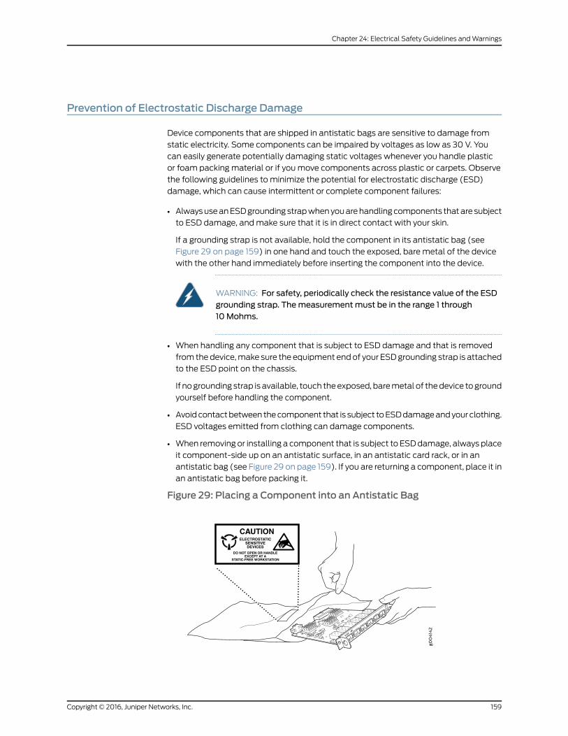
Prevention of Electrostatic Discharge Damage
Device components that are shipped in antistatic bags are sensitive to damage from
static electricity. Some components can be impaired by voltages as low as 30 V. You
can easily generate potentially damaging static voltages whenever you handle plastic
or foam packing material or if youmove components across plastic or carpets. Observe
the following guidelines to minimize the potential for electrostatic discharge (ESD)
damage, which can cause intermittent or complete component failures:
• AlwaysuseanESDgroundingstrapwhenyouarehandlingcomponents thatare subject
to ESD damage, andmake sure that it is in direct contact with your skin.
If a grounding strap is not available, hold the component in its antistatic bag (see
Figure 29 on page 159) in one hand and touch the exposed, bare metal of the device
with the other hand immediately before inserting the component into the device.
WARNING: For safety, periodically check the resistance value of the ESDgrounding strap. Themeasurementmust be in the range 1 through10Mohms.
• When handling any component that is subject to ESD damage and that is removed
from thedevice,make sure the equipment endof your ESDgrounding strap is attached
to the ESD point on the chassis.
If nogrounding strap is available, touch theexposed, baremetal of thedevice toground
yourself before handling the component.
• Avoidcontactbetween thecomponent that is subject toESDdamageandyourclothing.
ESD voltages emitted from clothing can damage components.
• When removing or installing a component that is subject to ESDdamage, always place
it component-side up on an antistatic surface, in an antistatic card rack, or in an
antistatic bag (see Figure 29 on page 159). If you are returning a component, place it in
an antistatic bag before packing it.
Figure 29: Placing a Component into an Antistatic Bag
6xGE
SFP
0
1
2
3
4
5
CAUTIONELECTROSTATIC
SENSITIVEDEVICES
DO NOT OPEN OR HANDLEEXCEPT AT A
STATIC-FREE WORKSTATION
159Copyright © 2016, Juniper Networks, Inc.
Chapter 24: Electrical Safety Guidelines andWarnings
CAUTION: ANSI/TIA/EIA-568 cables such as Category 5e and Category 6can get electrostatically charged. To dissipate this charge, always groundthe cables to a suitable and safe earth groundbefore connecting them to thesystem.
RelatedDocumentation
General Safety Guidelines andWarnings on page 129•
AC Power Electrical Safety Guidelines
CAUTION: For devices with AC power supplies, an external surge protectivedevice (SPD)must be used at the AC power source.
The following electrical safety guidelines apply to AC-powered devices:
• Note the following warnings printed on the device:
“CAUTION: THIS UNIT HASMORE THANONE POWER SUPPLY CORD. DISCONNECT
ALL POWER SUPPLY CORDS BEFORE SERVICING TO AVOID ELECTRIC SHOCK.”
“ATTENTION: CET APPAREIL COMPORTE PLUS D'UN CORDON D'ALIMENTATION.AFIN DE PRÉVENIR LES CHOCS ÉLECTRIQUES, DÉBRANCHER TOUT CORDON
D'ALIMENTATION AVANT DE FAIRE LE DÉPANNAGE.”
• AC-powereddevicesare shippedwitha three-wireelectrical cordwithagrounding-type
plug that fits only a grounding-typepower outlet. Donot circumvent this safety feature.
Equipment grounding must comply with local and national electrical codes.
• Youmustprovideanexternal certifiedcircuit breaker ratedminimum20A in thebuilding
installation.
• The power cord serves as the main disconnecting device for the AC-powered device.
The socket outlet must be near the AC-powered device and be easily accessible.
• For devices that havemore than one power supply connection, youmust ensure that
all power connections are fully disconnected so that power to the device is completely
Copyright © 2016, Juniper Networks, Inc.160
NFX250 Network Services Platform Hardware Guide

removed to prevent electric shock. To disconnect power, unplug all power cords (one
for each power supply).
Power CableWarning (Japanese)
WARNING: The attached power cable is only for this product. Do not use the cable for another product.
RelatedDocumentation
General Safety Guidelines andWarnings on page 129•
• General Electrical Safety Guidelines andWarnings on page 157
• Multiple Power Supplies DisconnectionWarning
AC Power DisconnectionWarning
WARNING: Before working on the device or near power supplies, unplug allthe power cords from an AC switch.
Waarschuwing Voordat u aan een frame of in de nabijheid van voedingenwerkt, dient u bij wisselstroom toestellen de stekker van het netsnoer uit hetstopcontact te halen.
Varoitus Kytke irti vaihtovirtalaitteiden virtajohto, ennen kuin teet mitäänasennuspohjalle tai työskentelet virtalähteiden läheisyydessä.
AttentionAvantde travailler surunchâssisouàproximitéd'unealimentationélectrique, débrancher le cordon d'alimentation des unités en courantalternatif.
Warnung Bevor Sie an einem Chassis oder in der Nähe von Netzgerätenarbeiten, ziehen Sie bei Wechselstromeinheiten das Netzkabel ab bzw.
AvvertenzaPrimadi lavorare suun telaioo intornoadalimentatori, scollegareil cavo di alimentazione sulle unità CA.
Advarsel Før det utføres arbeid på kabinettet eller det arbeides i nærhetenav strømforsyningsenheter, skal strømledningen trekkes ut påvekselstrømsenheter.
AvisoAntesdetrabalharnumchassis,ouantesdetrabalharpertodeunidadesde fornecimento de energia, desligue o cabo de alimentação nas unidadesde corrente alternada.
161Copyright © 2016, Juniper Networks, Inc.
Chapter 24: Electrical Safety Guidelines andWarnings

¡Atención!Antes demanipular el chasis de un equipoo trabajar cerca deunafuentedealimentación, desenchufar el cabledealimentaciónen losequiposde corriente alterna (CA).
Varning! Innanduarbetarmedett chassi eller nära strömförsörjningsenheterskall du för växelströmsenheter dra ur nätsladden.
RelatedDocumentation
General Safety Guidelines andWarnings on page 129•
• General Electrical Safety Guidelines andWarnings on page 157
• AC Power Electrical Safety Guidelines on page 160
TN PowerWarning
WARNING: The device is designed to work with a TN power system.
WaarschuwingHet apparaat is ontworpen om te functionerenmet TNenergiesystemen.
Varoitus Koje on suunniteltu toimimaan TN-sähkövoimajärjestelmienyhteydessä.
Attention Ce dispositif a été conçu pour fonctionner avec des systèmesd'alimentation TN.
WarnungDasGerät ist fürdieVerwendungmitTN-Stromsystemenausgelegt.
Avvertenza Il dispositivo è stato progettato per l'uso con sistemi dialimentazione TN.
AdvarselUtstyret er utfomet til brukmed TN-strømsystemer.
AvisoO dispositivo foi criado para operar com sistemas de corrente TN.
¡Atención! El equipo está diseñado para trabajar con sistemas dealimentación tipo TN.
Varning! Enheten är konstruerad för användning tillsammansmedelkraftssystem av TN-typ.
RelatedDocumentation
• General Safety Guidelines andWarnings on page 129
• General Electrical Safety Guidelines andWarnings on page 157
• Grounded EquipmentWarning
• Multiple Power Supplies DisconnectionWarning
Copyright © 2016, Juniper Networks, Inc.162
NFX250 Network Services Platform Hardware Guide

CHAPTER 25
Agency Approvals and ComplianceStatements
• Agency Approvals for NFX250 Devices on page 163
• Compliance Statements for EMC Requirements for NFX250 Devices on page 164
Agency Approvals for NFX250 Devices
The NFX250 hardware devices comply with the following standards:
• Safety
• CAN/CSA-C22.2 No. 60950-1 Information Technology Equipment
• UL 60950-1 Information Technology Equipment
• EN 60950-1 Information Technology Equipment
• IEC 60950-1 Information Technology Equipment
• EN 60825-1 Safety of Laser Products - Part 1: Equipment classification and
requirements
• EMC
• FCC 47CFR Part 15 Class A (USA)
• EN 55032 Class A Emissions (Europe)
• ICES-003 Class A (Canada)
• VCCI Class A (Japan)
• AS/NZS CISPR 32 Class A (Australia/New Zealand)
• CISPR 22 Class A
• CISPR 32 Class A
• KN 32 (South Korea)
• KN 35 (South Korea)
• EN 55024 (Europe)
• EN 300386 (Europe)
163Copyright © 2016, Juniper Networks, Inc.

• EN 61000-3-2 Power Line Harmonics
• EN 61000-3-3 Voltage Fluctuations and Flicker
• EN 61000-4-2 ESD
• EN 61000-4-3 Radiated Immunity
• EN 61000-4-4 EFT
• EN 61000-4-5 Surge
• EN 61000-4-6 Low Frequency Common Immunity
• EN 61000-4-11 Voltage Dips and Sags
RelatedDocumentation
Compliance Statements for EMC Requirements for NFX250 Devices on page 164•
Compliance Statements for EMC Requirements for NFX250 Devices
This topic describes the EMC requirements for the NFX250 hardware devices for:
• Canada on page 164
• European Community on page 165
• Israel on page 165
• Japan on page 165
• Korea on page 166
• United States on page 166
• FCC Part 15 Statement on page 166
• Nonregulatory Environmental Standards on page 167
Canada
This Class A digital apparatus complies with Canadian ICES-003.
Cet appareil numérique de la classe A est conforme à la norme NMB-003 du Canada.
The Industry Canada label identifies certified equipment. This certification means that
the equipment meets certain telecommunications network protective, operational, and
safety requirements. Industry Canada does not guarantee the equipment will operate to
the users’ satisfaction.
Before installing this equipment, users should ensure that it is permissible to connect the
equipment to the facilities of the local telecommunications company. The equipment
must also be installed using an acceptable method of connection. In some cases, the
inside wiring associated with a single line individual service can be extended bymeans
of a certified connector assembly. The customer should be aware that compliance with
the above conditions might not prevent degradation of service in some situations.
Repairs to certified equipment should bemade by an authorized Canadianmaintenance
facility designated by the supplier. Any repairs or alterations made by the user to this
Copyright © 2016, Juniper Networks, Inc.164
NFX250 Network Services Platform Hardware Guide

equipment, or equipment malfunctions, might give the telecommunications company
cause to request the user to disconnect the equipment.
CAUTION: Users should not attempt tomake electrical ground connectionsby themselves, but should contact the appropriate inspection authority oran electrician, as appropriate.
Users should ensure for their own protection that the electrical ground connections of
the power utility, telephone lines, and internal metallic water pipe system, if present, are
connected together. This precaution might be particularly important in rural areas.
European Community
This is a Class A device. In a domestic environment this device might cause radio
interference, in which case the user needs to take adequate measures.
Israel
Translation from Hebrew–Warning: This product is Class A. In residential environments,
theproductmaycause radio interference, and in suchasituation, theusermaybe required
to take adequate measures.
Japan
The preceding translates as follows:
This is a Class A device. In a domestic environment this device might cause radio
interference, in which case the user needs to take adequate measures.
VCCI-A
165Copyright © 2016, Juniper Networks, Inc.
Chapter 25: Agency Approvals and Compliance Statements
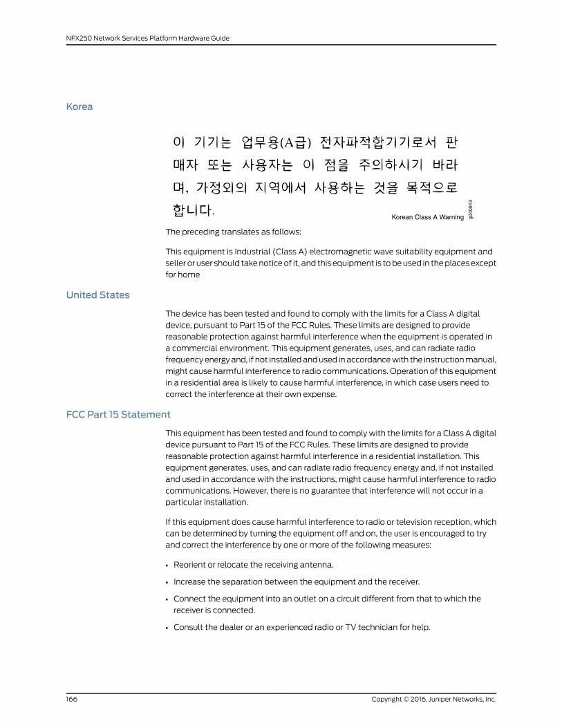
Korea
Korean Class A Warning g040
913
The preceding translates as follows:
This equipment is Industrial (Class A) electromagnetic wave suitability equipment and
seller or user should takenoticeof it, and this equipment is tobeused in theplacesexcept
for home
United States
The device has been tested and found to comply with the limits for a Class A digital
device, pursuant to Part 15 of the FCC Rules. These limits are designed to provide
reasonable protection against harmful interference when the equipment is operated in
a commercial environment. This equipment generates, uses, and can radiate radio
frequencyenergyand, if not installedandused inaccordancewith the instructionmanual,
might cause harmful interference to radio communications. Operation of this equipment
in a residential area is likely to cause harmful interference, in which case users need to
correct the interference at their own expense.
FCC Part 15 Statement
This equipment has been tested and found to comply with the limits for a Class A digital
device pursuant to Part 15 of the FCC Rules. These limits are designed to provide
reasonable protection against harmful interference in a residential installation. This
equipment generates, uses, and can radiate radio frequency energy and, if not installed
and used in accordance with the instructions, might cause harmful interference to radio
communications. However, there is no guarantee that interference will not occur in a
particular installation.
If this equipment does cause harmful interference to radio or television reception, which
can be determined by turning the equipment off and on, the user is encouraged to try
and correct the interference by one or more of the following measures:
• Reorient or relocate the receiving antenna.
• Increase the separation between the equipment and the receiver.
• Connect the equipment into an outlet on a circuit different from that to which the
receiver is connected.
• Consult the dealer or an experienced radio or TV technician for help.
Copyright © 2016, Juniper Networks, Inc.166
NFX250 Network Services Platform Hardware Guide

Nonregulatory Environmental Standards
NEBS compliance—These NFX250 devices are Network Equipment Building System(NEBS) compliant:
• NFX250-S1, NFX250-S2, and NFX250-LS1
Those devices are designed to meet the following NEBS compliance standards:
• SR-3580 NEBS Criteria Levels (Level 4 Compliance)
• GR-1089-CORE:EMCandElectricalSafety forNetworkTelecommunicationsEquipment
• GR-63-CORE: NEBS, Physical Protection
• The equipment is suitable for installation as part of the Common Bonding Network
(CBN).
• The equipment is suitable for installation in locations where the National Electrical
Code (NEC) applies.
• The battery return connection is to be treated as an Isolated DC return (DC-I), as
defined in GR-1089-CORE.
RelatedDocumentation
• Agency Approvals for NFX250 Devices on page 163
167Copyright © 2016, Juniper Networks, Inc.
Chapter 25: Agency Approvals and Compliance Statements

Copyright © 2016, Juniper Networks, Inc.168
NFX250 Network Services Platform Hardware Guide