Nfpa.11.2005 Standard for low, medium and high expansion foam
101
By Authority Of THE UNITED STATES OF AMERICA Legally Binding Document By the Authority Vested By Part 5 of the United States Code § 552(a) and Part 1 of the Code of Regulations § 51 the attached document has been duly INCORPORATED BY REFERENCE and shall be considered legally binding upon all citizens and residents of the United States of America. HEED THIS NOTICE : Criminal penalties may apply for noncompliance. Official Incorporator : THE EXECUTIVE DIRECTOR OFFICE OF THE FEDERAL REGISTER WASHINGTON, D.C. Document Name: CFR Section(s): Date of Action: e NFPA 11 (2005): Standard for Low-Expansion Foam 29 CFR 1915.507 69 FR 55706, Sept. 15, 2004; 71 60847, Oct. 17, 2006
-
Upload
alex-schoots -
Category
Engineering
-
view
951 -
download
9
Transcript of Nfpa.11.2005 Standard for low, medium and high expansion foam

By Authority OfTHE UNITED STATES OF AMERICA
Legally Binding Document
By the Authority Vested By Part 5 of the United States Code § 552(a) and Part 1 of the Code of Regulations § 51 the attached document has been duly INCORPORATED BY REFERENCE and shall be considered legally binding upon all citizens and residents of the United States of America. HEED THIS NOTICE: Criminal penalties may apply for noncompliance.
Official Incorporator:THE EXECUTIVE DIRECTOROFFICE OF THE FEDERAL REGISTERWASHINGTON, D.C.
Document Name:
CFR Section(s):
Date of Action:
eNFPA 11 (2005): Standard for Low-Expansion Foam
29 CFR 1915.507
69 FR 55706, Sept. 15, 2004; 71 60847, Oct. 17, 2006
v •
Iy
L 11 12.0 0 0 0 0 .0 '0 0 0 0 0 0 0 0 11< . ~;
-.... -...., 6
0 NFPA 11 I" (J)
is' Standard for ::J Q.
0 III =Cb ~.
Low-, Medium-, and r '0 ~ ..
0 ~
~ CD 9: HiQh-Expansion Foam c .
~ 0 ~
~' -::J Q.
~' 2005 Edition (Q ::r
0 ; 'nO .~
"'0 III ::J. CJ)
o· ::J 0 ~
0
~,
! 0 I
il ~ .
i,.II~: I g. ''--------'
I (J1 ~
h '----------------------~

\-----
IMPORTANT NOTICES AND DISCLAIMERS CONCERNING NFPA DOCUMENTS
Notice and Disclaimer of Liability Concerning the Use or NFPA Documents
NFPA codes, standards, recommended practices, and guides, of which the document contained herein is one, are developed through a consensus standards development process approved by the American National Standards Institute. This process brings together volunteers representing varied viewpoints and interests to achieve consensus on fire and other safety issues. While the NFPA administers the process and establishes rules to promote fairness in the development of consensus, it does not independently test, evaluate, or verify the accuracy of any information or the soundness of any judgments contained in its codes and standards.
The NFPA disclaims liability for any personal injury, property or other damages of any nature whatsoever, whether special, indirect, consequential or compensatory, directly or indirectly resulting from the publication, use of, or reliance on this document. The NFPA also makes no guaranty or warranty as to the accuracy or completeness of any information published herein.
In issuing and making this document available, the NFPA is not undertaking to render professional or other services for or on behalf of any person or entity. Nor is the NFPA undertaking to perform any duty owed by any person or entity to someone else. Anyone using this document should rely on his or her own independent judgment or, as appropriate, seek the advice of a competent professional in determining the exercise of reasonable care in any given circumstances.
The NFPA has no power, nor does it undertake, to police or enforce compliance with the contents of this document. Nor does the NFPA list, certify, test or inspect products, designs, or installations for compliance with this document. Any certification or other statement of compliance with the requirements of this document shall not be attributable to the NFPA and is solely the responsibility of the certifier or maker of the statement.
Important Notices and Disclaimers continued on inside back cover.
10103

Copyright © 2005, National Fire Protection Association, All Rights Reserved
NFPA11
Standard for
Low-, Medium-, and High-Expansion Foam
2005 Edition
This edition ofNFPA 11, Standard far Law-, Medium-, and High-Expansion Foam, was prepared by the Technical Committee on Foam and acted on by NFPA at its November Association Technical Meeting held November 13-17, 2004, in Miami Beach, FL. It was issued by the Standards Council on January 14, 2005, with an effective date of February 7,2005, and supersedes all previous editions.
This edition of NFPA 11 was approved as an American National Standard on February 7, 2005.
Origin and Development of NFPA 11 NFPA committee activity in this field dates from 1921, when the Committee on Manufac
turing Risks and Special Hazards prepared standards on foam as a section of the general Standard on Protection of Fire Hazards, Incident to the Use of Volatiles in Manufacturing Processes. Subsequently the standards were successively under the jurisdiction of the Committee on Manufacturing Hazards and the Committee on Special Extinguishing Systems, prior to the present committee organization. The present text supersedes the prior editions adopted in 1922, 1926, 1931, 1936, 1942, 1950, 1954, 1959, 1960, 1963, 1969, 1970, 1972, 1973, 1974, 1975, 1976, and 1978. It also supersedes the 1977 edition ofNFPA lIB.
The 1983 edition was completely rewritten to include all the material formerly contained in NFPA lIB, Standard on Synthetic and CombinedAgent Systems. The standard was revised in 1988 and again in 1994 to more clearly state the requirements and to separate mandatory requirements from advisory text.
The standard was revised for the 1998 edition to include requirements for foam systems for marine applications and to provide guidance relating to the environmental impact of foam system discharges.
The 2002 edition was revised to address mixing of foam concentrates and to clarify requirements related to foam concentrate pumps. Requirements for medium- and high-expansion foam systems have been included.
The 2005 edition reorganizes the requirements for low-, medium-, and high-expansion foam to better incorporate the requirements ofNFPA llA
11-1

11-2 LOW-, MEDIUM-, AND HIGH-EXPANSION FOAM
Technical Committee on Foam
Christopher P. Hanauska, Chair Hughes Associates, Inc., MD [SE]
Jean.Pierre Asselin, FireFlex Systems, Inc., Canada [M] v. Frank Bateman, Kidde Fire Fighting, CA [M] Gene E. Benzenberg, Alison Control Incorporated, NJ [M] W. D. Cochran, Verde Environmental, TX [M] Arthur R. Dooley,Jr., Dooley Tackaberry, Inc., TX [1M]
Rep. National Association of Fire Equipment Distributors
Robert A. Green, Public Service Electric & Gas Company, NJ [U]
Rep. Edison Electric Institute Randall Hendricksen, ChemGuard, Incorporated, TX [M] Eldon D.Jackson, The Viking Corporation, MI [M]
Rep. National Fire Sprinkler Association Kevin P. Kuntz, Marsh USA Inc., NJ [I] Eric LaVe~e, Williams Fire and Hazard Control, TX [M] Joan M. Leedy, Dyne Technologies, MN [1M] Ronald Mahlman, The RJA Group, Inc., CA [SE] Robert C. Merritt, FM Global, MA [I]
Rep. FM Global/FM Engineering & Research Edward C. Norman, Aqueous Foam Technology, Inc., PA [SE]
Randall Eberly, U.S. Coast Guard Headquarters, DC [E] (Alt. to K Wahle)
Mitchell Hubert, Ansul Incorporated/Tyco International, WI [M]
(Alt. to K Olson) William E. Janz, GE Global Asset Protection Services, IL [I]
(Alt. to L. A. Rawls) George E. Laverick, Underwriters Laboratories Inc., IL [RT]
(Alt. to K W. Zastrow)
Richard F. Murphy, Cranford, NJ [SE] (Member Emeritus)
David R. Hague, NFPA Staff Liaison
Alternates
Nonvoting
Keith Olson, Tyco Suppression Systems, WI [M] David W. Owen, ExxonMobil Corporation, VA [U]
Rep. American Petroleum Institute Michael F. Pierson, CSCAdvanced Marine, DC [SE] Fay Purvis, Vector Fire Technology, Inc., PA [SE] Niall Ramsden, Resource Protection International, England [SE] Lynn A. Rawls, GE Global Asset Protection Services, MS [I]
Rep. GE Global Asset Protection Services Tom Reser, Edwards Manufacturing, OR [M] Gaston "Gus" J. Santerre, Integrated Protection Services Inc., CA [1M]
Rep. American Fire Sprinkler Association Orville M. Slye,Jr., Loss Control Associates Inc., PA [SE] Howard L. Vandersall, Lawdon Fire Services, Inc., CA [SE] Klaus Wahle, U.S. Coast Guard, DC [E] Michel Williams, Ultramar Canada, Ltd., Canada [U]
Rep. NFPA Industrial Fire Protection Section Kenneth W. Zastrow, Underwriters Laboratories Inc., IL [RT]
Raymond Quenneville, FireFlex Systems, Inc., Canada [M]
(Alt. to j.-P. Asselin) Joseph L. Scheffey, Hughes Associates, Inc., MD [SE]
(Alt. to C. P. Hanauska) Donald H. Seaman, CSC Advanced Marine, DC [SE]
(Alt. to M. F. Pierson) Clark D. Shepard, ExxonMobil Corporation, VA [U]
(Alt. to D. W. Owen) JohnA. Toney, Dooley Tackaberry, Inc., TX [1M]
(Alt. to A. R Dooley)
This list represents the membership at the time the Committee was baUoted on the final text of this edition. Since that time, changes in the membership may have occurred. A key to classifuations is found at the back of the document.
NOTE: Membership on a committee shall not in and of itself constitute an endorsement of the Association or any document developed by the committee on which the member serves.
Committee Scope: This Committee shall have primary responsibility for documents on the installation, maintenance, and use of foam systems for fire protection, including foam hose streams.
2005 Edition
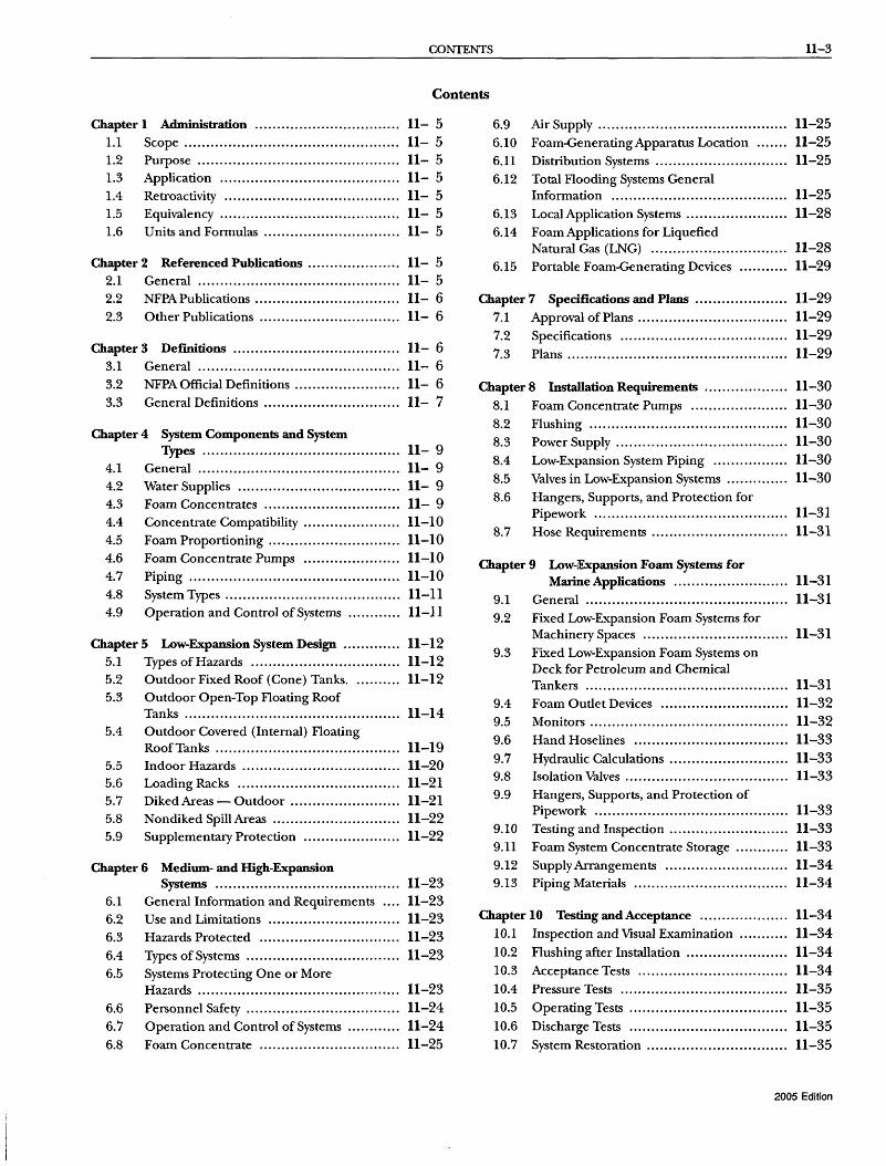
CONTENTS 11-3
Contents
Chapter 1 Administration..... ..... .... ... .......... ...... 11- 5 1.1 Scope ................................................. 11- 5 1.2 Purpose .............................................. 11- 5 1.3 Application......................................... 11- 5 1.4 Retroactivity ........................................ 11- 5 1.5 Equivalency..... ... ... ............ ... ....... ..... . .. 11- 5 1.6 Units and Formulas ............................... 11- 5
Chapter 2 Referenced Publications ..................... 11- 5 2.1 General...... ....... .... ....... .. ... ..... .. . ......... 11- 5 2.2 NFPAPublications ................................. 11- 6 2.3 Other Publications ................................ 11- 6
Chapter 3 Definitions ...................................... 11- 6 3.1 General.. ............. .. ..... ... ....... ............ .. 11- 6 3.2 NFPA Official Definitions ........................ 11- 6 3.3 General Definitions ............................... 11- 7
Chapter 4 System Components and System Types ............................................. 11- 9
4.1 General .............................................. 11- 9 4.2 Water Supplies ..................................... 11- 9 4.3 Foam Concentrates ............................... 11- 9 4.4 Concentrate Compatibility ...................... 11-10 4.5 Foam Proportioning .............................. 11-10 4.6 Foam Concentrate Pumps ...................... 11-10 4.7 Piping ................................................ 11-10 4.8 System Types ........................................ 11-11 4.9 Operation and Control of Systems ............ 11-11
Chapter 5 Low-Expansion System Design ............. 11-12 5.1 Types of Hazards .................................. 11-12 5.2 Outdoor Fixed Roof (Cone) Tanks ........... 11-12 5.3 Outdoor Open-Top Floating Roof
Tanks ................................................. 11-14 5.4 Outdoor Covered (Internal) Floating
Roof Tanks .......................................... 11-19 5.5 Indoor Hazards .................................... 11-20 5.6 Loading Racks ..................................... 11-21 5.7 Diked Areas - Outdoor ......................... 11-21 5.8 Nondiked Spill Areas ............................. 11-22 5.9 Supplementary Protection ...................... 11-22
Chapter 6 Medium- and High-Expansion Systems .... ...... ... .... ..... ....... ............. 11-23
6.1 General Information and Requirements .... 11-23 6.2 Use and Limitations .............................. 11-23 6.3 Hazards Protected ................................ 11-23 6.4 Types of Systems ................................... 11-23 6.5 Systems Protecting One or More
Hazards .............................................. 11-23 6.6 Personnel Safety ................................... 11-24 6.7 Operation and Control of Systems ............ 11-24 6.8 Foam Concentrate ................................ 11-25
6.9 Air Supply ........................................... 11-25 6.10 Foam-GeneratingApparatus Location ....... 11-25 6.11 Distribution Systems .............................. 11-25 6.12 Total Flooding Systems General
Information ........................................ 11-25 6.13 Local Application Systems ....................... 11-28 6.14 Foam Applications for Liquefied
Natural Gas (LNG) ............................... 11-28 6.15 Portable Foam-Generating Devices ........... 11-29
Chapter 7 Specifications and Plans ..................... 11-29 7.1 Approval of Plans .................................. 11-29 7.2 Specifications ...................................... 11-29 7.3 Plans .................................................. 11-29
Chapter 8 Installatiolll Requirements ................... 11-30 8.1 Foam Concentrate Pumps ...................... 11-30 8.2 Flushing ............................................. 11-30 8.3 Power Supply....................................... 11-30 8.4 Low-Expansion System Piping ... .... .......... 11-30 8.5 Valves in Low-Expansion Systems .............. 11-30 8.6 Hangers, Supports, and Protection for
Pipework ............................................ 11-31 8.7 Hose Requirements ............................... 11-31
Chapter 9 Low-lExpansion Foam Systems for Marine Applications . .... . . .... ........ ..... .. 11-31
9.1 General .............................................. 11-31 9.2 Fixed Low-Expansion Foam Systems for
Machinery Spaces ................................. 11-31 9.3 Fixed Low-Expansion Foam Systems on
Deck for Petroleum and Chemical Tankers .............................................. 11-31
9.4 Foam Outlet Devices ............................. 11-32 9.5 Monitors ............................................. 11-32 9.6 Hand Hoselines ................................... 11-33 9.7 Hydraulic Calculations ........................... 11-33 9.8 Isolation Valves ..................................... 11-33 9.9 Hangers, Supports, and Protection of
Pipework ............................................ 11-33 9.10 Testing and Inspection ........................... 11-33 9.11 Foam System Concentrate Storage ............ 11-33 9.12 Supply Arrangements ............................ 11-34 9.13 Piping Materials ................................... 11-34
Chapter 10 Testing and Acceptance ............ ... .... . 11-34 10.1 Inspection and Visual Examination ........... 11-34 10.2 Flushing after Installation ....................... 11-34 10.3 Acceptance Tests .................................. 11-34 10.4 Pressure Tests ...................................... 11-35 10.5 Operating Tests .................................... 11-35 10.6 Discharge Tests .................................... 11-35 10.7 System Restoration ................................ 11-35
2005 Edition

11-4 LOW-, MEDIUM-, AND HIGH-EXPANSION FOAM
Chapter 11 Maintenance......... ..... ... ........ .. . ....... 11-35 11.1 Periodic Inspection ............................... 11-35 11.2 Foam-Producing Equipment ................... 11-36 11.3 Piping ................................................ 11-36 11.4 Strainers ............................................. 11-36 n.5 Detection and Actuation Equipment ......... 11-36 11.6 Foam Concentrate Inspection ................. 11-36 11.7 Operating Instructions and Training ......... 11-36
Annex A Explanatory Material ........................... 11-36
Annex B Storage Tank Protection Summary .......... 11-62
Annex C Medium- and lligh-Expansion Foam ....... 11-64
2005 Edition
Annex D Tests for the Physical Properties of Low-Expansion Foam .......................... 11-64
Annex E Foam Fire-Fighting Data Sheet ............... 11-69
Annex F Foam Environmental Issues ................... 11-70
Annex G Test Method for Marine Fire-Fighting Foam Concentrates Protecting Hydrocarbon Hazards ......................... 11-74
Annex H Foam Concentrate Quality ................... 11-76
Annex I Informational References ...................... 11-80
Index ............................................................. 11-81

REFERENCED PUBLICATIONS 11-5
NFPAll
Standard for
Low-, Medium-, and High-Expansion Foam
2005 Editioll
IMPORTANT NOTE: This NFPA document is made available ff»" use subject to important notices and legal disclaimers. These notices and disclaimers appear in aU publications containing this cWcument and may be found under the heading "Important Notices and Disclaimers Concerning NFPA Documents. " They can also be obtained on request from NFPA f»" viewed at urww.nJPa.org/disclaimers.
NOTICE: An asterisk (*) following the number or letter designating a paragraph indicates that explanatory material on the paragraph can be found in Annex A
Changes other than editorial are indicated by a vertical rule beside the paragraph, table, or figure in which the change occurred. These rules are included as an aid to the user in identifying changes from the previous edition. Where one or more complete paragraphs have been deleted, the deletion is indicated by a bullet (.) between the paragraphs that remain.
A reference in brackets [ ] following a section or paragraph indicates material that has been extracted from another NFPA document. As an aid to the user, the complete title and edition of the source documents for mandatory extracts are given in Chapter 2 and those for nonmandatory extracts are given in Annex I. Editorial changes to extracted material consist of revising references to an appropriate division in this document or the inclusion of the document number with the division number when the reference is to the original document. Requests for interpretations or revisions of extracted text shall be sent to the technical committee responsible for the source document.
Information on referenced publications can be found in Chapter 2 and Annex I.
Chapter 1 Administration
1.1* Scope.
1.1.1 This standard covers the design, installation, operation, testing, and maintenance oflow-, medium-, and high-expansion foam systems for fire protection.
1.1.2 It is not the intent of this standard to specify where foam protection is required.
1.2 Purpose.
1.2.1 This standard is intended for the use and guidance of those responsible for designing, installing, testing, inspecting, approving, listing, operating, or maintaining fixed, semifixed, or portable low-, medium-, and high-expansion foam fireextinguishing systems for interior or exterior hazards.
1.2.2 Nothing in this standard is intended to restrict new technologies or alternative arrangements, provided the level of safety prescribed by the standard is not lowered.
1.3 Application. This standard is not applicable to the following types of systems:
(1) Chemical foams and systems (considered obsolete) (2) Deluge foam-water sprinkler or spray systems (See NFPA 16.)
(3) Foam-water closed-head sprinkler systems (See NFPA 16.) (4) Combined agent systems (5) Mobile foam apparatus (SeeNFPA 1901.) (6) Class A foam and systems (See NFPA 1150.)
1.4 Retroactivity. The provisions of this standard reflect a consensus of what is necessary to provide an acceptable degree of protection from the hazards addressed in this standard at the time the standard was issued.
1.4.1 Unless otherwise specified, the provisions of this standard shall not apply to facilities, equipment, structures, or installations that existed or were approved for construction or installation prior to the effective date of the standard. Where specified, the provisions of this standard shall be retroactive.
1.4.2 In those cases where the authority having jurisdiction determines that the existing situation presents an unacceptable degree of risk, the authority having jurisdiction shall be permitted to apply retroactively any portions of this standard deemed appropriate.
1.4.3 The retroactive requirements of this standard shall be permitted to be modified if their application clearly would be impractical in the judgment of the authority having jurisdiction, and only where it is clearly evident that a reasonable degree of safety is provided.
1.5 Equivalency. Nothing in this standard is intended to prevent the use of systems, methods, or devices of equivalent or superior quality, strength, fire resistance, effectiveness, durability, and safety over those prescribed by this standard.
1.5.1 Technical documentation shall be submitted to the authority having jurisdiction to demonstrate equivalency.
1.5.2 The system, method, or device shall be approved for the intended purpose by the authority having jurisdiction.
1.6 Units and Formulas. Metric units of measurement in this standard are in accordance with the modernized metric system known as the International System of Units (SI). The liter unit, which is not part of but is recognized by SI, is commonly used in international fire protection. Conversion factors for this unit are found in Table 1.6.
Table 1.6 Metric Units of Measure
Name of Unit Unit Symbol Conversion Factor
liter L 1 gal = 3.785 L liter per minute per L/min·m2 1 gpm/ft2 = 40.746
square meter L/min.m2
cubic decimeter dm3 1 gal = 3.785 dm3
pascal Pa 1 psi = 6894.757 Pa bar bar 1 psi = 0.0689 bar bar bar 1 bar = 105 Pa kilopascal kPa 1 psi = 6.895 kPa
Note: For additional conversions and information, see IEEE/ ASTM SI 10.
Chapter 2 Referenced Publications
2.1 General. The documents or portions thereof listed in this chapter are referenced within this standard and shall be considered part of the requirements of this document.
2005 Edition
11-6 LOW-, MEDIUM-, AND HIGH-EXPANSION FOAM
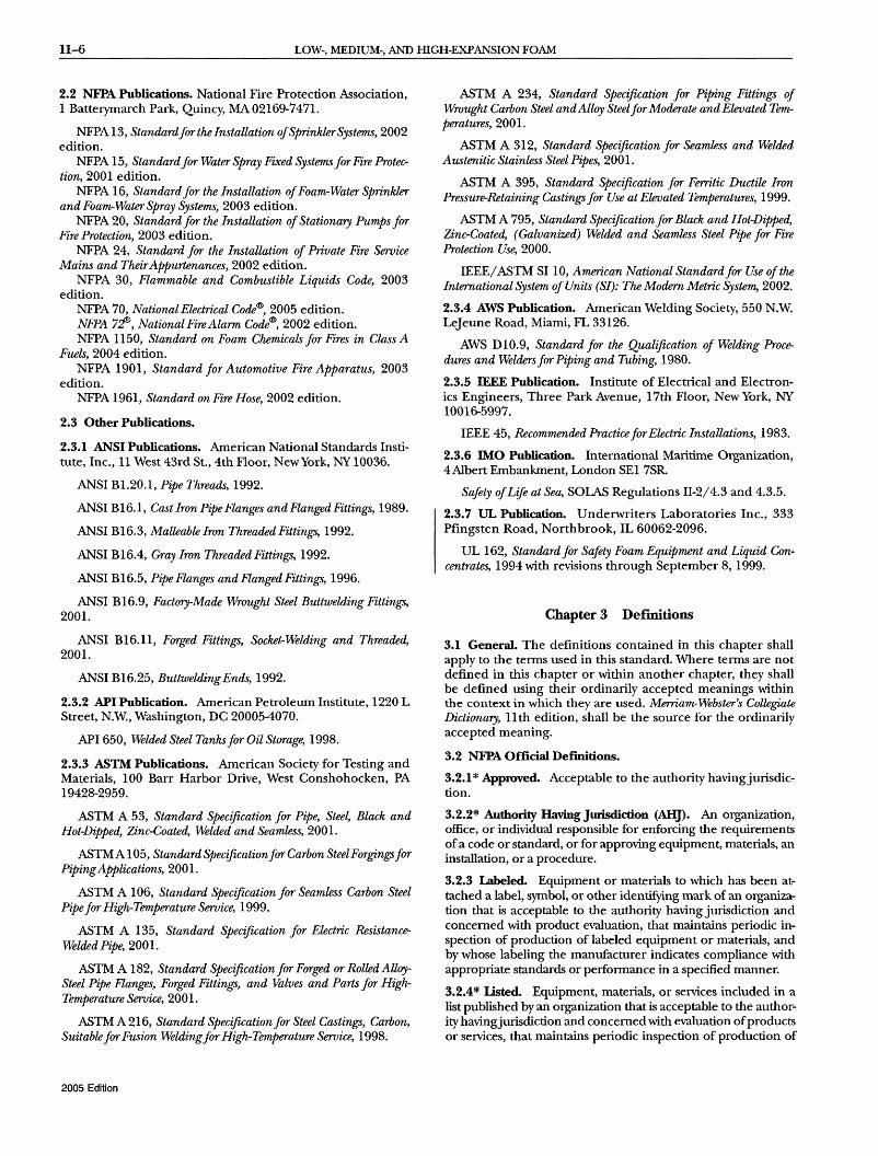
2.2 NFPA Publications. National Fire Protection Association, 1 Batterymarch Park, Quincy, MA02169-7471.
NFPA 13, Standard for the Installation of Sprinkler Systems, 2002 edition.
NFPA 15, Standard for Water Spray Fixed Systems for Fire Protection, 2001 edition.
NFPA 16, Standard for the Installation of Foam-Water Sprinkler and Foam-Water Spray Systems, 2003 edition.
NFPA 20, Standard for the Installation of Stationary Pumps for Fire Protection, 2003 edition.
NFPA 24, Standard for the Installation of Private Fire Seroice Mains and Their Appurtenances, 2002 edition.
NFPA 30, Flammable and Combustible Liquids Code, 2003 edition.
NFPA 70, National Electrical Code®, 2005 edition. NFPA 71!, National Fire Alarm Code®, 2002 edition. NFPA 1150, Standard on Foam Chemicals for Fires in Class A
Fuels, 2004 edition. NFPA 1901, Standard for Automotive Fire Apparatus, 2003
edition. NFPA 1961, Standard on Fire Hose, 2002 edition.
2.3 Other Publications.
2.3.1 ANSI Publications. American National Standards Institute, Inc., 11 West 43rd St., 4th Floor, New York, NY 10036.
ANSI B1.20.1, Pipe Threads, 1992.
ANSI BI6.1, Cast Iron Pipe Flanges and Flanged Fittings, 1989.
ANSI BI6.3, Malleable Iron Threaded Fittings, 1992.
ANSI BI6.4, Gray Iron Threaded Fittings, 1992.
ANSI BI6.5, Pipe Flanges and Flanged Fittings, 1996.
ANSI BI6.9, Factory-Made Wrought Steel Buttwelding Fittings, 2001.
ANSI BI6.11, Forged Fittings, Socket-Welding and Threaded, 2001.
ANSI BI6.25, Buttwelding Ends, 1992.
2.3.2 API Publication. American Petroleum Institute, 1220 L Street, N.W., Washington, DC 20005-4070.
API 650, Welded Steel Tanks for Oil Storage, 1998.
2.3.3 ASTM Publications. American Society for Testing and Materials, 100 Barr Harbor Drive, West Conshohocken, PA 19428-2959.
ASTM A 53, Standard Specification for Pipe, Steel, Black and Hot-Dipped, Zinc-Coated, Welded and Seamless, 2001.
ASTM A 105, Standard Specification for Carbon Steel Forgings for Piping Applications, 2001.
ASTM A 106, Standard Specification for Seamless Carbon Steel Pipe for High-Temperature Seroice, 1999.
ASTM A 135, Standard Specification for Electric ResistanceWelded Pipe, 2001.
ASTM A 182, Standard Specification for Forged or Rolled AlloySteel Pipe Flanges, Forged Fittings, and Valves and Parts for HighTemperature Seroice, 2001.
ASTM A 216, Standard Specification for Steel Castings, Carbon, Suitable for Fusion Weldingfor High-Temperature Seroice, 1998.
2005 Edition
ASTM A 234, Standard Specification for Piping Fittings of Wrought Carbon Steel and Alloy Steelfor Moderate and Elevated Temperatures, 2001.
ASTM A 312, Standard Specification for Seamless and Welded Austenitic Stainless Steel Pipes, 2001.
ASTM A 395, Standard Specification for Ferritic Ductile Iron Pressure-Retaining Castings for Use at Elevated Temperatures, 1999.
ASTM A 795, Standard Specification for Black and Hot-Dipped, Zinc-Coated, (Galvanized) Welded and Seamless Steel Pipe for Fire Protection Use, 2000.
IEEE/ ASTM SilO, American National Standardfor Use of the International System of Units (SI): The Modern Metric System, 2002.
2.3.4 AWS Publication. American Welding Society, 550 N.W. Lejeune Road, Miami, FL 33126.
AWS DI0.9, Standard for the Qualification of Welding Procedures and Welders for Piping and Tubing, 1980.
2.3.5 IEEE Publication. Institute of Electrical and Electronics Engineers, Three Park Avenue, 17th Floor, New York, NY 10016-5997.
IEEE 45, Recommended Practice for Electric Installations, 1983.
2.3.6 IMO Publication. International Maritime Organization, 4 Albert Embankment, London SEI 7SR
Safety of Life at Sea, SOLAS Regulations 11-2/4.3 and 4.3.5.
2.3.7 UL Publication. Underwriters Laboratories Inc., 333 Pfingsten Road, Northbrook, IL 60062-2096.
UL 162, Standard for Safety Foam Equipment and Liquid Concentrates, 1994 with revisions through September 8, 1999.
Chapter 3 Deimitions
3.1 General. The definitions contained in this chapter shall apply to the terms used in this standard. Where terms are not defined in this chapter or within another chapter, they shall be defined using their ordinarily accepted meanings within the context in which they are used. Merriam-Webster's Collegiate Dictionary, 11 th edition, shall be the source for the ordinarily accepted meaning.
3.2 NFPA Official Def"mitions.
3.2.1 * Approved. Acceptable to the authority havingjurisdiction.
3.2.2* Authority Having Jurisdiction (AHJ). An organization, office, or individual responsible for enforcing the requirements of a code or standard, or for approving equipment, materials, an installation, or a procedure.
3.2.3 Labeled. Equipment or materials to which has been attached a label, symbol, or other identifying mark of an organization that is acceptable to the authority having jurisdiction and concerned with product evaluation, that maintains periodic inspection of production of labeled equipment or materials, and by whose labeling the manufacturer indicates compliance with appropriate standards or performance in a specified manner.
3.2.4* Listed. Equipment, materials, or services included in a list published by an organization that is acceptable to the authority havingjurisdiction and concerned with evaluation of products or services, that maintains periodic inspection of production of

DEFlNITIONS 11-7
listed equipment or materials or periodic evaluation of services, and whose listing states that either the equipment, material, or service meets appropriate designated standards or has been tested and found suitable for a specified purpose.
3.2.5 Shall. Indicates a mandatory requirement.
3.2.6 Should. Indicates a recommendation or that which is advised but not required.
3.2.7 Standard. A document, the main text of which contains only mandatory provisions using the word "shall" to indicate requirements and which is in a fonn generally suitable for mandatory reference by another standard or code or for adoption into law. Nonmandatory provisions shall be located in an appendix or annex, footnote, or fine-print note and are not to be considered a part of the requirements of a standard.
3.3 General Definitions.
3.3.1 Combustible Liquid. A liquid that has a closed-cup flash point at or above 37.8°C (100°F). [30,2003]
3.3.1.1 Combustible Liquid Classification.
3.3.1.1.1 Combustible Liquid Class II. Any liquid that has a flash point at or above 37.8°C (lOO°F) and below 60°C (140°F). [30,2003]
3.3.1.1.2 Combustible Liquid Class IIIA. Any liquid that has a flash point at or above 60°C (140°F), but below 93°C (200°F). [30,2003]
3.3.1.1.3 Combustible Liquid Class IHB. Any liquid that has a flash point at or above 93°C (200°F). [30, 2003]
3.3.2* Concentration. The percent of foam concentrate contained in a foam solution.
3.3.3 Coupled Water-Motor Pump. A correctly designed positive displacement pump in the water supply line coupled to a second, smaller, positive displacement foam concentrate pump to provide proportioning.
3.3.4 Discharge Device. A device designed to discharge water or foam-water solution in a predetennined, fixed, or adjustable pattern. Examples include, but are not limited to, sprinklers, spray nozzles, and hose nozzles.
3.3.4.1 Air-Aspirating Discharge Devices. Devices specially designed to aspirate and mix air into the foam solution to generate foam, followed by foam discharge in a specific design pattern.
3.3.4.2* N~Air-Aspirating Discharge Devices. Devices designed to provide a specific water discharge pattern.
3.3.5 Discharge Oudet.
3.3.5.1 Fixed Foam Discharge Outlet. A device pennanently attached to a tank, dike, or other containment structure, designed to introduce foam.
3.3.5.2 TYPe I Discharge Outlet. An approved discharge outlet that conducts and delivers foam gently onto the liquid surface without submergence of the foam or agitation of the surface.
3.3.5.3 TYPe II Discharge Outlet. An approved discharge outlet that does not deliver foam gently onto the liquid surface but is designed to lessen submergence of the foam and agitation of the surface.
3.3.6* Eductor (Inductor). A device that uses the Venturi principle to introduce a proportionate quantity of foam concentrate into a water stream; the pressure at the throat is below atmospheric pressure and will draw in liquid from atmospheric storage.
3.3.6.1 * In-Line Eductor. A Venturi-type proportioning device that meters foam concentrate at a fixed or variable concentration into the water stream at a point between the water source and a nozzle or other discharge device.
3.3.7 Expansion. The ratio of final foam volume to original foam solution volume.
3.3.8 Fire.
3.3.8.1 Class A Fire in ordinary combustible materials, such as wood, cloth, paper, rubber, and many-plastics.
3.3.8.2 Class B. Fires in flammable liquids, combustible liquids, petroleum greases, tars, oils, oil-based paints, solvents, lacquers, alcohols, and flammable gases.
3.3.9 Flammable Liquid. A liquid that has a closed-cup flash point that is below 37.8°C (lOO°F) and a maximum vapor pressure of 2068 mm Hg (40 psia) at 37.8°C (lOO°F). [30,2003]
3.3.9.1 Flammable Liquid Classification.
3.3.9.1.1 Flammable Liquid Class I. Any liquid that has a closed-cup flash point below 37.8°C (lOO°F) and a Reid vapor pressure not exceeding 2068.6 mm Hg (40 psia) at 37.8°C (lOO°F). [30,2003]
3.3.9.1.2 Flammable Liquid Class IA. Any liquid that has a flash point below 22.8°C (73°F) and a boiling point below 37.8°C (lOO°F). [30,2003]
3.3.9.1.3 Flammable Liquid Class lB. Any liquid that has a flash point below 22.8°C (73°F) and a boiling point at or above 37.8°C (lOO°F). [30,2003]
3.3.9.1.4 Flammable Liquid Class IC. Any liquid that has a flash point at or above 22.8°C (73°F) but below 37.8°C (100°F). [30,2003]
3.3.10* Foam. Astable aggregation of small bubbles oflower density than oil or water that exhibits a tenacity for covering horizontal surfaces.
3.3.11 Foam Chamber. See 3.3.5.1, Fixed Foam Discharge Outlet.
3.3.12* Foam Concentrate. A concentrated liquid foaming agent as received from the manufacturer.
3.3.12.1 * Alcohol-Resistant Foam Concentrate. Aconcentrate used for fighting fires on water-soluble materials and other fuels destructive to regular, AFFF, or FFFP foams, as well as for fires involving hydrocarbons.
3.3.12.2* Aqueous Fil~Forming Foam Concentrate (AFFF). A concentrate based on fluorinated surfactants plus foam stabilizers and usually diluted with water to a 1 percent, 3 percent, or 6 percent solution.
3.3.12.3* Fluoroprotein Foam Concentrate. A concentrate very similar to protein-foam concentrate but with a synthetic fluorinated surfactant additive.
3.3.12.3.1 * Fil~Fonning Fluoroprotein Foam Concentrate (FFFP). A concentrate that uses fluorinated surfactants to produce a fluid aqueous film for suppressing hydrocarbon fuel vapors.
2005 Edition

11-8 LOW-, MEDIUM-, AND HIGH-EXPANSION FOAM
3.3.12.4* Mediu~ and HiglvExpansion Foam Concentrate. A concentrate, usually derived from hydrocarbon surfactants, used in specially designed equipment to produce foams having foam-to-solution volume ratios of 20:1 to approximately 1000:1.
3.3.12.5* Protein Foam Concentrate. Concentrate consisting primarily of products from a protein hydrolysate, plus stabilizing additives and inhibitors to protect against freezing, to prevent corrosion of equipment and containers, to resist bacterial decomposition, to control viscosity, and to otherwise ensure readiness for use under emergency conditions.
3.3.12.6 Synthetic Foam Concentrate. Concentrate based on foaming agents other than hydrolyzed proteins and including aqueous film-forming foam (AFFF) concentrates, mediumand high-expansion foam concentrates, and other synthetic foam concentrates.
3.3.12.6.1 * Other Synthetic Foam Concentrate. Aconcentrate based on hydrocarbon surface active agents and listed as a wetting agent, foaming agent, or both.
3.3.13 Foam Concentrate Type. Aclassification of a foam concentrate that includes the chemical composition as defined under foam concentrate (see 3.3.12), including the use percentage, the minimum usable temperature, and the fuels on which the concentrate is effective.
3.3.14 Foam Generators.
3.3.14.1 Foam Generators - Aspirator TYPe. Foam generators, fixed or portable, in whichjet streams of foam solution aspirate sufficient amounts of air that is then entrained on the screens to produce foam, and which usually produce foam with expansion ratios of not more than 250: l.
3.3.14.2* Foam Generators - Blower TYPe. Foam generators, fixed or portable, in which the foam solution is discharged as a spray onto screens through which an airstream developed by a fan or blower is passing.
3.3.15 Foam Injection.
3.3.15.1 Semisubsurface Foam Injection. Discharge of foam at the liquid surface within a storage tank from a floating hose that rises from a piped container near the tank bottom.
3.3.15.2 Subsurface Foam Injection. Discharge of foam into a storage tank from an outlet near the tank bottom.
3.3.16* Foam Solution. A homogeneous mixture of water and foam concentrate in the correct proportions.
3.3.16.1 Premixed Foam Solution. Solution produced by introducing a measured amount of foam concentrate into a given amount of water in a storage tank.
3.3.17 Foam System Types.
3.3.17.1 Fixed System. A complete installation in which foam is piped from a central foam station, discharging through fixed delivery outlets to the hazard to be protected with permanently installed pumps where required.
3.3.17.2* Mobile System. Any type of foam-producing unit that is mounted on wheels and that is self-propelled or towed by a vehicle and can be connected to a water supply or can utilize a premixed foam solution.
3.3.17.3 Portable System. Foam-producing equipment, materials, hose, and so forth, that are transported by hand.
2005 Edition
3.3.17.4* Semifixed System. A system in which the hazard is equipped with fixed discharge outlets connected to piping that terminates at a safe distance.
3.3.18* Foam-Generating Methods. Methods of generation of air foam including hose stream, foam nozzle, and medium- and high-expansion generators, foam maker, pressure foam maker (high back pressure or forcing type), or foam monitor stream.
3.3.19* Handline. A hose and nozzle that can be held and directed by hand.
3.3.20 Monitor.
3.3.20.1 * Fixed Moniror (Cannon). A device that delivers a large foam stream and is mounted on a stationary support that either is elevated or is at grade.
3.3.20.2 Pmtable Moniror (Cannon). A device that delivers a foam monitor stream and is mounted on a movable support or wheels so it can be transported to the fire scene.
3.3.21 Nozzle.
3.3.21.1 * Foam Nozzle or Fixed Foam Maker. A specially designed hoseline nozzle or fixed foam maker designed to aspirate air that is connected to a supply of foam solution.
3.3.21.2* SelfEducting Nozzle. A device that incorporates a venturi to draw foam concentrate through a short length of pipe and/or flexible tubing connected to the foam supply.
3.3.22* Pressure Foam Maker (High Back-Pressure or Forcing Type). A foam maker utilizing the Venturi principle for aspirating air into a stream of foam solution forms foam under pressure.
3.3.23* Pressure Proportioning Tank. A foam concentrate tank with no bladder that uses water flow through an orifice to displace the foam concentrate in the tank with water to add foam concentrate through an orifice into a water line at a specified rate. This device is only suitable for foams having a specific gravity of at least 1.15.
3.3.24 Balanced Pressure Bladder Tank. A foam concentrate tank fitted with an internal bladder which uses water flow through a modified venturi type proportioner to control the foam concentrate injection rate by displacing the foam concentrate within the bladder with water outside the bladder.
3.3.25 Proportioning. The continuous introduction of foam concentrate at the recommended ratio into the water stream to form foam solution.
3.3.25.1 * Balanced Pressure Pump-TYPe Proportioning. A foam proportioning system that utilizes a foam pump and valve(s) to balance foam and water pressures at a modified venturi-type proportioner located in the foam solution delivery piping; a foam concentrate metering orifice is fitted in the foam inlet section of the proportioner.
3.3.25.1.1 * In-Line Balanced Pressure Proportioning. A foam proportioning system utilizing a foam concentrate pump at all design flow rates, the constant pressure of which is greater than the maximum water pressure under all operating conditions.
3.3.25.2* Direct Injection Variable Pump Output Proportioning. A direct injection proportioning system that utilizes flowmeters for foam concentrate and water in conjunction with a variable output foam pump control system.

SYSTEM COMPONENTS AND SYSTEM 'TYPES 11-9
3.3.26 Proportioning Methods for Foam Systems. The methods of proportioning used to create the correct solution of water and foam liquid concentrate.
3.3.27* Pump Proportioner (Around-the-Pwnp Proportioner). A system that uses a venturi eductor installed in a bypass line
between the discharge and suction side of a water pump and suitable variable or fIxed orifIces to induct foam concentrate from a tank or container into the pump suction line.
3.3.28 Stream.
3.3.28.1 Foam Hose Stream. Afoam stream from a handline.
3.3.28.2 Foam Monitor Stream. A large capacity foam stream from a nozzle that is supported in position and can be directed by one person.
Chapter 4 System Components and System Types
4.1 * General. This chapter shall provide requirements for the correct use of foam system components.
4.1.1 All components shall be listed for their intended use.
4.1.2 Where listings for components do not exist, components shall be approved.
4.2 Water Supplies.
4.2.1 Water Supplies, Including Premix Solution.
4.2.1.1 <!uali~.
4.2.1.1.1 The water supply to foam systems shall be permitted to be hard or soft, fresh or salt, but shall be of a quality such that adverse effects on foam formation or foam stability do not occur.
4.2.1.1.2 No corrosion inhibitors, emulsion breaking chemicals, or any other additives shall be present without prior consultation with the foam concentrate supplier.
4.2.1.2* <!uanti~. The water supply shall be of a quantity to supply all the devices that shall be permitted to be used simultaneously for the specifIed time.
4.2.1.2.1 This quantity shall include not only the volume required for the foam apparatus but also water that can be used in other fire-fighting operations, in addition to the normal plant requirements.
4.2.1.2.2 Premixed solution-type systems shall not be required to be provided with a continuous water supply.
4.2.1.3 Pressure. The pressure available at the inlet to the foam system (e.g., foam generator, air foam maker) under required flow conditions shall be at least the minimum pressure for which the system has been designed.
4.2.1.4* Temperature. Optimum foam production shall be obtained by using water at temperatures between 4°C (40°F) and 37.8°C (lOO°F).
4.2.1.5 Design. The water system shall be designed and installed in accordance with NFPA 24.
4.2.1.5.1 Strainers shall be provided where solids of a size large enough to obstruct openings or damage equipment are present.
4.2.1.5.2 Hydrants furnishing the water supply for foam equipment shall be provided in the required number.
4.2.1.5.3 Hydrants shall be located as required by the authority having jurisdiction (AHJ).
4.2.1.6 Storage. Water supply or premixed solution shall be protected against freezing in climates where freezing temperatures are expected.
4.2.2 Water and Foam Concentrate Pumps.
4.2.2.1 When water or foam concentrate pumps are required for automatic foam system operation, they shall be designed and installed in accordance with NFPA 20.
4.2.2.2 Controllers in accordance with NFPA 20 shall not be required for manual systems.
4.3 Foam Concentrates.
4.3.1 Types of Foam Concentrate.
4.3.1.1 Foam concentrate shall be listed.
4.3.1.2* The concentrate used in a foam system shall be listed for use on the specific flammable or combustible liquid to be protected.
4.3.1.3 The limitations of the listing and the manufacturers' specifIcations shall be followed.
4.3.1.4 Foam concentrates for protection of hydrocarbon fuels shall be one of the following types:
(1) Protein (2) Fluoroprotein (3) Aqueous film-forming foam (AFFF) (4) Film-forming fluoroprotein (FFFP) (5) Alcohol-resistant (6) High-expansion (7) Medium-expansion (8) Others listed for this purpose
4.3.1.5 Water-miscible and polar flammable or combustible liquids shall be protected by alcohol-resistant concentrates listed for this purpose.
4.3.2 Concentrate Storage.
4.3.2.1 Storage Facilities.
4.3.2.1.1 Foam concentrates and equipment shall be stored in a location not exposed to the hazard they protect.
4.3.2.1.2 If housed, foam concentrates and equipment shall be in a noncombustible structure.
4.3.2.1.3 For outdoor nonautomatic systems, the AHJ shall be permitted to approve the storage offoam concentrate in a location off premises where these supplies are available at all times.
4.3.2.1.4 Loading and transportation facilities for foam concentrates shall be provided.
4.3.2.1.5 Off-premises supplies shall be of the type required for use in the systems of the given installation.
4.3.2.1.6 At the time of a fire, these off.premises supplies shall be accumulated in the required quantities, before the equipment is placed in operation, to ensure uninterrupted foam production at the design rate for the required period of time.
4.3.2.2* <!uanti~. The amount of concentrate shall be at least sufficient for the largest single hazard protected or group of hazards that are to be protected simultaneously.
2005 Edition

11-10 LOW-, MEDIUM-, AND HIGH-EXPANSION FOAM
4.3.2.3 Foam Concentrate Storage Tanks.
4.3.2.3.1 Bulk liquid storage tanks shall be fabricated from or be lined with materials compatible with the concentrate.
4.3.2.3.2 The storage tank shall be designed to minimize evaporation of foam concentrate.
4.3.2.4 Storage Conditions.
4.3.2.4.1 * In order to ensure the correct operation of any foamproducing system, the chemical and physical characteristics of the materials comprising the system shall be taken into consideration in design.
4.3.2.4.2* Foam concentrates shall be stored within the listed temperature limitations.
4.3.2.4.3 Markings shall be provided on storage vessels to identify the type of concentrate and its intended concentration in solution.
4.3.2.5 Foam Concentrate Supply.
4.3.2.5.1 Foam Concentrate Consumption Rates. The consumption rates shall be based on the percentage concentrate used in the system design (e.g., 3 percent or 6 percent or other, if so listed or approved by the AH]) .
4.3.2.5.2 Reserve Supply of Foam Concentrate.
4.3.2.5.2.1 There shall be a reseIVe supply of foam concentrate to meet design requirements in order to put the system back into service after operation.
4.3.2.5.2.2 The reseIVe supply shall be in separate tanks or compartments, in drums or cans on the premises, or available from an approved outside source within 24 hours.
4.3.2.6 Auxiliary Supplies. Other equipment necessary to recommission the system, such as bottles of nitrogen or carbon dioxide for premix systems, also shall be available.
4.4 Concentrate Compatibility.
4.4.1 Compatibility of Foam Concentrates.
4.4.1.1 * Different types of foam concentrates shall not be mixed for storage.
4.4.1.2 Different brands of the same type of concentrate shall not be mixed unless data are provided by the manufacturer to and accepted by the AH] to prove that they are compatible.
4.4.1.3 Low-expansion foams generated separately from protein, fluoroprotein, FFFP, andAFFF concentrates shall be permitted to be applied to a fire in sequence or simultaneously.
4.4.2* Foam Compatibility with Dry Chemical Agents.
4.4.2.1 The manufacturers of the dry chemical and foam concentrate to be used in the system shall confirm that their products are mutually compatible.
4.4.2.2 Where used, limitations imposed on either of the agents alone shall be applied.
4.5 Foam Proportioning. The method of foam proportioning shall conform to one of the following:
(1) Self-educting nozzle (2) In-line eductor (3) Pressure proportioners (with or without bladder) (4) Around-the-pump proportioners (5) Direct injection variable output foam pump system
2005 Edition
(6) Coupled-water motor pump (7) Balanced pressure pump-type proportioners
4.6* Foam Concentrate Pumps.
4.6.1 The design and materials of construction for foam concentrate pumps shall be in accordance with NFPA 20.
4.6.2 Special attention shall be paid to the type of seal or packing used. Seals or packing used shall be compatible with the foam concentrate.
4.6.3 Foam concentrate pumps shall have adequate capacities to meet the maximum system demand.
4.6.4 To ensure positive injection of concentrates, the discharge pressure ratings of pumps at the design discharge capacity shall be in excess of the maximum water pressure available under any condition at the point of concentration injection.
4.7 Piping.
4.7.1 Pipe Materials. Pipe within the hazard area shall be of steel or other alloy rated for the pressure and temperature involved.
4.7.1.1 Steel pipe shall not be less than standard weight (Schedule 40 through nominal 12 in. diameter).
4.7.1.2 Steel pipe shall conform to one of the following standards:
(1) ASTMA 135 (2) ASTMA53 (3) ASTMA 795
4.7.1.3 Pipe outside the hazard area shall conform to the materials allowed by NFPA 24.
4.7.1.4 Where exposed to corrosive influences, the piping shall be corrosion resistant or protected against corrosion.
4.7.1.5 Ugh tweigh t pipe [Schedule lOin nominal sizes through 5 in.; 3.40 mm (0.134 in.) wall thickness for 6 in.; and 4.78 mm (0.188 in.) wall thickness for 8 in. and 10 in.] shall be permitted to be used in areas where fire exposure is improbable.
4.7.1.6 Selection of pipe wall thickness shall anticipate internal pressure, internal and external pipe wall corrosion, and mechanical bending requirements.
4.7.2 Foam System Piping.
4.7.2.1 * Galvanized pipe shall be used for noncorrosive atmospheres.
4.7.2.2 Pipe carrying foam concentrate shall not be galvanized.
4.7.2.3 Piping in constant contact with foam concentrates shall be constructed of material compatible with and not affected by the concentrate.
4.7.2.4 Piping in constant contact with foam concentrate shall not have a detrimental effect on the foam concentrate.
4.7.2.5 For the purpose of computing friction loss in foam solution piping, the following C-values shall be used for the Hazen-Williams formula:
(1) Black steel or unlined cast iron pipe - 100 (2) Galvanized steel pipe - 120 (3) Asbestos-cement or cement-lined cast iron pipe - 140
SYSTEM COMPONENTS AND SYSTEM TI'PES 11-11
4.7.3 Fittings.
4.7.3.1 All pipe fittings shall be in accordance with one of the following:
(1) ANSI B16.1 (2) ANSI B16.3 (3) ANSI B16.4 (4) ANSI B16.5 (5) ANSI B16.9 (6) ANSI BI6.11 (7) ANSI B16.25 (8) ASTMA234
4.7.3.2 Fittings shall not be less than standard weight.
4.7.3.3 Cast-iron fittings shall not be used where dry sections of piping are exposed to possible fire or where fittings are subject to stress in self-supporting systems.
4.7.3.4 Rubber or elastomeric-gasketed fittings shall not be used in fire-exposed areas unless the foam system is automatically actuated.
4.7.3.5* Galvanized fittings shall be used for noncorrosive ,atmospheres.
4.7.3.6 Fittings carrying foam concentrate shall not be galvanized.
4.7.4 Joining of Pipes and Fittings.
4.7.4.1 Pipe threading shall be in conformance with ANSI B1.20.1.
4.7.4.2 Dimensions of cut- and roll-grooves and outside diameters of piping materials shall conform to the manufacturers' recommendations and the approval laboratories' certifications.
4.7.4.3* Welding practices shall conform to the requirements ofAWS DI0.9.
4.7.4.3.1 Precautions shall be taken to ensure that the openings are fully cut out and that no obstructions remain in the waterway.
4.7.4.3.2 Precautions shall be taken to ensure that no galvanic corrosion occurs between piping and fittings.
4.7.5 Strainers.
4.7.5.1 Strainers shall be provided where solids ofa size large enough to obstruct openings or damage equipment are present.
4.7.5.2 The ratio of the strainer's open basket area to its inlet pipe area shall be at least 10: 1.
4.7.5.2.1 The net open area of the strainer shall be at least four times the area of the suction piping.
4.7.5.2.2 Strainer mesh size shall be in accordance with the pump manufacturer's recommendations.
4.7.6* Valves.
4.7.6.1 All valves for water and foam solution lines shall be of the indicator type, such as OS&Y or post indicator.
4.7.6.2 Automatic valves for foam concentrate lines shall be listed for this service.
4.7.6.3 Valve specifications for water use shall be permitted outside the hazard or diked area.
4.7.6.4 Inside the hazard or diked area, automatic control valves and shutoff valves shall be of steel or other alloy capable of withstanding exposure to fire temperatures.
4.7.6.5 All valves required for automatic foam systems shall be supervised in their normal operating position by one of the following methods:
(1) Electrical, in accordance with NFPA 72 (2) Locked (3) Sealed
4.8 System 1YPes. The following four types of systems shall be permitted:
(1) Fixed (2) SemifIxed (3) Mobile (4) Portable
4.9 Operation and Control of Systems.
4.9.1 Methods of Actuation.
4.9.1.1 Systems shall be permitted to be actuated automatically or manually.
4.9.1.2 All systems shall have provisions for manual actuation.
4.9.2 Automatically Actuated Systems.
4.9.2.1 An automatic system shall be activated by automatic detection equipment.
4.9.2.2 Operation shall be controlled by listed or approved mechanical, electrical, hydraulic, or pneumatic means.
4.9.2.3 Where operation is automatic, a reliable source of energy shall be used.
4.9.2.4 The need for an alternate power supply shall be determined by the authority having jurisdiction.
4.9.2.5* Automatic Detection Equipment.
4.9.2.5.1 Automatic detection equipment - whether pneumatic, hydraulic, or electric - shall be provided with supervision arranged so that failure of equipment or loss of supervising air pressure or loss of electric energy results in positive notification of the abnormal condition.
4.9.2.5.2 Small systems for localized hazards shall be permitted to be unsupervised, subject to approval of the AHJ.
4.9.2.6* Electric automatic detection equipment and any auxiliary electric equipment, if in hazardous areas, shall be designed expressly for use in such areas.
4.9.2.7 In some cases, it shall be permitted to arrange the system to shut off automatically after a predetermined operating time.
4.9.2.7.1 Automatic shutdown shall be subject to the approval of the ARJ.
4.9.2.7.2 Where automatic shutdown is required, an alarm condition shall remain until manually reset.
4.9.2.8 Detection System.
4.9.2.8.1 The detection system shall activate a local alarm as well as an alarm at a constantly attended location.
4.9.2.8.2 Detection systems alarms also shall be actuated when the system is operated manually.
2005 Edition

11-12 LOW-, MEDIUM-, AND HIGH-EXPANSION FOAM
4.9.3 Manually Actuated Systems.
4.9.3.1 Controls for manually actuated systems shall be located in a place removed from the hazard zone to permit them to be operated in an emergency, yet close enough to ensure operator knowledge of fire conditions.
4.9.3.2 The location and purposes of the controls shall be indicated and shall be related to the operating instructions.
4.9.4 Equipment.
4.9.4.1 All operating devices shall be designed for the service conditions they encounter.
4.9.4.2 Operating devices shall not be rendered inoperative, or be susceptible to inadvertent operation, by environmental factors such as high or low temperature, atmospheric humidity or pollution, or marine conditions.
4.9.4.3 Operating device systems shall have means for manual actuation.
Chapter 5 Low-Expansion System Design
5.1 * 1YPes of Hazards. This chapter shall cover design information for the use of low-expansion foam to protect outdoor storage tanks, interior flammable liquid hazards, loading racks, diked areas, and nondiked spill areas.
5.2 Outdoor Fixed Roof (Cone) Tanks. The following methods for protecting exterior fixed-roof tanks shall be included within this section:
(l) Foam monitors and handlines (2) Surface application with fixed foam discharge oudets (3) Subsurface application (4) Semisubsurface injection methods
This list of methods shall not be considered to be in any order of preference.
5.2.1 Supplementary Protection. In addition to the primary means of protection, supplementary protection shall be provided in accordance with the requirements found in Section 5.9.
5.2.2 Basis of Design. System design shall be based on protecting the tank requiring the largest foam solution flow, including supplementary hose streams.
5.2.3* Limitations. Fixed oudets shall not be used to protect horizontal or pressure tanks.
5.2.4 Design Criteria for Foam Monitors and Handlines.
5.2.4.1 Limitations.
5.2.4.1.1 Monitor nozzles shall not be considered as the primary means of protection for fixed-roof tanks over 18 m (60 ft) in diameter.
5.2.4.1.2 Foam handlines shall not be permitted to be used as the primary means of protection for fixed-roof tanks over 9 m (30 ft) in diameter or those over 6 m (20 ft) in height.
5.2.4.2 Foam Application Rates.
5.2.4.2.1 * To determine actual solution flow requirements, consideration shall be given to potential foam losses from wind, and other factors shall be included in the calculations.
5.2.4.2.2* The design parameters for the use of monitors and handline nozzles to protect tanks containing hydrocarbons shall be in accordance with Table 5.2.4.2.2.
5.2.4.3* Tanks Containing Flammable and Combustible liquids Requiring Alcohol-Resistant Foams.
5.2.4.3.1 * Water-soluble and certain flammable and combustible liquids and polar solvents that are destructive to regular (nonalcohol-resistant) foams shall use alcohol-resistant foams.
5.2.4.3.2* For liquids of a depth greater than 25.4 mm (1 in.), monitor and foam hose streams shall be limited for use with special alcohol-resistant foams listed and/or approved, for the purpose.
Table 5.2.4.2.2 Foam Handline and Monitor Protection for Fixed-Roof Storage Tanks Containing Hydrocarbons
Hydrocarbon Type
Flash point between 37.8°C and 60°C (lOO°F and 140°F)
Flash point below 37.8°C (lOO°F) or liquids heated above their flash points
Crude petroleum
Notes:
Minimum Application Rate
gpm/fr
6.5 0.16
6.5 0.16
6.5 0.16
Minimum Discharge Time
(min)
50
65
65
(1) Included in this table are gasohols and unleaded gasolines containing no more than 10 percent oxygenated additives by volume. Where oxygenated additives content exceeds 10 percent by volume, protection is normally in accordance with 5.2.4.3. Certain nonalcohol-resistant foams might be suitable for use with fuels containing oxygenated additives of more than 10 percent by volume. The manufacturer should be consulted for specific listings or approvals.
(2) Flammable liquids having a boiling point of less than 37.8°C (100°F) might require higher rates of application. Suitable rates of application should be determined by test. Flammable liquids with a wide range of boiling points might develop a heat layer after prolonged burning and then can require application rates of 8.1 L/min . m2 (0.2 gpm/ft2) or more.
(3) Care should be taken in applying portable foam streams to high-viscosity materials heated above 93.3°C (200°F). Good judgment should be used in applying foam to tanks containing hot oils, burning asphalts, or burning liquids that have a boiling point above the boiling point of water. Although the comparatively low water content of foams can beneficially cool such fuels at a slow rate, it can also cause violent frothing and "slop-over" of the tank's contents.
2005 Edition
LOW-EXPANSION SYSTEM DESIGN 11-13
5.2.4.3.3 In all cases, the manufacturer of the foam concentrate and the foam-making equipment shall be consulted as to limitations and for recommendations based on listings or specific fire tests.
5.2.4.4 Design Parameters. Where monitors and handline nozzles are used to protect tanks containing flammable and combustible liquids requiring alcohol-resistant foams, the operation time shall be 65 minutes at listed application rates, unless the foam manufacturer has established, by fire test, that a shorter time can be permitted.
5.2.5 Design Criteria Surface Application with Fixed Foam Discharge Outlets.
5.2.5.1 * Fixed Foam Discharge Outlets.
5.2.5.1.1 For the protection ofa flammable liquid contained in a vertical fixed-roof (cone) atmospheric storage tank, discharge outlets shall be attached to the tank.
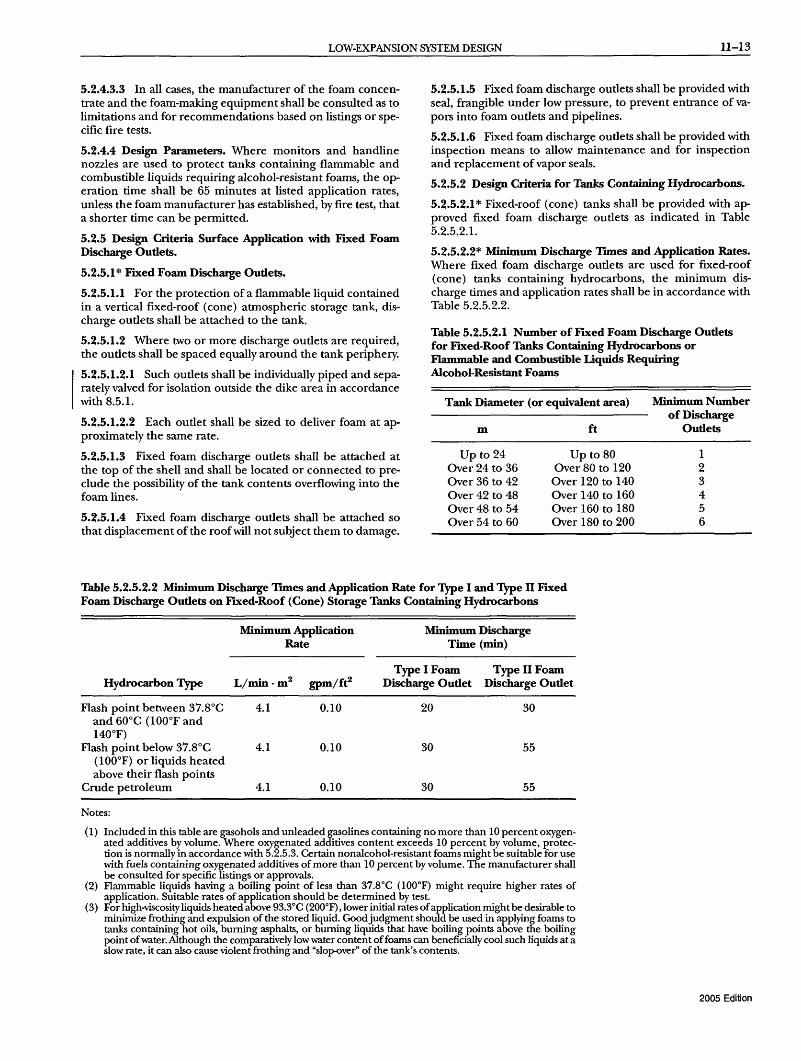
5.2.5.1.2 Where two or more discharge outlets are required, the outlets shall be spaced equally around the tank periphery.
5.2.5.1.2.1 Such outlets shall be individually piped and separately valved for isolation outside the dike area in accordance with 8.5.1.
5.2.5.1.2.2 Each outlet shall be sized to deliver foam at approximately the same rate.
5.2.5.1.3 Fixed foam discharge outlets shall be attached at the top of the shell and shall be located or connected to preclude the possibility of the tank contents overflowing into the foam lines.
5.2.5.1.4 Fixed foam discharge outlets shall be attached so that displacement of the roofwill not subject them to damage.
5.2.5.1.5 Fixed foam discharge outlets shall be provided with seal, frangible under low pressure, to prevent entrance of vapors into foam outlets and pipelines.
5.2.5.1.6 Fixed foam discharge outlets shall be provided with inspection means to allow maintenance and for inspection and replacement of vapor seals.
5.2.5.2 Design Criteria for Tanks Containing Hydrocarbons.
5.2.5.2.1 * Fixed-roof (cone) tanks shall be provided with approved fixed foam discharge outlets as indicated in Table 5.2.5.2.l.
5.2.5.2.2* Minimum Discharge TIlDes and Application Rates. Where fixed foam discharge outlets are used for fixed-roof (cone) tanks containing hydrocarbons, the minimum discharge times and application rates shall be in accordance with llable 5.2.5.2.2.
Table 5.2.5.2.1 Number of FIxed Foam Discharge Outlets for FIXed-Roof Tanks Containing Hydrocarbons or Flammable and Combustible Liquids Requiring Alcohol-Resistant Foams
Tank Diameter (or equivalent area)
m
Up to 24 Over 24 to 36 Over 36 to 42 Over 42 to 48 Over 48 to 54 Over 54 to 60
ft
Up to 80 Over 80 to 120 Over 120 to 140 Over 140 to 160 Over 160 to 180 Over 180 to 200
Minimum Number of Discharge
Outlets
1 2 3 4 5 6
Table 5.2.5.2.2 Minimum Discharge TIlDes and Application Rate for Type I and Type IT Fixed Foam Discharge Outlets on Fixed-Roof (Cone) Storage Tanks Containing Hydrocarbons
Minimum Application Minimum Discharge Rate Time (min)
L/min.m2 gpm/ft2 Type I Foam Type II Foam
Hydrocarbon Type Discharge Outlet Discharge Outlet
Flash point between 37.8°C 4.1 0.10 20 30 and 60°C (lOO°F and 140°F)
Flash point below 37.8°C 4.1 0.10 30 55 (100°F) or liquids heated above their flash points
Crude petroleum 4.1 0.10 30 55
Notes:
(1) Included in this table are gasohols and unleaded gasolines containing no more than 10 percent oxygenated additives by volume. Where oxygenated additives content exceeds 10 percent by volume, protection is normally in accordance with 5.2.5.3. Certain nonalcohol-resistant foams might be suitable for use with fuels containing oxygenated additives of more than 10 percent by volume. The manufacturer shall be consulted for specific listings or approvals.
(2) Flammable liquids having a boiling point of less than 37.8°C (lOO°F) might require higher rates of application. Suitable rates of application should be determined by test.
(3 ) For high-viscosity liquids heated above 93SC (200°F), lower initial rates of application might be desirable to minimize frothing and expulsion of the stored liquid. Goodjudgment should be used in applying foams to tanks containing hot oils, burning asphalts, or burning liquids that have boiling points above the boiling point of water. Although the comparatively low water content of foams can beneficially cool such liquids at a slow rate, it can also cause violent frothing and "slop-over" of the tank's contents.
2005 Edition

11-14 LOW-, MEDIUM-, AND HIGH-EXPANSION FOAM
5.2.5.2.3 If the apfaratus available has a delivery rate higher than 4.1 L/min·m (0.1 gpm/ft2), a proportionate reduction in the time figure shall be permitted to be made, provided that the time is not less than 70 percent of the minimum discharge times shown.
5.2.5.3* Design Criteria for Tanks Containing Flammable and Combustible Liquids Requiring Alcohol-Resistant Foams.
5.2.5.3.1 Water-soluble and certain flammable and combustible liquids and polar solvents that are destructive to nonalcoholresistant foams shall require the use of alcohol-resistant foams.
5.2.5.3.2* In all cases, the manufacturers of the foam concentrate and the foam-making equipment shall be consulted as to limitations and for recommendations based on listings or specific fire tests.
5.2.5.3.3 Fixed-roof (cone) tanks shall be provided with approved fixed foam discharge outlets as indicated in Table 5.2.5.2.1.
5.2.5.3.4 Minimum Discharge Tnnes and Application Rates. Minimum discharge times and application rates for fixed-roof (cone) tanks containing flammable and combustible liquids requiring alcohol-resistant foams shall be in accordance with Table 5.2.5.3.4.
Table 5.2.5.3.4 Minimum Application Rate and Discharge Tnnes for Fixed-Roof (Cone) Tanks Containing Flammable and Combustible Liquids Requiring Alcohol-Resistant Foams
Minimum Discharge Time (min)
Application Rate for Specific Product
Stored
Consult manufacturer for listings on specific products
Type I Foam Discharge
Outlet
30
Type II Foam Discharge
Outlet
55
Note: Most currently manufactured alcohol-resistant foams are suitable for use with Type II fixed foam discharge outlets. However, some older alcohol-resistant foams require gentle surface application by Type I fixed foam discharge outlets. Consult manufacturers for listings on specific products.
5.2.6 Subsurface Application Design Criteria.
5.2.6.1 * Subsurface foam injection systems shall be permitted for protection of liquid hydrocarbons in vertical fixed-roof atmospheric storage tanks.
5.2.6.1.1 Subsurlace injection systems shall not be used for protection of Class IA hydrocarbon liquids or for the protection of alcohols, esters, ketones, aldehydes, anhydrides, or other products requiring the use of alcohol-resistant foams.
5.2.6.1.2 Foam concentrates and equipment for subsurface injection shall be listed for this purpose.
5.2.6.1.3 Fluoroprotein foam, AFFF, and FFFP for subsurface injection shall have expansion ratios between 2:1 and 4:1.
5.2.6.2* Foam Discharge Outlets.
5.2.6.2.1 The discharge outlet into the tank shall be permitted to be the open end ofa foam delivery line or product line.
2005 Edition
5.2.6.2.2 Outlets shall be sized so that foam generator discharge pressure and foam velocity limitations are not exceeded.
5.2.6.2.3 The foam velocity at the point of discharge into the tank contents shall not exceed 3 m/sec (10 ft/sec) for Class IB liquids or 6 m/sec (20 ft/sec) for other classes of liquids unless actual tests prove that higher velocities are satisfactory.
5.2.6.2.4 Where two or more outlets are required, they shall be located so that the foam travel on the surface cannot exceed 30 m (100 ft).
5.2.6.2.5 Each outlet shall be sized to deliver foam at approximately the same rate.
5.2.6.2.6 For even foam distribution, outlets shall be permitted to be shell connections or shall be permitted to be fed through a pipe manifold within the tank from a single shell connection.
5.2.6.2.7 Rather than installing additional tank nozzles, shell connections shall be permitted to be made in manway covers.
5.2.6.2.8 Tanks shall be provided with subsurface foam discharge outlets as shown in Table 5.2.6.2.8.
5.2.6.3* Foam Discharge Outlet Elevation.
5.2.6.3.1 * Foam discharge outlets shall be located so as not to discharge into a water bottom.
5.2.6.3.2 The requirement of 5.2.6.3.1 shall be accomplished by having the outlets located at least 0.3 m (1 ft) above the highest water level to prevent destruction of the foam.
5.2.6.4* Subsurface Injection Back-Pressure Limitations. The sizes and lengths of discharge pipe or lines used beyond the foam maker and the anticipated maximum depth of the fuel to be protected shall be such that the back pressure is within the range of pressures under which the device has been tested and listed by testing laboratories.
5.2.6.5 Minimum Discharge Tnnes and Application Rates.
5.2.6.5.1 The minimum discharge times and application rates for subsurface application on fixed-roof storage tanks shall be in accordance with Table 5.2.6.5.1.
5.2.6.5.2* In cases where liquid hydrocarbons contain foamdestructive products, the manufacturer of the foam concentrate shall be consulted for recommendations based on listings and/ or approvals.
5.2.7* Semisubsurface Systems. All equipment used in semisubsurface systems shall be listed or approved for this purpose.
5.3* Outdoor Open-Top Floating Roof Tanks. Outdoor opentop floating roof tanks shall be as illustrated in Figure 5.3(a) through Figure 5.3(d).
5.3.1 Tanks equipped with the following floating roof types shall not be covered in Section 5.3:
(1) Roofs made from floating diaphragms (2) Roofs made from plastic blankets (3) Roofs made from plastic or other flotation material, even
if encapsulated in metal or fiberglass (4) Roofs that rely on flotation device closures that can be
easily submerged if damaged (5) Pan roofs
5.3.2 Systems for tanks so equipped shall be designed in accordance with 5.4.2.2.

LOW-EXPANSION SYSTEM DESIGN
Table 5.2.6.2.8 Minimum Number of Subsurface Foam Discharge Outlets for Fixed-Roof Tanks Containing Hydrocarbons
Tank Diameter
m
Up to 24 Over 24 to 36 Over 36 to 42 Over 42 to 48 Over 48 to 54 Over 54 to 60
Over 60
Notes:
ft
Up to 80 Over 80 to 120
Over 120 to 140 Over 140 to 160 Over 160 to 180 Over 180 to 200
Over 200
Minimum Number of Discharge Outlets
Flash Point Below 37.8°C (100°F)
1 2 3 4 5 6 6
Plus 1 outlet for each additional 465 m2
(5000 ft2)
Flash Point 37.8°C (lOO°F) or Higher
1 1 2 2 2 3 3
Plus 1 outlet for each additional 697 m2
(7500 ft2)
(1) Liquids with flash points below 22.8°C (73°F), combined with boiling points below 37.8°C (lOO°F), require special consideration.
(2) Table 5.2.6.2.8 is based on extrapolation of fire test data on 7.5 m (25 ft), 27.9 m (93 ft), and 34.5 m (115 ft) diameter tanks containing gasoline, crude oil, and hexane, respectively.
(3) The most viscous fuel that has been extinguished by subsurface injection where stored at ambient conditions [15.6°C (60°F)] had a viscosity of 2000 ssu (440 centistokes) and a pour point of -9.4 °C (15 OF). Subsurface injection of foam generally is not recommended for fuels that have a viscosity greater than 440 centistokes (2000 ssu) at their minimum anticipated storage temperature.
(4) In addition to the control provided by the smothering effect of the foam and the cooling effect of the water in the foam that reaches the surface, fire control and extinguishment can be enhanced further by the rolling of cool product to the surface.
Table 5.2.6.5.1 Minimum Discharge TlDles and Application Rates for Subsurface Application on Fixed-Roof Storage Tanks
Hydrocarbon Type
Flash point between 37.8°C and 60°C (100°F and 140°F)
Flash point below 37.8°C (100°F) or liquids heated above their flash points
Crude petroleum
Notes:
Minimum Discharge Time (min)
30
55
55
Minimum Application Rate
L/min·m2 gpm/ft2
4.1 0.1
4.1 0.1
4.1 0.1
(1) The maximum application rate shall be 8.1 L/min . m2 (0.20 gpm/ft2). (2) For high-viscosity liquids heated above 93.3°C (200°F), lower imtial rates of application might be desir
able to minimize frothing and expulsion of the stored liquid. Goodjudgment should be used in applying foams to tanks containing hot oils, burning asphalts, or burning liquids that are heated above the boiling point of water. Although the comparatively low water content of foams can beneficially cool such liquids at a slow rate, it can also cause violent frothing and "slop-over" of the tank's contents.
5.3.3* Types of Fires Anticipated. 5.3.4 Methods oj[ Seal Fire Protection.
11-15
5.3.3.1 Subsurface and Semisubsurface Injection. Subsurface and semisubsurface injection shall not be used for protection of open-top or covered floating roof tanks because of the possibility of improper distribution of foam at the fuel surface.
5.3.4.1 The following methods for fire protection of seals in open-top floating roof tanks shall be as required in 5.3.5 through 5.3.7:
5.3.3.2 Seal Area Protection. The foam protection facilities for an open-top floating roof tank seal area shall be based on 5.3.2 through 5.3.5.
(1) Fixed discharge outlets (2) Foam handlines (3) Foam monitors
2005 Edition

11-16 LOW-, MEDIUM-, AND HIGH-EXPANSION FOAM
FlGURE 5.3(a) Pantograph-type Seal Open-Top Floating Roof Tank.
Support plate
Fuel level
FlGURE 5.3(c) Double Seal System for Floating Roofs.
5.3.4.2 Supplementary Protection. In addition to the primary means of protection, supplementary protection shall be provided in accordance with the requirements of Section 5.9.
5.3.4.3* Basis of Design. System design shall be based on protecting the tank requiring the largest foam solution flow, including supplementary hose streams.
2005 Edition
Weather shield
Hanger bar----Curtain seal---
Seal ----="~f envelope Seal ----4J.j
support ring
FlGURE 5.3(b) Tube Seal Open-Top Floating Roof Tank.
Stainless steel ---IIt--i~, shunt
FlGURE 5.3( d) Double Seal System for Floating Roofs Using a Plastic-Foam Log (Secondary Seal).
5.3.5 Fixed Discharge Outlets Design Criteria for Seal Area Protection.
5.3.5.1 Application of foam from fixed discharge outlets shall be permitted to be achieved by either of the following two methods:

LOW-EXPANSION SYSTEM DESIGN U-17
(1) The first method discharges foam above the mechanical shoe seal, a metal weather shield, or a secondary seal.
(2) The second method discharges foam below a mechanical shoe seal directly onto the flammable liquid, behind a metal weather shield directly onto the tube seal envelope, or beneath a secondary seal onto the primary seal.
5.3.5.2* Top-of-Seal Method with Foam Dam.
5.3.5.2.1 Fixed foam discharge outlets located above a mechanical shoe seal, above a tube seal weather shield, or above a secondary seal shall be used in conjunction with a foam dam.
5.3.5.2.2 There shall be two acceptable arrangements where fixed foam discharge outlets are utilized:
(1) Fixed foam discharge outlets (normally Type II) mounted above the top of the tank shell
(2) Fixed foam discharge outlets mounted on the periphery of the floating roof
5.3.5.2.3* For this application, the fixed foam discharge outlets shall not be fitted with a frangible vapor seal device.
5.3.5.3 Top-of-Seal System Design.
5.3.5.3.1 The design parameters for the application of fixed foam discharge outlets on top of the seal to protect open-top floating roof tanks shall be in accordance with Table 5.3.5.3.1 and Figure 5.3.5.3.I.
5.3.5.3.2 The requirements specified in Table 5.3.5.3.1 apply to tanks containing hydrocarbons or flammable and combustible materials requiring alcohol-resistant foams.
5.3.5.3.3 The required minimum application rates specified in Table 5.3.5.3.1 shall apply, unless listings for specific products require higher application rates where Type II fixed foam discharge outlets are used.
5.3.5.3.4 If the application rate is higher than the minimum rate specified in Table 5.3.5.3.1, the discharge time shall be permitted to be reduced proportionately, provided that the reduced time is not less than 70 percent of the minimum discharge times specified.
5.3.5.3.5 Below Primary Seal or Weather Shield Method.
5.3.5.3.5.1 Fixed foam discharge outlets located below either a mechanical shoe seal, a metal weather shield, or a metal secondary seal shall use the designs that are illustrated in Figure 5.3.5.3.5.1.
5.3.5.3.5.2 A foam dam shall be installed if a tube seal is used and the top of the tube seal is less than 152 mm (6 in.) below the top of the pontoon.
5.3.5.3.6 Below-the-Seal or Weather Shield System.
5.3.5.3.6.1 The design parameters for the application of fixed foam discharge outlets below the seal (or weather shield) to protect open-top floating roof tanks shall be in accordance with Table 5.3.5.3.6.1.
5.3.5.3.6.2 The requirements shown in Table 5.3.5.3.6.1 shall apply to tanks containing hydrocarbons or flammable and combustible materials requiring alcohol-resistant foams.
5.3.5.3.6.3 The required minimum application rates shown in Table 5.3.5.3.6.1 shall apply unless listings for specific products require higher application rates when Type II fixed foam discharge outlets are used.
5.3.5.3.6.4 Below-the-seal (or shield) application shall not be used with combustible secondary seals.
5.3.5.4 Foam Dam Design Criteria.
5.3.5.4.1 The foam dam shall be circular and constructed of at least No. 10 U.S. standard gauge thickness [3.4 mm (0.134 in.)] steel plate.
5.3.5.4.2 The foam dam shall be welded or otherwise fastened to the floating roof.
5.3.5.4.3 The foam dam shall be designed to retain foam at the seal area, at a depth to cover the seal area while causing the foam to flow laterally to the point of seal rupture.
5.3.5.4.3.1 Dam height shall be at least 305 mm (12 in.).
5.3.5.4.3.2 The dam shall extend at least 51 mm (2 in.) above a metal secondary seal or a combustible secondary seal using a plastic-foam log.
Table 5.3.5.3.1 Top-of-Seal Fixed Foam Discharge Protection for Open-Top Floating Roof Tanks
Maximum Spacing Between Discharge Oudetswith
Minimum Application 305 mm (12 in.) 610 mm (24 in.) Applicable Rate Minimum Foam Dam Foam Dam illustration Discharge
Seal Type Detail L/min·m2 gpm/ft2 Time (min) m ft m ft
Mechanical shoe seal A 12.2 0.3 20 12.2 40 24.4 80 Tube seal with metal B 12.2 0.3 20 12.2 40 24.4 80
weather shield Fully or partly C 12.2 0.3 20 12.2 40 24.4 80
combustible secondary seal
All metal secondary seal D 12.2 0.3 20 12.2 40 24.4 80
Note: Where the fIxed foam discharge outlets are mounted above the top of the tank shell, a foam splashboard is necessary due to the effect of winds.
2005 Edition
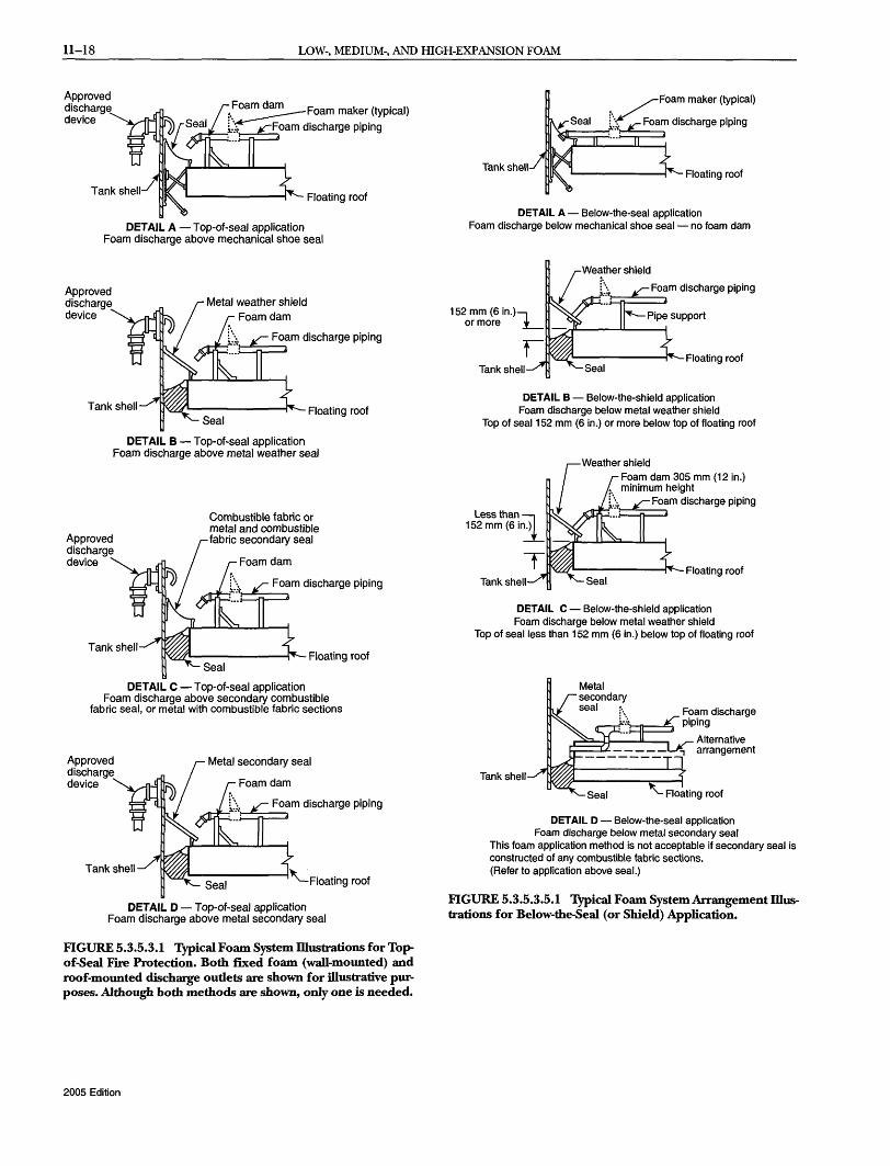
11-18 LOW-, MEDIUM-, AND HIGH-EXPANSION FOAM
Approved discharge device
Floating roof
DETAIL A - Top-of-seal application Foam discharge above mechanical shoe seal
Approved discharge device
Foam discharge piping rt::;_··!=:;::;:=:::::l
Floating roof
DETAIL B - Top-of-seal application Foam discharge above metal weather seal
Approved discharge device
Combustible fabric or metal and combustible fabric secondary seal
Foam discharge piping ~t:f·''t:~;::;:::::l
mlL.--_____ ~- Floating roof
DETAIL C - Top-of-seal application Foam discharge above secondary combustible
fabric seal, or metal with combustible fabric sections
Approved discharge device Foam dam
Foam discharge piping Jdtit=t·_·t==n:~
DETAIL D - Top-ot-seal application Foam discharge above metal secondary seal
FIGURE 5.3.5.3.1 Typical Foam System Dlustrations for Topof -Seal Fire Protection. Both fixed foam (wall-mounted) and roof-mounted discharge outlets are shown for illustrative purposes. Although both methods are shown, only one is needed.
2005 Edition
Tank shell
./Foam maker (typical)
tf" Foam discharge piping ~=;:;:::j
L..-_____ --1"'- Floating roof
DETAIL A - Below-the-seal application Foam discharge below mechanical shoe seal - no foam dam
Foam discharge piping ~:~"J:::n:==:::l
1T'((;(UIL.--------i'~Floating roof TanksheU
DETAIL B - Below-the-shield application Foam discharge below metal weather shield
Top of seal 152 mm (6 in.) or more below top of floating roof
TanksheU
Weather shield Foam dam 305 mm (12 in.) minimum height
Foam discharge piping ~:[::C:=n=~
q ... ------~- Floating roof
DETAIL C - Below-the-shield application Foam discharge below metal weather shield
Top of seal less than 152 mm (6 in.) below top of floating roof
TanksheU
Alternative arrangement
DETAIL D - Below-the-seal application Foam discharge below metal secondary seal
This foam application method is not acceptable if secondary seal is constructed of any combustible fabric sections. (Refer to application above seal.)
FIGURE 5.3.5.3.5.1 Typical Foam System Arrangement Dlustrations for Below-the-Seal (or Shield) Application.

LOW-EXPANSION SYSTEM DESIGN 11-19
Table 5.3.5.3.6.1 Below-thNeal Fixed Foam Discharge Protection for Open-Top Floating Roof Tanks
Minimum Applicable Application Rate IDustration
Seal Type Detail L/min.m2 gpm/ft2
Mechanical shoe A 20.4 0.5 seal
Tube seal with B 20.4 0.5 more than 152 mm (6 in.) between top of tube and top of pontoon
Tube seal with less C 20.4 0.5 than 152 mm (6 in.) between top of tube and top of pontoon
Tube seal with D 20.4 0.5 foam discharge below metal secondary seal*
*A metal secondary seal is equivalent to a foam dam.
5.3.5.4.3.3 Dam height shall be at least 51 mm (2 in.) higher than any burnout panels in metal secondary seals.
5.3.5.4.4 The foam dam shall be at least 0.3 m (1 ft), but not more than 0.6 m (2 ft), from the tank shell.
5.3.5.4.5 To allow drainage of rainwater, the foam dam bottom shall be slotted on the basis of278 mm2 of slot area per m2
of dammed area (0.04 in.2 of slot area per ft2 of dammed area), restricting drain slots to a maximum 9.5 mm (% in.) in height as shown in Figure 5.3.5.4.5.
5.3.5.4.6 Excessive dam openings for drainage shall be avoided to prevent loss offoam through the drainage slots.
5.3.6* Foam Handline Design Criteria for Seal Area Protection.
5.3.6.1 Foam handlines shall be permitted to be used from the windgirder for extinguishment of seal fires in open-top floating roof tanks.
5.3.6.2 Listed or approved equipment shall be used.
5.3.7 Foam Monitor Design Criteria for Seal Area Protection. Monitors shall not be used as the primary means of floating roof seal fire extinguishment because of the difficulty of directing foam into the annular space and the possibility of sinking the roof.
5.4* Outdoor Covered (Internal) Floating Roof Tanks. See Figure 5.4.
5.4.1 Requirements for tanks equipped with the following floating roof types shall not be covered in Section 5.4:
(1) Roofs made from floating diaphragms (2) Roofs made from plastic blankets
Maximum Minimum Spacing Between Discharge Discharge
Time (min) (Outlets)
10 39 m (130 ft) -Foam dam not required
10 18 m (60 ft)-Foam dam not required
10 18 m (60 ft)-Foam dam required
10 18m (60ft)-Foam dam not required
(3) Roofs made with plastic or other flotation material, even if encapsulated in metal or fiberglass
(4) Roofs that rely on flotation device closures that can be easily submerged if damaged
(5) Pan roofs
Note: Dam height to be at least 50.8 mm (2 in.) above top of seal
FIGURE 5.3.5.4.5 Typical Foam Dam for Floating Roof Tank Protection.
2005 Edition

11-20 LOW-, MEDIUM-, AND HIGH-EXPANSION FOAM
Automatic tank gauge piping
Step-on thief hatch located over sample well -+~t--''''
Optional overflow vent'
4.06 mm (Va in.) S. S. ground cables
Automatic gauge float
Sample well
Shell manway
Floating roof seal
FlGURE 5.4 Typical Covered Floating Roof Tank.
5.4.2 The following types of roof construction shall be considered suitable for seal area protection systems:
(1) Steel double deck (2) Steel pontoon (3) Full liquid surface contact, metallic sandwich panel, con
forming to Appendix H, "Internal Floating Roofs" requirements of API 650
5.4.2.1 All other types of roof construction shall require full surface protection.
5.4.2.2 Design for Full Surface Fire.
5.4.2.2.1 Where the basis for design is a full surface fire, the covered (internal) floating roof tank shall be considered as equivalent to a fixed-roof (cone) tank of the same diameter for the purpose of foam system design.
5.4.2.2.2 For a full surface fire, the foam facilities shall be designed in accordance with 5.2.3 and Section 5.9, except that separately valved laterals for each foam discharge shall not be required.
5.4.2.2.3 For this application, fixed foam discharge outlets shall not be fitted with a frangible vapor seal device.
5.4.2.2.4 Subsurface and semisubsurface injection shall not be used because of the possibility of improper distribution of foam.
2005 Edition
0~~~IiI""liIIItii~".~~A~ntirotation roof fitting Peripheral roof venti inspection hatch
Antirotation cable passes through fitting bolted to rim plate
Antirotation lug welded to floor
Tank support column with column well
Cover access hatch
Vacuum breaker and actuator leg
5.4.2.3 Design for Seal Area Fire.
5.4.2.3.1 Where the basis for design is a seal fire, the covered (internal) floating roof tank shall be considered as equivalent to an open-top floating roof tank of the same diameter for the purpose of foam system design.
5.4.2.3.2 For a seal fire, the foam discharge system shall be designed in accordance with the requirements specified in Table 5.3.5.3.1 utilizing fixed foam discharge outlets.
5.4.2.3.3 Supplementary Protection. In addition to the primary means of protection, there shall be provisions for supplementary protection in accordance with the requirements of Section 5.9.
5.4.2.3.4* Basis of Design.
5.4.2.3.4.1 System design shall be based on protecting the tank requiring the largest solution flow, including supplementary hose streams.
5.4.2.3.4.2 If the application rate is higher than the minimum rate specified in Table 5.2.6.5.1, the discharge time shall be permitted to be reduced proportionately, but shall not be less than 70 percent of the minimum discharge times specified.
5.5 Indoor Hazards.
5.5.1 * This section shall address foam fire-extinguishing systems, which are intended to protect indoor storage tanks that have liquid surface areas of 37.2 m2 (400 ft2
) or greater.

LOW-EXPANSION SYSTEM DESIGN 11-21
5.5.2 Discharge Outlets. Tanks for storing liquid hydrocarbons shall be fitted with Type II, tank-mounted fixed foam discharge outlets as specified in Table 5.2.6.2.8.
5.5.3 Minimum Discharge TlDle and Application Rate.
5.5.3.1 The minimum application rate for indoor hydrocarbon storage tanks shall be 6.5 L/min.m2 (0.16 gpm/ft2) of liquid surface area.
5.5.3.2 Minimum discharge time shall be as specified in Table 5.2.5.2.2 for Type II fixed foam discharge outlets.
5.5.3.3 If the application rate is higher than the minimum rate specified in 5.5.2, the discharge time shall be permitted to be reduced proportionately, but not to less than 70 percent of the minimum discharge times indicated.
5.5.4 Design Criteria for Indoor Storage Tanks Containing Flammable or Combustible Liquids Requiring AlcoholResistant Foams.
5.5.4.1 * Water-soluble and certain flammable and combustible liquids and polar solvents that are destructive to nonalcohol-resistant foams shall require the use of alcoholresistant foams.
5.5.4.2 In all cases, the manufacturers of the foam concentrate and the foam-making equipment shall be consulted as to limitations and for recommendations based on listings or specific fire tests.
5.6* Loading Racks.
5.6.1 Within the scope of this standard, loading racks shall be defined as being either truck or rail car types for the purpose of loading or unloading product.
5.6.2 Total rack size, flammable or combustible products involved, proximity of other hazards and exposures, drainage facilities, wind conditions, ambient temperatures, and available staff all shall be considered in the design of a loading rack foam system.
5.6.3 Methods of Protection. The following shall be permitted to be two acceptable methods of protecting loading racks:
(1) Foam-water sprinkler application utilizing air-aspirating foam-water sprinklers or nozzles or non-air-aspirating standard sprinklers
(2) Foam monitors
5.6.4 Design Criteria for Foam-Water Sprinkler Systems. The design criteria for sprinkler systems shall be in accordance with NFPA 16.
5.6.5 Design Criteria for Foam Monitor Protection Systems.
5.6.5.1 * Areas to Be Protected by Monitor Nozzles. Monitor nozzle system design shall be based on the total ground area.
5.6.5.2* The intent of the design shall be to protect the canopy, pumps, meters, vehicles, and miscellaneous equipment associated with the loading and unloading operation in the event of a spill fire.
5.6.5.3 Minimum Application Rates and Discharge TlDles.
5.6.5.3.1 Minimum foam application rates and discharge times for loading racks protected by monitor nozzles shall be as specified in Table 5.6.5.3.1.
5.6.5.3.2 If a fuel depth of more than 25.4 mm (1 in.) can accumulate within the protected area, the application rate shall be increased to 6.5 L/min.m2 (0.16 gpm/ft2).
5.7* Diked Areas - Outdoor.
5.7.1 For the purpose of this standard, diked areas shall be areas bounded by contours of land or physical barriers that retain a fuel to a depth greater than 25.4 mm (1 in.).
5.7.2 Protection of these areas shall be achieved by either fixed discharge outlets, fixed or portable monitors, or foam hoselines.
5.7.3 Methods of Application. Where foam protection is used for a diked area, it shall be permitted to be accomplished by any of the following methods:
(1) Low-level foam discharge outlets (2) Foam monitors or foam hoselines (3) Foam-water sprinklers or nozzles
5.7.3.1 This list of methods shall not be considered as being in the order of preference.
5.7.3.2 Minimum Application Rates and Discharge TlDles for Fixed Discharge Outlets on Diked Areas Involving Liquid Hydrocarbons. The minimum application rates and discharge times for fixed foam application on diked areas shall be as specified in Table 5.7.3.2.
5.7.3.3* Fixed Foam Discharge Outlets.
5.7.3.3.1 Fixed foam discharge outlets shall be sized and located to apply foam uniformly over the dike area at the application rate specified in Table 5.7.3.2.
5.7.3.3.2 Large dike areas shall be permitted to be subdivided to keep the total design solution within practical limits.
5.7.3.4 Fixed Foam-Water Sprinklers or Nozzles.
5.7.3.4.1 Where fixed foam-water sprinklers or nozzles are used, the system design shall be in accordance with NFPA 16.
5.7.3.4.2* Where foam-water sprinklers or nozzles are used as the primary protection, consideration shall be given to the possibility that some of the foam discharge can be carried by the wind beyond the area of the fuel spill.
5.7.3.5 Fixed Low-Level Foam Discharge Outlets.
5.7.3.5.1 Fixed low-level foam discharge outlets shall be permitted to be open pipe fittings or directional flow nozzles designed to discharge a compact, low-velocity foam stream onto the inner wall of the dike or - where necessary - directly onto the dike floor.
5.7.3.5.2 Fixed low-level foam discharge outlets shall be located around the dike wall, and - where necessary - inside the dike area, to apply foam uniformly over the dike area.
5.7.3.5.3* Limitations.
5.7.3.5.3.1 Where fixed discharge outlets installed at a low level are used as the primary protection, they shall be located so that no point in the dike area is more than 9 m (30 ft) from a discharge outlet where the discharge per outlet is 225 L/ min (60 gpm) or less.
5.7.3.5.3.2 For outlets having discharge rates higher than 225 L/min (60 gpm), the maximum distance between discharge outlets shall be 18 m (60 ft).
2005 Edition

11-22 LOW-, MEDIUM-, AND HIGH-EXPANSION FOAM
Table 5.6.5.3.1 Minimum Application Rates and Discharge Tunes for Loading Racks Protected by Foam Monitor Nozzle Systems
Minimum Application Rate Minimum
L/min ·m2 gpm/fr Discharge Product Being
Foam Type Time (min) Loaded
Protein and fluoroprotein AFFF,FFFP,and
alcohol-resistant AFFF orFFFP
Alcohol-resistant foams
6.5 0.16 4.1 0.10
Consult manufacturer for listings on specific
products
15 15
15
Hydrocarbons Hydrocarbons
Flammable and combustible liquids requiring alco hol-resistan t foam
Table 5.7.3.2 Minimum Application Rates and Discharge Tunes for Fixed Foam Application on Diked Areas Involving Hydrocarbon Liquids
Minimum Application Rate
Type of Foam Discharge Outlets L/min. m 2 gpm/ft2
Low-level foam 4.1 0.10 discharge oudets
Foam monitors 6.5 0.16
5.7.3.5.4 Foam Monitors. Where monitors are used to discharge foam onto the dike area, they shall be located outside the dike area.
5.7.3.5.4.1 Where foam monitors are used as the primary protection, consideration shall be given to the possibility that some of the foam discharge can be carried by the wind beyond the area of the fuel spill.
5.7.3.5.4.2 Where the monitor discharge is in the form of a compact, high-velocity foam stream, it shall be directed against the dike walls, tank surfaces, or other structures to prevent its plunging direcdy into the burning liquid surface.
5.7.4 Diked Areas Involving Flammable or Combustible Liquids Requiring Alcohol-Resistant Foams.
5.7.4.1 Water-soluble and certain flammable and combustible liquids and polar solvents that are destructive to nonalcohol-resistant foams shall require the use of alcoholresistant foams.
5.7.4.2 Systems using these foams shall require special engineering consideration.
5.7.4.3 The design criteria for diked areas involving flammable or combustible liquids requiring alcohol-resistant foams shall be as stated in 5.7.4.3.1 through 5.7.4.3.3.
5.7.4.3.1 Methods of fixed protection shall be the same as those described in 5.7.3.3 for hydrocarbon hazards.
5.7.4.3.2 Application rates shall be in accordance with manufacturer recommendations based on listings or approvals for specific products and corresponding foam-making devices.
2005 Edition
Minimum Discharge Time (min)
Class I Class II Hydrocarbon Hydrocarbon
30 20
30 20
5.7.4.3.3 The minimum discharge time shall be 30 minutes.
5.8* Nondiked Spill Areas.
5.8.1 Description of Areas. For the purpose of this standard, non diked spill areas shall be areas where a flammable or combustible liquid spill might occur, uncontained by curbing, dike walls, or walls of a room or building.
5.8.2 Design Criteria for Protection of Spill Fires Involving Hydrocarbons or Flammable and Combustible Liquids Requiring Alcohol-Resistant Foams.
5.8.2.1 To determine protection for spill fires, the potential spill area shall be estimated.
5.8.2.2 Once this area has been determined, Table 5.8.2.2 shall be used to calculate requirements to be used as design criteria for portable nozzles or monitors.
5.9* Supplementary Protection.
5.9.1 Additional Protection. In addition to the primary means of protection, some types of hazards shall require provisions for supplemental means of protection.
5.9.2 Supplemental Foam Hose Stream Requirements.
5.9.2.1 Approved foam hose stream equipment shall be provided in addition to tank foam installations as supplementary protection for small spill fires.
5.9.2.2 The minimum number of fixed or portable hose streams required shall be as specified in Table 5.9.2.2 and shall be available to provide protection of the area.

MEDIUM- AND HIGH-EXPANSION SYSTEMS 11-23
Table 5.8.2.2 Minimum Application Rate and Discharge Tunes for N ondiked Spill Fire Protection Using Portable Foam Nozzles or Monitors
Minimum Application Rate Minimum -------------- Discharge Time Anticipated
Product Spill Foam Type gpm/fr
6.5 0.16
4.1 0.10
Protein and fluoroprotein
AFFF,FFFP,and alcohol-resistan t AFFForFFFP
Alcohol-resistan t foams
Consult manufacturer for listings on specific products
Table 5.9.2.2 Supplemental Foam Hose Stream Requirements Diameter of Largest Tank
Diameter of Largest Tank
Up to 19.5 m (65 ft) 19.5 to 36 m (65 to 120 ft) Over 36 m (120 ft)
Minimum Number of Hose Streams
Required
1 2 3
Table 5.9.2.4 Hose Stream Operating Tunes, Supplementing Tank Foam Installations
Diameter of Largest Tank
Up to 10.5 m (35 ft) 10.5 to 28.5 m (35 to 95 ft) Over 28.5 m (95 ft)
Minimum Operating Time*
10 min 20 min 30 min
*Based on simultaneous operation of the required minimum number of hose streams discharging at a rate of 189 L/min (50 gpm).
5.9.2.3 The equipment for producing each foam stream shall have a solution application rate of at least 189 L/min (50 gpm) , with the minimum number of hose streams shown in Table 5.9.2.2.
5.9.2.4 Additional foam-producing materials shall be provided to allow operation of the hose stream equipment simultaneously with tank foam installations as specified in Table 5.9.2.4.
Chapter 6 Mediurn- and High-Expansion Systems
6.1 * General Information and Requirements. This chapter shall apply to requirements for a design of medium- and high-expansion foam systems.
(min)
15
15
15
Hydrocarbon
Hydrocarbon
Flammable and combustible liquids requiring alcohol-resistant foam
6.2 Use and Limitations.
6.2.1 Medium- and high-expansion foams shall be specifically evaluated to verify the applicability of medium- or high-expansion foam as a fire control agent for the type of hazard being considered for application of foam.
6.3* Hazards Protected. Hazards that medium- and highexpansion foam systems shall be permitted to protect include the following:
(1) Ordinary combustibles (2) Flammable and combustible liquids (3) Combinations of (1) and (2) (4) Liquefied natural gas (high-expansion foam only)
6.3.1 Susceptibility of the protected hazard to water damage shall be evaluated.
6.3.2* Medium- and high-expansion foam systems shall not be used on fires in the following hazards:
(1) Chemicals, such as cellulose nitrate, that release sufficient oxygen or other oxidizing agents to sustain combustion
(2) Energized unenclosed electrical equipment (3) Water-reactive metals such as sodium, potassium, and NaK
(sodium-potassium alloys) (4) Hazardous water-reactive materials, such as triethyl
aluminum and phosphorus pentoxide (5) Liquefied flammable gas (6) Hazards listed in (1)-(5) where competent evaluation, in-
cluding tests, indicates acceptability
6.4 Types of Systems. The types of systems within the scope of this standard shall be provided as follows:
(1) Total flooding systems (2) Local application systems (3) Portable foam-generating devices
6.5 Systems Protecting One or More Hazards.
6.5.1 Systems shall be permitted to be used to protect one or more hazards or groups of hazards by means of the same supply of foam concentrate and water.
6.5.2 Where, in the opinion of the AHj, two or more hazards can be simultaneously involved in fire by reason of their proximity, each hazard shall be protected with an individual system, or the system shall be arranged to discharge on all potentially involved hazards simultaneously.
2005 Edition

11-24 LOW-, MEDIUM-, AND HIGH-EXPANSION FOAM
6.6* Personnel Safety.
6.6.1 * Where possible, the location of foam discharge points relative to building exits shall be arranged to facilitate evacuation of personnel.
6.6.1.1 * To re-enter a foam-filled building, a coarse water spray shall be permitted to be used to cut a path in the foam. Personnel shall not enter the foam.
6.6.1.2* A canister-type gas mask shall not be worn in the foam.
6.6.1.2.1 If emergency reentry is essential, self-contained breathing apparatus shall be used in conjunction with a lifeline.
6.6.1.3 Unenclosed electrical apparatus shall be de-energized upon system actuation unless it has been deemed unnecessary by competent evaluation.
6.6.2* Electrical Clearances.
6.6.2.1 All system components shall be located to maintain minimum clearances from live parts as shown in Table 6.6.2.1.
Table 6.6.2.1 Oearance from Medium- and High-Expansion Foam Equipment to Live Uninsulated Electrical Components
Nominal Nominal Minimum Line Voltage to
Voltage Ground Desi~ Clearance2
BIL (kV) (kV) (kV) mm in.
To 15 T09 110 178 7 23 13 150 254 10
34.5 20 200 330 13 46 27 250 432 17 69 40 350 635 25 115 66 550 940 37 138 80 650 1118 44 161 93 750 1321 52
196-230 114-132 900 1600 63 1050 1930 76 1175 2210 87 1300 2489 98
287-380 166-220 1425 2769 109 1550 3048 120
500 290 1675 3327 131 1800 3607 142 1925 3886 153
500-700 290-400 2100 4267 168 2300 4674 184
IBasic insulation level (BIL) values are expressed as kilovolts (kV), the number being the crest value of the full wave impulse test that the electrical equipment is designed to withstand. 2Forvoltages up to 69 kYo the clearances are taken from NFPA 70.
6.6.2.2 The clearances given are for altitudes of 1000 m (3300 ft) or less.
6.6.2.2.1 * At altitudes in excess of 1000 m (3300 ft), the clearance shall be increased at the rate of 1 percent for each 100 m (330 ft) increase in altitude above 1000 m (3300 ft).
6.6.2.2.2 To coordinate the required clearance with the electrical design, the design BIL of the equipment being protected shall be used as a basis, although this is not material at nominal line voltages of 161 kV or less.
2005 Edition
6.6.2.2.3 At voltages higher than 161 kV, uniformity in the relationship between design BIL kVand the various electrical system voltages has not been established in practice and is dependent on several variables so that the required clearances to ground shall be based on the design BIL used rather than on the nominal line or ground voltage.
6.6.2.2.4 The clearance between uninsulated energized parts of the electrical system equipment and any portion of the medium- or high-expansion foam system shall not be less than the minimum clearance provided elsewhere for electrical system insulations on any individual component.
6.7 Operation and Control of Systems.
6.7.1 * Detection of FIreS.
6.7.1.1 Automatic detection shall be used for fixed systems.
6.7.1.1.1 * Removal of automatic detection shall be permitted when approved by the AHJ.
6.7.1.2* Automatic detection shall be by listed or approved methods or devices capable of detection and indicating heat, smoke, or flame. Automatic detection devices shall be installed in accordance with NFPA 72.
6.7.1.3 Detection by the use of combustible vapor detectors or an abnormal condition in the hazard such as process trouble, likely to produce fire, shall be arranged using acceptable industrial practices as specified by an engineering study.
6.7.1.4* A reliable source of energy shall be used in detection systems.
6.7.1.4.1 The power supply for electrical detection systems shall be independent of the supply for the protected area.
6.7.1.4.2 Arrangement of the power supply shall be in accordance with requirements of NFPA 72 for continuity of power supplies.
6.7.2 Supervision. Supervision of automatic detection and actuation equipment shall be provided and arranged so that there will be an immediate indication of failure, preferably at a constantly attended location.
6.7.3 Alarms.
6.7.3.1 Audible alarms shall be installed to indicate the operation of the system, to alert personnel, and to indicate failure of any supervised device or equipment.
6.7.3.2 Such devices shall be of such a type and shall be provided in such numbers and at such locations as are necessary to accomplish their purpose satisfactorily.
6.7.3.3 An alarm shall be provided to show that the system has operated.
6.7.3.4 Alarms shall be provided to give ample warning of discharge where hazards(s) to personnel might exist.
6.7.3.5 Alarms indicating failure of supervised devices or equipment shall give prompt and positive indication of any failure and shall be distinctive from alarms indicating operation or hazardous conditions.
6.7.4* Operating Devices.
6.7.4.1 Operating devices shall include foam generators, valves, proportioners, eductors, discharge controls, and shutdown equipment.

MEDIUM- AND HIGH-EXPANSION SYSTEMS 11-25
6.7.4.1.1 Operation shall be controlled by listed or approved mechanical, electrical, hydraulic, or pneumatic means.
6.7.4.1.2 A reliable source of energy shall be used.
6.7.4.1.3 The electrical power supply for an electrically operated medium- or high-expansion foam system shall be as reliable as a fire pump circuit in accordance with NFPA 20.
6.7.4.2 All operating devices shall be suitable for the service they will encounter and shall not be readily rendered inoperative or susceptible to accidental operation.
6.7.4.2.1 Provision shall be made to protect piping that is normally filled with liquid from freezing.
6.7.4.3 All devices shall be located, installed, or suitably protected so that they are not subject to mechanical, chemical, climatic, or other conditions that will render them inoperative.
6.7.4.4 Manual controls for actuation and shutdown shall be conveniendy located and easily accessible at all times, including the time of fire and system operation.
6.7.4.4.1 Remote control stations for manual actuation should be considered where the area is large, egress difficult, or where required by the AHJ.
6.7.4.4.2 Manual controls for actuation shall operate the system to the same extent as the automatic control.
6.7.4.5 All automatically operated equipment controlling the generation and distribution of foam shall be provided with approved independent means for emergency manual operation.
6.7.4.5.1 If the means for manual actuation of the system required in 6.7.1 provide approved positive operation independent of the automatic actuation, it shall be permitted to be used as the emergency means.
6.7.4.5.2 The emergency means, preferably mechanical, shall be easily accessible and located close to the equipment controlled.
6.7.4.5.3 If possible, the system shall be designed so that complete emergency actuation can be accomplished from one location.
6.7.4.6 All required door and window closers, vent openers, and electrical equipment shutdown devices shall be considered integral parts of the system and shall function simultaneously with the system operation.
6.7.4.7 All manual operating devices shall be identified with signs as to the hazards they protect.
6.S Foam Concentrate.
6.S.1 Quality. (See Annex H.)
6.S.1.1 The foam concentrate used in the system shall be listed for use with the equipment.
6.S.1.2 The quality of the concentrate for proper performance under the installation requirements of this standard shall be determined by suitable tests.
6.9 Air Supply.
6.9.1 Air from outside the hazard area shall be used for foam generation unless data is provided to show that air from inside the hazard can be successfully employed.
6.9.2 The data shall be specific for the products of combustion to be encountered and shall provide factors for increasing foam discharge rates over those given in 6.12.8 if fire tests indicate that need.
6.9.3 Vents from the fire area shall be located to avoid recirculation of combustion products or other materials deleterious to the formation of foam into foam generator air inlets.
6.10 Foam-Generating Apparatus Location.
6.10.1 Accessibility for Inspection and Maintenance. Foamgenerating apparatus shall be located and arranged so that inspection, testing, recharging, and other maintenance is facilitated and interruption of protection is held to a minimum.
6.10.2* Protection Against Exposure.
6.10.2.1 Foam-generating equipment shall be located as close as possible to the hazard(s) it protects, but not where it will be unduly exposed to a fire or explosion.
6.10.2.2 Foam generators installed inside the hazard area shall be listed to resist or be protected against fire exposure for the duration of the fire.
6.10.2.3 Such protection shall be permitted to be in the form of insulation, water spray or sprinklers, or other method as determined by an engineering study. In certain applications, additional generators shall be permitted to be substituted for fire exposure protection based on results of fire tests.
6.11 Distribution Systems.
6.11.1 Piping and Fittings. Piping and fittings shall conform to the requirements of Chapter 4.
6.11.2 Arrangement and Installation of Piping and Fittings.
6.11.2.1 A listed strainer suitable for use with the proportioner and foam generator shall be provided in the water line upstream of the water valve.
6.11.2.2 Supplemental strainers shall be permitted to be used as recommended by the foam equipment manufacturer.
6.11.3 Ducts.
6.11.3.1 Foam distribution and air inlet ducts shall be designed, located, installed, and suitably protected so that they are not subject to undue mechanical, chemical, or other damage.
6.11.3.2 Duct closures such as selector valves, gates, or doors shall be of the quick-opening type, so as to allow free passage of the foam.
6.11.3.2.1 When duct closures are located where they might be subjected to fire or heat exposure, either inside or outside the area to be protected, special care shall be taken to ensure positive operation.
6.11.3.3 Ducts shall be designed and installed so that undue turbulence is avoided, and the actual foam discharge rate shall be determined by test or other method acceptable to theAHJ.
6.12 Total Flooding Systems General Information.
6.12.1 Description. A total flooding system shall consist of fixed foam-generating apparatus complete with a piped supply of foam concentrate and water, arranged to discharge into an enclosed space or enclosure around the hazard.
2005 Edition

11-26 LOW-, MEDIUM-, AND HIGH-EXPANSION FOAM
6.12.2* Applications. Total flooding systems are permitted to be used where an adequate permanent enclosure is provided around the hazard to enable the required amount of fireextinguishing medium to accumulate at the proper depth and to be maintained for a period of time required to ensure fire control or extinguishment in a specific combustible material.
6.12.3 General Requirements.
6.12.3.1 Total flooding systems shall be designed, installed, tested, and maintained in accordance with the applicable requirements of this standard.
6.12.3.2 Only listed or approved equipment and devices shall be used in these systems.
6.12.4 Total Flooding Enclosure Specifications.
6.12.4.1 * Leakage.
6.12.4.1.1 Openings. Openings below design filling depth, such as doorways and windows, shall be arranged to close automatically before, or simultaneously with, the start of the foam discharge, with due consideration for evacuation of personnel.
6.12.4.1.1.1 Openings shall be designed to maintain closure during a fire and shall be capable of withstanding pressures of foam and sprinkler water discharge.
6.12.4.1.1.2 Where openings cannot be protected by automatic closing devices, the total flooding system shall be designed to compensate for the probable loss of foam.
(A) The suitability of the system design shall be tested to ensure proper performance.
(B) If the foam system can be started prior to complete closure of the space to be filled, additional foam output shall be allowed to compensate for the losses.
(C) This shall be verified by test based on the individual site conditions.
6.12.4.1.2 Ventilation.
6.12.4.1.2.1 Where outside air is used for foam generation, high-level venting shall be provided for air that is displaced by the foam.
6.12.4.1.2.2 Venting velocity shall not exceed 305 m/min (1000 ft/min) in free air.
6.12.4.1.2.3 The required venting shall consist of suitable openings, either normally open or normally closed and arranged to open automatically when the system operates.
6.12.4.1.2.4 Where design criteria demand exhaust fans, they shall be approved for high-temperature operation and installed with consideration for protection of switches, wiring, and other electrical devices to ensure equal reliability of exhaust fan performance. Operation of the fans shall not compromise foam generator operations.
6.12.4.1.2.5 Where forced-air ventilating systems interfere with the proper buildup of foam, they shall be automatically shut down or closed.
6.12.5 Foam Requirements.
6.12.5.1 General. For adequate protection, total flooding medium- or high-expansion foam shall be discharged at a rate sufficient to fill the enclosure to an effective depth above the hazard before an unacceptable degree of damage occurs.
2005 Edition
6.12.5.2 Foam Depth.
6.12.5.2.1 High-Expansion Foam.
6.12.5.2.1.1 The minimum total depth of foam shall be not less than 1.1 times the height of the highest hazard but in no case less than 0.6 m (2 ft) over this hazard.
6.12.5.2.1.2 For flammable or combustible liquids, the required depth over the hazard shall be permitted to be considerably greater than the requirement of 6.12.5.2.1.1 and shall be no less that than the depth determined by tests. Tests shall duplicate the anticipated fire event in the protected area.
6.12.5.2.2 Medium-Expansion Foam.
6.12.5.2.2.1 Required depth over the hazard shall vary with expansion.
6.12.5.2.2.2 Depth shall be determined by tests. (See 6.12.6.2. SeeAnnex H.)
6.12.6 Submergence Volume for High-Expansion Foams.
6.12.6.1 Submergence volume for sprinkler protected areas shall be defined as the depth as specified in 6.12.5.2.2.2 multiplied by the floor area of the space to be protected, 6.12.3. Submergence volume for unsprinklered rooms of combustible construction or finish shall be based on the entire volume, including concealed spaces.
6.12.6.2 The volume occupied by vessels, machinery, or other permanently located equipment shall be permitted to be deducted when determining the submergence volume.
6.12.6.3 The volume occupied by stored material shall not be deducted when determining the submergence volume.
6.12.7* Submergence TIme for High-Expansion Foams.
6.12.7.1 Recommended times to achieve submergence volume for various types of hazards and building construction shall be as shown in Table 6.12.7.1.
6.12.7.2 Shorter submergence times shall be permitted to be required depending on the factors included in 6.12.8.
6.12.7.3 The submergence time shall be based on a maximum of 30 seconds delay between fire detection and start of foam discharge. Any delays in excess of 30 seconds shall be deducted from the submergence times in Table 6.12.7.1.
6.12.7.4 Where use of high -expansion foam on polar solvents is contemplated, the foam equipment supplier shall substantiate suitability for the intended use.
6.12.8* Rate of Discharge.
6.12.8.1 Medium-Expansion Foam. The rate of discharge for medium-expansion foam shall be determined by tests.
6.12.8.2 High-Expansion Foam.
6.12.8.2.1 * The rate of foam discharge necessary for extinguishment or sufficient control to permit overhaul shall be dependent on the strength of sprinkler protection, the nature and configuration of the hazard, the vulnerability of the structure and contents to fire, and the loss potential to life, property, and production.
6.12.8.2.2 The foam discharge rate shall be sufficient to satisfy the foam depth requirements and submergence times of Table 6.12.7.1, with compensation for normal foam shrinkage, foam leakage, and breakdown effects of sprinkler discharge.
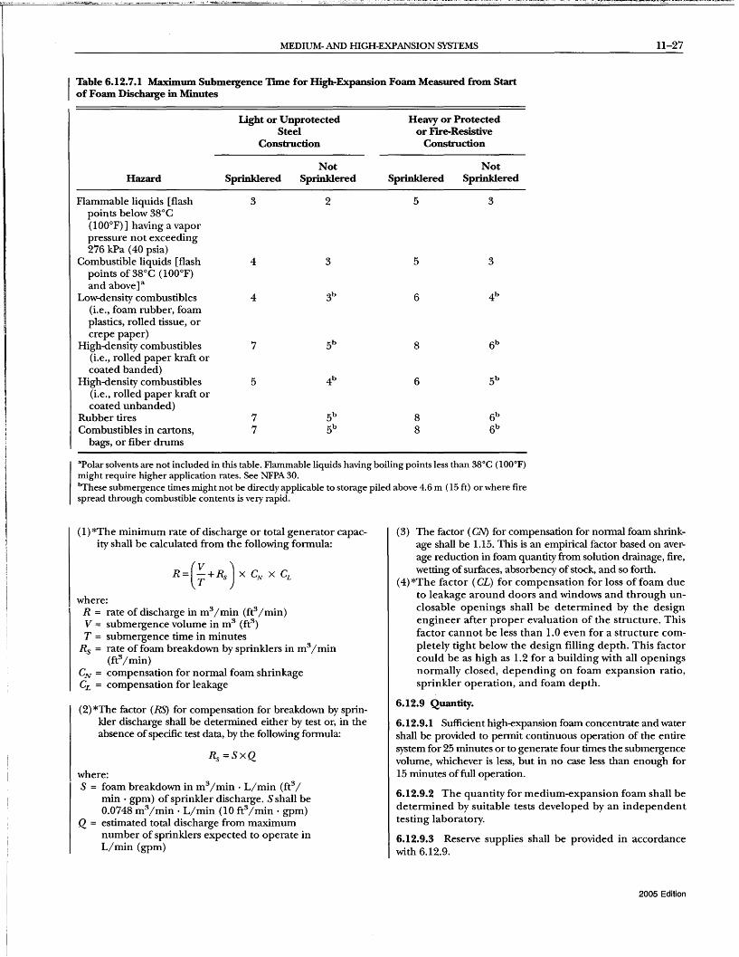
MEDIUM- AND HIGH-EXPANSION SYSTEMS 11-27
Table 6.12.7.1 Maximum Submergence Tune for High-Expansion Foam Measured from Start of Foam Discharge in Minutes
Light or Unprotected Steel
Construction
Hazard Sprinldered
Flammable liquids [flash 3 points below 38°C (1 OO°F)] having a vapor pressure not exceeding 276 kPa (40 psia)
Combustible liquids [flash 4 points of 38°C (100°F) and above]a
Low-density combustibles 4 (i.e., foam rubber, foam plastics, rolled tissue, or crepe paper)
High-density combustibles 7 (i.e., rolled paper kraft or coated banded)
High-density combustibles 5 (i.e., rolled paper kraft or coated unbanded)
Rubber tires 7 Combustibles in cartons, 7
bags, or fiber drums
Not Sprinldered
2
3
Heavy or Protected or FIre-Resistive
Construction
Sprinldered
5
5
6
8
6
8 8
Not Sprinldered
3
3
apolar solvents are not included in this table. Flammable liquids having boiling points less than 38°C (lOO°F) might require higher application rates. See NFPA 30. ~hese submergence times might not be directly applicable to storage piled above 4.6 m (15 ft) or where fire spread through combustible contents is very rapid.
(1) *The minimum rate of discharge or total generator capacity shall be calculated from the following formula:
where: R = rate of discharge in m3/min (ft3/min) V = submergence volume in m3 (fe) T = submergence time in minutes
Rs = rate of foam breakdown by sprinklers in m3/ min (ft3/min)
CN = compensation for normal foam shrinkage CL = compensation for leakage
(2)*The factor (RS) for compensation for breakdown by sprinkler discharge shall be determined either by test or, in the absence of specific test data, by the following formula:
where: S = foam breakdown in m3/min . L/min (ft3/
min· gpm) of sprinkler discharge. S shall be 0.0748 m3/min . L/min (10 ft3/ min . gpm)
Q = estimated total discharge from maximum number of sprinklers expected to operate in L/min (gpm)
(3) The factor (eN) for compensation for normal foam shrinkage shall be 1.15. This is an empirical factor based on average reduction in foam quantity from solution drainage, fire, wetting of surfaces, absorbency of stock, and so forth.
(4) *The factor (CL) for compensation for loss of foam due to leakage around doors and windows and through unclosable openings shall be determined by the design engineer after proper evaluation of the structure. This factor cannot be less than 1.0 even for a structure completely tight below the design filling depth. This factor could be as high as 1.2 for a building with all openings normally closed, depending on foam expansion ratio, sprinkler operation, and foam depth.
6.12.9 Quantity.
6.12.9.1 Sufficient high-expansion foam concentrate and water shall be provided to permit continuous operation of the entire system for 25 minutes or to generate four times the submergence volume, whichever is less, but in no case less than enough for 15 minutes of full operation.
6.12.9.2 The quantity for medium-expansion foam shall be determined by suitable tests developed by an independent testing laboratory.
6.12.9.3 Reserve supplies shall be provided in accordance with 6.12.9.
2005 Edition
11-28 LOW-, MEDIUM-, AND HIGH-EXPANSION FOAM
6.12.10* Maintenance of Submergence Volume for HighExpansion Foam.
6.12.10.1 To ensure adequate control or extinguishment, the submergence volume shall be maintained for at least 60 minutes for unsprinklered locations and 30 minutes for sprinklered locations.
6.12.10.2 Where the hazard consists of flammable or combustible liquids in noncombustible containers, the time in 6.12.10.1 shall be permitted to be reduced.
6.12.10.3 Method.
6.12.10.3.1 The submergence volume shall be permitted to be maintained by continuous or intermittent operation of any or all of the generators provided.
6.12.10.3.2 Arrangements and procedures shall be provided to maintain the submergence volume without waste of foam concentrate that might be needed should reignition occur.
6.12.10.4* Overhaul. Overhaul procedures shall be preplanned carefully to prevent loss of control by submergence of the hazard.
6.12.10.5 Distribution. The medium- and high-expansion foam generators shall be located such that a relatively even buildup of foam will take place throughout the protected area during the discharge period.
6.13 Local Application Systems.
6.13.1 General Information.
6.13.1.1 Description. A local application system shall consist of fIxed foam-generating apparatus complete with a piped supply of foam concentrate and water that is arranged to discharge foam directly onto a fIre or spill hazard.
6.13.1.2* Uses.
6.13.1.2.1 Local application systems shall be permitted to be used for the extinguishment or control of fIres in flammable or combustible liquids, liquefIed natural gas (LNG), and ordinary Class A combustibles where the hazard is not totally enclosed.
6.13.1.2.2 For multiple-level or three-dimensional fIre hazards where total building flooding is impractical, the individual hazard shall be provided with suitable containment facilities.
6.13.2 General Requirements.
6.13.2.1 Local application systems shall be designed, installed, tested, and maintained in accordance with the applicable requirements in this standard.
6.13.2.2 Only listed or approved equipment, devices, and agents shall be used in these systems.
6.13.3 Hazard Specifications.
6.13.3.1 Extent of Hazard. The hazard shall include all areas to or from which fIre can spread.
6.13.3.2* Location of Hazard.
6.13.3.2.1 Local application medium- and high-expansion foam systems shall be permitted to be used to protect hazards located indoors, under partial shelter, or completely outdoors.
6.13.3.2.2 Provisions shall be made to compensate for winds and other effects of weather.
2005 Edition
6.13.3.3 Foam Requirements for Flammable and Combustible Liquids and Solids.
6.13.3.3.1 General. Sufficient foam shall be discharged at a rate to cover the hazard to a depth of at least 0.6 m (2 ft) within 2 minutes.
6.13.3.3.2 Quantity.
6.13.3.3.2.1 Sufficient foam concentrate and water shall be provided to permit continuous operation of the entire system for at least 12 minutes.
6.13.3.3.2.2 Reserve supplies shall be provided in accordance with 6.12.9.
6.13.3.3.3 Arrangement.
6.13.3.3.3.1 Discharge outlets shall be arranged to ensure that foam is delivered over all areas that constitute the hazard.
6.13.3.3.3.2 Where parts of the hazard are elevated or raised up from the ground or floor line, the arrangement of the system shall be such that foam will be delivered to, and retained on, such parts in sufficient depth to ensure prompt and fInal extinguishment.
6.14* Foam Applications for Liquefied Natural Gas (LNG).
6.14.1 * System Design Considerations.
6.14.1.1 The determination of the high-expansion foam system design shall depend on an analysis specifIc to the individual site.
6.14.1.2 The analysis shall consider effects of heat exposure on acljacent plant equipment.
6.14.1.3 Automatic alarms and actuation shall be required for fIxed systems.
6.14.1.3.1 Where an engineering study shows that automatic protection is not required, the system shall be permitted to be activated manually.
6.14.2* Foam Discharge Rate per Unit Area.
6.14.2.1 The discharge rate per unit area shall be established by tests and shall be able to achieve a positive and progressive reduction in radiation within the time limitations established in the analysis.
6.14.2.2 The discharge rate per unit area determined by the test in GA.3 shall be increased by the necessary factor to account for the initial vaporization rate and the confIguration of the hazard.
6.14.2.3 Mter steady~tate control conditions have been reached, the discharge rate per unit area established in the test for maintenance of fIre control shall be used to maintain control.
6.14.3 Quantity.
6.14.3.1 The initial quantity of foam concentrate shall permit a continuous application at the initial design rate sufficient for fIre control to reach steady~tate conditions.
6.14.3.2 Additional foam concentrate supplies shall be on hand to provide control maintenance for the calculated fIre duration.
6.14.3.3* Foam System Arrangement. The foam system shall have foam outlets arranged to supply foam to cover the design fIre area within the specified time.

SPECIFICATIONS AND PLANS 11-29
6.15 Portable Foam-Generating Devices.
6.15.1 General Information.
6.15.1.1 Description.
6.15.1.1.1 Portable foam-generating devices consist ofa foam generator, manually operable and transportable, connected by means of hose, or piping and hose, to a supply of water and foam concentrate.
6.15.1.1.2 The proportioning equipment can be integral to or separate from the foam generator.
6.15.1.1.3 A separate foam concentrate supply shall be permitted to be provided for each unit, or solution shall be permitted to be piped from central proportioning equipment.
6.15.1.2 General Requirements.
6.15.1.2.1 Portable foam-generating devices and associated equipment shall be used and maintained in accordance with the applicable requirements in this standard.
6.15.1.2.2 Only listed or approved equipment and devices shall be used.
6.15.2 Hazard Specifications. Portable foam-generating devices shall be permitted to be used to combat fires in all hazards covered in this chapter.
6.15.3 Location and Spacing.
6.15.3.1 Portable foam-generating devices that are preconnected to a water or solution supply shall be placed where they are easily accessible and shall have enough hose to reach the most distant hazard they are expected to protect.
6.15.3.2 Foam concentrate shall be available for immediate use.
6.15.3.3 Portable foam generators shall be located such that they are not exposed to the hazard.
6.15.3.4 When portable foam generators are not preconnected to a water or solution supply, their associated equipment shall be located and arranged for immediate transport to all designated hazards.
6.15.4 Foam Requirements.
6.15.4.1 Rate and Duration of Discharge.
6.15.4.1.1 The rate and duration of discharge, and consequently the quantity of foam concentrate and water, shall be determined by the type and potential size of hazard.
6.15.4.1.2 To the extent that the specific hazards can be identified, the applicable requirements of this chapter shall apply.
6.15.4.1.3 Simultaneous Use of Portable Foam-Generating Devices. Where simultaneous use of two or more devices is possible, sufficient supplies of foam concentrate and water shall be available to supply the maximum number of devices that are likely to be used at anyone time.
6.15.5 Equipment Specifications.
6.15.5.1 Hose.
6.15.5.1.1 Hose used to connect the generator to the water or solution supplies shall be listed lined hose meeting requirements ofNFPA 1961.
6.15.5.1.2 The hose size and length shall be selected with consideration to the hydraulics of the entire system.
6.15.5.1.3 Hose shall be stored in an arrangement that will permit immediate use and shall be protected against the weather.
6.15.5.2 Electric Power Supply and Connections.
6.15.5.2.1 Power supply and connections needed for operation of the generator shall be adequate to transmit the required power and shall be selected with consideration given to the intended use.
6.15.5.2.2 All power cables shall be sufficiently rugged to withstand abuse in service, shall be impervious to water, and shall contain a ground wire.
6.15.5.2.3 Electrical connectors shall be waterproof.
6.15.6* Training. All personnel likely to use portable generating equipment shall be properly trained in its operation and in the necessary fire-fighting techniques.
Chapter 7 Specifications and Plans
7.1 * Approval of Plans. Plans shall be submitted to theAHJ for approval before installation.
7.2 Specifications. Specifications for foam systems shall be developed and shall include the requirements of 7.2.1 through 7.2.3.
7.2.1 The specifications shall designate the AHJ and shall indicate whether submission of plans is required.
7.2.2 The specifications shall state that the installation shall conform to this standard and shall meet the approval of the AI-fj.
7.2.3 The specifications shall include the specific tests that might be required to meet the approval of the AHJ and shall indicate how testing costs are to be met.
7.3 Plans.
7.3.1 Preparation of plans shall be entrusted only to fully experienced and responsible persons.
7.3.2 Plans shall be submitted for approval to the AHJ before foam systems are installed or existing systems are modified.
7.3.3 These plans shall be drawn to an indicated scale or shall be dimensioned.
7.3.4 The plans shall include or be accompanied by the following information, where applicable:
(1) Physical details of the hazard, including the location, arrangement, and hazardous materials involved
(2) Type and percentage offoam concentrate (3) Required solution application rate or submergence vol-
ume calculations (4) Water requirements (5) Calculations specifying required amount of concentrate (6) *Hydraulic calculations (7) Identification and capacity of all equipment and devices (8) Location of piping, detection devices, operating devices,
generators, discharge outlets, and auxiliary equipment (9) Schematic wiring diagram
(10) Explanation of any special features
7.3.5 Complete plans and detailed data describing pumps, drivers, controllers, power supply, fittings, suction and discharge connections, and suction conditions shall be submitted by the engineer or contractor to the AI-fj for approval before installation.
2005 Edition
11-30 LOW-, MEDIUM-, AND HIGH-EXPANSION FOAM
7.3.6 Where field conditions necessitate any significant change from the approved plan, revised "as installed" plans shall be supplied for approval to the AHJ.
7.3.7 Charts that specify head, delivery, efficiency, and brake horsepower CUIVes of pumps shall be furnished by the contractor.
Chapter 8 Installation Requirements
8.1 Foam Concentrate Pumps.
8.1.1 Foam concentrate pump discharge pressure shall not exceed the working pressure of the concentrate piping or components in the system.
8.1.2 Positive displacement pumps and centrifugal pumps are capable of overpressuring the system and shall be provided with adequate means of pressure relief from the discharge to the supply side of the circuit to preven t excessive pressure and temperature.
8.2 Flushing.
8.2.1 Pumps shall be provided with an adequate means for flushing with water.
8.2.2 Foam concentrate piping systems shall be provided with flush inlet and outlet connections.
8.3 Power Supply.
8.3.1 Power supply for the drivers of foam concentrate pumps shall be installed in accordance with NFPA 20 and NFPA 70.
8.3.2 Power supplies shall be arranged such that disconnecting power from the protected facility during a fire shall not disconnect the power supply to the foam concentrate pump feeder circuit.
8.3.3 Controller.
8.3.3.1 A controller governing the start-up of foam concentrate pumps with electric drivers of 30 horsepower or less shall be listed as a limited service controller.
8.3.3.2 A controller governing the start-up of foam concentrate pumps with electric drivers of greater than 30 horsepower shall be listed as a full service fire pump controller.
8.3.3.3 A controller governing the start-up of foam concentrate pumps with diesel engine drivers shall be listed as a diesel engine fire pump controller.
8.3.4* Service Disconnecting Means.
8.3.4.1 A service disconnecting means in the feeder circuits to limited service controllers shall be permitted, where allowed by the AHj, provided the disconnecting means is supervised for the correct position.
8.3.4.2 Supervision for correct position shall be performed by one of the following:
(1) Central station, proprietary, or remote station signaling electrical supervision service
(2) Local electrical supervision through use of a signaling service that will cause the sounding of an audible signal at a constantly attended point
(3) Locking the disconnect in the correct position with monthly recorded inspections
2005 Edition
8.4 Low-Expansion System Piping.
8.4.1 All piping inside of dikes or within 15m (50ft) of tanks not diked shall be buried under at least 0.3 m (1 ft) of earth or, if aboveground, shall be supported and protected against mechanical injury.
8.4.2 Piping that is subject to freezing shall be installed for drainage with a pitch of 4 mm/m (1f2 in. for every 10 ft) or shall be protected from freezing temperatures.
8.4.3 For systems that apply foam to a tank's liquid surface from the top side, all piping within the dike or within 15 m (50 ft) of tanks not diked shall be designed to absorb the upward force and shock caused by a tank roof rupture. One of the following designs shall be used:
(1) Piping less than 100 mm (4 in.) in diameter.
(a) Where piping is buried, a swing joint or other means shall be provided at each tank riser to absorb the upward force. The swing joint shall consist of approved standard weight steel, ductile, or malleable iron fittings.
(b) Where piping is supported aboveground, it shall not be secured for a distance of 15 m (50 ft) from the tank shell to provide flexibility in an upward direction so that a swing joint is not needed. If there are threaded connections within this distance, they shall be back welded for strength.
(2)*The vertical piping of 100 mm (4 in.) in diameter and greater on the protected tank shall be provided with one brace at each shell course. This design shall be permitted to be used in lieu of swing joints or other approved aboveground flexibility, as specified in 8.4.3(1) (a) and 8.4.3(1) (b).
8.4.4* One flange or union joint shall be provided in each riser at a convenient location, preferably directly below the foam maker, to permit hydrostatic testing of the piping system up to this joint.
8.4.5 Hose connections for semi-fixed foam systems on fixed (cone) roof tanks shall terminate outside the dike area at least one tank diameter from the tank but in no case less than 15 m (50 ft).
8.4.6 The inlets to the piping shall be fitted with corrosionresistant metal connections, compatible with the equipment supplying foam solution to the system, and provided with plugs or caps.
8.5 Valves in Low-Expansion Systems.
8.5.1 The laterals to each foam discharge outlet on fixed roof tanks shall be separately valved outside the dike in the following circumstances:
(1) All fixed systems (2) Any laterals of a semi-fixed system not supplied by an in-
dividual hose connection
8.5.1.1 Valves shall be located either in the central foam station or at points where the laterals branch from the common supply line.
8.5.1.2 These valves shall not be located within the dike.
8.5.1.3 Valves shall be located at a distance of at least one tank diameter from the tank but in no case less than 15 m (50 ft).
8.5.1.4 Shutoff valves shall be permitted to be located at shorter distances where remotely operated, subject to the approval of the AHJ.

LOW-EXPANSION FOAM SYSTEMS FOR MARINE APPLICATIONS 11-31
8.5.2 Where two or more foam proportioners are installed in parallel and discharge into the same outlet header, valves shall be provided between the outlet of each device and the header.
8.5.3 The water line to each proportioner inlet shall be separately valved.
8.5.4 For subsurface applications, each foam delivery line shall be provided with a valve and a check valve unless the latter is an integral part of the high back-pressure foam maker or pressure generator to be connected at the time of use.
8.5.5 Where product lines are used for foam, product valving shall be arranged to ensure that foam enters only the tank to be protected.
8.5.6 Drain valves that are readily accessible shall be provided for low points in underground and aboveground piping.
8.6 Hangers, Supports, and Protection for Pipework.
8.6.1 Where protecting hazards where there is a possibility of explosion, pipework shall be routed to afford the best protection against damage.
8.6.2 The supply piping to foam outlets that protect a given hazard in a fire area shall not pass over another hazard in the same fire area.
8.6.3 All hangers shall be of approved types.
8.6.4 Tapping or drilling ofload-bearing structural members shall not be pennitted where unacceptable weakening of the structure would occur.
8.6.5 Attachments can be made to existing steel or concrete structures and equipment supports.
8.6.6 Where systems are of such a design that the standard method of supporting pipe for protection purposes cannot be used, the piping shall be supported in such a manner as to produce the strength equivalent to that afforded by the standard means of support.
8.7 Hose Requirements. Unlined fabric hose shall not be used with foam equipment.
Chapter 9 Low-Expansion Foam Systems for Marine Applications
9.1 * General.
9.1.1 This chapter shall cover design infonnation for the use of low-expansion foam systems that are necessary for marine applications where required by the AHJ.
9.1.2 The provisions of Chapters 4, 5, 6, and 7 of this standard shall not be applicable unless specifically referenced.
9.1.3* Components.
9.1.3.1 All components shall be suitable for their intended application and shall be approved for use in a marine environment
9.1.3.2 Each manufacturer shall maintain a system design manual describing basic acceptable system design arrangements and denoting each of the manufacturers' products within the system.
9.1.4 Foam concentrates shall be approved.
9.1.4.1 The concentrate used in a foam system for protecting a flammable or combustible liquid shall be approved for hydrocarbons in accordance with a test method equivalent to the 9.29 m2
(100 ft2) hydrocarbon method given in Annex G.
9.1.4.2 Four consecutive fire tests shall be completed - two using sea water and two using freshwater.
9.1.4.3* Concentrates intended for use on polar solvent systems shall be approved for hydrocarbons in accordance with 9.1.4.1 and approved for use on polar solvents in accordance with a method equivalent to UL 162.
9.1.5 The foam supply shall confonn to the requirement of 4.3.2.2.
9.1.6 The water supply shall confonn to the requirements of 4.2.1.1 through 4.2.1.3.
9.1. 7 The foam system shall be capable of being actuated, including introduction offoam solution into the foam main within 3 minutes of notification of a fire.
9.2 Fixed Low-Expansion Foam Systems for Machinery Spaces.
9.2.1 * Where installed, systems protecting machinery spaces shall be capable of discharging a sufficient quantity of expanded foam to provide a foam depth of at least 150 mm (6 in.) over the largest area over which oil is likely to spread.
9.2.2 The minimum foam solution application rate shall be 6.5 L/min·m2 (0.16 gpm/ft2
) for a minimum of 5 minutes.
9.2.3 The system shall be capable of generating foam suitable for extinguishing hydrocarbon fires.
9.2.4 Means shall be provided for effective distribution of the foam through a pennanent system of piping and control valves to suitable discharge outlets and for foam to be effectively directed by fixed foam outlets.
9.2.5 The foam expansion ratio shall not exceed 12:1.
9.2.6 Where a deck foam system is also installed, the foam supply and proportioning system shall not be required to be separate.
9.2.7 The quantity of foam concentrate shall be that required to meet the single largest system demand.
9.2.8 Controls.
9.2.8.1 System controls shall be simple to operate, and grouped together in a location accessible during fire conditions in the protected area.
9.2.8.2 Instructions in pennanent lettering shall be affixed to the equipment or in a position adjacent thereto.
9.2.8.3 Remotely controlled devices shall have local mechanical override.
9.3 Fixed Low-Expansion Foam Systems on Deck for Petroleum and Chemical Tanlkers.
9.3.1 * Purpose. The purpose of this section shall be to provide guidance for the design and arrangement of deck foam systems that are expected to provide the following perfonnance:
(1) Extinguish deck spill fires and maintain a foam blanket while hot metal cools.
(2) Control or suppress cargo manifold fires except those involving three-dimensional pressurized liquid fires.
2005 Edition

11-32 LOW-, MEDIUM-, AND HIGH-EXPANSION FOAM
(3) Suppress or control tank fires involving a portion of the cargo area, assuming that the top of the tank(s) within the design area is open to weather and that the trajectory of the foam is not obstructed.
(4) Provide protection for the crew while arrangements are being made to abandon ship.
(5) During lightering operations, the deck foam system flowing water shall protect the exposed vessel from fire on an adjacent ship while preparations are made to get the exposed vessel under way.
(6) The deck foam system is not intended to provide extinguishment, suppression, or control of incidents resulting from major explosions or collisions that cause the fire to exceed the area of the single largest tank.
(7) The deck foam system shall be designed and arranged to withstand the effects of weather, vibration, corrosion, strain, and impact expected during the ship's operation.
(8) Suppress vapors from an unignited spill on deck.
9.3.2 Control Station.
9.3.2.1 The main control station for the system shall be located aft of the cargo area and be operable in the event of fire in the main area protected.
9.3.2.2* Operating instructions and diagrams of piping systems and valves shall be provided in clear and permanent lettering and shall be affixed to the equipment or in a position near thereto.
9.3.2.2.1 The diagrams shall show which valves are to be opened in the event the system must be activated.
9.3.2.2.2 The diagrams shall explain thoroughly and clearly all the steps necessary to put the system into operation.
9.3.2.2.3 Each valve shall be labeled describing its function.
9.3.2.3 The control station shall be provided with emergency lighting.
9.3.3* Fire Main Capacity. Operation of a deck foam system at its required foam solution flow rate shall still permit the simultaneous use of the required number of streams of water and other services provided by the fire main system.
9.3.4* Rate of Application. The rate of application of foam solution for fires on deck shall not be less than the greatest of 9.3.4.1 or 9.3.4.2.
9.3.4.1 Rate of application for hydrocarbon fuels shall be as follows:
(1) Deck spill calculation: 6.50 L/min.m2 (0.16 gpm/ft2) over 10 percent of the cargo block deck area, where the cargo block deck area is the maximum breadth of the ship multiplied by the total longitudinal extent of the cargo tank spaces
(2) Largest tank calculation: 9.78 L/min·m2 (0.24 gpm/ft2) of the horizontal sectional area of the single largest tank
(3) Largest monitor calculation: 3.0 L/min.m2 (0.074 gpm/ ft2) of the area protected by the largest monitor, such area being entirely forward of the monitor, but not less than 1250 L/min (330 gpm)
9.3.4.2 Rate of application for polar solvents shall be as follows:
(1) Since required foam application rates can vary, polar solvents are placed in representative groups based upon fire performance tests.
2005 Edition
(2) Fire tests are used to determine the minimum foam design application rate for the group and are conducted using one or more solvents representing the most difficult extinguishment case or the actual polar solvent.
(3) The following minimum foam design application rates and polar solvent groupings shall be specified in the foam manufacturer's system design manual and shall be approved: (a) Deck spill calculation: the highest required foam appli
cation rate for any polar solvent that can be transported by the ship, applied over 10 percent of the cargo block deck area, where the cargo block deck area is the maximum breadth of the ship multiplied by the totallongitudinal extent of the cargo tank spaces
(b) Most demanding tank calculation: 150 percent of the highest required foam application rate, for any polar solvent that can be transported by the ship, applied over the horizontal sectional area of the single largest tank
( c) Where dedicated cargo tanks are specifically designed for a particular polar solvent and such solvent cannot be carried in other tanks, the foam system design can take into consideration this limitation.
(d) Largest monitor calculation: 45 percent of the highest required foam application rate for any polar solvent that can be transported by the ship, applied over the area protected by the foam monitor, such area being entirely forward of the monitor, but not less than 1250 L/min (330 gpm)
9.3.5 Discharge Duration.
9.3.5.1 * Foam concentrate shall be provided to supply the system for 30 minutes.
9.3.5.2 For ships that are both transporting only hydrocarbons and using gas inerting of cargo vapor spaces, the discharge duration shall be permitted to be 20 minutes.
9.3.5.3 Allowance shall be made to fill all foam solution and concentrate piping and still provide the required duration.
9.3.5.4* Minimum discharge duration shall be based on the actual capacity of the installed equipment.
9.4* Foam Outlet Devices.
9.4.1 One hundred percent ofthe required foam application shall be by using one or two monitors located immediately aft of the protected area.
9.4.2 On tankers less than 4000 metric tons dead weight, hand hose lines only shall be permitted to be installed in lieu of monitors specified in 9.4.1, provided that the capacity of each hand hoseline is at least 25 percent of the total foam solution flow rate.
9.5 Monitors.
9.5.1 The capacity of any monitor shall be at least 3.02 L/ min·m2 (0.074 gpm/ft2) of the deck area protected by that monitor, with such area being entirely forward of the monitor.
9.5.2 The capacity of each monitor shall be not less than 50 percent of the required foam application rate and not less than 1250 L/min (330 gpm).
9.5.3 The distance from the monitor to the farthest extremity of the protected area forward of the monitor shall be not more than 75 percent of the monitor throw in still air conditions.
9.5.4 Foam monitors and hand hoseline connections shall be situated both port and starboard at the front of the accommodation space facing the cargo tanks deck.

LOW-EXPANSION FOAM SYSTEMS FOR MARINE APPLICATIONS 11-33
9.5.5 If provided, these monitors shall be located at least 2.5 m (8.2 ft) above the main deck and shall be directly accessible to the deck above the freeboard deck.
9.5.6 The foam system shall be capable of delivering foam to the entire cargo block deck area.
9.5.6.1 Ships fitted with bow or stern loading and unloading arrangements shall be provided with one or more additional monitors located to protect the bow or stem arrangements.
9.5.6.2 The area of the cargo line fore or aft of the cargo block area shall be provided with monitor protection.
9.5.6.3 Foam monitors shall be mounted on substantial platforms.
9.5.6.4 Platforms shall permit 360-degree access around the monitors.
9.5.6.5 Platforms shall be raised to allow the monitors an unobstructed throw insofar as practical.
9.5.6.6 The monitor isolation valve shall be accessible from the monitor platform.
9.5.6.7 Platforms higher than 2 m (6.5 ft) shall be provided with handrails or chain rails.
9.5.6.8 Access to the monitor platform shall be via walkway or permanent ladder.
9.5.6.9 Provisions shall be made for securing monitors while at sea.
9.5.7 Monitors.
9.5.7.1 Monitors over 3785 L/min (1000 gpm) shall be provided with two operator handholds or one handwheel for each swivel.
9.5.7.2 Monitors shall be designed to prevent unwanted movement due to reaction forces.
9.5.7.3 Monitors shall be capable of being locked into position while operating at full flow.
9.6 Hand Hoselines.
9.6.1 Hand hoselines shall be provided to ensure flexibility of action during fire-fighting operations and to cover areas obstructed from monitors.
9.6.2 The capacity of any hand hoseline shall be not less than 401 L/min (106 gpm), and the hand hoseline throw in still air conditions shall be not less than 15 m (50 ft).
9.6.3 The number and location of foam solution outlets shall be such that foam from at least two hand hoselines can be simultaneously directed onto any part of the cargo block deck area.
9.6.4 Hand hoselines and hydrants shall be mounted on monitor platforms or at deck level.
9.7 Hydraulic Calculations.
9.7.1 Hydraulic calculations shall be performed in accordance with NFPA 15. Foam solution shall be considered to have the same hydraulic characteristics as water.
9.7.2 Foam concentrate hydraulic calculations shall be performed in accordance with the foam concentrate manufacturer's system design manual.
9.7.3 Orifices shall be permitted to balance flows to monitors and fixed foam outlets.
9.8 Isolation Valves.
9.8.1 Isolation valves shall be provided in the water, foam concentrate, and foam solution mains (immediately fonvard of any monitor position) to isolate damaged sections. In addition, each monitor and hose station shall have an isolation valve.
9.8.2 Isolation valves shall be operable from readily accessible locations.
9.8.3 Monitor isolation valves shall be in accordance with 9.5.6.3 through 9.5.6.9.
9.8.4 All isolation valves shall be installed with the bonnet above the horizontal.
9.8.5 Isolation valves shall be provided with a ready means for visual indication of valve position.
9.9 Hangers, Supports, and Protection of Pipework.
9.9.1 Pipework shall be routed to afford protection against damage.
9.9.2* All hangers and piping supports shall be designed for marine applications.
9.9.3* Deck foam solution piping shall be independent of fire main piping.
9.9.4 Where the fire main and foam main are connected to a common monitor, check valves shall be installed.
9.9.5* The system shall be arranged to prevent the possibility of freezing.
9.9.5.1 Portions of the system exposed to weather shall be self -draining.
9.9.5.2 Wet or pressurized portions of the system shall be protected against freezing.
9.10 Testing and Inspection.
9.10.1 * Foam systems shall be inspected and tested in accordance with Chapters 9 and 10.
9.10.2 Annual testing shall include tests conducted in accordance with Section 10.6.
9.10.3 The system supplier or owner shall make available to the ship's crew a system use, inspection, and testing videotape.
9.11 Foam System Concentrate Storage.
9.11.1 Foam concentrate storage shall be in compliance with 4.3.2.4.
9.11.1.1 * The primary deck foam concentrate storage tank shall be located on or above the freeboard deck level in the space containing the system control station described in 9.3.2.
9.11.1.2 All foam concentrate shall be stored in an accessible location unlikely to be cut off in the event offire or explosion and not having direct opening or exposure to the cargo area.
9.11.2 Foam concentrate tanks shall be in compliance with 4.3.2.3.
9.11.2.1 * Tanks shall have expansion domes.
9.11.2.2 Tanks shall be fitted with baffles to prevent sloshing.
9.11.2.3 Each concentrate storage tank shall be provided with a brass, stainless steel, or other corrosion-resistant pressure vacuum (PV) vent.
2005 Edition

11-34 LOW-, MEDIUM-, AND HIGH-EXPANSION FOAM
9.11.2.4 Each tank shall have a substantial support structure suitable for mounting the tank to the ship's structure.
9.11.2.5 Each tank shall have a sump or other means to prevent clogging of the foam concentrate suction pipe in the event of sedimentation or other foreign materials in the tank.
9.11.2.6 The foam concentrate suction pipe shall take suction above the bottom of the sump.
9.11.3 Tanks shall be of a design and materials proven to be suitable for use with constant slos hing of the liquid against the tank structure.
9.11.4 Each tank shall have a manway or openings for internal inspection and access.
9.11.5 Tank suction and return connections shall terminate near the bottom of the tank so as to reduce the chance of premature foaming due to agitation during system operation.
9.11.6 Atmospheric tanks shall be provided with means for continuous refilling of the tank.
9.11.7 Foam concentrate storage shall be within the foam concentrate manufacturer's recommended temperature limitations.
9.11.7.1 Storage spaces shall be provided with heat to prevent freezing of the foam concentrate and piping.
9.11.7.2 Storage shall be in compliance with 4.3.2.4 and 4.3.2.4.1.
9.11.8 Foam concentrate compatibility shall be in compliance with 4.4.1 and 4.4.2. The foam concentrate storage tank shall be provided with a label specifying foam manufacturer, foam type, and quantity.
9.11.9 Only one type of foam concentrate shall be carried on board.
9.12 Supply Arrangements.
9.12.1 * Foam proportioning shall be by the balanced pressure proportioning method employing a dedicated foam concentrate pump.
9.12.2 Other types of systems acceptable to the AH] shall be permitted.
9.12.3* Foam concentrate pumps shall be in compliance with Section 4.6.
9.12.4* Foam and water pump motors and controllers shall comply with IEEE 45 or equivalent.
9.12.5 Foam and water pumps shall be capable of operation during loss of the main power system.
9.12.6 Electric power for foam pumps, water pumps, and other electrical components of the foam system shall be in accordance with the provisions of 4.3 and 4.3.5 of SaLAS Regulations 11-2 applicable to fire pumps.
9.12.7 Where diesel pumps are provided, they shall be connected to a listed diesel pump controller.
9.12.8 The deck foam system piping shall not be routed through, immediately adjacent to, or immediately above the cargo pump room.
2005 Edition
9.13 Piping Materials.
9.13.1 Piping shall be in compliance with Table 9.13.1. Other materials shall he permitted to he used provided they have physical properties and corrosion resistance equivalent to the piping identified in Table 9.13.1 and are approved by theAHJ.
9.13.2 Pipe in areas subject to fire exposure, including radiant and conducted heat, shall be of steel or other alloy rated for the pressure, possible fire temperature exposure, and environmental conditions expected.
9.13.3 Foam concentrate piping shall be constructed of material compatible with, and not affected by, the concentrate.
9.13.4 Foam concentrate piping shall not be galvanized.
9.13.5* Pipe thread joint sealants used for foam concentrate lines shall be in compliance with the foam concentrate manufacturer's recommendations.
Chapter 10 Testing and Acceptance
10.1 Inspection and VISual Examination.
10.1.1 Foam systems shall be examined visually to determine that they have been properly installed.
10.1.2 Foam systems shall be inspected for such items as conformitywith installation plans; continuity of piping; removal oftemporary blinds; accessibility of valves, controls, and gauges; and proper installation of vapor seals, where applicable.
10.1.3 Devices shall be checked for proper identification and operating instructions.
10.2 Flushing after Installation.
10.2.1 In order to remove foreign materials that have entered both underground and aboveground water supply mains during installation, the water supply mains shall be flushed thoroughly at the maximum practicable rate of flow before connection is made to system piping.
10.2.2 The minimum rate of flow for flushing shall not be less than the water demand rate of the system, as determined by the system design.
10.2.3 The flow shall be continued for a time to ensure thorough cleaning.
10.2.3.1 Tests shall include a complete check of electrical control circuits and supervisory systems to ensure proper operation and supervision in the event of failure.
10.2.4 Disposal of flushing water shall be arranged.
10.2.5 All foam system piping shall be flushed after installation, using the system's normal water supply with foamforming materials shut off, unless the hazard cannot be subjected to water flow.
10.2.6 Where flushing cannot he accomplished, pipe interiors shall be carefully visually examined for cleanliness during installation.
10.3* Acceptance Tests.
10.3.1 The completed system shall be tested by qualified personnel to meet the approval of the AHJ.
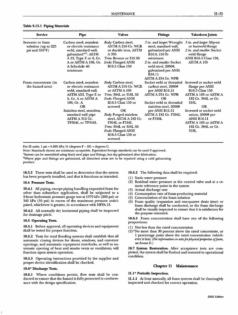
MAINTENANCE 11-35
Table 9.13.1 Piping Materials
Service Pipe Valves Fittings Takedown Joints
Seawater or foam solution (up to 225 psi and 350°F)
Carbon steel, seamless or electric resistance weld, standard wall, galvanizeda,b. ASTM A 53, Type E or S, Gr. A or ASTM A 106, Gr. A Schedule 40 minimum
Body: Carbon steel, ASTM A 216 Gr. WCB or ductile iron, ASTM A395
3 in. and larger: Wrought steel, standard wall, galvanized per ANSI BI6.9, 150 lb minimum
3 in. and larger: Slip-on or buttweld flange
2 in. and smaller: Socket weld flange
Trim: Bronze or 316 SS Ends: Flanged ANSI
B16.5 Class 150 2 in. and smaUer: Socket
weld steel, 2000#, galvanized per ANSI BI6.11
ANSI B16.5 Class 150, ASTMAI05
Foam concentrate (in the hazard area)
Carbon steel, seamless or electric resistance weld, standard wall. ASTM A53, Type E or S, Gr. A or ASTM A 106, Gr. A
Body: Carbon steel, ASTM A 216 Gr. WCB orASTMAI05
ASTM A 234 Gr. WPB Socket weld or threaded
carbon steel, 2000# per ANSI B16.11
ASTM A 234 Gr. WPB
Screwed or socket weld flange per ANSI B16.5 Class 150
ASTM A 105 or ASTM A 182 Gr. 304L or Gr. 316L
Trim: 304L or 316L SS Ends: Flanged ANSI
B16.5 Class 150 or OR
Socket weld or threaded stainless steel, 2000# per ANSI B16.11
ASTM A 182 Gr. F304L orF316L
OR screwed OR
OR Stainless steel, seamless,
standard wall pipe ASTM A 312 Gr. TP304L or TP316L
Body: Forged stainless steel, ASTM A 182 Gr. F304L or F316L
Screwed or socket weld union, 2000# per ANSIBI6.11
ASTM A 105 or ASTM A 182 Gr. 304L or Gr. 316L
Trim: 304L or 316L SS Ends: Flanged ANSI
B16.5 Class 150 or screwed
For SI units: 1 psi = 6.895 kPa; % (degrees F - 32) = degrees C. Note: Standards shown are minimum acceptable. Equivalent foreign standards can be used if approved. aSystem can be assembled using black steel pipe and fittings, hot dip galvanized after fabrication. ~ere pipe and fittings are galvanized, all disturbed areas are to be repaired using a cold galvanizing product.
10.3.2 These tests shall be used to determine that the system has been properly installed, and that it functions as intended.
10.4 Pressure Tests.
10.4.1 All piping, except piping handling expanded foam for other than subsurface application, shall be subjected to a 2-hour hydrostatic pressure gauge test at 1379 kPa (200 psi) or 345 kPa (50 psi) in excess of the maximum pressure anticipated, whichever is greater, in accordance with NFPA 13.
10.4.2 All normally dry horizontal piping shall be inspected for drainage pitch.
10.5 Operating Tests.
10.5.1 Before approval, all operating devices and equipment shall be tested for proper function.
10.5.2 Tests for total flooding systems shall establish that all automatic closing devices for doors, windows, and conveyor openings, and automatic equipment interlocks, as well as automatic opening of heat and smoke vents or ventilators, will function upon system operation.
10.5.3 Operating instructions provided by the supplier and proper device identification shall be checked.
10.6* Discharge Tests.
10.6.1 Where conditions permit, flow tests shall be conducted to ensure that the hazard is fully protected in conformance with the design specification.
10.6.2 The following data shall be required:
(1) Static water pressure (2) Residual water pressure at the control valve and at a re-
mote reference point in the system (3) Actual discharge rate (4) Consumption rate of foam-producing material (5) Concentration of the foam solution (6) Foam quality (expansion and on~uarter drain time) or
foam discharge shall be conducted, or the foam discharge shall be visually inspected to ensure that it is satisfactory for the purpose intended.
10.6.3 Foam concentration shall have one of the following proportions:
(1) Not less than the rated concentration (2)*No more than 30 percent above the rated concentrate, or
1 percentage point above the rated concentration (whichever is less) (Forinfonnation on tests forphysical properties offoam, see Annex D.)
10.7 System Restoration. Mter acceptance tests are completed, the system shall be flushed and restored to operational condition.
Chapter 11 Maintenance
11.1 * Periodic Inspection.
11.1.1 At least annually, all foam systems shall be thoroughly inspected and checked for correct operation.
2005 Edition

11-36 LOW-, MEDIUM-, AND HIGH-EXPANSION FOAM
11.1.2 The inspection shall include performance evaluation of the foam concentrate or premix solution quality or both.
11.1.3 Test results that deviate more than 10 percent from those recorded in acceptance testing shall be discussed immediately with the manufacturer.
11.1.4 The goal of this inspection and testing shall be to ensure that the system is in full operating condition and that it remains in that condition until the next inspection.
11.1.5 The inspection report, with recommendations, shall be filed with the owner.
11.1.6 Between the regular service contract inspections or tests, the system shall be inspected by competent personnel following an approved schedule.
11.2* Foam-Producing Equipment.
11.2.1 Proportioning devices, their accessory equipment, and foam makers shall be inspected.
11.2.2 Fixed discharge outlets equipped with frangible seals shall be provided with suitable inspection means to permit proper maintenance and for inspection and replacement of vapor seals.
11.3 Piping.
11.3.1 Aboveground piping shall be examined to determine its condition and to verify that proper drainage pitch is maintained.
11.3.2 Pressure tests of normally dry piping shall be made when visual inspection indicates questionable strength due to corrosion or mechanical damage.
11.3.3 Underground piping shall be spot-checked for deterioration at least every 5 years.
11.4 Strainers. Strainers shall be inspected periodically and shall be cleaned after each use and flow test.
11.5 Detection and Actuation Equipment. Control valves, including all automatic and manual-actuating devices, shall be tested at regular intervals.
11.6 Foam Concentrate Inspection.
11.6.1 At least annually, an inspection shall be made of foam concentrates and their tanks or storage containers for evidence of excessive sludging or deterioration.
11.6.2 Samples of concentrates shall be sent to the manufacturer or qualified laboratory for quality condition testing.
11.6.3 Quantity of concentrate in storage shall meet design requirements, and tanks or containers shall normally be kept full, with space allowed for expansion.
11.7 Operating Instructions and Training.
11.7.1 Operating and maintenance instructions and layouts shall be posted at control equipment with a second copy on file.
11.7.2 All persons who are expected to inspect, test, maintain, or operate foam-generating apparatus shall be thoroughly trained, and training shall be kept current over time.
2005 Edition
Annex A Explanatory Material
Annex A is not a part of the requirements of this NIPA document but is included for informational purposes only. This annex contains explanatory material, numbered to correspond with the applicable text paragraphs.
A.1.1 Fire-fighting foam is an aggregate of air-filled bubbles formed from aqueous solutions and is lower in density than flammable liquids. It is used principally to form a cohesive floating blanket on flammable and combustible liquids and prevents or extinguishes fire by excluding air and cooling the fuel. It also prevents reignition by suppressing formation of flammable vapors. It has the property of adhering to surfaces, which provides a degree of exposure protection from adjacent fires. Foam can be used as a fire prevention, control, or extinguishing agent for flammable liquid hazards. Foam for these hazards can be supplied by fixed piped systems or portable foam-generating systems. Foam can be applied through foam discharge outlets, which allow it to fall gently on the surface of the burning fuel. Foam can also be applied by portable hose streams using foam nozzles or large-capacity monitor nozzles or subsurface injection systems.
Foam can be supplied by overhead piped systems for protection of hazardous occupancies associated with potential flammable liquid spills in the proximity of high-value equipment or for protection oflarge areas. The foam used for flammable liquid spills is in the form of a spray or dense "snowstorm." The foam particles coalesce on the surface of the burning fuel after falling from the overhead foam outlets, which are spaced to cover the entire area at a uniform density. (For systems required to meet both foam and water spray design criteria, see NFPA 16.)
Large-spill flammable liquid fires can be fought with mobile equipment, such as an aircraft crash truck or industrial foam truck equipped with agent and equipment capable of generating large volumes offoam at high rates. Foam for this type of hazard can be delivered as a solid stream or in a dispersed pattern. Standards for industrial foam trucks include NFPA 1901, and standards for aircraft crash trucks include NFPA 414.
Foam does not break down readily and, when applied at an adequate rate, has the ability to extinguish fire progressively. As application continues, foam flows easily across the burning surface in the form ofa tight blanket, preventing reignition on the surfaces already extinguished. Foam is not suitable for three-dimensional flowing liquid fuel fires or for gas fires.
To determine where foam protection is required, see applicable standards such as NFPA 30. Foam can be applied to protect the surface of a flammable liquid that is not burning. The foam concentrate manufacturer should be consulted to determine the optimum method of application, rate of discharge, application density, and frequency of reapplication required to establish and maintain the integrity of the foam blanket.
A.3.2.1 Approved. The National Fire Protection Association does not approve, inspect, or certify any installations, procedures, equipment, or materials; nor does it approve or evaluate testing laboratories. In determining the acceptability of installations, procedures, equipment, or materials, the authority having jurisdiction may base acceptance on compliance with NFPA or other appropriate standards. In the absence of such standards, said authority may require evidence of proper installation, procedure, or use. The authority havingjurisdiction may also refer to the listings or labeling practices of an organization that is concerned with product evaluations and is thus in a position to determine compliance with appropriate standards for the current production of listed items.

ANNEXA 11-37
A.3.2.2 Authority HavingJurisdictiolll (AHJ). The phrase "authority having jurisdiction," or its acronym AHj, is used in NFPA documents in a broad manner, since jurisdictions and approval agencies vary, as do their responsibilities. Where public safety is primary, the authority havingjurisdiction may be a federal, state, local, or other regional department or individual such as a fire chief; fire marshal; chief of a fire prevention bureau, labor department, or health department; building official; electrical inspector; or others having statutory authority. For insurance purposes, an insurance inspection department, rating bureau, or other insurance company representative may be the authority having jurisdiction. In many circumstances, the property owner or his or her designated agent assumes the role of the authority having jurisdiction; at government installations, the commanding officer or departmental official may be the authority having jurisdiction.
A.3.2.4 Listed. The means for identifying listed equipment may vary for each organization concerned with product evaluation; some organizations do not recognize equipment as listed unless it is also labeled. The authority having jurisdiction should utilize the system employed by the listing organization to identify a listed product.
A.3.3.2 Concentration. The type of foam concentrate used determines the percentage of concentration required. For example, a 3 percent foam concentrate is mixed in the ratio of 97 parts water to 3 parts foam concentrate to make foam solution.
A.3.3.4.2 Non-Air-Aspirating Discharge Devices. When discharging AFFF or FFFP solution, they generate an effective AFFF or FFFP with a discharge pattern similar to the water discharge pattern.
A.3.3.6 Eductor (Inductor). An air foam hose nozzle with built-in eductor is the type of proportioner in which the jet in the foam maker is utilized to draft the concentrate (see Figure A.3.3.6). The bottom of the concentrate container should be not more than 1.8 m (6 ft) below the level of the foam maker. The length and size of hose or pipe between the concentrate container and the foam maker should conform to the recommendations of the manufacturer. Hydrocarbon surfactant-type foam concentrates are synthetic foaming agents generally based on a hydrocarbon surface active agent. They produce foams of widely different character (expansion and drainage times), depending on the type of foam-producing devices employed. In general, such foams do not provide the stability and burn-back resistance of protein-type foams or the rapid control and extinguishment ofAFFF, but they can be useful for petroleum-product spill fire fighting in accordance with their listings and approvals. There are hydrocarbon-base foaming agents that have been listed as foaming agents, wetting agents, or combination foaming/wetting agents. The appropriate listings should be consulted to determine correct application rates and methods.
A.3.3.6.1 In-Line Eductor. This eductor is used for installation in a hoseline, usually at some distance from the foam maker or playpipe, as a means of drafting air foam concentrate from a container. (See Figure A.3.3. 6 and Figure A.3.3. 6.1.)
The in-line eductor must be designed for the flow rate of the particular foam maker or playpipe with which it is to be used. The
device is very sensitive to downstream pressures and accordingly is designed for use with specified lengths of hose or pipe located between it and the foam maker.
The pressure drop across the eductor is approximately onethird of the inlet pressure.
The elevation of the bottom of the concentrate container should not be more than 1.8 m (6 ft) below the eductor.
FIGURE A.3.3.6 In-Line Edudor.
FlGURE A.3.3.6.1 Air Foam Hose Nozzle with Built-in Eductor.
2005 Edition
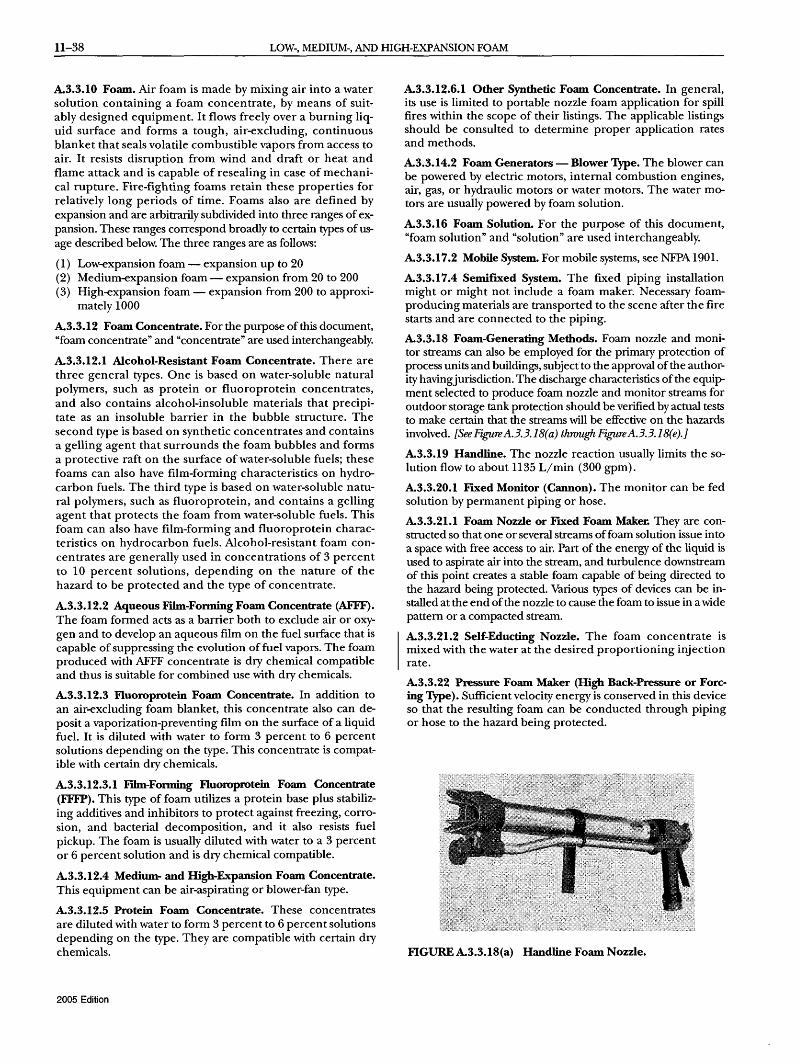
11-38 LOW-, MEDIUM-, AND HIGH-EXPANSION FOAM
A.3.3.10 Foam. Air foam is made by mixing air into a water solution containing a foam concentrate, by means of suitably designed equipment. It flows freely over a burning liquid surface and forms a tough, air-excluding, continuous blanket that seals volatile combustible vapors from access to air. It resists disruption from wind and draft or heat and flame attack and is capable of resealing in case of mechanical rupture. Fire-fighting foams retain these properties for relatively long periods of time. Foams also are defined by expansion and are arbitrarily subdivided into three ranges of expansion. These ranges correspond broadly to certain types of usage described below. The three ranges are as follows:
(1) Low-expansion foam - expansion up to 20 (2) Medium-expansion foam - expansion from 20 to 200 (3) High-expansion foam - expansion from 200 to approxi-
mately 1000
A.3.3.12 Foam Concentrate. For the purpose of this document, "foam concentrate" and "concentrate" are used interchangeably.
A.3.3.12.1 Alcohol-Resistant Foam Concentrate. There are three general types. One is based on water-soluble natural polymers, such as protein or fluoroprotein concentrates, and also contains alcohol-insoluble materials that precipitate as an insoluble barrier in the bubble structure. The second type is based on synthetic concentrates and contains a gelling agent that surrounds the foam bubbles and forms a protective raft on the surface of water-soluble fuels; these foams can also have film-forming characteristics on hydrocarbon fuels. The third type is based on water-soluble natural polymers, such as fluoroprotein, and contains a gelling agent that protects the foam from water-soluble fuels. This foam can also have film-forming and fluoroprotein characteristics on hydrocarbon fuels. Alcohol-resistant foam concentrates are generally used in concentrations of 3 percent to 10 percent solutions, depending on the nature of the hazard to be protected and the type of concentrate.
A.3.3.12.2 Aqueous Film-Forming Foam Concentrate (AFFF). The foam formed acts as a barrier both to exclude air or oxygen and to develop an aqueous film on the fuel surface that is capable of suppressing the evolution of fuel vapors. The foam produced with AFFF concentrate is dry chemical compatible and thus is suitable for combined use with dry chemicals.
A.3.3.12.3 Fluoroprotein Foam Concentrate. In addition to an air-excluding foam blanket, this concentrate also can deposit a vaporization-preventing film on the surface of a liquid fuel. It is diluted with water to form 3 percent to 6 percent solutions depending on the type. This concentrate is compatible with certain dry chemicals.
A.3.3.12.3.1 Fdm-Fonning Ftuoroprotein Foam Concentrate (FFFP). This type of foam utilizes a protein base plus stabilizing additives and inhibitors to protect against freezing, corrosion, and bacterial decomposition, and it also resists fuel pickup. The foam is usually diluted with water to a 3 percent or 6 percent solution and is dry chemical compatible.
A.3.3.12.4 Medium- and High-Expansion Foam Concentrate. This equipment can be air-aspirating or blower-fan type.
A.3.3.12.5 Protein Foam Concentrate. These concentrates are diluted with water to form 3 percent to 6 percent solutions depending on the type. They are compatible with certain dry chemicals.
2005 Edition
A.3.3.12.6.1 Other Synthetic Foam Concentrate. In general, its use is limited to portable nozzle foam application for spill fires within the scope of their listings. The applicable listings should be consulted to determine proper application rates and methods.
A.3.3.14.2 Foam Generators - Blower Type. The blower can be powered by electric motors, internal combustion engines, air, gas, or hydraulic motors or water motors. The water motors are usually powered by foam solution.
A.3.3.16 Foam Solution. For the purpose of this document, "foam solution" and "solution" are used interchangeably.
A.3.3.17.2 Mobile System. For mobile systems, see NFPA 1901.
A.3.3.17.4 Semifixed System. The fixed piping installation might or might not include a foam maker. Necessary foamproducing materials are transported to the scene after the fire starts and are connected to the piping.
A.3.3.18 Foam-Generating Methods. Foam nozzle and monitor streams can also be employed for the primary protection of process units and buildings, subject to the approval of the authority havingjurisdiction. The discharge characteristics of the equipment selected to produce foam nozzle and monitor streams for outdoor storage tank protection should be verified by actual tests to make certain that the streams will be effective on the hazards involved. [See Figure A.3.3.18( a) thwugh Figure A.3.3.18( e). ]
A.3.3.19 Handline. The nozzle reaction usually limits the solution flow to about 1135 L/min (300 gpm).
A.3.3.20.1 Fixed Monitor (Cannon). The monitor can be fed solution by permanent piping or hose.
A.3.3.21.1 Foam Nozzle or FIXed Foam Maker. They are constructed so that one or several streams of foam solution issue into a space with free access to air. Part of the energy of the liquid is used to aspirate air into the stream, and turbulence downstream of this point creates a stable foam capable of being directed to the hazard being protected. Various types of devices can be installed at the end of the nozzle to cause the foam to issue in a wide pattern or a compacted stream.
A.3.3.21.2 Self-Educting Nozzle. The foam concentrate is mixed with the water at the desired proportioning injection rate.
A.3.3.22 Pressure Foam Maker (High Back-Pressure or Forcing Type). Sufficient velocity energy is conserved in this device so that the resulting foam can be conducted through piping or hose to the hazard being protected.
FIGURE A.3.3.18(a) Handline Foam Nozzle.

ANNEXA 11-39
FIGURE A.3.3.18(b) Adjustable Straight Stream-to-Fan Pattern Foam-Water Monitor.
FIGURE A.3.3.18(c) Adjustable Straight Stream-to-Spray Foam-Water Monitor.
FIGUREA.3.3.18(d) Wheeled Portable Foam-Water Monitor.
FIGURE A.3.3.18(e) Portable Foam-Water Monitor.
A.3.3.23 Pressure Proportioning Tank. This method employs water pressure as the source of power. With this device, the water supply pressurizes the foam concentrate storage tank. At the same time, water flowing through an adjacent venturi or orifice creates a pressure differential. The low-pressure area of the venturi is connected to the foam concentrate tank, so that the difference between the water supply pressure and this low-pressure area forces the foam concentrate through a metering orifice and into the venturi. Also, the differential across the venturi varies in proportion to the flow, so one venturi will proportion properly over a wide flow range. The pressure drop through this unit is relatively low. [See Figure A.3.3.23( a).J
A special test procedure is available to permit the use of a minimum amount of concentrate when the pressure proportioner system is testing.
The pressure proportioning tank has the following limitations:
(1) Foam concentrates with specific gravities similar to water can create a problem when mixed.
(2) The capacity of these proportioners can be varied from approximately 50 percent to 200 percent of their rated capacity.
(3) The pressure drop across the proportioner ranges from 34 kPa to 207 kPa (5 psi to 30 psi), depending on the volume of water flowing within the capacity limits of item (2) above.
(4) When the concentrate is exhausted, the system must be turned off, and the tank drained of water and refilled with foam concentrate.
(5) Since water enters the tank as the foam concentrate is discharged, the concentrate supply cannot be replenished during operation, as with other methods.
(6) This system proportions at a significantly reduced percentage at low flow rates and should not be used below minimum design flow rate.
A diaphragm (bladder) pressure proportioning tank also uses water pressure as a source of power. This device incorporates all the advantages of the pressure proportioning tank with the added advantage of a collapsible diaphragm that physically separates the foam concentrate from the water supply.
2005 Edition

11-40 LOW-, MEDIUM-, AND HIGH-EXPANSION FOAM
Water supply
Note: Schematic diagram for clarity only. Does not necessarily show all required valves.
PPH operating head
Water bypass (if desired)
FIGURE A.3.3.23(a) Typical Arrangement of Pressure Pr0-portioning Tank.
Diaphragm pressure proportioning tanks operate through a similar range of water flows and according to the same principles as pressure proportioning tanks. The added design feature is a reinforced elastomeric diaphragm (bladder) that can be used with all concentrates listed for use with that particular diaphragm (bladder) material. [SeeFigureA.3.3.23(b).j
The proportioner is a modified venturi device with a foam concentrate feed line from the diaphragm tank connected to the low-pressure area of the venturi. Water under pressure passes through the controller, and part of this flow is diverted into the water feed line to the diaphragm tank. This water pressurizes the tank, forcing the diaphragm filled with foam concentrate to slowly collapse. This forces the foam concentrate out through the foam concentrate feed line and into the low-pressure area of the
Alternate proportioner location ~
Sight gauge
proportioner controller. The concentrate is metered by use of an orifice or metering valve and mixes in the proper proportion with the main water supply, sending the correct foam solution downstream to the foam makers.
The limitations are the same as those listed above for the pressure proportioning tank, except that the system can be used for all types of concentrates.
A.3.3.25.1 Balanced Pressure Pump-Type Proportioning. By means of an auxiliary pump, foam compound is injected into the water stream passing through an inductor. The resulting foam solution is then delivered to a foam maker or playpipe. The pnr portioner can be inserted into the line at any point between the water source and foam maker or playpipe. (See Figure A. 3.3. 25. 1.) To operate, the main water valve is opened and a reading of the pressure indicated on the duplex gauge is taken. When both gauge hands are set at the same point, the correct amount of foam concentrate is being injected into the water stream. This reading is done automatically by the use of a differential pressure diaphragm valve.
Metered proportioning has the following limitations:
(1) The capacity of the proportioner can be varied from approximately 50 percent to 200 percent of its rated capacity.
(2) The pressure drop across the proportioner ranges from 34 kPa to 207 kPa (5 psi to 30 psi), depending on the volume of water flowing through the proportioner within the capacitylimits of item (1) above.
(3) A separate pump is needed to deliver concentrate to the proportioner.
A.3.3.25.1.1 In-Line Balanced Pressure Proportioning. A bladder tank in conjunction with a water pressure-reducing valve upstream of the proportioner can be utilized in place of the foam concentrate pump package. See Figure A3.3.25.1.1(a) and Figure A3.3.25.1.1 (b).
Internal bladder
Pressure vessel
Water supply
Foam solution
Foam concentrate line
Ball valve
Swing check valve
Foam concentrate line Motorized valve (optional)
Note: A motorized foam concentrate valve permits the activation of this system
Proportioning controller
from any remote signaling source.
FIGURE A.3.3.23(b) Diaphragm (Bladder) Proportioning Tank.
2005 Edition
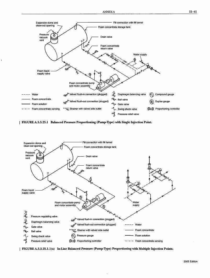
Expansion dome and clean-out opening
Water
vacuum vent
Foam concentrate
Foam solution
Foam concentrate sensing
ANNEXA
Fill connection with fill funnel
Drain valve
Foam concentrate return valve
~" Water supply , " \ ',<~~ /~ ~
~~ ;. ,,,. ',- .,,,- -
~ Valved flush-in connection (plugged) ~ Diaphragm balancing valve @ ~ Valved flush-out connection (plugged)
~ Ball valve
® ~ Gate valve
~ Strainer with valved side outlet "\" Swing check valve ~
1> Pressure relief valve
Compound gauge
Duplex gauge
Proportioning controller
I FIGUREA.3.3.25.1 Balanced Pressure Proportioning (Pump-Type) with Single Injection Point.
Expansion dome and
clean-out ~ng ')
Pressure I vacuum vent
Pressure regulating valve
Diaphragm balancing valve
Gate valve
Ball valve
Swing check valve
Pressure relief valve
r------ Fill connection with fill funnel
Drain valve
Foam concentrate return valve
~ Valved flush-in connection (plugged)
~ Valved flush-out connection (plugged)
~ Strainer with valved side outlet
@ Pressure gauge
~ Proportioning controller
Water
Foam concentrate
Foam solution
Foam concentrate sensing
I FIGURE A.3.3.25.1.1 (a) In-Line Ballanced Pressure (Pump-Type) Proportioning with Multiple Injection Points.
11-41
2005 Edition

11-42 LOW-, MEDIUM-, AND HIGH-EXPANSION FOAM
'1 ,/' '1 Preaction
~lIating monitor
~, -- ~ / To system,
discharge .+ ''''''''''''',- /' Q sprinkler
~ ~, y system ,/ "'" '
Concentrate controller ~ ' ............ ' / 'j 3-way Balancing
,/ ..... ,'- /' solenoid valve Metering ~ X valve ~rifice
0/' , ~Foam V/ ""- pressure
To system"1 I inlet ' discharge I I ~ ~ ,<.
• Automatic I .... ~ Check l, /' Concentrate' foam valve
Release
controller valve 2-way ~ control panel 3
-way Balancing solenoid valve Metering
valve ~rifice
I solenoid I valve " ,/) Foam
pressure inlet <
.... ~heckl,/'
,
9 Check I valve
,
.. Needling~ valves
I
t l'
,
9Check I valve
,
,I Pilot regulator
valve 2-way
, solenoid " valve
,/)
~Pt
I
I Pilot 'regulator
I i ,/, Foam*
i ./ X Wate,
l ' >,? I ?' "1 ,~,/ ,/:Setat 6.fH3.6 bar
Foam • t ,/ ,/ or 1.7-2.1 bar concentrate '/1 Foam / / (100-125 psi or
Foam .;r ~i,\-, 'I' / /' /' 25-30 psi) lower bladder ,/' \':Jf;;) 'I 1/" /' Water /' than foam pressure
tank / 'Of(} ~ '. X' ,,/ inlet.at riser during , \f;;)'? -9/'1 'I I '/'/ maximum flow
/ ' , ~ ~' condition , 'I " ~ ;r(',Y
'- ' , ,/ , '"'" ~0.3 bar (150 psi)
'~~ / , Balancing 1,~ater;JY'
Supply I "'" yalve '"'" ~
"~'~~'-'~''-' /,/,K'>'
I ,/' Fire ,i ~gUlat.or set at.9.7-12.1 bar
pump ",~ ~~O pSI-175 pSI)
FIGURE A3.3.25.1.1 (b) In-Line Balanced Pressure (Bladder Tank Type) Proportioning with Multiple Injection Points.
A3.3.25.2 Direct Injection Variable Pump Output Proportioning. Direct injection foam proportioning systems utilize a foam concentrate pump to inject foam concentrate directly into the water stream. Foam proportioning system operation is not affected by water pressure or interrupted while the foam concentrate tank is refIlled. Direct injection foam proportioning systems are generally automatic regulation proportioning systems. Automatic flow-sensing direct injection foam proportioning systems utilize an in-line flowmeter(s) to monitor the system operating conditions. System operating data is transmitted to an electronic control, which controls the foam pump output to maintain the desired proportioning ratio. The following two different flow sensing systems are available:
2005 Edition
(1) An electronic control receives electronic signals corresponding to the proportioning ratio from the control panel and water flow data from the flowmeter. The electronic control then commands the foam concentrate pump module to deliver foam concentrate at the proportional rate. [See Figure A.3.3. 25. 2( a)).
(2) An electronic control receives electronic signals corresponding to the foam concentrate flow from a foam concentrate flowmeter, the proportioning ratio from the control panel, and water flow data from the water flowmeter. The electronic control controls the proportioning ratio through a foam concentrate metering valve shown in Figure A.3.3.25.2(b). In a water motor

ANNEXA 11-43
foam proportioning system, a water motor drives a positive displacement foam concentrate pump. The water motor can be of either a positive displacement type or a turbine type. Water motor foam proportioning systems are automatic regulating proportioning systems. Where a positive displacement water motor drives the foam concentrate pump, the ratio of the water motor displacement to the displacement of the foam concentrate pump is the ratio of the desired foam solution. A positive displacement water motor proportioning system requires no external power. [See Figure A.3.3.25.2( c)}.
A water turbine-driven foam proportioning system uses a water turbine to power a positive displacement foam concentrate pump. Flowmeters sense the foam concentrate pump output and the water flow, sending signals to an electronic control that controls the proportioning ratio by adjusting the water turbine speed. [SeeFigureA.3.3.25.2(d)}.
Pressure vacuum vent
Display
1
___ ~ Electronic -$ control
i ~ 'T'"
1>-----' .-- 1
~/ Pressure gauge
~L .t!" - -'F) Water pump Flowmeter 't"
Water/foam :.... - - --0 Compound discharge ~ gauge
4,uction
Foam concentrate
Water
Hydraulic
Electric
FIGURE .A.3.3.25.2(a) Single-Meter Flow-Sensing Direct Injection Foam Proportioning System.
.A.3.3.27 Pump Proportioner (Around-the-Pump Proportioner). This device consists of an eductor installed in a bypass line between the discharge and suction of a water pump. A small portion of the discharge of the pump flows through this eductor and draws the required quantity of air foam concentrate from a container, delivering the mixture to the pump suction. Variable capacity can be secured by the use of a manually controlled multiported metering valve. [See Figure A.5.2. 6.1 (a).}
A pump proportioner has the following limitations:
(1) The pressure on the water suction line at the pump must be essentially zero gauge pressure or must be on the vacuum side. A small positive pressure at the pump suction can cause a reduction in the quantity of concentrate educted or cause the flow of water back through the eductor into the concentrate container.
(2) The elevation of the bottom of the concentrate container should not be more than 6 ft (1.8 m) below the proportioner.
Electric metering valve
~w meter /" +- Tank fill
Electronic : __ *J 1
II «) Pre'Ssure-: + 1 gauge
1F)water Flowm:t;'r't' pump
Water/foam :.. ---0 discharge ~ T
/ Compound Water suction gauge
Pressure vacuum vent
Concentrate tank
Tank drain
Tank shutoff
'-Concentrate inlet
Foam concentrate
Water
Hydraulic
Electric
FIGURE .A.3.3.25.2(b) Dual-Meter Flow-Sensing Direct Injection Foam Proportioning System.
Pressure vacuum vent
Concentrate pump~
(.
.. 0 Pressure gauge
[ , .. ".;- -! - -~ --~ Water pump
Water/foam L \, 1
discharge Water motor r --0 1 Compound gauge
4.:er suction
Foam concentrate
Water
FIGURE .A.3.3.25.2(c) Water Motor Foam Proportioning System.
(3) The bypass stream to the proportioner uses from 38 L/min to 151 L/min (10 gpm to 40 gpm) of water depending on the size of the device and on the pump discharge pressure. This factor must be recognized in determining the net delivery of the water pump.
The foam trough shown schematically in Figure A3.3.27 (b) consists of sections of steel sheet formed into a chute that is securely attached to the inside of the tank wall so that it forms a descending spiral from the top of the tank to within 1.2 m (4 ft) of the bottom. [SeeFigureA.3.3.27(a) andFigureA.3.3.27(c).}
2005 Edition

11-44 LOW-, MEDIUM-, AND HIGH-EXPANSION FOAM
Pressure vacuum vent
Flowmeter .-. -. Tank fill Concentrate r---~~-------r-------'~-; tank
Foam concentrate
Water
Electric
FlGURE A.3.3.25.2(d) Water Turbine-Driven Flow-Sensing Direct Injection Foam Proportioning System.
Solution discharge line
Water suction line
Metering valve
FlGURE A.3.3.27 (a) Around-the-Pump Proportioner.
FlGUREA.3.3.27(b) Foam Trough.
2005 Edition
0.6 m (2 ft) (min) . 1.2 m (4 ft) (max) Pipe support
\ . Drain at low point
Roadway \... Extend pipe through firewall to edge of road
FlGURE A.3.3.27(c) Typical Air Foam Piping for Intermediate Back-Pressure Foam System.
In Figure A3.3.27(c), note that one brace [13 mm (lh in.) plate, 305 mm (12 in.) long] should be provided at each shell course. This brace helps maintain the shell in place during the early stages of the fire and prevents buckling before cooling water is applied.
A.4.1 A foam system consists of a water supply, a foam concentrate supply, proportioning equipment, a piping system, foam makers, and discharge devices designed to distribute foam effectively over the hazard. Some systems include detection devices.
A.4.2.1.2 Additional water supplies are recommended for cooling the hot tank shell to assist the foam in sealing against the shell. Some foams are susceptible to breakdown and failure to seal as a result of heating the tank shell due to prolonged burning prior to agent discharge.
A.4.2.1.4 Higher or lower water temperatures can reduce foam efficiency.
A.4.3.1.2 Some concentrates are suitable for use both on hydrocarbon fuels and on water-miscible or polar fuels and solvents.
A.4.3.2.2 The level of concentrate in the storage tank should be monitored to ensure that an adequate supply is available at all times. The hazard requiring the largest foam solution flow rate does not necessarily dictate the total amount of foam concentrate required. For example, a Class II product tank requiring a flow of 1136 L/ min (300 gpm) foam solution for 30 minutes would require 1022 L (270 gal) of 3 percent concentrate. A Class I product tank requiring a flow of 946 L/min (250 gpm) foam solution for 55 minutes would require 1563 L (412.5 gal) of 3 percent concentration.
A.4.3.2.4.1 Since such systems might or might not be operated for long periods after installation, the choice of proper storage conditions and maintenance methods largely determines the reliability and the degree of excellence of system operation when they are put into service.
A.4.3.2.4.2 Foam concentrates are subject to freezing and to deterioration from prolonged storage at high temperatures. The storage temperature should be monitored to ensure that

ANNEXA 11-45
listed temperature limitations are not exceeded. Concentrates can be stored in the containers in which they are transported or can be transferred into large bulk storage tanks, depending on the requirements of the system. The location of stored containers requires special consideration to protect against exterior deterioration due to rusting or other causes. Bulk storage containers also require special design consideration to minimize the liquid surface in contact with air.
A.4.4. 1. 1 Often, different brands of the same type of foam concentrates are found to be chemically compatible. However, before different brands of concentrates are mixed for long-term storage, evaluations should be made to determine such compatibility. A number of parameters should be considered and evaluated before concentrates are mixed for storage. In addition to the chemical compatibility, one should consider effects on proportioning and discharge hardware (many listings and approvals are very specific with regard to operating pressures, flow ranges, and materials of construction of hardware components). The application method should be the same for both foams being mixed. The system design application rate (density) might have to be changed if one of the foam concentrates being admixed is listed or approved at an application rate (density) that is higher than the one used for the initial design. This generally applies to alcohol-resistant foams since their listings and approvals are very application rate sensitive.
A.4.4.2 Some expanded foam is not compatible with all dry chemical agents.
A.4.6 Foam concentrate pumps are generally of the positive displacement variety. Centrifugal pumps might not be suitable for use with foam concentrates exhibiting high-viscosity characteristics. The foam equipment manufacturer should be consulted for guidance.
A.4.7.2.1 Corrosive atmospheres could require other coatings.
A.4.7.3.5 Corrosive atmospheres could require other coatings.
A.4.7.4.3 Welding is preferable where it can be done without introducing fire hazards.
A.4.7.6 A hazard area generally includes all areas within dikes and within 15 m (50 ft) of tanks without dikes. Other areas that should be considered hazard areas include the following:
(1) Locations more than 15 m (50 ft) from tanks without dikes, if the ground slope allows exposure from accidentally released flammable and combustible liquids
(2) Extensive manifold areas where flammable and combustible liquids might be released accidentally
(3) Other similar areas
The presence of flammable and combustible liquids within pipelines that do not possess the potential to release flammable and combustible liquids should not be considered as creating a hazard area. Ball valves can be used for foam concentrate proportioning systems.
A.4.9.2.5 See applicable sections of NFPA 72.
A.4.9.2.6 See Article 500 and other articles in Chapter 5 of NFPA70.
A.5.1 There have been cases reported where the application of foam through solid streams that were plunged into the flammable liquid has been believed to be the source ofignition of the ensuing fire. The ignitions have been attributed to static discharges resulting from splashing and turbulence. Therefore, any
application of foam to an unignited flammable liquid should be as gentle as possible. Correct application methods with portable equipment might include a spray pattern or banking the foam stream off a backboard so that the foam flows gently onto the liquid surface. Also, correctly designed fixed foam chambers on tanks could be expected to deliver the foam fairly gently and not cause a problem. Covered (internal) floating roof tanks can experience two distinct types of fires: a full surface area fire (as a result of the floating roof sinking) or a seal fire. There have been few fires in double-deck or pontoon-type floating roof tanks where fixed roofs and venting are designed in accordance with NFPA 30. Prior to selecting the method of protection, the type of fire that will serve as the basis for design should be defined.
Outdoor Fixed-Roof (Cone) Tanks. Within the scope of this standard, fixed-roof (cone) tanks are defined as vertical cylindrical tanks with a fixed roof designed as a conical section, and they comply with the requirements set forth in NFPA 30. Typically, these tanks have a weak seam at the junction of the vertical side and roof. In the event of an internal explosion, the seam usually parts and the roof blows off, leaving the shell intact to retain the tank contents. The resulting fire involves the entire exposed surface of the product.
These systems are used for the protection of outdoor process and storage tanks. They include the protection of such hazards in manufacturing plants as well as in large tank farms, oil refineries, and chemical plants. These systems usually are designed for manual operation but, in whole or in part, can be automatic in operation. Foam systems are the preferred protection for large outdoor tanks of flammable liquids, as shown in Figure A5.I.
Foam made here at chambers Foam chamber
FlGURE A.5.1 Schematic Arrangement of Air Foam Protection for Storage Tanks.
A.5.2.3 The requirements provided in this section are based on extrapolations of test experience and appropriate listings and reflect the limitations known to date. Foam can fail to seal against the tank shell as a resul t of prolonged free burning prior to agen t discharge. If adequate water supplies are available, cooling of the tank shell is recommended. Where the entire liquid surface has been involved, fires in tanks up to 39 m (150 ft) in diameter have been extinguished with large-capacity foam monitors. Depending on the fixed-roof tank outage and fire intensity, the updraft due to chimney effect can prevent sufficient foam from reaching the burning liquid surface to form a blanket. Foam should be applied continuously and evenly. Preferably, it should be directed against the inner tank shell so that it flows gently onto the burning liquid surface without undue submergence. This can be difficult to accomplish, as adverse winds, depending on velocity and
2005 Edition

11-46 LOW-, MEDIUM-, AND HIGH-EXPANSION FOAM
direction, reduce the effectiveness of the foam stream. Fires in fixed-roof tanks with ruptured roofs that have only limited access for foam application are not easily extinguished by monitor application from ground level. Fixed foam monitors can be installed for protection of drum storage areas or diked areas.
A.5.2.4.2.1 The specified minimum delivery rate for primary protection is based on the assumption that all the foam reaches the area being protected.
A.5.2.4.2.2 Where protection is desired for hydrocarbons having a flash point above 93.3°C (200°F), a minimum discharge time of 35 minutes should be used.
A.5.2.4.3 When some older types of alcohol-resistant foam concentrate are used, consideration should be given to solution transit time. Solution transit time (i.e., the elapsed time between injection of the foam concentrate into the water and the induction of air) might be limited, depending on the characteristics of the foam concentrate, the water temperature, and the nature of the hazard protected. The maximum solution transit time of each specific installation should be within the limits established by the manufacturer.
A.5.2.4.3.1 In general, alcohol-resistant foams can be effectively applied through foam monitor or foam hose streams to spill fires of these liquids where the liquid depth does not exceed 25.4 mm (1 in.).
A.5.2.4.3.2 If application results in foam submergence, the performance of alcohol-resistant foams usually deteriorates significantly, particularly where there is a substantial depth offuel. The degree of performance deterioration depends on the degree of water solubility of the fuel (Le., the more soluble, the greater the deterioration) .
A.5.2.5.1 For this application, discharge outlets are commonly called foam chambers. Most foam chambers are of a Type II discharge outlet design, since they are normally suitable for use with modern foams.
A.5.2.5.2.1 It is recommended that, for tanks greater than 60 m (200 ft) in diameter, at least one additional discharge outlet should be added for each additional 465 m2 (5000 ft2) of liquid surface or fractional part thereof. Since there has been limited experience with foam application to fires in fixed-roof tanks greater than 42 m (140 ft) in diameter, requirements for foam protection on such tanks are based on the extrapolation of data from successful extinguishments in smaller tanks. Tests have shown that foam can travel effectively across at least 30 m (100 ft) of burning liquid surface. On fixed-roof tanks of over 60 m (200 ft) diameter, subsurface injection can be used to reduce foam travel distances for tanks containing hydrocarbons only. Unless subsurface foam injection is utilized, a properly sized flanged connection should be installed on all atmospheric pressure storage tanks, regardless of present intended service, to facilitate the future installation of an approved discharge outlet if a change in service should require such installation. Figure A.5.2.5.2.1 (a) and Figure A.5.2.5.2.1 (b) are typical fixed foam discharge outlets or foam chambers.
A.5.2.5.2.2 Where protection is desired for hydrocarbons having a flash point above 93.3°C (200°F), a minimum time of 15 minutes for Type I outlets and 25 minutes for Type II outlets should be used.
2005 Edition
F1GURE A.5.2.5.2.1(a) Air Foam Maker in Horizontal Position at Top of Storage Tank.
FIGURE A.5.2.5.2.1 (b) Foam Chamber and Foam Maker.
A.5.2.5.3 The system should be designed based on fighting a fire in one tank at a time. The rate of application for which the system is designed should be the rate computed for the protected tank considering both the liquid surface area and the type of flammable liquid stored. For example, the property contains a 12.2 m (40 ft) diameter tank storing ethyl alcohol and 10.7 m (35 ft) diameter tank storing isopropyl ether. The liquid surface area of a 12.2 m (40 ft) diameter tank equals 116.8 m2 (1257 ft2). Assuming the solution rate for ethyl alcohol is 4.1 L/min·m2 (0.1 gpm/ft2), then 1257 gpm/ft2 x 0.1 = 477 L/min (126 gpm). The liquid surface area of a 10.7 m (35 ft) diameter tank equals 89.4 m2 (962 ft2).

ANNEXA 11-47
Assuming the solution rate for isopropyl ether is 6.1 L/ min·m2 (0.15 gpm/ fr), then 962 rr x 0.15 gpm/ft2 = 144 gpm. For SI units: Solution rate = 89.4 x 6.1 = 545 L/min. In this example, the smaller tanks storing the more volatile product require the higher foam-generating capacity. In applying this requirement, due consideration should be given to the future possibility of change to a more hazardous service requiring greater rates of application. Unfinished solvents or those of technical grade can contain quantities of impurities or diluents. The proper rate of application for these, as well as for mixed solvents, should be selected with due regard to the foam-breaking properties of the mixture.
A.5.2.5.3.2 Systems using these foams require special engineering consideration.
A.5.2.6.1 Experience with fuel storage tank fire fighting has shown that the main problems are operational (i.e., difficulty in delivering the foam relatively gently to the fuel surface at an application rate sufficient to effect extinguishment). A properly engineered and installed subsurface foam system offers the potential advantages of less chance for foam-generation equipment disruption as a result of an initial tank explosion or the presence of fire surrounding the tank, and the ability to conduct operations a safe distance from the tank. Thus, the opportunity for establishing and maintaining an adequate foam application rate is enhanced. The following guidelines regarding fire attack are recommended. Mter necessary suction connections are made to the water supply and foammaker connections are made to foam lines, foam pumping operations should be initiated simultaneously with opening of block valves permitting the start of foam flow to the tank. Solution pressure should be brought up to and maintained at design pressure.
When foam first reaches the burning liquid surface, there can be a momentary increase in intensity caused by the mechanical action of steam formation when the first foam contacts the heat of the fire. Initial flame reduction and reduction of heat is then usually quite rapid, and gradual reduction in flame height and intensity will occur as the foam closes in against the tank shell and over the turbulent areas over foam injection points. If sufficient water supplies are available, cooling of the tank shell at and above the liquid level will enhance extinguishment and should be used. Care should be taken
that water streams are not directed into the tank where they could disrupt the established foam blanket. Mter the fire has been substantially extinguished by the foam, some fire can remain over the point of injection. With flash points below 37.8°C (lOO°F) (Class IB and Class IC liquids), the fire over the turbulent area will continue until it is adequately covered by foam. With gasoline or equivalent liquids, when fire remains only over the area of injection, intermittent injection should be used so that foam will retrogress over the area during the time foam injection is stopped. Depending on local circumstances, it might be possible to extinguish any residual flickers over the turbulent area with portable equipment rather than continue the relatively high rate of application to the whole tank. If the tank contains a burning liquid capable of forming a heat wave, a slop-over can occur from either topside or subsurface injection of foam, especially if the tank has been burning for 10 minutes or longer. Slop-over can be controlled by intermittent foam injection or reduction in foammaker inlet pressure until slop-over ceases. Once slop-over has subsided, and in the case of liquids that do not form a heat wave, the pump rate should be continuous. FigureA.5.2.6.1 (a) and Figure A.5.2.6.1(b) illustrate typical arrangements of semifIxed subsurface systems.
Product ---il~ line
FlGURE A.5.2.6.1 (a) Semifixed Subsurface Foam Installation.
Portable high back-pressure foam maker for subsurface application
\ ~5 mm (2% in.) \,e hose thread
cD Lpte, inlet swivel
65 mm (2% in.)
Foam ~
flow
FlGURE A.5.2.6.1 (b) Typical Connection for Portable High Back-Pressure Foam Maker for Subsurface Application in Semifixed System.
2005 Edition

11-48 LOW-, MEDIUM-, AND HIGH-EXPANSION FOAM
A.5.2.6.2 Figure A5.2.6.2(a) through Figure A5.2.6.2(c) should be used to determine foam velocity.
Expanded foam velocity also can be calculated by using the following formulas:
v = gpm ~oam x 0.4085 d
where: d = pipe ID (in.)
E Ii h I . (£i / ) Expanded foam (gpm) ng s ve OClty t sec = -':""'---KA--";':::':"---'- .. L/minfoam Metnc VelOCIty (m/sec) = 2 x 21.22
where: A = area of ID of the injection pipe (ft2)
K = constant 449
d
where: d = pipe ID (mm)
gpm = gallons per minute or
Figure A5.2.6.2(d) illustrates optional arrangements for multiple subsurface discharge outlets.
~ ·u o ~
o 0 Q) Q)
~ ~
12.2 40
9.1 30 I---+-++--I--+_---+-+---t---I---~"I_--+_--_+--__:I
E CCI & 6.1 20 1---t-I'--f---~~--+--7"'i---I---__:::~'---+_-___:__.
Umin gpm
o~----~----~----~----~------~----~----~----~----~ 3028 800
6056 1600
9084 2400
12,111 15,139 18,167 21,195 24,223 27,251 3200 4000 4800 5600 6400 7200
Expanded foam rate
FIGURE A.5.2.6.2(a) Foam Velocity vs. Pipe Size (21;2 in., 3 in., 4 in., 6 in., 8 in., 10 in., 12 in., and 14 in.) - Standard Schedule 40 Pipe.
o 0 Q) Q)
~ ~ 9.1 30 r------~----"""T'"------,------~-----,----__r"7"'"--___,r__----~---..,
~ 6.1 20 1----+----I----II----+7'I!::...---+---,:::ooo,c....-+---=JIIIIII!!=I----+---~ ·u o ~ E CCI
~ 3 10 ~--+---~I!::...-~~~JIIIIII!!=~+---~----+--~I----+----~
Umin gpm
o ~----~----~----~------~---~---~----~~----~---~ 7570 2000
15,139 22,710 30,278 37,848 45,420 52,990 60,560 4000 6000 8000 10,000 12,000 14,000 16,000
Expanded foam rate
FIGUREA.5.2.6.2(b) Foam Velocityvs. Pipe Size (14 in., 16 in., and 18 in.) - Standard Schedule 40 Pipe.
2005 Edition

ANNEXA 11-49
o 0 Q) Q)
~ ~ 9.1 30~--~----~----~--~-----r----~~~
~
·g6.1 20~--~-----+----~--~~~--~--~~~~
~
~ LL. 3.1 10 t-----t-----7'''''----::2o'''"''''""-----+-----t-----f-------1
Umin gpm
o~ __ ~ ____ ~ ____ ~ ____ ~ ____ ~ __ ~ ____ ~ 15,139 30,280 45,420 60,560 75,696 90,840 105,980 4000 8000 12,000 16,000 20,000 24,000 28,000
Expanded foam rate
FIGURE A.5.2.6.2(c) Foam Velocity vs. Pipe Size (20 in. and 24 in.) - Standard Schedule 40 Pipe.
Connections for subsurface foam makers
~-+-=--------I>4-C. j/ Valved : test
Rupture disc connection (optional)
Dikewall~
FIGURE A.5.2.6.2(d) Typical Arrangement of Semifixed Subsurface System.
A.5.2.6.3 Figure A5.2.6.3 illustrates a typical foam inlet tank connection.
A.5.2.6.3.1 Liquid hydrocarbons that contain foam-destructive products might require higher application rates. Some foams might fail to extinguish fires in gasolines containing oxygenates where subsurface discharge is used at the usually required rate. Optimum fluoroprotein foam,AFFF, and FFFP characteristics for subsurface injection purposes should have expansion ratios between 2 and 4. fSee Figure A. 5. 2. 6.3. 1 (a) and FigureA.5.2. 6.3. 1 (b).}
A.5.2.6.4 The back pressure consists of the static head plus pipe friction losses between the foam maker and the foam inlet to the tank. The friction loss CUIVes, as shown in FigureA5.2.6.4(a) and Figure A5.2.6.4(b), are based on a maximum foam expansion of 4, which is the value to be used for friction loss and inlet velocity calculations.
Swing Rupture disc check (optional) valve
~
Foam
flow
W~~:zI'-r-- At least 0.3 m (1 ft)
• water bottom
FIGURE A.5.2.6.3 Typical Tank Foam-Maker Discharge Connection for Subsurface Injection.
A.5.2.6.5.2 Liquid hydrocarbons that contain foam-destructive products might require higher application rates. Some foams might fail to extinguish fires in gasolines containing oxygenates where subsurface discharge is used at the usually required rate.
A.5.2.7 This section describes the design criteria that are applicable to systems used to apply foam to the surface of fixedroof (cone) storage tanks via a flexible hose rising from the base of the tank. Manufacturer recommendations should be followed for the design and installation of such systems. For semisubsurface system arrangement, see FigureA5.2.7.
These systems are not considered appropriate for floating roof tanks with or without a fixed roof because the floating roof prevents foam distribution. The flexible foam delivery hose is contained initially in a sealed housing and is connected to an external foam generator capable of working against the maximum product head. When operated, the hose is released from its housing, and the hose floats to the surface as a result of the buoyancy of the foam. Foam then discharges through the open end of the hose directly onto the liquid surface.
Consideration should be given to the following factors when selecting this type of system:
(1) The total foam output should reach the surface of the burning liquid.
(2) With large tanks, the semisubsurface units can be arranged to produce an even distribution over the fuel surface.
(3) Any type of concentrate suitable for gentle surface application to the particular fuel can be used.
(4) Foam-generating equipment and operating personnel can be located at a distance from the fire.
(5) The system can be used for the protection of foam destructive liquids, provided the flexible hose is not affected by them.
(6) Certain high-viscosity fuels might not be suitable for protection by this type of system.
(7) There is no circulation of the cold fuel and, therefore, no assistance in extinguishment.
(8) The system can be difficult to check, test, and maintain.
(9) The high back-pressure foam generator has to produce foam at a pressure sufficient to overcome the head pressure of fuel as wen as all friction losses in the foam pipework. Friction losses with foam differ from those with foam solution.
2005 Edition

11-50 LOW-, MEDIUM-, AND HIGH-EXPANSION FOAM
65 mm (2% in.) FNST swivel inlet
65 mm (2V2 in.) MNST adapter discharge to meet local standards
40 mm (1 % in.) FTIPT
FIGURE A.5.2.6.3.1 (a) Portable High Back-Pressure Foam Maker for Semifixed Systems.
Air strainer
Air strainer adapter
FIGUREA.5.2.6.3.1(b) Fixed High Back-Pressure Foam Maker for FIxed Systems.
~ ~
75~----r-'---~----~----~-,--~----~----~----~----~----~----~ 1695 70 I---I~ L I I 1584 65 r--- -;; ".1 ? / 1469 60 f---C\J; ~ ~--.Jj./~---+----+----4-----If----I----+----t
2 ~/ 13~ 55 r--- E E: J ~ ++---+--_+--_+---t-----t----+~ 50 r-- E ,; I ~ / ~\~:. 1243
:g co I / ~ 1131 45 ~Q ~~/C-t----l
II I / /' 1016 4°~--~-I+-r---~V~--r---~--~---+----r--~/~--r----l905
£ 35~-~~-+-~--~--~--~---~--_r--_+~~~~~--~--~ g I I I ~ 790
E 30 f---/-f+----l/r---+---+-+/---+----+--+----+-/~"'f____tf____+-__l 679
25 t-----i/f-t-f--/-+--/+--t---+---+----t---L---b----+--~-+-----t 564
20~-T-~---~~-~---r----t------r~~-+---+----+---1-----l453 I ~ / /V 15~4_1/~-/~----~--~-_+/~~~--~~--r_--+_--~~~~~~8
~ ?QQ~~~ 10 ~~~+_~~~--~--_r~~~--_r--_r--_+---
1/ / /V .. J .... ---V'... V / V'V ~~"1
I fy /~----~-~~roxlma1.andcandmer If! ./ .. scmewhatfrom actual calculated values. I I L I I
5
226
Umin 0 gpm
3028 800
6056 1600
9084 2400
12,111 3200
15,139 18,167 4000 4800
21,195 24,223 5600 6400
27,251 7200
30,278 33,306 8000 8800
FIGURE A.5.2.6.4(a) Foam Friction Losses - 4 Expansion (2% in., 3 in., 4 in., 6 in., 8 in., and 10 in.) - Standard Schedule 40 Pipe.
2005 Edition
E o o

ANNEXA
~ ~ 25 564 ~----~----~------~?---~r-----~~--~----~~----~------~----~
20r-----+-----~-- ~-------f 453
15 r-----+_------4 ~----~~---r----~--~~~----+_--____f338
=-o o =-co
C\I E 10r-----+-----~--~~--~--+-~~-+----~~~--+------+------ 226 ~
LO c::i C")
CD c.
E o o
CD c. c o :§ u:
5 ~----~~--~--~--~~--_+~~--+_----_+--~~T_----_r------~----~111 ~ .Q
4 92
3 ~----~~~~~~+_7'--~----~~--_+----~----~------~--~69
2 ~
r-~~~~~~~--~~-----+------+------+------+------r------~----~23
Umin 0 9pm
Note: Curves are approximate and can differ somewhat from actual calculated values.
37,848 75,696 113,544 151,392 189,240 227,088 264,936 302,784 340,632 378,480 10,000 20,000 30,000 40,000 50,000 60,000 70,000 80,000 90,000 100,000
Expanded foam rate
c o U it
FIGURE A.5.2.6.4(b) Foam Friction Losses - 4 Expansion (12 in., 14 in., 16 in., 18 in., 20 in., and 24 in.) - Standard Schedule 40 Pipe.
11-51
Design application rates and discharge times for hydrocarbons are typically the same as for Type II topside application systems [Le., 4.1 L/min.m2 (0.1 gpm/ft2)]. Manufacturers should be consulted for appropriate application rates and design recommendations to be followed for protection of products requiring the use of alcohol-resistant foams.
Table A.5.2.7 (b) Minimum Number of Subsurface Units
Duration of discharge should be in accordance with Table A5.2.7(a).
Semisubsurface foam units should be spaced equally, and the number of units should be in accordance with Table A5.2. 7 (b).
Table A.5.2.7 (a) Duration of Discharge for Semisubsurface Systems
Product Stored Foam
Hydrocarbons with flash point below 37.8°C (lOO°F)
Flash point at or above 37.8°C (lOO°F)
Liquids requiring alcohol-resistant foams
Type Minimum
Protein, AFFF, fluoroprotein, FFFP,and alcohol-resistant AFFForFFFP
All foams
Alcohol-resistant foams
Discharge Time
(minutes)
55
30
55
Tank Diameter Minimum Number -------------------------------- ofSemisubsurface
m
Up to 24 Over 24 to 36 Over 36 to 42 Over 42 to 48 Over 48 to 54 Over 54 to 60
Over 60
ft Units
Up to 80 1 Over 80 to 120 2
Over 120 to 140 3 Over 140 to 160 4 Over 160 to 180 5 Over 180 to 200 6
Over 200 6 Plus 1 outlet for each additional
465 m2 (5000 ft2)
A.5.3 Within the scope of this standard, open-top floating roof tanks are defined as vertical cylindrical tanks without fixed roofs that have double-deck or pontoon-type floating roofs and are constructed in accordance with the requirements of NFPA 30. The seal can be a mechanical shoe seal or tube seal. The tube seal can be equipped with a metal weather shield. Secondary seals of combustible or noncombustible materials can also be installed. [See Fig;ure 5.3( a) through Fig;ure 5.3( d).J
2005 Edition

11-52 LOW-, MEDIUM-, AND HIGH-EXPANSION FOAM
Cone roof tank
Product
FIGUREA.5.2.7 Semisubsurface System Arrangement.
A.5.3.3 Open-top floating roof tanks can be su~ect to two distinct types of fires: a seal fire or a full surface area fire (as a result of the floating roof sinking). Experience indicates that the most frequent type of fire involves only the seal of the floating roof tank. Prior to selection of the method of protection, the type of fire that will serve as the basis for design should be defined. (See NFPA 30 for fire protedion requirements.)
Most fires in open-top floating roof tanks occur in the seal areas, and these fires can be extinguished with the foam systems described in Chapter 5. However, some fires involve the full surface area when the roof sinks. These fires are very infrequent and normally do not justify a fixed system to protect for this risk. Plans should be made to fight a full surface fire in a floating roof tank with portable or mobile equipment Large capacity foam monitor nozzles with capacities up to 22,712 L/min (6000 gpm) are currently available. If foam-proportioning devices are not provided with the foam monitors, additional foam-proportioning trucks might be required through mutual aid. Generally, the number of foam-proportioning trucks available at any location is not sufficient to fight a sunken floating roof fire, and outside assistance is required.
Generally, the fire water systems available in floating roof tank areas are not designed to fight a full surface fire, so additional water is required. Therefore, relay pumping with municipal or mutual aid water pumpers might be required to obtain enough water for foam generation.
Another aspect to consider is the amount of foam concentrate available. The foam application rate of 6.5 L/min·m2
(0.16 gpm/ft2) of surface area listed in Chapter 5 might have to be increased for very large tanks. Therefore, the amount of foam concentrate available through mutual aid should be established prior to the fire. In some cases, it can be necessary to increase the on-site foam storage if mutual aid supplies are limited.
If it is decided to fight a fire in a tank with a sunken roof instead of protecting the adjacent facilities and allowing a controlled burnout, the most important aspect is to have planned ahead and held simulated drills. Coordinating the efforts of
2005 Edition
many different organizations and various pumping operations required for fighting potentially catastrophic fires requires well-developed plans and plenty of practice.
A.5.3.4.3 The requirements given in this section are based on extrapolations of test experience and appropriate listings and reflect the limitations known to date. Foam can fail to seal against the tank shell as a result of prolonged free burning prior to agent discharge. If adequate water supplies are available, cooling of the tank shell is recommended.
A.5.3.5.2 See Figure A.5.3.5.2 (a) and Figure A.5.3.5.2 (b).
A.5.3.5.2.3 Since all the discharge outlets are supplied from a common (ring) foam solution main, some vapor seal devices might not rupture due to pressure variations encountered as the system is activated. [See Figure A.5.3.5.2( a) and Figure A.5.3.5.2(b ).J
A.5.3.6 Use of foam handlines for the extinguishmen t of seal fires should be limited to open-top floating roof tanks of less than 76.2 m (250 ft) in diameter. The following design information applies to foam handline protection methods:
(1) Afoam dam should be installed in accordance with 5.3.5.4. (2) To establish a safe base for operation at the top of the
tank, a single fixed foam discharge outlet should be installed at the top of the stairs. This fixed foam discharge outlet is supplied to provide coverage of the seal area for approximately 12.2 m (40 ft) on both sides of the top of the stairs.
(3) The fixed foam discharge outlet should be designed to discharge at least 189.3 L/min (50 gpm).
(4) To permit use of foam handlines from the windgirder, two 38.1 mm (1.5 in.) diameter valved hose connections should be provided at the top of the stairs in accordance with Figure A5.3.6. The windgirder should be provided with a railing for the safety of the fire fighters.
A.5.4 Within the scope of this standard, covered (internal) floating roof tanks are defined as vertical cylindrical tanks with a fixed metal roof (cone or geodesic dome) equipped with ventilation at the top and containing a metal double-deck or pontoon-type floating roof or a metal floating cover supported by liquidtight metal flotation devices. They are constructed in accordance with the requirements ofNFPA30. (See Figure 5.4.)
A.5.4.2.3.4 The hazard requiring the highest foam solution flow rate does not necessarily dictate the total amount of foam concentrate required. The requirements given in this section are based on extrapolations of test experience and appropriate listings and reflect the limitations known to date. Foam can fail to seal against the tank shell as a result of prolonged free burning prior to agent discharge. If adequate water supplies are available, cooling of the tank shell is recommended.
A.5.5.1 For other types of indoor hazards, see the design criteria requirements ofNFPA 16.
A.5.5.4.1 Systems using these foams require special engineering consideration.
A.5.6 To minimize life and property loss, automation of foam systems protecting a truck loading rack should be taken into account. NFPA 16 states "Foam-water deluge and preaction systems shall be provided with automatic and auxiliary manual tripping means." [16:4.1.1]

600mm (24 in.)
~~~ Foam dam
ANNEXA
Sheet steel shield can be rectangular or cut as shown mounted on top of shell reinforced with acceptable supports. Minimum dimensions depend on minimum clearance needed between foam chamber deflector and top position of roof. (See be/ow.)
11-53
f :--A plus I
Curb angle
Notes:
300 mm I (12in.) I
%Iof A
Windgirder
1. 12.2 m (40 ft) max foam maker spacing using 300 mm (12 in.) high min foam dam.
Solution-piping to other foam chambers can be located above or below windgirder or at grade level. 2. 24.4 m (80 ft) max foam maker spacing
using 600 mm (24 in.) high min foam dam.
Dimension (A) is the height of the chamber opening above the top edge of tank shell. The minimum height must clear the top position of the floating roof.
A Dimension (m) 0.6 m (2 ft) 0.9 m (3 ft) 1.2 m (4 ft)
L Dimension (m) 3 m (10 ft) 3.7 m (12 ft) 4.3 m (14 ft)
FIGURE A.5.3.5.2(a) 'JYpical Foam Splash Board for Discharge Devices Mounted Above the Top of the Shell.
2005 Edition

11-54 LOW-, MEDIUM-, AND HIGH-EXPANSION FOAM
Fixed solution piping
FIGURE A.5.3.5.2(b) Fixed Foam Discharge Outlets Mounted on the Periphery of the Floating Roof.
Manual operation only can be provided where acceptable to theAH].
There are two methods of automating foam monitor systems for this application:
(1) Completely automatic detection and actuation (See applicable sections of NFPA 72 far design criteria.)
(2) Actuation by push-button stations or other means of manual release.
The speed of system operation is always critical in minimizing life and property loss.
A.5.6.5.1 The correct choice of each monitor location is a very important factor in designing a foam monitor system. Traffic patterns, possible obstructions, wind conditions, and effective foam nozzle range affect the design. The appropriate monitors and nozzles should be located so that foam is applied to the entire protected area at the required application rate. Consult the manufacturer of the monitor nozzle for specific performance criteria related to stream range and foam pattern, discharge capacity, and pressure requirements. Manufacturers also should be consulted to confirm applicable listings and/ or approvals.
A.5.6.5.2 Although most systems are designed to protect the canopy area only, it is often desirable to protect the total curbed area around the loading rack or the entire length of the truck or rail car.
A.5.7 Generally, portable monitors or foam hose streams or both have been adequate in fighting spill fires in diked areas. In order to obtain maximum flexibility due to the uncertainty of location and the extent of a possible spill in process areas and tank farms, portable or trailer-mounted monitors are more practical than fixed foam systems in covering the area involved. The procedure for fighting diked area spill fires is to extinguish and secure one area and then move on to extinguish the next section within the dike. This technique should be continued until the complete dike area has been extinguished.
2005 Edition
A.5.7.3.3 Fixed foam discharge outlets vary considerably in capacity and range area of coverage.
A.5.7.3.4.2 Overhead application by foam-water sprinklers or nozzles could require supplementary low-level foam application to provide coverage below large obstructions. Overhead pipework can be susceptible to damage by explosion. Overhead application by foam-water sprinklers or nozzles might require supplementary low-level foam application to provide coverage below large obstructions. Overhead pipework can be susceptible to damage by explosion.
A.5.7.3.5.3 Low-level foam discharge outlets might require supplementary overhead foam spray application to provide coverage or cooling for overhead structures or for tank surfaces.
A.5.8 In such cases it is assumed that any fire would be classified as a spill fire [i.e., one in which the flammable liquid spill has an average depth not exceeding 25.4 nun (1 in.) and is bounded only by the contour of the surface on which it is lying].
A.5.9 Auxiliary foam hose streams can be supplied directly from the main system protecting the tanks (e.g., centralized fixed pipe system) or can be provided by additional equipment. The supplementary hose stream requirements provided herein are not intended to protect against fires involving major fuel spills; rather, they are considered only as first aid-type protection for extinguishing or covering small spills involving areas in square meters (square feet) equal to those covered by about six times the rated capacity [in L/min (gpm)] of the nozzle. Permanently installed foam hydrants, where used, should be located in the vicinity of the hazard protected and in safe and accessible locations. The location should be such that excessive lengths of hose are not required. Limitations on the length of hose that can be used depend on the pressure requirements of the foam nozzle.
A.6.1 Medium- and high-expansion foam extinguishes fire by reducing the concentration of oxygen at the seat of the fire, by cooling, by halting convection and radiation, by excluding additional air, and by retarding flammable vapor release. (See Annex G.)
A.6.3 Use of high-expansion foam for polar solvents should be proven by fire tests using polar solvents that are to be used in the protected area.
A.6.3.2 Under certain circumstances, it might be possible to utilize medium- or high-expansion foam systems for control of fires involving flammable liquids or gases issuing under pressure, but no general recommendations can be made in this standard due to the infinite variety of particular situations that can be encountered in actual practice. Ability to control or extinguish a fire in a given hazard might depend on such factors as expansion, drainage, and fluidity. These factors will vary with the concentrate, equipment, water supply, and air supply.
A.6.6 The discharge of large amounts of medium- or highexpansion foam can inundate personnel, while blocking vision, making hearing difficult, creating some discomfort in breathing, and causing spatial disorientation. This breathing discomfort will increase with a reduction in expansion ratio of the foam while the foam is under the effect of sprinkler discharge.
A.6.6.1 Additional exits and other measures might be necessary to ensure safe evacuation of personnel.

ANNEXA 11-55
C.J Foam maker
Bracing
IBi .....-+lI~- 600 mm
(24 in.)
~~~ Foam I dam B.-J L.D
1+-3 m (10 ft) minimum--1
Foam backboard extension sheet mounted above shell
I Minimum height of backboard depends on top position of roof
....--.....~=-1 Top of shell
VIEWD-D
Tank shell
Deflector 3.2 mm (Vs in.) thick
Pad 6.4 mm (% in.) thick
VIEWC-C
Foam dam
Drain slots: 25.4 mm (1 in.) wide x 9.5 mm (¥S in.) high, on 3 m (10ft) centers (approximate dimensions)
Continuous fillet weld
VIEWB-B
FIGURE A.5.3.6 'JYpicallnstallation of Foam Hand.lines for Seal Area Fire Protection.
A.6.6.1.! The foam is opaque, making it impossible to see when one is submerged in it. It is dangerous to enter a building in which there was a fire if one cannot see.
A.6.6.1.2 The chemicals of the canister can react with the water of the foam and cause suffocation.
A.6.6.2 As used in this standard, "clearance" is the air distance between medium- or high-expansion foam equipment, including piping and nozzles, and unenclosed or uninsulated live electrical components at other than ground potential. Since medium- or high-expansion foams are conductive, these clearances do not prevent conduction through foam. (See 6.6.1.3.) Up to electrical system voltages of 161 kV, the design
BIL kV and corresponding minimum clearances, phase to ground, have been established through long use.
A.6.6.2.2.1 The clearances are based on minimum general practices related to design basic insulation level (BIL) values.
A.6.7.! Fires or conditions likely to produce fire can be detected by human senses or by automatic means.
A.6.7.!.1.1 In outdoor locations with minimal or no exposures or life hazards, such as LNG spill retention areas, immediate detection and suppression of a fire is not critical for protection of life and property. Detection by personnel and manual operation of a fixed system is considered acceptable.
2005 Edition

11-56 LOW-, MEDIUM-, AND HIGH-EXPANSION FOAM
A.6.7.1.2 See NFPA 72.
A.6. 7 .1.4 See applicable provisions of NFPA 72 for power supply requiremen ts.
A.6.7.4 A block diagram of a typical automatic medium- or high-expansion foam system is shown in Figure A6.7.4(a). At the present time, foam generators for medium- and highexpansion foam are of two types, depending on the means for introducing air - by aspirator or blower. In either case, the properly proportioned foam solution is made to impinge at appropriate velocity on a screen or porous or perforated membrane or series of screens in a moving airstream. The liquid films formed on the screen are distended by the moving airstream to form a mass of bubbles or medium- or highexpansion foam. The foam volume varies from about 20 to 1000 times the liquid volume, depending on the design of the generator. The capacity of foam generators is generally determined by the time required to fill an enclosure of known volume by top application within 1 minute to 5 minutes.
Foam Generat(ffs - Aspirat(ff Type. Aspirator-type foam generators can be fixed or portable. Jet streams of foam solution aspirate sufficient amounts of air that is then entrained on the screens to produce foam. [See FigureA.6. 7.4(b).JThese generators usually produce foam with expansion ratios of not more than 250:1.
Foam Generat(ffs - Blower Type. Blower type foam generators can be fixed or portable. The foam solution is discharged as a spray onto screens through which an airstream developed by a fan or blower is passing. The blower can be powered by electric motors, internal combustion engines, air, gas, or hydraulic motors or water motors. The water motors are usually powered by foam solution. [See Figure A. 6. 7.4(c).J
r--------------t ---®+- Detector
Manual~ override ~ U c:::;:J
! Water : flow I valve
Foam generator
FIGURE A.6. 7 .4 (a) Block Diagram of Automatic Medium- or High-Expansion Foam System.
Foam screen
FIGUREA.6.7.4(b) Aspirating-Type Foam Generator.
2005 Edition
Blower fan
Prime mover
c
Foam screen
Airflow •
Foam solution
screen~
Prime mover
FIGUREA.6.7.4(c) Blower-Type Foam Generators.
A.6.10.2 To determine its ability to withstand fire exposure from the hazard area, a generator and its associated piping and electrical wiring, protected in accordance with the manufacturers' recommendations, should be started and operated satisfactomy after a 5-minute exposure 3 m (10 ft) above a 4.65 m2 (50 fr) n-heptane fire using 379 L (100 gal) of fuel. The test fire should be shielded to ensure flame impingement on the generator.
A.6.12.2 Examples of hazards that can be permitted to be successfully protected by total flooding systems include rooms, vaults, storage areas, warehousing facilities, and buildings containing Class A and Class B combustibles either singly or in combination. See NFPA 13.
A.6.12.4.1 To assure the efficiency of a total flowing mediumor high-expansion foam system, the development and maintenance of a suitable quantity of foam within the particular enclosure to be protected is required. Leakage from the enclosure area should be avoided by sealing openings with doors and windows that close automatically.
A.6.12.7 It is imperative that the integrity of primary structural members be maintained under fire exposure (which, in sprinklered structures, normally support the sprinkler system). Light, unprotected bar joist and other similar types of supports are especially vulnerable to damage by fast-developing fires as compared to that of heavy steel construction. So also is heavy, unprotected steel framing more vulnerable than fire-resistive (concrete) or protected structural members.
ANNEXA 11-57
A.6.12.8 Tests with foams of above 400:1 expansion ratio have shown that extinguishment times for flammable liquid fires increased significantly at rates of foam rise less than 0.9 m/min (3 ft/min). It is expected that at some expansion ratio below 400:1, lower rates of foam rise would be adequate, but insufficient tests have been conducted to identify this ratio.
A.6.12.8.2.1 The rate also depends on foam properties, such as expansion ratio, water retention, effect of water contaminants, and temperature effects on water retention.
A.6.12.8.2.2(1) The following are sample calculations of total high-expansion foam generator capacity:
(I) Calculation Using U.S. Units. Given: Building size - 100 ft x 200 ft x 30 ft high. Building construction - Light bar joist, Qass I steel deck
roof, adequately vented. Masonry walls with all openings closable. Sprinkler protection - Wet system 10ft x 10ft spacing.
0.25 gpm/fr density. Occupancy - Vertically stacked unbanded rolled kraft pa
per 25 ft high. Assume: Fire will open 50 sprinkler heads. Foam leakage
around closed doors, drains, and so forth, hence CL = 1.2. Calculation: Foam Depth
Depth = 25 x 1.1 = 27.5 ft (This depth is greater than minimum cover of2 ft.) Submergence Volume
V= 100 x 200 x 27.5 = 550,000 fe Submergence Time
T= 5 minutes (from Table 6.12.7.1) Rate of Foam Breakdown by Sprinklers
S= 10 fe/min. gpm [from 6.12.8.2.2(2)] Q = Number of heads x area/head x density
= 50 x (10 x 10) x 0.25 = 1250 gpm Rs= SX Q= 10 x 1250 = 12,500 ft3/min
Normal Foam Shrinkage CN = 1.15 [from 6.12.8.2.2(3)]
Leakage CL = 1.2 (assumption)
Total Generator Capacity
R=(f+RS) X CN x CL
R=(550~000 +12,500) x 1.15 x 1.2
R = 169,000 ft3/ min The number of generators required will depend upon the
capacity of the generators available. (2) Calculation Using Sf Units. Given: Building size - 30.5 m x 61 m x 9.1 m high. Building construction - Same as U.S. units calculation. Sprinkler protection - Wet system 3 m x 3 m spacing. 10.2
L/min. m2 density. Occupancy - Vertically stacked unbanded rolled kraft pa-
per 7.6 m high. Assume: Same assumption as U.S. units calculation. Calculation: Foam Depth
Depth = 7.6 x 1.1 = 8.4 m (This depth is greater than minimum cover of 0.6 m.)
Submergence Volume
V= 30.5 x 61 x 8.4 = 15,628 m3
Submergence Time
T= 5 minutes (from Table 6.12.7.1)
Rate of Foam Breakdown by Sprinklers
S= 0.0748 m3/min. L/min [from 6.12.8.2.2(2)]
Q = Number of heads x area/head x density = 50 x (3 x 3) x 10.2 = 4590 L/min
Rs= SX Q= 0.0748 x 4590 = 343 m3/min
Normal Foam Shrinkage
CN = 1.15 [from 6.12.8.2.2(3}]
Leakage
CL = 1.2 (assumption)
Total Generator Capacity
R = (f + Rs) X CN X CL
R = (15,:28 + 343) x 1.15 x 1.2
R = 4787 m3/min
A.6.12.8.2.2(2) Where sprinklers are present in an area to be protected by high-expansion foam, simultaneous operation will cause breakdown of the foam. The rate of breakdown will depend on the number of sprinklers operating and the subsequent total rate of water discharge. The number of sprinklers expected to operate will depend on various factors as outlined in NFPAI3.
A.6.12.8.2.2(4) It is essential that uncontrolled leakage be reduced to an absolute minimum through the use of foam tight barriers at all openings below the effective hazard control level or depth. There will be an increased rate of foam escape as its fluidity is increased by anticipated sprinkler discharge. Such leakage through drains, trenches, under doors, around windows, and so forth can be minimized by use of suitable automatic closures, seals, or mechanisms. Additional generator capacity should be added to compensate for the aggregate losses where foam escapement cannot be effectively controlled.
A.6.12.10 The choice of a total flooding foam system for protection of a hazard does not necessarily imply that it is expected that the system will completely extinguish the fire or even so nearly extinguish it as to render the fire incapable of regaining the offensive. Rather, the effect sought might often be speedy control with minimum fire damage to contents not involved in the fire.
When high-expansion foam is establishing or has established control of a fire, care must be exercised that control is not lost. The following points should be kept in mind; depending on the particular fire, some or all might be vital:
(1) All persons should be aware of the necessity for tight closure. Employees, brigade members, and the fire department should move rapidly to close any openings through which foam is being lost. Improvised closures can be made of practically any available material such as fine mesh screening, plastic, plywood, or cardboard.
2005 Edition
11-58 LOW-, MEDIUM-, AND HIGH-EXPANSION FOAM
(2) If the material involved is liable to sustain deep-seated fires, such as furniture, packaged material, fibers, and rolls of paper, particular care must be exercised in opening up the areas and removing the foam. Even where only surface fire is thought possible, as in flammable liquids, smoldering Class A material can cause reignition.
(3) A "soaking" period should elapse before foam is removed. This period can be as long as an hour and should be predetermined based on the fuel in the area.
A.6.12.10.4 The following points should be considered during overhaul operations:
(l) All foam and sprinkler systems that are shut off should have personnel standing by valves to turn them back on if this should become necessary.
(2) Foam supplies should be replenished if depleted. (3) Hand hoselines should be charged and manned. Personal
protective equipment should be donned. Self-contained breathing apparatus must be worn in the "ready" position so there will be no delay in putting it in service.
(4) Foam should be removed first from the fire area and should be coordinated with overhaul and salvage operations. The total loss will be kept to a minimum if thoughtless operations are avoided. Once the fire is under control, undue haste to extinguish the last ember can greatly increase the loss.
(5) Caution should be taken in entering previously foamfilled areas, particularly in structures with pits or openings in the floor.
(6) The area should be well ventilated, but openings through which foam might be lost should be kept to a minimum and manned for closing if this should become necessary.
(7) Consideration should be given to disposal of the foam to prevent any undue hazard to adjacent areas.
A.6.13.1.2 These systems are best adapted to the protection of essentially flat surfaces such as confined spills, open tanks, drainboards, curbed areas, pits, trenches, and so forth.
A.6.13.3.2 Fences constructed of ordinary metal window screen mesh have been shown to provide an effective barrier that allows confinement of medium- and high-expansion foam to a protected area.
A.6.14 High-expansion foam has been shown to be effective in controlling LNG spill test fires and in reducing downwind vapor concentration from unignited LNG spill test fires in confined areas up to 111 m2 (1200 ft2
).
Special provisions for liquefied natural gas (LNG) fire and vapor control are as follows:
(1) Application concepts for fire control. Tests sponsored by the American Gas Association (AGA) have shown that the amount of radiation from a burning LNG spill can be reduced by as much as 95 percent with some highexpansion foams. This reduction is due in part to the foam barrier, which reduces vaporization by blocking heat feedback from the flames to the LNG. Foams having a low-expansion ratio contain a great deal of water at ambient temperature that tends to increase the vaporization rate when it drains into the LNG. In the AGA tests, control was established with expansion ratios greater than 250: 1, although an expansion ratio of about 500:1 proved most effective. Different brands of foam show considerable variation in their ability to control LNG fires. A rapidly draining foam will increase the LNG vaporization rate and exaggerate the fire intensity. The
2005 Edition
drier foam remaining is less resistant to thermal effects and breaks down more readily. Other factors such as bubble size, fluidity, and linear bum rate can affect fire control. Therefore, test results on LNG fires, including the test described in Section HA should be reviewed before selecting a foam for LNG fire control.
(2) Downwind vapor hazard control. When first evolved from a spill, unignited LNG vapors are heavier than air. As these vapors are heated by sunlight or by contact with the air, they eventually become buoyant and disperse upward. Before this upward dispersal occurs, however, high vapor concentrations can form downwind of an unignited spill at or near ground level. High-expansion foam can be used to reduce this vapor concentration by adding heat from the water in the foam to the LNG vapors as they pass through the foam blanket Because of the induced buoyancy, the application of high-expansion foam can reduce downwind gas concentrations at ground level. Expansions in the range of 750: 1 to 1000: 1 have been found to provide the most effective dispersion control, but the higher expansions can be adversely affected by wind. However, as with fire control, ability to control vapor dispersion varies among different foams and should be demonstrated by tests.
See NFPA 59A for information on fire protection requirements for LNG facilities.
A.6.14.1 LNG fire and vapor control reference publications are as follows:
(1) American Gas Association Project 1S-3-1, "LNG Spills on Land," November 15,1973.
(2) American Gas Association Project 1S-100-1, "An Experimental Study on the Mitigation of Flammable Vapor Dispersion and Fire Hazards Immediately Following LNG Spills on Land," February 1974.
(3) Gremeles,A E., and Drake, E. M., "Gravity Spreading and Atmospheric Dispersion of LNG Vapor Clouds," Fourth International Symposium on Transport of Hazardous Cargoes by Sea and Inland Waterways, Jacksonville, FL, October 1975.
(4) Humbert-Basset, R, and Montet, A, "Flammable Mixture Penetration in the Atmosphere from Spillage of LNG," Third International Conference on LNG, Washington, DC, September 1972.
(5) "Liquefied Natural Gas/Characteristics and Burning Behavior," Conch Methane Services, Ltd., 1962.
(6) "LNG Vapor Concentration Reduction and Fire Control with MSAR High Expansion Foam," Mine Safety Appliances Research Corp., Evans City, PA
(7) Schneider, Alan L., "Liquefied Natural Gas Safety Research Overview," National Technical Information Service, Springfield, VA, December 1978.
(8) Welker, j., et al., "Fire Safety Aboard LNG Vessels." January 1976.
(9) Wesson, H. R., Welker, J. R, and Brown, L. E., "Control LNG Spill Fires," Hydrocarbon Processing, December 1972. This paper contains 105 additional references on many aspects of LNG safety research, including the use of highexpansion foam on LNG.
Since time to initiate actuation is a critical factor in LNG fire control, special attention should be given to heat effects and potential fire spread to adjacent areas during the time period for application of foam into the LNG spill.

ANNEXA 11-59
A.6.14.2 Application rates are generally established by specific fire tests such as that in Section H.4, where the equipment, water supply, fuel, and physical and chemical makeup of the candidate foam concentrate are carefully controlled. While these tests can be useful for comparing various foams, they often give minimum application rates because they are conducted under ideal weather conditions with no obstructions or barriers to fire control. The final design rates are generally 3 to 5 times the test rates. Thus, the rates can very significantly from one foam agent to another.
A.6.14.3.3 The minimum foam depth at any point in the hazard area will vary, but most designs have attempted to obtain 0.45 m to 0.91 m (Ph ft to 3 ft) of foam depth over the LNG spill area within the time established in the analysis.
A.6.15.6 Successful extinguishment of fire with portable foam-generating devices is dependent on the individual ability and technique of the operator.
A.7.1 It is good practice for the owner or his or her designated representative (Le., architect, contractor, or other authorized person) to review the basic hazard with the AHJ to obtain guidance and preliminary approval of the proposed protection concept The possibility and extent of damage by the agent should be evaluated when selecting any extinguishing system. In certain cases, such as tanks or containers of edible oils, cooking oils, or other food-processing agents, or in other cases where contamination through the use of foam could increase the loss potential substantially, the AI-fj should be consulted regarding the type of extinguishing agent preferred.
A. 7 .3.4(6) See Chapter 9 ofNFPA 13 for hydraulic calculation procedures.
A.S.3.4 Limited service controllers generally do not have a service disconnect means. In order to perform routine inspection and maintenance safely, it might be desirable to provide an external service disconnect. Special care must be taken to ensure that the disconnect is not left in a position rendering the foam concentrate pump inoperable.
A.S.4.3(2) This riser can be welded to the tank by means of steel brace plates positioned perpendicular to the tank and centered on the riser pipe.
A.S.4.4 With all-welded construction, this could be the only joint that can be opened.
A.9.1 The provisions of this marine chapter were developed based on knowledge of practices of this standard, SOLAS, the IBC Code, and USCG regulations and guidance. In order to harmonize the requirements of this chapter with the practices of these other standards, the values given in the metric conversions in Chapter 10 should be considered the required value.
A.9.1.3 Approvals of specialized foam equipment components are typically based on compliance with a standard equivalent to UL 162. Component review should include the following:
(1) Fire suppression effectiveness (2) Reliability (3) Mechanical strength (4) Corrosion resistance (5) Material compatibility (6) Proper operation (7) Stress, shock, and impact
(S) Exposure to salt water, sunlight, temperature extremes, and other environmental elements
(9) Proportioning system test data (demonstrating acceptable injection rate over the intended flow range of the system)
(10) Foam stream range data (based on still air testing with monitor and nozzle combinations)
(11) Foam quality test data (demonstrating satisfactory performance corresponding to small-scale fire test nozzle foam quality)
Quality control of specialty foam proportioning and application equipment as well as foam concentrates should be achieved through a listing program that includes a manufacturing follow-up service, independent certification of the production process to ISO 9001 and ISO 9002, or a similar quality control program approved by the AHJ.
A.9.1.4.3 Foams for polar solvents are first tested for hydrocarbon performance using a test derived from Federal Specification O-F-555C that was published from 1969 through 1990. The foams are further tested for polar solvent system application on the basis of 4.6 m2 (50 ft2
) fire test performance in accordance with UL 162. Approved manufacturers' deck system design application rates and operating times incorporate design factors that are applied to the fire test application rates and times.
A.9.2.1 This system is intended to supplement, not replace, any required total flooding machinery space fire suppression system. Foam systems comprising a portion of required primary machinery space protection can require longer application times.
A.9.3.1 Although shipboard foam systems share many similarities with tank farm foam systems on land, there are important differences between shipboard and land-based fire protection. These differences, identified in (1) through (15), result in foam system designs and arrangements that differ from systems used in what can appear to be similar land-based hazards. The differences are as follow:
(1) Foam fire tests of the type described in Annex G are very severe.
(2) There is limited data regarding use of systems meeting USCG or IMO requirements on actual fires.
(3) There is little or no separation between tanks. (4) The vessel might be widely separated from other hazards
or might be alongside another vessel or a terminal. (5) The vessel might not have access to immediate fire
fighting assistance. (6) Fires resulting from catastrophic events, such as explo
sions and collisions, historically are beyond the onboard fire-fighting capabilities of the involved vessels, necessitating use of outside fire-fighting assistance. Many large fires have taken several days to extinguish.
(7) The number of fire-fighting personnel is limited to the available crew.
(8) Fires not substantially controlled within the first 20 minutes can exceed the capability of the crew and the onboard system.
(9) Ships are subject to rolling, pitching, and yawing, which can cause sloshing of the burning liquid and reduced performance of the foam blanket.
(10) Application of foam to the fire is likely to be much faster than on land because the deck foam system is in place and can be activated simply by starting a pump and opening certain valves. There is little or no set-up time.
2005 Edition

11-60 LOW-, MEDIUM-, AND HIGH-EXPANSION FOAM
(11) Tank fires don't seem to occur unless preceded by an explosion.
(12) Explosions can cause substantial damage to foam systems. They can have unpredictable results on the vessel structure, including bending deck plating in such a way as to obstruct foam application. They can also cause involvement of any number of tanks or spaces.
(13) Most tankers use inert gas systems to reduce vapor spaces above cargo tanks to less than 8 percent oxygen, thereby reducing the likelihood of an explosion.
(14) Ships pay the cost of transporting their fire suppression systems on every voyage.
(15) There is a finite amount of space on each ship design. Tanker deck foam monitors are located at or above the elevation of top of the tank as contrasted with typical tank farm arrangements where monitors must project foam up and over the rim of a tank.
A.9.3.2.2 Color coding the valves aids in identification. For example, all valves that are to be opened might be painted some distinctive color.
A.9.3.3 A fire main system can provide other services in addition to fire protection. Other services, which could be left operational during a fire, need to be included in calculations.
A.9.3.4 Rates of application are as follows:
(1) Differences between this section and SOlAS or the IBC Code: The application rates prescribed in this section for hydrocarbon fuels are higher than the rates given in the International Maritime Organization's International Convention for the Safety of Life at Sea (SalAS) Chapter 212, Regulation 61, as follows: (a) For deck spills, this section requires 6.5 L/min.m2
(0.16 gpm/ft2) applied over the 10 percent of the cargo block versus 5.98 L/min.m2 (0.147 gpm/ft2) in SOLAS. This difference is based on a long history of fire extinguishment experience using 6.5 L/min.m2
(0.16 gpm/ft2). It is also understood that the value 6.5 L/min.m2 (0.16 gpm/ft2) is generally regarded as the minimum foam application rate for industrial hazards and reflects the minimum application rate on the fuel surface, not at the discharge device. Thus, loss of foam due to wind, obstructions, and so forth, should be compensated for to provide 6.5 L/min.m2
(0.16 gpm/ft2) on the liquid surface. (b) For the single largest tank, this section requires 9.77 L/
min·m2 (0.24 gpm/ft2) over the single largest hydrocarbon tank versus 5.98 L/min·m2 (0.147 gpm/ft2) in SOlAS. This difference is based on the need to deliver a minimum of6.5 L/min.m2 (0.16gpm/fr) onto the surface of the burning fuel and takes into consideration the impact of wind, evaporation, and thermal updrafts. This value is consistent with recent experience with the extinguishment of shore-based storage tanks using mobile foam equipment similar to the monitors used in deck foam systems.
(c) For polar solvents, the International Bulk Chemical Code (!BC Code) provides two design methods. The first method requires a foam application rate of 20.3 L/ min·m2 (0.5 gpm/fr) without restriction to the type of chemicals that can be carried or where on the ship's cargo block they can be carried. The second method allows arrangements with application rates lower than 20.3 L/min·m2 (0.5 gpm/fr). This method is allowed if
2005 Edition
the country where the vessel is registered has determined through fire tests that the actual foam application rate at each cargo tank is adequate for the chemicals carried in that tank. The design practices given in this section comply with the second method of the !BCCode.
(2) For reliance on monitor application, it is recognized that for land applications this standard generally restricts monitor application of foam according to tank diameter and surface area. A significant difference between monitor applications on land and those on tank ships is that the monitors on tank ships are located at or above the elevation of the top of the tank. Therefore, shipboard systems do not suffer losses of agent associated with long throws getting foam up and over tank rims. Additionally, tank ship monitors can be placed in operation immediately after an incident, as there is little or no set-up time and each monitor is required to be sized to deliver at least 50 percent of the required foam application rate.
(3) The application rates given in this section incorporate design factors that allow the results of small-scale fire tests to be applied to full-scale fires. Design factors include scaling factors that allow the results of small-scale tests to be extrapolated to large scale. In addition, compensation factors are included to account for losses expected from wind, thermal updraft, stream break-up, plunging, and other adverse conditions. The application rates and incorporated design factors are shown in Table A9.3.4.
(4) The design philosophy given in this standard reflects that outlined in NVIC 11-82. NVIC 11-82 assumes that the minimum single tank design application rate will be 6.5 L/ min·m2 (0.16 gpm/fr). It then allows monitors to be calculated using 45 percent of the single tank rate. SOlAS and the IBC Code require the monitor to be calculated at 50 percent of the single tank rate. However, SOlAS starts with a single tank application rate of6 L/min.m2 (0.147 gpm/fr) so that 50 percent of that rate exactly equals 3 L/min·m2
(0.0735 gpm/ft2), which is 45 percent of the NVIC 11-82 minimum application rate of6.5 L/min·m2 (0.16 gpm/fr). The mc Code also requires monitors to be sized for 50 percent of the single tank flow rate.
A.9.3.5.1 Foam application durations given in this section are generally lower than those given in other sections of this standard. This difference is based on historically quick deployment of marine deck foam systems and also takes into account all of the factors listed in A9.3.1.
A.9.3.5.4 The flow rates during an actual system discharge will generally be greater than the minimum rates calculated during system design because pumps, eductors, and nozzles are typically not available in sizes for the exact minimum flow rate needed. Therefore, this equipment will typically be selected at the next larger commercially available size. Because the system, built of components larger than the minimum required, will flow foam at a rate greater than the minimum calculated, the foam concentrate will be used faster than the minimum usage rate. Since the concentrate will be used at a rate higher than the minimum, the storage quantity should be sized to provide the actual delivery rate during the entire required discharge duration.
A.9.4 Although foam handlines are required for supplementary protection, it is not practical to rely on handlines for primary fire fighting. Therefore, all required foam application must be provided by monitors that cover the protected area.

ANNEXA 11-61
Table A.9.3.4 Foam Application Rates
Scaling Design Fuel Surface Compensation Required 100 fr Test Fire Fuel Scenario Factor Application Rate Design Factor Application Rate
Hydrocarbon Deck spill 2.4 L/min . m2 2.67 (8/3) 6.5 L/min.m2 1.0 6.5 L/min.m2
(0.06 gpm/ft2) Hydrocarbon Single largest 2.4 L/min.m2 2.67
tank (0.06 gpm/ft2) Polar Deck spill Rate ~ 2.4 L/ 2.67
min·m2 (0.06 gpm/ft2) as determined by test
Polar Single largest Rate ~ 2.4 L/ 2.67 tank min·m2 (0.06
gpm/ft2) as determined by test
A.9.9.2 Pipe should be uniformly supported to prevent movement due to gravity, heaving of the vessel in heavy weather, impact, and water hammer. Pipe should be supported by steel members.
A.9.9.3 Deck foam system piping is not a substitute for any portion of a vessel's fire main system. Conversely, the requirement is intended to clarify that foam injected into the ship's fire main is not a substitute for a dedicated foam system on the weather deck. The requirement is not intended to prevent the proportioning of foam into a ship's fire main. Such a capability may be of great value during a machinery space fire or any other fire involving flammable liquids.
A.9.9.5 The system should be arranged to prevent ice from forming in any portion of the system. Sloped piping and manual low point drains are considered to meet the requirement that the system be self-draining.
A.9.l0.l Refer to the environmental report (Annex F) for further information related to environmental issues when system discharge tests are performed.
A.9.11.l.l The primary foam concentrate tank is the tank containing the supply calculated to satisfy the requirements of 9.3.4 and 9.3.5. The location of emergency back-up supplies and supplies of concentrate for refilling the primary tank are not subject to the storage location restrictions of9.11.2. However, all foam concentrate storage is subject to other provisions of this chapter such as those regarding prevention of freezing and foam compatibility.
A.9.l1.2.l Corrosion occurs at the air/foam/tank interface. Therefore, the small surface area of this interface in the tank dome results in less corrosion than if the interface occurs in the body of the tank. Tank domes are also used to reduce the available free surface subject to sloshing. Sloshing causes premature foaming and adversely affects foam proportioning. In addition, sloshing can cause cracking or other damage to the tank. Foam also evaporates, so the use of a pressure vacuum (PV) vent is necessary. A PV vent allows air to enter the tank as liquid is discharged, allows air to leave the tank as liquid fills the tank, and allows the PV valve to prevent evaporation of the concentrate.
(0.16 gpm/ft2) (0.16 gpm/ft2) 6.5 L/min·m2 1.5 9.8 L/min.m2
(0.16 gpm/ft2) (0.24 gpm/ft2) Test rate x 2.67 1.0 ~ 6.5 L/min.m2
~ 6.5 L/min.m2
(0.16 gpm/ft2) (0.16 gpm/ft2)
Test rate x 2.67 1.5 ~ 9.8 L/min.m2
~ 6.5 L/min· m2 (0.24 gpm/ft2) (0.16 gpm/ft2)
A.9.l2.l Examples of acceptable arrangements are shown in Figure A3.3.25.1 and Figure A3.3.25.1.1(a). Consideration should be given to the need for spare or redundant critical equipment.
A.9.l2.3 Where foam concentrate pumps are flushed with sea water, the pump should be constructed of materials suitable for use with sea water.
A.9.l2.4 Portions ofTP 127 are generally considered equivalent to IEEE 45.
A.9.l3.5 Some pipe joint sealants are soluble in foam concentrate.
A.10.3 Acceptance tests should encompass the following:
(1) Afoam system will extinguish a flammable liquid fire if operated within the proper ranges of solution pressure and concentration and at sufficient discharge density per square foot (square meter) of protected surface. The acceptance test of a foam system should ascertain the following:
(a) All foam-producing devices are operating at system design pressure and at system design foam solution concentration.
(b) Laboratory-type tests have been conducted, where necessary, to determine that water quality and foam liquid are compatible.
(2) The following data are considered essential to the evaluation of foam system performance:
(a) Static water pressure (b) Stabilized flowing water pressure at both the control
valve and a remote reference point in the system (c) Rate of consumption of foam concentrate
The concentration of foam solution should be determined. The rate of solution discharge can be computed from hydraulic calculations utilizing recorded inlet or end-of-system operating pressure or both. The foam liquid concentrate consumption rate can be calculated by timing a given displacement from the storage tank or by refractometric or conductivity means. The calculated concentration and the foam solution pressure should be within the operating limit recommended by the manufacturer.
2005 Edition
11-62 LOW-, MEDIUM-, AND HIGH-EXPANSION FOAM
A.IO.6 The rate of concentrate consumption can be measured by timing a given displacement from the foam concentrate storage tank, but only in systems where the storage tank is small enough and the test run time is long enough so that this can be accomplished with reasonable accuracy.
A.ll.I Flushing of the concentrate pump might be necessary at periodic intervals or following complete discharge of concentrate.
A.I1.2 Regular service contracts are recommended.
A.IO.6.3(2) The rate of concentrate flow can be measured by timing a given displacement from the storage tank. Solution concentration can be measured by either refractometric or conductivity means (see Section D.2), or it can be calculated from solution and concentrate flow rates. Solution flow rates can be calculated by utilizing recorded inlet or end-of-system operating pressures or both.
Annex B Storage Tank Protection Summary
Table B.I Storage Tank Protection Summary
Foam Application Method
Top Side Foam Application
Number of foam outlets required
Hydrocarbon application rates
Polar solvent rates
Hydrocarbon discharge times
Polar solvents
Fixed-Roof (Cone) Tanks and
Pan-Type Floating Roof Tanks
Up to 24.4 m (80 ft) dia.
24.7 to 36.6 m (81 to 120 ft) dia. 36.9 to 42.7 m (121 to 140 ft)
dia. 43 to 48.8 m (141 to 160 ft) dia. 49.1 to 54.9 m (161 to 180 ft)
dia. 55.2 to 61 m (181 to 200 ft) dia. Over 61.3 m (201 ft) dia.
(See Table 5.2.5.2.1.)
4.1 L/min . m2 (0.10 gpm/ft2) of liquid surface
(See Table 5.2.5.2.2.)
See Manufacturer's Approval Report.
Flash point 37.8°C to 60°C (100°F to 140°F)
Flash point below 37.8°C (lOO°F)
Crude petroleum Type I Type II
This annex is not a part of the requirements of this NFPA document but is included for infonnational purposes only.
B.I See Table B.1.
No. of Chambers
1 foam chamber
2 foam chambers 3 foam chambers
4 foam chambers 5 foam chambers
6 foam chambers 1 additional for each
465 m2 (5000 ft2)
Type I Type II 20 min 30 min
30 min 55 min
30 min 55 min 30 min 55 min
Applicable Floating Roof Tanks (Open-Top or Covered)
Annular Seal Area
1 for each 12.2 m (40 ft) of circumference with a 304.8 mm (12 in.) high foam dam
1 for each 24.4 m (80 ft) of circumference with a 609.6 mm (24 in.) high foam dam
(See 5.3.3.1 and Section 5.4.)
12.2 L/min . m2 (0.30 gpm/ft2) of annular ring area, above seal, between tank wall and foam dam
(See Section 5.3.)
Not covered by NFP A 11
20 min
(See Section 5.3.) Not covered by NFPA 11
Foam Outlets Under Floating Roof Tank Seals or Metal Secondary Seal
Number required Not applicable
2005 Edition
Mechanical shoe seal 1 - For each 39.6 m (130 ft) of tank circumference (no foam dam required)
Tube seal-Over 152 mm (6 in.) from top of seal to top of pontoon with foam outlets under metal weather shield or secondary seal
1 - For each 18.3 m (60 ft) of tank circumference (no foam dam required)

Table B.l Continued
Foam Application Method
Hydrocarbon application rates
Discharge times
Polar solvents
Fixed-Roof (Cone) Tanks and
Pan-Type Floating Roof Tanks
Not applicable
Not applicable
Not applicable
Foam Handlines and Monitors for Tank Protection
Size of tank
Hydrocarbon application rates
Discharge times
Monitors for tanks up to IS.3 m (60 ft) in diameter
Hand hoselines for tanks less than 9.2 m (30 ft) in diameter and less than 6.1 m (20 ft) high
(See 5.2.4.2.2.) 6.5 L/minom2 (0.16 gpm/ft2)
(See 5.2.4.2.2.)
Flash point below 37.SoC (lOO°F)
Flash point 37.SoC to 60°C (lOO°F to l40°F)
Crude oil (See 5.2.4.2.2.)
Subsurface Application Outlets
Number required
Hydrocarbon application rates
Discharge times
Polar solvents
Same as table for foam chambers. See above. (See 5.2.6.2.8.)
Minimum 4.1 L/minom2 (0.1 gpm/ft2) of liquid surface
Maximum S.2 L/min.m2 (0.2 gpm/ft2)
Foam velocity from outlet shall not exceed 3.05 m/ sec (10 ft/ sec) for Class ill liquids or 6.1 m/ sec (20 ft/sec) for all other liquids (See 5.2.6.5.1.)
Flash point 37.SoC (lOO°F) to 60°C (140°F)
Flash point below 37.SoC (lOO°F)
Crude petroleum (See 5.2.6.5.1.) Not recommended
ANNEXB
No. of Chambers
65 min
50 min
65 min
30 min
55 min
55 min
Applicable Floating Roof Tanks (Open-Top or Covered)
Annular Seal Area
11-63
Tube seal- Less than 152 mm (6 in.) from top of seal to top of pontoon with foam outlets under metal weather shield or secondary seal
1 - For each IS.3 m (60 ft) of tank circumference [foam dam at least 305 mm (12 in.) high required] (See 5.3.5.4.)
Top-of-seal protection with foam dam at 12.2 L/minom2 (0.30 gpm/ft2) of annular ring area. All below-the-seal with or without foam dam at 20.4 L/min.m2
(0.50 gpm/ft2) 20 min - with foam dam or under metal
weather shield or secondary seal Not covered by NFPA 11
Monitors not recommended
Handlines are suitable for extinguishment of rim fires in open-top floating roof tanks
(See 5.3.4.) 6.5 L/min.m2 (0.16 gpm/ft2) For rim fires
in open-top floating roof tanks (See 5.2.4.2.2.)
Use same times as for open-top floating roof tank rim fires
Not recommended
Not recommended
Not recommended
Not recommended
2005 Edition
11-64 LOW-, MEDIUM-, AND HIGH-EXPANSION FOAM
Annex C Medium- and High-Expansion Foam
This annex is not a part of the requirements of this NFPA document but is included for informational purposes only.
C.I High-expansion foam is an agent for control and extinguishment of Class Aand Class B fires and is particularly suited as a flooding agent for use in confined spaces. Development of the use of high-expansion foams for fire-fighting purposes started with the work of the Safety in Mines Research Establishment of Buxton, England, based on the difficult problem of fires in coal mines. It was found that by expanding an aqueous surface active agent solution to a semistable foam of about 1000 times the volume of the original solution, it was possible to force the foam down relatively long corridors, thus providing a means for transporting water to a fire inaccessible to ordinary hose streams.
This work led to the development of specialized highexpansion foam-generating equipment for fighting fires in mines, for application in municipal industrial fire fighting, and for the protection of special hazard occupancies. Mediumexpansion foam was developed to meet the need for a foam that was more wind resistant than high-expansion foam for outdoor applications.
Description. Medium- and high-expansion foams are aggregations of bubbles that are mechanically generated by the passage of air or other gases through a net, screen, or other porous medium that is wetted by an aqueous solution of surface active foaming agents. Under proper conditions, fire-fighting foams of expansions from 20:1 to 1000:1 can be generated. These foams provide a unique agent for transporting water to inaccessible places; for total flooding of confined spaces; and for volumetric displacement of vapor, heat, and smoke. Tests have shown that, under certain circumstances, high-expansion foam, when used in conjunction with water sprinklers, will provide more positive control and extinguishment than either extinguishment system by itself. High-piled storage of rolled paper stock is an example. Optimum efficiency in anyone type of hazard depends to some extent on the rate of application and the foam expansion and stability. Medium- and high-expansion foams, which are generally made from the same type of concentrate, differ mainly in their expansion characteristics. Medium-expansion foam can be used on solid fuel and liquid fuel fires where some degree of in-depth coverage is necessary - for example, for the total flooding of small enclosed or partially enclosed volumes such as engine test cells and transformer rooms. Medium-expansion foam can provide quick and effective coverage of flammable liquid spill fires or some toxic liquid spills where rapid vapor suppression is essential. It is effective both indoors and outdoors.
High-expansion foam can also be used on solid- and liquidfuel fires, but the in-depth coverage it provides is greater than for medium-expansion foam. Therefore, it is most suitable for fIlling volumes in which fires exist at various levels. For example, experiments have shown that high-expansion foam can be used effectively against high-rack storage fires, provided that the foam application is started early and the depth of foam is rapidly increased. It also can be used to extinguish fires in enclosures, such as in basement and underground passages, where it might be dangerous to send personnel. It can be used to control fires involving liquefied natural gases (LNGs) and liquefied petroleum gases (LPGs) and to provide vapor dispersion control for LNG and ammonia spills.
High-expansion foam is particularly suited for indoor fires in confined spaces. Its use outdoors can be limited because of the effects of wind and lack of confinement. Medium- and high-expansion foam have the following effects on fires:
2005 Edition
(1) Where generated in sufficient volume, medium- and high-expansion foam can prevent the free movement of air, which is necessary for continued combustion.
(2) Where forced into the heat ofa fire, the water in the foam is converted to steam, thus reducing the oxygen concentration by dilution of the air.
(3) The conversion of the water to steam absorbs heat from the burning fuel. Any hot object exposed to the foam will continue the process of breaking the foam, converting the water to steam, and cooling.
(4) Because of its relatively low surface tension, solution from the foam that is not converted to steam will tend to penetrate Class A materials. However, deep-seated fires might require overhaul.
(5) Where accumulated in depth, medium- and highexpansion foam can provide an insulating barrier for protection of exposed materials or structures not involved in a fire and can thus prevent fire spread.
(6) For LNG fires, high-expansion foam will not normally extinguish a fire, but it will reduce the fire intensity by blocking radiation feedback to the fuel.
(7) Class A fires are controlled when the foam completely covers the fire and burning material. If the foam is sufficientlywet and is maintained long enough, the fire can be extinguished.
(8) Class B fires involving high-flash-point liquids can be extinguished when the surface is cooled below the flash point. Class B fires involving low-flash-point liquids can be extinguished when a foam blanket of sufficient depth is established over the liquid surface. Refrigerated or cryogenic liquefied flammable gas fires can be safely controlled, and vapor concentrations downwind of un ignited spills can be reduced by application of high-expansion foam when the vapor density at ambient temperature and pressure is less than that of air. High-expansion foam should not be applied to refrigerated liquefied petroleum gas (LPG) fires unless careful consideration is given to the resulting possibly hazardous condition. Extinguishment can occur with evolution of heavier-than-air vapors beneath the foam blanket. The vapors will accumulate or drain from beneath the foam blanket to low areas with the danger of vapor cloud formation or reignition or both. For LPG fire control, see Control and ExtinguishmentofLPGFires, D. W.Johnson, etal.
Annex D Tests for the Physical Properties of Low-Expansion Foam
This annex is not a part of the requirements of this NFPA document but is included for informational purposes only.
D.I Procedures for Measuring Expansion and Drainage Rates of Foams.
D.I.I Foam Sampling. The object offoam sampling is to obtain a sample of foam typical of that to be applied to burning surfaces under anticipated fire conditions. Because foam properties are readily susceptible to modification through the use of improper techniques, it is extremely important that the prescribed procedures be followed.
A collector is designed chiefly to facilitate the rapid collection of foam from low-density patterns. In the interest of standardization, it is used also for all sampling, except where pressureproduced foam samples are being drawn from a line tap. A backboard is inclined at a 45-degree angle suitable for use with vertical streams falling from overhead applicators as well as horizontally directed streams. [See Figure D. 1. 1 (a) and Figure D. 1. 1 (b).]
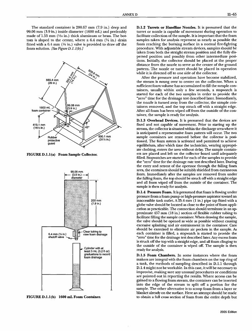
ANNEXD 11-65
The standard container is 200.67 mm (7.9 in.) deep and 99.06 mm (3.9 in.) inside diameter (1600 mL) and preferably made of 1.55 mm (1;16 in.) thick aluminum or brass. The bottom is sloped to the center, where a 6.4 mm (% in.) drain fitted with a 6.4 mm (% in.) valve is provided to draw off the foam solution. [See Figure D. 1. 1 (b).}
n~ 660.4 mm !l? \1-
(26 in.) c>j ~
:( foam container
( 419.1 mm (16% in.)
~ber protective guard
FIGURE D.l.l(a) Foam Sample Collector.
99.06 mm I+- (3.9 in.) -+l I diameter I
6.4 mm (% in.) shutoff valve
1 200mm (7.9 in.)
Cylinder with at least 5 mL (0.2 fl oz) graduations to record foam drainage
FIGURE D.l.l(b) 1600 mLFoam Container.
D.l.2 Turrets or Handline Nozzles. It is presumed that the turret or nozzle is capable of movement during operation to facilitate collection of the sample. It is important that the foam samples taken for analysis represent as nearly as possible the foam reaching the burning surface in a normal fire-fighting procedure. With adjustable stream devices, samples should be taken from both the straight stream position and the fully dispersed position and possibly from other intermediate positions. Initially, the collector should be placed at the proper distance from the nozzle to serve as the center of the ground pattern. The nozzle or turret should be placed in operation while it is directed off to one side of the collector.
Mter the pressure and operation have become stabilized, the stream is swung over to center on the collector. When a sufficient foam volume has accumulated to fill the sample containers, usually within only a few seconds, a stopwatch is started for each of the two samples in order to provide the "zero" time for the drainage test described later. Immediately, the nozzle is turned away from the collector, the sample containers removed, and the top struck off with a straight edge. Mter all foam has been wiped off from the outside of the container, the sample is ready for analysis.
D.l.3 Overhead Devices. It is presumed that the devices are fixed and not capable of movement. Prior to starting up the stream, the collector is situated within the discharge area where it is anticipated a representative foam pattern will occur. The two sample containers are removed before the collector is positioned. The foam system is activated and permitted to achieve equilibrium, after which time the technician, wearing appropriate clothing, enters the area without delay. The sample containers are placed and left on the collector board until adequately filled. Stopwatches are started for each of the samples to provide the "zero" time for the drainage rate test described later. During the entry and retreat of the operator through the falling foam area, the containers should be suitably shielded from extraneous foam. Immediately after the samples are removed from under the falling foam, the top should be struck off with a straight edge and all foam wiped off from the outside of the container. The sample is then ready for analysis.
D.l.4 Pressure Foam. It is presumed that foam is flowing under pressure from a foam pump or high-pressure aspirator toward an inaccessible tank outlet. A 25.4 mm (1 in.) pipe tap fitted with a globe valve should be located as close to the point of foam application as practicable. The connection should terminate in an approximate 457 mm (18 in.) section of flexible rubber tubing to facilitate filling the sample container. When drawing the sample, the valve should be opened as wide as possible without causing excessive splashing and air entrainment in the container. Care should be exercised to eliminate air pockets in the sample. As each container is filled, a stopwatch is started to provide the "zero" time for the drainage test described later. Any excess foam is struck off the top with a straight edge, and all foam clinging to the outside of the container is wiped off. The sample is then ready for analysis.
D.l.5 Foam Chambers. In some instances where the foam makers are integral with the foam chambers on the top ring of a tank, the methods of sampling described in D.1.1 through D.1.4 might not be workable. In this case, it will be necessary to improvise, making sure any unusual procedures or conditions are pointed out in reporting the results. Where access can be gained to a flowing foam stream, the container can be inserted into the edge of the stream to split off a portion for the sample. The other alternative is to scoop foam from a layer or blanket already on the surface. Here an attempt should be made to obtain a full cross section of foam from the entire depth but
2005 Edition

11-66 LOW-, MEDIUM-, AND HIGH-EXPANSION FOAM
without getting any fuel below the foam layer. The greatest difficulty inherent in sampling from a foam blanket is the undesirable lag-in-time factor involved in building up a layer deep enough to scoop a sample. At normal rates of application, it can take a few minutes to build up the several inches in depth required, and this time is likely to affect the test results. The degree of error thus incurred will in tum depend on the type of foam involved, but it can vary from zero percent to several hundred percent. In a Moeller tube installation, it is advisable to sample right alongside the tube as foam oozes out in sufficient volume. Immediately after filling the container, a stopwatch is started to provide the "zero" time for the drainage test described later. Any excess foam is struck off the top with a straightedge, and all foam wiped off from the outside of the container. The sample is then ready for analysis.
D.1.6 Foam Testing. The foam samples, as obtained in the procedures described in D.1.1 through D.1.5, are analyzed for expansion, 25 percent drainage time, and foam solution concentration. It is recommended that duplicate samples be obtained whenever possible and the results averaged for the final value. However, when a shortage of personnel or equipment or both creates a hardship, one sample should be considered acceptable.
The following apparatus is required:
(1) Two 1600 mL (54.1 fl oz) sample containers (2) One foam collector board (3) One balance [triple beam balance, 2610 g (5.7Ib) capacity]
D.1.7 Procedure. Prior to the testing, the empty containers fitted with a drain hose and clamp should be weighed to obtain the tare weight. (All containers should be adjusted to the same tare weight to eliminate confusion in handling.) Each foam sample is weighed to the nearest gram and the expansion calculated from the following equation:
1600 . -----------= ExpanSIOn (full weight - empty weight)
D.1.8 Foam 25 Percent Drainage Tune Determination. The rate at which the foam solution drops out from the foam mass is called the drainage rate and is a specific indication of degree of water retention ability and the fluidity of the foam. A single value is used to express the relative drainage rates of different foams in the "25 percent drainage time," which is the time in minutes that it takes for 25 percent of the total solution contained in the foam in the sample containers to drain.
The following apparatus are required:
(1) Two stopwatches (2) One sample stand (3) 3.38 fl oz (100 mL) capacity plastic graduates
D.1.9 Procedure. This test is performed on the same sample as used in the expansion determination. Dividing the net weight of the foam sample by 4 will give the 25 percent volume (in milliliters) of solution contained in the foam. To determine the time required for this volume to drain out, the sample container should be placed on a stand, as indicated in Figure D.1.1 (b), and the accumulated solution in the bottom of the container should be drawn off into a graduate at regular, suitable intervals. The time intervals at which the accumulated solution is drawn off are dependent on the foam expansion. For foams of expansion 4 to 10, 30-second intervals should be used, and for foams of expansion 10 and higher, 4-minute intervals should be used because of the slower drainage rate of these foams. In this way, a timedrainage-volume relationship is obtained, and after the 25 percent volume has been exceeded, the 25 percent drainage time is
2005 Edition
interpolated from the data. The following example shows how this is done. The net weight of the foam sample is 180 grams. Since 1 gram of foam solution occupies a volume of essentially 20 mL (0.68 fl oz), the total volume of foam solution contained in the given sample is 180 mL (6.1 fl oz).
. 1600 ExpanSIOn = --- = 8.9
180mL
180mL 25% volume = --- = 45 mL
4
The time-solution volume data is recorded as shown in Table D.1.9.
The 25 percent volume of 1.52 fl oz (45 mL) falls between the 2.0- and 2.5-minute period. The proper increments to add to the lower value of 2.0 minutes is determined by interpolation of the data:
45 mL (25% vol.) - 40 mL (2.0 min vol.)
50 mL (2.5 min vol.)-40 mL (2.0 min vol.)
5 1
10 2
The 25 percent drainage time is halfway between 2.0 and 2.5 minutes, or 2.25 minutes, which is rounded off to 2.3 minutes.
An effort should be made to conduct foam tests with water temperatures between 15.6°C and 26.7°C (60°F and 80°F). The water, air, and foam temperatures should be noted in the results. Lower water temperature tends to depress the expansion values and increase the drainage time values. When handling fastdraining foams, remember that they lose their solution rapidly and that the expansion determination should be carried out with speed in order not to miss the 25 percent drainage volume. The stopwatch is started at the time the foam container is fIlled and continues to run during the time the sample is being weighed. It is recommended that expansion weighing be deferred until after the drainage CUIVe data has been received.
Table D.1.9 Foam Sample Drain Tune
Drained Solution Volume
Time (min) mL fl oz
0 0 0 0.5 10 0.34 1.0 20 0.68 1.5 30 1.0 2.0 40 1.4 2.5 50 1.7 3.0 60 2.0
D.2 Foam Solution Concentration Determination.
D.2.1 General. This test is used to determine the percent concentration of a foam concentrate in the water being used to generate foam. It typically is used as a means of determining the accuracy of a system's proportioning equipment. If the level of foam concentrate injection varies widely from that of the design, it can abnormally influence the expansion and drainage foam quality values, which can influence the foam's fire performance. There are two acceptable methods for measuring foam concentrate percentage in water. Both methods are based on comparing foam solution test samples to premeasured solutions that are plotted on a baseline graph of percent concentration versus instrument reading.

ANNEXD 11-67
D.2.1.1 Refractive Index Method. A handheld refractometer is used to measure the refractive index of the foam solution samples. This method is not particularly accurate for AFFF or alcohol-resistantAFFFs since they typically exhibit very low refractive index readings. For this reason, the conductivity method might be preferred where these products are used.
D.2.1.1.1 Equipment. A base (calibration) curve is prepared using the following apparatus:
(1) Four 100 mL (3.4 fl oz) or larger plastic bottles with caps (2) One measuring pipette [10mL(0.34floz)] orsyringe [10cc
(0.34 fl oz)] (3) One 100 mL (3.4 fl oz) or larger graduated cylinder (4) Three plastic-coated magnetic stirring bars (5) One handheld refractometer - American Optical Model
10400 or 10441, Atago NI, or equivalent (6) Standard graph paper (7) Ruler or other straight edge
D.2.1.1.2 Procedure. Using water and foam concentrate from the system to be tested, make up three standard solutions using the 100 mL (3.4 fl oz) or larger graduate. These samples should include the nominal intended percentage ofinjection, the nominal percentage plus 1 percent, and the nominal percentage minus 1 percent. Place the water in the 100 mL (3.4 fl oz) orlarger graduate (leaving adequate space for the foam concentrate), and then carefully measure the foam concentrate samples into the water using the syringe. Use care not to pick up air in the foam concentrate samples. Pour each measured foam solution from the 100 mL (3.4 fl oz) or larger graduate into a 100 mL (3.4 fl oz) plastic bottle. Each bottle should be marked with the percent solution it contains. Add a plastic stirring bar to the bottle, cap it, and shake it thoroughly to mix the foam solution.
Mter the foam solution samples are thoroughly mixed, a refractive index reading should be taken of each percentage foam solution sample. This is done by placing a few drops of the solution on the refractometer prism, closing the cover plate, and observing the scale reading at the dark field intersection. Since the refractometer is temperature compensated, it can take 10 seconds to 20 seconds for the sample to be read properly. It is important to take all refractometer readings at ambient temperatures of 10°C (50°F) or above. Using standard graph paper, plot the refractive index readings on one axis and the percent concentration readings on the other. (See Figure D.2.1.1.2.)
This plotted curve will serve as the known baseline for the test series. Set the solution samples aside in the event the measurements need to be checked.
D.2.1.1.3 Sampling and Analysis. Collect foam solution samples from the proportioning system, using care to be sure the sample is taken at an adequate distance downstream from the proportioner being tested. Take refractive index readings of the sample and compare them to the plotted curve to determine the percentage of the samples.
D.2.1.2 Conductivity Method. This method is based on changes in electrical conductivity as foam concentrate is added to water. A handheld conductivity meter, shown in Figure D.2.1.2, is used to measure the conductivity of foam solutions in microsiemen units. Conductivity is a very accurate method, provided there are substantial changes in conductivity, as foam concentrate is added to the water in relatively low percentages. Since salt or brackish water is very conductive, this method might not be suitable due to small conductivity changes as foam concentrate is added. It will be necessary to make foam and water solutions in advance to determine if adequate changes in conductivity can be detected if the water source is salty or brackish.
1.338
1.337 ~
"C .~
~
~ 'iii II:
1.336
1.335
o
I I I I I L I I I I II I
_10.1 _I 1 1 1 1_ 1.1 1
31 Yj f?~~ ~oIIUfl~nl
: Control Sample - 'Yo. Index -- 2 1.3353 - 3 1.3362 -- 4 1.3371
II'
""" II(
2 3 4 Percent concentration
FIGURE D.2.1.1.2 Typical Graph of Refractive Index Versus Foam Concentration.
FJ[GURE D.2.1.2 Equipment Needed for Conductivity Method of Proportioning Measurement.
D.2.1.2.1 Equipment. Prepare a base (calibration) curve using the following apparatus:
(1) Four 100 mL (3.4 fl oz) or larger plastic bottles with caps (2) One measuring pipette [10mL(0.34floz)] or syringe [lOcc
(0.34 fl oz)] (3) One 100 mL (3.4 fl oz) or larger graduated cylinder (4) Three plastic-coated magnetic stirring bars
2005 Edition

11-68 LOW-, MEDIUM-, AND HIGH-EXPANSION FOAM
(5) A portable temperature compensated conductivity meterOmega Model CDH-70, VWRScientific Model 23198-014, or equivalent
(6) Standard graph paper (7) Ruler or other straight edge
D.2.1.2.2 Procedure. Using the water and foam concentrate from the system to be tested, make up three standard solutions using the 100 mL (3.4 fl oz) or larger graduate. These samples should include the nominal intended percentage of injection, the nominal percentage plus 1 percent, and the nominal percentage minus 1 percent. Place the water in the 100 mL (3.4 fl oz) or larger graduate (leaving adequate space for the foam concentrate), and then carefully measure the foam concentrate samples into the water using the syringe. Use care not to pick up air in the foam concentrate samples. Pour each measured foam solution from the 100 mL (3.4 fl oz) or larger graduate into a 100 mL (3.4 fl oz) or larger plastic bottle. Each bottle should be marked with the percent solution it contains. Add a plastic stirring bar to the bottle, cap it, and shake it thoroughly to mix the foam solution.
Mter making the three foam solutions in this manner, measure the conductivity of each solution. Refer to the instructions that came with the conductivity meter to determine proper procedures for taking readings. It will be necessary to switch the meter to the correct conductivity range setting in order to obtain a proper reading. Most synthetic-based foams used with freshwater result in foam solution conductivity readings of less than 2000 microsiemens. Protein-based foams generally produce conductivity readings in excess of 2000 in freshwater solutions. Due to the temperature compensation feature of the conductivity meter, it can take a short time to obtain a consistent reading.
Once the solution samples have been measured and recorded, set the bottles aside for control sample reference. The conductivity readings then should be plotted on the graph paper. (See Figure D.2.1.2.2.) It is most convenient to place the foam solution percentage on the horizontal axis and the conductivity readings on the vertical axis.
Use a ruler or straight edge to draw a line that approximates connecting all three points. While it might not be possible to hit all three points with a straight line, they should be very close. If not, repeat the conductivity measurements and, if necessary, make new control sample solutions until all three points plot in a nearly straight line. This plot will serve as the known base (calibration) curve to be used for the test series.
D.2.1.2.3 Sampling and Analysis. Collect foam solution samples from the proportioning system, using care to be sure the sample is taken at an adequate distance downstream from the proportioner being tested. Using foam solution samples that are allowed to drain from expanded foam can produce misleading conductivity readings and, therefore, this procedure is not recommended.
Once one or more samples have been collected, read their conductivity and find the corresponding percentage from the base curve prepared from the control sample solutions.
D.3 Interpretation of Foam Test Results. Where the intent of conducting the tests described in D.1 and D.2 is to check the operating efficiency or standby condition, it is necessary only to compare the results with the manufacturers' standards. The manufacturers should be consulted if any appreciable deviations occur.
Mter a short period of experience with the test procedure, it will be observed that foams exist in a wide variety of physical properties. Not only can the expansion vary in value from 3 to 20, but at the same time the 25 percent drainage time can also vary from a few seconds to several hours.
2005 Edition
1100
1000
!II c: Q)
E 900 Q) ·iii e 0 ·E .!: Z. :~ 13 800 ~ "0 c: 0 ()
700
o
I I I I I I I I
I I_I I I I I I I I
3?i f?~"1 ~olluri~nl '= Control Sample - % -- 2 - 3 -- 4
condo 724 886 1041
f
J
f
II n
2 3 Percent concentration
4
FIGURE D.2.1.2.2 Typical Graph of Conductivity Versus Foam Concentration.
These variations result in foams that range in appearance from a watery consistency to the stiffest whipped cream.
It is observed here that the foam solution rapidly drains out of the very watery foams, while the dropout is very slow with the stiff foams. It is not possible to make a foam that is fluid and free flowing and, at the same time, able to hold onto its foam solution. From the standpoint of quickly forming a cohesive foam blanket and rapid flow around obstructions, a fluidtype foam is desirable; however, foams of this nature lose their water more rapidly, which may reduce their resistance to flame burnback and shorten the effective time of sealability. On the other hand, foams that retain their water for a long time are stiff and do not spread readily over a burning area. Thus, good fire-fighting practice indicates a compromise between these two opposite foam properties in order to obtain an optimum foam. An optimum foam is defined as that foam, with physical properties defined by expansion and drainage time, that will extinguish a fire faster, at a lower application rate, or with less water consumed than any other foam.
Numerous test fires conducted in the course of research and development work have shown that the characteristics of an optimum foam depend on the type of the fire and the manner of foam application. Experience over many years of satisfactory results has supported this viewpoint For example, in a large fuel storage tank, foam may be gently applied from one chamber and be required to flow 19.8 m (65 ft) across a burning surface to seal off the fuel. In this case, the optimum foam is physically different from that applied in a splashing manner from a turret that can direct the foam application as needed, where the foam has to flow no more than 1067 mm (42 in.) to form a seal. The forma-

ANNEXE 11-69
tion of a complete specification for the various methods of application has not as yet been accomplished; however, for guidance purposes, the best data available to date are presented.
D.4 fuspection of Foam Concentrate. In order to detennine the condition of the apparatus and foam concentrate and in order to train personnel, foam should be produced annually with portable foam nozzles. Following this operation, the concentrate container (can) should be cut open and examined for deposits of sludge, scale, and so forth, which are capable of impairing the operation of the equipment.
Where the concentrate is stored in tanks, a sample should be drawn from the bottom of the tank annually, and actual foam production tested as specified above, using a portable foam nozzle and the withdrawn sample to verify the quality of foam produced. In the event that sludging of the concentrate is noted, the manufacturer should be promptly consulted.
Dateoffire ________________________________ __ Tlmeoffire-------__________ _
Location [city, state, county, facility (if available)]
Size offire (dimension oftank, pit, spill, and extent involved) ____________________ _
Ignition source (specify if test) ______________ __ Method of detection ______________________ _ Fuel General type (indicate percentage polar
solvent content or additives) ________ _ Reid vapor pressure (psia) ______________ _ Initial temperature __________________ _ Boilingrange _____________ ___ Flash point ______________ _ Depth before fire Fuel _________ _
Water bottom _______ _ Depth after fire Fuel ------___ __
Water bottom ________ _ Ambient conditions Temperature ________ _
Humidity __________ _ Precipitation _______ _ Wind direction _______ _ Wind speed including gusts __
Preburn time prior to foam application _______ _
Control time (90%) ______________ _ Extinguishing time __________________ _ Discharging time after extinguishment _________ _
Tlmeofreflash _______________________ _
Foam concentrate [Foam type (estimate amount of each type)]
Protein (P) _____________________ _ Fluoroprotein (FP) _____________ _ Aqueous film-forming (AFFF) ________ _ Film-forming fluoroproteins (FFP) __________ _ Synthetic (SYN) ____________ _ Alcohol-resistant (ARF) ___________ _ (Indicate ifP, FP, or AFFF base)I-_______ _ Other(name) _______________ ___
FIGURE E.I Foam Fire-Fighting Data Sheet.
Annex E Foam Fire-Fighting Data Sheet
This annex is not a part of the requirements of this NFPA document but is included for infonnational purposes only.
E.I The following data sheet (see Figure E.1) is used to record and evaluate data on actual fires and fire tests where fire-fighting foam is used. This data might be considered in evaluating suggestions for changes to this standard. Persons having knowledge of such fires are requested to complete the fonn and send it to the following:
National Fire Protection Association 1 Batterymarch Park Quincy, MA02169-7471
In the case of multiple attacks or reflashes of the same fire, additional data sheets should be prepared for each attack.
Discharge devices Type (handline, monitor, foam maker, subsurface injection, etc.) _______________________ _ Method of application (plunging, gentle, backboard) _______________ _ Number __________________________ _ Flow through each _______________________ _ Estimated pressure at each " ___________________ _
Application rate, total (gpm/ft2) ___________ _ Proportioning
Percent (1%, 3%, 6%, other - identify if premix) __ _ Type of pro portioner (pickup tube, in-line inductor, pressure proportioning tank, pump proportioner, metered proportioning, bladder tank and controller, coupled water motor pump)
Water Salt __ Fresh __ Other (Explain) ______ _ Temperature _______________________ _ Source __________________________ ___ Additives ________________________ ___
Description of hazard/facility (indoors, outdoors, confined or unconfined, material of tank) ________ _
Exterior cooling rate ___________________ _ Foam properties (identify apparatus used)
Apparatus _________________________ __ Expansion ___________________________ _ 25%drainage ________________ ___ Burnback ___________________________ _ Sealability ________________ _
Brief scenario _____________________ _
Unusual circumstances _________________ _ Test laboratory or other third-party observer ______ _
Submitter ____________________________ _ Point of contact _______________________ _ Telephone number ___________________ _
2005 Edition

11-70 LOW-, MEDIUM-, AND HIGH-EXPANSION FOAM
Annex F Foam Environmental Issues
This annex is not a part of the requirements of this NFPA document but is included for informational purposes only.
F.1 Overview. Fire-fighting foams as addressed in this standard serve a vital role in fire protection throughout the world. Their use has proven to be essential for the control of flammable liquid fire threats inherent in airport operations, fuel farms and petroleum processing, highway and rail transportation, marine applications, and industrial facilities. The ability of foam to rapidly extinguish flammable liquid spill fires has undoubtedly saved lives, reduced property loss, and helped minimize the global pollution that can result from the uncontrolled burning of flammable fuels, solvents, and industrial liquids.
However, with the ever-increasing environmental awareness, recent concern has focused on the potential adverse environmental impact of foam solution discharges. The primary concerns are fish toxicity, biodegradability, treatability in wastewater treatment plants, and nutrient loading. All of these are of concern when the end-use foam solutions reach natural or domestic water systems. Additionally, the U.S. Environmental Protection Agency (EPA) has highlighted a potential problem with some foam concentrates by placing glycol ethers and ethylene glycol, common solvent constituents in some foam concentrates, on the list of hazardous air pollutants under the 1990 Clean Air Act Amendments.
The purpose of this annex is to address the following:
(1) Provide foam users with summary information on foam environmental issues
(2) Highlight applicable regulatory status (3) Offer guidelines for coping with regulations, and provide
suggested sources for additional information (4) Encourage planning for foam discharge scenarios (in
cluding prior contact with local wastewater treatment plant operators)
It should be emphasized that it is not the intent of this annex to limit or restrict the use of fire-fighting foams. The foam committee believes that the fire safety advantages of using foam are greater than the risks of potential environmental problems. The ultimate goal of this section is to foster use of foam in an environmentally responsible manner so as to minimize risk from its use.
F.2 Scope. The information provided in this section covers foams for Class B combustible and flammable liquid fuel fires. Foams for this purpose include protein foam, fluoroprotein foam, film-forming fluoroprotein foam (FFFP) , and synthetic foams such as aqueous film-forming foam (AFFF).
Some foams contain solvent constituents that can require reporting under federal, state, or local environmental regulations. In general, synthetic foams, such as AFFF, biodegrade more slowly than protein-based foams. Protein-based foams can be more prone to nutrient loading and treatment facility "shock loading" due to their high ammonia nitrogen content and rapid biodegradation, respectively.
This section is primarily concerned with the discharge of foam solutions to wastewater treatment facilities and to the environment The discharge of foam concentrates, while a related subject, is a much less common occurrence. All manufacturers of foam concentrate deal with clean-up and disposal of spilled concentrate in their MSDS sheets and product literature.
F.3 Discharge Scenarios. A discharge of foam water solution is most likely to be the result of one of four scenarios:
2005 Edition
(1) Manual fire-fighting or fuel-blanketing operations (2) Training (3) Foam equipment system tests (4) Fixed system releases
These four scenarios include events occurring at such places as aircraft facilities, fire fighter training facilities, and special hazards facilities (such as flammable/hazardous warehouses, bulk flammable liquid storage facilities, and hazardous waste storage facilities). Each scenario is considered separately in F.3.1 through F.3.4.
F.3.1 Fire-Fighting Operations. Fires occur in many types of locations and under many different circumstances. In some cases, it is possible to collect the foam solution used; and in others, such as in marine fire fighting, it is not. These types of incidents include aircraft rescue and fire-fighting operations, vehicular fires (i.e., cars, boats, train cars), structural fires with hazardous materials, and flammable liquid fires. Foam water solution that has been used in fire-fighting operations will probably be heavily contaminated with the fuel or fuels involved in the fire. It is also likely to have been diluted with water discharged for cooling purposes.
In some cases, the foam solution used during fire department operations can be collected. However, it is not always possible to control or contain the foam. This can be a consequence of the location of the incident or the circumstances surrounding it
Event-initiated manual containment measures are the operations usually executed by the responding fire department to contain the flow of foam water solution when conditions and manpower permit Those operations include the following measures:
(1) Blocking sewer drains: this is a common practice used to prevent contaminated foam water solution from entering the sewer system unchecked. It is then diverted to an area suitable for containment.
(2) Portable dikes: these are generally used for land-based operations. They can be set up by the fire department personnel during or after extinguishment to collect run-off.
(3) Portable booms: these are used for marine-based operations, which are set up to contain foam in a defined area. These generally involve the use of floating booms within a natural body of water.
F.3.2 Training. Training is normally conducted under circumstances conducive to the collection of spent foam. Some fire training facilities have had elaborate systems designed and constructed to collect foam solution, separate it from the fuel, treat it, and - in some cases - re-use the treated water. At a minimum, most fire training facilities collect the foam solution for discharge to a wastewater treatment facility. Training can include the use of special training foams or actual firefighting foams. Training facility design should include a containment system. The wastewater treatment facility should first be notified and should give permission for the agent to be released at a prescribed rate.
E3.3 System Tests. Testing primarily involves engineered, fixed foam fire-extinguishing systems. Two types of tests are conducted on foam systems: acceptance tests, conducted pursuant to installation of the system; and maintenance tests, usually conducted annually to ensure the operability of the system. These tests can be arranged to pose no hazard to the environment. It is possible to test some systems using water or other nonfoaming, environmentally acceptable liquids in the place of foam concentrates if the AHJ permits such substitutions.

ANNEXF 11-71
In the execution of both acceptance and maintenance tests, only a small amount of foam concentrate should be discharged to verify the correct concentration of foam in the foam water solution. Designated foam water test ports can be designed into the piping system so that the discharge of foam water solution can be directed to a controlled location. The controlled location can consist of a portable tank that would be transported to an approved disposal site by a licensed contractor. The remainder of the acceptance test and maintenance test should be conducted using only water.
E3.4 Fixed System Releases. This type of release is generally uncontrolled, whether the result of a fire incident or a malfunction in the system. The foam solution discharge in this type of scenario can be dealt with by event-initiated operations or by engineered containment systems. Event-initiated operations encompass the same temporary measures that would be taken during fire department operations: portable dikes, floating booms, and so forth. Engineered containment would be based mainly on the location and type of facility, and would consist of holding tanks or areas where the contaminated foam water solution would be collected, treated, and sent to a wastewater treatment facility at a prescribed rate.
E4 FIxed Systems. Facilities can be divided into those without an engineered containment system and those with an engineered containment system.
E4.1 Facilities without Engineered Containment. Given the absence of any past requirements to provide containment, many existing facilities simply allow the foam water solution to flow out of the building and evaporate into the atmosphere or percolate into the ground. The choices for containment of foam water solution at such facilities fall into two categories: event-initiated manual containment measures and installation of engineered containment systems.
Selection of the appropriate choice is dependent on the location of the facility, the risk to the environment, the risk of an automatic system discharge, the frequency of automatic system discharges, and any applicable rules or regulations.
"Event-initiated manual containment measures" will be the most likely course of action for existing facilities without engineered containment systems. This can fall under the responsibility of the responding fire department and include such measures as blocking storm sewers, constructing temporary dikes, and deploying floating booms. The degree of such measures will primarily be dictated by location as well as available resources and manpower.
The "installation of engineered containment systems" is a possible choice for existing facilities. Retrofitting an engineered containment system is costly and can adversely affect facility operations. There are special cases, however, that can warrant the design and installation of such systems. Such action is a consideration where an existing facility is immediately adjacent to a natural body of water and has a high frequency of activation.
E4.2 Facilities with Engineered Containment. Any engineered containment system will usually incorporate an oil/water separator. During normal drainage conditions (i.e., no foam solution runoff), the separator functions to remove any fuel particles from drainage water. However, when foam water solution is flowing, the oil/water separator must be bypassed so that the solution is diverted directly to storage tanks. This can be accomplished automatically by the installation of motorized valves set to open the bypass line upon activation of the fixed fire-extinguishing systems at the protected property.
The size of the containment system is dependent on the duration of the foam water flow, the flow rate, and the maximum anticipated rainfall in a 24-hour period. Most new containment systems will probably only accommodate individual buildings. However, some containment systems can be designed to accommodate multiple buildings, depending upon the topography of the land and early identification in the overall site planning process.
The specific type of containment system selected will also depend upon location, desired capacity, and function of facilities in question. The systems include earthen retention systems, belowground tanks, open-top inground tanks, and sump and pump designs (i.e., lift stations) piped to aboveground or inground tanks.
The earthen retention designs consist of open-top earthen berms, which usually rely upon gravity-fed drainage piping from the protected building. They can simply allow the foam water solution to percolate into the ground or can include an impermeable liner. Those containing an impermeable liner can be connected to a wastewater treatment facility or can be suction pumped out by a licensed contractor.
Closed-top, belowground storage tanks can be the least environmentally acceptable design approach. They usually consist of a gravity-fed piping arrangement and can be suction pumped out or piped to a wastewater treatment facility. A potential and frequent problem associated with this design is the leakage of groundwater or unknown liquids into the storage tank.
Open-top, belowground storage tanks are usually lined concrete tanks that can rely on gravity-fed drainage piping or a sump and pump arrangement. These can accommodate individual or multiple buildings. They must also accommodate the maximum anticipated rainfall in a 24-hour period. These are usually piped to a wastewater treatment facility.
Aboveground tanks incorporate a sump and pump arrangement to closed, aboveground tanks. Such designs usually incorporate the use of one or more submersible or vertical shaft, large-capacity pumps. These can accommodate individual or multiple buildings.
E4.3 New Facilities. The decision to design and install a fixed foam water solution containment system is dependent on the location of the facility, the risk to the environment, possible impairment of facility operations, the design of the fixed foam system (Le., automatically or manually activated), the ability of the responding fire department to execute event-initiated containment measures, and any pertinent regulations.
New facilities might not warrant the expense and problems associated with containment systems. Where the location of a facility does not endanger groundwater or any natural bodies of water, this can be an acceptable choice, provided the fire department has planned emergency manual containment measures.
Where conditions warrant the installation of engineered containment systems, there are a number of considerations. They include size of containment, design and type of containment system, and the capability of the containment system to handle individual or multiple buildings. Engineered containment systems can be a recommended protective measure where foam extinguishing systems are installed in facilities that are immediately adjacent to a natural body of water. These systems can also be prudent at new facilities, where site conditions permit, to avoid impairment of facility operations.
2005 Edition

11-72 LOW-, MEDIUM-, AND HIGH-EXPANSION FOAM
E5 Disposal Alternatives. The uncontrolled release of foam solutions to the environment should be avoided. Alternative disposal options are as follows:
(1) Discharge to a wastewater treatment plant with or without pretreatment
(2) Discharge to the environment after pretreatment (3) Solar evaporation (4) Transportation to a wastewater treatment plant or hazard
ous waste facility
Foam users, as part of their planning process, should make provisions to take the actions necessary to utilize whichever of these alternatives is appropriate for their situation. Section F.6 describes the actions that can be taken, depending on the disposal alternative that is chosen.
E6 Collection and Pretreatment of Foam Solutions Prior to Disposal.
F.6.1 Collection and Containment. The essential first step in employing any of these alternatives is collection of the foam solution. As noted above, facilities that are protected by foam systems normally have systems to collect and hold fuel spills. These systems can also be used to collect and hold foam solution. Training facilities are, in general, designed so that foam solution can be collected and held. Fire fighters responding to fires that are at other locations should attempt, insofar as is practical, to collect foam solution run-offwith temporary dikes or other means.
F.6.2 Fuel Separation. Foam solution that has been discharged on a fire and subsequently collected will usually be heavily contaminated with fuel. Since most fuels present their own environmental hazards and will interfere with foam solution pretreatment, an attempt should be made to separate as much fuel as possible from the foam solution. As noted in FA.2, the tendency of foam solutions to form emulsions with hydrocarbon fuels will interfere with the operation of conventional fuel-water separators. An alternative is to hold the collected foam solution in a pond or lagoon un til the emulsion breaks and the fuel can be separated by skimming. This can take from several hours to several days. During this time, agitation should be avoided to prevent the emulsion from reforming.
E6.3 Pretreatment Prior to Discharge.
F.6.3.1 Dilution. Foam manufacturers and foam users recommend dilution of foam solution before it enters a wastewater treatment plant. There is a range of opinion on the optimum degree of dilution. It is generally considered that the concentration of foam solution in the plant influent should not exceed 1700 ppm (588 gal of plant influent per gallon of foam solution). This degree of dilution is normally sufficient to prevent shock loading and foaming in the plant. However, each wastewater treatment plant must be considered as a special case, and those planning a discharge of foam solution to a wastewater treatment facility should discuss this subject with the operator of the facility in advance.
Diluting waste foam solution 588:1 with water is an impractical task for most facilities, especially when large quantities of foam solution are involved. The recommended procedure is to dilute the foam solution to the maximum amount practical and then meter the diluted solution into the sewer at a rate which, based on the total volume of plant influent, will produce a foam solution concentration of 1700 ppm or less.
2005 Edition
For example, if the discharge is to be made to a 6 million gal/day treatment plant, foam solution could be discharged at the rate of7 gpm (6,000,000 gal/day divided by 1440 minutes/ day divided by 588 equals 7 gpm). The difficulties of metering such a low rate of discharge can be overcome by first diluting the foam solution by 10:1 or 20:1, permitting discharge rates of 70 gpm or 140 gpm respectively. Dilution should also be considered if the foam solution is to be discharged to the environment in order to minimize its impact.
F.6.3.2 Defoamers. The use of defoamers will decrease, but not eliminate, foaming of the foam solution during pumping, dilution, and treatment. The foam manufacturer should be consulted for recommendations as to the choice of effective defoamers for use with a particular foam concentrate.
E6.3.3 Method for Determining the Effective Amount of Antifoam Apparatus. The effective amount of antifoam is determined by using the following apparatus:
(1) Balance - 1600 g capacity minimum - readability 0.2 g maximum
(2) One 2 L beaker or similar container (3) One 1 gal plastic or glass jug with cap (4) Eyedropper (5) Optional-10 mL pipette
E6.3.3.1 Procedure. Proceed with the following instructions to determine the effective amount of antifoam:
(1) In the 2 L beaker, weigh out 1 g (1 mL) of anti foam using an eyedropper or the pipette.
(2) Add 999 g of water. (3) Mix well. (4) Weigh out 1000 g of the solution to be defoamed and
place it in the gallon jug. (5) Add 10 g (10 mL) of the diluted antifoam to the gallonjug
using the eyedropper or pipette, cap it, and shake vigorously. (6) If the solution in the jug foams, go back to step 5 and
repeat this step until little or no foam is generated by shaking the jug; keep a record of the number of grams (mL) that are required to eliminate the foaming.
(7) The number of grams (mL) of diluted antifoam required to eliminate foaming is equal to the number of parts per million (ppm) of the antifoam as supplied that must be added to the solution to be defoamed.
(8) Calculate the amount of neat antifoam to be added as follows:
W=8.32 VxD+1,000,000
where: V = Volume of solution to be defoamed in U.S. gal D = ppm of antifoam required W = lb of antifoam required
Example 10,000 gal offoam solution require defoaming. The procedure above has determined that 150 ppm of antifoam are needed to defoam this solution: 8.32 x 10,000 x 15071,000,000 = 12A81b.
(9) The amount of antifoam to be added will normally be quite small compared to volume of the solution to be defoamed. The antifoam must be uniformly mixed with the solution to be defoamed. It will aid in the achievement of this objective if the antifoam is diluted as much as is practical with water or the solution to be defoamed prior to addition to the solution containment area. The solution in the containment area must then be agitated to disperse

ANNEXF 11-73
the antifoam uniformly. One method of doing this is to use a fire pump to draft out of the containment area and discharge back into it using a water nozzle set on straight stream. Alternatively, if suitable metering equipment is available, antifoam as supplied or diluted antifoam can be metered into the solution discharge line at the proper concentration.
E7 Discharge of Foam Solution to Wastewater Treatment Facilities. Biological treatment of foam solution in a wastewater treatment facility is an acceptable method of disposal. However, foam solutions have the potential to cause plant upsets and other problems if not carefully handled. The reasons for this are explained in F.7.1 through F.7.4.
E7.1 Fuel Contamination. Foam solutions have a tendency to emulsify hydrocarbon fuels and some polar fuels that are only slightly soluble in water. Water-soluble polar fuels will mix with foam solutions. The formation of emulsions will upset the operation of fuel/water separators and potentially cause the carryover of fuel into the waste stream. Many fuels are toxic to the bacteria in wastewater treatment plants.
E7.2 Foaming. The active ingredients in foam solutions will cause copious foaming in aeration ponds, even at very low concentrations. Aside from the nuisance value of this foaming, the foaming process tends to suspend activated sludge solids in the foam. These solids can be carried over to the outfall of the plant. Loss of activated sludge solids can also reduce the effectiveness of the wastewater treatment. This could cause water quality problems such as nutrient loading in the waterway to which the outfall is discharged. Because some surfactants in foam solutions are highly resistant to biodegradation, nuisance foaming can occur in the outfall waterway.
E7.3 BOD (Biological Oxygen Demand). Foam solutions have high BODs compared to the normal influent of a wastewater treatment plant. If large quantities of foam solution are discharged to a wastewater treatment plant, shock loading can occur, causing a plant upset.
Before discharging foam solutions to a wastewater treatment plant, the plant operator should be contacted. This should be done as part of the emergency planning process. The plant operator will require, at a minimum, a Material Safety Data Sheet (MSDS) on the foam concentrate, an estimate of the five-day BOD content of the foam solution, an estimate of the total volume of foam solution to be discharged, the time period over which it will be discharged, and, if the foam concentrate is protein-based, an estimate of the ammonia nitrogen content of the foam solution.
The foam manufacturer will be able to provide BOD and ammonia nitrogen data for the foam concentrate, from which the values for foam solution can be calculated. The other required information is site-specific and should be developed by the operator of the facility from which the discharge will occur.
E7.4 Treatment Facilities. Foam concentrates or solutions can have an adverse effect on microbiologically based oily water treatment facilities. The end user should take due account of this before discharging foam systems during testing or training.
E8 Foam Product Use Reporting. Federal (U.S.), state, and local environmental jurisdictions have certain chemical reporting requirements that apply to chemical constituents within foam concentrates. In addition, there are also requirements that apply to the flammable liquids to which the foams are being applied.
For example, according to the U.S. Environmental Protection Agency (EPA), the guidelines in F.8.1 through F.8.4 must be adhered to.
ES.I Releases of ethylene glycol in excess of 5000 Ib are reportable under Sections 102(b) and 103(a) of U.S. EPAComprehensive Environmental Response Compensation & Liability Act (CERCIA). Ethylene glycol is generally used as a freeze-point suppressant in foam concentrates.
ES.2 As of June 12, 1995, the EPA issued a final rule 60 CFR 30926 on several broad categories of chemicals, including the glycol ethers. The EPA has no reportable quantity for any of the glycol ethers. Thus foams containing glycol ethers (butyl carbitol) are not subject to EPA reporting. Consult the foam manufacturer's MSDS to determine if glycol ethers are contained in a particular foam concentrate.
E8.3 The EPA does state that CERCLAliability continues to apply to releases of all compounds within the glycol ether category, even if reporting is not required. Parties responsible for releases of glycol ethers are liable for the costs associated with cleanup and any natural resource damages resulting from the release.
E8.4 The end user should contact the relevant local regulating authority regarding specific current regulations.
E9 Environmental Properties of Hydrocarbon Surfactants and Fluorochemical Surfactants. Fire-fighting foam agents contain surfactants. Surfactants or surface active agents are compounds that reduce the surface tension of water. They have both a strongly "water-loving" portion and a strongly "wateravoiding" portion.
Dish soaps, laundry detergents, and personal health care products such as shampoos are common household products that contain hydrocarbon surfactants.
Fluorochemical surfactants are similar in composition to hydrocarbon surfactants; however, a portion of the hydrogen atoms have been replaced by fluorine atoms. Unlike chlorofluorocarbons (CFCs) and some other volatile fluorocarbons, fluorochemical surfactants are not ozone depleting and are not restricted by the Montreal Protocol or related regulations. Fluorochemical surfactants also have no effect on global warming or climate change. AFFF, fluoroprotein foam, and FFFP are foam liquid concentrates that contain fluorochemical surfactants.
There are environmental concerns with use of surfactants that should be kept in mind when these products are used for extinguishing fires or for fire training. These concerns are as follows:
(1) All surfactan ts have a certain level of toxicity. (2) Surfactants used in fire-fighting foams cause foaming. (3) Surfactants used in fire-fighting foams can be persistent.
(This is especially true of the fluorine-containing portion offluorochemical surfactants.)
(4) Surfactants can be mobile in the environment. They can move with water in aquatic ecosystems and leach through soil in terrestrial ecosystems.
F.9.1 through F.9.5 explain what each of these properties mean and what the properties mean in terms of how these compounds should be handled.
E9.1 ToxicityofSurfactants. Fire-fighting agents, used responsibly and following Material Safety Data Sheet instructions, pose little toxicity risk to people. However, some toxicity does exist
2005 Edition
11-74 LOW-, MEDIUM-, AND HIGH-EXPANSION FOAM
The toxicity of the surfactants in fire-fighting foams, including the fluorochemical surfactants, is a reason to prevent unnecessary exposure to people and to the environment. It is a reason to contain and treat all fire-fighting foam wastes whenever feasible. One should always make plans to contain wastes from training exercises and to treat them following the suppliers' disposal recommendations as well as the requirements of local authorities.
Water that foams when shaken due to contamination from fire-fighting foam should not be ingested. Even when foaming is not present, it is prudent to evaluate the likelihood of drinking water supply contamination and to use alternate water sources until one is certain that surfactant concentrations of concern no longer exist. Suppliers of firefighting foams should be able to assist in evaluating the hazard and in recommending laboratories that can do appropriate analysis when necessary.
E9.2 Surfactants and Foaming. Many surfactants can cause foaming at very low concentrations. This can cause aesthetic problems in rivers and streams, and both aesthetic and operational problems in sewers and wastewater treatment systems. When too much fire-fighting foam is discharged at one time to a wastewater treatment system, serious foaming can occur. The bubbles of foam that form in the treatment system can trap and bring flocks of the activated sludge that treat the water in the treatment system to the surface. If the foam blows off the surface of the treatment system, it leaves a black or brown sludge residue where the foam lands and breaks down.
If too much of the activated sludge is physically removed from the treatment system in foam, the operation of the treatment system can be impaired. Other waste passing through the system will then be incompletely treated until the activated sludge concentration again accumulates. For this reason, the rate of firefighting foam solution discharged to a treatmen t system has to be controlled. Somewhat higher discharge rates can be possible when antifoaming or defoaming agents are used. Foam concentrate suppliers can be contacted for guidance on discharge rates and effective antifoaming or defoaming agents.
E9.3 Persistence of Surfactants. Surfactants can biodegrade slowly and/ or only partially biodegrade. The fluorochemical surfactants are known to be very resistant to chemical and biochemical degradation. This means that, while the non-fluorochemical portion of these surfactants can break down, the fluorinecontaining portion can likely remain. This means that after firefighting foam wastes are fully treated, the waste residual could still form some foam when shaken. It could also still have some toxicity to aquatic organisms if not sufficiendy diluted.
E9.4 Mobility of Surfactants. Tests and experience have shown that some surfactants or their residues can leach through at least some soil types. The resistance of some surfactants to biodegradation makes the mobility of such sUlfactants a potential concern. While a readily degradable compound is likely to degrade as it leaches through soil, this won't happen to all surfactants. Thus, if allowed to soak into the ground, surfactants that don't become bound to soil components can eventually reach groundwater or flow out of the ground into surface water. If adequate dilution has not occurred, surfactants can cause foaming or concerns about toxicity. Therefore, it is inappropriate to allow training waste to continually seep into soil, especially in areas where water resources could be contaminated.
2005 Edition
E9.5 Fluorochemical Surfactants and living Systems. Some fluorochemical surfactants or their persistent degradation products have been found in living organisms.
Annex G Test Method for Marine Fire-Fighting Foam Concentrates Protecting Hydrocarbon Hazards
This annex is not a part of the requirements of this NFPA document but is included for informational purposes only.
G.l Introduction. The following test method has been specifically developed for use in demanding marine applications. It is derived from Federal Specification O-F-555C, which is no longer in print. It specifically incorporates a large surface area of 9.29 m2 (100 ft2), sealability testing, and a burnback test conducted 15 minutes after fire extinction. The test method given here incorporates a high freeboard that is subject to high temperatures; both conditions add to the difficulty of this test method. This test method uses gasoline, a highly challenging test fuel, and requires that fresh fuel be used for each test. This test utilizes a square pan. The geometry of the pan's corners better simulates the complex steel shapes found in ships' cargo holds and bilges than round fire test pans used in other test methods. The test method employs a fixed nozzle, thus removing any bias caused by an operator applying foam at the test facility.
G.2 Test Facility. The test should be conducted at a test facility acceptable to the authority havingjurisdiction.
G.3 Test Apparatus.
G.3.l Pan. The test pan should be of10-gauge steel minimum construction measuring 3 m (10 ft) long x 3 m (10 ft) wide x 0.9 m (3 ft) deep. The sides of the pan should be properly reinforced to prevent warpage due to heat generated during the test.
G.3.2 Nozzle. The test nozzle should be as shown in Figure G.3.2. Alternate nozzles should be approved by the AH]. The nozzle should flow 22.7 L/min (6.0 gpm) at 688.5 kPa (100 psi) inlet pressure.
G.3.3 Fuel. A minimum of 284 L (75 gal) of gasoline is needed to be floated on a sufficient quantity of potable water so that the fuel surface is 0.6 m (2 ft) below the top edge of the tank. For each succeeding test the pan should be completely emptied of the fuel and foam residue from the previous test The gasoline should be commercial unleaded regular motor fuel with an octane rating between 82 and 93 per Federal Specification W-G-1690. The fuel temperature should be not less than 21°C (70°F). An alternate test fuel can be used provided that it has properties equivalent to the unleaded fuel specified above and has been approved by the AI-ij.
G.3.4 Synthetic Sea Water. The composition should be as described in ASTM D 1141.
G.3.5 Conversion Factors.
1 L/min·m2 = 0.0245 gpm/fr 6 L/min·m2 = 0.147 gpm/ft2
3 L/min·m2 = 0.0735 gpm/fr 1 gpm/ft2 = 40.7 L/min·m2
0.24 gpm/ft2 = 9.77 L/min.m2
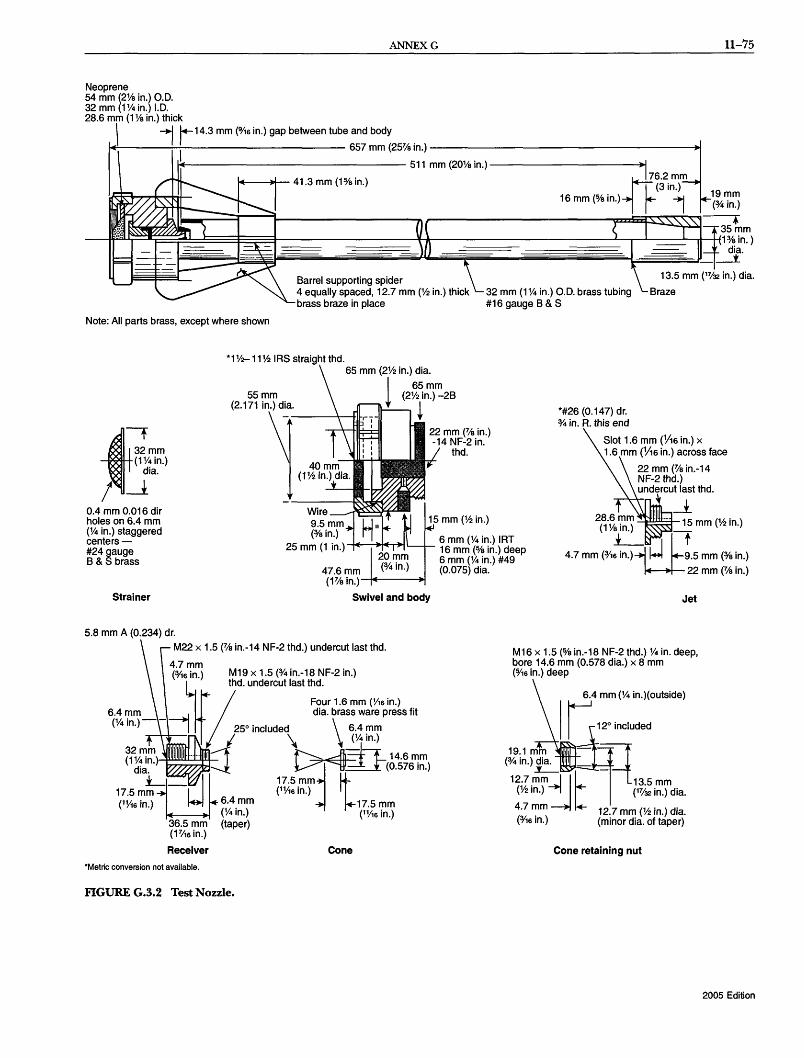
ANNEXG
Neoprene 54 mm (2% in.) 0.0. 32 mm (1 % in.) 1.0. 28.6 mm (1 % in.) thick \ -1 r-14.3 mm (0/16 in.) gap between tube and body
-------------- 511 mm (20% in.)-----------+l_1
11-75
I
II( rf==1 657mm(25~in.)
'II( .' 41.3 mm (1%in.) ~7732i:;)m 16 mm (o/e in.) i 19 mm
(%in.)
1~~~--4-----------~r_--------------_p~~~~--.
~~~e~n~)
1~~~~~~~~~~~~~~~~~~lU~~~~~~~~~~~~~~~~~~~~ dia. I'" _-I.
Barrel supporting spider 4 equally spaced, 12.7 mm (112 in.) thick brass braze in place
32 mm (1 % in.) 0.0. brass tubing #16 gauge B & S
13.5 mm (17'32 in.) dia.
Note: All parts brass, except where shown
*1112-11112 IRS straight thd. 65 mm (2112 in.) dia.
*#26 (0.147) dr. % in. R. this end
Slot 1.6 mm (V16 in.) x 32mm (1%in.)
dia. ft
1.6 mm (V16 in.) across face
I~ Wire 9.5mm
0.4 mm 0.016 dir holes on 6.4 mm (% in.) staggered centers - (0/8 in.) 6 mm (% in.) IRT
25 mm (1 in.)--+IIE-..... ~""L........l.- 16 mm (0/8 in.) deep #24 gauge B & S brass
47.6mm (1% in.)-+Of----~
Strainer Swivel and body
5.8 mm A (0.234) dr.
M22 x 1.5 (% in.-14 NF-2 thd.) undercut last thd.
36.5 mm (FA6 in.)
Receiver
"Metric conversion not available.
M19 x 1.5 (% in.-18 NF-2 in.) thd. undercut last thd.
Four 1.6 mm (V,6 in.) dia. brass ware press fit
250 included \ 6.4 mm \ ~4in.)
~~~14.6mm
~ ~(0.576 in.)
17.5mm t (1V,6 in.)
17.5 mm (1V,6 in.)
Cone
FIGURE G.3.2 Test Nozzle.
6 mm (% in.) #49 (0.075) dia.
Jet
M 16 x 1.5 (0/8 in.-18 NF-2 thd.) % in. deep, bore 14.6 mm (0.578 dia.) x 8 mm (0/16 in.) deep
6.4 mm (% in.)(outside)
I ~~120 included
19.1 mm -:q (% in.) dia.
.:L- --12/.mm 13.5 mm
(V21n.) -+I I k- (17/32 in.) dia.
4.7 ~m ~ l 12.7 mm (% in.) dia. (0/16 In.) (minor dia. of taper)
Cone retaining nut
2005 Edition
11-76 LOW-, MEDIUM-, AND HIGH-EXPANSION FOAM
G.4 Test Procedure.
G.4.1 Fire Extinguishment. Foam concentrate should be sulr jected to four consecutive fire tests by discharging through a 22.7 L/min (6 gpm) nozzle at an inlet gauge pressure maintained at 688.5 kPa (100 psi) ± 13.8 kPa (2 psi), and a water temperature of20 ± 5°C (68 ± 8°F). The concentrate should be at approximately the same temperature as the water. Two of the tests should be conducted with freshwater, and two of the tests should be conducted with salt water as described in Section G.3A. The foam liquid solution should be premixed and applied at a rate of3.0 percent by volume for 3 percent foams, 6.0 percent for 6 percent foams, and so forth. The nozzle should be positioned in the middle of one side of the test pan with the nozzle tip 406.4mm (16in.) directly above the top edge of the test pan. The fire should be permitted to bum freely for 60 seconds before foam application. The foam should be directed across the fire to strike the approximate center of the back side of the pan, 304.8 mm (12 in.) above the fuel level and should be applied for a ::rminute period. (If prior to the test, foam is discharged into the pan to align the nozzle for proper foam stream impact position on the back side of the pan, such foam should be removed from the pan prior to the test.) The following procedures should take place:
(1) Observations. Observations and records are as follows:
(a) Record the period required, after start of foam application, for the foam to spread over the fuel surface as "coverage" time.
(b) Record the period for the fire to be extinguished except for licks of flame at the edges of the foam blanket as "control" time.
(c) Record the period for complete extinguishment as "extinguishment" time.
(2) Record. Record the name of the manufacturer, foam type, trade name, batch number, and date of manufacture.
G.4.2 Sealability. A lighted torch should be passed continuously over the foam blanket starting 10 minutes after the end of foam discharge. Fourteen minutes after completion of foam application, the lighted torch should be applied over the foam blanket for 1 minute with the torch touching the foam blanket but not penetrating the foam blanket by more than 12.7 mm (1;2 in.). The torch should touch the blanket at least every 0.6 m (2 ft) along the sides of the test pan, at points where the foam blanket appears significantly less than the average thickness, in all four corners of the pan, and at random points in the main area ofthe pan. However, the torch should not be dragged through the foam.
G.4.3 Burnback. One of the methods described in GA.3.1 and GA.3.2 should be used.
G.4.3.1 Method 1. Fifteen minutes after completion of the foam application, an opening 3870 mm2 (6 in.2
) should be made in the foam blanket approximately 0.6 m (2 ft) from the side of the pan. The exposed fuel should be reignited with a torch and permitted to bum for 5 minutes. Mter the ::rminute burning period, the area involved in flames should be determined.
G.4.3.2 Method 2. As an alternative to Method 1, two 0.3 m (1 ft) diameter stove pipes should be placed in the foam blanket during the sealability test, at least 0.6 m (2 ft) from the sides of the pan, and the foam inside the stove pipes should be removed. At 15 minutes after the end of the foam discharge, the exposed fuel inside the stove pipes should be ignited by torch and permitted to burn for 1 minute. The first stove pipe
2005 Edition
should then be removed. Mer an additional 4-minute burning period, the area involved in flames should be determined. If, upon removal of the pipe, foam covers the exposed fuel area and extinguishes the fire, the fuel inside the second stove pipe should be ignited and allowed to burn freely for 1 minute. The second stove pipe should then be removed, and the area involved at 20 minutes after the end of foam discharge should be determined. If, upon removal of the second pipe, the foam again covers the exposed fuel and extinguishes the fire, no further bumback tests are necessary.
G.5 Acceptance Criteria.
G.5.1 Fire Performance. The foam as received should have a coverage time of not more than 2 minutes, a control time of not more than 5 minutes, and complete fire extinguishment in not more than 5 minutes after start of foam application.
G.5.2 Sealability. The foam blanket should protect the fuel below the foam from reignition by a lighted torch for a period of not less than 15 minutes after the end of foam application. Any ignition of fuel vapors above the foam blanket should result in complete self-extinguishment prior to the end of the test period. Record in detail the type, location, and duration of any burning observed.
G.5.3 Burnback.
G.5.3.1 Method 1. The foam blanket should prevent the spread offire beyond an area approximately 12,902 mm2 (20 in.2
).
G.5.3.2 Method 2. The area involved in flames should not exceed 0.25 m2 (2.7 ft2
).
G.6 Foam Quality. Foam quality tests should be conducted using the same batch of premix as used during the fire tests. Foam expansion and 25 percent drainage tests should be performed as explained in Annex D.
G.7 Procedures in Case of Failure. Four consecutive successful tests are recommended. Failure of anyone test will result in another series of four consecutive tests being performed successfully.
Annex H Foam Concentrate Quality
This annex is not a part of the requirements of this NFPA document but is included for informational purposes only.
H.I Fire Performance Test for Qass A Materials. Suitable tests based on fire performance on Class A fires with a flammable liquid accelerant, performance on Class B fires, and performance on LNG fires are described in this annex. The purpose of this test is to provide a reproducible Class A fire situation where foam is required to move a substantial distance at a slow rate to work the fire. The time to move this distance and to fIll to the top of the test combustibles is the foam transit time. The effect of the transit time is to give age to the foam during the period of its slow movement from foam generator to fire.
The test should be conducted in an open-top pen or building of suitable construction and suitable dimensions. To prevent the velocity of foam movement from being too high, the width of the pen or building times 100 should give a figure not smaller than the capacity in cubic feet per minute of the foam generator used in the test. The height of the sides of the pen or building should be about 3 m (10 ft). If the fluidity of the foam permits, the height can be less. However, the foam should neither flow over the sides of the pen nor contact the ceiling of the building during

ANNEXH 11-77
the test. The foam generator should be set at one end of the pen or building, and the fire should be set 3 m (10 ft) from the opposite end. The distance between the foam generator and the fire should be as required to give the desired foam transit time. (See FigureRl.)
Foam should be produced by a generator in which the expansion ratio is approximately that produced by the generator proposed for installation.
The test fire should be made with a stack of eight standard 1.2 m x 1.2 m (4 ft x 4 ft) hardwood pallets dried to a moisture content between 5 and B percent, set on suitable noncombustible supports not more than 610 mm (24 in.) above the floor. Beneath the pallets should be a 0.93 m2 (10 fr) pan containing 3.B L (1 gal) of heptane or naphtha floating on water. The surface of the flammable liquid should be approximately 305 mm (12 in.) below the bottom boards of the bottom pallet.
The first test of each series should be a timed fill without a fire to determine the foam transit time. The location of the leading edge of the foam as it progresses across the floor of the pen or building should be timed at suitable intervals. Also, the time should be noted when the foam reaches the edge of the pan. This data will permit estimating, with reasonable accuracy, the location of the leading edge of the foam 3 minutes before the foam reaches the edge of the pan. Thereafter, during each fire test, the heptane should be ignited when the foam reaches that point corresponding to 3 minutes in advance of reaching the pan. In this manner, the fire is given a reproducible 3-minute preburn. This fill test can be terminated when the foam has filled to the top of the wood pallets and the foam transit time has been determined.
The minimum foam transit time should be 12 minutes (150 percent of the maximum submergence time of B minutes, from Table 6.12.7.1). To be considered successful under the foam transit time condition, the foam should give adequate control of the test fire. The foam generator should be run for a maximum of 30 minutes. Adequate control should be interpreted as the absence of active burning within the test stack while the stack is covered with foam.
H.2 Quality Control Test. The air and solution temperatures are to be maintained between 15.6°C and IB.3°C (60°F and 65°F).
Foam generator
A~
Building or crib I I I
: 1.2m Ignite heptane! (4 ft)
at this point I: 1~' '--_______ --!-_:::--_!-·I _~.-L.W x 100 k--- 9 minutes --... toIl'I(~ 3 .11 _I ~ gen~ra!or
minimum minutes I capacity In cfm PLAN VIEW 3 m (10ft)
FIGURE H.I Fire Performance Test.
The laboratory scale expansion and drainage test described in the following list has been found suitable for quality control purposes:
(1) Mix foam solution. (2) Fill foam solution can with solution. (3) Weigh foam solution can and thread onto apparatus. (4) Apply 172 kPa (25 psi) air pressure to liquid. (5) Start blower and adjust damper to approximately 1h open
ing. (The damper might have to be adjusted later in order for the desired expansion ratio to be obtained.)
(6) Open solenoid. Adjust liquid pressure to 103 kPa (15 psi) using liquid metering valve. (Later readjustment might be necessary. )
(7) As foam forms at screen, catch first droplets in beaker. Keep liquid in beaker to add to residue in foam can.
(B) Allow drainage drum to fill with expanded foam. Start timer and shut off solenoid when drum is full.
(9) Add liquid from step 7 to foam solution can and weigh again. Record total milliliters used. (1 g is approximately 1 mL.)
(10) Record liquid drainage in milliliters at I-minute intervals for 5 minutes, then at 10-minute intervals.
(11) Plot time versus percent drained and record expansion ratio.
Total mL drained to given time x 100 Percent drained = d
Total mL use
Drum volume mL Expansion ratio = ------
Total mL used
See Figure H.2(a) and Figure H.2(b).
Blower
Lr-..c.=~~:::;-- Adjustable damper
I I Transparent air cylinder
I
I I Liquid Solenoid
1 psi valve I I
Spray --tt--+9
nozzle
Screen
Blower switch
GJ Solenoid switch
can
FIGUREH.2(a) High-ExpansionFoamQualityTestGenerator.
2005 Edition

11-78 LOW-, MEDIUM-, AND HIGH-EXPANSION FOAM
838mm (33 in.)
1+---- 559 mm (22 in.)------;~
Typical capacity: 18.8 L (5 gal)
Note: Drum dimensions can vary ±5 percent from the typical values shown.
FIGURE H.2(b) Typical Drainage Drum for High-Expansion Foam Expansion and Drainage Test.
H.3 Fire Performance Test for Class B Materials. The purpose of this test is to provide a reproducible Class B fire situation where foam is required to move a substantial distance at a slow rate toward the fire. The time to move this distance and to fill to the top of the test pan is the foam transit time. The effect of the transit time is to give age to the foam during the period of its slow movement from foam generator to fire. The test should be conducted in an open-top pen or building of suitable construction and suitable dimensions. To prevent the velocity of foam movement from being too high, the width ofthe pen or building times 100 gives a figure not smaller than the capacity in cubic feet per minute of the foam generator used in the test. The height of the sides of the pen or building should be 3 m (10ft). If the fluidity of the foam permits, the height can be less. However, the foam must neither flow over the sides of the pen nor contact the ceiling of the building during the test. The foam generator should be set at one end of the pen or building, and the fire should be 3 m (10 ft) from the opposite end. The distance between the foam generator and the fire is as required to give the desired foam transit time.
Table H.3 Foam Type Test Report
Foam should be produced by a generator in which the expansion ratio is approximately equal to that produced by the generator for installation.
Flammable liquid fire tests are conducted using a 4.6 m2
(50 ft2) steel pan, square in shape, and 300 mm (12 in.) in depth, filled with a 50 mm (2 in.) layer of n-heptane and a 100 mm (4 in.) layer of water to obtain a freeboard of 150 mm (6 in.). The test pan is located on the floor.
The fuel is ignited and foam discharge is started to allow the fuel to burn for approximately 1 minute before the foam reaches the top edge of the pan. Observations as to transit time and whether or not the fire is extinguished are made.
The minimum foam transit time is 7.5 minutes. To be considered successful under the foam transit time condition, the foam must extinguish the test fire. The foam generator can be run for a maximum of 15 minutes.
The results of these tests should be recorded in the format illustrated in Table H.3.
H.4 Standard Evaluation Test of High-Expansion Foam Systems for LNG Fires. The purpose of this standard test is to evaluate the effectiveness of high-expansion foam systems applied to LNG fires for fire control.
Definitions are as follows:
(1) Fire control time is the elapsed time from the beginning of foam application until the average radiation levels, 11;2 pool widths from the pool center measured in the crosswind direction, have reached 10 percent of the initial steady-state uncontrolled values.
(2) Foam discharge rate per unit area is the expanded foam flow rate in cubic feet per minute per square foot of LNG surface area.
Test equipment is as follows:
(l) A test pit configured as shown in Figure HA (2) Four wide-angle, water-cooled radiometers with continual
recording instruments for each (3) Weather instruments for measuring temperature and rela
tive humidity and measuring and recording wind velocity and direction during the tests
(4) Stopwatches (5) Calibrated equipment for measuring water and foam con
centrate flows or foam solution flows if premixed (6) A foam generator calibrated to determine its performance
curve of water pressure, output, expansion ratio, and expanded foam drainage rate
Test procedure is as follows:
(1) All test instrumentation must be checked or calibrated prior to conducting the tests.
Time Generator
Started Mter Ignition
Time to Cover Pan Inlet
No VISible Flame Fire Control
FIre Extinguished Generator Off
Test Fire No. Type
2005 Edition
Min Sec ------- Pressure in -----
Min Sec psi Min Sec Min Sec Min Sec Min Sec

ANNEXH 11-79
maximum maximum
Wind direction
Foam generator
PLAN VIEW
FIGURE H.4 High-Expansion Foam Standard Evaluation Test Pit.
(2) The foam solution rate, foam concentrate proportioning ratio or total solution flow rate if the solution is premixed, and foam generator inlet solution pressure as specified by the equipment manufacturer should be set and maintained throughout the test.
(3) Radiometers should be positioned as shown in Figure HA. (4) As shown in Figure HA, a single foam generator should
be centered along the upwind side of the pool. A single foam application rate must be established and cannot be changed after ignition. All foam generated should be applied to the test pit. The control time will commence at the time of first visible foam at the application point.
(5) The water flow and foam concentrate flow, or the solution flow, if premixed, should be monitored and recorded to ensure proper proportioning and application rates.
(6) At the start of the test, the wind should be not more than 9 knots (10 mph or 16 km/hr) with maximum gusts to 13 knots (15 mph or 24 km/hr). For optimum test conditions with minimum LNG vaporization, standing water should not be in the pit.
(7) At least 204 L/m2 (5 gal/ft2) of LNG, with a storage temperature not warmer than -151°C (-240°F) and an analysis of at least 85 percent methane, should be discharged into the pit The first ignition of the pit must occur within 30 minutes of the beginning of discharge.
(8) Mer ignition, there must be a preburn until the fire stabilizes as indicated by the radiometers, but not longer than 45 seconds.
Radiometers
1% pool widths 1 O.9m (3 ft)
minimum
LNG
O.9m 45° minimum (3 ft)
minimum
ELEVATION A-A
(9) Foam application should commence, and the fire control time should be measured.
(10) Once control is established, the discharge rate per unit area for maintenance of fire control should be determined by shutting off the foam and allowing the fire to build up to 25 percent of initial intensity, then reapplying the foam until radiation levells are reduced to 10 percent of the initial uncontrolled intensity. A minimum of three cycles should be repeated.
Data in the test report includes the following:
(1) Date and time of tests (2) Location of tests (3) Testing agency (4) Model of equipment and materials tested (5) Temperature, relative humidity, wind speed and direction,
water temperature and quality (potable or non potable and fresh or salt), and general weather conditions for each test
(6) Initial LNG analysis before discharge into pit (7) Depth of LNG in pit (8) Foam generator performance data (9) Data for all recording and measuring devices
(10) Pit dimensions, orientation, and test setup (11) Application rates, expansion ratios, and supporting mea
surements (12) CUIVe showing time versus radiation levels, marked to show
control times and beginning and end of foam application for each test
2005 Edition

11-80 LOW-, MEDIUM-, AND HIGH-EXPANSION FOAM
Annex I Informational References
1.1 Referenced Publications. The following documents or portions thereof are referenced within this standard for informational purposes only and are thus not part of the requirements of this document unless also listed in Chapter 2.
1.1.1 NFPA Publications. National Fire Protection Association, 1 Batterymarch Park, Quincy, MA02169-7471.
NFPA 13, Standardforthe Installation of Sprinkler Systems, 2002 edition.
NFPA 16, Standard for the Installation of Foam-Water Sprinkler and Foam-Water Spray Systems, 2003 edition.
NFPA30, Flammable and Cornhustihle Liquids Code, 2003 edition. NFPA 59A, Standard for the Production, Storage, and Handling
of Liquefzed Natural Gas (LNG), 2001 edition. NFPA 70, National Electrical Code®, 2005 edition. NFPA 7:fID, National Fire Alarm Code®, 2002 edition. NFPA 414, Standard for Aircraft Rescue and Fire-Fighting ~
hicles, 2001 edition. NFPA 1901, Standard for A utorrwtive FireApparatus, 2003 edition.
1.1.2 Other Publications.
1.1.2.1 AGA Publications. American Gas Association, 400 N. Capitol Street, N.W., Washington, DC 20001.
Project IS-3-1. November 15 1973. LNG Spills on Land. Project IS-100-1. February 1974. An Experimental Study on
the Mitigation of Flammable Vapor Dispersion and Fire Hazards Immediately Following LNG Spills on Land.
1.1.2.2 ASTM Publication. American Society for Testing and Materials, 100 Barr Harbor Drive, West Conshohocken, PA 19428-2959.
ASTM D 1141, Standard Specifications for Substitute Ocean Water, 1998.
1.1.2.3 IEEE Publication. Institute of Electrical and Electronics Engineers, Three Park Avenue, 17th Floor, New York, NY 10016-5997.
IEEE 45, Recommended Practice for Electric Installations on Shipboard, 1998.
1.1.2.4 ISO Publications. International Organization for Standardization, 1, rue de Varembe, Case Postale 56, CH-1211 Geneve 20 Switzerland.
ISO 9001, Quality Systems - Model for Quality Assurance in Design, Development, Production, Installation, and Servicing, 2000.
ISO 9002, Quality Systems - Model for Quality Assurance in Production, Installation, and Servicing, 1994.
1.1.2.5 u.s. Government Publications. U.S. Government Printing Office, Washington, DC 20402.
Federal Specification O-F-555C, Foam Liquid, Fire Extinguishing Mechanical (out of print).
Federal Specification W-G-1690, "Gasoline, Automotive, Leaded or Unleaded," 1989.
2005 Edition
Title 60, Code of Federal Regulations, Part 30926. U.S. Coast Guard Navigation and Vessel Inspection Circu
lars. 1982. NVIC 11-82, Deck Foam Systems for Polar Solvents. U.S. Coast Guard Navigation and Vessel Inspection Circu
lars. 1997. NVIC 11-92, Index of Navigation and ~ssel Inspection Circulars (NVICs).
U.S. EPA Comprehensive Environmental Response Compensation & Liability Act (CERCLA), Sections 102(b) and 103(a).
1.1.2.6 Other Publications. Conch Methane Services, Ltd. 1962. Liquefied Natural
Gas/Characteristics and Burning Behavior. D. W.Johnson et aI., Control and Extinguishment of LPG Fires,
Applied Technology Corp., DOEEV-6020-1, August 1980. Gremeles, A. E., and E. M. Drake. October 1975. Gravity
Spreading and Atmospheric Dispersion of LNG Vapor Clouds. Jacksonville, FL: Fourth International Symposium on Transport of Hazardous Cargoes by Sea and Inland Waterways.
Humbert-Basset, R and A Montet. September 1972. flammable Mixture Penetration in the Atmosphere from Spillage of LNG. Washington, DC: Third International Conference on LNG.
IntemationalBulk Chemical Code (IBC Code) Regulation 11.3.13, 1994.
Merriam-Webster's Collegiate Dictionary, 11th edition, MerriamWebster, Inc., Springfield, MA, 2003.
Mine Safety Appliances Research Corp. LNG Vapor Concentration Reduction and Fire Control with MSAR High Expansion Foam. Evans City, PA.
UL 162, Standard for Safety Foam Equipment and Liquid Concentrates, 1994 with revisions through September 8, 1999.
Schneider, A L. December 1978. Liquefied Natural Gas Safety Research Overview. Springfield, VA: National Technical Information Service.
Safety of Life at Sea. SOLAS Regulation 61, Chapter 212. Welker,]. et al.January 1976. Fire Safety Aboard LNG Vessels. Wesson, H. R., J. R Welker, and L. E. Brown. December
1972. Control LNG Spill Fires. Hydrocarbon Processing.
1.2 Informational References. The following documents or portions thereof are listed here as informational resources only. They are not a part of the requirements of this document.
TP 127, Canadian Standard. Ottawa, Ontario. United Nations Environment Programme Montreal Proto
colon Substances that Deplete the Ozone Layer - Final Act 1987, UNEP /RONA, Room DCZ-0803, United Nations, New York, NY 10017.
1.3 References for Extracts. The following documents are listed here to provide reference information, including title and edition, for extracts given throughout the nonmandatory sections of this standard as indicated by a reference in brackets [ ] following a section or paragraph. These documents are not a part of the requirements of this document unless also listed in Chapter 2 for other reasons.
NFPA30, Flammable and Cornhustible Liquids Code, 2003 edition.

INDEX 11-81
Index
© 2005 National Fire Protection Association. All Rights Reserved.
The copyright in this index is separate and distinct from the copyright in the document that it indexes. The licensing provisions set forth for the document are not applicable to this index. This index may not be reproduced in whole or in part by any means without the express written permission of NFPA.
-A-Acceptance tests .............................................. 10.3, A.10.3 Actuation
Emergency ....................................................... 6.7.4.5 Equipment maintenance .......................................... 11.5 Methods ................................ 4.9.1 to 4.9.3, 6.7.4.4, 6.7.4.5,
6.14.2.3,6.14.2.4, A.4.9.2.5, A4.9.2.6 Supervision ............................................. 4.9.2.5.1, 6.7.2
AFFF ......... ... seeAqueous film-forming foam (AFFF) concentrates Air-aspirating discharge devices ................................ 5.6.3(1)
Definition ........................................................ 3.3.4.1 Air supply, medium- and high-expansion foam systems ........... 6.9 Alarms
Service disconnecting means .................................. 8.3.4.2 System operation ................... 4.9.2.8, 6.7.3, 6.14.2.3, A.4.9.2.5
Alcohol-resistant foam concentrates ................ 4.3.1.4(5),4.3.1.5 Definition .......................................... 3.3.12.1, A.3.3.12.1 Diked areas, outdoor ............................................. 5.7.4 Indoor storage tanks .................................. 5.5.4, A.5.5.4.1 Outdoor fixed-roof (cone) tanks
Fixed discharge outlets ..................................... A.5.2.5 Fixed foam discharge outlets ............. 5.2.5.2, Table 5.2.5.2.1,
5.2.5.3.4, Table 5.2.5.3.4 Foam monitors/handlines ...................... 5.2.4.3, A.5.2.4.3
Spill fires ........................................................... 5.8.2 .Application of standard ............................................... 1.3 .Application rates .................... . see also Minimum discharge rates
Diked areas, outdoor ...................... 5.7.3.2,5.7.3.3, A.5.7.3.3 Fixed foam discharge outlets ....... 5.2.5.2.2, 5.2.5.3.4, A.5.2.5.2.2 Indoor storage tanks .............................................. 5.5.3 Loading racks ................................................... 5.6.5.3 Marine fixed low-expansion foam systems ..... 9.2.2, 9.3.4, A.9.3.4 Outdoor fixed-roof (cone) tanks ... 5.2.4.2, A.5.2.4.2.1, A.5.2.4.2.2 Subsurface foam injection ................................. 5.4.2.3.4.2
.Approved (dellnition) ...................................... 3.2.1,A.3.2.1 Aqueous f1lm-forming foam (AFFF) concentrates .......... 4.3.1.4(3)
Definition .......................................... 3.3.12.2, A3.3.12.2 Around-the-pump proportioner ................................... 4.5 (4)
Definition .............................................. 3.3.27, A.3.3.27 Aspirator-type foam generators ................... . see Foam generators Authority having jurisdiction (dellnition) ................ 3.2.2, A.3.2.2 Automatically actuated systems .............. 4.9.2, A.4.9.2.5, A.4.9.2.6
Medium- and high-expansion foam systems ................. 6.7.4.5 Auxiliary supplies, foam concentrates ........................... 4.3.2.6
-B-Back pressure ..... 5.2.6.4, A.5.2.6.4; see also High back-pressure foam
maker Balanced pressure bladder tank .................................. 4.5(3)
Definition ........................................................ 3.3.24 Balanced pressure proportioning, in-line (def"mition) ...... 3.3.25.1.1,
A.3.3.25.1.1 Balanced pressure pump-type proportioning ........... 4.5(7),9.12.1,
A.9.12.1 Definition .......................................... 3.3.25.1, A.3.3.25.1
Below primary seal protection method ........................ 5.3.5.3.5 Below-the-seal protection system ............................... 5.3.5.3.6 Biological Oxygen Demand (BOD), of foam solutions .......... F.7.3 Blower type foam generators ...................... see Foam generators
-C-Cannon
Fixed monitor (cannon) ............. .. see Fixed monitor (cannon) Portable monitor ................... . see Portable monitor (cannon)
Chemical f"IreS .................................................... 6.3.4(1) Class A f"IreS
Definition ........................................................ 3.3.8.1 Foam concentrate fire performance test ........................ H.1 Medium- and high-expansion foam systems, use of ....... 6.3.2(1),
6.3.2(3), 6.13.1.2.1, Annex C Class B f"IreS .... F.2; see also Combustible liquids; Flammable liquids
Definition ........................................................ 3.3.8.2 Foam concentrate fire performance test ................... H.1, H.3 Medium- and high-expansion foam systems, use of ...... Annex C
Combustible liquids .............. . see also Class B fires; Hydrocarbons Classification
Class II ...................................................... 3.3.1.1.1 Class IlIA .................................................... 3.3.1.1.2 Class IIIB ................................................... 3.3.1.1.3
Definition .......................................................... 3.3.1 Diked areas, outdoor ............................................. 5.7.4 Indoor storage tanks .................................. 5.5.4, A.5.5.4.1 Medium- and high-expansion foam systems, use of ....... 6.3.2(2),
6.3.2(3) ,A.6.3.2, Annex C Local application systems ................................ 6.13.1.2.1 Total flooding systems ................................ Table 6.12.7
Nondiked spill areas ................................................ 5.8 Outdoor fixed-roof (cone) tanks .................... 5.2.4.3,5.2.4.4,
5.2.5.3, A.5.2.4.3, A.5.2.5.3 Compatibility, foam concentrates ............... 4.4,A.4.4.1.1,A.4.4.2 Concentration ........................................ 10.6.3, A.10.6.3(2)
Definition ................................................ 3.3.2, A.3.3.2 Determination test, low expansion foam ........................ D.2
Conductivity method, low expansion foam solution concentration determination ....................................... D.2.1.2
Cone tanks .................................. . see Fixed-roof (cone) tanks Consumption rates, foam concentrate supply ................ 4.3.2.5.1 Coupled water-motor pump ....................................... 4.5(6)
Definition .......................................................... 3.3.3 Covered (internal) floating roof tanks ........................ 5.4, A.5.4
-D-Def"mitions ........................................................ Chap. 3 Detection equipment .............................................. 4.9.2.8
Automatic ............... 4.9.2.1, 4.9.2.5, 4.9.2.6, A.4.9.2.5, A.4.9.2.6 Maintenance ....................................................... 11.5 Medium- and high-expansion foam systems ... 6.7.1, 6.7.2, A.6.7.1
Diaphragm pressure proportioning tanks ............. Fig. A.3.3.23(b) Diked areas ........................................ 5.7, 8.4.1, 8.4.3, A.5.7 Direct injection variable pump output proportioning .......... 4.5(5)
Definition .......................................... 3.3.25.2, A.3.3.25.2 Discharge devices .................................................. 6.7.4.1
Air-aspirating .................................................. 5.6.3(1) Definition ..................................................... 3.3.4.1
Definition .......................................................... 3.3.4 Non-air-aspirating ............................................. 5.6.3(1)
Definition ......................................... 3.3.4.2, A3.3.4.2 Discharge outlets ......... A.1.1; see also Fixed foam discharge outlets
Elevation ............................................. 5.2.6.3, A.5.2.6.3 Indoor storage tanks .............................................. 5.5.2 Low-expansion foam systems .................................... 8.5.1
2005 Edition

11-82 LOW-, MEDIUM-, AND HIGH-EXPANSION FOAM
Medium- and high-expansion foam systems ............ 6.13.3.3.3.1, 6.14.4.3, A.6.14.4.3
Subsurface foam injection ....... 5.2.6.2, Table 5.2.6.2.8, A.5.2.6.2 Type I ...................................... Table 5.2.5.2.2, A.5.2.5.2.2
Definition ..................................................... 3.3.5.2 Type II ........................... Table 5.2.5.2.2, A.5.2.5.2.2, A.5.2.7
Definition ..................................................... 3.3.5.3 Discharge rates ........................... . see Minimum discharge rates Discharge tests ............................................... 10.6, A.10.6 Drainage rates of low-expansion foam, measurement
procedures .............................................. D.1 Dry chemical agents, foam concentrate compatibility ........... 4.4.2,
A4.4.2 Ducts, medium- and high-expansion foam systems ............. 6.11.3
-E-Eductor (inductor)
Definition ................................................ 3.3.6, A.3.3.6 In-line eductor ..................................... . see In-line eductor Medium- and high-expansion foam systems ................. 6.7.4.1
Electrical equipment fIres ....................................... 6.3.4(2) De-energizing of equipment ................................... 6.6.1.3 Electrical clearances ..................................... 6.6.2, A.6.6.2
Enclosures, total flooding systems .......... see Total flooding systems Environmental issues of foam ........ . see Foam environmental issues Equivalency to standard ............................................... 1.5 Expansion
Definition .......................................................... 3.3.7 Measurement rate procedures .................................... D.1
-F-Film-forming fluoroprotein (FFFP) foam concentrates .... 4.3.1.4(4)
Definition ..................................... 3.3.12.3.1,A.3.3.12.3.1 Fire nghting
Data sheet ..................................................... Annex E Operations, foam environmental issues ........................ F.3.1
Fittings .................................. 4.7.3,4.7.4, A.4.7.3.5, A.4.7.4.3 Medium- and high-expansion foam systems .......... 6.11.1, 6.11.2
Fixed foam discharge outlets Definition ................................................. 3.3.5.1, 3.3.7 Diked areas, outdoor ............... 5.7.2,5.7.3.2,5.7.3.3, A.5.7.3.3 Low-level ......................................................... 5.7.3.5 Maintenance ..................................................... 11.2.2 Seal protection ............................ 5.3.4.1 (1), 5.3.5, A.5.3.5.2
Below primary seal method ............................... 5.3.5.3.5 Below-the-seal system ...................................... 5.3.5.3.6 Foam dam ................................ 5.3.5.2, 5.3.5.4, A.5.3.5.2 Top-of-seal method with foam dam ............... 5.3.5.2, 5.3.5.3,
Table 5.3.5.3.1, A.5.3.5.2 Weather shield method ........................ 5.3.5.3.5, 5.3.5.3.6
Subsurface application, design criteria ....................... 5.2.6.2, Table 5.2.6.2.8, A.5.2.6.2
Surface application, design criteria ............................. 5.2.5, Table 5.2.5.2.2, A.5.2.5
Fixed foam maker (dennition) ..... 3.3.21.1,A.3.3.21.1; see also Foam nozzles
Fixed foam systems .................................... 4.8(1), F.3.4, F.4 Definition ...................................................... 3.3.17.1
Fixed foam-water sprinklers ........................ 5.7.3.4, A.5.7.3.4.2 Fixed low-level foam discharge outlets ............. 5.7.3.5, A.5.7.3.5.3 Fixed monitor (cannon) ................ 5.7.2; see also Monitor nozzles
Definition .......................................... 3.3.20.1, A.3.3.20.1 Fixed-roof (cone) tanks ................................. 5.2,8.5.1, A.5.2
Containing flammable/ combustible liquids ........ 5.2.4.3, 5.2.4.4, 5.2.5.3, A.5.2.4.3, A.5.2.5.3
Containing hydrocarbons ................... Table 5.2.4.2.2, 5.2.5.2, A.5.2.5.2.1, A.5.2.5.2.2
Definition ......................................................... A.5.1 Protection .................................................... Table B.1
2005 Edition
Flammable liquids ......... A.1.1; see also Class B fires; Hydrocarbons Classification
Class I ....................................................... 3.3.9.1.1 Class IA ..................................................... 3.3.9.1.2 Class IB ..................................................... 3.3.9.1.3 Class IC ..................................................... 3.3.9.1.4
Definition .......................................................... 3.3.9 Diked areas, outdoor ............................................. 5.7.4 Indoor storage tanks .................................. 5.5.4, A.5.5.4.1 Medium- and high-expansion foam systems, use of ....... 6.3.2(2),
6.3.2 (3), A.6.3.2, Annex C Foam requirements ........................................ 6.13.3.3 Local application systems ................................ 6.13.1.2.1 Total flooding systems ................................ Table 6.12.7
Nondiked spill areas ................................................ 5.8 Outdoor fixed-roof (cone) tanks ........... 5.2.4.3,5.2.4.4,5.2.5.3,
A.5.2.4.3, A.5.2.5.3 Floating roof tanks
Covered (internal) .......................................... 5.4, A.5.4 Open-top ..................................................... 5.3, A.5.3 Protection .................................................... Table B.1
Fluorochemical surfactants, environmental properties of ......... F.9 Fluoroprotein foam concentrates ............................ 4.3.1.4(2)
Definition .......................................... 3.3.12.3, A3.3.12.3 Flushing
Installation requirements .......................................... 8.2 Testing and acceptance, after installation ....................... 10.2
Foam (def'mition) ....... 3.3.10, A.3.3.10; see also Low-expansion foam systems; Medium- and high-expansion foam systems
Foam chambers .......... D.1.5; see also Fixed foam discharge outlets Foam concentrate pumps .............. 4.2.2, 4.6, 8.1, 9.12.3 to 9.12.8,
A.4.6, A.9.12.3 Foam concentrates ........... 4.3, A4.3; see also Alcohol-resistant foam
concentrates; Aqueous film-forming foam (AFFF) concentrates; Film-forming fluoroprotein (FFFP) foam concentrates; Fluoroprotein foam concentrates; Protein foam concentrates
Approval ................................................ 9.1.4,A.9.1.4.3 Compatibility ........................... 4.4,9.11.8, A.4.4. 1. 1 , A.4.4.2 Definition .............................................. 3.3.12, A.3.3.12 High-expansion ............ . see High-expansion foam concentrates Inspection ..................................................... 11.6, D.4 Low-expansion
Inspection ........................................................ D.4 Semisubsurface systems ..................................... A.5.2.7
Medium-expansion .... . see Medium-expansion foam concentrates Portable foam generating devices, use for ................ 6.15.1.1.3 Quality ................................................. 6.8.1, Annex H Quantity .............................................. 4.3.2.2, A.4.3.2.2 Storage ................................. 4.3.2, 9.11, A.4.3.2, A.9.11.1.1 Supply .................... 4.3.2.5, 4.3.2.6, 9.12,A.9.12.1 toA.9.12.3 Synthetic
Definition ................................................... 3.3.12.6 Other (definition) ......................... 3.3.12.6.1, A.3.3.12.6.1
Types .................................................... 4.3.1, A.4.3.1.2 Definition ..................................................... 3.3.13
Foam dams ..................................... 5.3.5.2, 5.3.5.4, A.5.3.5.2 Foam environmental issues ..................................... Annex F
Collection and pretreatment of foam solutions prior to disposal ................................................... F.6
Discharge of foam solution to wastewater treatment facilities ...................................... F.7
Discharge scenarios ................................................. F.3 Disposal ......................................................... F.5, F.6 Environmental properties of hydrocarbon surfactants and
fluorochemical surfactants ............................. F.9 Fixed systems ........................................................ F.4 Foam product use reporting ....................................... F.8
Foam f'rre-nghting data sheet .................................. Annex E Foam-generating methods (def'mition) ................ 3.3.1S, A.3.3.1S

INDEX 11-83
Foam generators Foam system restoration ............................................. 10.7 Aspirator type ................................................... A.6.7.4 Foam system specifications and plans ......................... Chap. 7
Definition ................................................... 3.3.14.1 Foam system types ..... 4.8; see also Fixed foam systems; Mobile foam Blower type ......... '" .......................................... A.6.7.4 systems; Portable foam systems; Semifixed foam systems
Definition ....................................... 3.3.14.2, A.3.3.14.2 Foam-water sprinkler systems, loading racks .................. 5.6.3(1) Local application systems ..................................... 6.13.1.1 Forcing type foam maker .................................. 8.504, A5.2.7 Low-expansion foam systems .................................. A.5.2.7 Definition .............................................. 3.3.22, A.3.3.22 Medium- and high-expansion foam systems ........ 6.704.1,6.704.5, Freezing, protection from ...... 4.2.1.6,6.704.2.1,804.2,9.9.5, A9.9.5
6.10,6.11.2.2,A.6.7A,A.6.10.2 Full surface area flres Portable devices ......................................... 6.15, A.6.15.7 Covered (internal) floating roof tanks ......................... A5.1 Protection against exposure ......................... 6.10.2, A.6.10.2 Outdoor covered (internal) floating roof tanks ............. 504.2.2 Total flooding systems .......................................... 6.12.1 Outdoor open-top floating roof tanks ........................ A.5.3.3
Location of ................................................ 6.12.10.5 Foam hose stream ............................................ 5.7.2, A.5.7 -H-
Definition ...................................................... 3.3.28.1 Handlines Supplemental requirements .............................. 5.9.2, A.5.9
Foam injection ........ . see Semisubsurface foam injection; Subsurface foam injection
Foam monitors .. . see also Fixed monitor (cannon); Portable monitor (cannon)
Diked areas, outdoor ......................................... 5.7.3.504 Loading racks .................... 5.6.3(2), 5.6.5,A.5.6.5.1,A.5.6.5.2 Marine applications .......................................... 904.1, 9.5 Outdoor fixed-roof (cone) tanks
Application rates ............................... 5.204.2, A5.2A.2.2 Containing hydrocarbons .......................... Table 5.204.2.2
Definition .............................................. 3.3.19, A3.3.19 Foam sampling, low-expansion foam ........................... D.1.2 Marine applications ................................... 904.2, 9.504, 9.6 Outdoor fIXed-roof (cone) tanks .... 5.204, Table 5.204.2.2, A5.2A Requirements ................................................ Table B.1 Seal protection .............................. 5.304.1 (2), 5.3.6, A5.3.6
Hazard specifications Foam system design ......................................... 5.1,A.5.1 Portable foam-generating devices .............................. 6.15.2
High back-pressure foam maker .......................... 8.504, A.5.2.7 Definition .............................................. 3.3.22, A.3.3.22
Design criteria ........................................ 5.204, A.5.2A Limitations ................................................... 5.2.4.1
Requirements ................................................ Table B.1 Seal area protection ................................. 5.304.1(3),5.3.7 Spill fires ......................................................... 5.8.2.2 Stream (definition) ........................................... 3.3.28.2
High-expansion foam Liquefied natural gas (LNG), use on .............. 6.14,A.6.14, C.1 Methods of extinguishment ............................ 6.2, Annex C Submergence time .................................... 6.12.7, A.6.12.7 Submergence volume ........................................... 6.12.6
Maintenance of ............................... 6.12.10, A6.12.lOA Foam nozzles ......................................................... A.1.1
Air foam hose nozzle .................................... Fig. A.3.3.6.1 Definition .......................................... 3.3.21.1, A3.3.21.1 Fixed ................................................ 5.7.3.4, A5.7.3.4.2 Monitor .......................... 5.6.5.1, 5.6.5.2, A5.6.5.1, A.5.6.5.2
Foam proportioning .................................. . see Proportioning Foam sampling, low-expansion foam ............................. D.1.1 Foam solutions ....................... . see also Premixed foam solutions
Concentration determination, low-expansion foam ............ D.2 Definition .............................................. 3.3.16, A.3.3.16
Foam system components ....................................... Chap. 4
High-expansion foam concentrates ..... 4.3.1.4(6),6.12.1,6.15.1.1.3 Definition .......................................... 3.3.1204, A3.3.12A Quality ................................................. 6.8.1, Annex H Quantity ........................ 6.12.9,6.13.3.3.2,6.1404, A.6.14A.3
High-expansion foam systems ...... . see Medium- and high-expansion foam systems
Hose installation requirements ....................................... 8.7 Hydrocarbons ....... . see also Combustible liquids; Flammable liquids
Diked areas, outdoor ...................... 5.7.3.2, 5.7.3.3,A.5.7.3.3 Fixed-roof storage tanks ... Table 5.204.2.2, 5.2.5.2, Table 5.2.5.2.2,
Table 5.2.6.2.8, A.5.2.5.2.1, A.5.2.5.2.2, A.5.2.7 Foam concentrate pumps ............. see Foam concentrate pumps Foam concentrates ........................... . see Foam concentrates Foam proportioning ................................................ 4.5
Spill fires ........................................................... 5.8.2 Hydrocarbon surfactant-type foam ................................... F.9
Marine applications ..................................... 9.1.3, A.9.1.3 -1-Piping ......................................................... 4.7, A.4.7 Water supplies ................................ 4.2, A.4.2.1.2, A.4.2.1A
Foam system design .............................................. Chap. 5 Diked areas, outdoor ........................................ 5.7, A5.7 Hazard specifications ........................................ 5.1, A.5.1 Indoor storage tanks ........................... 5.5, A5.5.1, A5.5A.1 Loading racks ................................................ 5.6, A.5.6 Nondiked spill areas ......................................... 5.8, A.5.8 Outdoor covered (internal) floating roof tanks .......... 5.4, A.5A Outdoor fixed-roof (cone) tanks ........................... 5.2, A5.2 Outdoor open-top floating roof tanks ..................... 5.3, A5.3 Supplementary protection .................................. 5.9, A.5.9
Indoor hazards .................................... 5.5, A.5.5.1, A5.5A.1 Inductor .......................................... . see Eductor (inductor) In-line balanced pressure proportioning (defmition) ...... 3.3.25.1.1,
A.3.3.25.1.1 In-line eductor ...................................................... 4.5 (2)
Definition ............. 3.3.6.1, Fig. A.3.3.6, A3.3.6.1, Fig. A3.3.6.1 Inspections ............................ 10.1,11.1 to 11.6,A.11.1,A.11.2
Low-expansion foam systems ...................................... DA Marine applications .................................. 9.1O,A9.1O.I
Periodic .................................................... 11.1, A.11.1 Installation .................. see Foam system installation requirements
Foam system installation requirements ........................ Chap. 8 Flushing ....................................................... 8.2, 10.2 Foam concentrate pumps .......................................... 8.1
:J-Joining, pipes ......................................... .... 4.704, A4.7A.3
Hose requirements ................................................. 8.7 Piping -I.-
Hangers, support, and protection for ......................... 8.6 Labeled (def'mition) ................................................. 3.2.3 Low-expansion foam system .............. 804, A8.4.3 (2), A.8AA Leakage, total flooding systems ................ 6.1204.1,6.12.8.2.2(4)
Power supply ............................................... 8.3, A.8.3A limited service controllers ....................... 8.3.3, 8.304.1, A.8.3.4 Valves, low-expansion foam systems ............................... 8.5 Liquefied flammable gas ..................................... ... 6.304(5)
Foam system operation and control ........... 4.9, A.4.9.2.5, A4.9.2.6 Liquefied natural gas (LNG) .............................. 6.3.2(4), C.1 Actuation methods ....................................... see Actuation Foam concentrate quality .................................... H.I, HA Equipment ......................................................... 4.9.4 Local application systems .................... 6.13.1.2.1, 6.14, A6.14 Marine applications ............................................... 9.2.8 Listed (def'mition) .......................................... 3.204, A.3.2A
2005 Edition

11-84 LOW-, MEDIUM-, AND HIGH-EXPANSION FOAM
Loading racks, foam extinguishing systems for ............. 5.6, A.5.6 Local application systems, medium- and high-expansion
foam ... 6.4(2),6.13, 6.14,A.6.13.1.2,A.6.13.3.2,A.6.14 Flammable and combustible liquids and solids, use on ... 6.13.3.3 Hazard specifications ........................................... 6.13.3 Liquefied natural gas (LNG), use on ................... 6.14,A.6.14
Low-expansion foam concentrates Inspection ........................................................... D.4 Semisubsurface systems ........................................ A.5.2.7
Low-expansion foam systems Discharge outlets .................................................. 8.5.1 Marine applications ......................... . see Marine applications Piping .......................................... 8.4, A.8.4.3 (2), A.8.4.4 Tests for physical properties of ............................. Annex D Valves ................................................................. 8.5
-M-. Maintenance ..................................................... Chap. 11 Manually actuated systems ... 4.9.2.8.2,4.9.3,4.9.4.3,6.7.4.5,6.7.4.7 Marine applications .............................................. Chap. 9
Foam outlet devices ......................................... 9.4, A.9.4 Foam system concentrate storage ................... 9.11, A.9.11.1.1 Hand hoselines ........................................ 9.4.2, 9.5.4, 9.6 Hangers, supports, and protection of pipe work ......... 9.9, A.9.9 Hydraulic calculations .............................................. 9.7 Isolation valves ...................................................... 9.8 Machinery spaces, fixed low-expansion foam systems ........... 9.2,
A.9.2.1 Monitors ............................................................. 9.5 Petroleum and chemical tankers, fixed low-expansion foam
systems on deck for .............................. 9.3, A.9.3 Piping materials ......................................... 9.13, A.9.13.5 Supply arrangements ...................... 9.12, A.9.12.1 to A.9.12.3 Testing and inspection ..................... 9.10, A.9.10.1, Annex G
Measurement, units of ................................................. 1. 6 Medium- and high-expansion foam systems ................... Chap. 6
Air supply ............................................................ 6.9 Distribution systems ................................... 6.11,6.12.10.5 Foam-generating apparatus location .................. 6.10, A.6.10.2 General information and requirements .......................... 6.1 Mechanisms of extinguishment ........................ 6.2, Annex C Operation and control of systems ................................. 8.7 Personnel safety .............................................. 6.6, A.6.6 Portable foam generating devices ............ 6.4(3), 6.15,A.6.15.7 Systems protecting one or more hazards ......................... 6.5 Types of systems ..................................................... 6.4 Use and limitations ........................................ 6.3, A.6.3.2
Medium-expansion foam concentrates .............. 4.3.1.4(7), 6.12.1, 6.15.1.1.3
Definition .......................................... 3.3.12.4, A.3.3.12.4 Quality ............................................................. 6.8.1 Quantity ........................ 6.12.9, 6.13.3.3.2, 6.14.4, A.6.14.4.3
Minimum discharge rates Diked areas, outdoor ...................... 5.7.3.2, 5.7.3.3, A.5.7.3.3 Fixed foam discharge outlets ....... 5.2.5.2.2, 5.2.5.3.4, A.5.2.5.2.2 Indoor storage tanks .............................................. 5.5.3 Loading racks ................................................... 5.6.5.3 Marine fixed low-expansion foam systems ..................... 9.3.5,
A.9.3.5.1,A.9.3.5.4 Medium- and high-expansion foam systems ..... 6.12.8,6.13.3.3.1,
6.14.3,6.14.4,6.15.4.1,A.6.14.3,A.6.14.4.3 Portable foam generating devices, use of ................... 6.15.4.1 Subsurface foam injection ........................ 5.2.6.5, A.5.2.6.5.2
Mobile foam systems ....................................... 4.8(3), A.1.1 Definition .......................................... 3.3.17.2, A.3.3.17.2
Monitor Fixed monitor (cannon) .............. . see Fixed monitor (cannon) Portable .............................. . see Portable monitor (cannon)
Monitor nozzles ............. 5.2.4.1.1,5.6.5.1, 5.6.5.2,A.1.1,A.5.6.5.1, A5.6.5.2
2005 Edition
-N-Non-air-aspirating discharge devices ........................... 5.6.3(1)
Definition ............................................ 3.3.4.2, A.3.3.4.2 Nondiked spill areas ............................................ 5.8, A.5.8 Nozzles
Foam ................................................. . see Foam nozzles Self-educting ..................................................... 4.5(1)
Definition ....................................... 3.3.21.2, A.3.3.21.2
-0-Open-top floating roof tanks .................................. 5.3, A.5.3 Operating instructions ............................................... 11.7 Operating tests ........................................................ 10.5 Outdoor diked areas ..................................... . see Diked areas Outdoor tanks
Covered (internal) floating roof tanks .................... 5.4, A.5.4 Fixed-roof (cone) tanks ................ . see Fixed-roof (cone) tanks
Containing flammable/ combustible liquids ..... 5.2.4.4, 5.2.5.3, A.5.2.4.3, A.5.2.5.3
Containing hydrocarbons ................. A.5.2.5.2.1, A.5.2.5.2.2 Open-top floating roof tanks ............................... 5.3, A.5.3
Overhaul, medium- and high-expansion foam systems .............................. 6.12.10.4, A.6.12.10.4
Overhead devices, low expansion foam sampling ., ............. D.1.3
-p-Personal protective equipment (PPE) ................ 6.6.1.2, A.6.6.1.2 Personnel, safety of ............................................ 6.6, A.6.6 Piping ............................................................ 4.7, A.4.7
Hangers/supports ...................................... 8.6,9.9, A9.9 Installation ........................................................... 8.6
Low-expansion foam system .............. 8.4, A.8.4.3(2), A.8.4.4 Maintenance ....................................................... 11.3 Marine applications ........................ 9.9, 9.13, A.9.9, A.9.13.5 Materials ......................................... 4.7.1,4.7.2, A.4.7.2.1 Medium- and high-expansion foam systems .......... 6.11.1,6.11.2,
6.13.1.1 Total flooding systems ....................................... 6.12.1
Protection .................................... 6.7.4.2.1, 8.6, 9.9, A9.9 Plans, foam system ............................................... Chap. 7 Portable foam systems .............................. 4.8(4),A.1.1,A.5.7
Definition ...................................................... 3.3.17.3 Medium- and high-expansion foam .......... 6.4(3), 6.15, A6.15.7
Portable monitor (cannon) ................................ 5.7.2, 5.8.2.2 Definition ...................................................... 3.3.20.2
Power supply Installation requirements ................................. 8.3, A.8.3.4 Marine systems .......................................... 9.12.5,9.12.6 Medium- and high-expansion foam systems .... 6.7.4.1.2, 6.7.4.1.3
Detection systems ................................. 6.7.1.4, A.6.7.1.4 Portable foam generating devices, use of ................ 6.15.5.2
Service disconnecting means ........................... 8.3.4, A.8.3.4 Premixed foam solutions
Definition ...................................................... 3.3.16.1 Water supplies and ......................... 4.2.1, A4.2.1.2, A.4.2.1.4
Pressure foam maker ....................................... 8.5.4, A.5.2.7 Definition .............................................. 3.3.22, A.3.3.22
Pressure foam sampling, low-expansion foam ................... D.1.4 Pressure proportioning tanks ..................................... 4.5(3)
Definition .............................................. 3.3.23, A.3.3.23 Pressure tests .......................................................... 10.4 Proportioning
Balanced pressure pump-type proportioning ......... . see Balanced pressure pump-type proportioning
Definition ........................................................ 3.3.25 Direct injection variable pump output proportioning ...... 4.5(5)
Definition ....................................... 3.3.25.2, A.3.3.25.2 In-line balanced pressure proportioning
(definition) ....................... 3.3.25.1.1, A3.3.25.1.1 Inspection of devices ............................................ 11.2.1

INDEX 11-85
Low-expansion foam systems ............................. 8.5.2, 8.5.3 Design criteria ........................................... 5.2.6, A.5.2.6 Medium- and high-expansion foam systems ........ 6.7.4.1, A.6.7.4 Foam discharge outlets ........... 5.2.6.2, Table 5.2.6.2.8, A5.2.6.2
Portable devices .............................. 6.15.1.1.2, 6.15.1.1.3 Elevation .......................................... 5.2.6.3, A5.2.6.3 Strainers used with ......................................... 6.11.2.1
Methods for foam systems .... . see Proportioning methods for foam Minimum discharge rates ........................ 5.2.6.5, A5.2.6.5.2 Requirements ................................................ Table B.1
systems Valves ............................................................... 8.5.4 Outdoor open-top floating roof tanks ........................ A.5.3.3
Proportioning methods for foam systems ........................... 4.5 Definition ........................................................ 3.3.26 Marine applications ............... 9.12.1,9.12.2, A.9.12.1, A.9.12.2
Protein foam concentrates .................................... 4.3.1.4(1) Definition .......................................... 3.3.12.5, A.3.3.12.5
Pump proportioner (around-the-pump proportioner) ......... 4.5(4) Definition .............................................. 3.3.27, A.3.3.27
Surface application, outdoor f"lXed-roof (cone) tanks ........... 5.2.5, A5.2.5
Surfactants, hydrocarbon and fluorochemical, environmental properties of ............................................. F.9
Synthetic foam concentrates Definition ...................................................... 3.3.12.6 Other (definition) ............................ 3.3.12.6.1, A3.3.12.6.1
Pumps Foam concentrate pumps ............ . see Foam concentrate pumps -T-Water ...................... 4.2.2, 9.12.2 to 9.12.8,A.9.12.2,A9.12.3
Coupled water-motor ........................................ 4.5(6) Definition .................................................... 3.3.3
Purpose of standard ................................................... 1.2
Tanks Balanced pressure bladder ..................................... 4.5(3)
Definition ..................................................... 3.3.24 Foam concentrate storage .................. 4.3.2.3, 9.11, A9.11.1.1 Pressure proportioning ......................................... 4.5(3)
-R- Definition ........................................... 3.3.23, A.3.3.23
Rail car loading racks .......................................... 5.6, A.5.6 References ............................................. Chap. 2, Annex I Refractive index method, low-expansion foam solution
concentration determination ...................... D.2.1.1
Protection ..................................................... Annex B Storage, foam extinguishing systems for
Indoor tanks ................................. 5.5, A5.5.1, A5.5.4.1 Roof tanks ......................... 5.2 to 5.4, A.5.2.7, A.5.3, A5.4
Reserve supply, foam concentrate .... 4.3.2.5.2, 6.12.9.3, 6.13.3.3.2.2 Tests .............................................................. Chap. 10 Retroactivity of standard .............................................. 1.4 Acceptance ................................................ 10.3,A10.3 Roof tanks, foam extinguishing systems for .......... 5.2 to 5.4, 8.5.1, Discharge .................................................. 10.6,A10.6
A5.2.7,A5.3,A5.4 Fire performance tests, foam concentrate quality ........ Annex H Flushing after installation ......................................... 10.2 Foam environmental issues ...................................... F.3.3
-S- Inspection and visual examination .............................. 10.1 Scope of standard .............................................. 1.1, A.1.1 Seal area protection ............................................... 5.3.3.2
Fixed discharge outlets, design criteria ............. 5.3.5, A.5.3.5.2 Foam handline design criteria ......................... 5.3.6, A.5.3.6
Low-expansion foam, physical properties of .............. Annex D Marine applications ......................... 9.10, A9.10.1, Annex G Medium- and high-expansion foam systems
Foam concentrates ........................................... 6.8.1.2 Foam monitor design criteria ................................... 5.3.7 Methods ................................................ 5.3.4, A5.3.4.3
Seal f"IreS Covered (internal) floating roof tanks ......................... A5.1 Outdoor covered (internal) floating roof tanks ............. 5.4.2.3,
A.5.4.2.3.4 Outdoor open-top floating roof tanks ........................ A.5.3.3
Self-educting nozzles ............................................... 4.5(1) Semif"lXed foam systems ......................... 4.8(2),8.4.5,8.5.1 (2)
Definition .......................................... 3.3.17.4, A.3.3.17.4 Semisubsurface foam injection ................................... 5.3.3.1
Definition ...................................................... 3.3.15.1
Local application systems ....................... 6.12.8.1,6.13.2.1 Total flooding systems ........................... 6.12.3.1,6.12.9.2
Operating .......................................................... 10.5 Outdoor fixed (roof) tanks .................................... A.5.2.3 Pressure ............................................................. 10.4 System restoration ................................................. 10.7
Top-of-seal protection method with foam dam ........ 5.3.5.2, 5.3.5.3, Table 5.3.5.3.1, A5.3.5.2
Total flooding systems, medium- and high-expansion foam ................................... 6.4(1),6.12, A.6.12
Distribution ................................................... 6.12.10.5 Systems ................................................... 5.2.7, A.5.2.7 Foam requirements ............................................. 6.12.5
Service disconnecting means .............................. 8.3.4, A8.3.4 Overhaul ........................................ 6.12.10.4, A.6.12.10.4 Shall (def"lIlition) ..................................................... 3.2.5 Submergence volume, maintenance of ........ 6.12.10, A6.12.10.4 Should (def"lIlition) .................................................. 3.2.6 Training ...................................... 6.15.6, 11.7, A6.15.7, F.3.2 Shutdown equipment .............................................. 6.7.4.4 Truck loading racks ............................................ 5.6, A5.6
Medium- and high-expansion foam systems ................. 6.7.4.1 SI units .................................................................. 1.6 Specifications, foam system .......................................... 7.2
Turrets, low expansion foam sampling ........................... D.1.2 Type I and Type II discharge outlets ............ . see Discharge outlets
Spill areas, nondiked ........................................... 5.8, A.5.8 Sprinklers, f"lXed foam water ................. 5.6.4, 5.7.3.4, A5.7.3.4.2 -u-Standard (def"lIlition) ................................................ 3.2.7 Units of measurement ................................................. 1.6 Storage tanks ..................................................... see Tanks Strainers ..................................... 4.2.1.5.1, 6.11.2.1, 6.11.2.2
Maintenance ....................................................... 11.4 -v-
Piping .............................................................. 4.7.5 Stream
Valves Installation requirements, low-expansion foam systems ........ 8.5
Foam hose ...................................... . see Foam hose stream Marine applications ................................................. 9.8 Foam monitor (definition) ................................... 3.3.28.2 Medium- and high-expansion foam systems ................. 6.7.4.1
Subsurface foam injection ................................. 5.3.3.1, ALI Piping ..................................................... 4.7.6,A.4.7.6 Application rates .................................. 5.2.6.5, A5.2.6.5.2 Supervision ...................................................... 4.7.6.5 Back-pressure limitations ........................... 5.2.6.4, A.5.2.6.4 Ventilation, total flooding systems ............................ 6.12.4.1.2 Definition ...................................................... 3.3.15.2 VISual examinations .................................................. 10.1
2005 Edition

11-86 LOW-, MEDIUM-, AND HIGH-EXPANSION FOAM
-w- Portable foam generating devices, use of ... 6.15.3.1,6.15.4.1.1
Water-reactive materials ............................... 6.3.4(3),6.3.4(4) Outdoor open-top floating roof tanks ........................ A.5.3.3
Water supply ..................................... 4.2, A.4.2.1.2, A.4.2.1.4 Low-expansion foam systems .................................... 8.5.3 Medium- and high-expansion foam systems ....... 6.12.1,6.13.1.1,
Water temperature ...................................... 4.2.1.4, A.4.2.1.4 Weather shield seal protection method ............ 5.3.5.3.5, 5.3.5.3.6 Welding, piping ......................................... 4.7.4.3, A.4.7.4.3
6.13.3.3.2
2005 Edition 07 08 09 6 5 4 CoulD
T(~lltative Interim Arnen(ilnenl
NFPA 11 Low-, Medium-, and High-Expansion Foa'm
Reference: New Chapter TIA O!)-! (NFPA 11) (SC 06-3-2/TIA Log 833)
2005 Edition
Pursuant 10 Section 5 of the 0JFPA Regulations Governing Committee Pn~jects, the \lational Fire Protection Association has issued the following Tentative Interim /\.mcndmcnt to \iFPi\ Il, StaJir/{ml for Low-, Afedium-, and lligh-Fxj)(lnsirm Foam, 2005 edition. The 'TIA was processed bv th:~ FOClIll
Committee, and was issned by the Standards Council on ~'larch 21, 2006 with an effective date oL\pril 10,2006.
A Tentltiv(:' Interim Amendment is tcntative because it has 110t been processed through the l'utirc standards-making procedures. It is interim because it is dfective only between editioll~ of ILl' standard. A T1A automatically becomes a proposal of the proponent Ii)r the next edition of I he standard; as such, it then is sul~ject to all of the procedures of the standards-making process
I. Rel llse 1.7 alld 7.2 ([SIo//ows:
1.1 *Scope.
1.1.1 This standard covers the design, installation, operatioll, testing, and maintenance of1ow-, mediul1l-, and high-expansion, "~U1d-.£Q.!.ll12rrssed air foam systems for fire protectioIl.
1.1.2 It is not the intent of this standard to spedl)? \vhere foam protectioll is required.
1.2 Pw'pose.
1.2.1 This standard is intended f()f the usc and guidance of those respr)llsiblc for desiglling, installing, testing, inspecting, approving, listing, operating, or maintailling fixed, semi-lixc(l, or portable 10w-, rnediulll-, and high-expansion, and compressed air foam fire-extinguishing systclIls for interior or cxterior hazards.
1.2.2 l\'othillg in this standard is intcnded to restrict new technologies or alternative arrangelllcnts, provided the level of safe!v prescribed by the standard is not !(}\ycred.
2. Add definitions to c/UljJter 3 aslollows:
3.3.1 Compressed Air f'oam (CAl,'). A homogenous foam produced hy the combination of water, foam concentrate, and air or nitrogen under pressure.
3.3.2 Compressed Air f'oam Generating Method. A method of generating compressed ~lir foalll rccognlized in this standard using a mixing chamber to combine aiT or nitrogen under pressure, \vater, and foam concentrate ill the correct proportiolls. The resulting compressed air foam is condw:tcd through piping or hoses to the hazard being prolected.
3.3.3 Compressed Air }"oam Discharge Device. A device specifically designed to discharge compressed ail' foam in a predetermined patterll.
3.3.4 Compressed Air Foam System (CAFS)._ A system employing comrnTssed air foam disclulgr devices or hoses attached to a piping system through which foam is transported from a mixillg
(COli/lilliI'd)

chamber. Discharge of CAFS begins with automatic actuation of a detection system, or manual actuation that opens valves permitting compressed air foam generated in the mixing chamber, to flow through a piping system and discharged over the area served by the discharge devices or hoses.
A. Hazards that Compressed Air Foam Systems are permitted to protect include the following:
1. Flammable liquids [flash points below 38° C (100° F)] having a vapor pressure not exceeding 276 KPa (40 psia).
2. Combustible liquids [flash point of 38° C (l00° F) and above].
B. Compressed Air Foam Systems are not permitted to be used on the following fire hazards:
1. Polar solvents.
2. Chemicals, such as cellulose nitrate, that release sufficient oxygen or other oxidizing agents to sustain combustion.
3; Energized unenclosed electrical equipment.
4. Water~reactive metals such as sodium, potassium, and NaK (sodium - potassium alloys).
5. Hazardous water-reactive materials, such as triethyl~alulninum and phosphorous pentoxide.
6. Liquefied flammable gas.
3. Add a new 3.3.8.3 Class C as follows:
3.3.8.3 Class C. Fire that involves energized electrical equipment where the electrical resistivity of the extinguishing media is of importance.
4. Revise current section 7.3.4 as follows:
7.3.4 Plans shall include or be accompanied by the following information, where applicable:
1) Physical details of the hazard, including the location, arrangement, and hazardous materials involved.
2) Type and percentage of foam concentrate.
3) Required solution application rate.
4) Water requirements.
5) Calculations specifying required amount of concentrate.
6) * Hydraulic calculations.
7) Calculation specifying required amount of air.
8) CAFS flow calculations report.
9) Identification and capacity of all equipment and devices.
10) Location of piping, detection devices, operating devices, discharge devices, and auxiliary equipment.
11) Schematic wiring diagram.
12) Explanation of any special features.
(Continued)

5. Insert a new Chapter 7 and renumber existing chapter, 7 through 11 to chapten' 8 through 12 flS./O//07JIs:
Chapter 7 Compressed Air Foam Systems
7.1 General.
7.1.1 This chapter shall provide requirements for the correct llse of compressed air foam system components.
7.1.2 All components shall be listed for their intended use.
7.1.2.1 Where listings for components do not exist, components shall be approved.
7.2 Water Supplies.
7.2.1 Quality.
7.2.1.1 The water supply to compressed air foam systems shall be permitted Ito be hard or soft, fresh or salt, but shall be of a quality so that adverse efIects on foam [ormation or foam stability do nof occnr.
7.2.1.2 No corrosion inhibitors, emulsioll breakillg chemicals, or any uther additives sltal1 be present without prior consultation with the foam concentrate supplier.
7.2.2 Quantity.
7.2.2.1 The water supply shall be of a qual1tity to supply all the discharge devices and cOInplcsscd air foam hoses that shall be permiued to be llsed simultaneously for the specified titne
7.2.2.2 This quantity of water shall include not only the volnme required f()f the compressed air foam apparatus but also water that shall be permitted to be llsed in other fire fighting nperatiolls, ill addition to the normal plant requirements.
7.2.3 Flressure. The pressure available at the inlet to the compressed air foam system under required flow conditions shall be at least the minimum pressure for which the svstem has been designed.
7.2.4 Temperature. vVater temperatures shall be between 4°C (40<JF) and :)7.8°C (lOO'F).
7.2.5 Design. The water system shall be designed and installed in accorda1lce with NFPA 24, ,)'lrlJu/ard for the Installation Of Private Fire Service klains and Their Appurtenauces.
7.2.6 Storage. Water supply shall be protected against freezing in climates where freezing temperatures arc expected.
7.3 Foam Concentrate.
7.3.1 Quality.
7.3.1.1 Foam concentrate shall be listed.
7.3.1.2 The foam concentrate llsed ill a compressed air foam system shall be that listed for lise with the equipment.
7.3.1.2.1 The performance of the system shall be dependent on the composition of the foam concentrate as listed with associated fuels and protection storage arrangement (consult applicable standard for storage arrangement protection).
7.3.1.2.2 The quality of the concentratc for proper performance under the installation requirements of this standard shall be determined by suitable tests.
7.3.2 Quantity. The aIIlount of foam conccntratc in the system shall be at least sufficiell r j()l' the largest single hazard protected, or a group of hazards that are to be protected simultallcously.
(ColilirtlllY/)

7.3.3 Storage Tanks.
7.3.3.1 Storage tanks shall be of corrosion-resisting materials and construction compatible with the foam concentrate.
7.3.3.1.1 Consideration shall be given to design of the storage tanks to minimize evaporation of concentrate.
7.3.3.2 Markings shall be provided on storage tanks to identify the type of concentrate and its intended concentration in solution.
7.3.4 Storage Conditions. Foam concentrate shall be stored within the listed temperature limitations.
7.3.5 Reserve Supply of Foam Concentrate.
7.3.5.1 A reserve supply of foam concentrate sufficient to meet system design requirements shall be provided in order to put the system back into service after operation.
7.3.5.2 The reserve supply shall be in separate tanks or compartments, in drums or cans on the premises, or available from an approved outside source within 24 hours.
7.3.6 Compatibility of Foam Concentrate.
7.3.6.1 Different types of foam concentrates shall not be mixed for storage.
7.3.6.2 Different brands of the same type of concentrate shall not be mixed unless data are provided by the manufacturer to prove that they are compatible and are accepted by the authority having jurisdiction~
7.4 Air Supply.
7.4.1 Quantity.
7.4.1.1 Primary Air Supply. The amount of air shall be at least sufficient for the largest single hazard protected, or a group of hazards that are to be protected simultaneously.
7.4.1.2 Reserve Air Supply. A reserve supply of air sufficient to meet system design requirements shall be provided in order to put the system back into service after operation or available from an approved outside source within 24 hours.
7.4.2 Storage Containers.
7.4.2.1 Storage containers shall be listed.
7.4.2.2 Pressurized storage containers shall be designed to comply with the requirements of the U.S. Department of Transportation or the Canadian Transport Commission.
7.4.2.1.1 Containers shall be designed, fabricated, inspected, certified, and stamped in accordance with Section VIII of ASME Boiler and Pressure Vessel Code.
7.4.2.3 Pressurized storage containers shall not be located where they are subject to severe weather conditions or to mechanical, chemical, or other damage.
7.4.2.4 Each pressurized storage container shall be provided with a releasing device.
7.4.3 Supervision. Air pressure shall be supervised for high and low pressure.
7.4.4 Regulators. Regulators controlling the air pressure for compressed air foam systems shall be listed for the intended purpose.
(Continued)
7.4.5 Plant Air. Plant air shall be permitted to be utilized where the facility has an air supply lhat complies with the requirements of a dedicated main and reserve air supply, including the quality, quantity, pressure, and reliability requirements of the listing, and shall be sul~ect to the approval of the authority havingjurisdiction.
7.4.6 Air Compressor. Air compressors Hsed as a dedicated source of air supply shall be listed for nsc on fire protection systems.
7.5 Compressed Air Foam Generating Method.
7.5.1 The method used to generate compressed air foam shall be listed.
7.6 Distribution Systems.
7.6.1 Piping.
7.6.1.1 Pipe Materials. Pipe shall be in accordance \vith Section 4.7.1.
7.6.2 F'ittings
7.6.2.1. All pipe fittings shall be in accordance with Section 4.7.3.
7.7 Compressed Air Foam Discharge Devices.
7.7.1 Compressed air foam discharge devices shall be listed for the intc"llded purpose.
7.7.2 Discharge devices shall be located and installed so that they are !lot subject to mechanical, chemical, climatic, or other conditions that would render them inoperative.
7.8 Operation and Control of Systems.
7.8.1 Operation and colltrol of systems shall be in accordance with Section 4.0
7. 9 System Types.
7.9.1 Compressed air foam systems conforming to this chapter shalllw fixed deluge-type or fixed spray-type systems, wherein compressed air foam shall discharge simultaneously from all nozzles upon system activation.
7.9.2 The system is permitted to be designed to protect a single or multiple lones.
7.10 Limitations.
7.10.1 Compressed air foam systems shall be designed and installed in accordance with their listing £()1"
the speciflc hazards and protection objectives specified in the listing.
7.10.2 These limitations are described in the manufacturer's listed de~ign mannal, which shall be parI of the listing of the system.
7.11 System Design. The system shall be designed in accordance with the manufacturer's design lllanual which shall be part of the listing.
7.12 Installation of Piping and Fittings. Pipiug for compressed air foam systems shall be installed in accordance with ~FPA 13, Standard faT the Installatioll of Sf) ri nkler c~)stetlis.
7.13 Installation of Automatic Detection. Automatk detection device~; shall be installed in accordance with NFPA 72, National Fire Alarm C'ode.
7.14 CAFS Discharge Device Choice and Location.
7.14.1 Discharge devices shall be of the type listed for the intended purpose.
7.14.2 Discharge devices shall be located in accordance with listing limitations on spacing:, lloor coverage, and alignment.
(ConI iIiIiN/)

7.15 Discharge Density. The design discharge density shall be in accordance with the applicable occupancy standards and in accordance with the manufacturer's listing but in no case less than 1.63 l/min/square meter (0.04 gpm/square foot).
7.15.1 Where fixed spray type systems are used to protect 3 dimensional equipment, the minimum density shall be applied over the projected area of rectangular prism envelope for the equipment and its appurtenances.
7.16 Discharge Duration. The system shall be designed to discharge compressed air foam for a minimum period of 10 minutes over the entire area for deluge-type systems and a minimum of 5 minutes for fixed spray-type systems and shall be in accordance with the manufacturer's listing. Back-up fire sprinkler protection may be applied as required by authority havingjurisdiction.
7.17 System Flow Calculation.
7.17.1 General. Compressed air foam flow involves a mixture of both hydraulic and pneumatic elements which shall be addressed together in the system design to preserve the foam bubble structure·until foam is discharged on a hazard.
7.17.2 System flow calculations shall be performed using a calculation method for compressed air foam within the limitations of the manufacturer's design manual.
7.17.3 Compressed air foam piping lengths and configurations of fittings and nozzles shall be in accordance with the manufacturer's listed limitations.
7.18 Plans and SpeCifications. Plans and specifications shall be in accordance with Chapter 8.
7.19 Testing and Acceptance.
7.19.1 Compressed air foam systems shall be tested in accordance with Chapter 10.
7.20 Maintenance.
7.20.1 Compressed air foam systems shall be maintained in accordance with Chapter 11.
6. Add new sections 10.2.6.1, 10.2.6.1.1, and 10.6.2.1 as/ollows:
10.2.6.1 All compressed air foam system piping interiors shall be carefully visually examined and, if necessary. cleaned during installation of the pipe.
10.2.6.Ll Compressed air foam system piping shall be flushed after installation, using the system's air supply in lieu of flushing with water.
10.6.2.1 For Compressed Air Foam Systems. the following data shall be recorded as part of any discharge test:
1) Static water pressure.
2) Residual water pressure at the control valve.
3) System air pressure.
4) Concentration of the foam solution.
5) Foam quality (expansion and ~drain time) or foam discharge shall be conducted, or the foam discharge shall be visually inspected to ensure that it is satisfactory for the purpose intended (refer to Appendix D of the Standard for Evaluation of foam Concentration Expansion and Drainage Time).
(Continued)

7. Revise Chapter 11 to add following paragraphs: (Existing 11. 7 "OPerating Instructions and Training" becomes new 11.9.).
11.2.3 Compressed Air Foam Producing Equipment.
11.2.3.1 Compressed air foam generating equipment and accessories shall be inspected annually.
11.2.3.2 Discharge devices shall be visually inspected annually for evidence of mechanical damage.
11.7 High Pressure Cylinders. High pressure cylinders used in compressed air foam systems shall not be recharged without a hydrostatic test (and remarking) if more than 5 years have elapsed from the date of the last test. Cylinders that have been in continuous service without discharging shall be permitted to be retained in service for a maximum of 12 years, after which they shall be discharged and re-tested before being returned to service.
11.8 Operating Instructions and Testing.
11.8.1 Operating and maintenance instructions and layouts shall be posted at control equipment with a second copy on file.
11.8.2 All persons who are expected to inspect, test, maintain, or operate apparatus shall be thoroughly trained and training shall be kept current.
Copyright © 2007 All Rights Reserved NATIONAL FIRE PROTECTION ASSOCIATION

Tentative Interim Amendment
NFPA 11 Low-, Medium-, and High-Expansion Foam
Reference: 4.7.3.4 TIA05-2 (SC 07-10-9/TIA Log #889)
2005 Edition
Pursuant to Section 5 of the NFPA Regulations Governing Committee Projects, the National Fire Protection Association has issued the following Tentative Interim Amendment to NFPA 11, Standard for Low-, Medium-, and High-Expansion Foam, 2005 edition. The TIA was processed by the Technical Committee onFoam, and was issued by the Standards Council on October 4,2007, with an effective date of October 24, 2007.
A Tentative Interim Amendment is tentative because it has not been processed through the entire standards-making procedures. It is interim because it is effective only between editions of the standard. A TIA automatically becomes a proposal of the proponent for the next edition of the standard; as such, it then is subject to all of the procedures of the standards-making process.
1. Revise 4.7.3.4 to read as follows:
4.7.3.4 Rubber or e1astomeric-gasketed fittings shall not be used in fire-exposed areas hazards unless the foam system is automatically actuated, or test data is submitted to show acceptable performance under fire conditions within a fire exposed hazard.
Issue Date: October 4, 2007 Effective Date: October 24,2007
Copyright © 2007 All Rights Reserved NATIONAL FIRE PROTECTION ASSOCIATION

Sequence of Events Leading to Issuance of an NFPA Committee Document
Step 1: Call for Proposals
·Proposed new Document or new edition of an existing Document is entered into one of two yearly revision cycles, and a Call for Proposals is published.
Step 2: Report on Proposals (ROP)
·Committee meets to act on Proposals, to develop its own Proposals, and to prepare its Report.
·Committee votes by written ballot on Proposals. If twothirds approve, Report goes forward. Lacking two-thirds approval, Report returns to Committee.
·Report on Proposals (RaP) is published for public review and comment.
Step 3: Report on Comments (ROC)
·Committee meets to act on Public Comments to develop its own Comments, and to prepare its report.
·Committee votes by written ballot on Comments. If twothirds approve, Report goes forward. Lacking two-thirds approval, Report returns to Committee.
·Report on Comments (ROC) is published for public review.
Step 4: Technical Report Session
." Notices of intent to make a motion" are filed, are reviewed, and valid motions are certified for presentation at the Technical Report Session. ("Consent Documents" that have no certified motions bypass the Technical Report Session and proceed to the Standards Council for issuance.)
·NFPA membership meets each June at the Annual Meeting Technical Report Session and acts on Technical Committee Reports (Rap and ROC) for Documents with "certified amending motions."
·Committee(s) vote on any amendments to Report approved at NFPA Annual Membership Meeting.
Step 5: Standards Council Issuance
·Notification of intent to file an appeal to the Standards Council on Association action must be filed within 20 days of the NFPA Annual Membership Meeting.
·Standards Council decides, based on all evidence, whether or not to issue Documen t or to take other action, including hearing any appeals.
1/08-A
Committee Membership Classifications
The following classifications apply to Technical Committee rriembers and represent their principal interest in the activity of the committee.
M Manufacturer: A representative of a maker or marketer of a product, assembly, or system, or portion thereof, that is affected by the standard.
U User: A representative of an entity that is subject to the provisions of the standard or that voluntarily uses the standard.
I/M Installer/Maintainer: A representative of an entity that is in the business of installing or maintaining a product, assembly, or system affected by the standard.
L Labor: A labor representative or employee concerned with safety in the workplace.
R/T Applied Research/Testing Laboratory: A representative of an independent testing laboratory or independent applied research organization that promulgates and/ or enforces standards.
E Enforcing Authority: A representative of an agency or an organization that promulgates and/ or enforces standards.
I Insurance: A representative of an insurance company, broker, agent, bureau, or inspection agency.
C Consumer: A person who is, or represents, the ultimate purchaser of a product, system, or service affected by the standard, but who is not included in the User classification.
SE Special Expert: A person not representing any of the previous classifications, but who has a special expertise in the scope of the standard or portion thereof.
NOTES; 1. "Standard" connotes code, standard, recommended practice, or guide. 2. A representative includes an employee. 3. While these classifications will be used by the Standards Council to achieve a balance for Technical Committees, the Standards Council may determine that new classifications of members or unique interests need representation in order to foster the best possible committee deliberations on any project. In this connection, the Standards Council may make appointments as it deems appropriate in the public interest, such as the classification of "Utilities" in the National Electrical Code Committee. 4. Representatives of subsidiaries of any group are generally considered to have the same classification as the parent organization.

NFPA Technical Committee Document Proposal Form NOTE: All Proposals must be received by 5:00 pm EST/EDST on the published Proposal Closing Date.
For further information on the standards·making process, please contact the Codes and Standards Administration at 617·984·7249 or visit www.nfpa.org/codes.
FOR OFFICE USE ONLY
Log #:
For technical assistance, please call NFPA at 1·800·344·3555. Date Rec'd:
Please indicate in which format you wish to receive your ROP/ROC D electronic D paper D download (Note: If choosing the download option, you must view the RaP/ROC from our website; no copy will be sent to you.)
Date
Company
Street Address
Name
Please indicate organization represented (if any)
1. (a) NFPA Document Title
(b) Section/Paragraph
2. Proposal Recommends (check one):
City
D new text
Tel. No.
State Zip
NFPA No. & Year
D revised text D deleted text
3. Proposal (include proposed new or revised wording, or identification of wording to be deleted): [Note: Proposed text should be in legislative format; i.e., use underscore to denote wording to be inserted (inserted wording) and strike-through to denote wording to be deleted (deleted wording).]
4. Statement of Problem and Substantiation for Proposal: (Note: State the problem that would be resolved by your recommendation; give the specific reason for your Proposal, including copies of tests, research papers, fire experience, etc. If more than 200 words, it may be abstracted for publication.)
5. Copyright Assignment
(a) 0 I am the author of the text or other material (such as illustrations, graphs) proposed in this Proposal.
(b) 0 Some or all of the text or other material proposed in this Proposal was not authored by me. Its source is as follows (please identify which material and provide complete information on its source):
I agree that any material that I author, either individually or with others, in connection with work performed by an NFPA Technical Committee shall be considered to be works made for hire for the NFPA. To the extent that I retain any rights in copyright as to such material, or as to any other material authored by me that I submit for the use of an NFPA Technical Committee in the drafting of an NFPA code, standard, or other NFPA document, I hereby grant and assign all and full rights in copyright to the NFPA. I further agree and acknowledge that I acquire no rights in any publication of the NFPA and that copyright and all rights in materials produced by NFPA Technical Committees are owned by the NFPA and that the NFPA may register copyright in its own name.
Signature (Required)
PLEASE USE SEPARATE FORM FOR EACH PROPOSAL· NFPA Fax: (617) 770·3500 Mail to: Secretary, Standards Council, National Fire Protection Association, 1 Batterymarch Park, Quincy, MA 02169-7471
11/30/2007
1/08-C
IMPORTANT NOTICES AND DISCLAIMERS CONCERNING NFPA DOCUMENTS (Continued from inside front cover)
ADDITIONAL NOTICES AND DISCLAIMERS
Updating of NFPA Documents Users of NFPA codes, standards, recommended practices, and guides should be aware that these documents may be su
perseded at any time by the issuance of new editions or may be amended from time to time through the issuance of Tentative Interim Amendments. An official NFPA document at any point in time consists of the current edition of the document together with any Tentative Interim Amendments and any Errata then in effect. In order to determine whether a given document is the current edition and whether it has been amended through the issuance of Tentative Interim Amendments or corrected through the issuance of Errata, consult appropriate NFPA publications such as the National Fire Codes Subscription Service, visit the NFPA website at www.nfpa.org, or contact the NFPA at the address listed below.
interpretations of NFPA Documents A statement, written or oral, that is not processed in accordance with Section 6 of the Regulations Governing Com
mittee Projects shall not be considered the official position of NFPA or any of its Committees and shall not be considered to be, nor be relied upon as, a Formal Interpretation.
Patents The NFPA does not take any position with respect to the validity of any patent rights asserted in connection with any
items which are mentioned in or are the subject of NFPA codes, standards, recommended practices, and guides, and the NFPA disclaims liability for the infringement of any patent resulting from the use of or reliance on these documents. Users of these documents are expressly advised that determination of the validity of any such patent rights, and the risk of infringement of such rights, is entirely their own responsibility. NFPA adheres to applicable policies of the American National Standards Institute with respect to patents. For further information, contact the NFPA at the address listed below.
]Laws & Regulations Users of these documents should consult applicable federal, state, and local laws and regulations. NFPA does not, by
the publication of its codes, standards, recommended practices, and guides, intend to urge action that is not in compliance with applicable laws, and these documents may not be construed as doing so.
Copyrights This document is copyrighted by the NFPA. It is made available for a wide variety of both public and private uses.
These include both use, by reference, in laws and regulations, and use in private self-regulation, standardization, and the promotion of safe practices and methods. By making this document available for use and adoption by public authorities and private users, the NFPA does not waive any rights in copyright to this document.
Use of NFPA documents for regulatory purposes should be accomplished through adoption by reference. The term "adoption by reference" means the citing of title, edition and publishing information only. Any deletions, additions, and changes desired by the adopting authority should be noted separately in the adopting instrument. In order to assist NFPA in following the uses made of its documents, adopting authorities are requested to notify the NFPA (Attention: Secretary, Standards Council) in writing of such use. For technical assistance and questions concerning adoption of NFPA documents, contact NFPA at the address below.
For Further Information All questions or other communications relating to NFPA codes, standards, recommended practices, and guides and
all requests for information on NFPA procedures governing its codes and standards development process, including information on the procedures for requesting Formal Interpretations, for proposing Tentative Interim Amendments, and for proposing revisions to NFPA documents during regular revision cycles, should be sent to NFPA headquarters, addressed to the attention of the Secretary, Standards Council, NFPA, I Batterymarch Park, P.O. Box 9101, Quincy, MA 02269-9101.
For more information about NFPA, visit the NFPA website at www.nfpa.org.
10/03