NFPA STEEL CYLINDERS - IMI Precision Engineering · Supersedes July 1996 ... NFPA – National...
90
NCA-60 October 1997 Supersedes July 1996 10/97 Brookville, OH USA Phone 937-833-4033 Fax 937-833-4205 69 Page 80 Cylinder with 01 (MS4) Side Tapped Page 84 Cylinder with 03 (MF1) Head Rectangular Flange Page 86 Cylinder with 03 (ME3) Head Square Flange Page 86 Cylinder with 04 (ME4) Cap Square Flange Page 90 Cylinder with 05 (MX0) Basic Page 98 Cylinder with 07 (MT1) Head Trunnion Page 102 Cylinder with 08 (MT2) Cap Trunnion Page 88 Cylinder with 04 (MF2) Cap Rectangular Flange Page 94 Cylinder with 06 (MX1) Tie Rod-4, 6C (MX2) Cap, 6R (MX3) Head, 6B (MX4) Tie Rod-2 Page 106 Cylinder with 09 (MS2) Side Lugs Page 110 Cylinder with 10 (MT4) Intermediate Center Trunnion Page 114 Cylinder with 11 (MS1) Side End Angles Page 118 Cylinder with 12 (MP1) Cap Fixed Clevis Page 122 Cylinder with 15 (MS7) Side End Lugs Page 124 Cylinder with 16 Sleeve Nut Construction Side Tapped (Universal) Page 132 Cylinder with 32 (MP3) Cap Fixed Eye Page 136 Cylinder with 42 (MP4) Detachable Cap Eye Page 140 Double Rod End Cylinders Page 138 Cylinder with 52 Spherical Bearing Page 126 Cylinder with 20 (MF5) Head Square Flange Page 128 Cylinder with 21 (MF6) Cap Square Flange Page 130 Cylinder with 22 (MP2) Detachable Clevis Series J 1-1/2" to 12" Bore Cylinder Features . . . . . . . . . .70 Series J Technical Features . . . . . . . . . . . . . . . . . . . . . . . . . . .71 Series EJ 1-1/2" to 12" Bore Cylinder Features . . . . . . . .72 Series EJ Impact Dampening Seals . . . . . . . . . . . . . . . . . . . . .73 Series EJ Technical Features . . . . . . . . . . . . . . . . . . . . . . . . . .75 General Technical Information . . . . . . . . . . . . . . . . . . . . . . . . .76 Code NFPA Bore Sizes Description 01 MS4 1-1/2" – 12" Side Tapped . . . . . . . . . . . . . . . .80 03 MF1 1-1/2" – 6" Head Rectangular Flange . . . . . . .84 03 ME3 7" – 12" Head Square Flange . . . . . . . . . . .86 04 ME4 7" – 12" Cap Square Flange . . . . . . . . . . .86 04 MF2 1-1/2" – 6" Cap Rectangular Flange . . . . . . . .88 05 MX0 1-1/2" – 12" Basic . . . . . . . . . . . . . . . . . . . . . .90 06 MX1 1-1/2" – 12" 4 Tie Rods Both Ends . . . . . . . . .94 6C MX2 1-1/2" – 12" Cap Tie Rods . . . . . . . . . . . . . . . .94 6R MX3 1-1/2" – 12" Head Tie Rods . . . . . . . . . . . . . . .94 6B MX4 1-1/2" – 12" 2 Tie Rods Both Ends . . . . . . . . .94 07 MT1 1-1/2" – 12" Head Trunnion . . . . . . . . . . . . . . .98 08 MT2 1-1/2" – 12" Cap Trunnion . . . . . . . . . . . . . . .102 09 MS2 1-1/2" – 12" Side Lugs . . . . . . . . . . . . . . . . . .106 10 MT4 1-1/2" – 12" Intermediate Center Trunnion . . .110 11 MS1 1-1/2" – 12" Side End Angles . . . . . . . . . . . . .114 12 MP1 1-1/2" – 12" Cap Fixed Clevis . . . . . . . . . . . .118 15 MS7 1-1/2" – 8" Side End Lugs . . . . . . . . . . . . . .122 16 N/A 1-1/2" – 6" Sleeve Nut Construction Universal .124 20 MF5 1-1/2" – 6" Head Square Flange . . . . . . . . . .126 21 MF6 1-1/2" – 6" Cap Square Flange . . . . . . . . . .128 22 MP2 1-1/2" – 8" Detachable Cap Clevis . . . . . . . .130 32 MP3 1-1/2" – 12" Cap Fixed Eye . . . . . . . . . . . . . .132 42 MP4 1-1/2" – 8" Detachable Cap Eye . . . . . . . . . .136 52 N/A 1-1/2" – 8" Spherical Bearing . . . . . . . . . . . .138 Series DJ & EDJ Double Rod End Cylinders . . . . . . . . . . . . .140 Series J & EJ 1-1/2" to 12" Cylinder Accessories . . . . . . . . .144 Series J & EJ Optional Features & Custom Cylinders . . . . . . .146 Stroke Signal Valve/Pneulectric Valve . . . . . . . . . . . . . . . . . .148 Reed & Solid State Switch Information . . . . . . . . . . . . . . . . .150 Flow Controls . . . . . . . . . . . . . . . . . . . . . . . . . . . . . . . . . . . .152 Rod Alignment Coupler . . . . . . . . . . . . . . . . . . . . . . . . . . . . .154 Air-Oil Tank . . . . . . . . . . . . . . . . . . . . . . . . . . . . . . . . . . . . . .154 Series J & EJ Standard and Special Options . . . . . . . . . . . . .155 Series J & EJ 1-1/2" to 12" Order Information . . . . . . . . . . . .156 Seal Replacement Kits for Series A, EA, J & EJ . . . . . . . . . . .157 Warning and Warranty . . . . . . . . . . . . . . . . . . . . . . . . . . . . . .158 NFPA – National Fluid Power Association NFPA STEEL CYLINDERS
Transcript of NFPA STEEL CYLINDERS - IMI Precision Engineering · Supersedes July 1996 ... NFPA – National...

NCA-60October 1997
Supersedes July 1996
10/97 Brookville, OH USA Phone 937-833-4033 Fax 937-833-4205 69
Page 80Cylinder with01 (MS4)Side Tapped
Page 84Cylinder with03 (MF1) Head Rectangular Flange
Page 86Cylinder with 03 (ME3) Head Square Flange
Page 86Cylinder with 04 (ME4) Cap Square Flange
Page 90Cylinder with05 (MX0) Basic
Page 98Cylinder with07 (MT1) Head Trunnion
Page 102Cylinder with08 (MT2) Cap Trunnion
Page 88Cylinder with04 (MF2) Cap Rectangular Flange
Page 94Cylinder with 06 (MX1) Tie Rod-4, 6C (MX2) Cap, 6R (MX3)Head, 6B (MX4) Tie Rod-2
Page 106Cylinder with09 (MS2)Side Lugs
Page 110Cylinder with10 (MT4) IntermediateCenter Trunnion
Page 114Cylinder with11 (MS1) Side End Angles
Page 118Cylinder with 12 (MP1) Cap Fixed Clevis
Page 122Cylinder with15 (MS7)Side End Lugs
Page 124Cylinder with 16 Sleeve Nut ConstructionSide Tapped (Universal)
Page 132Cylinder with 32 (MP3) Cap Fixed Eye
Page 136Cylinder with 42 (MP4) Detachable Cap Eye
Page 140Double Rod End Cylinders
Page 138Cylinder with 52 Spherical Bearing
Page 126Cylinder with20 (MF5) HeadSquare Flange
Page 128Cylinder with21 (MF6) Cap Square Flange
Page 130Cylinder with 22 (MP2) DetachableClevis
Series J 1-1/2" to 12" Bore Cylinder Features . . . . . . . . . .70Series J Technical Features . . . . . . . . . . . . . . . . . . . . . . . . . . .71Series EJ 1-1/2" to 12" Bore Cylinder Features . . . . . . . .72Series EJ Impact Dampening Seals . . . . . . . . . . . . . . . . . . . . .73Series EJ Technical Features . . . . . . . . . . . . . . . . . . . . . . . . . .75General Technical Information . . . . . . . . . . . . . . . . . . . . . . . . .76
Code NFPA Bore Sizes Description01 MS4 1-1/2" – 12" Side Tapped . . . . . . . . . . . . . . . .8003 MF1 1-1/2" – 6" Head Rectangular Flange . . . . . . .8403 ME3 7" – 12" Head Square Flange . . . . . . . . . . .8604 ME4 7" – 12" Cap Square Flange . . . . . . . . . . .8604 MF2 1-1/2" – 6" Cap Rectangular Flange . . . . . . . .8805 MX0 1-1/2" – 12" Basic . . . . . . . . . . . . . . . . . . . . . .9006 MX1 1-1/2" – 12" 4 Tie Rods Both Ends . . . . . . . . .946C MX2 1-1/2" – 12" Cap Tie Rods . . . . . . . . . . . . . . . .946R MX3 1-1/2" – 12" Head Tie Rods . . . . . . . . . . . . . . .946B MX4 1-1/2" – 12" 2 Tie Rods Both Ends . . . . . . . . .9407 MT1 1-1/2" – 12" Head Trunnion . . . . . . . . . . . . . . .9808 MT2 1-1/2" – 12" Cap Trunnion . . . . . . . . . . . . . . .10209 MS2 1-1/2" – 12" Side Lugs . . . . . . . . . . . . . . . . . .10610 MT4 1-1/2" – 12" Intermediate Center Trunnion . . .11011 MS1 1-1/2" – 12" Side End Angles . . . . . . . . . . . . .11412 MP1 1-1/2" – 12" Cap Fixed Clevis . . . . . . . . . . . .11815 MS7 1-1/2" – 8" Side End Lugs . . . . . . . . . . . . . .12216 N/A 1-1/2" – 6" Sleeve Nut Construction Universal .12420 MF5 1-1/2" – 6" Head Square Flange . . . . . . . . . .12621 MF6 1-1/2" – 6" Cap Square Flange . . . . . . . . . .12822 MP2 1-1/2" – 8" Detachable Cap Clevis . . . . . . . .13032 MP3 1-1/2" – 12" Cap Fixed Eye . . . . . . . . . . . . . .13242 MP4 1-1/2" – 8" Detachable Cap Eye . . . . . . . . . .13652 N/A 1-1/2" – 8" Spherical Bearing . . . . . . . . . . . .138
Series DJ & EDJ Double Rod End Cylinders . . . . . . . . . . . . .140Series J & EJ 1-1/2" to 12" Cylinder Accessories . . . . . . . . .144Series J & EJ Optional Features & Custom Cylinders . . . . . . .146Stroke Signal Valve/Pneulectric Valve . . . . . . . . . . . . . . . . . .148Reed & Solid State Switch Information . . . . . . . . . . . . . . . . .150Flow Controls . . . . . . . . . . . . . . . . . . . . . . . . . . . . . . . . . . . .152Rod Alignment Coupler . . . . . . . . . . . . . . . . . . . . . . . . . . . . .154Air-Oil Tank . . . . . . . . . . . . . . . . . . . . . . . . . . . . . . . . . . . . . .154Series J & EJ Standard and Special Options . . . . . . . . . . . . .155Series J & EJ 1-1/2" to 12" Order Information . . . . . . . . . . . .156
Seal Replacement Kits for Series A, EA, J & EJ . . . . . . . . . . .157Warning and Warranty . . . . . . . . . . . . . . . . . . . . . . . . . . . . . .158
NFPA – National Fluid Power Association
NFPA STEEL CYLINDERS

Series J, NFPA Steel Air Cylinders (ø11/2" to 12"), Cylinder Features
70 10/97Brookville, OH USA Phone 937-833-4033 Fax 937-833-4205
Series J Cylinders are constructed with the finest materials for each component!
Ultra Cushion® Seals: Advanceddesign features a unique, one-piece,compound seal of nitrile* captured withina precision machined groove. Linear andradial “float” of the cushion sealseliminates misalignment. Ultra Cushionsprovide exceptionally fast “out ofcushion” stroke reversal. (Head and CapCushions are optional.)*Nitrile seals on the 5/8" & 1" rod diameter. For rod sizes 1-3/8" and larger, urethane seals are standard.
O-Ring Tube Seal: Buna isstandard. (Viton is optional.)
Cylinder Tube: High-strengthaluminum alloy 1-1/2", 2", 2-1/2" boreanodized on the O.D. and hard coat I.D. Steel cylinder tube hard chrome platedI.D. 3-1/4" to 12" bore.
Tie Rods: High-strength steelmaintains uniform compression on tube end seals.
Piston: Machined solid steel, for high strength. (Threaded piston isinstalled with high strength threadlockeradhesive, then staked to the piston rod.)
Adjustable Captive CushionNeedle: One-piece stainless steelcushion needle with fine threads is heldcaptive by a stainless steel press-inretaining washer. This allows for safe andprecise adjustment of the cushion.
6
Piston Seals: Long-wearing nitrile seals.
Wear Ring: Reinforced Teflon®
compounded with polyphenylene sulfideprovides supreme wear and excellentbearing support.
Standard non-cushioned Series J cylinders arerecommended for applications that require fullbottoming of the piston and where the noiseemitted by the metal-to-metal impact betweenthe piston and cylinder end caps is tolerable. We recommend that optional non-adjustable cushions be added for piston speeds (moving light tools) rangingfrom 15 to 30 in/sec. For speeds exceeding 30 in/sec, the cylinders should be equippedwith adjustable air cushions.
11
12
13
Piston Rod: Hard chrome platedhigh-tensile steel, ground and polished.
Rod Bearing: External removablethreaded steel bearing housing (blackoxide finish), with an oil-impregnatedsintered iron rod bearing.
Rod Seal: Nitrile lip-type seal is pressure energized and wearcompensating for durability and long life.
Head/Cap: Precision machined fromsteel, then black oxide finished 1-1/2" to2-1/2" bores. Painted black finish on 3-1/4" to 12" bores.
1
2
3
5
Wiper Seal: Lip-type urethane wiper seal keeps contaminates from getting into cylinder by aggressively wiping foreign materialsfrom the piston rod, enhancing the rod seal life.
Application InformationSeries J NFPA interchangeable steel aircylinders are offered with a variety ofaccessories, standard and optional equipmentto meet your application needs.
7
8
9
The addition of a Teflon® wear ring to the outer perimeter of the piston permits us toguarantee its operation against failure due to lack of lubrication for ONE FULL YEAR,regardless of cycles! See page 158 forcomplete warranty.
4
10
2
1
7
36
45 8
9
4
513
12 1211
10
9
6

A Major Design and Performance Breakthrough in Air Cylinder Cushioning Systems!
Norgren's advanced design features a unique,one-piece, nitrile compound seal that iscaptured within a precision machined groove.This allows both linear and radial “float” of the cushion seal which virtually eliminatesproblems associated with misalignment.Integral flow paths molded in the periphery of the seal provide exceptionally fast “out of cushion” stroke reversal without the use of ball checks.
7110/97 Brookville, OH USA Phone 937-833-4033 Fax 937-833-4205
Series J, NFPA Steel Air Cylinders (ø11/2" to 12"), Technical Features
Operating Temperatures:Series J -20°F to 200°F
(-29°C to 93°C)with Viton® Seals -20˚F to 400˚F
(-29˚C to 204˚C)
Operating Pressure:250 PSIG Air (17.2 Bar)400 PSIG Hydraulic (27.6 Bar)Bore Sizes: 1-1/2", 2", 2-1/2", 3-1/4", 4", 5", 6", 7", 8", 10", 12"
Supply:Filtered compressed air to 250 PSIPetroleum based hydraulic fluid to 400 PSI
Side Loading:Cylinders are specifically designed to pushand pull. Side loading (misalignment) of the piston rod should be avoided toensure maximum operating performanceand life.Care should be taken during installation to properly align the load to be movedwith the center line of the cylinder. The use of a rod alignment coupler (seepage 154) is strongly recommended whenever possible.
Lubrication:None requiredNorgren Air Cylinders are rated for “nolube added” service. All internalcomponents are lubricated at time ofassembly with a Teflon® based grease.
Materials:Head and End Caps: precision
machined steelTube: 6063-T832 aluminum, clear
anodized O.D., hard coat anodized I.D.Rod: hard chrome plated steelPiston: machined high-strength
aluminum alloyRod Bearing: oil impregnated sintered ironSeals: nitrile rod seal, urethane rod wiper,
nitrile piston seals, nitrile tube end seals
Tie Rods: high-tensile strength steel
Air Cylinder Selection:The proper application and selection of anair cylinder requires full consideration ofthe following: the fluid medium, operatingpressures, mounting style, length ofstroke, type of rod connection to the load,thrust or mounting tension on the rod,mounting attitude, speed of the stroke andhow the load motion will be stopped.
The data that follows provides thenecessary information in the evaluation of
an average application and will help you inselecting the proper cylinder model andsize for your particular application.
Note: 1-1/2", 2", 2-1/2", 3-1/4", 4" and 5"bore cylinders with stroke lengths of 1/2"and less than 2" will be furnished with ashort head cushion sleeve and short capcushion spear. Only available on 5/8" and1" rods.
The above specification applies to Series Jcylinders with optional non-adjustable oradjustable cushions.
Series J Fixed Cushions
Piston and rod assembly for 1-1/2" thru 5" bore cylinders with strokelenghts of 1/2" andless than 2".
Ultra Cushion®
Figure 1 Figure 2 shows spearexiting cushion seal.

Series EJ, NFPA Steel Air Cylinders (ø11/2" to 12"), Cylinder Features
72 10/97Brookville, OH USA Phone 937-833-4033 Fax 937-833-4205
Series EJ Ecology Cylinders are constructed with the finestmaterials for each component!
Tie Rods: High-strength steel maintains uniform compression ontube end seals.
Cylinder Tube: High-strengthaluminum alloy 1-1/2", 2". 2-1/2" boreanodized on the O.D. and hard coat I.D.Steel cylinder tube hard chrome plated I.D.3-1/4" to 12" bore.
Rod Seal: Nitrile lip-type seal is pressure energized and wearcompensating for durability and long life.
Rod Bearing: External removablesteel bearing housing (black oxidefinish), with an oil-impregnatedsintered iron rod bearing.
11
10
13
Ultra Cushion® Seals: Advanceddesign features a unique, one-piece,compound seal of nitrile* captured within a precision machined groove. Linear andradial “float” of the cushion sealseliminates misalignment. Ultra Cushionsprovide exceptionally fast “out of cushion”stroke reversal. (Head and Cap Cushionsare optional.)*Nitrile seals on the 5/8" & 1" rod diameter. For rod sizes 1-3/8" and larger, urethane seals are standard.
Impact Dampening Piston Seals:Our patented impact dampening pistonseals, in conjunction with our advancedcushion design, decelerate and reduce end-of-stroke noise.
Piston: Machined solid steel, for highstrength. (Threaded piston is installed withhigh strength threadlocker adhesive, thenstaked to the piston rod.)
21
3
O-Ring Tube Seal: Buna isstandard. (Viton is optional.)
Adjustable Captive CushionNeedle (not shown): Fine thread allows for safe and precision adjustment ofcushion. (See page 70.)
Wiper Seal: Lip-type urethanewiper seal keeps contaminates fromgetting into cylinder by aggressivelywiping foreign materials from thepiston rod, enhancing the rod seal life.
5
4
Piston Rod: Hard chrome plated high-tensile steel, ground and polished.
Head/Cap: Precision machined fromsteel, then black oxide finished 1-1/2" to 2-1/2" bores. Painted black finish 3-1/4" to 12" bores.
Wear Ring: Reinforced Teflon®
compounded with polyphenylene sulfideprovides supreme wear and excellentbearing support.
7
8
9
6
12
12
2
23
4
67
138
1
11
9
48
10
1

PSI Cylinder Bore11/2 2 21/2 31/4 4 5 6 7 8 10 12
0 .14 .15 .17 .19 .22 .25 .28 .32 .32 .36 .4020 .10 .10 .12 .14 .16 .18 .20 .22 .22 .24 .2640 .07 .07 .08 .09 .10 .12 .13 .14 .14 .15 .1660 .04 .04 .05 .05 .06 .07 .07 .08 .08 .09 .1080 .02 .02 .02 .02 .03 .03 .03 .04 .04 .04 .04100 0 0 0 0 0 0 0 0 0 0 0
In/Sec Cylinder Bore11/2 2 21/2 31/4 4 5 6 7 8 10 12
6 155.6 275.5 499.8 969.3 1505.4 2603.2 4159.8 5794.2 8067.6 12,242 20,13912 38.4 68.1 123.4 239.7 372.6 644.8 1030.2 1435.8 2000.4 3026 497118 16.7 29.7 53.7 104.6 162.8 282.1 450.6 628.7 876.8 1319.3 2162.124 9.2 16.3 29.4 57.3 89.4 155.2 247.8 346.2 483.6 722 117930 5.6 10.0 18.1 35.4 55.4 96.4 153.9 215.4 301.6 445.5 72436 3.7 6.7 11.9 23.5 37.0 64.5 102.9 144.4 202.7 295.3 476.842 2.6 4.6 8.2 16.3 25.8 45.3 72.2 101.6 143.1 204.8 327.748 1.8 3.2 5.8 11.7 18.6 32.8 52.2 73.8 104.4 146 23154 1.3 2.4 4.2 8.5 13.6 24.2 38.5 54.7 77.9 105.7 164.760 1.0 1.8 3.0 6.2 10.1 18.1 28.7 41.1 58.9 76.9 117.2
10/97 73Brookville, OH USA Phone 937-833-4033 Fax 937-833-4205
Series EJ, NFPA Steel Air Cylinder, Impact Dampening Seals
Energy Absorption Capacity of the Patented Impact Dampening Seals*
The patented impact-dampening Piston Seals in the Series EJ cylinder allow for guaranteed, repeatable cushioning. The compressive qualities of the piston seals arepredictable. The degree of seal compression atvarious supply pressures is documented. (SeeEnergy Absorption Chart.) This allows you tocompute the exact cylinder size required by knowing the weight (pounds) you are stopping at a given speed.* Patent No. 3,913,460
Series EJ cylinders have a patented impactdampening piston seal that accomplishes 80% ofthe actual load stopping. The air cushion accountsfor only 20%. (A conventional air cushioningcylinder depends 100% on the compressibility of air to do the stopping.) The EJ seal absorbs highimpact loads allowing the effect of the air cushion to be reduced by using a larger air cushion bleedorifice. As a result the piston can move at a fasterspeed for a longer period of time before the EJ sealdoes the final stopping.
3
On the reverse stroke the EJ seal releases its compressiveenergy to propel the piston away from the end caps,producing an immediate breakaway.
As the piston continues its travel to the point of impact withthe end caps, the compressive qualities of the EJ sealprovide the final decelerating force. This action compressesthe EJ seal and absorbs the remaining kinetic shockvibration and noise created by the impact.
As the cushion spear enters the cushion cavity, the exhaustport becomes sealed off creating an air brake.This providesthe initial deceleration in piston speed. The oversized aircushion bleed orifice permits the cushion pressure toexhaust with minimal restriction. This allows the piston tomove quickly and smoothly through the cushion length.
Norgren Ecology Cylinders offer these advantages:
Norgren Guarantees Non-lubricated Operation for a Full Year!
The piston rod is self-lubricated by the oil-impregnated rod bearing during operation. Lubrication between piston and cylinder barrel is derived from the polishing qualities of the reinforced Teflon® wear ring.
The low friction surfaces extend the life of the seals beyond normal expectations, permitting Norgren to unconditionally guarantee non-lubricated operation for one full year. See page 158 for complete warranty.
Series EJ cylinders are NFPA interchangeable and are available in many different mounting styles.
Operates Quietly to Meet OSHA Specifications.
Series EJ cylinders provide substantial reductions inimpact noise, which reduces overall machine noiseand helps meet government regulations.
The summary of sound decibels chart illustrates theoperating sound levels.
The impact dampening qualities of thePiston Seals* are guaranteed for ONE FULL YEAR!*Patented Impact Dampening Piston Seals (No. 3,913,460)
1 2Summary of Sound Levels in Decibels
+ Peak sound pressure is given in decibels (dB) re:2 x 10⁵ N/m2.
++End position of mike was 3' on centerline from end ofcylinder; side position of mike was 3' perpendicular tocenterline abeam of end of cylinder.
Note: At 5 feet, cylinder sound levels would be less by 9 dBfrom side figure and 13 dB from end figure. The total noiseemitted will depend on the structure to which the cylinder isattached. If it is mounted on a thin flat plate of considerablearea, the noise will be increased by a sounding board effect.
Effect of Impact Dampening Seals on Total Stroke of Cylinders
*The weight of the cylinder piston has been deducted from the figures shown above. Note: The use of Viton® Seals limits the absorption of the impact dampening seals by 50%.
Energy Absorption Capacity of the Patented Impact Dampening Seals*Usable Pounds Stoppable at the Following Piston SpeedsThis chart features the energy absorption capacity of the patented impact dampening Piston Sealswith a Non-Adjustable cushions. Increase ratings by 80% on cylinders with Adjustable cushions. For higher loads and velocities please refer to the Decel-Air Catalog.
Note: These figures are for new cylinders. The impact dampening seals will take some compression set during operationof the cylinder and the stroke loss will decrease. Also, the pressure at zero stroke loss will decrease to about 80 psi. At pressures above those of zero stroke loss, a slight clicking sound may be produced during impact.To determine the stroke loss for either the head or cap end, divide the value shown by 2.
PSI Air Sound Cylinder ModelPressure J133B3 EJ155B3 J1133A3 EJ1155A3Level+ 5" x 6" 5" x 6" 2" x 6" 2" x 6"
95 End++ 108 73 110 74PSI+ Side++ 112 84 110 81
50 End++ 108 73 113 74PSI+ Side++ 113 85 110 81

2" Bore Cap End Cushion TestAverage deceleration force = 10 G'sTime consumed during cushioning = 0.020 sec.Number of bounces: 1/2 Pneumatic – 0 Metallic
*Measured in G’s of deceleration force created. All cylinders tested were NFPA types, frontflange mounting, 6" stroke with standard diameter piston rods.
Velocity: 1 div.= 20 in/sec.14.5 lbs.added to rod
Velocity: 1 div.= 20 in/sec.14.5 lbs.added to rod
Velocity: 1 div.= 20 in/sec.2.5 lbs. addedto rod
Tests by the Milwaukee School of Engineering confirm Ecology Cylinder Cushions are more efficient, faster actingand bounce less!
2" Bore Cylinder Tests ResultsFigures shown are average and not the result of each individual test. Piston velocity wasregulated at 45 in/sec.
COMPETITIVE CYLINDERSwith Adjustable Cushions
Velocity: 1 div.= 20 in/sec.14.5 lbs. added to rod
Velocity: 1 div.= 20 in/sec.14.5 lbs.added to rod
Acceleration:1 div. = 10 G’sX Axis: 1 div.= .03 seconds
Acceleration:1 div. = 10 G’sX Axis: 1 div.= .03 seconds
Acceleration: 1 div. = 10 G’sX Axis: 1 div. =.02 seconds
Acceleration:1 div. = 10 G’sX Axis: 1 div.= .03 seconds
Velocity: 1 div.= 20 in/sec.2.5 lbs. added to rod
Acceleration:1 div. = 10 G’sX Axis: 1 div.= .03 seconds
NORGREN ECOLOGY CYLINDERSwith Adjustable Cushions
Series EJ, NFPA Steel Air Cylinders, Impact Dampening Seals
10/9774 Brookville, OH USA Phone 937-833-4033 Fax 937-833-4205
NORGREN ECOLOGY CYLINDERSwith Non-Adjustable Cushions2" Bore Rod End Cushion TestAverage deceleration force = 15 G'sTime consumed during cushioning = 0.030 sec.Number of bounces: 1 Pneumatic – 1 Metallic
2" Bore Cap End Cushion TestAverage deceleration force = 60 G'sTime consumed during cushioning = 0.120 sec.Number of bounces: 3 Pneumatic – 4 Metallic
2" Bore Rod End Cushion TestAverage deceleration force = 78 G'sTime consumed during cushioning = 0.120 sec.Number of bounces: 2 Pneumatic – 4 Metallic
2" Bore Rod End Cushion TestAverage deceleration force = 20 G'sTime consumed during cushioning = 0.015 sec.Number of bounces: 1/2 Pneumatic – 0 Metallic
2" Bore Cap End Cushion TestAverage deceleration force = 17.5 G'sTime consumed during cushioning = 0.025 sec.Number of bounces: 1 Pneumatic – 1 Metallic
*Measured in G’s of deceleration force created. All cylinders tested were NFPA types, frontflange mounting, 6" stroke with standard diameter piston rods.
4" Bore Cylinder Tests ResultsFigures shown are average and not the result of each individual test. Piston velocity wasregulated at 25 in/sec.
Acceleration:1 div. = 10 G’sX Axis: 1 div.= .03 seconds
Cylinders with Weight attached Cushion Efficiency Cushioning Bounce CyclesCushions to Piston Rod (lbs) (G’s* Created) Time (Ms) During Cushioning
Norgren EcologyAdjustable 54 5.25 40.00 3.25
Norgren EcologyNon-Adjustable 54 12.00 28.75 2.75
Competitor AAdjustable 54 11.50 92.50 6.75
Competitor BAdjustable 54 8.00 77.50 5.25
Competitor CAdjustable 54 6.50 67.50 6.25
Cylinders with Weight attached Cushion Efficiency Cushioning Bounce CyclesCushions to Piston Rod (lbs) (G’s* Created) Time (Ms) During Cushioning
Norgren EcologyAdjustable 8.5 14.50 25.00 1.00
Norgren EcologyNon-Adjustable 8.5 17.50 26.25 1.75
Competitor AAdjustable 8.5 48.00 107.50 7.25
Competitor BAdjustable 8.5 32.75 102.50 6.50
Competitor CAdjustable 8.5 50.50 81.25 9.25

7510/97 Brookville, OH USA Phone 937-833-4033 Fax 937-833-4205
Series EJ, NFPA Steel Air Cylinders (ø11/2" to 12"), Technical Features
Operating Temperatures:Series EJ -20˚F to 200˚F
(-29˚C to 93˚C)with Viton® Seals -20˚F to 400˚F
(-29˚C to 204˚C)
Operating Pressure:250 PSIG Air (10 Bar)EJ Cylinders cannot be used in hydraulic applications.Bore Sizes: 1-1/2", 2", 2-1/2", 3-1/4", 4", 5", 6", 7", 8", 10", 12"
Supply:Filtered compressed air to 250 PSI
Side Loading:Cylinders are specifically designed to pushand pull. Side loading(misalignment)of the piston rod should be avoided toensure maximum operating performanceand life.Care should be taken during installation to properly align the load to be movedwith the center line of the cylinder. The use of a rod alignment coupler (see page 154) is strongly recommended whenever possible.
Lubrication:None requiredNorgren Air Cylinders are rated for “nolube added” service. All internalcomponents are lubricated at time ofassembly with a Teflon® based grease.
Materials:Head and End Caps: precision
machined steelTube: 6063-T832 aluminum, clear
anodized O.D., hardcoat anodized I.D.Rod: hard chrome plated steelPiston: machined high-strength
aluminum alloyRod Bearing: oil impregnated sintered ironSeals: nitrile rod seal, urethane rod wiper,
nitrile piston seals, nitrile tubeend seals
Tie Rods: high-tensile strength steel
Air Cylinder Selection:The proper application and selection of anair cylinder requires full consideration ofthe following: the fluid medium, operatingpressures, mounting style, length ofstroke, type of rod connection to the load,thrust or mounting tension on the rod,mounting attitude, speed of the stroke andhow the load motion will be stopped.
The data that follows provides thenecessary information in the evaluation of
an average application and will help you inselecting the proper cylinder model andsize for your particular application.
Note: 1-1/2", 2", 2-1/2", 3-1/4", 4" and 5"bore cylinders with stroke lengths of 1/2"and less than 2" will be furnished with ashort head cushion sleeve and short capcushion spear. Only available on 5/8" and1" rods.
The above specification applies to SeriesEJ cylinders with standard non-adjustableor optional adjustable cushions.
Series EJ Fixed Cushions
Piston and rod assembly for 1-1/2" thru 5" bore cylinders with less than 1/2" stroke, and 6" thru 8" bore cylinders with less than 2" stroke.
Piston and rod assembly for 1-1/2" thru 5" bore cylinders with strokelengths of 1/2" andless than 2".
A Major Design and Performance Breakthrough in Air Cylinder Cushioning Systems!
Norgren's advanced cushion design features a unique, one-piece, nitrile compound seal that is captured within a precision machined groove. This allows both linear and radial “float” of the cushion seal which virtually eliminates problems associated with misalignment. Integral flow pathsmolded in the periphery of the seal provide exceptionally fast “out of cushion” stroke reversal without the use of ball checks.
Ultra Cushion®
Figure 1 Figure 2 shows spearexiting cushion seal.

Piston Rod Diameter Selection:Applications requiring long extend (push) strokes may requireoversize piston rod diameters to prevent buckling. To determine the correct rod diameter for your application follow these simple steps:1. Select the thrust from the Cylinder Force and Volume Chart
(page 78) that is required for your application.Thrust = Piston Surface Area x Operating Pressure
2. From the Cylinder Mounting Diagram Chart (page 77) select the mounting style being used.
3. With the piston rod fully extended, calculate the value of L (in inches). Multiply cylinder stroke by appropiate stroke factor located in Cylinder Mounting Diagram Chart to obtain effective length L.
4. Locate the value of L (in inches) from the DeterminingAdequate Rod Diameter Chart.
5. Selecting Stop Tubes: Stop tubes enhance the transverse load carrying capability of a long stroke cylinder by increasing the distance between the piston and rod bearing at full extension (Refer to page 147).When the value of L (calculated from the Adequate Rod Diameter Chart) is less than 40", a stop tube is not required. However, if L is 40" or more, 1" of stop tube is recommended for every 10" (or fraction thereof) over 40".
6. Recommended Mounting Styles for Maximum Stroke and Thrust Load:• Multiply cylinder stroke by appropriate stroke factor to obtain effective length L.• If cylinder has extra rod extension, add this extension to the stroke length before obtaining effective length.
Tie Rod Tightening:In order to reduce the possibility of cylinder binding or damage, tighten to quarter unit increments of the final torque value in the followingorder: #1, #2, #3, #4. Then torque fully to the recommended foot pounds in the same order.
10/9776 Brookville, OH USA Phone 937-833-4033 Fax 937-833-4205
Series J & EJ, NFPA Steel Air Cylinders, Technical Information
Determining Adequate Rod Diameter Chart
Note: In some cases it may be necessary to use a larger bore cylinder than is requiredfor force in order to obtain an adequate rod diameter.
1 3
4 2
Recommended Torques for Tightening Tie Rods
Extended Maximum effective length “L”Force recommended for rod diameters (lbs) 5/8" 1" 1-3/8" 1-3/4" 2" 2-1/2"50 95 – – – – –100 65 170 – – – –150 50 135 260 – – –200 43 115 220 – – –300 34 93 180 300 – –500 25 70 135 250 – –750 20 56 110 185 250 –1000 17 48 94 160 220 –1500 13 38 80 130 170 2602000 11 33 64 110 140 2253000 9 26 51 90 115 1804000 7 22 44 75 100 1555000 – 20 39 66 88 1406000 – 18 35 60 79 1258000 – 15 30 52 68 11010000 – 12 26 46 60 9512500 – 10 22 41 52 8615000 – – 19 37 48 7920000 – – 14 29 41 68
Cylinder Standard Stainless SteelBore Steel Tie Rods Tie Rods
1-1/2" 6.6 ft. lbs. 3.75 ft. lbs.
2" 11 ft. lbs. 7.5 ft. lbs.
2-1/2" 13 ft. lbs. 7.5 ft. lbs.
3-1/4" 20 ft. lbs. 13-14 ft. lbs.
4" 24 ft. lbs. 13-14 ft. lbs.
5" 40 ft. lbs. 33 ft. lbs.
6" 48 ft. lbs. 33 ft. lbs.
7" & 8" 100 ft. lbs. 65 ft. lbs.
10" 150 ft. lbs. 75 ft. lbs.
12" 175 ft. lbs. 87.5 ft. lbs.

Cylinder Rod End Example Stroke Mounting Connection Factor
Side Tapped, Head or Fixed and
Cap Flange, Tie Rod, Rigidly Guided .50
Center or Side Lug
Side Tapped, Head or Pivoted and
Cap Flange, Tie Rod, Rigidly Guided .70
Center or Side Lug
Side Tapped, Head or Supported but
Cap Flange, Tie Rod, not Rigidly Guided 2.00
Center or Side Lug
Side Tapped, Head or
Cap Flange, Tie Rod, None 5.00
Center or Side Lug
Head Trunnion Pivoted and 1.00
Rigidly Guided
Center Trunnion Pivoted and 1.50
Rigidly Guided
Cap Trunnion Pivoted and
or Clevis Rigidly Guided 2.00
7710/97 Brookville, OH USA Phone 937-833-4033 Fax 937-833-4205
Series J & EJ, NFPA Steel Air Cylinders, Technical Information
Number of Tie Rod Supports RequiredCylinder Cylinder Stroke (in)
Bore 60 75 95 115 135
1-1/2" 1 1 2 2 3
2" – 1 1 2 2
2-1/2" – – 1 1 1
3-1/4" – – – 1 1
4" – – – – 1
5" and over – – – – –
Tie Rod Supports:For long strokes, tie rod supports are provided. These supports are of the same envelope dimensions as the cylinder end caps.NOTE: See chart for number of tie rod supports required.
Cylinder Mounting Diagram Chart

1.77 71 106 142 177 266 353 .00102
3.14 126 189 251 314 471 628 .00182
4.91 196 295 393 491 737 982 .00284
8.30 332 498 664 830 1245 1659 .00480
12.57 503 754 1005 1257 1886 2513 .00727
19.64 785 1178 1571 1964 2946 3928 .01137
28.27 1130 1696 2262 2827 4240 5654 .01636
38.49 1540 2309 3079 3849 5774 7698 .02227
50.26 2010 3015 4020 5026 7539 10052 .02909
78.54 3141 4712 6283 7854 11781 15700 .04545
113.10 4524 6786 9048 11310 16965 22620 .06545
(11.40) (315) (472) (629) (786) (1179) (1570) (29)
(20.27) (559) (839) (1119) (1398) (2097) (2793) (52)
(31.67) (874) (1311) (1748) (2185) (3277) (4368) (80)
(53.32) (1477) (2215) (2953) (3692) (5538) (7379) (136)
(81.07) (2237) (3355) (4473) (5592) (8388) (11178) (206)
(126.71) (3491) (5240) (6988) (8736) (13104) (17472) (322)
(182.39) (5026) (7544) (10061) (12574) (18860) (25149) (463)
(247.91) (6831) (10242) (13658) (17074) (25613) (34148) (631)
(324.26) (8940) (13411) (17881) (22356) (33533) (44711) (829)
(506.74) (13974) (20961) (27948) (34935) (52402) (69834) (1282)
(729.72) (20123) (30184) (40246) (50307) (75460) (100614) (1852)
VolumeCu Ft (cm3)
Bore Piston PSI (bar) Displacement Area 40 (3) 60 (4) 80 (6) 100 (7) 150 (10) 200 (14) Per Inch
11/2"
2"
21/2"
31/4"
4"
5"
6"
7"
8"
10"
12"
Cylinder Area (sq. in.)Bore
1-1/2" 1.77
2" 3.14
2-1/2" 4.91
3-1/4" 8.30
4" 12.57
5" 19.64
6" 28.27
7" 38.49
8" 50.26
10" 78.54
12" 113.10
VolumeCu Ft (cm3)
Rod Rod PSI (bar) DisplacementArea 40 (3) 60 (4) 80 (6) 100 (7) 150 (10) 200 (14) Per Inch
5/8"
1"
13/8"
13/4"
2"
21/2"
.307 12 18 25 31 46 61 .00018
.785 31 47 63 78 118 157 .00045
1.485 59 89 119 149 222 297 .00086
2.404 96 144 192 240 360 480 .00139
3.142 126 189 251 314 471 628 .00182
4.909 196 295 393 491 736 981 .00284
(1.98) (53) (80) (111) (138) (205) (271) (5)
(5.06) (138) (209) (280) (351) (525) (698) (13)
(9.58) (262) (396) (529) (663) (997) (1321) (24)
(15.51) (423) (641) (854) (1068) (1601) (2135) (39)
(20.16) (559) (839) (1118) (1398) (2096) (2795) (52)
(31.67) (873) (1310) (1747) (2184) (3275) (4367) (80)
10/9778 Brookville, OH USA Phone 937-833-4033 Fax 937-833-4205
Series J & EJ, NFPA Steel Air Cylinders,Technical InformationAll Dimensions in Inches (mm)All Forces in Pounds (Newtons)
Deduct these Forces for Retract Strokes
Cylinder Force and Volume ChartsExtend Forces in pounds (newtons)
Bore Size Selection:Use the following formulas in the selection ofthe proper bore size:
• Extended force in pounds =Bore area (in2) timespressure to cap in psig.
• Retract force in pounds = Bore area minus rod area (in2) times pressure to head in psig.
Bore Areas Rod Areas
Rod Area (sq. in.)Diameter
5/8" .31
1" .78
1-3/8" 1.49
1-3/4" 2.41
2" 3.14
2-1/2" 4.91

5/8" 3.1 3.7 3.7 3.2 3.8 4.9 3.9 3.1 4.1 4.9 .18
5/8" 5.0 5.9 5.9 5.2 5.7 7.6 5.8 5.0 6.2 7.6 .28
1" 5.1 6.0 6.0 5.3 5.8 7.8 5.9 5.1 6.4 7.8 .42
5/8" 7.2 8.1 8.1 7.4 7.9 10.3 7.9 7.2 9.3 10.3 .40
1" 7.3 8.3 8.3 7.5 8.0 10.5 8.1 7.3 9.4 10.5 .54
1" 11.1 14.3 14.3 11.4 11.7 16.8 12.6 11.1 16.0 16.8 .72
13/8" 11.3 14.5 14.5 11.6 11.9 17.0 12.8 11.3 16.2 17.0 .92
1" 20.3 24.9 24.9 20.6 20.8 27.4 21.8 20.3 26.9 27.4 .81
13/8" 20.5 25.1 25.1 20.8 21.0 27.6 22.0 20.5 27.1 27.6 1.1
1" 34.6 40.4 40.4 35.2 38.0 43.2 36.3 34.6 43.2 43.2 .98
13/8" 34.8 40.6 40.5 35.4 38.2 43.4 36.5 34.8 43.4 43.4 1.18
13/8" 53.1 63.9 63.9 54.3 56.4 65.3 57.1 53.1 68.1 65.3 1.68
13/4" 53.3 64.2 64.2 54.6 56.7 65.6 57.4 53.3 68.1 65.6 1.94
13/8" 73.0 73.0 73.0 74.0 76.5 96.0 85.0 73.0 96.0 1.75
13/4" 73.3 73.3 73.3 74.3 76.8 96.3 85.3 73.3 96.3 2.01
13/8" 92.3 92.3 92.3 93.6 95.8 120.0 97.8 92.3 120.0 2.18
13/4" 92.5 92.5 92.5 93.9 96.0 120.3 98.1 92.5 120.3 2.44
13/4" 179.9 179.9 179.9 181.6 184.3 228.0 186.1 179.9 228.0 3.43
2" 180.0 180.1 180.1 181.8 184.5 228.2 186.3 180.1 228.2 3.64
2" 288.0 288.0 288.0 289.0 293.0 380.0 297.0 288.0 380.0 4.12
21/2" 288.5 288.5 288.5 289.5 293.5 380.5 297.5 288.5 380.5 4.62
(15.88) (1.42) (1.67) (1.67) (1.48) (1.73) (2.24) (1.76) (1.42) (1.87) (2.24) (.08)
(15.88) (2.27) (2.67) (2.67) (2.35) (2.58) (3.46) (2.61) (2.27) (2.82) (3.46) (.13)
(25.40) (2.33) (2.73) (2.73) (2.42) (2.64) (3.52) (2.67) (2.33) (2.89) (3.52) (.19)
(15.88) (3.26) (3.68) (3.68) (3.35) (3.57) (4.68) (3.60) (3.26) (4.20) (4.68) (.18)
(25.40) (3.32) (3.75) (3.75) (3.41) (3.64) (4.74) (3.66) (3.32) (4.26) (4.74) (.25)
(25.40) (5.02) (6.50) (6.50) (5.16) (5.30) (7.63) (5.70) (5.02) (7.26) (7.63) (.33)
(34.93) (5.11) (6.59) (6.59) (5.25) (5.39) (7.72) (5.79) (5.11) (7.35) (7.72) (.42)
(25.40) (9.22) (11.29) (11.29) (9.36) (9.45) (12.43) (9.90) (9.22) (12.20) (12.43) (.37)
(34.93) (9.31) (11.38) (11.38) (9.45) (9.54) (12.52) (9.99) (9.31) (12.29) (12.52) (.50)
(25.40) (15.72) (18.33) (18.33) (15.97) (17.25) (19.60) (16.49) (15.72) (19.60) (19.60) (.45)
(34.93) (15.81) (18.42) (18.42) (16.06) (17.34) (19.69) (16.58) (15.81) (19.69) (19.69) (.54)
(34.93) (24.09) (29.02) (29.02) (24.66) (25.59) (29.65) (25.93) (24.09) (39.81) (29.65) (.76)
(44.45) (24.21) (31.41) (31.41) (24.78) (25.72) (29.77) (26.05) (24.21) (30.93) (29.77) (.88.)
(34.93) (33.14) (33.14) (33.14) (33.60) (34.73) (43.58) (38.59) (33.14) — (43.58) (.80)
(44.45) (33.26) (33.26) (33.26) (33.71) (34.85) (43.70) (38.71) (33.26) — (43.70) (.91)
(34.93) (41.88) (41.88) (41.88) (42.50) (43.47) (54.48) (44.41) (41.88) — (54.48) (.99)
(44.45) (42.00) (42.00) (42.00) (42.62) (43.59) (54.60) (44.52) (42.00) — (54.60) (1.11)
(44.45) (81.66) (81.66) (81.66) (82.46) (83.65) (103.51) (84.50) (81.66) — (103.51) (1.56)
(50.80) (81.72) (81.76) (81.76) (82.55) (83.74) (103.61) (84.59) (81.76) — (103.61) (1.65)
(50.80) (130.75) (130.75) (130.75) (131.21) (133.02) (172.52) (134.84) (130.75) — (172.52) (1.87)
(63.50) (130.98) (130.98) (130.98) (131.43) (133.25) (172.75) (135.20) (130.98) — (172.75) (2.10)
Mounting Code
Bore Rod Add Per InchInch (mm) Inch (mm) 01, 05, 16 03 04 06 07, 08, 09 11 12 15 20, 21, 22, 32 10, 42, 52 of Stroke11/2" (38.10)
2" (50.80)
21/2" (63.50)
31/4" (82.55)
4" (101.60)
5" (127.00)
6" (152.40)
7" (177.80)
8" (203.20)
10" (254.00)
12" (304.80)
Bore Series J Low Friction Seals (LF)Extend Retract Extend Retract
11/2", 2", 21/2" 5 6 3 431/4", 4" 4 5 2 35", 6", 7", 8" 3 4 1 210" 3 4 1 212" 3 4 1 2
7910/97 Brookville, OH USA Phone 937-833-4033 Fax 937-833-4205
Series J & EJ, NFPA Steel Air Cylinders, Technical Information
Cylinder Weights In pounds (kilograms)
Breakaway PressuresAn average of 5 pounds (psig) isnecessary to breakaway non-cushionedSeries J air cylinders when mountedhorizontally with no load on the pistonrod. Double rod end cylinders require an average of 7 pounds (psig).
An average of 6 pounds (psig) isrequired to breakaway single rod andSeries J and Series EJ air cylindersequipped with optional non-adjustable aircushions. Double rod end cylindersrequire an average of 8 pounds (psig).
These figures are for non-cushionedcylinders with strokes of 6 inches or less with factory lubrication. Consult the factory if your application requires a lower breakaway pressure or aguaranteed minimum breakaway.
Series J cylinders with 3-1/4" thru 12"diameter pistons are counterbored toprovide a larger area for the pressure to act upon.
Listed are the average breakawaypressures in PSI for all Series J & EJCylinders. If your application requires alower breakaway pressure thanindicated for a particular bore size,consult the factory.
Breakaway Pressures in PSI
Note: Breakaway pressures were established with the cylinders mounted horizontally and no load on the piston rod.
All Dimensions in Inches (mm)All Weights in Pounds (Kilograms)

● NFPA (MS4) 01 Side Tapped Mountfor 1-1/2" to 6" bore sizes.
● Series J Cylinders rated to 250 PSI air,400 PSI hydraulic (non-shock).
Series EJ Cylinders rated to 250 PSI air only.
● Designed for non-lube service.
● Switches available on all bore sizes.(See pages 150 & 151 for ordering information.)
Series J & EJ, NFPA Steel Air Cylinders (ø11/2" to 12")
Cylinder with 01 (MS4) Side Tapped
10/9780 Brookville, OH USA Phone 937-833-4033 Fax 937-833-4205
See page 156 for complete instructions on how to order cylinders.
1
3
4 2
Port and Cushion AdjustmentPositions (As viewed from rod end:Port standard position 1, CushionAdjustment standard position 2.)NOTE: A Port and a Cushion Adjustmentcannot be in the same position.
Additional Options – order alphabetically – More on page 155HR Case Hardened (45 Rc)L(_ _) Port Location position 1 standard: L(Head Cap)
(specify position 1 thru 4 for head and/or cap)MS Metal Rod ScraperN(_ _) Cushion Adjust Screw Location position 2 standard: N(Head
Cap) (specify position 1 thru 4 for head and/or cap)P(_)* Non-Standard Port Sizes: [specify port size for P(_H) head
only, P(_C) cap only, or P(_) both head & cap]PS Magnetic Piston – includes aluminum tube optionRS Rod Stud
Type 1 (5/8" – 13/4" øRod)Type 2 (5/8" & 1" øRod)
RX Rod Extensions (specify length of additional rod extension)SC Single Acting Spring Extend (Cap End)–See page 155SR Single Acting Spring Retract (Rod End)–See page 155SS 303 Stainless Steel (Hard Chrome Plated)ST(_C) Stop Tube (Cap End) (specify stop tube length)ST(_R) Stop Tube (Rod End) (specify stop tube length) T Special Rod Threads (specify rod thread)TX Thread Extensions (specify length of thread extension)V Viton® Seals
*11/2", 2", 21/2" bore cylinders have 3/8" NPT Standard, 1/2" NPT oversize. 31/4", 4", 5" bore cylinders have 1/2" NPT Standard, 3/4" NPT oversize.This will add 1/8" to the overall cylinder length.
Mounting Options01 Side Tapped (MS4)03 Head Rectangular Flange (MF1)03 Head Square (ME3)–7" to 12" Bores04 Cap Rectangular Flange (MF2)04 Cap Square (ME4)–7" to 12" Bores05 Basic Cylinder No Mounting (MX0)06 Both Ends (4) Tie Rods Ext. (MX1)6B Both Ends (2) Tie Rods Ext. (MX4)6C Cap Tie Rods Ext. (MX2)6R Head Tie Rods Ext. (MX3)07 Head Trunnion (MT1)08 Cap Trunnion (MT2)09 Side Lugs (MS2)10 Center Trunnion (MT4)11 Side End Angles (MS1)12 Cap Fixed Clevis (MP1)15 Side End Lugs (MS7)16 Sleeve Nut Construction (Universal)20 Head Square Flange (MF5)21 Cap Square Flange (MF6)22 Detachable Cap Clevis (MP2)32 Cap Fixed Eye (MP3)42 Detachable Cap Eye (MP4)52 Spherical Bearing
J Series J CylinderEJ Series EJ Cylinder
Cylinder Order Information
01 – – – –
Bore and Stroke (write out )
Piston Rod DiametersA 5/8" Standard on 11/2", 2", 21/2"
Standard on 31/4", 4", 5"B 1"
Oversized on 11/2", 2", 21/2"Standard on 6", 7", 8"
C 13/8"Oversized on 31/4", 4", 5"Standard on 10"
D 13/4"Oversized on 6", 7", 8"Standard on 12"
E 2"Oversized on 10"
F 21/2" Oversized on 10", 12"
†Standard with EJ
†Standard with EJ
Cushion in Head 3 None5† Non-Adjustable Cushion7 Adjustable Cushion (Position 2)
Cushion in Cap 3 None5† Non-Adjustable Cushion7 Adjustable Cushion (Position 2)
Piston Rod Threads Type1 Small Male (Solid)2 Intermediate Thread Male (Solid)3 Female6 Full Thread Male (Solid)7 Plain Rod End

.5/8" .5/8" .5/8" .1" .1" .1" 1.3/8" 1.3/8" 1.3/8"
.1" .1" .1" 1.3/8" 1.3/8" 1.3/8" 1.3/4" 1.3/4" 1.3/4"
.750 .750 .750 1.125 1.125 1.125 1.625 1.625 1.6251.125 1.125 1.125 1.625 1.625 1.625 2.000 2.000 2.0001.124 1.124 1.124 1.499 1.499 1.499 1.999 1.999 1.9991.499 1.499 1.499 1.999 1.999 1.999 2.374 2.374 2.374.375 .375 .375 .500 .500 .500 .625 .625 .625.500 .500 .500 .625 .625 .625 .750 .750 .750
.500 .500 .500 .813 .813 .813 1.125 1.125 1.125
.813 .813 .813 1.125 1.125 1.125 1.500 1.500 1.5002.000 2.500 3.000 3.750 4.500 5.500 6.500 7.500 8.500.375 .375 .375 .500 .500 .500 .750 .750 .750
1.500 1.500 1.500 1.750 1.750 1.750 2.000 2.000 2.0001.000 1.000 1.000 1.250 1.250 1.250 1.500 1.500 1.500.250 .313 .313 .375 .375 .438 .438 .563 .563
3.625 3.625 3.750 4.250 4.250 4.500 5.000 5.125 5.125.625 .625 .625 1.000 1.000 1.000 1.375 1.375 1.375
1.000 1.000 1.000 1.375 1.375 1.375 1.750 1.750 1.750.375 .375 .500 .750 .750 .938 1.125 1.125 1.125
2.313 2.313 2.438 2.625 2.625 2.875 3.125 3.250 3.2501.428 1.838 2.192 2.758 3.323 4.101 4.879 5.730 6.4422.250 2.250 2.375 2.625 2.625 2.875 3.125 3.250 3.250.625 .875 1.250 1.500 2.063 2.688 3.250 3.500 4.500.625 .625 .625 .875 .875 .875 1.000 1.000 1.000.875 .875 .875 1.000 1.000 1.000 1.125 1.125 1.125
1.000 1.000 1.000 1.375 1.375 1.375 1.625 1.625 1.6251.375 1.375 1.375 1.625 1.625 1.625 1.875 1.875 1.8751.938 1.938 1.938 2.438 2.438 2.438 2.813 2.813 2.8132.313 2.313 2.313 2.688 2.688 2.688 3.063 3.063 3.0631.875 1.875 1.875 2.438 2.438 2.438 2.813 2.813 2.8132.250 2.250 2.250 2.688 2.688 2.688 3.063 3.063 3.0634.875 4.938 5.063 6.000 6.000 6.313 7.063 7.313 7.3135.250 5.313 5.438 6.250 6.250 6.563 7.313 7.563 7.563
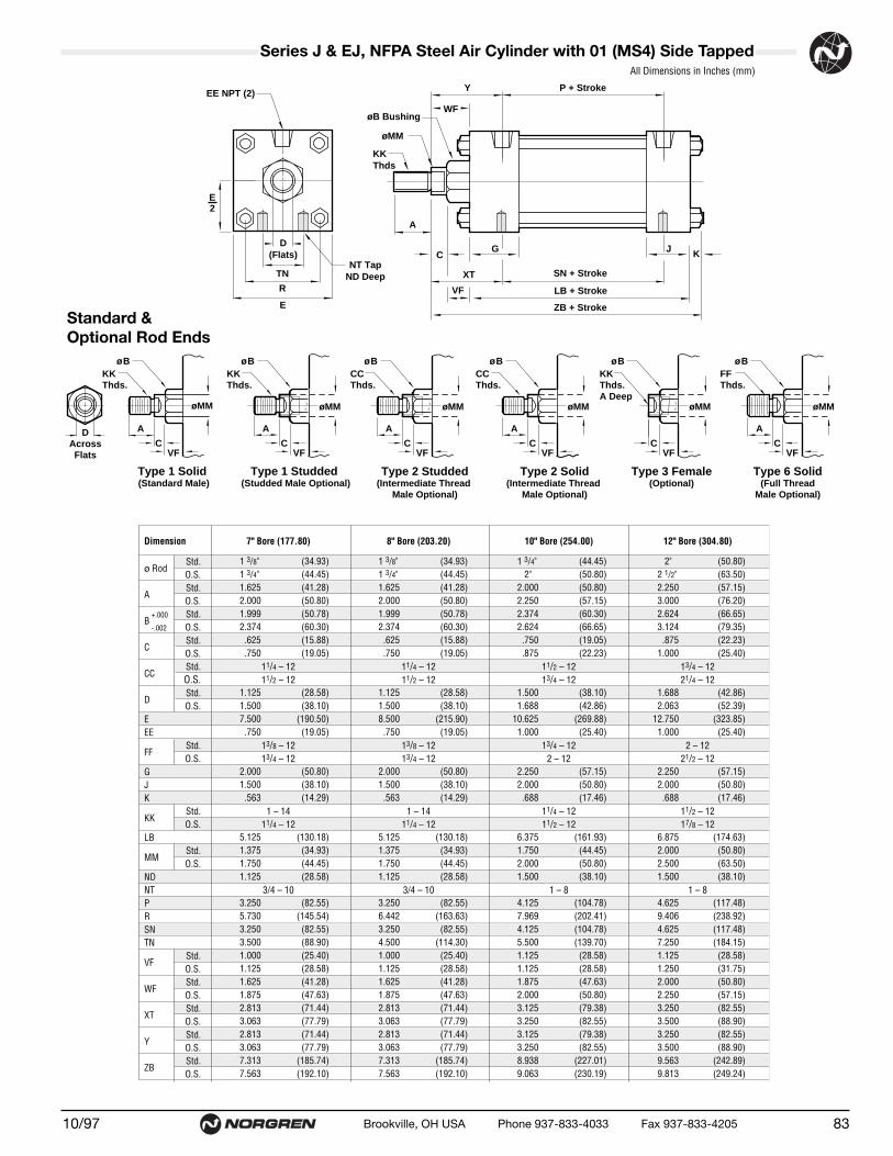
Dimension 11/2" Bore (38.10) 2" Bore (50.80) 21/2" Bore (63.50) 31/4" Bore (82.55) 4" Bore (101.60) 5" Bore (127.00) 6" Bore (152.40) 7" Bore (177.80) 8" Bore (
ø RodStd.O.S.
A Std.O.S.
B+.000 Std.-.002 O.S.
CStd.O.S.
CCStd. 1/2 – 20 1/2 – 20 1/2 – 20 7/8 – 14 7/8 – 14 7/8 – 14 11/4 – 12 11/4 – 12 11/4O.S. 7/8 – 14 7/8 – 14 7/8 – 14 11/4 – 12 11/4 – 12 11/4 – 12 11/2 – 12 11/2 – 12 11/2
DStd.O.S.
EEE
FFStd. 5/8 – 18 5/8 – 18 5/8 – 18 1 – 14 1 – 14 1 – 14 13/8 – 12 13/8 – 12 13/8O.S. 1 – 14 1 – 14 1 – 14 13/8 – 12 13/8 – 12 13/8 – 12 13/4 – 12 13/4 – 12 13/4
GJK
KK Std. 7/16 – 20 7/16 – 20 7/16 – 20 3/4 – 16 3/4 – 16 3/4 – 16 1 – 14 1 – 14 1 –O.S. 3/4 – 16 3/4 – 16 3/4 – 16 1 – 14 1 – 14 1 – 14 11/4 – 12 11/4 – 12 11/4
LB
MMStd.O.S.
NDNT 1/4 – 20 5/16 – 18 3/8 – 16 1/2 – 13 1/2 – 13 5/8 – 11 3/4 – 10 3/4 – 10 3/4 –PRSNTN
VFStd.O.S.
WFStd.O.S.
XTStd.O.S.
Y Std.O.S.
ZBStd.O.S.
(15.88) (15.88) (15.88) (25.40) (25.40) (25.40) (34.93) (34.93)(25.40) (25.40) (25.40) (34.93) (34.93) (34.93) (44.45) (44.45)(19.05) (19.05) (19.05) (28.58) (28.58) (28.58) (41.28) (41.28)(28.58) (28.58) (28.58) (41.28) (41.28) (41.28) (50.80) (50.80)(28.55) (28.55) (28.55) (38.08) (38.08) (38.08) (50.78) (50.78)(38.08) (38.08) (38.08) (50.78) (50.78) (50.78) (60.30) (60.30)(9.53) (9.53) (9.53) (12.70) (12.70) (12.70) (15.88) (15.88)
(12.70) (12.70) (12.70) (15.88) (15.88) (15.88) (19.05) (19.05)
(12.70) (12.70) (12.70) (20.64) (20.64) (20.64) (28.58) (28.58)(20.64) (20.64) (20.64) (28.58) (28.58) (28.58) (38.10) (38.10)(50.80) (63.50) (76.20) (95.25) (114.30) (139.70) (165.10) (190.50)(9.53) (9.53) (9.53) (12.70) (12.70) (12.70) (19.05) (19.05)
(38.10) (38.10) (38.10) (44.45) (44.45) (44.45) (50.80) (50.80)(25.40) (25.40) (25.40) (31.75) (31.75) (31.75) (38.10) (38.10)(6.35) (7.94) (7.94) (9.53) (9.53) (11.11) (11.11) (14.29)
(92.08) (92.08) (95.25) (107.95) (107.95) (114.30) (127.00) (130.18)(15.88) (15.88) (15.88) (25.40) (25.40) (25.40) (34.93) (34.93)(25.40) (25.40) (25.40) (34.93) (34.93) (34.93) (44.45) (44.45)(9.53) (9.53) (12.70) (19.05) (19.05) (23.81) (28.58) (28.58)
(58.74) (58.74) (61.91) (66.68) (66.68) (73.03) (79.38) (82.55)(36.27) (46.68) (55.67) (70.05) (84.40) (104.16) (123.92) (145.54)(57.15) (57.15) (60.33) (66.68) (66.68) (73.03) (79.38) (82.55)(15.88) (22.23) (31.75) (38.10) (52.37) (68.28) (82.55) (88.90)(15.88) (15.88) (15.88) (22.23) (22.23) (22.23) (25.40) (25.40)(22.23) (22.23) (22.23) (25.40) (25.40) (25.40) (28.58) (28.58)(25.40) (25.40) (25.40) (34.93) (34.93) (34.93) (41.28) (41.28)(34.93) (34.93) (34.93) (41.28) (41.28) (41.28) (47.63) (47.63)(49.21) (49.21) (49.21) (61.91) (61.91) (61.91) (71.44) (71.44)(58.74) (58.74) (58.74) (68.26) (68.26) (68.26) (77.79) (77.79)(47.63) (47.63) (47.63) (61.91) (61.91) (61.91) (71.44) (71.44)(57.15) (57.15) (57.15) (68.26) (68.26) (68.26) (77.79) (77.79)
(123.83) (125.41) (128.59) (152.40) (152.40) (160.34) (179.39) (185.74)(133.35) (134.94) (138.11) (158.75) (158.75) (166.69) (185.74) (192.10)
8110/97 Brookville, OH USA Phone 937-833-4033 Fax 937-833-4205
Series J & EJ, NFPA Steel Air Cylinder with 01 (MS4) Side Tapped
Standard & Optional Rod Ends
All Dimensions in Inches (mm)
CCThds.
A
ø B
øMM
A
øMM
ø BKK Thds.
KKThds.A Deep
ø B
øMM
CCThds.
A
ø B
øMM
FFThds.
ø B
øMM
Type 2 Studded(Intermediate Thread
Male Optional)
Type 3 Female(Optional)
Type 2 Solid(Intermediate Thread
Male Optional)
Type 6 Solid(Full Thread
Male Optional)
DAcrossFlats
A
øMM
ø BKK Thds.
Type 1 Studded (Studded Male Optional)
Type 1 Solid (Standard Male)
CVF
CVF
CVF
CVF
CVF
A
CVF
D(Flats)
EE NPT (2)
R
E
A
CG
ZB + Stroke
LB + Stroke
J K
P + StrokeY
øB Bushing
øMM
KKThds
WF
NT TapND DeepTN SN + StrokeXT
VF
E2

● NFPA (MS4) 01 Side Tapped Mountfor 7" to 12" bore sizes.
● Series J Cylinders rated to 250 PSI air,400 PSI hydraulic (non-shock).
Series EJ Cylinders rated to 250 PSI air only.
● Designed for non-lube service.
● Switches available on all bore sizes.(See pages 150 & 151 for ordering information.)
Series J & EJ, NFPA Steel Air Cylinders (ø11/2" to 12")
Cylinder with 01 (MS4) Side Tapped
10/9782 Brookville, OH USA Phone 937-833-4033 Fax 937-833-4205
See page 156 for complete instructions on how to order cylinders.
1
3
4 2
Port and Cushion AdjustmentPositions (As viewed from rod end:Port standard position 1, CushionAdjustment standard position 2.)NOTE: A Port and a Cushion Adjustmentcannot be in the same position.
Additional Options – order alphabetically – More on page 155HR Case Hardened (45 Rc)L(_ _) Port Location position 1 standard: L(Head Cap)
(specify position 1 thru 4 for head and/or cap)MS Metal Rod ScraperN(_ _) Cushion Adjust Screw Location position 2 standard: N(Head
Cap) (specify position 1 thru 4 for head and/or cap)P(_)* Non-Standard Port Sizes: [specify port size for P(_H) head
only, P(_C) cap only, or P(_) both head & cap]PS Magnetic Piston – includes aluminum tube optionRS Rod Stud
Type 1 (5/8" – 13/4" øRod)Type 2 (5/8" & 1" øRod)
RX Rod Extensions (specify length of additional rod extension)SC Single Acting Spring Extend (Cap End)–See page 155SR Single Acting Spring Retract (Rod End)–See page 155SS 303 Stainless Steel (Hard Chrome Plated)ST(_C) Stop Tube (Cap End) (specify stop tube length)ST(_R) Stop Tube (Rod End) (specify stop tube length) T Special Rod Threads (specify rod thread)TX Thread Extensions (specify length of thread extension)V Viton® Seals
*11/2", 2", 21/2" bore cylinders have 3/8" NPT Standard, 1/2" NPT oversize. 31/4", 4", 5" bore cylinders have 1/2" NPT Standard, 3/4" NPT oversize.This will add 1/8" to the overall cylinder length.
Mounting Options01 Side Tapped (MS4)03 Head Rectangular Flange (MF1)03 Head Square (ME3)–7" to 12" Bores04 Cap Rectangular Flange (MF2)04 Cap Square (ME4)–7" to 12" Bores05 Basic Cylinder No Mounting (MX0)06 Both Ends (4) Tie Rods Ext. (MX1)6B Both Ends (2) Tie Rods Ext. (MX4)6C Cap Tie Rods Ext. (MX2)6R Head Tie Rods Ext. (MX3)07 Head Trunnion (MT1)08 Cap Trunnion (MT2)09 Side Lugs (MS2)10 Center Trunnion (MT4)11 Side End Angles (MS1)12 Cap Fixed Clevis (MP1)15 Side End Lugs (MS7)16 Sleeve Nut Construction (Universal)20 Head Square Flange (MF5)21 Cap Square Flange (MF6)22 Detachable Cap Clevis (MP2)32 Cap Fixed Eye (MP3)42 Detachable Cap Eye (MP4)52 Spherical Bearing
J Series J CylinderEJ Series EJ Cylinder
Cylinder Order Information
01 – – – –
Bore and Stroke (write out )
Piston Rod DiametersA 5/8" Standard on 11/2", 2", 21/2"
Standard on 31/4", 4", 5"B 1"
Oversized on 11/2", 2", 21/2"Standard on 6", 7", 8"
C 13/8"Oversized on 31/4", 4", 5"Standard on 10"
D 13/4"Oversized on 6", 7", 8"Standard on 12"
E 2"Oversized on 10"
F 21/2" Oversized on 10", 12"
†Standard with EJ
†Standard with EJ
Cushion in Head 3 None5† Non-Adjustable Cushion7 Adjustable Cushion (Position 2)
Cushion in Cap 3 None5† Non-Adjustable Cushion7 Adjustable Cushion (Position 2)
Piston Rod Threads Type1 Small Male (Solid)2 Intermediate Thread Male (Solid)3 Female6 Full Thread Male (Solid)7 Plain Rod End
(34.93) (34.93) (44.45) (50.80)(44.45) (44.45) (50.80) (63.50)(41.28) (41.28) (50.80) (57.15)(50.80) (50.80) (57.15) (76.20)(50.78) (50.78) (60.30) (66.65)(60.30) (60.30) (66.65) (79.35)(15.88) (15.88) (19.05) (22.23)(19.05) (19.05) (22.23) (25.40)
(28.58) (28.58) (38.10) (42.86)(38.10) (38.10) (42.86) (52.39)
(190.50) (215.90) (269.88) (323.85)(19.05) (19.05) (25.40) (25.40)
(50.80) (50.80) (57.15) (57.15)(38.10) (38.10) (50.80) (50.80)(14.29) (14.29) (17.46) (17.46)
(130.18) (130.18) (161.93) (174.63)(34.93) (34.93) (44.45) (50.80)(44.45) (44.45) (50.80) (63.50)(28.58) (28.58) (38.10) (38.10)
(82.55) (82.55) (104.78) (117.48)(145.54) (163.63) (202.41) (238.92)(82.55) (82.55) (104.78) (117.48)(88.90) (114.30) (139.70) (184.15)(25.40) (25.40) (28.58) (28.58)(28.58) (28.58) (28.58) (31.75)(41.28) (41.28) (47.63) (50.80)(47.63) (47.63) (50.80) (57.15)(71.44) (71.44) (79.38) (82.55)(77.79) (77.79) (82.55) (88.90)(71.44) (71.44) (79.38) (82.55)(77.79) (77.79) (82.55) (88.90)
(185.74) (185.74) (227.01) (242.89)(192.10) (192.10) (230.19) (249.24)
1.3/8" 1.3/8" 1.3/4" .2"1.3/4" 1.3/4" .2" 2.1/2"1.625 1.625 2.000 2.2502.000 2.000 2.250 3.0001.999 1.999 2.374 2.6242.374 2.374 2.624 3.124.625 .625 .750 .875.750 .750 .875 1.000
1.125 1.125 1.500 1.6881.500 1.500 1.688 2.0637.500 8.500 10.625 12.750.750 .750 1.000 1.000
2.000 2.000 2.250 2.2501.500 1.500 2.000 2.000.563 .563 .688 .688
5.125 5.125 6.375 6.8751.375 1.375 1.750 2.0001.750 1.750 2.000 2.5001.125 1.125 1.500 1.500
3.250 3.250 4.125 4.6255.730 6.442 7.969 9.4063.250 3.250 4.125 4.6253.500 4.500 5.500 7.2501.000 1.000 1.125 1.1251.125 1.125 1.125 1.2501.625 1.625 1.875 2.0001.875 1.875 2.000 2.2502.813 2.813 3.125 3.2503.063 3.063 3.250 3.5002.813 2.813 3.125 3.2503.063 3.063 3.250 3.5007.313 7.313 8.938 9.5637.563 7.563 9.063 9.813
Dimension 7" Bore (177.80) 8" Bore (203.20) 10" Bore (254.00) 12" Bore (304.80)
ø RodStd.O.S.
A Std.O.S.
B+.000 Std.-.002 O.S.
CStd.O.S.
CCStd. 11/4 – 12 11/4 – 12 11/2 – 12 13/4 – 12O.S. 11/2 – 12 11/2 – 12 13/4 – 12 21/4 – 12
DStd.O.S.
EEE
FFStd. 13/8 – 12 13/8 – 12 13/4 – 12 2 – 12O.S. 13/4 – 12 13/4 – 12 2 – 12 21/2 – 12
GJK
KK Std. 1 – 14 1 – 14 11/4 – 12 11/2 – 12O.S. 11/4 – 12 11/4 – 12 11/2 – 12 17/8 – 12
LB
MMStd.O.S.
NDNT 3/4 – 10 3/4 – 10 1 – 8 1 – 8PRSNTN
VFStd.O.S.
WFStd.O.S.
XTStd.O.S.
Y Std.O.S.
ZBStd.O.S.
8310/97 Brookville, OH USA Phone 937-833-4033 Fax 937-833-4205
Series J & EJ, NFPA Steel Air Cylinder with 01 (MS4) Side Tapped
Standard & Optional Rod Ends
All Dimensions in Inches (mm)
CCThds.
A
ø B
øMM
A
øMM
ø BKK Thds.
KKThds.A Deep
ø B
øMM
CCThds.
A
ø B
øMM
FFThds.
ø B
øMM
Type 2 Studded(Intermediate Thread
Male Optional)
Type 3 Female(Optional)
Type 2 Solid(Intermediate Thread
Male Optional)
Type 6 Solid(Full Thread
Male Optional)
DAcrossFlats
A
øMM
ø BKK Thds.
Type 1 Studded (Studded Male Optional)
Type 1 Solid (Standard Male)
CVF
CVF
CVF
CVF
CVF
A
CVF
D(Flats)
EE NPT (2)
R
E
A
CG
ZB + Stroke
LB + Stroke
J K
P + StrokeY
øB Bushing
øMM
KKThds
WF
NT TapND DeepTN SN + StrokeXT
VF
E2

● NFPA (MF1) 03 Head Rectangular Flange Mount for 1-1/2" to 6" bore sizes.
● Series J Cylinders rated to 250 PSI air,400 PSI hydraulic (non-shock).
Series EJ Cylinders rated to 250 PSI air only.
● Designed for non-lube service.
● Switches available on all bore sizes.(See pages 150 & 151 for ordering information.)
Series J & EJ, NFPA Steel Air Cylinders (ø11/2" to 6")
Cylinder with 03 (MF1) Head Rectangular Flange
10/9784 Brookville, OH USA Phone 937-833-4033 Fax 937-833-4205
See page 156 for complete instructions on how to order cylinders.
1
3
4 2
Port and Cushion AdjustmentPositions (As viewed from rod end:Port standard position 1, CushionAdjustment standard position 2.)NOTE: A Port and a Cushion Adjustmentcannot be in the same position.
Additional Options – order alphabetically – More on page 155HR Case Hardened (45 Rc)L(_ _) Port Location position 1 standard: L(Head Cap)
(specify position 1 thru 4 for head and/or cap)MS Metal Rod ScraperN(_ _) Cushion Adjust Screw Location position 2 standard: N(Head
Cap) (specify position 1 thru 4 for head and/or cap)P(_)* Non-Standard Port Sizes: [specify port size for P(_H) head
only, P(_C) cap only, or P(_) both head & cap]PS Magnetic Piston – includes aluminum tube optionRS Rod Stud
Type 1 (5/8" – 13/4" øRod)Type 2 (5/8" & 1" øRod)
RX Rod Extensions (specify length of additional rod extension)SC Single Acting Spring Extend (Cap End)–See page 155SR Single Acting Spring Retract (Rod End)–See page 155SS 303 Stainless Steel (Hard Chrome Plated)ST(_C) Stop Tube (Cap End) (specify stop tube length)ST(_R) Stop Tube (Rod End) (specify stop tube length) T Special Rod Threads (specify rod thread)TX Thread Extensions (specify length of thread extension)V Viton® Seals
*11/2", 2", 21/2" bore cylinders have 3/8" NPT Standard, 1/2" NPT oversize. 31/4", 4", 5" bore cylinders have 1/2" NPT Standard, 3/4" NPT oversize.This will add 1/8" to the overall cylinder length.
Mounting Options01 Side Tapped (MS4)03 Head Rectangular Flange (MF1)03 Head Square (ME3)–7" to 12" Bores04 Cap Rectangular Flange (MF2)04 Cap Square (ME4)–7" to 12" Bores05 Basic Cylinder No Mounting (MX0)06 Both Ends (4) Tie Rods Ext. (MX1)6B Both Ends (2) Tie Rods Ext. (MX4)6C Cap Tie Rods Ext. (MX2)6R Head Tie Rods Ext. (MX3)07 Head Trunnion (MT1)08 Cap Trunnion (MT2)09 Side Lugs (MS2)10 Center Trunnion (MT4)11 Side End Angles (MS1)12 Cap Fixed Clevis (MP1)15 Side End Lugs (MS7)16 Sleeve Nut Construction (Universal)20 Head Square Flange (MF5)21 Cap Square Flange (MF6)22 Detachable Cap Clevis (MP2)32 Cap Fixed Eye (MP3)42 Detachable Cap Eye (MP4)52 Spherical Bearing
J Series J CylinderEJ Series EJ Cylinder
Cylinder Order Information
03 – – – –
Bore and Stroke (write out )
Piston Rod DiametersA 5/8" Standard on 11/2", 2", 21/2"
Standard on 31/4", 4", 5"B 1"
Oversized on 11/2", 2", 21/2"Standard on 6", 7", 8"
C 13/8"Oversized on 31/4", 4", 5"Standard on 10"
D 13/4"Oversized on 6", 7", 8"Standard on 12"
E 2"Oversized on 10"
F 21/2" Oversized on 10", 12"
†Standard with EJ
†Standard with EJ
Cushion in Head 3 None5† Non-Adjustable Cushion7 Adjustable Cushion (Position 2)
Cushion in Cap 3 None5† Non-Adjustable Cushion7 Adjustable Cushion (Position 2)
Piston Rod Threads Type1 Small Male (Solid)2 Intermediate Thread Male (Solid)3 Female6 Full Thread Male (Solid)7 Plain Rod End

.5/8" .5/8" .5/8" .1" .1" .1" 1.3/8" 1.3/8"
.1" .1" .1" 1.3/8" 1.3/8" 1.3/8" 1.3/4" 1.3/4"
.750 .750 .750 1.125 1.125 1.125 1.625 1.6251.125 1.125 1.125 1.625 1.625 1.625 2.000 2.0001.124 1.124 1.124 1.499 1.499 1.499 1.999 1.9991.499 1.499 1.499 1.999 1.999 1.999 2.374 2.374.375 .375 .375 .500 .500 .500 .625 .625.500 .500 .500 .625 .625 .625 .750 .750
.500 .500 .500 .813 .813 .813 1.125 1.125
.813 .813 .813 1.125 1.125 1.125 1.500 1.5002.000 2.500 3.000 3.750 4.500 5.500 6.500 8.500.375 .375 .375 .500 .500 .500 .750 .750.375 .375 .375 .625 .625 .625 .750.313 .375 .375 .438 .438 .563 .563 .687
1.500 1.500 1.500 1.750 1.750 1.750 2.000 2.0001.000 1.000 1.000 1.250 1.250 1.250 1.500 1.500.250 .313 .313 .375 .375 .438 .438 .563
3.625 3.625 3.750 4.250 4.250 4.500 5.000 5.125.625 .625 .625 1.000 1.000 1.000 1.375 1.355
1.000 1.000 1.000 1.375 1.375 1.375 1.750 1.7302.313 2.313 2.438 2.625 2.625 2.875 3.125 3.2501.428 1.838 2.192 2.758 3.323 4.101 4.879 6.4352.750 3.375 3.875 4.688 5.438 6.625 7.6253.375 4.125 4.625 5.500 6.250 7.625 8.625.250 .250 .250 .250 .250 .250 .250 .375.500 .500 .500 .375 .375 .375 .375 .375.625 .625 .625 .750 .750 .750 .875 1.625
1.000 1.000 1.000 1.000 1.000 1.000 1.125 1.8751.000 1.000 1.000 1.375 1.375 1.375 1.6251.375 1.375 1.375 1.625 1.625 1.625 1.8751.875 1.875 1.875 2.438 2.438 2.438 2.813 2.8132.250 2.250 2.250 2.688 2.688 2.688 3.063 3.0634.875 4.938 5.063 6.000 6.000 6.313 7.063 7.3135.250 5.313 5.438 6.250 6.250 6.563 7.313 7.625
Dimension 11/2" Bore (38.10) 2" Bore (50.80) 21/2" Bore (63.50) 31/4" Bore (82.55) 4" Bore (101.60) 5" Bore (127.00) 6" Bore (152.40) 8" Bore (203.20)
ø RodStd.O.S.
A Std.O.S.
B+.000 Std.-.002 O.S.
CStd.O.S.
CCStd. 1/2 – 20 1/2 – 20 1/2 – 20 7/8 – 14 7/8 – 14 7/8 – 14 11/4 – 12 11/4 – 12O.S. 7/8 – 14 7/8 – 14 7/8 – 14 11/4 – 12 11/4 – 12 11/4 – 12 11/2 – 12 11/2 – 12
DStd.O.S.
EEEF –FB
FFStd. 5/8 – 18 5/8 – 18 5/8 – 18 1 – 14 1 – 14 1 – 14 13/8 – 12 13/8 – 12O.S. 1 – 14 1 – 14 1 – 14 13/8 – 12 13/8 – 12 13/8 – 12 13/4 – 12 13/4 – 12
GJK
KK Std. 7/16 – 20 7/16 – 20 7/16 – 20 3/4 – 16 3/4 – 16 3/4 – 16 1 – 14 1 – 14O.S. 3/4 –16 3/4 –16 3/4 –16 1 – 14 1 – 14 1 – 14 11/4 – 12 11/4 – 12
LB
MMStd.O.S.
PRTF –UF –
VStd.O.S.
WStd.O.S.
WFStd. –O.S. –
Y Std.O.S.
ZBStd.O.S.
(15.88) (15.88) (15.88) (25.40) (25.40) (25.40) (34.93) (34.93)(25.40) (25.40) (25.40) (34.93) (34.93) (34.93) (44.45) (44.45)(19.05) (19.05) (19.05) (28.58) (28.58) (28.58) (41.28) (41.28)(28.58) (28.58) (28.58) (41.28) (41.28) (41.28) (50.80) (50.80)(28.55) (28.55) (28.55) (38.08) (38.08) (38.08) (50.78) (50.78)(38.08) (38.08) (50.78) (50.78) (50.78) (60.30) (60.30) (60.30)(9.53) (9.53) (9.53) (12.70) (12.70) (12.70) (15.88) (15.88)
(12.70) (12.70) (12.70) (15.88) (15.88) (15.88) (19.05) (19.05)
(12.70) (12.70) (12.70) (20.64) (20.64) (20.64) (28.58) (28.58)(20.64) (20.64) (20.64) (28.58) (28.58) (28.58) (38.10) (38.10)(50.80) (63.50) (76.20) (95.25) (114.30) (139.70) (165.10) (215.90)(9.53) (9.53) (9.53) (12.70) (12.70) (12.70) (19.05) (19.05)(9.53) (9.53) (9.53) (15.88) (15.88) (15.88) (19.05)(7.94) (9.53) (9.53) (11.11) (11.11) (14.29) (14.29) (17.45)
(38.10) (38.10) (38.10) (44.45) (44.45) (44.45) (50.80) (50.80)(25.40) (25.40) (25.40) (31.75) (31.75) (31.75) (38.10) (38.10)(6.35) (7.94) (7.94) (9.53) (9.53) (11.11) (11.11) (14.29)
(92.08) (92.08) (95.25) (107.95) (107.95) (114.30) (127.00) (130.18)(15.88) (15.88) (15.88) (25.40) (25.40) (25.40) (34.93) (34.42)(25.40) (25.40) (25.40) (34.93) (34.93) (34.93) (44.45) (43.94)(58.74) (58.74) (61.91) (66.68) (66.68) (73.03) (79.38) (79.38)(36.27) (46.68) (55.67) (70.05) (84.40) (104.16) (123.92) (163.44)(69.85) (85.73) (98.43) (119.06) (138.11) (168.28) (193.68)(85.73) (104.78) (117.48) (139.70) (158.75) (193.68) (219.08)(6.35) (6.35) (6.35) (6.35) (6.35) (6.35) (6.35) (9.53)
(12.70) (12.70) (12.70) (9.53) (9.53) (9.53) (9.53) (9.53)(15.88) (15.88) (15.88) (19.05) (19.05) (19.05) (22.23) (41.28)(25.40) (25.40) (25.40) (25.40) (25.40) (25.40) (28.58) (47.63)(25.40) (25.40) (25.40) (34.93) (34.93) (34.93) (41.27)(34.93) (34.93) (34.93) (41.27) (41.27) (41.27) (47.63)(47.63) (47.63) (47.63) (61.91) (61.91) (61.91) (71.44) (71.44)(57.15) (57.15) (57.15) (68.26) (68.26) (68.26) (77.79) (77.79)
(123.83) (125.41) (128.59) (152.40) (152.40) (160.34) (179.39) (185.74)(133.35) (134.94) (138.11) (158.75) (158.75) (166.69) (185.74) (193.68)
8510/97 Brookville, OH USA Phone 937-833-4033 Fax 937-833-4205
Series J & EJ, NFPA Steel Air Cylinder with 03 (MF1) Head Rectangular FlangeAll Dimensions in Inches (mm)
Standard &Optional Rod Ends
Type 2 Studded(Intermediate Thread
Male Optional)
Type 1 Studded (Studded Male Optional)
Type 3 Female(Optional)
Type 2 Solid(Intermediate Thread
Male Optional)
Type 6 Solid(Full Thread
Male Optional)
CCThds.
A
øB
øMM
F
A
øMM
øBKK Thds.
F KKThds.A Deep
øB
øMM
FCCThds.
A
øB
øMM
F FFThds.
A
øB
øMM
F
DAcrossFlats
A
øMM
Fø B
KK Thds.
Type 1 Solid (Standard Male)
VC
VC
VC
VC
VC
VC
R
C
V
G
ZB + Stroke
LB + Stroke
JK
P + StrokeYøB Bushing
øMM
KKThds
EE NPT(2)FB Holes (4)
E
D(Flats)
TF
UFF
A
W
WFR
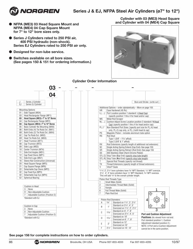
● NFPA (ME3) 03 Head Square Mount and NFPA (ME4) 04 Cap Square Mountfor 7" to 12" bore sizes only.
● Series J Cylinders rated to 250 PSI air,400 PSI hydraulic (non-shock).
Series EJ Cylinders rated to 250 PSI air only.
● Designed for non-lube service.
● Switches available on all bore sizes.(See pages 150 & 151 for ordering information.)
Series J & EJ, NFPA Steel Air Cylinders (ø7" to 12")
Cylinder with 03 (ME3) Head Squareand Cylinder with 04 (ME4) Cap Square
10/9786 Brookville, OH USA Phone 937-833-4033 Fax 937-833-4205
See page 156 for complete instructions on how to order cylinders.
1
3
4 2
Port and Cushion AdjustmentPositions (As viewed from rod end:Port standard position 1, CushionAdjustment standard position 2.)NOTE: A Port and a Cushion Adjustmentcannot be in the same position.
Additional Options – order alphabetically – More on page 155HR Case Hardened (45 Rc)L(_ _) Port Location position 1 standard: L(Head Cap)
(specify position 1 thru 4 for head and/or cap)MS Metal Rod ScraperN(_ _) Cushion Adjust Screw Location position 2 standard: N(Head
Cap) (specify position 1 thru 4 for head and/or cap)P(_)* Non-Standard Port Sizes: [specify port size for P(_H) head
only, P(_C) cap only, or P(_) both head & cap]PS Magnetic Piston – includes aluminum tube optionRS Rod Stud
Type 1 (5/8" – 13/4" øRod)Type 2 (5/8" & 1" øRod)
RX Rod Extensions (specify length of additional rod extension)SC Single Acting Spring Extend (Cap End)–See page 155SR Single Acting Spring Retract (Rod End)–See page 155SS 303 Stainless Steel (Hard Chrome Plated)ST(_C) Stop Tube (Cap End) (specify stop tube length)ST(_R) Stop Tube (Rod End) (specify stop tube length) T Special Rod Threads (specify rod thread)TX Thread Extensions (specify length of thread extension)V Viton® Seals
*11/2", 2", 21/2" bore cylinders have 3/8" NPT Standard, 1/2" NPT oversize. 31/4", 4", 5" bore cylinders have 1/2" NPT Standard, 3/4" NPT oversize.This will add 1/8" to the overall cylinder length.
Mounting Options01 Side Tapped (MS4)03 Head Rectangular Flange (MF1)03 Head Square (ME3)–7" to 12" Bores04 Cap Rectangular Flange (MF2)04 Cap Square (ME4)–7" to 12" Bores05 Basic Cylinder No Mounting (MX0)06 Both Ends (4) Tie Rods Ext. (MX1)6B Both Ends (2) Tie Rods Ext. (MX4)6C Cap Tie Rods Ext. (MX2)6R Head Tie Rods Ext. (MX3)07 Head Trunnion (MT1)08 Cap Trunnion (MT2)09 Side Lugs (MS2)10 Center Trunnion (MT4)11 Side End Angles (MS1)12 Cap Fixed Clevis (MP1)15 Side End Lugs (MS7)16 Sleeve Nut Construction (Universal)20 Head Square Flange (MF5)21 Cap Square Flange (MF6)22 Detachable Cap Clevis (MP2)32 Cap Fixed Eye (MP3)42 Detachable Cap Eye (MP4)52 Spherical Bearing
J Series J CylinderEJ Series EJ Cylinder
Cylinder Order Information
0304
– – – –
Bore and Stroke (write out )
Piston Rod DiametersA 5/8" Standard on 11/2", 2", 21/2"
Standard on 31/4", 4", 5"B 1"
Oversized on 11/2", 2", 21/2"Standard on 6", 7", 8"
C 13/8"Oversized on 31/4", 4", 5"Standard on 10"
D 13/4"Oversized on 6", 7", 8"Standard on 12"
E 2"Oversized on 10"
F 21/2" Oversized on 10", 12"
†Standard with EJ
†Standard with EJ
Cushion in Head 3 None5† Non-Adjustable Cushion7 Adjustable Cushion (Position 2)
Cushion in Cap 3 None5† Non-Adjustable Cushion7 Adjustable Cushion (Position 2)
Piston Rod Threads Type1 Small Male (Solid)2 Intermediate Thread Male (Solid)3 Female6 Full Thread Male (Solid)7 Plain Rod End

(34.93) (34.93) (44.45) (50.80) (34.93) (34.93) (44.45) (50.80)(44.45) (44.45) (50.80) (63.50) (44.45) (44.45) (50.80) (63.50)(41.28) (41.28) (50.80) (57.15) (41.28) (41.28) (50.80) (57.15)(50.80) (50.80) (57.15) (76.20) (50.80) (50.80) (57.15) (76.20)(50.78) (50.78) (60.30) (66.65) (50.78) (50.78) (60.30) (66.65)(60.30) (60.30) (66.65) (79.35) (60.30) (60.30) (66.65) (79.35)(15.88) (15.88) (19.05) (22.23) (15.88) (15.88) (19.05) (22.23)(19.05) (19.05) (22.23) (25.40) (19.05) (19.05) (22.23) (25.40)
(28.58) (28.58) (38.10) (42.86) (28.58) (28.58) (38.10 (42.86)(38.10) (38.10) (42.86) (52.39) (38.10) (38.10) (42.86) (52.39)
(190.50) (215.90) (269.88) (323.85) (190.50) (215.90) (269.88) (323.85)(14.29) (17.46) (20.64) (20.64) (14.29) (17.46) (20.64) (20.64)(19.05) (19.05) (25.40) (25.40) (19.05) (19.05) (25.40) (25.40)
(50.80) (50.80) (57.15) (57.15) (50.80) (50.80) (57.15) (57.15)(38.10) (38.10) (50.80) (50.80) (38.10) (38.10) (50.80) (50.80)(14.29) (14.29) (17.46) (17.46) (14.29) (14.29) (17.46) (17.46)
(130.18) (130.18) (161.93) (174.63) (130.18) (130.18) (161.93) (174.63)(34.93) (34.93) (44.45) (50.80) (34.93) (34.93) (44.45) (50.80)(44.45) (44.45) (50.80) (63.50) (44.45) (44.45) (50.80) (63.50)(82.55) (82.55) (104.78) (117.48) (82.55) (82.55) (104.78) (117.48)
(145.54) (163.63) (202.41) (238.92) (145.54) (163.63) (202.41) (238.92)(171.45) (192.27) (238.92) (282.18) (171.45) (192.27) (238.92) (282.18)(25.40) (25.40) (28.58) (28.58) (25.40) (25.40) (28.58) (28.58)(28.58) (28.58) (28.58) (31.75) (28.58) (28.58) (28.58) (31.75)(41.28) (41.28) (47.63) (50.80) (41.28) (41.28) (47.63) (50.80)(47.63) (47.63) (50.80) (57.15) (47.63) (47.63) (50.80) (57.15)(71.44) (71.44) (79.38) (82.55) (71.44) (71.44) (79.38) (82.55)(77.79) (77.79) (82.55) (88.90) (77.79) (77.79) (82.55) (88.90)
(185.74) (185.74) (227.01) (242.89)(192.09) (192.09) (230.19) (249.24)
(171.45) (171.45) (209.55) (225.43)(177.80) (177.80) (212.73) (231.78)
1.3/8" 1.3/8" 1.3/4" .2" 1.3/8" 1.3/8" 1.3/4" .2"1.3/4" 1.3/4" .2" 2.1/2" 1.3/4" 1.3/4" .2" 2.1/2"1.625 1.625 2.000 2.250 1.625 1.625 2.000 2.2502.000 2.000 2.250 3.000 2.000 2.000 2.250 3.0001.999 1.999 2.374 2.624 1.999 1.999 2.374 2.6242.374 2.374 2.624 3.124 2.374 2.374 2.624 3.124.625 .625 .750 .875 .625 .625 .750 .875.750 .750 .875 1.000 .750 .750 .875 1.000
1.125 1.125 1.500 1.688 1.125 1.125 1.500 1.6881.500 1.500 1.688 2.063 1.500 1.500 1.688 2.0637.500 8.500 10.625 12.750 7.500 8.500 10.625 12.750.563 .688 .813 .813 .563 .688 .813 .813.750 .750 1.000 1.000 .750 .750 1.000 1.000
2.000 2.000 2.250 2.250 2.000 2.000 2.250 2.2501.500 1.500 2.000 2.000 1.500 1.500 2.000 2.000.563 .563 .688 .688 .563 .563 .688 .688
5.125 5.125 6.375 6.875 5.125 5.125 6.375 6.8751.375 1.375 1.750 2.000 1.375 1.375 1.750 2.0001.750 1.750 2.000 2.500 1.750 1.750 2.000 2.5003.250 3.250 4.125 4.625 3.250 3.250 4.125 4.6255.730 6.442 7.969 9.406 5.730 6.442 7.969 9.4066.750 7.570 9.406 11.109 6.750 7.570 9.406 11.1091.000 1.000 1.125 1.125 1.000 1.000 1.125 1.1251.125 1.125 1.125 1.250 1.125 1.125 1.125 1.2501.625 1.625 1.875 2.000 1.625 1.625 1.875 2.0001.875 1.875 2.000 2.250 1.875 1.875 2.000 2.2502.813 2.813 3.125 3.250 2.813 2.813 3.125 3.2503.063 3.063 3.250 3.500 3.063 3.063 3.250 3.5007.313 7.313 8.938 9.5637.563 7.563 9.063 9.813
6.750 6.750 8.250 8.8757.000 7.000 8.375 9.125
03 (ME3) Head Square 04 (ME4) Cap Square Dimension 7" Bore (177.80) 8" Bore (203.20) 10" Bore (254.00) 12" Bore (304.80) 7" Bore (177.80) 8" Bore (203.20) 10" Bore (254.00) 12" Bore (304.80)
ø RodStd.O.S.
AStd.O.S.
B +.000 Std.-.002 O.S.
CStd.O.S.
CCStd. 11/4 – 12 11/4 – 12 11/2 – 12 13/4 – 12 11/4 – 12 11/4 – 12 11/2 – 12 13/4 – 12O.S. 11/2 – 12 11/2 – 12 13/4 – 12 21/4 – 12 11/2 – 12 11/2 – 12 13/4 – 12 21/4 – 12
DStd.O.S.
EEBEE
FFStd. 13/8 – 12 13/8 – 12 13/4 – 12 2 – 12 13/8 – 12 13/8 – 12 13/4 – 12 2 – 12O.S. 13/4 – 12 13/4 – 12 2 – 12 21/2 – 12 13/4 – 12 13/4 – 12 2 – 12 21/2 – 12
GJK
KK Std. 1 – 14 1 – 14 11/4 – 12 11/2 – 12 1 – 14 1 – 14 11/4 – 12 11/2 – 12O.S. 11/4 – 12 11/4 – 12 11/2 – 12 17/8 – 12 11/4 – 12 11/4 – 12 11/2 – 12 17/8 – 12
LB
MMStd.O.S.
PRTE
VFStd.O.S.
WFStd.O.S.
Y Std.O.S.
ZBStd. – – – –O.S. – – – –
ZJStd. – – – –O.S. – – – –
8710/97 Brookville, OH USA Phone 937-833-4033 Fax 937-833-4205
Series J & EJ Cylinder with 03 (ME3) Head Square & 04 (ME4) Cap Square
D(Flats)
EE NPT (2)
TEE
EB Holes (4)
R
E2 A
C
VF
G
ZB + StrokeLB + Stroke
JK
P + StrokeYøB Bushing
øMMKKThds
P + StrokeYøB Bushing
A
C
VF
G
ZJ + StrokeLB + Stroke
J
øMMKKThds
EE NPT (2)
ETE
EB Holes (4)
R
Standard & Optional Rod Ends
04 (ME4) 03 (ME3) All Dimensions in Inches (mm)
CCThds.
A
ø B
øMM
A
øMM
ø BKK Thds.
KKThds.A Deep
ø B
øMM
CCThds.
A
ø B
øMM
FFThds.
ø B
øMM
Type 2 Studded(Intermediate Thread
Male Optional)
Type 3 Female(Optional)
Type 2 Solid(Intermediate Thread
Male Optional)
Type 6 Solid(Full Thread
Male Optional)
DAcrossFlats
A
øMM
ø BKK Thds.
Type 1 Studded (Studded Male Optional)
Type 1 Solid (Standard Male)
CVF
CVF
CVF
CVF
CVF
A
CVF

● NFPA (MF2) 04 Cap Rectangular Flange Mountfor 1-1/2" to 6" bore sizes.
● Series J Cylinders rated to 250 PSI air,400 PSI hydraulic (non-shock).
Series EJ Cylinders rated to 250 PSI air only.
● Designed for non-lube service.
● Switches available on all bore sizes.(See pages 150 & 151 for ordering information.)
Series J & EJ, NFPA Steel Air Cylinders (ø11/2" to 6")
Cylinder with 04 (MF2) Cap Rectangular Flange
10/9788 Brookville, OH USA Phone 937-833-4033 Fax 937-833-4205
See page 156 for complete instructions on how to order cylinders.
1
3
4 2
Port and Cushion AdjustmentPositions (As viewed from rod end:Port standard position 1, CushionAdjustment standard position 2.)NOTE: A Port and a Cushion Adjustmentcannot be in the same position.
Additional Options – order alphabetically – More on page 155HR Case Hardened (45 Rc)L(_ _) Port Location position 1 standard: L(Head Cap)
(specify position 1 thru 4 for head and/or cap)MS Metal Rod ScraperN(_ _) Cushion Adjust Screw Location position 2 standard: N(Head
Cap) (specify position 1 thru 4 for head and/or cap)P(_)* Non-Standard Port Sizes: [specify port size for P(_H) head
only, P(_C) cap only, or P(_) both head & cap]PS Magnetic Piston – includes aluminum tube optionRS Rod Stud
Type 1 (5/8" – 13/4" øRod)Type 2 (5/8" & 1" øRod)
RX Rod Extensions (specify length of additional rod extension)SC Single Acting Spring Extend (Cap End)–See page 155SR Single Acting Spring Retract (Rod End)–See page 155SS 303 Stainless Steel (Hard Chrome Plated)ST(_C) Stop Tube (Cap End) (specify stop tube length)ST(_R) Stop Tube (Rod End) (specify stop tube length) T Special Rod Threads (specify rod thread)TX Thread Extensions (specify length of thread extension)V Viton® Seals
*11/2", 2", 21/2" bore cylinders have 3/8" NPT Standard, 1/2" NPT oversize. 31/4", 4", 5" bore cylinders have 1/2" NPT Standard, 3/4" NPT oversize.This will add 1/8" to the overall cylinder length.
Mounting Options01 Side Tapped (MS4)03 Head Rectangular Flange (MF1)03 Head Square (ME3)– 7" to 12" Bores04 Cap Rectangular Flange (MF2)04 Cap Square (ME4)– 7" to 12" Bores05 Basic Cylinder No Mounting (MX0)06 Both Ends (4) Tie Rods Ext. (MX1)6B Both Ends (2) Tie Rods Ext. (MX4)6C Cap Tie Rods Ext. (MX2)6R Head Tie Rods Ext. (MX3)07 Head Trunnion (MT1)08 Cap Trunnion (MT2)09 Side Lugs (MS2)10 Center Trunnion (MT4)11 Side End Angles (MS1)12 Cap Fixed Clevis (MP1)15 Side End Lugs (MS7)16 Sleeve Nut Construction (Universal)20 Head Square Flange (MF5)21 Cap Square Flange (MF6)22 Detachable Cap Clevis (MP2)32 Cap Fixed Eye (MP3)42 Detachable Cap Eye (MP4)52 Spherical Bearing
J Series J CylinderEJ Series EJ Cylinder
Cylinder Order Information
04 – – – –
Bore and Stroke (write out )
Piston Rod DiametersA 5/8" Standard on 11/2", 2", 21/2"
Standard on 31/4", 4", 5"B 1"
Oversized on 11/2", 2", 21/2"Standard on 6", 7", 8"
C 13/8"Oversized on 31/4", 4", 5"Standard on 10"
D 13/4"Oversized on 6", 7", 8"Standard on 12"
E 2"Oversized on 10"
F 21/2" Oversized on 10", 12"
†Standard with EJ
†Standard with EJ
Cushion in Head 3 None5† Non-Adjustable Cushion7 Adjustable Cushion (Position 2)
Cushion in Cap 3 None5† Non-Adjustable Cushion7 Adjustable Cushion (Position 2)
Piston Rod Threads Type1 Small Male (Solid)2 Intermediate Thread Male (Solid)3 Female6 Full Thread Male (Solid)7 Plain Rod End

.5/8" .5/8" .5/8" .1" .1" .1" 1.3/8" 1.3/8"
.1" .1" .1" 1.3/8" 1.3/8" 1.3/8" 1.3/4" 1.3/4"
.750 .750 .750 1.125 1.125 1.125 1.625 1.6251.125 1.125 1.125 1.625 1.625 1.625 2.000 2.0001.124 1.124 1.124 1.499 1.499 1.499 1.999 1.9991.499 1.499 1.499 1.999 1.999 1.999 2.374 2.374.375 .375 .375 .500 .500 .500 .625 .625.500 .500 .500 .625 .625 .625 .750 .750
.500 .500 .500 .813 .813 .813 1.125 1.125
.813 .813 .813 1.125 1.125 1.125 1.500 1.5002.000 2.500 3.000 3.750 4.500 5.500 6.500 8.500.375 .375 .375 .500 .500 .500 .750 .750.375 .375 .375 .625 .625 .625 .750.313 .375 .375 .438 .438 .563 .563 .687
1.500 1.500 1.500 1.750 1.750 1.750 2.000 2.0001.000 1.000 1.000 1.250 1.250 1.250 1.500 1.500.250 .313 .313 .375 .375 .438 .438 .563
3.625 3.625 3.750 4.250 4.250 4.500 5.000 5.125.625 .625 .625 1.000 1.000 1.000 1.375 1.355
1.000 1.000 1.000 1.375 1.375 1.375 1.750 1.7302.313 2.313 2.438 2.625 2.625 2.875 3.125 3.2501.428 1.838 2.192 2.758 3.323 4.101 4.879 6.4352.750 3.375 3.875 4.687 5.438 6.625 7.6253.375 4.125 4.625 5.500 6.250 7.625 8.625.625 .625 .625 .875 .875 .875 1.000 1.000.875 .875 .875 1.000 1.000 1.000 1.125 1.000
1.000 1.000 1.000 1.375 1.375 1.375 1.6251.375 1.375 1.375 1.625 1.625 1.625 1.8751.875 1.875 1.875 2.438 2.438 2.438 2.813 2.8132.250 2.250 2.313 2.688 2.688 2.688 3.063 3.0635.000 5.000 5.125 6.250 6.250 6.500 7.375 6.7505.375 5.375 5.500 6.500 6.500 6.750 7.625 7.000
Dimension 11/2" Bore (38.10) 2" Bore (50.80) 21/2" Bore (63.50) 31/4" Bore (82.55) 4" Bore (101.60) 5" Bore (127.00) 6" Bore (152.40) 8" Bore (203.20)
ø RodStd.O.S.
A Std.O.S.
B +.000 Std.-.002 O.S.
CStd.O.S.
CCStd. 1/2 – 20 1/2 – 20 1/2 – 20 7/8 –14 7/8 –14 7/8 –14 11/4 – 12 11/4 – 12O.S. 7/8 –14 7/8 –14 7/8 –14 11/4 – 12 11/4 – 12 11/4 – 12 11/2 – 12 11/2 – 12
DStd.O.S.
EEEFFB
FFStd. 5/8 – 18 5/8 – 18 5/8 – 18 1 – 14 1 – 14 1 – 14 13/8 – 12 13/8 – 12O.S. 1 – 14 1 – 14 1 – 14 13/8 – 12 13/8 – 12 13/8 – 12 13/4 – 12 13/4 – 12
GJK
KK Std. 7/16 – 20 7/16 – 20 7/16 – 20 3/4 – 16 3/4 – 16 3/4 – 16 1 – 14 1 – 14O.S. 3/4 – 16 3/4 – 16 3/4 – 16 1 – 14 1 – 14 1 – 14 11/4 – 12 11/4 – 12
LB
MMStd.O.S.
PRTF –UF –
VFStd.O.S.
WF Std.O.S.
Y Std.O.S.
ZFStd.O.S.
(15.88) (15.88) (15.88) (25.40) (25.40) (25.40) (34.93) (34.93)(25.40) (25.40) (25.40) (34.93) (34.93) (34.93) (44.45) (44.45)(19.05) (19.05) (19.05) (28.58) (28.58) (28.58) (41.28) (41.28)(28.58) (28.58) (28.58) (41.28) (41.28) (41.28) (50.80) (50.80)(28.55) (28.55) (28.55) (38.08) (38.08) (38.08) (50.78) (50.78)(38.08) (38.08) (38.08) (50.78) (50.78) (50.78) (60.30) (60.30)(9.53) (9.53) (9.53) (12.70) (12.70) (12.70) (15.88) (15.88)
(12.70) (12.70) (12.70) (15.88) (15.88) (15.88) (19.05) (19.05)
(12.70) (12.70) (12.70) (20.64) (20.64) (20.64) (28.58) (28.58)(20.64) (20.64) (20.64) (28.58) (28.58) (28.58) (38.10) (38.10)(50.80) (63.50) (76.20) (95.25) (114.30) (139.70) (165.10) (215.90)(9.53) (9.53) (9.53) (12.70) (12.70) (12.70) (19.05) (19.05)(9.53) (9.53) (9.53) (15.88) (15.88) (15.88) (19.05)(7.94) (9.53) (9.53) (11.11) (11.11) (14.29) (14.29) (17.45)
(38.10) (38.10) (38.10) (44.45) (44.45) (44.45) (50.80) (50.80)(25.40) (25.40) (25.40) (31.75) (31.75) (31.75) (38.10) (38.10)(6.35) (7.94) (7.94) (9.53) (9.53) (11.11) (11.11) (14.29)
(92.08) (92.08) (95.25) (107.95) (107.95) (114.30) (127.00) (130.18)(15.88) (15.88) (15.88) (25.40) (25.40) (25.40) (34.93) (34.42)(25.40) (25.40) (25.40) (34.93) (34.93) (34.93) (44.45) (43.94)(58.74) (58.74) (61.91) (66.68) (66.68) (73.03) (79.38) (82.55)(36.27) (46.68) (55.67) (70.05) (84.40) (104.16) (123.93) (163.44)(69.85) (85.73) (98.43) (119.05) (138.11) (168.28) (193.68)(85.73) (104.78) (117.48) (139.70) (158.75) (193.68) (219.08)(15.88) (15.88) (15.88) (22.23) (22.23) (22.23) (25.40) (9.53)(22.23) (22.23) (22.23) (25.40) (25.40) (25.40) (28.58) (9.53)(25.40) (25.40) (25.40) (34.93) (34.93) (34.93) (41.27)(34.93) (34.93) (34.93) (41.27) (41.27) (41.27) (47.63)(47.63) (47.63) (47.63) (61.91) (61.91) (61.91) (71.44) (71.44)(57.15) (57.15) (57.15) (68.26) (68.26) (68.26) (77.79) (77.79)
(127.00) (127.00) (130.18) (158.75) (158.75) (165.10) (187.33) (171.45)(136.53) (136.53) (139.70) (165.10) (165.10) (171.45) (193.68) (177.80)
8910/97 Brookville, OH USA Phone 937-833-4033 Fax 937-833-4205
Series J & EJ, NFPA Steel Air Cylinder with 04 (MF2) Cap Rectangular FlangeAll Dimensions in Inches (mm)
Standard &Optional Rod Ends
CCThds.
A
ø B
øMM
A
øMM
ø BKK Thds.
KKThds.A Deep
ø B
øMM
CCThds.
A
ø B
øMM
FFThds.
ø B
øMM
Type 2 Studded(Intermediate Thread
Male Optional)
Type 3 Female(Optional)
Type 2 Solid(Intermediate Thread
Male Optional)
Type 6 Solid(Full Thread
Male Optional)
DAcrossFlats
A
øMM
ø BKK Thds.
Type 1 Studded (Studded Male Optional)
Type 1 Solid (Standard Male)
CVF
CVF
CVF
CVF
CVF
A
CVF
A
C
VF
G
ZF + Stroke
LB + Stroke
JF
P + StrokeY
øB Bushing
øMM
KKThds
WFFB Holes (4) EE NPT (2)
RE
TF
UF

Series J & EJ, NFPA Steel Air Cylinders (ø11/2" to 12")
10/9790 Brookville, OH USA Phone 937-833-4033 Fax 937-833-4205
See page 156 for complete instructions on how to order cylinders.
● NFPA (MX0) 05 Basic Mount, for 1-1/2" to 6" bore sizes.
● Series J Cylinders rated to 250 PSI air,400 PSI hydraulic (non-shock).
Series EJ Cylinders rated to 250 PSI air only.
● Designed for non-lube service.
● Switches available on all bore sizes.(See pages 150 & 151 for ordering information.)
Cylinder with 05 (MX0) Basic
Additional Options – order alphabetically – More on page 155HR Case Hardened (45 Rc)L(_ _) Port Location position 1 standard: L(Head Cap)
(specify position 1 thru 4 for head and/or cap)MS Metal Rod ScraperN(_ _) Cushion Adjust Screw Location position 2 standard: N(Head
Cap) (specify position 1 thru 4 for head and/or cap)P(_)* Non-Standard Port Sizes: [specify port size for P(_H) head
only, P(_C) cap only, or P(_) both head & cap]PS Magnetic Piston – includes aluminum tube optionRS Rod Stud
Type 1 (5/8" – 13/4" øRod)Type 2 (5/8" & 1" øRod)
RX Rod Extensions (specify length of additional rod extension)SC Single Acting Spring Extend (Cap End)–See page 155SR Single Acting Spring Retract (Rod End)–See page 155SS 303 Stainless Steel (Hard Chrome Plated)ST(_C) Stop Tube (Cap End) (specify stop tube length)ST(_R) Stop Tube (Rod End) (specify stop tube length) T Special Rod Threads (specify rod thread)TX Thread Extensions (specify length of thread extension)V Viton® Seals
*11/2", 2", 21/2" bore cylinders have 3/8" NPT Standard, 1/2" NPT oversize. 31/4", 4", 5" bore cylinders have 1/2" NPT Standard, 3/4" NPT oversize.This will add 1/8" to the overall cylinder length.
Mounting Options01 Side Tapped (MS4)03 Head Rectangular Flange (MF1)03 Head Square (ME3)– 7" to 12" Bores04 Cap Rectangular Flange (MF2)04 Cap Square (ME4)– 7" to 12" Bores05 Basic Cylinder No Mounting (MX0)06 Both Ends (4) Tie Rods Ext. (MX1)6B Both Ends (2) Tie Rods Ext. (MX4)6C Cap Tie Rods Ext. (MX2)6R Head Tie Rods Ext. (MX3)07 Head Trunnion (MT1)08 Cap Trunnion (MT2)09 Side Lugs (MS2)10 Center Trunnion (MT4)11 Side End Angles (MS1)12 Cap Fixed Clevis (MP1)15 Side End Lugs (MS7)16 Sleeve Nut Construction (Universal)20 Head Square Flange (MF5)21 Cap Square Flange (MF6)22 Detachable Cap Clevis (MP2)32 Cap Fixed Eye (MP3)42 Detachable Cap Eye (MP4)52 Spherical Bearing
J Series J CylinderEJ Series EJ Cylinder
Cylinder Order Information
05 – – – –
Bore and Stroke (write out )
Piston Rod DiametersA 5/8" Standard on 11/2", 2", 21/2"
Standard on 31/4", 4", 5"B 1"
Oversized on 11/2", 2", 21/2"Standard on 6", 7", 8"
C 13/8"Oversized on 31/4", 4", 5"Standard on 10"
D 13/4"Oversized on 6", 7", 8"Standard on 12"
E 2"Oversized on 10"
F 21/2" Oversized on 10", 12"
†Standard with EJ
†Standard with EJ
1
3
4 2
Cushion in Head 3 None5† Non-Adjustable Cushion7 Adjustable Cushion (Position 2)
Cushion in Cap 3 None5† Non-Adjustable Cushion7 Adjustable Cushion (Position 2)
Piston Rod Threads Type1 Small Male (Solid)2 Intermediate Thread Male (Solid)3 Female6 Full Thread Male (Solid)7 Plain Rod End
Port and Cushion AdjustmentPositions (As viewed from rod end:Port standard position 1, CushionAdjustment standard position 2.)NOTE: A Port and a Cushion Adjustmentcannot be in the same position.

9110/97 Brookville, OH USA Phone 937-833-4033 Fax 937-833-4205
Series J & EJ, NFPA Steel Air Cylinder with 05 (MX0) Basic All Dimensions in Inches (mm)
A
C
VF
G
ZB + Stroke
LB + Stroke
JK
P + StrokeY
øB Bushing
øMM
KKThds
D(Flats)
EE NPT (2)
R
E
WF
Standard &Optional Rod Ends
CCThds.
A
ø B
øMM
A
øMM
ø BKK Thds.
KKThds.A Deep
ø B
øMM
CCThds.
A
ø B
øMM
FFThds.
ø B
øMM
Type 2 Studded(Intermediate Thread
Male Optional)
Type 3 Female(Optional)
Type 2 Solid(Intermediate Thread
Male Optional)
Type 6 Solid(Full Thread
Male Optional)
DAcrossFlats
A
øMM
ø BKK Thds.
Type 1 Studded (Studded Male Optional)
Type 1 Solid (Standard Male)
CVF
CVF
CVF
CVF
CVF
A
CVF
(15.88) (15.88) (15.88) (25.40) (25.40) (25.40) (34.93) (34.93) ((25.40) (25.40) (25.40) (34.93) (34.93) (34.93) (44.45) (44.45) ((19.05) (19.05) (19.05) (28.58) (28.58) (28.58) (41.28) (41.28) ((28.58) (28.58) (28.58) (41.28) (41.28) (41.28) (50.80) (50.80) ((28.55) (28.55) (28.55) (38.08) (38.08) (38.08) (50.78) (50.78) ((38.08) (38.08) (38.08) (50.78) (50.78) (50.78) (60.30) (60.30) ((9.53) (9.53) (9.53) (12.70) (12.70) (12.70) (15.88) (15.88) (
(12.70) (12.70) (12.70) (15.88) (15.88) (15.88) (19.05) (19.05) (
(12.70) (12.70) (12.70) (20.64) (20.64) (20.64) (28.58) (28.58) ((20.64) (20.64) (20.64) (28.58) (28.58) (28.58) (38.10) (38.10) ((50.80) (63.50) (76.20) (95.25) (114.30) (139.70) (165.10) (190.50) (2(9.53) (9.53) (9.53) (12.70) (12.70) (12.70) (19.05) (19.05) (
(38.10) (38.10) (38.10) (44.45) (44.45) (44.45) (50.80) (50.80) ((25.40) (25.40) (25.40) (31.75) (31.75) (31.75) (38.10) (38.10) ((6.35) (7.94) (7.94) (9.53) (9.53) (11.11) (11.11) (14.29) (
(92.08) (92.08) (95.25) (107.95) (107.95) (114.30) (127.00) (130.18) (1(15.88) (15.88) (15.88) (25.40) (25.40) (25.40) (34.93) (34.93) ((25.40) (25.40) (25.40) (34.93) (34.93) (34.93) (44.45) (44.45) ((58.74) (58.74) (61.91) (66.68) (66.68) (73.03) (79.38) (82.55) ((36.27) (46.68) (55.67) (70.05) (84.40) (104.16) (123.92) (145.54) (1(15.88) (15.88) (15.88) (22.23) (22.23) (22.23) (25.40) (25.40) ((22.23) (22.23) (22.23) (25.40) (25.40) (25.40) (28.58) (28.58) ((25.40) (25.40) (25.40) (34.93) (34.93) (34.93) (41.28) (41.28) ((34.93) (34.93) (34.93) (41.28) (41.28) (41.28) (47.63) (47.63) ((47.63) (47.63) (47.63) (61.91) (61.91) (61.91) (71.44) (71.44) ((57.15) (57.15) (57.15) (68.26) (68.26) (68.26) (77.79) (77.79) (
(123.83) (125.41) (128.59) (152.40) (152.40) (160.34) (179.39) (185.74) (1(133.35) (134.94) (138.11) (158.75) (158.75) (166.69) (185.74) (192.10) (1
.5/8" .5/8" .5/8" .1" .1" .1" 1.3/8" 1.3/8" 1.3/8"
.1" .1" .1" 1.3/8" 1.3/8" 1.3/8" 1.3/4" 1.3/4" 1.3/4"
.750 .750 .750 1.125 1.125 1.125 1.625 1.625 1.6251.125 1.125 1.125 1.625 1.625 1.625 2.000 2.000 2.0001.124 1.124 1.124 1.499 1.499 1.499 1.999 1.999 1.9991.499 1.499 1.499 1.999 1.999 1.999 2.374 2.374 2.374.375 .375 .375 .500 .500 .500 .625 .625 .625.500 .500 .500 .625 .625 .625 .750 .750 .750
.500 .500 .500 .813 .813 .813 1.125 1.125 1.125
.813 .813 .813 1.125 1.125 1.125 1.500 1.500 1.5002.000 2.500 3.000 3.750 4.500 5.500 6.500 7.500 8.500.375 .375 .375 .500 .500 .500 .750 .750 .750
1.500 1.500 1.500 1.750 1.750 1.750 2.000 2.000 2.0001.000 1.000 1.000 1.250 1.250 1.250 1.500 1.500 1.500.250 .313 .313 .375 .375 .438 .438 .563 .563
3.625 3.625 3.750 4.250 4.250 4.500 5.000 5.125 5.125.625 .625 .625 1.000 1.000 1.000 1.375 1.375 1.375
1.000 1.000 1.000 1.375 1.375 1.375 1.750 1.750 1.7502.313 2.313 2.438 2.625 2.625 2.875 3.125 3.250 3.2501.428 1.838 2.192 2.758 3.323 4.101 4.879 5.730 6.442.625 .625 .625 .875 .875 .875 1.000 1.000 1.000.875 .875 .875 1.000 1.000 1.000 1.125 1.125 1.1251.000 1.000 1.000 1.375 1.375 1.375 1.625 1.625 1.6251.375 1.375 1.375 1.625 1.625 1.625 1.875 1.875 1.875
1.875 1.875 1.875 2.438 2.438 2.438 2.813 2.813 2.8132.250 2.250 2.250 2.688 2.688 2.688 3.063 3.063 3.0634.875 4.938 5.063 6.000 6.000 6.313 7.063 7.313 7.3135.250 5.313 5.438 6.250 6.250 6.563 7.313 7.563 7.563
Dimension 11/2" Bore (38.10) 2" Bore (50.80) 21/2" Bore (63.50) 31/4" Bore (82.55) 4" Bore (101.60) 5" Bore (127.00) 6" Bore (152.40) 7" Bore (177.80) 8" Bore (2
ø RodStd.O.S.
A Std.O.S.
B +.000 Std.-.002 O.S.
CStd.O.S.
CCStd. 1/2 – 20 1/2 – 20 1/2 – 20 7/8 – 14 7/8 – 14 7/8 – 14 11/4 – 12 11/4 – 12 11/4 – O.S. 7/8 – 14 7/8 – 14 7/8 – 14 11/4 – 12 11/4 – 12 11/4 – 12 11/2 – 12 11/2 – 12 11/2 –
DStd.O.S.
E EE
FFStd. 5/8 – 18 5/8 – 18 5/8 – 18 1 – 14 1 – 14 1 – 14 13/8 – 12 13/8 – 12 13/8 – O.S. 1 – 14 1 – 14 1 – 14 13/8 – 12 13/8 – 12 13/8 – 12 13/4 – 12 13/4 – 12 13/4 –
GJK
KK Std. 7/16 – 20 7/16 – 20 7/16 – 20 3/4 – 16 3/4 – 16 3/4 – 16 1 – 14 1 – 14 1 – 1O.S. 3/4 – 16 3/4 – 16 3/4 – 16 1 – 14 1 – 14 1 – 14 11/4 – 12 11/4 – 12 11/4 –
LB
MMStd.O.S.
PR
VFStd.O.S.
WFStd.O.S.
Y Std.O.S.
ZBStd.O.S.

Series J & EJ, NFPA Steel Air Cylinders (ø11/2" to 12")
10/9792 Brookville, OH USA Phone 937-833-4033 Fax 937-833-4205
See page 156 for complete instructions on how to order cylinders.
● NFPA (MX0) 05 Basic Mount, for 7" to 12" bore sizes.
● Series J Cylinders rated to 250 PSI air,400 PSI hydraulic (non-shock).
Series EJ Cylinders rated to 250 PSI air only.
● Designed for non-lube service.
● Switches available on all bore sizes.(See pages 150 & 151 for ordering information.)
Cylinder with 05 (MX0) Basic
Cylinder Order Information
Additional Options – order alphabetically – More on page 155HR Case Hardened (45 Rc)L(_ _) Port Location position 1 standard: L(Head Cap)
(specify position 1 thru 4 for head and/or cap)MS Metal Rod ScraperN(_ _) Cushion Adjust Screw Location position 2 standard: N(Head
Cap) (specify position 1 thru 4 for head and/or cap)P(_)* Non-Standard Port Sizes: [specify port size for P(_H) head
only, P(_C) cap only, or P(_) both head & cap]PS Magnetic Piston – includes aluminum tube optionRS Rod Stud
Type 1 (5/8" – 13/4" øRod)Type 2 (5/8" & 1" øRod)
RX Rod Extensions (specify length of additional rod extension)SC Single Acting Spring Extend (Cap End)–See page 155SR Single Acting Spring Retract (Rod End)–See page 155SS 303 Stainless Steel (Hard Chrome Plated)ST(_C) Stop Tube (Cap End) (specify stop tube length)ST(_R) Stop Tube (Rod End) (specify stop tube length) T Special Rod Threads (specify rod thread)TX Thread Extensions (specify length of thread extension)V Viton® Seals
*11/2", 2", 21/2" bore cylinders have 3/8" NPT Standard, 1/2" NPT oversize. 31/4", 4", 5" bore cylinders have 1/2" NPT Standard, 3/4" NPT oversize.This will add 1/8" to the overall cylinder length.
Mounting Options01 Side Tapped (MS4)03 Head Rectangular Flange (MF1)03 Head Square (ME3)– 7" to 12" Bores04 Cap Rectangular Flange (MF2)04 Cap Square (ME4)– 7" to 12" Bores05 Basic Cylinder No Mounting (MX0)06 Both Ends (4) Tie Rods Ext. (MX1)6B Both Ends (2) Tie Rods Ext. (MX4)6C Cap Tie Rods Ext. (MX2)6R Head Tie Rods Ext. (MX3)07 Head Trunnion (MT1)08 Cap Trunnion (MT2)09 Side Lugs (MS2)10 Center Trunnion (MT4)11 Side End Angles (MS1)12 Cap Fixed Clevis (MP1)15 Side End Lugs (MS7)16 Sleeve Nut Construction (Universal)20 Head Square Flange (MF5)21 Cap Square Flange (MF6)22 Detachable Cap Clevis (MP2)32 Cap Fixed Eye (MP3)42 Detachable Cap Eye (MP4)52 Spherical Bearing
J Series J CylinderEJ Series EJ Cylinder
05 – – – –
Bore and Stroke (write out )
Piston Rod DiametersA 5/8" Standard on 11/2", 2", 21/2"
Standard on 31/4", 4", 5"B 1"
Oversized on 11/2", 2", 21/2"Standard on 6", 7", 8"
C 13/8"Oversized on 31/4", 4", 5"Standard on 10"
D 13/4"Oversized on 6", 7", 8"Standard on 12"
E 2"Oversized on 10"
F 21/2" Oversized on 10", 12"
†Standard with EJ
†Standard with EJ
1
3
4 2
Cushion in Head 3 None5† Non-Adjustable Cushion7 Adjustable Cushion (Position 2)
Cushion in Cap 3 None5† Non-Adjustable Cushion7 Adjustable Cushion (Position 2)
Piston Rod Threads Type1 Small Male (Solid)2 Intermediate Thread Male (Solid)3 Female6 Full Thread Male (Solid)7 Plain Rod End
Port and Cushion AdjustmentPositions (As viewed from rod end:Port standard position 1, CushionAdjustment standard position 2.)NOTE: A Port and a Cushion Adjustmentcannot be in the same position.

1.3/8" 1.3/8" 1.3/4" .2"1.3/4" 1.3/4" .2" 2.1/2"1.625 1.625 2.000 2.2502.000 2.000 2.250 3.0001.999 1.999 2.374 2.6242.374 2.374 2.624 3.124.625 .625 .750 .875.750 .750 .875 1.000
1.125 1.125 1.500 1.6881.500 1.500 1.688 2.0637.500 8.500 10.625 12.750.750 .750 1.000 1.000
2.000 2.000 2.250 2.2501.500 1.500 2.000 2.000.563 .563 .688 .688
5.125 5.125 6.375 6.8751.375 1.375 1.750 2.0001.750 1.750 2.000 2.5003.250 3.250 4.125 4.6255.730 6.442 7.969 9.4061.000 1.000 1.125 1.1251.125 1.125 1.125 1.2501.625 1.625 1.875 2.0001.875 1.875 2.000 2.2502.813 2.813 3.125 3.2503.063 3.063 3.250 3.5007.313 7.313 8.938 9.5637.563 7.563 9.063 9.813
(34.93) (34.93) (44.45) (50.80)(44.45) (44.45) (50.80) (63.50)(41.28) (41.28) (50.80) (57.15)(50.80) (50.80) (57.15) (76.20)(50.78) (50.78) (60.30) (66.65)(60.30) (60.30) (66.65) (79.35)(15.88) (15.88) (19.05) (22.23)(19.05) (19.05) (22.23) (25.40)
(28.58) (28.58) (38.10) (42.86)(38.10) (38.10) (42.86) (52.39)
(190.50) (215.90) (269.88) (323.85)(19.05) (19.05) (25.40) (25.40)
(50.80) (50.80) (57.15) (57.15)(38.10) (38.10) (50.80) (50.80)(14.29) (14.29) (17.46) (17.46)
(130.18) (130.18) (161.93) (174.63)(34.93) (34.93) (44.45) (50.80)(44.45) (44.45) (50.80) (63.50)(82.55) (82.55) (104.78) (117.48)
(145.54) (163.63) (202.41) (238.92)(25.40) (25.40) (28.58) (28.58)(28.58) (28.58) (28.58) (31.75)(41.28) (41.28) (47.63) (50.80)(47.63) (47.63) (50.80) (57.15)(71.44) (71.44) (79.38) (82.55)(77.79) (77.79) (82.55) (88.90)
(185.74) (185.74) (227.01) (242.89)(192.09) (192.09) (230.19) (249.24)
9310/97 Brookville, OH USA Phone 937-833-4033 Fax 937-833-4205
Series J & EJ, NFPA Steel Air Cylinder with 05 (MX0) Basic All Dimensions in Inches (mm)
A
C
VF
G
ZB + Stroke
LB + Stroke
JK
P + StrokeY
øB Bushing
øMM
KKThds
D(Flats)
EE NPT (2)
R
E
WF
Standard &Optional Rod Ends
CCThds.
A
ø B
øMM
A
øMM
ø BKK Thds.
KKThds.A Deep
ø B
øMM
CCThds.
A
ø B
øMM
FFThds.
ø B
øMM
Type 2 Studded(Intermediate Thread
Male Optional)
Type 3 Female(Optional)
Type 2 Solid(Intermediate Thread
Male Optional)
Type 6 Solid(Full Thread
Male Optional)
DAcrossFlats
A
øMM
ø BKK Thds.
Type 1 Studded (Studded Male Optional)
Type 1 Solid (Standard Male)
CVF
CVF
CVF
CVF
CVF
A
CVF
Dimension 7" Bore (177.80) 8" Bore (203.20) 10" Bore (254.00) 12" Bore (304.80) 14" Bore ()
ø RodStd.O.S.
A Std.O.S.
B +.000 Std.-.002 O.S.
CStd.O.S.
CCStd. 11/4 – 12 11/4 – 12 11/2 – 12 13/4 – 12O.S. 11/2 – 12 11/2 – 12 13/4 – 12 21/4 – 12
DStd.O.S.
EEE
FFStd. 13/8 – 12 13/8 – 12 13/4 – 12 2 – 12O.S. 13/4 – 12 13/4 – 12 2 – 12 21/2 – 12
GJK
KK Std. 1 – 14 1 – 14 11/4 – 12 11/2 – 12O.S. 11/4 – 12 11/4 – 12 11/2 – 12 17/8 – 12
LB
MMStd.O.S.
PR
VFStd.O.S.
WFStd.O.S.
Y Std.O.S.
ZBStd.O.S.

● NFPA (MX1) 06 (4) Extended Tie Rods Both Ends MountNFPA (MX2) 6C Cap Tie Rods Extended MountNFPA (MX3) 6R Head Tie Rods Extended MountNFPA (MX4) 6B (2) Extended Tie Rods Both Ends Mountfor 1-1/2" to 6" bore sizes.
● Series J Cylinders rated to 250 PSI air,400 PSI hydraulic (non-shock).
Series EJ Cylinders rated to 250 PSI air only.
● Designed for non-lube service.
● Switches available on all bore sizes.(See pages 150 & 151 for ordering information.)
Series J & EJ, NFPA Steel Air Cylinders (ø11/2" to 12") Cylinder with 06 (MX1) Both Ends (4)
Tie Rods Extended Shown
10/9794 Brookville, OH USA Phone 937-833-4033 Fax 937-833-4205
See page 156 for complete instructions on how to order cylinders.
Additional Options – order alphabetically – More on page 155HR Case Hardened (45 Rc)L(_ _) Port Location position 1 standard: L(Head Cap)
(specify position 1 thru 4 for head and/or cap)MS Metal Rod ScraperN(_ _) Cushion Adjust Screw Location position 2 standard: N(Head
Cap) (specify position 1 thru 4 for head and/or cap)P(_)* Non-Standard Port Sizes: [specify port size for P(_H) head
only, P(_C) cap only, or P(_) both head & cap]PS Magnetic Piston – includes aluminum tube option RS Rod Stud
Type 1 (5/8" – 13/4" øRod)Type 2 (5/8" & 1" øRod)
RX Rod Extensions (specify length of additional rod extension)SC Single Acting Spring Extend (Cap End) – See page 155SR Single Acting Spring Retract (Rod End) – See page 155SS 303 Stainless Steel (Hard Chrome Plated)ST(_C) Stop Tube (Cap End) (specify stop tube length)ST(_R) Stop Tube (Rod End) (specify stop tube length) T Special Rod Threads (specify rod thread)TX Thread Extensions (specify length of thread extension)V Viton® Seals
*11/2", 2", 21/2" bore cylinders have 3/8" NPT Standard, 1/2" NPT oversize. 31/4", 4", 5" bore cylinders have 1/2" NPT Standard, 3/4" NPT oversize.This will add 1/8" to the overall cylinder length.
Mounting Options01 Side Tapped (MS4)03 Head Rectangular Flange (MF1)03 Head Square (ME3) –7" to 12" Bores04 Cap Rectangular Flange (MF2)04 Cap Square (ME4) –7" to 12" Bores05 Basic Cylinder No Mounting (MX0)06 Both Ends (4) Tie Rods Ext. (MX1)6B Both Ends (2) Tie Rods Ext. (MX4)6C Cap Tie Rods Ext. (MX2)6R Head Tie Rods Ext. (MX3)07 Head Trunnion (MT1)08 Cap Trunnion (MT2)09 Side Lugs (MS2)10 Center Trunnion (MT4)11 Side End Angles (MS1)12 Cap Fixed Clevis (MP1)15 Side End Lugs (MS7)16 Sleeve Nut Construction (Universal)20 Head Square Flange (MF5)21 Cap Square Flange (MF6)22 Detachable Cap Clevis (MP2)32 Cap Fixed Eye (MP3)42 Detachable Cap Eye (MP4)52 Spherical Bearing60 Base Bar (Not NFPA)
J Series J CylinderEJ Series EJ Cylinder
Cylinder Order Information066B6C6R
– – – –
Bore and Stroke (write out )
Piston Rod DiametersA 5/8" Standard on 11/2", 2", 21/2"
Standard on 31/4", 4", 5"B 1"
Oversized on 11/2", 2", 21/2"Standard on 6", 7", 8"
C 13/8"Oversized on 31/4", 4", 5"Standard on 10"
D 13/4"Oversized on 6", 7", 8"Standard on 12"
E 2"Oversized on 10"
F 21/2" Oversized on 10", 12"
†Standard with EJ
†Standard with EJ
1
3
4 2
Cushion in Head 3 None5† Non-Adjustable Cushion7 Adjustable Cushion (Position 2)
Cushion in Cap 3 None5† Non-Adjustable Cushion7 Adjustable Cushion (Position 2)
Piston Rod Threads Type1 Small Male (Solid)2 Intermediate Thread Male (Solid)3 Female6 Full Thread Male (Solid)7 Plain Rod End
Port and Cushion AdjustmentPositions (As viewed from rod end:Port standard position 1, CushionAdjustment standard position 2.)NOTE: A Port and a Cushion Adjustmentcannot be in the same position.

(15.88) (15.88) (15.88) (25.40) (25.40) (25.40) (34.93) (34.93)(25.40) (25.40) (25.40) (34.93) (34.93) (34.93) (44.45) (44.45)(19.05) (19.05) (19.05) (28.58) (28.58) (28.58) (41.28) (41.28)(28.58) (28.58) (28.58) (41.28) (41.28) (41.28) (50.80) (50.80)(51.31) (66.04) (78.74) (99.06) (119.38) (147.32) (175.26) (205.74)(28.55) (28.55) (28.55) (38.08) (38.08) (38.08) (50.78) (50.78)(38.08) (38.08) (38.08) (50.78) (50.78) (50.78) (60.30) (60.30)(25.40) (28.58) (28.58) (34.93) (34.93) (46.04) (46.04) (58.74)(9.53) (9.53) (9.53) (12.70) (12.70) (12.70) (15.88) (15.88)
(12.70) (12.70) (12.70) (15.88) (15.88) (15.88) (19.05) (19.05
(12.70) (12.70) (12.70) (20.64) (20.64) (20.64) (28.58) (28.58)(20.64) (20.64) (20.64) (28.58) (28.58) (28.58) (38.10) (38.10)
(50.80) (63.50) (76.20) (95.25) (114.30) (139.70) (165.10) (190.50)(9.53) (9.53) (9.53) (12.70) (12.70) (12.70) (19.05) (19.05)(9.53) (9.53) (9.53) (15.88) (15.88) (15.88) (19.05) (19.05)
(38.10) (38.10) (38.10) (44.45) (44.45) (44.45) (50.80) (50.80)(25.40) (25.40) (25.40) (31.75) (31.75) (31.75) (38.10) (38.10)(6.35) (7.94) (7.94) (9.53) (9.53) (11.11) (11.11) (14.29)
(92.08) (92.08) (95.25) (107.95) (107.95) (114.30) (127.00) (130.18)(15.88) (15.88) (15.88) (25.40) (25.40) (25.40) (34.93) (34.93)(25.40) (25.40) (25.40) (34.93) (34.93) (34.93) (44.45) (44.45)(58.74) (58.74) (61.91) (66.68) (66.68) (73.03) (79.38) (82.55)(36.27) (46.68) (55.67) (70.05) (84.40) (104.16) (123.92) (145.54)(15.88) (15.88) (15.88) (22.23) (22.23) (22.23) (25.40) (25.40)(22.23) (22.23) (22.23) (25.40) (25.40) (25.40) (28.58) (28.58)(25.40) (25.40) (25.40) (34.93) (34.93) (34.93) (41.28) (41.28)(34.93) (34.93) (34.93) (41.28) (41.28) (41.28) (47.63) (47.63)(47.63) (47.63) (47.63) (61.91) (61.91) (61.91) (71.44) (71.44)(57.15) (57.15) (57.15) (68.26) (68.26) (68.26) (77.79) (77.79)
(123.83) (125.41) (128.59) (152.40) (152.40) (160.34) (179.39) (185.74)(133.35) (134.94) (138.11) (158.75) (158.75) (166.69) (185.74) (192.10)
.5/8" .5/8" .5/8" .1" .1" .1" 1.3/8" 1.3/8" 1.3/8"
.1" .1" .1" 1.3/8" 1.3/8" 1.3/8" 1.3/4" 1.3/4" 1.3/4"
.750 .750 .750 1.125 1.125 1.125 1.625 1.625 1.6251.125 1.125 1.125 1.625 1.625 1.625 2.000 2.000 2.0002.020 2.600 3.100 3.900 4.700 5.800 6.900 8.100 9.1001.124 1.124 1.124 1.499 1.499 1.499 1.999 1.999 1.9991.499 1.499 1.499 1.999 1.999 1.999 2.374 2.374 2.3741.000 1.125 1.125 1.375 1.375 1.813 1.813 2.313 2.313.375 .375 .375 .500 .500 .500 .625 .625 .625.500 .500 .500 .625 .625 .625 .750 .625 .750
.500 .500 .500 .813 .813 .813 1.125 1.125 1.125
.813 .813 .813 1.125 1.125 1.125 1.500 1.500 1.500
2.000 2.500 3.000 3.750 4.500 5.500 6.500 7.500 8.500.375 .375 .375 .500 .500 .500 .750 .750 .750.375 .375 .375 .625 .625 .625 .750 .750 .750
1.500 1.500 1.500 1.750 1.750 1.750 2.000 2.000 2.0001.000 1.000 1.000 1.250 1.250 1.250 1.500 1.500 1.500.250 .313 .313 .375 .375 .438 .438 .563 .563
3.625 3.625 3.750 4.250 4.250 4.500 5.000 5.125 5.125.625 .625 .625 1.000 1.000 1.000 1.375 1.375 1.375
1.000 1.000 1.000 1.375 1.375 1.375 1.750 1.750 1.7502.313 2.313 2.438 2.625 2.625 2.875 3.125 3.250 3.2501.428 1.838 2.192 2.758 3.323 4.101 4.879 5.730 6.442.625 .625 .625 .875 .875 .875 1.000 1.000 1.000.875 .875 .875 1.000 1.000 1.000 1.125 1.125 1.1251.000 1.000 1.000 1.375 1.375 1.375 1.625 1.625 1.6251.375 1.375 1.375 1.625 1.625 1.625 1.875 1.875 1.875
1.875 1.875 1.875 2.438 2.438 2.438 2.813 2.813 2.8132.250 2.250 2.250 2.688 2.688 2.688 3.063 3.063 3.0634.875 4.938 5.063 6.000 6.000 6.313 7.063 7.313 7.3135.250 5.313 5.438 6.250 6.250 6.563 7.313 7.563 7.563
Dimension 11/2" Bore (38.10) 2" Bore (50.80) 21/2" Bore (63.50) 31/4" Bore (82.55) 4" Bore (101.60) 5" Bore (127.00) 6" Bore (152.40) 7" Bore (177.80) 8" Bore (
ø RodStd.O.S.
A Std.O.S.
AA
B +.000 Std.-.002 O.S.
BB
CStd.O.S.
CCStd. 1/2 – 20 1/2 – 20 1/2 – 20 7/8 – 14 7/8 – 14 7/8 – 14 11/4 – 12 11/4 – 12 11/4O.S. 7/8 – 14 7/8 –14 7/8 – 14 11/4 – 12 11/4 – 12 11/4 – 12 11/2 – 12 11/2 – 12 11/2
DStd.O.S.
DD 1/4 – 28 5/16 – 24 5/16 – 24 3/8 – 24 3/8 – 24 1/2 – 20 1/2 – 20 5/8 – 18 5/8 –E EE F
FFStd. 5/8 – 18 5/8 – 18 5/8 – 18 1 – 14 1 – 14 1 – 14 13/8 – 12 13/8 – 12 13/8O.S. 1 – 14 1 – 14 1 – 14 13/8 – 12 13/8 – 12 13/8 – 12 13/4 – 12 13/4 – 12 13/4
GJK
KK Std. 7/16 – 20 7/16 – 20 7/16 – 20 3/4 – 16 3/4 – 16 3/4 – 16 1 – 14 1 – 14 1 –O.S. 3/4 – 16 3/4 – 16 3/4 – 16 1 – 14 1 – 14 1 – 14 11/4 – 12 11/4 – 12 11/4
LB
MMStd.O.S.
PR
VFStd.O.S.
WFStd.O.S.
Y Std.O.S.
ZBStd.O.S.
CCThds.
A
ø B
øMM
A
øMM
ø BKK Thds.
KKThds.A Deep
ø B
øMM
CCThds.
A
ø B
øMM
FFThds.
ø B
øMM
Type 2 Studded(Intermediate Thread
Male Optional)
Type 3 Female(Optional)
Type 2 Solid(Intermediate Thread
Male Optional)
Type 6 Solid(Full Thread
Male Optional)
DAcrossFlats
A
øMM
ø BKK Thds.
Type 1 Studded (Studded Male Optional)
Type 1 Solid (Standard Male)
CVF
CVF
CVF
CVF
CVF
A
CVF
9510/97 Brookville, OH USA Phone 937-833-4033 Fax 937-833-4205
Series J & EJ, NFPA Steel Air Cylinder Combinations with Extended Tie RodsAll Dimensions in Inches (mm)
Standard & Optional Rod Ends
D(Flats)
EE NPT (2)
R
E
A
CG
ZB + Stroke
LB + Stroke
J
P + StrokeY
øB Bushing
øMM
KKThds
WF
F
R
DDThds
06 (MX1)
6C (MX2) 6B (MX4)
ZB + Stroke
BB
DDThds.
6R (MX3)
ZB + Stroke
BB
ZB + Stroke BB
VF K
AA
BB BB
DDThds.
DDThds.

● NFPA (MX1) 06 (4) Extended Tie Rods Both Ends MountNFPA (MX2) 6C Cap Tie Rods Extended MountNFPA (MX3) 6R Head Tie Rods Extended MountNFPA (MX4) 6B (2) Extended Tie Rods Both Ends Mountfor 7" to 12" bore sizes.
● Series J Cylinders rated to 250 PSI air,400 PSI hydraulic (non-shock).
Series EJ Cylinders rated to 250 PSI air only.
● Designed for non-lube service.
● Switches available on all bore sizes.(See pages 150 & 151 for ordering information.)
Series J & EJ, NFPA Steel Air Cylinders (ø11/2" to 12") Cylinder with 06 (MX1) Both Ends (4)
Tie Rods Extended Shown
10/9796 Brookville, OH USA Phone 937-833-4033 Fax 937-833-4205
See page 156 for complete instructions on how to order cylinders.
Additional Options – order alphabetically – More on page 155HR Case Hardened (45 Rc)L(_ _) Port Location position 1 standard: L(Head Cap)
(specify position 1 thru 4 for head and/or cap)MS Metal Rod ScraperN(_ _) Cushion Adjust Screw Location position 2 standard: N(Head
Cap) (specify position 1 thru 4 for head and/or cap)P(_)* Non-Standard Port Sizes: [specify port size for P(_H) head
only, P(_C) cap only, or P(_) both head & cap]PS Magnetic Piston – includes aluminum tube option RS Rod Stud
Type 1 (5/8" – 13/4" øRod)Type 2 (5/8" & 1" øRod)
RX Rod Extensions (specify length of additional rod extension)SC Single Acting Spring Extend (Cap End) – See page 155SR Single Acting Spring Retract (Rod End) – See page 155SS 303 Stainless Steel (Hard Chrome Plated)ST(_C) Stop Tube (Cap End) (specify stop tube length)ST(_R) Stop Tube (Rod End) (specify stop tube length) T Special Rod Threads (specify rod thread)TX Thread Extensions (specify length of thread extension)V Viton® Seals
*11/2", 2", 21/2" bore cylinders have 3/8" NPT Standard, 1/2" NPT oversize. 31/4", 4", 5" bore cylinders have 1/2" NPT Standard, 3/4" NPT oversize.This will add 1/8" to the overall cylinder length.
Mounting Options01 Side Tapped (MS4)03 Head Rectangular Flange (MF1)03 Head Square (ME3) –7" to 12" Bores04 Cap Rectangular Flange (MF2)04 Cap Square (ME4) –7" to 12" Bores05 Basic Cylinder No Mounting (MX0)06 Both Ends (4) Tie Rods Ext. (MX1)6B Both Ends (2) Tie Rods Ext. (MX4)6C Cap Tie Rods Ext. (MX2)6R Head Tie Rods Ext. (MX3)07 Head Trunnion (MT1)08 Cap Trunnion (MT2)09 Side Lugs (MS2)10 Center Trunnion (MT4)11 Side End Angles (MS1)12 Cap Fixed Clevis (MP1)15 Side End Lugs (MS7)16 Sleeve Nut Construction (Universal)20 Head Square Flange (MF5)21 Cap Square Flange (MF6)22 Detachable Cap Clevis (MP2)32 Cap Fixed Eye (MP3)42 Detachable Cap Eye (MP4)52 Spherical Bearing60 Base Bar (Not NFPA)
J Series J CylinderEJ Series EJ Cylinder
Cylinder Order Information066B6C6R
– – – –
Bore and Stroke (write out )
Piston Rod DiametersA 5/8" Standard on 11/2", 2", 21/2"
Standard on 31/4", 4", 5"B 1"
Oversized on 11/2", 2", 21/2"Standard on 6", 7", 8"
C 13/8"Oversized on 31/4", 4", 5"Standard on 10"
D 13/4"Oversized on 6", 7", 8"Standard on 12"
E 2"Oversized on 10"
F 21/2" Oversized on 10", 12"
†Standard with EJ
†Standard with EJ
1
3
4 2
Cushion in Head 3 None5† Non-Adjustable Cushion7 Adjustable Cushion (Position 2)
Cushion in Cap 3 None5† Non-Adjustable Cushion7 Adjustable Cushion (Position 2)
Piston Rod Threads Type1 Small Male (Solid)2 Intermediate Thread Male (Solid)3 Female6 Full Thread Male (Solid)7 Plain Rod End
Port and Cushion AdjustmentPositions (As viewed from rod end:Port standard position 1, CushionAdjustment standard position 2.)NOTE: A Port and a Cushion Adjustmentcannot be in the same position.

1.3/8" 1.3/8" 1.3/4" 2"1.3/4" 1.3/4" 2" 2.1/2"1.625 1.625 2.000 2.2502.000 2.000 2.250 3.0008.100 9.100 11.313 13.3131.999 1.999 2.374 2.6242.374 2.374 2.624 3.1242.313 2.313 2.688 2.688.625 .625 .750 .875.625 .750 .875 1.000
1.125 1.125 1.500 1.6881.500 1.500 1.688 2.063
7.500 8.500 10.625 12.750.750 .750 1.000 1.000.750 .750
2.000 2.000 2.250 2.2501.500 1.500 2.000 2.000.563 .563 .688 .688
5.125 5.125 6.375 6.8751.375 1.375 1.750 2.0001.750 1.750 2.000 2.5003.250 3.250 4.125 4.6255.730 6.442 7.969 9.4061.000 1.000 1.125 1.1251.125 1.125 1.125 1.2501.625 1.625 1.875 2.0001.875 1.875 2.000 2.2502.813 2.813 3.125 3.2503.063 3.063 3.250 3.5007.313 7.313 8.938 9.5637.563 7.563 9.063 9.813
(34.93) (34.93) (44.45) (50.80)(44.45) (44.45) (50.80) (63.50)(41.28) (41.28) (50.80) (57.15)(50.80) (50.80) (57.15) (76.20)
(205.74) (231.14) (287.34) (338.14)(50.78) (50.78) (60.30) (66.65)(60.30) (60.30) (66.65) (79.35)(58.74) (58.74) (68.26) (68.26)(15.88) (15.88) (19.05) (22.23)(19.05 (19.05) (22.23) (25.40)
(28.58) (28.58) (38.10) (42.86)(38.10) (38.10) (42.86) (52.39)
(190.50) (215.90) (269.88) (323.85)(19.05) (19.05) (25.40) (25.40)(19.05) (19.05)
(50.80) (50.80) (57.15) (57.15)(38.10) (38.10) (50.80) (50.80)(14.29) (14.29) (17.46) (17.46)
(130.18) (130.18) (161.93) (174.63)(34.93) (34.93) (44.45) (50.80)(44.45) (44.45 ) (50.80) (63.50)(82.55) (82.55) (104.78) (117.48)
(145.54) (163.63) (202.41) (238.92)(25.40) (25.40) (28.58) (28.58)(28.58) (28.58) (28.58) (31.75)(41.28) (41.28) (47.63) (50.80)(47.63) (47.63) (50.80) (57.15)(71.44) (71.44) (79.38) (82.55)(77.79) (77.79) (82.55) (88.90)
(185.74) (185.74) (227.01) (242.89)(192.09) (192.09) (230.19) (249.24)
Dimension 7" Bore (177.80) 8" Bore (203.20) 10" Bore (254.00) 12" Bore (304.80)
ø RodStd.O.S.
A Std.O.S.
AA
B +.000 Std.-.002 O.S.
BB
CStd.O.S.
CCStd. 11/4 – 12 11/4 – 12 11/2 – 12 13/4 – 12O.S. 11/2 – 12 11/2 – 12 13/4 – 12 21/4 – 12
DStd.O.S.
DD 5/8 – 18 5/8 – 18 3/4 – 16 3/4 – 16E EE F — —
FFStd. 13/8 – 12 13/8 – 12 13/4 – 12 2 – 12O.S. 13/4 – 12 13/4 – 12 2 – 12 21/2 – 12
GJK
KK Std. 1 – 14 1 – 14 11/4 – 12 11/2 – 12O.S. 11/4 – 12 11/4 – 12 11/2 – 12 17/8 – 12
LB
MMStd.O.S.
PR
VFStd.O.S.
WFStd.O.S.
Y Std.O.S.
ZBStd.O.S.
CCThds.
A
ø B
øMM
A
øMM
ø BKK Thds.
KKThds.A Deep
ø B
øMM
CCThds.
A
ø B
øMM
FFThds.
ø B
øMM
Type 2 Studded(Intermediate Thread
Male Optional)
Type 3 Female(Optional)
Type 2 Solid(Intermediate Thread
Male Optional)
Type 6 Solid(Full Thread
Male Optional)
DAcrossFlats
A
øMM
ø BKK Thds.
Type 1 Studded (Studded Male Optional)
Type 1 Solid (Standard Male)
CVF
CVF
CVF
CVF
CVF
A
CVF
9710/97 Brookville, OH USA Phone 937-833-4033 Fax 937-833-4205
Series J & EJ, NFPA Steel Air Cylinder Combinations with Extended Tie RodsAll Dimensions in Inches (mm)
Standard & Optional Rod Ends
D(Flats)
EE NPT (2)
R
E
A
CG
ZB + Stroke
LB + Stroke
J
P + StrokeY
øB Bushing
øMM
KKThds
WF
F
R
DDThds
06 (MX1)
6C (MX2) 6B (MX4)
ZB + Stroke
BB
DDThds.
6R (MX3)
ZB + Stroke
BB
ZB + Stroke BB
VF K
AA
BB BB
DDThds.
DDThds.

● NFPA (MT1) 07 Head Trunnion Mount for 1-1/2" to 6" bore sizes.
● Series J Cylinders rated to 250 PSI air,400 PSI hydraulic (non-shock).
Series EJ Cylinders rated to 250 PSI air only.
● Designed for non-lube service.
● Switches available on all bore sizes.(See page 150 & 151 for ordering information.)
● Head Trunnions are removable.
Series J & EJ, NFPA Steel Air Cylinders (ø11/2" to 12")
Cylinder with 07 (MT1) Head Trunnion
10/9798 Brookville, OH USA Phone 937-833-4033 Fax 937-833-4205
See page 156 for complete instructions on how to order cylinders.
Cylinder Order Information
Additional Options – order alphabetically – More on page 155HR Case Hardened (45 Rc)L(_ _) Port Location position 1 standard: L(Head Cap)
(specify position 1 thru 4 for head and/or cap)MS Metal Rod ScraperN(_ _) Cushion Adjust Screw Location position 2 standard: N(Head
Cap) (specify position 1 thru 4 for head and/or cap)P(_)* Non-Standard Port Sizes: [specify port size for P(_H) head
only, P(_C) cap only, or P(_) both head & cap]PS Magnetic Piston – includes aluminum tube optionRS Rod Stud
Type 1 (5/8" – 13/4" øRod)Type 2 (5/8" & 1" øRod)
RX Rod Extensions (specify length of additional rod extension)SC Single Acting Spring Extend (Cap End)–See page 155SR Single Acting Spring Retract (Rod End)–See page 155SS 303 Stainless Steel (Hard Chrome Plated)ST(_C) Stop Tube (Cap End) (specify stop tube length)ST(_R) Stop Tube (Rod End) (specify stop tube length) T Special Rod Threads (specify rod thread)TX Thread Extensions (specify length of thread extension)V Viton® Seals
*11/2", 2", 21/2" bore cylinders have 3/8" NPT Standard, 1/2" NPT oversize. 31/4", 4", 5" bore cylinders have 1/2" NPT Standard, 3/4" NPT oversize.This will add 1/8" to the overall cylinder length.
Mounting Options01 Side Tapped (MS4)03 Head Rectangular Flange (MF1)03 Head Square (ME3)–7" to 12" Bores04 Cap Rectangular Flange (MF2)04 Cap Square (ME4)–7" to 12" Bores05 Basic Cylinder No Mounting (MX0)06 Both Ends (4) Tie Rods Ext. (MX1)6B Both Ends (2) Tie Rods Ext. (MX4)6C Cap Tie Rods Ext. (MX2)6R Head Tie Rods Ext. (MX3)07 Head Trunnion (MT1)08 Cap Trunnion (MT2)09 Side Lugs (MS2)10 Center Trunnion (MT4)11 Side End Angles (MS1)12 Cap Fixed Clevis (MP1)15 Side End Lugs (MS7)16 Sleeve Nut Construction (Universal)20 Head Square Flange (MF5)21 Cap Square Flange (MF6)22 Detachable Cap Clevis (MP2)32 Cap Fixed Eye (MP3)42 Detachable Cap Eye (MP4)52 Spherical Bearing
J Series J CylinderEJ Series EJ Cylinder
07 – – – –
Bore and Stroke (write out )
Piston Rod DiametersA 5/8" Standard on 11/2", 2", 21/2"
Standard on 31/4", 4", 5"B 1"
Oversized on 11/2", 2", 21/2"Standard on 6", 7", 8"
C 13/8"Oversized on 31/4", 4", 5"Standard on 10"
D 13/4"Oversized on 6", 7", 8"Standard on 12"
E 2"Oversized on 10"
F 21/2" Oversized on 10", 12"
†Standard with EJ
†Standard with EJ
1
3
4 2
Cushion in Head 3 None5† Non-Adjustable Cushion7 Adjustable Cushion (Position 2)
Cushion in Cap 3 None5† Non-Adjustable Cushion7 Adjustable Cushion (Position 2)
Piston Rod Threads Type1 Small Male (Solid)2 Intermediate Thread Male (Solid)3 Female6 Full Thread Male (Solid)7 Plain Rod End
Port and Cushion AdjustmentPositions (As viewed from rod end:Port standard position 1, CushionAdjustment standard position 2.)NOTE: A Port and a Cushion Adjustmentcannot be in the same position. Port orcushion cannot be located in position 2 or 4 on the head end.
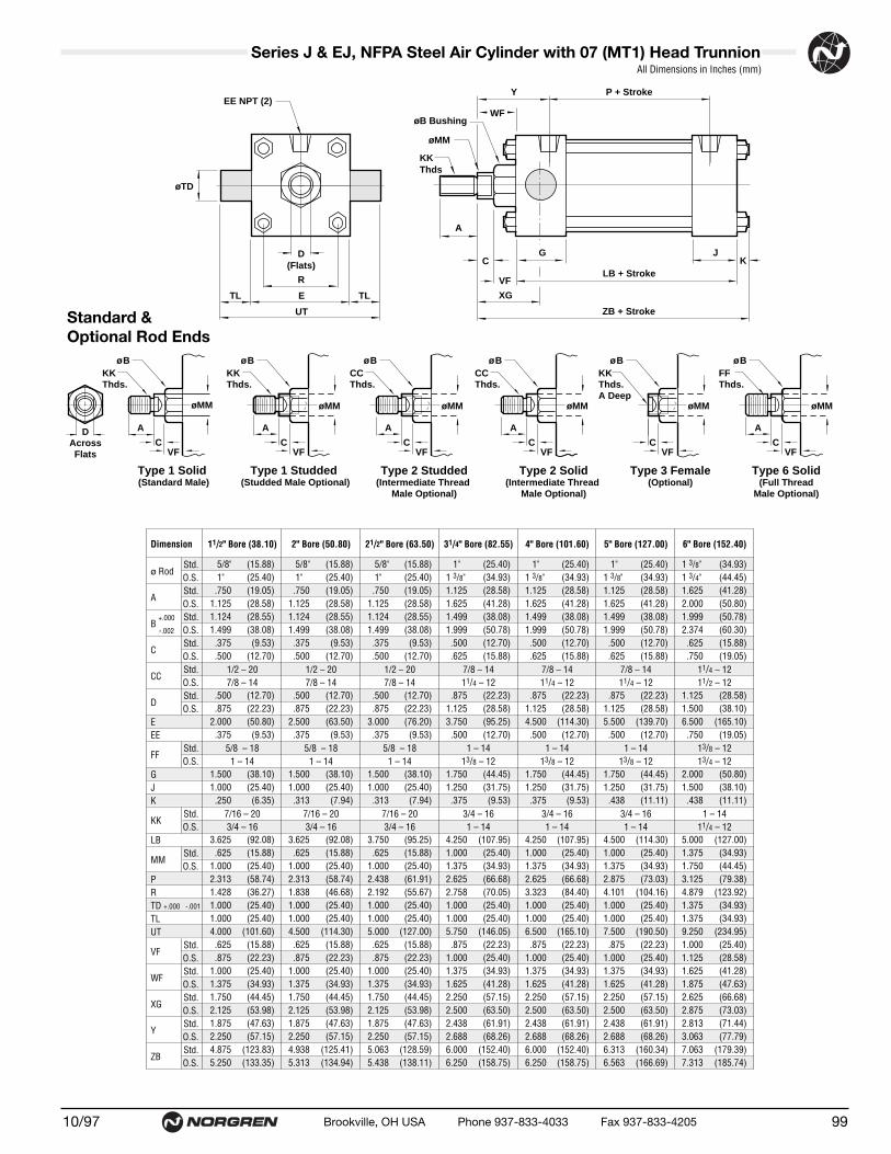
.5/8" .5/8" .5/8" .1" .1" .1" 1.3/8" 1.3/8" 1.3/8"
.1" .1" .1" 1.3/8" 1.3/8" 1.3/8" 1.3/4" 1.3/4" 1.3/4"
.750 .750 .750 1.125 1.125 1.125 1.625 1.625 1.6251.125 1.125 1.125 1.625 1.625 1.625 2.000 2.000 2.0001.124 1.124 1.124 1.499 1.499 1.499 1.999 1.999 1.9991.499 1.499 1.499 1.999 1.999 1.999 2.374 2.374 2.374.375 .375 .375 .500 .500 .500 .625 .625 .625.500 .500 .500 .625 .625 .625 .750 .750 .750
.500 .500 .500 .875 .875 .875 1.125 1.125 1.125
.875 .875 .875 1.125 1.125 1.125 1.500 1.500 1.5002.000 2.500 3.000 3.750 4.500 5.500 6.500 7.500 8.500.375 .375 .375 .500 .500 .500 .750 .750 .750
1.500 1.500 1.500 1.750 1.750 1.750 2.000 2.000 2.0001.000 1.000 1.000 1.250 1.250 1.250 1.500 1.500 1.500.250 .313 .313 .375 .375 .438 .438 .563 .563
3.625 3.625 3.750 4.250 4.250 4.500 5.000 5.125 5.125.625 .625 .625 1.000 1.000 1.000 1.375 1.375 1.375
1.000 1.000 1.000 1.375 1.375 1.375 1.750 1.750 1.7502.313 2.313 2.438 2.625 2.625 2.875 3.125 3.250 3.2501.428 1.838 2.192 2.758 3.323 4.101 4.879 5.730 6.4351.000 1.000 1.000 1.000 1.000 1.000 1.375 1.375 1.3751.000 1.000 1.000 1.000 1.000 1.000 1.375 1.375 1.3754.000 4.500 5.000 5.750 6.500 7.500 9.250 10.250 11.250.625 .625 .625 .875 .875 .875 1.000 1.000 1.000.875 .875 .875 1.000 1.000 1.000 1.125 1.125 1.125
1.000 1.000 1.000 1.375 1.375 1.375 1.625 1.625 1.6251.375 1.375 1.375 1.625 1.625 1.625 1.875 1.875 1.8751.750 1.750 1.750 2.250 2.250 2.250 2.625 2.625 2.6252.125 2.125 2.125 2.500 2.500 2.500 2.875 2.875 2.8751.875 1.875 1.875 2.438 2.438 2.438 2.813 2.813 2.8132.250 2.250 2.250 2.688 2.688 2.688 3.063 3.063 3.0634.875 4.938 5.063 6.000 6.000 6.313 7.063 7.313 7.3135.250 5.313 5.438 6.250 6.250 6.563 7.313 7.563 7.563
Dimension 11/2" Bore (38.10) 2" Bore (50.80) 21/2" Bore (63.50) 31/4" Bore (82.55) 4" Bore (101.60) 5" Bore (127.00) 6" Bore (152.40) 7" Bore (177.80) 8" Bore (
ø RodStd.O.S.
AStd.O.S.
B +.000 Std.-.002 O.S.
CStd.O.S.
CCStd. 1/2 – 20 1/2 – 20 1/2 – 20 7/8 – 14 7/8 – 14 7/8 – 14 11/4 – 12 11/4 – 12 11/4O.S. 7/8 – 14 7/8 – 14 7/8 – 14 11/4 – 12 11/4 – 12 11/4 – 12 11/2 – 12 11/2 – 12 11/2
DStd.O.S.
EEE
FFStd. 5/8 – 18 5/8 – 18 5/8 – 18 1 – 14 1 – 14 1 – 14 13/8 – 12 13/8 – 12 13/8O.S. 1 – 14 1 – 14 1 – 14 13/8 – 12 13/8 – 12 13/8 – 12 13/4 – 12 13/4 – 12 13/4
GJK
KK Std. 7/16 – 20 7/16 – 20 7/16 – 20 3/4 – 16 3/4 – 16 3/4 – 16 1 – 14 1 – 14 1 –O.S. 3/4 – 16 3/4 – 16 3/4 – 16 1 – 14 1 – 14 1 – 14 11/4 – 12 11/4 – 12 11/4
LB
MMStd.O.S.
PRTD +.000 -.001
TLUT
VFStd.O.S.
WFStd.O.S.
XGStd.O.S.
Y Std.O.S.
ZBStd.O.S.
(15.88) (15.88) (15.88) (25.40) (25.40) (25.40) (34.93) (34.93)(25.40) (25.40) (25.40) (34.93) (34.93) (34.93) (44.45) (44.45)(19.05) (19.05) (19.05) (28.58) (28.58) (28.58) (41.28) (41.28)(28.58) (28.58) (28.58) (41.28) (41.28) (41.28) (50.80) (50.80)(28.55) (28.55) (28.55) (38.08) (38.08) (38.08) (50.78) (50.78)(38.08) (38.08) (38.08) (50.78) (50.78) (50.78) (60.30) (60.30)(9.53) (9.53) (9.53) (12.70) (12.70) (12.70) (15.88) (15.88)
(12.70) (12.70) (12.70) (15.88) (15.88) (15.88) (19.05) (19.05)
(12.70) (12.70) (12.70) (22.23) (22.23) (22.23) (28.58) (28.58)(22.23) (22.23) (22.23) (28.58) (28.58) (28.58) (38.10) (38.10)(50.80) (63.50) (76.20) (95.25) (114.30) (139.70) (165.10) (190.50)(9.53) (9.53) (9.53) (12.70) (12.70) (12.70) (19.05) (19.05)
(38.10) (38.10) (38.10) (44.45) (44.45) (44.45) (50.80) (50.80)(25.40) (25.40) (25.40) (31.75) (31.75) (31.75) (38.10) (38.10)(6.35) (7.94) (7.94) (9.53) (9.53) (11.11) (11.11) (14.29)
(92.08) (92.08) (95.25) (107.95) (107.95) (114.30) (127.00) (130.18)(15.88) (15.88) (15.88) (25.40) (25.40) (25.40) (34.93) (34.93)(25.40) (25.40) (25.40) (34.93) (34.93) (34.93) (44.45) (44.45)(58.74) (58.74) (61.91) (66.68) (66.68) (73.03) (79.38) (82.55)(36.27) (46.68) (55.67) (70.05) (84.40) (104.16) (123.92) (145.54)(25.40) (25.40) (25.40) (25.40) (25.40) (25.40) (34.93) (34.93)(25.40) (25.40) (25.40) (25.40) (25.40) (25.40) (34.93) (34.93)
(101.60) (114.30) (127.00) (146.05) (165.10) (190.50) (234.95) (260.35)(15.88) (15.88) (15.88) (22.23) (22.23) (22.23) (25.40) (25.40)(22.23) (22.23) (22.23) (25.40) (25.40) (25.40) (28.58) (28.58)(25.40) (25.40) (25.40) (34.93) (34.93) (34.93) (41.28) (41.28)(34.93) (34.93) (34.93) (41.28) (41.28) (41.28) (47.63) (47.63)(44.45) (44.45) (44.45) (57.15) (57.15) (57.15) (66.68) (66.68)(53.98) (53.98) (53.98) (63.50) (63.50) (63.50) (73.03) (73.03)(47.63) (47.63) (47.63) (61.91) (61.91) (61.91) (71.44) (71.44)(57.15) (57.15) (57.15) (68.26) (68.26) (68.26) (77.79) (77.79)
(123.83) (125.41) (128.59) (152.40) (152.40) (160.34) (179.39) (185.74)(133.35) (134.94) (138.11) (158.75) (158.75) (166.69) (185.74) (192.10)
9910/97 Brookville, OH USA Phone 937-833-4033 Fax 937-833-4205
Series J & EJ, NFPA Steel Air Cylinder with 07 (MT1) Head Trunnion All Dimensions in Inches (mm)
Standard &Optional Rod Ends
CCThds.
A
ø B
øMM
A
øMM
ø BKK Thds.
KKThds.A Deep
ø B
øMM
CCThds.
A
ø B
øMM
FFThds.
ø B
øMM
Type 2 Studded(Intermediate Thread
Male Optional)
Type 3 Female(Optional)
Type 2 Solid(Intermediate Thread
Male Optional)
Type 6 Solid(Full Thread
Male Optional)
DAcrossFlats
A
øMM
ø BKK Thds.
Type 1 Studded (Studded Male Optional)
Type 1 Solid (Standard Male)
CVF
CVF
CVF
CVF
CVF
A
CVF
EE NPT (2)
D(Flats)
R
E
UT
A
C
VF
G
ZB + Stroke
LB + Stroke
JK
P + StrokeY
øB Bushing
øMM
KKThds
WF
XG
øTD
TL TL

● NFPA (MT1) 07 Head Trunnion Mount for 7" to 12" bore sizes.
● Series J Cylinders rated to 250 PSI air,400 PSI hydraulic (non-shock).
Series EJ Cylinders rated to 250 PSI air only.
● Designed for non-lube service.
● Switches available on all bore sizes.(See page 150 & 151 for ordering information.)
● Head Trunnions are removable.
Series J & EJ, NFPA Steel Air Cylinders (ø11/2" to 12")
Cylinder with 07 (MT1) Head Trunnion
10/97100 Brookville, OH USA Phone 937-833-4033 Fax 937-833-4205
See page 156 for complete instructions on how to order cylinders.
Cylinder Order Information
Additional Options – order alphabetically – More on page 155HR Case Hardened (45 Rc)L(_ _) Port Location position 1 standard: L(Head Cap)
(specify position 1 thru 4 for head and/or cap)MS Metal Rod ScraperN(_ _) Cushion Adjust Screw Location position 2 standard: N(Head
Cap) (specify position 1 thru 4 for head and/or cap)P(_)* Non-Standard Port Sizes: [specify port size for P(_H) head
only, P(_C) cap only, or P(_) both head & cap]PS Magnetic Piston – includes aluminum tube optionRS Rod Stud
Type 1 (5/8" – 13/4" øRod)Type 2 (5/8" & 1" øRod)
RX Rod Extensions (specify length of additional rod extension)SC Single Acting Spring Extend (Cap End)–See page 155SR Single Acting Spring Retract (Rod End)–See page 155SS 303 Stainless Steel (Hard Chrome Plated)ST(_C) Stop Tube (Cap End) (specify stop tube length)ST(_R) Stop Tube (Rod End) (specify stop tube length) T Special Rod Threads (specify rod thread)TX Thread Extensions (specify length of thread extension)V Viton® Seals
*11/2", 2", 21/2" bore cylinders have 3/8" NPT Standard, 1/2" NPT oversize. 31/4", 4", 5" bore cylinders have 1/2" NPT Standard, 3/4" NPT oversize.This will add 1/8" to the overall cylinder length.
Mounting Options01 Side Tapped (MS4)03 Head Rectangular Flange (MF1)03 Head Square (ME3)–7" to 12" Bores04 Cap Rectangular Flange (MF2)04 Cap Square (ME4)–7" to 12" Bores05 Basic Cylinder No Mounting (MX0)06 Both Ends (4) Tie Rods Ext. (MX1)6B Both Ends (2) Tie Rods Ext. (MX4)6C Cap Tie Rods Ext. (MX2)6R Head Tie Rods Ext. (MX3)07 Head Trunnion (MT1)08 Cap Trunnion (MT2)09 Side Lugs (MS2)10 Center Trunnion (MT4)11 Side End Angles (MS1)12 Cap Fixed Clevis (MP1)15 Side End Lugs (MS7)16 Sleeve Nut Construction (Universal)20 Head Square Flange (MF5)21 Cap Square Flange (MF6)22 Detachable Cap Clevis (MP2)32 Cap Fixed Eye (MP3)42 Detachable Cap Eye (MP4)52 Spherical Bearing
J Series J CylinderEJ Series EJ Cylinder
07 – – – –
Bore and Stroke (write out )
Piston Rod DiametersA 5/8" Standard on 11/2", 2", 21/2"
Standard on 31/4", 4", 5"B 1"
Oversized on 11/2", 2", 21/2"Standard on 6", 7", 8"
C 13/8"Oversized on 31/4", 4", 5"Standard on 10"
D 13/4"Oversized on 6", 7", 8"Standard on 12"
E 2"Oversized on 10"
F 21/2" Oversized on 10", 12"
†Standard with EJ
†Standard with EJ
1
3
4 2
Cushion in Head 3 None5† Non-Adjustable Cushion7 Adjustable Cushion (Position 2)
Cushion in Cap 3 None5† Non-Adjustable Cushion7 Adjustable Cushion (Position 2)
Piston Rod Threads Type1 Small Male (Solid)2 Intermediate Thread Male (Solid)3 Female6 Full Thread Male (Solid)7 Plain Rod End
Port and Cushion AdjustmentPositions (As viewed from rod end:Port standard position 1, CushionAdjustment standard position 2.)NOTE: A Port and a Cushion Adjustmentcannot be in the same position. Port orcushion cannot be located in position 2 or 4 on the head end.

1.3/8" 1.3/8" 1.3/4" 2."1.3/4" 1.3/4" 2." 2.1/2"1.625 1.625 2.000 2.2502.000 2.000 2.250 3.0001.999 1.999 2.374 2.6242.374 2.374 2.624 3.124.625 .625 .750 .875.750 .750 .875 1.000
1.125 1.125 1.500 1.6881.500 1.500 1.688 2.0637.500 8.500 10.625 12.750.750 .75 1.000 1.000
2.000 2.000 2.250 2.2501.500 1.500 2.000 2.000.563 .563 .688 .688
5.125 5.125 6.375 6.8751.375 1.375 1.750 2.0001.750 1.750 2.000 2.5003.250 3.250 4.125 4.6255.730 6.435 7.969 9.4061.375 1.375 1.750 1.7501.375 1.375 1.750 1.750
10.250 11.250 14.125 16.2501.000 1.000 1.125 1.1251.125 1.125 1.125 1.2501.625 1.625 1.875 2.0001.875 1.875 2.000 2.2502.625 2.625 3.000 3.1252.875 2.875 3.125 3.3752.813 2.813 3.125 3.2503.063 3.063 3.250 3.5007.313 7.313 8.938 9.5637.563 7.563 9.063 9.813
(34.93) (34.93) (44.45) (50.80)(44.45) (44.45) (50.80) (63.50)(41.28) (41.28) (50.80) (57.15)(50.80) (50.80) (57.15) (76.20)(50.78) (50.78) (60.30) (66.65)(60.30) (60.30) (66.65) (79.35)(15.88) (15.88) (19.05) (22.23)(19.05) (19.05) (22.23) (25.40)
(28.58) (28.58) (38.10) (42.86)(38.10) (38.10) (42.86) (52.39)
(190.50) (215.90) (269.88) (323.85)(19.05) (19.05) (25.40) (25.40)
(50.80) (50.80) (57.15) (57.15)(38.10) (38.10) (50.80) (50.80)(14.29) (14.29) (17.46) (17.46)
(130.18) (130.18) (161.93) (174.63)(34.93) (34.93) (44.45) (50.80)(44.45) (44.45) (50.80) (63.50)(82.55) (82.55) (104.78) (117.48)
(145.54) (163.44) (202.41) (238.92)(34.93) (34.93) (44.45) (44.45)(34.93) (34.93) (44.45) (44.45)
(260.35) (285.75) (358.78) (412.75)(25.40) (25.40) (28.58) (28.58)(28.58) (28.58) (28.58) (31.75)(41.28) (41.28) (47.63) (50.80)(47.63) (47.63) (50.80) (57.15)(66.68) (66.68) (76.20) (79.38)(73.03) (73.03) (79.38) (85.73)(71.44) (71.44) (79.38) (82.55)(77.79) (77.79) (82.55) (88.90)
(185.74) (185.74) (227.01) (242.89)(192.09) (192.09) (230.19) (249.24)
Dimension 7" Bore (177.80) 8" Bore (203.20) 10" Bore (254.00) 12" Bore (304.80)
ø RodStd.O.S.
AStd.O.S.
B +.000 Std.-.002 O.S.
CStd.O.S.
CCStd. 11/4 – 12 11/4 – 12 11/2 – 12 13/4 – 12O.S. 11/2 – 12 11/2 – 12 13/4 – 12 21/4 – 12
DStd.O.S.
EEE
FFStd. 13/8 – 12 13/8 – 12 13/4 – 12 2 – 12O.S. 13/4 – 12 13/4 – 12 2 – 12 21/2 – 12
GJK
KK Std. 1 – 14 1 – 14 11/4 – 12 11/2 – 12O.S. 11/4 – 12 11/4 – 12 11/2 – 12 17/8 – 12
LB
MMStd.O.S.
PRTD +.000 -.001
TLUT
VFStd.O.S.
WFStd.O.S.
XGStd.O.S.
Y Std.O.S.
ZBStd.O.S.
10110/97 Brookville, OH USA Phone 937-833-4033 Fax 937-833-4205
Series J & EJ, NFPA Steel Air Cylinder with 07 (MT1) Head Trunnion All Dimensions in Inches (mm)
Standard &Optional Rod Ends
CCThds.
A
ø B
øMM
A
øMM
ø BKK Thds.
KKThds.A Deep
ø B
øMM
CCThds.
A
ø B
øMM
FFThds.
ø B
øMM
Type 2 Studded(Intermediate Thread
Male Optional)
Type 3 Female(Optional)
Type 2 Solid(Intermediate Thread
Male Optional)
Type 6 Solid(Full Thread
Male Optional)
DAcrossFlats
A
øMM
ø BKK Thds.
Type 1 Studded (Studded Male Optional)
Type 1 Solid (Standard Male)
CVF
CVF
CVF
CVF
CVF
A
CVF
EE NPT (2)
D(Flats)
R
E
UT
A
C
VF
G
ZB + Stroke
LB + Stroke
JK
P + StrokeY
øB Bushing
øMM
KKThds
WF
XG
øTD
TL TL

● NFPA (MT2) 08 Cap Trunnion Mountfor 1-1/2" to 6" bore sizes.
● Series J Cylinders rated to 250 PSI air,400 PSI hydraulic (non-shock).
Series EJ Cylinders rated to 250 PSI air only.
● Designed for non-lube service.
● Switches available on all bore sizes.(See pages 150 & 151 for ordering information.)
● Cap Trunnions are removable.
Series J & EJ, NFPA Steel Air Cylinders (ø11/2" to 12")
Cylinder with 08 (MT2) Cap Trunnion
10/97102 Brookville, OH USA Phone 937-833-4033 Fax 937-833-4205
See page 156 for complete instructions on how to order cylinders.
Cylinder Order Information
Additional Options – order alphabetically – More on page 155HR Case Hardened (45 Rc)L(_ _) Port Location position 1 standard: L(Head Cap)
(specify position 1 thru 4 for head and/or cap)MS Metal Rod ScraperN(_ _) Cushion Adjust Screw Location position 2 standard: N(Head
Cap) (specify position 1 thru 4 for head and/or cap)P(_)* Non-Standard Port Sizes: [specify port size for P(_H) head
only, P(_C) cap only, or P(_) both head & cap]PS Magnetic Piston – includes aluminum tube optionRS Rod Stud
Type 1 (5/8" – 13/4" øRod)Type 2 (5/8" & 1" øRod)
RX Rod Extensions (specify length of additional rod extension)SC Single Acting Spring Extend (Cap End)–See page 155SR Single Acting Spring Retract (Rod End)–See page 155SS 303 Stainless Steel (Hard Chrome Plated)ST(_C) Stop Tube (Cap End) (specify stop tube length)ST(_R) Stop Tube (Rod End) (specify stop tube length) T Special Rod Threads (specify rod thread)TX Thread Extensions (specify length of thread extension)V Viton® Seals
*11/2", 2", 21/2" bore cylinders have 3/8" NPT Standard, 1/2" NPT oversize. 31/4", 4", 5" bore cylinders have 1/2" NPT Standard, 3/4" NPT oversize.This will add 1/8" to the overall cylinder length.
Mounting Options01 Side Tapped (MS4)03 Head Rectangular Flange (MF1)03 Head Square (ME3)–7" to 12" Bores04 Cap Rectangular Flange (MF2)04 Cap Square (ME4)–7" to 12" Bores05 Basic Cylinder No Mounting (MX0)06 Both Ends (4) Tie Rods Ext. (MX1)6B Both Ends (2) Tie Rods Ext. (MX4)6C Cap Tie Rods Ext. (MX2)6R Head Tie Rods Ext. (MX3)07 Head Trunnion (MT1)08 Cap Trunnion (MT2)09 Side Lugs (MS2)10 Center Trunnion (MT4)11 Side End Angles (MS1)12 Cap Fixed Clevis (MP1)15 Side End Lugs (MS7)16 Sleeve Nut Construction (Universal)20 Head Square Flange (MF5)21 Cap Square Flange (MF6)22 Detachable Cap Clevis (MP2)32 Cap Fixed Eye (MP3)42 Detachable Cap Eye (MP4)52 Spherical Bearing
J Series J CylinderEJ Series EJ Cylinder
08 – – – –
Bore and Stroke (write out )
Piston Rod DiametersA 5/8" Standard on 11/2", 2", 21/2"
Standard on 31/4", 4", 5"B 1"
Oversized on 11/2", 2", 21/2"Standard on 6", 7", 8"
C 13/8"Oversized on 31/4", 4", 5"Standard on 10"
D 13/4"Oversized on 6", 7", 8"Standard on 12"
E 2"Oversized on 10"
F 21/2" Oversized on 10", 12"
†Standard with EJ
†Standard with EJ
1
3
4 2
Cushion in Head 3 None5† Non-Adjustable Cushion7 Adjustable Cushion (Position 2)
Cushion in Cap 3 None5† Non-Adjustable Cushion7 Adjustable Cushion (Position 2)
Piston Rod Threads Type1 Small Male (Solid)2 Intermediate Thread Male (Solid)3 Female6 Full Thread Male (Solid)7 Plain Rod End
Port and Cushion AdjustmentPositions (As viewed from rod end:Port standard position 1, CushionAdjustment standard position 2.)NOTE: A Port and a Cushion Adjustmentcannot be in the same position. Port orcushion cannot be located in position 2 or 4 on the cap end.
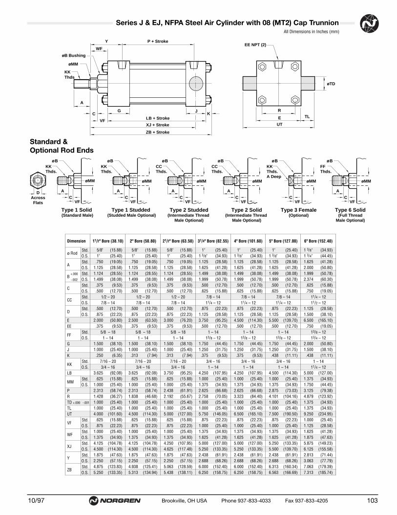
(15.88) (15.88) (15.88) (25.40) (25.40) (25.40) (34.93) (34.93)(25.40) (25.40) (25.40) (34.93) (34.93) (34.93) (44.45) (44.45)(19.05) (19.05) (19.05) (28.58) (28.58) (28.58) (41.28) (41.28)(28.58) (28.58) (28.58) (41.28) (41.28) (41.28) (50.80) (50.80)(28.55) (28.55) (28.55) (38.08) (38.08) (38.08) (50.78) (50.78)(38.08) (38.08) (38.08) (50.78) (50.78) (50.78) (60.30) (60.30)(9.53) (9.53) (9.53) (12.70) (12.70) (12.70) (15.88) (15.88)
(12.70) (12.70) (12.70) (15.88) (15.88) (15.88) (19.05) (19.05)
(12.70) (12.70) (12.70) (22.23) (22.23) (22.23) (28.58) (28.58)(22.23) (22.23) (22.23) (28.58) (28.58) (28.58) (38.10) (38.10)(50.80) (63.50) (76.20) (95.25) (114.30) (139.70) (165.10) (190.50)(9.53) (9.53) (9.53) (12.70) (12.70) (12.70) (19.05) (19.05)
(38.10) (38.10) (38.10) (44.45) (44.45) (44.45) (50.80) (50.80)(25.40) (25.40) (25.40) (31.75) (31.75) (31.75) (38.10) (38.10)(6.35) (7.94) (7.94) (9.53) (9.53) (11.11) (11.11) (14.29)
(92.08) (92.08) (95.25) (107.95) (107.95) (114.30) (127.00) (130.18)(15.88) (15.88) (15.88) (25.40) (25.40) (25.40) (34.93) (34.93)(25.40) (25.40) (25.40) (34.93) (34.93) (34.93) (44.45) (44.45)(58.74) (58.74) (61.91) (66.68) (66.68) (73.03) (79.38) (82.55)(36.27) (46.68) (55.67) (70.05) (84.40) (104.16) (123.92) (145.54)(25.40) (25.40) (25.40) (25.40) (25.40) (25.40) (34.93) (34.93)(25.40) (25.40) (25.40) (25.40) (25.40) (25.40) (34.93) (34.93)
(101.60) (114.30) (127.00) (146.05) (165.10) (190.50) (234.95) (260.35)(15.88) (15.88) (15.88) (22.23) (22.23) (22.23) (25.40) (25.40)(22.23) (22.23) (22.23) (25.40) (25.40) (25.40) (28.58) (28.58)(25.40) (25.40) (25.40) (34.93) (34.93) (34.93) (41.28) (41.28)(34.93) (34.93) (34.93) (41.28) (41.28) (41.28) (47.63) (47.63)
(104.78) (104.78) (107.95) (127.00) (127.00) (133.35) (149.23) (152.40)(114.30) (114.30) (117.48) (133.35) (133.35) (139.70) (155.58) (158.75)(47.63) (47.63) (47.63) (61.91) (61.91) (61.91) (71.44) (71.44)(57.15) (57.15) (57.15) (68.26) (68.26) (68.26) (77.79) (77.79)
(123.83) (125.41) (128.59) (152.40) (152.40) (160.34) (179.39) (185.74)(133.35) (134.94) (138.11) (158.75) (158.75) (166.69) (185.74) (192.10)
.5/8" .5/8" .5/8" .1" .1" .1" 1.3/8" 1.3/8" 1.3/8"
.1" .1" .1" 1.3/8" 1.3/8" 1.3/8" 1.3/4" 1.3/4" 1.3/4"
.750 .750 .750 1.125 1.125 1.125 1.625 1.625 1.6251.125 1.125 1.125 1.625 1.625 1.625 2.000 2.000 2.0001.124 1.124 1.124 1.499 1.499 1.499 1.999 1.999 1.9991.499 1.499 1.499 1.999 1.999 1.999 2.374 2.374 2.374.375 .375 .375 .500 .500 .500 .625 .625 .625.500 .500 .500 .625 .625 .625 .750 .750 .750
.500 .500 .500 .875 .875 .875 1.125 1.125 1.125
.875 .875 .875 1.125 1.125 1.125 1.500 1.500 1.5002.000 2.500 3.000 3.750 4.500 5.500 6.500 7.500 8.500.375 .375 .375 .500 .500 .500 .750 .750 .750
1.500 1.500 1.500 1.750 1.750 1.750 2.000 2.000 2.0001.000 1.000 1.000 1.250 1.250 1.250 1.500 1.500 1.500.250 .313 .313 .375 .375 .438 .438 .563 .563
3.625 3.625 3.750 4.250 4.250 4.500 5.000 5.125 5.125.625 .625 .625 1.000 1.000 1.000 1.375 1.375 1.375
1.000 1.000 1.000 1.375 1.375 1.375 1.750 1.750 1.7502.313 2.313 2.438 2.625 2.625 2.875 3.125 3.250 3.2501.428 1.838 2.192 2.758 3.323 4.101 4.879 5.730 6.4351.000 1.000 1.000 1.000 1.000 1.000 1.375 1.375 1.3751.000 1.000 1.000 1.000 1.000 1.000 1.375 1.375 1.3754.000 4.500 5.000 5.750 6.500 7.500 9.250 10.250 11.250.625 .625 .625 .875 .875 .875 1.000 1.000 1.000.875 .875 .875 1.000 1.000 1.000 1.125 1.125 1.125
1.000 1.000 1.000 1.375 1.375 1.375 1.625 1.625 1.6251.375 1.375 1.375 1.625 1.625 1.625 1.875 1.875 1.8754.125 4.125 4.250 5.000 5.000 5.250 5.875 6.000 6.0004.500 4.500 4.625 5.250 5.250 5.500 6.125 6.250 6.2501.875 1.875 1.875 2.438 2.438 2.438 2.813 2.813 2.8132.250 2.250 2.250 2.688 2.688 2.688 3.063 3.063 3.0634.875 4.938 5.063 6.000 6.000 6.313 7.063 7.313 7.3135.250 5.313 5.438 6.250 6.250 6.563 7.313 7.563 7.563
Dimension 11/2" Bore (38.10) 2" Bore (50.80) 21/2" Bore (63.50) 31/4" Bore (82.55) 4" Bore (101.60) 5" Bore (127.00) 6" Bore (152.40) 7" Bore (177.80) 8" Bore (
ø RodStd.O.S.
AStd.O.S.
B +.000 Std.-.002 O.S.
CStd.O.S.
CCStd. 1/2 – 20 1/2 – 20 1/2 – 20 7/8 – 14 7/8 – 14 7/8 – 14 11/4 – 12 11/4 – 12 11/4O.S. 7/8 – 14 7/8 – 14 7/8 – 14 11/4 – 12 11/4 – 12 11/4 – 12 11/2 – 12 11/2 – 12 11/2
DStd.O.S.
EEE
FFStd. 5/8 – 18 5/8 – 18 5/8 – 18 1 – 14 1 – 14 1 – 14 13/8 – 12 13/8 – 12 13/8O.S. 1 – 14 1 – 14 1 – 14 13/8 – 12 13/8 – 12 13/8 – 12 13/4 – 12 13/4 – 12 13/4
GJK
KK Std. 7/16 – 20 7/16 – 20 7/16 – 20 3/4 – 16 3/4 – 16 3/4 – 16 1 – 14 1 – 14 1 –O.S. 3/4 – 16 3/4 – 16 3/4 – 16 1 – 14 1 – 14 1 – 14 11/4 – 12 11/4 – 12 11/4
LB
MMStd.O.S.
PRTD +.000 -.001
TLUT
VFStd.O.S.
WFStd.O.S.
XJStd.O.S.
Y Std.O.S.
ZBStd.O.S.
10310/97 Brookville, OH USA Phone 937-833-4033 Fax 937-833-4205
Series J & EJ, NFPA Steel Air Cylinder with 08 (MT2) Cap Trunnion
Standard & Optional Rod Ends
All Dimensions in Inches (mm)
CCThds.
A
ø B
øMM
A
øMM
ø BKK Thds.
KKThds.A Deep
ø B
øMM
CCThds.
A
ø B
øMM
FFThds.
ø B
øMM
Type 2 Studded(Intermediate Thread
Male Optional)
Type 3 Female(Optional)
Type 2 Solid(Intermediate Thread
Male Optional)
Type 6 Solid(Full Thread
Male Optional)
DAcrossFlats
A
øMM
ø BKK Thds.
Type 1 Studded (Studded Male Optional)
Type 1 Solid (Standard Male)
CVF
CVF
CVF
CVF
CVF
A
CVF
øTD
EE NPT (2)
R
E
UT
TL
XJ + Stroke
A
C
VF
G
ZB + Stroke
LB + Stroke
JK
P + StrokeY
øB Bushing
øMM
KKThds
WF

● NFPA (MT2) 08 Cap Trunnion Mountfor 7" to 12" bore sizes.
● Series J Cylinders rated to 250 PSI air,400 PSI hydraulic (non-shock).
Series EJ Cylinders rated to 250 PSI air only.
● Designed for non-lube service.
● Switches available on all bore sizes.(See pages 150 & 151 for ordering information.)
● Cap Trunnions are removable.
Series J & EJ, NFPA Steel Air Cylinders (ø11/2" to 12")
Cylinder with 08 (MT2) Cap Trunnion
10/97104 Brookville, OH USA Phone 937-833-4033 Fax 937-833-4205
See page 156 for complete instructions on how to order cylinders.
Cylinder Order Information
Additional Options – order alphabetically – More on page 155HR Case Hardened (45 Rc)L(_ _) Port Location position 1 standard: L(Head Cap)
(specify position 1 thru 4 for head and/or cap)MS Metal Rod ScraperN(_ _) Cushion Adjust Screw Location position 2 standard: N(Head
Cap) (specify position 1 thru 4 for head and/or cap)P(_)* Non-Standard Port Sizes: [specify port size for P(_H) head
only, P(_C) cap only, or P(_) both head & cap]PS Magnetic Piston – includes aluminum tube optionRS Rod Stud
Type 1 (5/8" – 13/4" øRod)Type 2 (5/8" & 1" øRod)
RX Rod Extensions (specify length of additional rod extension)SC Single Acting Spring Extend (Cap End)–See page 155SR Single Acting Spring Retract (Rod End)–See page 155SS 303 Stainless Steel (Hard Chrome Plated)ST(_C) Stop Tube (Cap End) (specify stop tube length)ST(_R) Stop Tube (Rod End) (specify stop tube length) T Special Rod Threads (specify rod thread)TX Thread Extensions (specify length of thread extension)V Viton® Seals
*11/2", 2", 21/2" bore cylinders have 3/8" NPT Standard, 1/2" NPT oversize. 31/4", 4", 5" bore cylinders have 1/2" NPT Standard, 3/4" NPT oversize.This will add 1/8" to the overall cylinder length.
Mounting Options01 Side Tapped (MS4)03 Head Rectangular Flange (MF1)03 Head Square (ME3)–7" to 12" Bores04 Cap Rectangular Flange (MF2)04 Cap Square (ME4)–7" to 12" Bores05 Basic Cylinder No Mounting (MX0)06 Both Ends (4) Tie Rods Ext. (MX1)6B Both Ends (2) Tie Rods Ext. (MX4)6C Cap Tie Rods Ext. (MX2)6R Head Tie Rods Ext. (MX3)07 Head Trunnion (MT1)08 Cap Trunnion (MT2)09 Side Lugs (MS2)10 Center Trunnion (MT4)11 Side End Angles (MS1)12 Cap Fixed Clevis (MP1)15 Side End Lugs (MS7)16 Sleeve Nut Construction (Universal)20 Head Square Flange (MF5)21 Cap Square Flange (MF6)22 Detachable Cap Clevis (MP2)32 Cap Fixed Eye (MP3)42 Detachable Cap Eye (MP4)52 Spherical Bearing
J Series J CylinderEJ Series EJ Cylinder
08 – – – –
Bore and Stroke (write out )
Piston Rod DiametersA 5/8" Standard on 11/2", 2", 21/2"
Standard on 31/4", 4", 5"B 1"
Oversized on 11/2", 2", 21/2"Standard on 6", 7", 8"
C 13/8"Oversized on 31/4", 4", 5"Standard on 10"
D 13/4"Oversized on 6", 7", 8"Standard on 12"
E 2"Oversized on 10"
F 21/2" Oversized on 10", 12"
†Standard with EJ
†Standard with EJ
1
3
4 2
Cushion in Head 3 None5† Non-Adjustable Cushion7 Adjustable Cushion (Position 2)
Cushion in Cap 3 None5† Non-Adjustable Cushion7 Adjustable Cushion (Position 2)
Piston Rod Threads Type1 Small Male (Solid)2 Intermediate Thread Male (Solid)3 Female6 Full Thread Male (Solid)7 Plain Rod End
Port and Cushion AdjustmentPositions (As viewed from rod end:Port standard position 1, CushionAdjustment standard position 2.)NOTE: A Port and a Cushion Adjustmentcannot be in the same position. Port orcushion cannot be located in position 2 or 4 on the cap end.

(34.93) (34.93) (44.45) (50.80)(44.45) (44.45) (50.80) (63.50)(41.28) (41.28) (50.80) (57.15)(50.80) (50.80) (57.15) (76.20)(50.78) (50.78) (60.30) (66.65)(60.30) (60.30) (66.65) (79.35)(15.88) (15.88) (19.05) (22.23)(19.05) (19.05) (22.23) (25.40)
(28.58) (28.58) (38.10) (42.86)(38.10) (38.10) (42.86) (52.39)
(190.50) (215.90) (269.88) (323.85)(19.05) (19.05) (25.40) (25.40)
(50.80) (50.80) (57.15) (57.15)(38.10) (38.10) (50.80) (50.80)(14.29) (14.29) (17.46) (17.46)
(130.18) (130.18) (161.93) (174.63)(34.93) (34.93) (44.45) (50.80)(44.45) (44.45) (50.80) (63.50)(82.55) (82.55) (104.78) (117.48)
(145.54) (163.44) (202.41) (238.92)(34.93) (34.93) (44.45) (44.45)(34.93) (34.93) (44.45) (44.45)
(260.35) (285.75) (358.78) (412.75)(25.40) (25.40) (28.58) (28.58)(28.58) (28.58) (28.58) (31.75)(41.28) (41.28) (47.63) (50.80)(47.63) (47.63) (50.80) (57.15)
(152.40) (152.40) (184.15) (200.03)(158.75) (158.75) (187.33) (206.38)(71.44) (71.44) (79.38) (82.55)(77.79) (77.79) (82.55) (88.90)
(185.74) (185.74) (227.01) (242.89)(192.09) (192.09) (230.19) (249.24)
1.3/8" 1.3/8" 1.3/4" 2."1.3/4" 1.3/4" 2." 2.1/2"1.625 1.625 2.000 2.2502.000 2.000 2.250 3.0001.999 1.999 2.374 2.6242.374 2.374 2.624 3.124.625 .625 .750 .875.750 .750 .875 1.000
1.125 1.125 1.500 1.6881.500 1.500 1.688 2.0637.500 8.500 10.625 12.750.750 .750 1.000 1.000
2.000 2.000 2.250 2.2501.500 1.500 2.000 2.000.563 .563 .688 .688
5.125 5.125 6.375 6.8751.375 1.375 1.750 2.0001.750 1.750 2.000 2.5003.250 3.250 4.125 4.6255.730 6.435 7.969 9.4061.375 1.375 1.750 1.7501.375 1.375 1.750 1.750
10.250 11.250 14.125 16.2501.000 1.000 1.125 1.1251.125 1.125 1.125 1.2501.625 1.625 1.875 2.0001.875 1.875 2.000 2.2506.000 6.000 7.250 7.8756.250 6.250 7.375 8.1252.813 2.813 3.125 3.2503.063 3.063 3.250 3.5007.313 7.313 8.938 9.5637.563 7.563 9.063 9.813
Dimension 7" Bore (177.80) 8" Bore (203.20) 10" Bore (254.00) 12" Bore (304.80)
ø RodStd.O.S.
AStd.O.S.
B +.000 Std.-.002 O.S.
CStd.O.S.
CCStd. 11/4 – 12 11/4 – 12 11/2 – 12 13/4 – 12O.S. 11/2 – 12 11/2 – 12 13/4 – 12 21/4 – 12
DStd.O.S.
EEE
FFStd. 13/8 – 12 13/8 – 12 13/4 – 12 2 – 12O.S. 13/4 – 12 13/4 – 12 2 – 12 21/2 – 12
GJK
KK Std. 1 – 14 1 – 14 11/4 – 12 11/2 – 12O.S. 11/4 – 12 11/4 – 12 11/2 – 12 17/8 – 12
LB
MMStd.O.S.
PRTD +.000 -.001
TLUT
VFStd.O.S.
WFStd.O.S.
XJStd.O.S.
Y Std.O.S.
ZBStd.O.S.
10510/97 Brookville, OH USA Phone 937-833-4033 Fax 937-833-4205
Series J & EJ, NFPA Steel Air Cylinder with 08 (MT2) Cap Trunnion
Standard & Optional Rod Ends
All Dimensions in Inches (mm)
CCThds.
A
ø B
øMM
A
øMM
ø BKK Thds.
KKThds.A Deep
ø B
øMM
CCThds.
A
ø B
øMM
FFThds.
ø B
øMM
Type 2 Studded(Intermediate Thread
Male Optional)
Type 3 Female(Optional)
Type 2 Solid(Intermediate Thread
Male Optional)
Type 6 Solid(Full Thread
Male Optional)
DAcrossFlats
A
øMM
ø BKK Thds.
Type 1 Studded (Studded Male Optional)
Type 1 Solid (Standard Male)
CVF
CVF
CVF
CVF
CVF
A
CVF
øTD
EE NPT (2)
R
E
UT
TL
XJ + Stroke
A
C
VF
G
ZB + Stroke
LB + Stroke
JK
P + StrokeY
øB Bushing
øMM
KKThds
WF

● NFPA (MS2) 09 Side Lug Mountfor 1-1/2" to 6" bore sizes.
● Series J Cylinders rated to 250 PSI air,400 PSI hydraulic (non-shock).
Series EJ Cylinders rated to 250 PSI air only.
● Designed for non-lube service.
● Switches available on all bore sizes.(See pages 150 & 151 for ordering information.)
Series J & EJ, NFPA Steel Air Cylinders (ø11/2" to 12")
Cylinder with 09 (MS2) Side Lug
10/97106 Brookville, OH USA Phone 937-833-4033 Fax 937-833-4205
See page 156 for complete instructions on how to order cylinders.
Cylinder Order Information
Additional Options – order alphabetically – More on page 155HR Case Hardened (45 Rc)L(_ _) Port Location position 1 standard: L(Head Cap)
(specify position 1 thru 4 for head and/or cap)MS Metal Rod ScraperN(_ _) Cushion Adjust Screw Location position 2 standard: N(Head
Cap) (specify position 1 thru 4 for head and/or cap)P(_)* Non-Standard Port Sizes: [specify port size for P(_H) head
only, P(_C) cap only, or P(_) both head & cap]PS Magnetic Piston – includes aluminum tube optionRS Rod Stud
Type 1 (5/8" – 13/4" øRod)Type 2 (5/8" & 1" øRod)
RX Rod Extensions (specify length of additional rod extension)SC Single Acting Spring Extend (Cap End)–See page 155SR Single Acting Spring Retract (Rod End)–See page 155SS 303 Stainless Steel (Hard Chrome Plated)ST(_C) Stop Tube (Cap End) (specify stop tube length)ST(_R) Stop Tube (Rod End) (specify stop tube length) T Special Rod Threads (specify rod thread)TX Thread Extensions (specify length of thread extension)V Viton® Seals
*11/2", 2", 21/2" bore cylinders have 3/8" NPT Standard, 1/2" NPT oversize. 31/4", 4", 5" bore cylinders have 1/2" NPT Standard, 3/4" NPT oversize.This will add 1/8" to the overall cylinder length.
Mounting Options01 Side Tapped (MS4)03 Head Rectangular Flange (MF1)03 Head Square (ME3)–7" to 12" Bores04 Cap Rectangular Flange (MF2)04 Cap Square (ME4)–7" to 12" Bores05 Basic Cylinder No Mounting (MX0)06 Both Ends (4) Tie Rods Ext. (MX1)6B Both Ends (2) Tie Rods Ext. (MX4)6C Cap Tie Rods Ext. (MX2)6R Head Tie Rods Ext. (MX3)07 Head Trunnion (MT1)08 Cap Trunnion (MT2)09 Side Lugs (MS2)10 Center Trunnion (MT4)11 Side End Angles (MS1)12 Cap Fixed Clevis (MP1)15 Side End Lugs (MS7)16 Sleeve Nut Construction (Universal)20 Head Square Flange (MF5)21 Cap Square Flange (MF6)22 Detachable Cap Clevis (MP2)32 Cap Fixed Eye (MP3)42 Detachable Cap Eye (MP4)52 Spherical Bearing
J Series J CylinderEJ Series EJ Cylinder
09 – – – –
Bore and Stroke (write out )
Piston Rod DiametersA 5/8" Standard on 11/2", 2", 21/2"
Standard on 31/4", 4", 5"B 1"
Oversized on 11/2", 2", 21/2"Standard on 6", 7", 8"
C 13/8"Oversized on 31/4", 4", 5"Standard on 10"
D 13/4"Oversized on 6", 7", 8"Standard on 12"
E 2"Oversized on 10"
F 21/2" Oversized on 10", 12"
†Standard with EJ
†Standard with EJ
1
3
4 2
Cushion in Head 3 None5† Non-Adjustable Cushion7 Adjustable Cushion (Position 2)
Cushion in Cap 3 None5† Non-Adjustable Cushion7 Adjustable Cushion (Position 2)
Piston Rod Threads Type1 Small Male (Solid)2 Intermediate Thread Male (Solid)3 Female6 Full Thread Male (Solid)7 Plain Rod End
Port and Cushion AdjustmentPositions (As viewed from rod end:Port standard position 1, CushionAdjustment standard position 2.)NOTE: A Port and a Cushion Adjustmentcannot be in the same position.
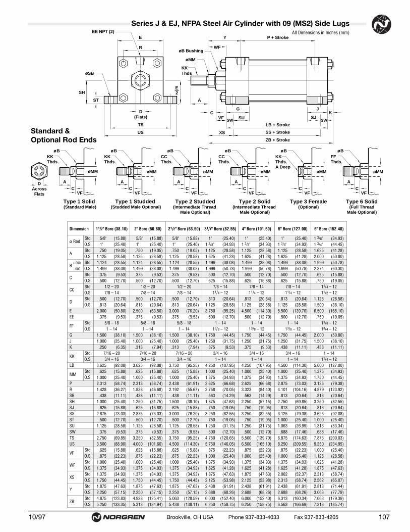
(15.88) (15.88) (15.88) (25.40) (25.40) (25.40) (34.93) (34.93)(25.40) (25.40) (25.40) (34.93) (34.93) (34.93) (44.45) (44.45)(19.05) (19.05) (19.05) (28.58) (28.58) (28.58) (41.28) (41.28)(28.58) (28.58) (28.58) (41.28) (41.28) (41.28) (50.80) (50.80)(28.55) (28.55) (28.55) (38.08) (38.08) (38.08) (50.78) (50.78)(38.08) (38.08) (38.08) (50.78) (50.78) (50.78) (60.30) (60.30)(9.53) (9.53) (9.53) (12.70) (12.70) (12.70) (15.88) (15.88)
(12.70) (12.70) (12.70) (15.88) (15.88) (15.88) (19.05) (19.05)
(12.70) (12.70) (12.70) (20.64) (20.64) (20.64) (28.58) (28.58)(20.64) (20.64) (20.64) (28.58) (28.58) (28.58) (38.10) (38.10)(50.80) (63.50) (76.20) (95.25) (114.30) (139.70) (165.10) (190.50)(9.53) (9.53) (9.53) (12.70) (12.70) (12.70) (19.05) (19.05)
(38.10) (38.10) (38.10) (44.45) (44.45) (44.45) (50.80) (50.80)(25.40) (25.40) (25.40) (31.75) (31.75) (31.75) (38.10) (38.10)(6.35) (7.94) (7.94) (9.53) (9.53) (11.11) (11.11) (14.29)
(92.08) (92.08) (95.25) (107.95) (107.95) (114.30) (127.00) (130.18)(15.88) (15.88) (15.88) (25.40) (25.40) (25.40) (34.93) (34.93)(25.40) (25.40) (25.40) (34.93) (34.93) (34.93) (44.45) (44.45)(58.74) (58.74) (61.91) (66.68) (66.68) (73.03) (79.38) (82.55)(36.27) (46.68) (55.67) (70.05) (84.40) (104.16) (123.92) (145.54)(11.11) (11.11) (11.11) (14.29) (14.29) (20.64) (20.64) (20.64)(25.40) (31.75) (38.10) (47.63) (57.15) (69.85) (82.55) (95.25)(15.88) (15.88) (15.88) (19.05) (19.05) (20.64) (20.64) (20.64)(73.03) (73.03) (76.20) (82.55) (82.55) (79.38) (92.08) (95.25)(12.70) (12.70) (12.70) (19.05) (19.05) (25.40) (25.40) (25.40)(28.58) (28.58) (28.58) (31.75) (31.75) (26.99) (33.34) (33.34)(9.53) (9.53) (9.53) (12.70) (12.70) (17.46) (17.46) (17.46)
(69.85) (82.55) (95.25) (120.65) (139.70) (174.63) (200.03) (225.43)(88.90) (101.60) (114.30) (146.05) (165.10) (209.55) (234.95) (260.35)(15.88) (15.88) (15.88) (22.23) (22.23) (22.23) (25.40) (25.40)(22.23) (22.23) (22.23) (25.40) (25.40) (25.40) (28.58) (28.58)(25.40) (25.40) (25.40) (34.93) (34.93) (34.93) (41.28) (41.28)(34.93) (34.93) (34.93) (41.28) (41.28) (41.28) (47.63) (47.63)(34.93) (34.93) (34.93) (47.63) (47.63) (52.37) (58.74) (58.74)(44.45) (44.45) (44.45) (53.98) (53.98) (58.74) (65.07) (65.07)(47.63) (47.63) (47.63) (61.91) (61.91) (61.91) (71.44) (71.44)(57.15) (57.15) (57.15) (68.26) (68.26) (68.26) (77.79) (77.79)
(123.83) (125.41) (128.59) (152.40) (152.40) (160.34) (179.39) (185.74)(133.35) (134.94) (138.11) (158.75) (158.75) (166.69) (185.74) (192.10)
Dimension 11/2" Bore (38.10) 2" Bore (50.80) 21/2" Bore (63.50) 31/4" Bore (82.55) 4" Bore (101.60) 5" Bore (127.00) 6" Bore (152.40) 7" Bore (177.80) 8" Bore (
ø RodStd.O.S.
AStd.O.S.
B +.000 Std.-.002 O.S.
CStd.O.S.
CCStd. 1/2 – 20 1/2 – 20 1/2 – 20 7/8 – 14 7/8 – 14 7/8 – 14 11/4 – 12 11/4 – 12 11/4O.S. 7/8 – 14 7/8 – 14 7/8 – 14 11/4 – 12 11/4 – 12 11/4 – 12 11/2 – 12 11/2 – 12 11/2
DStd.O.S.
EEE
FFStd. 5/8 – 18 5/8 – 18 5/8 – 18 1 – 14 1 – 14 1 – 14 13/8 – 12 13/8 – 12 13/8O.S. 1 – 14 1 – 14 1 – 14 13/8 – 12 13/8 – 12 13/8 – 12 13/4 – 12 13/4 – 12 13/4
GJK
KK Std. 7/16 – 20 7/16 – 20 7/16 – 20 3/4 – 16 3/4 – 16 3/4 – 16 1 – 14 1 – 14 1 –O.S. 3/4 – 16 3/4 – 16 3/4 – 16 1 – 14 1 – 14 1 – 14 11/4 – 12 11/4 – 12 11/4
LB
MMStd.O.S.
PR SBSHSJSSSTSUSWTSUS
VFStd.O.S.
WFStd.O.S.
XSStd.O.S.
Y Std.O.S.
ZBStd.O.S.
.5/8" .5/8" .5/8" .1" .1" .1" 1.3/8" 1.3/8" 1.3/8"
.1" .1" .1" 1.3/8" 1.3/8" 1.3/8" 1.3/4" 1.3/4" 1.3/4"
.750 .750 .750 1.125 1.125 1.125 1.625 1.625 1.6251.125 1.125 1.125 1.625 1.625 1.625 2.000 2.000 2.0001.124 1.124 1.124 1.499 1.499 1.499 1.999 1.999 1.9991.499 1.499 1.499 1.999 1.999 1.999 2.374 2.374 2.374.375 .375 .375 .500 .500 .500 .625 .625 .625.500 .500 .500 .625 .625 .625 .750 .750 .750
.500 .500 .500 .813 .813 .813 1.125 1.125 1.125
.813 .813 .813 1.125 1.125 1.125 1.500 1.500 1.5002.000 2.500 3.000 3.750 4.500 5.500 6.500 7.500 8.500.375 .375 .375 .500 .500 .500 .750 .750 .750
1.500 1.500 1.500 1.750 1.750 1.750 2.000 2.000 2.0001.000 1.000 1.000 1.250 1.250 1.250 1.500 1.500 1.500.250 .313 .313 .375 .375 .438 .438 .563 .563
3.625 3.625 3.750 4.250 4.250 4.500 5.000 5.125 5.125.625 .625 .625 1.000 1.000 1.000 1.375 1.375 1.375
1.000 1.000 1.000 1.375 1.375 1.375 1.750 1.750 1.7502.313 2.313 2.438 2.625 2.625 2.875 3.125 3.250 3.2501.428 1.838 2.192 2.758 3.323 4.101 4.879 5.730 6.442.438 .438 .438 .563 .563 .813 .813 .813 .813
1.000 1.250 1.500 1.875 2.250 2.750 3.250 3.750 4.250.625 .625 .625 .750 .750 .813 .813 .813 .813
2.875 2.875 3.000 3.250 3.250 3.125 3.625 3.750 3.750.500 .500 .500 .750 .750 1.000 1.000 1.000 1.000
1.125 1.125 1.125 1.250 1.250 1.063 1.313 1.313 1.313.375 .375 .375 .500 .500 .688 .688 .688 .688
2.750 3.250 3.750 4.750 5.500 6.875 7.875 8.875 9.8753.500 4.000 4.500 5.750 6.500 8.250 9.250 10.250 11.250.625 .625 .625 .875 .875 .875 1.000 1.000 1.000.875 .875 .875 1.000 1.000 1.000 1.125 1.125 1.125
1.000 1.000 1.000 1.375 1.375 1.375 1.625 1.625 1.6251.375 1.375 1.375 1.625 1.625 1.625 1.875 1.875 1.8751.375 1.375 1.375 1.875 1.875 2.062 2.313 2.313 2.3131.750 1.750 1.750 2.125 2.125 2.313 2.562 2.562 2.5621.875 1.875 1.875 2.438 2.438 2.438 2.813 2.813 2.8132.250 2.250 2.250 2.688 2.688 2.688 3.063 3.063 3.0634.875 4.938 5.063 6.000 6.000 6.313 7.063 7.313 7.3135.250 5.313 5.438 6.250 6.250 6.563 7.313 7.563 7.563
10710/97 Brookville, OH USA Phone 937-833-4033 Fax 937-833-4205
Series J & EJ, NFPA Steel Air Cylinder with 09 (MS2) Side LugsAll Dimensions in Inches (mm)
Standard &Optional Rod Ends
CCThds.
A
ø B
øMM
A
øMM
ø BKK Thds.
KKThds.A Deep
ø B
øMM
CCThds.
A
ø B
øMM
FFThds.
ø B
øMM
Type 2 Studded(Intermediate Thread
Male Optional)
Type 3 Female(Optional)
Type 2 Solid(Intermediate Thread
Male Optional)
Type 6 Solid(Full Thread
Male Optional)
DAcrossFlats
A
øMM
ø BKK Thds.
Type 1 Studded (Studded Male Optional)
Type 1 Solid (Standard Male)
CVF
CVF
CVF
CVF
CVF
A
CVF
A
C
XS
G
ZB + Stroke
LB + Stroke
JK
P + StrokeY
øB Bushing
øMM
KKThds
D(Flats)
TS
US
WF
SS + Stroke
SU SJSWVF
ST
SH
øSB
EE NPT (2)
R
E
E2
SW

● NFPA (MS2) 09 Side Lug Mountfor 7" to 12" bore sizes.
● Series J Cylinders rated to 250 PSI air,400 PSI hydraulic (non-shock).
Series EJ Cylinders rated to 250 PSI air only.
● Designed for non-lube service.
● Switches available on all bore sizes.(See pages 150 & 151 for ordering information.)
Series J & EJ, NFPA Steel Air Cylinders (ø11/2" to 12")
Cylinder with 09 (MS2) Side Lug
10/97108 Brookville, OH USA Phone 937-833-4033 Fax 937-833-4205
See page 156 for complete instructions on how to order cylinders.
Cylinder Order Information
Additional Options – order alphabetically – More on page 155HR Case Hardened (45 Rc)L(_ _) Port Location position 1 standard: L(Head Cap)
(specify position 1 thru 4 for head and/or cap)MS Metal Rod ScraperN(_ _) Cushion Adjust Screw Location position 2 standard: N(Head
Cap) (specify position 1 thru 4 for head and/or cap)P(_)* Non-Standard Port Sizes: [specify port size for P(_H) head
only, P(_C) cap only, or P(_) both head & cap]PS Magnetic Piston – includes aluminum tube optionRS Rod Stud
Type 1 (5/8" – 13/4" øRod)Type 2 (5/8" & 1" øRod)
RX Rod Extensions (specify length of additional rod extension)SC Single Acting Spring Extend (Cap End)–See page 155SR Single Acting Spring Retract (Rod End)–See page 155SS 303 Stainless Steel (Hard Chrome Plated)ST(_C) Stop Tube (Cap End) (specify stop tube length)ST(_R) Stop Tube (Rod End) (specify stop tube length) T Special Rod Threads (specify rod thread)TX Thread Extensions (specify length of thread extension)V Viton® Seals
*11/2", 2", 21/2" bore cylinders have 3/8" NPT Standard, 1/2" NPT oversize. 31/4", 4", 5" bore cylinders have 1/2" NPT Standard, 3/4" NPT oversize.This will add 1/8" to the overall cylinder length.
Mounting Options01 Side Tapped (MS4)03 Head Rectangular Flange (MF1)03 Head Square (ME3)–7" to 12" Bores04 Cap Rectangular Flange (MF2)04 Cap Square (ME4)–7" to 12" Bores05 Basic Cylinder No Mounting (MX0)06 Both Ends (4) Tie Rods Ext. (MX1)6B Both Ends (2) Tie Rods Ext. (MX4)6C Cap Tie Rods Ext. (MX2)6R Head Tie Rods Ext. (MX3)07 Head Trunnion (MT1)08 Cap Trunnion (MT2)09 Side Lugs (MS2)10 Center Trunnion (MT4)11 Side End Angles (MS1)12 Cap Fixed Clevis (MP1)15 Side End Lugs (MS7)16 Sleeve Nut Construction (Universal)20 Head Square Flange (MF5)21 Cap Square Flange (MF6)22 Detachable Cap Clevis (MP2)32 Cap Fixed Eye (MP3)42 Detachable Cap Eye (MP4)52 Spherical Bearing
J Series J CylinderEJ Series EJ Cylinder
09 – – – –
Bore and Stroke (write out )
Piston Rod DiametersA 5/8" Standard on 11/2", 2", 21/2"
Standard on 31/4", 4", 5"B 1"
Oversized on 11/2", 2", 21/2"Standard on 6", 7", 8"
C 13/8"Oversized on 31/4", 4", 5"Standard on 10"
D 13/4"Oversized on 6", 7", 8"Standard on 12"
E 2"Oversized on 10"
F 21/2" Oversized on 10", 12"
†Standard with EJ
†Standard with EJ
1
3
4 2
Cushion in Head 3 None5† Non-Adjustable Cushion7 Adjustable Cushion (Position 2)
Cushion in Cap 3 None5† Non-Adjustable Cushion7 Adjustable Cushion (Position 2)
Piston Rod Threads Type1 Small Male (Solid)2 Intermediate Thread Male (Solid)3 Female6 Full Thread Male (Solid)7 Plain Rod End
Port and Cushion AdjustmentPositions (As viewed from rod end:Port standard position 1, CushionAdjustment standard position 2.)NOTE: A Port and a Cushion Adjustmentcannot be in the same position.
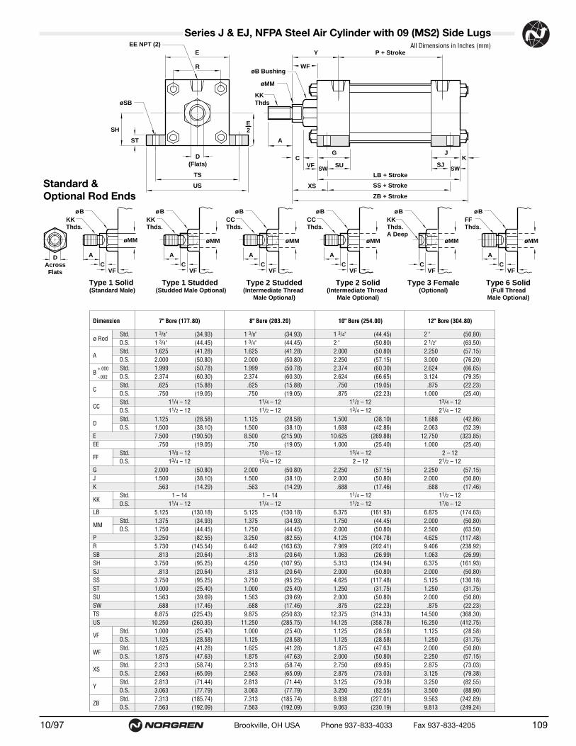
(34.93) (34.93) (44.45) (50.80)(44.45) (44.45) (50.80) (63.50)(41.28) (41.28) (50.80) (57.15)(50.80) (50.80) (57.15) (76.20)(50.78) (50.78) (60.30) (66.65)(60.30) (60.30) (66.65) (79.35)(15.88) (15.88) (19.05) (22.23)(19.05) (19.05) (22.23) (25.40)
(28.58) (28.58) (38.10) (42.86)(38.10) (38.10) (42.86) (52.39)
(190.50) (215.90) (269.88) (323.85)(19.05) (19.05) (25.40) (25.40)
(50.80) (50.80) (57.15) (57.15)(38.10) (38.10) (50.80) (50.80)(14.29) (14.29) (17.46) (17.46)
(130.18) (130.18) (161.93) (174.63)(34.93) (34.93) (44.45) (50.80)(44.45) (44.45) (50.80) (63.50)(82.55) (82.55) (104.78) (117.48)
(145.54) (163.63) (202.41) (238.92)(20.64) (20.64) (26.99) (26.99)(95.25) (107.95) (134.94) (161.93)(20.64) (20.64) (50.80) (50.80)(95.25) (95.25) (117.48) (130.18)(25.40) (25.40) (31.75) (31.75)(39.69) (39.69) (50.80) (50.80)(17.46) (17.46) (22.23) (22.23)
(225.43) (250.83) (314.33) (368.30)(260.35) (285.75) (358.78) (412.75)(25.40) (25.40) (28.58) (28.58)(28.58) (28.58) (28.58) (31.75)(41.28) (41.28) (47.63) (50.80)(47.63) (47.63) (50.80) (57.15)(58.74) (58.74) (69.85) (73.03)(65.09) (65.09) (73.03) (79.38)(71.44) (71.44) (79.38) (82.55)(77.79) (77.79) (82.55) (88.90)
(185.74) (185.74) (227.01) (242.89)(192.09) (192.09) (230.19) (249.24)
Dimension 7" Bore (177.80) 8" Bore (203.20) 10" Bore (254.00) 12" Bore (304.80)
ø RodStd.O.S.
AStd.O.S.
B +.000 Std.-.002 O.S.
CStd.O.S.
CCStd. 11/4 – 12 11/4 – 12 11/2 – 12 13/4 – 12O.S. 11/2 – 12 11/2 – 12 13/4 – 12 21/4 – 12
DStd.O.S.
EEE
FFStd. 13/8 – 12 13/8 – 12 13/4 – 12 2 – 12O.S. 13/4 – 12 13/4 – 12 2 – 12 21/2 – 12
GJK
KK Std. 1 – 14 1 – 14 11/4 – 12 11/2 – 12O.S. 11/4 – 12 11/4 – 12 11/2 – 12 17/8 – 12
LB
MMStd.O.S.
PR SBSHSJSSSTSUSWTSUS
VFStd.O.S.
WFStd.O.S.
XSStd.O.S.
Y Std.O.S.
ZBStd.O.S.
1.3/8" 1.3/8" 1.3/4" 2."1.3/4" 1.3/4" 2." 2.1/2"1.625 1.625 2.000 2.2502.000 2.000 2.250 3.0001.999 1.999 2.374 2.6242.374 2.374 2.624 3.124.625 .625 .750 .875.750 .750 .875 1.000
1.125 1.125 1.500 1.6881.500 1.500 1.688 2.0637.500 8.500 10.625 12.750.750 .750 1.000 1.000
2.000 2.000 2.250 2.2501.500 1.500 2.000 2.000.563 .563 .688 .688
5.125 5.125 6.375 6.8751.375 1.375 1.750 2.0001.750 1.750 2.000 2.5003.250 3.250 4.125 4.6255.730 6.442 7.969 9.406.813 .813 1.063 1.063
3.750 4.250 5.313 6.375.813 .813 2.000 2.000
3.750 3.750 4.625 5.1251.000 1.000 1.250 1.2501.563 1.563 2.000 2.000.688 .688 .875 .875
8.875 9.875 12.375 14.50010.250 11.250 14.125 16.2501.000 1.000 1.125 1.1251.125 1.125 1.125 1.2501.625 1.625 1.875 2.0001.875 1.875 2.000 2.2502.313 2.313 2.750 2.8752.563 2.563 2.875 3.1252.813 2.813 3.125 3.2503.063 3.063 3.250 3.5007.313 7.313 8.938 9.5637.563 7.563 9.063 9.813
10910/97 Brookville, OH USA Phone 937-833-4033 Fax 937-833-4205
Series J & EJ, NFPA Steel Air Cylinder with 09 (MS2) Side LugsAll Dimensions in Inches (mm)
Standard &Optional Rod Ends
CCThds.
A
ø B
øMM
A
øMM
ø BKK Thds.
KKThds.A Deep
ø B
øMM
CCThds.
A
ø B
øMM
FFThds.
ø B
øMM
Type 2 Studded(Intermediate Thread
Male Optional)
Type 3 Female(Optional)
Type 2 Solid(Intermediate Thread
Male Optional)
Type 6 Solid(Full Thread
Male Optional)
DAcrossFlats
A
øMM
ø BKK Thds.
Type 1 Studded (Studded Male Optional)
Type 1 Solid (Standard Male)
CVF
CVF
CVF
CVF
CVF
A
CVF
A
C
XS
G
ZB + Stroke
LB + Stroke
JK
P + StrokeY
øB Bushing
øMM
KKThds
D(Flats)
TS
US
WF
SS + Stroke
SU SJSWVF
ST
SH
øSB
EE NPT (2)
R
E
E2
SW

● NFPA(MT4) 10 Center Trunnion Mountfor 1-1/2" to 6" bore sizes.
● Series J Cylinders rated to 250 PSI air,400 PSI hydraulic (non-shock).
Series EJ Cylinders rated to 250 PSI air only.
● Designed for non-lube service.
● Switches available on all bore sizes.(See page 150 & 151 for ordering information.)
Series J & EJ, NFPA Steel Air Cylinders (ø11/2" to 12")
Cylinder with 10 (MT4) Center Trunnion
10/97110 Brookville, OH USA Phone 937-833-4033 Fax 937-833-4205
See page 156 for complete instructions on how to order cylinders.
Customer must specify XI dimension when ordering. If a rod extension isspecified, the XI (min) dimension will be increased the length of the rod extension.
Cylinder Order Information
Additional Options – order alphabetically – More on page 155HR Case Hardened (45 Rc)L(_ _) Port Location position 1 standard: L(Head Cap)
(specify position 1 thru 4 for head and/or cap)MS Metal Rod ScraperN(_ _) Cushion Adjust Screw Location position 2 standard: N(Head
Cap) (specify position 1 thru 4 for head and/or cap)P(_)* Non-Standard Port Sizes: [specify port size for P(_H) head
only, P(_C) cap only, or P(_) both head & cap]PS Magnetic Piston – includes aluminum tube optionRS Rod Stud
Type 1 (5/8" – 13/4" øRod)Type 2 (5/8" & 1" øRod)
RX Rod Extensions (specify length of additional rod extension)SC Single Acting Spring Extend (Cap End)–See page 155SR Single Acting Spring Retract (Rod End)–See page 155SS 303 Stainless Steel (Hard Chrome Plated)ST(_C) Stop Tube (Cap End) (specify stop tube length)ST(_R) Stop Tube (Rod End) (specify stop tube length) T Special Rod Threads (specify rod thread)TX Thread Extensions (specify length of thread extension)V Viton® Seals
*11/2", 2", 21/2" bore cylinders have 3/8" NPT Standard, 1/2" NPT oversize. 31/4", 4", 5" bore cylinders have 1/2" NPT Standard, 3/4" NPT oversize.This will add 1/8" to the overall cylinder length.
Mounting Options01 Side Tapped (MS4)03 Head Rectangular Flange (MF1)03 Head Square (ME3)–7" to 12" Bores04 Cap Rectangular Flange (MF2)04 Cap Square (ME4)–7" to 12" Bores05 Basic Cylinder No Mounting (MX0)06 Both Ends (4) Tie Rods Ext. (MX1)6B Both Ends (2) Tie Rods Ext. (MX4)6C Cap Tie Rods Ext. (MX2)6R Head Tie Rods Ext. (MX3)07 Head Trunnion (MT1)08 Cap Trunnion (MT2)09 Side Lugs (MS2)10 Center Trunnion (MT4)11 Side End Angles (MS1)12 Cap Fixed Clevis (MP1)15 Side End Lugs (MS7)16 Sleeve Nut Construction (Universal)20 Head Square Flange (MF5)21 Cap Square Flange (MF6)22 Detachable Cap Clevis (MP2)32 Cap Fixed Eye (MP3)42 Detachable Cap Eye (MP4)52 Spherical Bearing
J Series J CylinderEJ Series EJ Cylinder
10 – – – –
Bore and Stroke (write out )
Piston Rod DiametersA 5/8" Standard on 11/2", 2", 21/2"
Standard on 31/4", 4", 5"B 1"
Oversized on 11/2", 2", 21/2"Standard on 6", 7", 8"
C 13/8"Oversized on 31/4", 4", 5"Standard on 10"
D 13/4"Oversized on 6", 7", 8"Standard on 12"
E 2"Oversized on 10"
F 21/2" Oversized on 10", 12"
†Standard with EJ
†Standard with EJ
1
3
4 2
Cushion in Head 3 None5† Non-Adjustable Cushion7 Adjustable Cushion (Position 2)
Cushion in Cap 3 None5† Non-Adjustable Cushion7 Adjustable Cushion (Position 2)
Piston Rod Threads Type1 Small Male (Solid)2 Intermediate Thread Male (Solid)3 Female6 Full Thread Male (Solid)7 Plain Rod End
Port and Cushion AdjustmentPositions (As viewed from rod end:Port standard position 1, CushionAdjustment standard position 2.)NOTE: A Port and a Cushion Adjustmentcannot be in the same position.

(15.88) (15.88) (15.88) (25.40) (25.40) (25.40) (34.93) (34.93)(25.40) (25.40) (25.40) (34.93) (34.93) (34.93) (44.45) (44.45)(19.05) (19.05) (19.05) (28.58) (28.58) (28.58) (41.28) (41.28)(28.58) (28.58) (28.58) (41.28) (41.28) (41.28) (50.80) (50.80)(28.55) (28.55) (28.55) (38.08) (38.08) (38.08) (50.78) (50.78)(38.08) (38.08) (38.08) (50.78) (50.78) (50.78) (60.30) (60.30)(31.75) (38.10) (38.10) (50.80) (50.80) (50.80) (63.50) (63.50)(9.53) (9.53) (9.53) (12.70) (12.70) (12.70) (15.88) (15.88)
(12.70) (12.70) (12.70) (15.88) (15.88) (15.88) (19.05) (19.05)
(12.70) (12.70) (12.70) (20.64) (20.64) (20.64) (28.58) (28.58)(20.64) (20.64) (20.64) (28.58) (28.58) (28.58) (38.10) (38.10)(50.80) (63.50) (76.20) (95.25) (114.30) (139.70) (165.10) (190.50)(9.53) (9.53) (9.53) (12.70) (12.70) (12.70) (19.05) (19.05)
(38.10) (38.10) (38.10) (44.45) (44.45) (44.45) (50.80) (50.80)(25.40) (25.40) (25.40) (31.75) (31.75) (31.75) (38.10) (38.10)(6.35) (7.94) (7.94) (9.53) (9.53) (11.11) (11.11) (14.29)
(92.08) (92.08) (95.25) (107.95) (107.95) (114.30) (127.00) (130.18)(15.88) (15.88) (15.88) (25.40) (25.40) (25.40) (34.93) (34.93)(25.40) (25.40) (25.40) (34.93) (34.93) (34.93) (44.45) (44.45)(58.74) (58.74) (61.91) (66.68) (66.68) (73.03) (79.38) (82.55)(36.27) (46.68) (55.67) (70.05) (84.83) (104.16) (123.92) (145.54)(25.40) (25.40) (25.40) (25.40) (25.40) (25.40) (34.93) (34.93)(25.40) (25.40) (25.40) (25.40) (25.40) (25.40) (34.93) (34.93)(63.50) (76.20) (88.90) (114.30) (133.35) (158.75) (193.68) (222.25)
(114.30) (127.00) (139.70) (165.10) (184.15) (209.55) (263.53) (292.10)(63.50) (76.20) (88.90) (107.95) (127.00) (152.40) (177.80) (215.90)(15.88) (15.88) (15.88) (22.23) (22.23) (22.23) (25.40) (25.40)(22.23) (22.23) (22.23) (25.40) (25.40) (25.40) (28.58) (28.58)(25.40) (25.40) (25.40) (34.93) (34.93) (34.93) (41.28) (41.28)(34.93) (34.93) (34.93) (41.28) (41.28) (41.28) (47.63) (47.63)(79.38) (82.55) (82.55) (104.78) (104.78) (104.78) (117.48) (123.83)(88.90) (92.08) (92.08) (111.13) (111.13) (111.13) (123.83) (130.18)(47.63) (47.63) (47.63) (61.91) (61.91) (61.91) (71.46) (71.46)(57.15) (57.15) (57.15) (68.26) (68.26) (68.26) (77.79) (77.79)
(123.83) (125.41) (128.59) (152.40) (152.40) (160.34) (179.39) (185.74)(133.35) (134.94) (138.11) (158.75) (158.75) (166.69) (185.74) (192.10)
.5/8" .5/8" .5/8" .1" .1" .1" 1.3/8" 1.3/8" 1.3/8"
.1" .1" .1" 1.3/8" 1.3/8" 1.3/8" 1.3/4" 1.3/4" 1.3/4"
.750 .750 .750 1.125 1.125 1.125 1.625 1.625 1.6251.125 1.125 1.125 1.625 1.625 1.625 2.000 2.000 2.0001.124 1.124 1.124 1.499 1.499 1.499 1.999 1.999 1.9991.499 1.499 1.499 1.999 1.999 1.999 2.374 2.374 2.3741.250 1.500 1.500 2.000 2.000 2.000 2.500 2.500 2.500.375 .375 .375 .500 .500 .500 .625 .625 .625.500 .500 .500 .625 .625 .625 .750 .750 .750
.500 .500 .500 .813 .813 .813 1.125 1.125 1.125
.813 .813 .813 1.125 1.125 1.125 1.500 1.500 1.5002.000 2.500 3.000 3.750 4.500 5.500 6.500 7.500 8.500.375 .375 .375 .500 .500 .500 .750 .750 .750
1.500 1.500 1.500 1.750 1.750 1.750 2.000 2.000 2.0001.000 1.000 1.000 1.250 1.250 1.250 1.500 1.500 1.500.250 .313 .313 .375 .375 .438 .438 .563 .563
3.625 3.625 3.750 4.250 4.250 4.500 5.000 5.125 5.125.625 .625 .625 1.000 1.000 1.000 1.375 1.375 1.375
1.000 1.000 1.000 1.375 1.375 1.375 1.750 1.750 1.7502.313 2.313 2.438 2.625 2.625 2.875 3.125 3.250 3.2501.428 1.838 2.192 2.758 3.323 4.101 4.879 5.730 6.4351.000 1.000 1.000 1.000 1.000 1.000 1.375 1.375 1.3751.000 1.000 1.000 1.000 1.000 1.000 1.375 1.375 1.3752.500 3.000 3.500 4.500 5.250 6.250 7.625 8.750 9.7504.500 5.000 5.500 6.500 7.250 8.250 10.375 11.500 12.5002.500 3.000 3.500 4.250 5.000 6.000 7.000 8.500 9.500.625 .625 .625 .875 .875 .875 1.000 1.000 1.000.875 .875 .875 1.000 1.000 1.000 1.125 1.125 1.125
1.000 1.000 1.000 1.375 1.375 1.375 1.625 1.625 1.6251.375 1.375 1.375 1.625 1.625 1.625 1.875 1.875 1.8753.125 3.250 3.250 4.125 4.125 4.125 4.625 4.875 4.8753.500 3.625 3.625 4.375 4.375 4.375 4.875 5.125 5.1251.875 1.875 1.875 2.438 2.438 2.438 2.813 2.813 2.8132.250 2.250 2.250 2.688 2.688 2.688 3.063 3.063 3.0634.875 4.938 5.063 6.000 6.000 6.313 7.063 7.313 7.3135.250 5.313 5.438 6.250 6.250 6.563 7.313 7.563 7.563
Dimension 11/2" Bore (38.10) 2" Bore (50.80) 21/2" Bore (63.50) 31/4" Bore (82.55) 4" Bore (101.60) 5" Bore (127.00) 6" Bore (152.40) 7" Bore (177.80) 8" Bore
ø RodStd.O.S.
AStd.O.S.
B+.000 Std.-.002 O.S.
BD
CStd.O.S.
CCStd. 1/2 – 20 1/2 – 20 1/2 – 20 7/8 – 14 7/8 – 14 7/8 – 14 11/4 – 12 11/4 – 12 11/4O.S. 7/8 – 14 7/8 – 14 7/8 – 14 11/4 – 12 11/4 – 12 11/4 – 12 11/2 – 12 11/2 – 12 11/2
DStd.O.S.
EEE
FFStd. 5/8 – 18 5/8 – 18 5/8 – 18 1 – 14 1 – 14 1 – 14 13/8 – 12 13/8 – 12 13/8O.S. 1 – 14 1 – 14 1 – 14 13/8 – 12 13/8 – 12 13/8 – 12 13/4 – 12 13/4 – 12 13/4
GJK
KK Std. 7/16 – 20 7/16 – 20 7/16 – 20 3/4 – 16 3/4 – 16 3/4 – 16 1 – 14 1 – 14 1 O.S. 3/4 – 16 3/4 – 16 3/4 – 16 1 – 14 1 – 14 1 – 14 11/4 – 12 11/4 – 12 11/4
LB
MMStd.O.S.
PRTD +.000 -.001
TLTMUMUV
VFStd.O.S.
WFStd.O.S.
XI min.Std.O.S.
Y Std.O.S.
ZBStd.O.S.
EE NPT (2)
D(Flats)
UM
A
C
VF
G
ZB + Stroke
LB + Stroke
JK
P + StrokeY
øB Bushing
øMM
KKThds
WF
XI (Min.)
R
E
øTD
TL
UV
TM
BD
TL Customer Must Specify
XI
11110/97 Brookville, OH USA Phone 937-833-4033 Fax 937-833-4205
Series J & EJ, NFPA Steel Air Cylinder 10 (MT4) with Center Trunnion
Standard & Optional Rod Ends
All Dimensions in Inches (mm)
CCThds.
A
ø B
øMM
A
øMM
ø BKK Thds.
KKThds.A Deep
ø B
øMM
CCThds.
A
ø B
øMM
FFThds.
ø B
øMM
Type 2 Studded(Intermediate Thread
Male Optional)
Type 3 Female(Optional)
Type 2 Solid(Intermediate Thread
Male Optional)
Type 6 Solid(Full Thread
Male Optional)
DAcrossFlats
A
øMM
ø BKK Thds.
Type 1 Studded (Studded Male Optional)
Type 1 Solid (Standard Male)
CVF
CVF
CVF
CVF
CVF
A
CVF

● NFPA(MT4) 10 Center Trunnion Mountfor 7" to 12" bore sizes.
● Series J Cylinders rated to 250 PSI air,400 PSI hydraulic (non-shock).
Series EJ Cylinders rated to 250 PSI air only.
● Designed for non-lube service.
● Switches available on all bore sizes.(See page 150 & 151 for ordering information.)
Series J & EJ, NFPA Steel Air Cylinders (ø11/2" to 12")
Cylinder with 10 (MT4) Center Trunnion
10/97112 Brookville, OH USA Phone 937-833-4033 Fax 937-833-4205
See page 156 for complete instructions on how to order cylinders.
Customer must specify XI dimension when ordering. If a rod extension isspecified, the XI (min) dimension will be increased the length of the rod extension.
Cylinder Order Information
Additional Options – order alphabetically – More on page 155HR Case Hardened (45 Rc)L(_ _) Port Location position 1 standard: L(Head Cap)
(specify position 1 thru 4 for head and/or cap)MS Metal Rod ScraperN(_ _) Cushion Adjust Screw Location position 2 standard: N(Head
Cap) (specify position 1 thru 4 for head and/or cap)P(_)* Non-Standard Port Sizes: [specify port size for P(_H) head
only, P(_C) cap only, or P(_) both head & cap]PS Magnetic Piston – includes aluminum tube optionRS Rod Stud
Type 1 (5/8" – 13/4" øRod)Type 2 (5/8" & 1" øRod)
RX Rod Extensions (specify length of additional rod extension)SC Single Acting Spring Extend (Cap End)–See page 155SR Single Acting Spring Retract (Rod End)–See page 155SS 303 Stainless Steel (Hard Chrome Plated)ST(_C) Stop Tube (Cap End) (specify stop tube length)ST(_R) Stop Tube (Rod End) (specify stop tube length) T Special Rod Threads (specify rod thread)TX Thread Extensions (specify length of thread extension)V Viton® Seals
*11/2", 2", 21/2" bore cylinders have 3/8" NPT Standard, 1/2" NPT oversize. 31/4", 4", 5" bore cylinders have 1/2" NPT Standard, 3/4" NPT oversize.This will add 1/8" to the overall cylinder length.
Mounting Options01 Side Tapped (MS4)03 Head Rectangular Flange (MF1)03 Head Square (ME3)–7" to 12" Bores04 Cap Rectangular Flange (MF2)04 Cap Square (ME4)–7" to 12" Bores05 Basic Cylinder No Mounting (MX0)06 Both Ends (4) Tie Rods Ext. (MX1)6B Both Ends (2) Tie Rods Ext. (MX4)6C Cap Tie Rods Ext. (MX2)6R Head Tie Rods Ext. (MX3)07 Head Trunnion (MT1)08 Cap Trunnion (MT2)09 Side Lugs (MS2)10 Center Trunnion (MT4)11 Side End Angles (MS1)12 Cap Fixed Clevis (MP1)15 Side End Lugs (MS7)16 Sleeve Nut Construction (Universal)20 Head Square Flange (MF5)21 Cap Square Flange (MF6)22 Detachable Cap Clevis (MP2)32 Cap Fixed Eye (MP3)42 Detachable Cap Eye (MP4)52 Spherical Bearing
J Series J CylinderEJ Series EJ Cylinder
10 – – – –
Bore and Stroke (write out )
Piston Rod DiametersA 5/8" Standard on 11/2", 2", 21/2"
Standard on 31/4", 4", 5"B 1"
Oversized on 11/2", 2", 21/2"Standard on 6", 7", 8"
C 13/8"Oversized on 31/4", 4", 5"Standard on 10"
D 13/4"Oversized on 6", 7", 8"Standard on 12"
E 2"Oversized on 10"
F 21/2" Oversized on 10", 12"
†Standard with EJ
†Standard with EJ
1
3
4 2
Cushion in Head 3 None5† Non-Adjustable Cushion7 Adjustable Cushion (Position 2)
Cushion in Cap 3 None5† Non-Adjustable Cushion7 Adjustable Cushion (Position 2)
Piston Rod Threads Type1 Small Male (Solid)2 Intermediate Thread Male (Solid)3 Female6 Full Thread Male (Solid)7 Plain Rod End
Port and Cushion AdjustmentPositions (As viewed from rod end:Port standard position 1, CushionAdjustment standard position 2.)NOTE: A Port and a Cushion Adjustmentcannot be in the same position.

11310/97 Brookville, OH USA Phone 937-833-4033 Fax 937-833-4205
EE NPT (2)
D(Flats)
UM
A
C
VF
G
ZB + Stroke
LB + Stroke
JK
P + StrokeY
øB Bushing
øMM
KKThds
WF
XI (Min.)
R
E
øTD
TL
UV
TM
BD
TL Customer Must Specify
XI
Series J & EJ, NFPA Steel Air Cylinder 10 (MT4) with Center Trunnion
Standard & Optional Rod Ends
All Dimensions in Inches (mm)
CCThds.
A
ø B
øMM
A
øMM
ø BKK Thds.
KKThds.A Deep
ø B
øMM
CCThds.
A
ø B
øMM
FFThds.
ø B
øMM
Type 2 Studded(Intermediate Thread
Male Optional)
Type 3 Female(Optional)
Type 2 Solid(Intermediate Thread
Male Optional)
Type 6 Solid(Full Thread
Male Optional)
DAcrossFlats
A
øMM
ø BKK Thds.
Type 1 Studded (Studded Male Optional)
Type 1 Solid (Standard Male)
CVF
CVF
CVF
CVF
CVF
A
CVF
(34.93) (34.93) (44.45) (50.80)(44.45) (44.45) (50.80) (63.50)(41.28) (41.28) (50.80) (57.15)(50.80) (50.80) (57.15) (76.20)(50.78) (50.78) (60.30) (66.65)(60.30) (60.30) (66.65) (79.35)(63.50) (63.50) (76.20) (76.20)(15.88) (15.88) (19.05) (22.23)(19.05) (19.05) (22.23) (25.40)
(28.58) (28.58) (38.10) (42.86)(38.10) (38.10) (42.86) (52.39)
(190.50) (215.90) (269.88) (323.85)(19.05) (19.05) (25.40) (25.40)
(50.80) (50.80) (57.15) (57.15)(38.10) (38.10) (50.80) (50.80)(14.29) (14.29) (17.46) (17.46)
(130.18) (130.18) (161.93) (174.63)(34.93) (34.93) (44.45) (50.80)(44.45) (44.45) (50.80) (63.50)(82.55) (82.55) (104.78) (117.48)
(145.54) (163.44) (202.41) (238.92)(34.93) (34.93) (44.45) (44.45)(34.93) (34.93) (44.45) (44.45)
(222.25) (247.65) (304.80) (355.60)(292.10) (317.50) (393.70) (444.50)(215.90) ((241.30) (298.45) (349.25)(25.40) (25.40) (28.58) (28.58)(28.58) (28.58) (28.58) (31.75)(41.28) (41.28) (47.63) (50.80)(47.63) (47.63) (50.80) (57.15)
(123.83) (123.83) (142.88) (146.05)(130.18) (130.18) (146.05) (152.40)(71.46) (71.46) (79.38) (82.55)(77.79) (77.79) (82.55) (88.90)
(185.74) (185.74) (227.01) (242.89)(192.10) (192.10) (230.19) (249.24)
1.3/8" 1.3/8" 1.3/4" 2."1.3/4" 1.3/4" 2." 2.1/2"1.625 1.625 2.000 2.2502.000 2.000 2.250 3.0001.999 1.999 2.374 2.6242.374 2.374 2.624 3.1242.500 2.500 3.000 3.000.625 .625 .750 .875.750 .750 .875 1.000
1.125 1.125 1.500 1.6881.500 1.500 1.688 2.0637.500 8.500 10.625 12.750.750 .750 1.000 1.000
2.000 2.000 2.250 2.2501.500 1.500 2.000 2.000.563 .563 .688 .688
5.125 5.125 6.375 6.3751.375 1.375 1.750 2.0001.750 1.750 2.000 2.5003.250 3.250 4.125 4.6255.730 6.435 7.969 9.4061.375 1.375 1.750 1.7501.375 1.375 1.750 1.7508.750 9.750 12.000 14.000
11.500 12.500 15.500 17.5008.500 9.500 11.750 13.7501.000 1.000 1.125 1.1251.125 1.125 1.125 1.2501.625 1.625 1.875 2.0001.875 1.875 2.000 2.2504.875 4.875 5.625 5.7505.125 5.125 5.750 6.0002.813 2.813 3.125 3.2503.063 3.063 3.250 3.5007.313 7.313 8.938 9.5637.563 7.563 9.063 9.813
Dimension 7" Bore (177.80) 8" Bore (203.20) 10" Bore (254.00) 12" Bore (304.80)
ø RodStd.O.S.
AStd.O.S.
B+.000 Std.
-.002 O.S.BD
CStd.O.S.
CCStd. 11/4 – 12 11/4 – 12 11/2 – 12 13/4 – 12O.S. 11/2 – 12 11/2 – 12 13/4 – 12 21/4 – 12
DStd.O.S.
EEE
FFStd. 13/8 – 12 13/8 – 12 13/4 – 12 2 – 12O.S. 13/4 – 12 13/4 – 12 2 – 12 21/2 – 12
GJK
KK Std. 1 – 14 1 – 14 11/4 – 12 11/2 – 12O.S. 11/4 – 12 11/4 – 12 11/2 – 12 17/8 – 12
LB
MMStd.O.S.
PRTD +.000 -.001
TLTMUMUV
VFStd.O.S.
WFStd.O.S.
XI min.Std.O.S.
Y Std.O.S.
ZBStd.O.S.

● NFPA (MS1) 11 Side End Angle Mount for 1-1/2" to 6" bore sizes.
● Series J Cylinders rated to 250 PSI air,400 PSI hydraulic (non-shock).
Series EJ Cylinders rated to 250 PSI air only.
● Designed for non-lube service.
● Switches available on all bore sizes.(See page 150 & 151 for ordering information.)
Series J & EJ, NFPA Steel Air Cylinders (ø11/2" to 12")
Cylinder with 11 (MS1) Side End Angles
10/97114 Brookville, OH USA Phone 937-833-4033 Fax 937-833-4205
See page 156 for complete instructions on how to order cylinders.
Cylinder Order Information
Additional Options – order alphabetically – More on page 155HR Case Hardened (45 Rc)L(_ _) Port Location position 1 standard: L(Head Cap)
(specify position 1 thru 4 for head and/or cap)MS Metal Rod ScraperN(_ _) Cushion Adjust Screw Location position 2 standard: N(Head
Cap) (specify position 1 thru 4 for head and/or cap)P(_)* Non-Standard Port Sizes: [specify port size for P(_H) head
only, P(_C) cap only, or P(_) both head & cap]PS Magnetic Piston – includes aluminum tube optionRS Rod Stud
Type 1 (5/8" – 13/4" øRod)Type 2 (5/8" & 1" øRod)
RX Rod Extensions (specify length of additional rod extension)SC Single Acting Spring Extend (Cap End)–See page 155SR Single Acting Spring Retract (Rod End)–See page 155SS 303 Stainless Steel (Hard Chrome Plated)ST(_C) Stop Tube (Cap End) (specify stop tube length)ST(_R) Stop Tube (Rod End) (specify stop tube length) T Special Rod Threads (specify rod thread)TX Thread Extensions (specify length of thread extension)V Viton® Seals
*11/2", 2", 21/2" bore cylinders have 3/8" NPT Standard, 1/2" NPT oversize. 31/4", 4", 5" bore cylinders have 1/2" NPT Standard, 3/4" NPT oversize.This will add 1/8" to the overall cylinder length.
Mounting Options01 Side Tapped (MS4)03 Head Rectangular Flange (MF1)03 Head Square (ME3)–7" to 12" Bores04 Cap Rectangular Flange (MF2)04 Cap Square (ME4)–7" to 12" Bores05 Basic Cylinder No Mounting (MX0)06 Both Ends (4) Tie Rods Ext. (MX1)6B Both Ends (2) Tie Rods Ext. (MX4)6C Cap Tie Rods Ext. (MX2)6R Head Tie Rods Ext. (MX3)07 Head Trunnion (MT1)08 Cap Trunnion (MT2)09 Side Lugs (MS2)10 Center Trunnion (MT4)11 Side End Angles (MS1)12 Cap Fixed Clevis (MP1)15 Side End Lugs (MS7)16 Sleeve Nut Construction (Universal)20 Head Square Flange (MF5)21 Cap Square Flange (MF6)22 Detachable Cap Clevis (MP2)32 Cap Fixed Eye (MP3)42 Detachable Cap Eye (MP4)52 Spherical Bearing
J Series J CylinderEJ Series EJ Cylinder
11 – – – –
Bore and Stroke (write out )
Piston Rod DiametersA 5/8" Standard on 11/2", 2", 21/2"
Standard on 31/4", 4", 5"B 1"
Oversized on 11/2", 2", 21/2"Standard on 6", 7", 8"
C 13/8"Oversized on 31/4", 4", 5"Standard on 10"
D 13/4"Oversized on 6", 7", 8"Standard on 12"
E 2"Oversized on 10"
F 21/2" Oversized on 10", 12"
†Standard with EJ
†Standard with EJ
1
3
4 2
Cushion in Head 3 None5† Non-Adjustable Cushion7 Adjustable Cushion (Position 2)
Cushion in Cap 3 None5† Non-Adjustable Cushion7 Adjustable Cushion (Position 2)
Piston Rod Threads Type1 Small Male (Solid)2 Intermediate Thread Male (Solid)3 Female6 Full Thread Male (Solid)7 Plain Rod End
Port and Cushion AdjustmentPositions (As viewed from rod end:Port standard position 1, CushionAdjustment standard position 2.)NOTE: A Port and a Cushion Adjustmentcannot be in the same position.

.5/8" .5/8" .5/8" .1" .1" .1" 1.3/8" 1.3/8" 1.3/8"
.1" .1" .1" 1.3/8" 1.3/8" 1.3/8" 1.3/4" 1.3/4" 1.3/4"
.750 .750 .750 1.125 1.125 1.125 1.625 1.625 1.6251.125 1.125 1.125 1.625 1.625 1.625 2.000 2.000 2.000.438 .438 .438 .563 .563 .688 .813 .813 .813
1.188 1.438 1.625 1.938 2.250 2.750 3.250 3.750 4.2501.000 1.000 1.000 1.250 1.250 1.375 1.375 1.813 1.813.375 .375 .375 .500 .500 .625 .625 .688 .688.125 .125 .125 .125 .125 .187 .187 .250 .250
1.124 1.124 1.124 1.499 1.499 1.499 1.999 1.999 1.9991.499 1.499 1.499 1.999 1.999 1.999 2.374 2.374 2.374.375 .375 .375 .500 .500 .500 .625 .625 .625.500 .500 .500 .625 .625 .625 .750 .750 .750
.500 .500 .500 .813 .813 .813 1.125 1.125 1.125
.813 .813 .813 1.125 1.125 1.125 1.500 1.500 1.5002.000 2.500 3.000 3.750 4.500 5.500 6.500 7.500 8.500.375 .375 .375 .500 .500 .500 .750 .750 .750
1.500 1.500 1.500 1.750 1.750 1.750 2.000 2.000 2.0001.000 1.000 1.000 1.250 1.250 1.250 1.500 1.500 1.500.250 .313 .313 .375 .375 .438 .438 .563 .563
3.625 3.625 3.750 4.250 4.250 4.500 5.000 5.125 5.125.625 .625 .625 1.000 1.000 1.000 1.375 1.375 1.375
1.000 1.000 1.000 1.375 1.375 1.375 1.750 1.750 1.7501.375 1.375 1.375 1.875 1.875 2.000 2.125 1.813 1.8132.313 2.313 2.438 2.625 2.625 2.875 3.125 3.250 3.2501.428 1.838 2.192 2.758 3.323 4.101 4.879 5.730 6.4421.250 1.750 2.250 2.750 3.500 4.250 5.250 6.125 7.1256.000 6.000 6.125 7.375 7.375 7.875 8.500 8.750 8.750.625 .625 .625 .875 .875 .875 1.000 1.000 1.000.875 .875 .875 1.000 1.000 1.000 1.125 1.125 1.125
1.000 1.000 1.000 1.375 1.375 1.375 1.625 1.625 1.6251.375 1.375 1.375 1.625 1.625 1.625 1.875 1.875 1.8755.625 5.625 5.750 6.875 6.875 7.250 8.000 8.562 8.5626.000 6.000 6.125 7.125 7.125 7.500 8.250 8.813 8.8131.875 1.875 1.875 2.438 2.438 2.438 2.813 2.813 2.8132.250 2.250 2.250 2.688 2.688 2.688 3.063 3.063 3.063
Dimension 11/2" Bore (38.10) 2" Bore (50.80) 21/2" Bore (63.50) 31/4" Bore (82.55) 4" Bore (101.60) 5" Bore (127.00) 6" Bore (152.40) 7" Bore (177.80) 8" Bore (
ø RodStd.O.S.
AStd.O.S.
ABAHALAOAT
B +.000 Std.-.002 O.S.
CStd.O.S.
CCStd. 1/2 – 20 1/2 – 20 1/2 – 20 7/8 – 14 7/8 – 14 7/8 – 14 11/4 – 12 11/4 – 12 11/4O.S. 7/8 – 14 7/8 – 14 7/8 – 14 11/4 – 12 11/4 – 12 11/4 – 12 11/2 – 12 11/2 – 12 11/2
DStd.O.S.
EEE
FFStd. 5/8 – 18 5/8 – 18 5/8 –18 1 – 14 1 – 14 1 – 14 13/8 – 12 13/8 – 12 13/8O.S. 1 –14 1 –14 1 –14 13/8 – 12 13/8 – 12 13/8 – 12 13/4 – 12 13/4 – 12 13/4
GJK
KK Std. 7/16 – 20 7/16 – 20 7/16 – 20 3/4 – 16 3/4 – 16 3/4 – 16 1 – 14 1 – 14 1 –O.S. 3/4 – 16 3/4 – 16 3/4 – 16 1 – 14 1 – 14 1 – 14 11/4 – 12 11/4 – 12 11/4
LB
MMStd.O.S.
NFPRSSA
VF Std.O.S.
WF Std.O.S.
XAStd.O.S.
Y Std.O.S.
(15.88) (15.88) (15.88) (25.40) (25.40) (25.40) (34.93) (34.93)(25.40) (25.40) (25.40) (34.93) (34.93) (34.93) (44.45) (44.45)(19.05) (19.05) (19.05) (28.58) (28.58) (28.58) (41.28) (41.28)(28.58) (28.58) (28.58) (41.28) (41.28) (41.28) (50.80) (50.80)(11.11) (11.11) (11.11) (14.29) (14.29) (17.46) (20.64) (20.64)(30.16) (36.51) (41.28) (49.21) (57.15) (69.85) (82.55) (95.25)(25.40) (25.40) (25.40) (31.75) (31.75) (34.93) (34.93) (46.04)(9.53) (9.53) (9.53) (12.70) (12.70) (15.88) (15.88) (17.46)(3.18) (3.18) (3.18) (3.18) ((3.18) (4.75) (4.75) (6.35)
(28.55) (28.55) (28.55) (38.08) (38.08) (38.08) (50.78) (50.78)(38.08) (38.08) (38.08) (50.78) (50.78) (50.78) (60.30) (60.30)(9.53) (9.53) (9.53) (12.70) (12.70) (12.70) (15.88) (15.88)
(12.70) (12.70) (12.70) (15.88) (15.88) (15.88) (19.05) (19.05)
(12.70) (12.70) (12.70) (20.64) (20.64) (20.64) (28.58) (28.58)(20.64) (20.64) (20.64) (28.58) (28.58) (28.58) (38.10) (38.10)(50.80) (63.50) (76.20) (95.25) (114.30) (139.70) (165.10) (190.50)(9.53) (9.53) (9.53) (12.70) (12.70) (12.70) (19.05) (19.05)
(38.10) (38.10) (38.10) (44.45) (44.45) (44.45) (50.80) (50.80)(25.40) (25.40) (25.40) (31.75) (31.75) (31.75) (38.10) (38.10)(6.35) (7.94) (7.94) (9.53) (9.53) (11.11) (11.11) (14.29)
(92.08) (92.08) (95.25) (107.95) (107.95) (114.30) (127.00) (130.18)(15.88) (15.88) (15.88) (25.40) (25.40) (25.40) (34.93) (34.93)(25.40) (25.40) (25.40) (34.93) (34.93) (34.93) (44.45) (44.45)(34.93) (34.93) (34.93) (47.63) (47.63) (50.80) (53.98) (46.04)(58.74) (58.74) (61.91) (66.68) (66.68) (73.03) (79.38) (82.55)(36.27) (46.68) (55.67) (70.05) (84.40) (104.16) (123.92) (145.54)(31.75) (44.45) (57.15) (69.85) (88.90) (107.95) (133.35) (155.58)
(152.40) (152.40) (155.58) (187.33) (187.33) (200.03) (215.90) (222.25)(15.88) (15.88) (15.88) (22.23) (22.23) (22.23) (25.40) (25.40)(22.23) (22.23) (22.23) (25.40) (25.40) (25.40) (28.58) (28.58)(25.40) (25.40) (25.40) (34.93) (34.93) (34.93) (41.28) (41.28)(34.93) (34.93) (34.93) (41.28) (41.28) (41.28) (47.63) (47.63)
(142.88) (142.88) (146.05) (174.63) (174.63) (184.15) (203.20) (217.47)(152.40) (152.40) (155.58) (180.98) (180.98) (190.50) (209.55) (223.84)(47.63) (47.63) (47.63) (61.91) (61.91) (61.91) (71.44) (71.44)(57.15) (57.15) (57.15) (68.26) (68.26) (68.26) (77.79) (77.79)
11510/97 Brookville, OH USA Phone 937-833-4033 Fax 937-833-4205
Series J & EJ, NFPA Steel Air Cylinder with 11 (MS1) Side End AnglesAll Dimensions in Inches (mm)
Standard &Optional Rod Ends
CCThds.
A
ø B
øMM
A
øMM
ø BKK Thds.
KKThds.A Deep
ø B
øMM
CCThds.
A
ø B
øMM
FFThds.
ø B
øMM
Type 2 Studded(Intermediate Thread
Male Optional)
Type 3 Female(Optional)
Type 2 Solid(Intermediate Thread
Male Optional)
Type 6 Solid(Full Thread
Male Optional)
DAcrossFlats
A
øMM
ø BKK Thds.
Type 1 Studded (Studded Male Optional)
Type 1 Solid (Standard Male)
CVF
CVF
CVF
CVF
CVF
A
CVF
A
C
VF
G
SA + Stroke
LB + Stroke
J AT
P + StrokeY
øB Bushing
øMM
KKThds
D(Flats)
EE NPT (2)
R WF
S
øAB
E
AH
XA + Stroke
AOAL
K
NF

● NFPA (MS1) 11 Side End Angle Mount for 7" to 12" bore sizes.
● Series J Cylinders rated to 250 PSI air,400 PSI hydraulic (non-shock).
Series EJ Cylinders rated to 250 PSI air only.
● Designed for non-lube service.
● Switches available on all bore sizes.(See page 150 & 151 for ordering information.)
Series J & EJ, NFPA Steel Air Cylinders (ø11/2" to 12")
Cylinder with 11 (MS1) Side End Angles
10/97116 Brookville, OH USA Phone 937-833-4033 Fax 937-833-4205
See page 156 for complete instructions on how to order cylinders.
Cylinder Order Information
Additional Options – order alphabetically – More on page 155HR Case Hardened (45 Rc)L(_ _) Port Location position 1 standard: L(Head Cap)
(specify position 1 thru 4 for head and/or cap)MS Metal Rod ScraperN(_ _) Cushion Adjust Screw Location position 2 standard: N(Head
Cap) (specify position 1 thru 4 for head and/or cap)P(_)* Non-Standard Port Sizes: [specify port size for P(_H) head
only, P(_C) cap only, or P(_) both head & cap]PS Magnetic Piston – includes aluminum tube optionRS Rod Stud
Type 1 (5/8" – 13/4" øRod)Type 2 (5/8" & 1" øRod)
RX Rod Extensions (specify length of additional rod extension)SC Single Acting Spring Extend (Cap End)–See page 155SR Single Acting Spring Retract (Rod End)–See page 155SS 303 Stainless Steel (Hard Chrome Plated)ST(_C) Stop Tube (Cap End) (specify stop tube length)ST(_R) Stop Tube (Rod End) (specify stop tube length) T Special Rod Threads (specify rod thread)TX Thread Extensions (specify length of thread extension)V Viton® Seals
*11/2", 2", 21/2" bore cylinders have 3/8" NPT Standard, 1/2" NPT oversize. 31/4", 4", 5" bore cylinders have 1/2" NPT Standard, 3/4" NPT oversize.This will add 1/8" to the overall cylinder length.
Mounting Options01 Side Tapped (MS4)03 Head Rectangular Flange (MF1)03 Head Square (ME3)–7" to 12" Bores04 Cap Rectangular Flange (MF2)04 Cap Square (ME4)–7" to 12" Bores05 Basic Cylinder No Mounting (MX0)06 Both Ends (4) Tie Rods Ext. (MX1)6B Both Ends (2) Tie Rods Ext. (MX4)6C Cap Tie Rods Ext. (MX2)6R Head Tie Rods Ext. (MX3)07 Head Trunnion (MT1)08 Cap Trunnion (MT2)09 Side Lugs (MS2)10 Center Trunnion (MT4)11 Side End Angles (MS1)12 Cap Fixed Clevis (MP1)15 Side End Lugs (MS7)16 Sleeve Nut Construction (Universal)20 Head Square Flange (MF5)21 Cap Square Flange (MF6)22 Detachable Cap Clevis (MP2)32 Cap Fixed Eye (MP3)42 Detachable Cap Eye (MP4)52 Spherical Bearing
J Series J CylinderEJ Series EJ Cylinder
11 – – – –
Bore and Stroke (write out )
Piston Rod DiametersA 5/8" Standard on 11/2", 2", 21/2"
Standard on 31/4", 4", 5"B 1"
Oversized on 11/2", 2", 21/2"Standard on 6", 7", 8"
C 13/8"Oversized on 31/4", 4", 5"Standard on 10"
D 13/4"Oversized on 6", 7", 8"Standard on 12"
E 2"Oversized on 10"
F 21/2" Oversized on 10", 12"
†Standard with EJ
†Standard with EJ
1
3
4 2
Cushion in Head 3 None5† Non-Adjustable Cushion7 Adjustable Cushion (Position 2)
Cushion in Cap 3 None5† Non-Adjustable Cushion7 Adjustable Cushion (Position 2)
Piston Rod Threads Type1 Small Male (Solid)2 Intermediate Thread Male (Solid)3 Female6 Full Thread Male (Solid)7 Plain Rod End
Port and Cushion AdjustmentPositions (As viewed from rod end:Port standard position 1, CushionAdjustment standard position 2.)NOTE: A Port and a Cushion Adjustmentcannot be in the same position.

1.3/8" 1.3/8" 1.3/4" .2"1.3/4" 1.3/4" .2" 2.1/2"1.625 1.625 2.000 2.2502.000 2.000 2.250 3.000.813 .813 1.063 1.063
3.750 4.250 5.313 6.3751.813 1.813 2.125 2.125.688 .688 .875 .875.250 .250 .250 .250
1.999 1.999 2.374 2.6242.374 2.374 2.624 3.124.625 .625 .750 .875.750 .750 .875 1.000
1.125 1.125 1.500 1.6881.500 1.500 1.688 2.0637.500 8.500 10.625 12.750.750 .750 1.000 1.000
2.000 2.000 2.250 2.2501.500 1.500 2.000 2.500.563 .563 .688 .688
5.125 5.125 6.375 6.8751.375 1.375 1.750 2.0001.750 1.750 2.000 2.5001.813 1.813 1.813 1.8133.250 3.250 4.125 4.6255.730 6.442 7.969 9.4066.125 7.125 8.825 11.0008.750 8.750 10.625 11.1251.000 1.000 1.125 1.1251.125 1.125 1.125 1.2501.625 1.625 1.875 2.0001.875 1.875 2.000 2.2508.562 8.562 10.375 11.0008.813 8.813 10.500 11.2502.813 2.813 3.125 3.2503.063 3.063 3.250 3.500
(34.93) (34.93) (44.45) (50.80)(44.45) (44.45) (50.80) (63. 50)(41.28) (41.28) (50.80) (57.15)(50.80) (50.80) (57.15) (76.20)(20.64) (20.64) (26.99) (26.99)(95.25) (107.95) (134.94) (161.93)(46.04) (46.04) (53.98) (53.98)(17.46) (17.46) (22.23) (22.23)(6.35) (6.35) (6.35) (6.35)
(50.78) (50.78) (60.30) (66.65)(60.30) (60.30) (66.65) (79.35)(15.88) (15.88) (19.05) (22.23)(19.05) (19.05) (22.23) (25.40)
(28.58) (28.58) (38.10) (42.86)(38.10) (38.10) (42.86) (52.39)
(190.50) (215.90) (269.88) (323.85)(19.05) (19.05) (25.40) (25.40
(50.80) (50.80) (57.15) (57.15)(38.10) (38.10) (50.80) (50.80)(14.29) (14.29) (17.46) (17.46)
(130.18) (130.18) (161.93) (174.63)(34.93) (34.93) (44.45) (50.80)(44.45) (44.45) (50.80) (63.50)(46.04) (46.04) (46.04) (46.04)(82.55) (82.55) (104.78) (117.48)
(145.54) (163.63) (202.41) (238.92)(155.58) (180.98) (225.43) (279.40)(222.25) (222.25) (269.53) (282.58)(25.40) (25.40) (28.58) (28.58)(28.58) (28.58) (28.58) (31.75)(41.28) (41.28) (47.63) (50.80)(47.63) (47.63) (50.80) (57.15)
(217.47) (217.47) (263.53) (279.40)(223.84) (223.84) (266.70) (285.75)(71.44) (71.44) (79.38) (82.55)(77.79) (77.79) (82.55) (88.90)
Dimension 7" Bore (177.80) 8" Bore (203.20) 10" Bore (254.00) 12" Bore (304.80)
ø RodStd.O.S.
AStd.O.S.
ABAHALAOAT
B +.000 Std.-.002 O.S.
CStd.O.S.
CCStd. 11/4 – 12 11/4 – 12 11/2 – 12 13/4 – 12O.S. 11/2 – 12 11/2 – 12 13/4 – 12 21/4 – 12
DStd.O.S.
EEE
FFStd. 13/8 – 12 13/8 – 12 13/4 – 12 2 – 12O.S. 13/4 – 12 13/4 – 12 2 – 12 21/2 – 12
GJK
KK Std. 1 – 14 1 – 14 11/4 – 12 11/2 – 12O.S. 11/4 – 12 11/4 – 12 11/2 – 12 17/8 – 12
LB
MMStd.O.S.
NFPRSSA
VF Std.O.S.
WF Std.O.S.
XAStd.O.S.
Y Std.O.S.
11710/97 Brookville, OH USA Phone 937-833-4033 Fax 937-833-4205
Series J & EJ, NFPA Steel Air Cylinder with 11 (MS1) Side End AnglesAll Dimensions in Inches (mm)
Standard &Optional Rod Ends
CCThds.
A
ø B
øMM
A
øMM
ø BKK Thds.
KKThds.A Deep
ø B
øMM
CCThds.
A
ø B
øMM
FFThds.
ø B
øMM
Type 2 Studded(Intermediate Thread
Male Optional)
Type 3 Female(Optional)
Type 2 Solid(Intermediate Thread
Male Optional)
Type 6 Solid(Full Thread
Male Optional)
DAcrossFlats
A
øMM
ø BKK Thds.
Type 1 Studded (Studded Male Optional)
Type 1 Solid (Standard Male)
CVF
CVF
CVF
CVF
CVF
A
CVF
A
C
VF
G
SA + Stroke
LB + Stroke
J AT
P + StrokeY
øB Bushing
øMM
KKThds
D(Flats)
EE NPT (2)
R WF
S
øAB
E
AH
XA + Stroke
AOAL
K
NF

● NFPA (MP1) 12 Cap Fixed Clevis Mountfor 1-1/2" to 6" steel bore sizes.
● Series J Cylinders rated to 250 PSI air,400 PSI hydraulic (non-shock).
Series EJ Cylinders rated to 250 PSI air only.
● Designed for non-lube service.
● Switches available on all bore sizes.(See pages 150 & 151 for ordering information.)
Series J & EJ, NFPA Steel Air Cylinders (ø11/2" to 12")
Cylinder with 12 (MP1) Cap Fixed Clevis
10/97118 Brookville, OH USA Phone 937-833-4033 Fax 937-833-4205
See page 156 for complete instructions on how to order cylinders.
Additional Options – order alphabetically – More on page 155HR Case Hardened (45 Rc)L(_ _) Port Location position 1 standard: L(Head Cap)
(specify position 1 thru 4 for head and/or cap)MS Metal Rod ScraperN(_ _) Cushion Adjust Screw Location position 2 standard: N(Head
Cap) (specify position 1 thru 4 for head and/or cap)P(_)* Non-Standard Port Sizes: [specify port size for P(_H) head
only, P(_C) cap only, or P(_) both head & cap]PS Magnetic Piston RS Rod Stud
Type 1 (5/8" – 13/4" øRod)Type 2 (5/8" & 1" øRod)
RX Rod Extensions (specify length of additional rod extension)SC Single Acting Spring Extend (Cap End)–See page 155SR Single Acting Spring Retract (Rod End)–See page 155SS 303 Stainless Steel (Hard Chrome Plated)ST(_C) Stop Tube (Cap End) (specify stop tube length)ST(_R) Stop Tube (Rod End) (specify stop tube length) T Special Rod Threads (specify rod thread)TX Thread Extensions (specify length of thread extension)V Viton® Seals
*11/2", 2", 21/2" bore cylinders have 3/8" NPT Standard, 1/2" NPT oversize. 31/4", 4", 5" bore cylinders have 1/2" NPT Standard, 3/4" NPT oversize.This will add 1/8" to the overall cylinder length.
Mounting Options01 Side Tapped (MS4)03 Head Rectangular Flange (MF1)03 Head Square (ME3) –7" to12" Bores04 Cap Rectangular Flange (MF2)04 Cap Square (ME4) – 7" to 12" Bores05 Basic Cylinder No Mounting (MX0)06 Both Ends (4) Tie Rods Ext. (MX1)6B Both Ends (2) Tie Rods Ext. (MX4)6C Cap Tie Rods Ext. (MX2)6R Head Tie Rods Ext. (MX3)07 Head Trunnion (MT1)08 Cap Trunnion (MT2)09 Side Lugs (MS2)10 Center Trunnion (MT4)11 Side End Angles (MS1)12 Cap Fixed Clevis (MP1)15 Side End Lugs (MS7)16 Sleeve Nut Construction (Universal)20 Head Square Flange (MF5)21 Cap Square Flange (MF6)22 Detachable Cap Clevis (MP2)32 Cap Fixed Eye (MP3)42 Detachable Cap Eye (MP4)52 Spherical Bearing
J Series J CylinderEJ Series EJ Cylinder
Cylinder Order Information
12 – – – –
Bore and Stroke (write out )
†Standard with EJ
†Standard with EJ
1
3
4 2
Cushion in Head 3 None5† Non-Adjustable Cushion7 Adjustable Cushion (Position 2)
Cushion in Cap 3 None5† Non-Adjustable Cushion7 Adjustable Cushion (Position 2)
Piston Rod Threads Type1 Small Male (Solid)2 Intermediate Thread Male (Solid)3 Female6 Full Thread Male (Solid)7 Plain Rod End
Port and Cushion AdjustmentPositions (As viewed from rod end:Port standard position 1, CushionAdjustment standard position 2.)NOTE: A Port and a Cushion Adjustmentcannot be in the same position.
Piston Rod DiametersA 5/8" Standard on 11/2", 2", 21/2"
Standard on 31/4", 4", 5"B 1"
Oversized on 11/2", 2", 21/2"Standard on 6", 7", 8"
C 13/8"Oversized on 31/4", 4", 5"Standard on 10"
D 13/4"Oversized on 6", 7", 8"Standard on 12"
E 2"Oversized on 10"
F 21/2" Oversized on 10", 12"

.5/8" .5/8" .5/8" .1" .1" .1" 1.3/8" 1.3/8" 1.3/8"
.1" .1" .1" 1.3/8" 1.3/8" 1.3/8" 1.3/4" 1.3/4" 1.3/4"
.750 .750 .750 1.125 1.125 1.125 1.625 1.625 1.6251.125 1.125 1.125 1.625 1.625 1.625 2.000 2.000 2.0001.124 1.124 1.124 1.499 1.499 1.499 1.999 1.999 1.9991.499 1.499 1.499 1.999 1.999 1.999 2.374 2.374 2.374
.375 .375 .375 .500 .500 .500 .625 .625 .625
.500 .500 .500 .625 .625 .625 .750 .750 .750
.750 .750 .750 1.250 1.250 1.250 1.500 1.500 1.500
.500 .500 .500 .750 .750 .750 1.000 1.000 1.000
.500 .500 .500 .625 .625 .625 .750 .750 .750
.500 .500 .500 .813 .813 .813 1.125 1.125 1.125
.813 .813 .813 1.125 1.125 1.125 1.500 1.500 1.5002.000 2.500 3.000 3.750 4.500 5.500 6.500 7.500 8.500.375 .375 .375 .500 .500 .500 .750 .750 .750
1.500 1.500 1.500 1.750 1.750 1.750 2.000 2.000 2.0001.000 1.000 1.000 1.250 1.250 1.250 1.500 1.500 1.500.250 .313 .313 .375 .375 .438 .438 .563 .563
.750 .750 .750 1.250 1.250 1.250 1.500 1.500 1.5003.625 3.625 3.750 4.250 4.250 4.500 5.000 5.125 5.125.750 .750 .750 1.250 1.250 1.250 1.500 1.500 1.500.500 .500 .500 .750 .750 .750 1.000 1.000 1.000.625 .625 .625 1.000 1.000 1.000 1.375 1.375 1.375
1.000 1.000 1.000 1.375 1.375 1.375 1.750 1.750 1.750.625 .625 .625 .938 .938 .938 1.188 1.188 1.188
2.313 2.313 2.438 2.625 2.625 2.875 3.125 3.250 3.250.625 .625 .625 .875 .875 .875 1.000 1.000 1.000.875 .875 .875 1.000 1.000 1.000 1.125 1.125 1.125
1.000 1.000 1.000 1.375 1.375 1.375 1.625 1.625 1.6251.375 1.375 1.375 1.625 1.625 1.625 1.875 1.875 1.8755.375 5.375 5.500 6.875 6.875 7.125 8.125 8.250 8.2505.750 5.750 5.875 7.125 7.125 7.375 8.375 8.500 8.5001.875 1.875 1.875 2.438 2.438 2.438 2.813 2.813 2.8132.250 2.250 2.250 2.688 2.688 2.688 3.063 3.063 3.063
(15.88) (15.88) (15.88) (25.40) (25.40) (25.40) (34.93) (34.93)(25.40) (25.40) (25.40) (34.93) (34.93) (34.93) (44.45) (44.45)(19.05) (19.05) (19.05) (28.58) (28.58) (28.58) (41.28) (41.28)(28.58) (28.58) (28.58) (41.28) (41.28) (41.28) (50.80) (50.80)(28.55) (28.55) (28.55) (38.08) (38.08) (38.08) (50.78) (50.78)(38.08) (38.08) (38.08) (50.78) (50.78) (50.78) (60.30) (60.30)(9.53) (9.53) (9.53) (12.70) (12.70) (12.70) (15.88) (15.88)
(12.70) (12.70) (12.70) (15.88) (15.88) (15.88) (19.05) (19.05)(19.05) (19.05) (19.05) (31.75) (31.75) (31.75) (38.10) (38.10)
(12.70) (12.70) (12.70) (19.05) (19.05) (19.05) (25.40) (25.40)(12.70) (12.70) (12.70) (15.88) (15.88) (15.88) (19.05) (19.05)(12.70) (12.70) (12.70) (20.64) (20.64) (20.64) (28.58) (28.58)(20.64) (20.64) (20.64) (28.58) (28.58) (28.58) (38.10) (38.10)(50.80) (63.50) (76.20) (95.25) (114.30) (139.70) (165.10) (190.50) ((9.53) (9.53) (9.53) (12.70) (12.70) (12.70) (19.05) (19.05)
(38.10) (38.10) (38.10) (44.45) (44.45) (44.45) (50.80) (50.80)(25.40) (25.40) (25.40) (31.75) (31.75) (31.75) (38.10) (38.10)(6.35) (7.94) (7.94) (9.53) (9.53) (11.11) (11.11) (14.29)
(19.05) (19.05) (19.05) (31.75) (31.75) (31.75) (38.10) (38.10)(92.08) (92.08) (95.25) (107.95) (107.95) (114.30) (127.00) (130.18) ((19.05) (19.05) (19.05) (31.75) (31.75) (31.75) (38.10) (38.10)(12.70) (12.70) (12.70) (19.05) (19.05) (19.05) (25.40) (25.40) (15.88) (15.88) (15.88) (25.40) (25.40) (25.40) (34.93) (34.93)(25.40) (25.40) (25.40) (34.93) (34.93) (34.93) (44.45) (44.45)(15.88) (15.88) (15.88) (23.81) (23.81) (23.81) (30.16) (30.16)(58.74) (58.74) (61.91) (66.68) (66.68) (73.03) (79.38) (82.55)(15.88) (15.88) (15.88) (22.23) (22.23) (22.23) (25.40) (25.40)(22.23) (22.23) (22.23) (25.40) (25.40) (25.40) (28.58) (28.58)(25.40) (25.40) (25.40) (34.93) (34.93) (34.93) (41.28) (41.28)(34.93) (34.93) (34.93) (41.28) (41.28) (41.28) (47.63) (47.63)
(136.53) (136.53) (139.70) (174.63) (174.63) (180.98) (206.38) (209.55) ((146.05) (146.05) (149.23) (180.98) (180.98) (187.33) (212.73) (215.90) ((47.63) (47.63) (47.63) (61.91) (61.91) (61.91) (71.44) (71.44)(57.15) (57.15) (57.15) (68.26) (68.26) (68.26) (77.79) (77.79)
Dimension 11/2" Bore (38.10) 2" Bore (50.80) 21/2" Bore (63.50) 31/4" Bore (82.55) 4" Bore (101.60) 5" Bore (127.00) 6" Bore (152.40) 7" Bore (177.80) 8" Bore (
ø RodStd.O.S.
A Std.O.S.
B+.000 Std.-.002 O.S.
CStd.O.S.
CB
CCStd. 1/2 – 20 1/2 – 20 1/2 – 20 7/8 – 14 7/8 – 14 7/8 – 14 11/4 – 12 11/4 – 12 11/4 –O.S. 7/8 – 14 7/8 – 14 7/8 – 14 11/4 – 12 11/4 – 12 11/4 – 12 11/2 – 12 11/2 – 12 11/2 –
CDCW
DStd.O.S.
EEE
FFStd. 5/8 – 18 5/8 – 18 5/8 – 18 1 – 14 1 – 14 1 – 14 13/8 – 12 13/8 – 12 13/8 –O.S. 1 – 14 1 – 14 1 – 14 13/8 – 12 13/8 – 12 13/8 – 12 13/4 – 12 13/4 – 12 13/4 –
GJK
KK Std. 7/16 – 20 7/16 – 20 7/16 – 20 3/4 – 16 3/4 – 16 3/4 – 16 1 – 14 1 – 14 1 – O.S. 3/4 – 16 3/4 – 16 3/4 – 16 1 – 14 1 – 14 1 – 14 11/4 – 12 11/4 – 12 11/4 –
LLBLRM
MMStd.O.S.
MRP
VFStd.O.S.
WFStd.O.S.
XCStd.O.S.
Y Std.O.S.
11910/97 Brookville, OH USA Phone 937-833-4033 Fax 937-833-4205
Series J & EJ, NFPA Steel Air Cylinder with 12 (MP1) Cap Fixed ClevisAll Dimensions in Inches (mm)
Standard &Optional Rod Ends
CCThds.
A
ø B
øMM
A
øMM
ø BKK Thds.
KKThds.A Deep
ø B
øMM
CCThds.
A
ø B
øMM
FFThds.
ø B
øMM
Type 2 Studded(Intermediate Thread
Male Optional)
Type 3 Female(Optional)
Type 2 Solid(Intermediate Thread
Male Optional)
Type 6 Solid(Full Thread
Male Optional)
DAcrossFlats
A
øMM
ø BKK Thds.
Type 1 Studded (Studded Male Optional)
Type 1 Solid (Standard Male)
CVF
CVF
CVF
CVF
CVF
A
CVF
A
C
VF
G
XC + Stroke
LB + Stroke
JK
P + StrokeY
øB Bushing
øMM
KKThds
WF
L M
LR
øCD
MR
CB
EE NPT (2)
E
CW CW
Supplied withStandard Pin(See page 145)

● NFPA (MP1) 12 Cap Fixed Clevis Mountfor 7" to 12" steel bore sizes.
● Series J Cylinders rated to 250 PSI air,400 PSI hydraulic (non-shock).
Series EJ Cylinders rated to 250 PSI air only.
● Designed for non-lube service.
● Switches available on all bore sizes.(See pages 150 & 151 for ordering information.)
Series J & EJ, NFPA Steel Air Cylinders (ø11/2" to 12")
Cylinder with 12 (MP1) Cap Fixed Clevis
10/97120 Brookville, OH USA Phone 937-833-4033 Fax 937-833-4205
See page 156 for complete instructions on how to order cylinders.
Additional Options – order alphabetically – More on page 155HR Case Hardened (45 Rc)L(_ _) Port Location position 1 standard: L(Head Cap)
(specify position 1 thru 4 for head and/or cap)MS Metal Rod ScraperN(_ _) Cushion Adjust Screw Location position 2 standard: N(Head
Cap) (specify position 1 thru 4 for head and/or cap)P(_)* Non-Standard Port Sizes: [specify port size for P(_H) head
only, P(_C) cap only, or P(_) both head & cap]PS Magnetic Piston RS Rod Stud
Type 1 (5/8" – 13/4" øRod)Type 2 (5/8" & 1" øRod)
RX Rod Extensions (specify length of additional rod extension)SC Single Acting Spring Extend (Cap End)–See page 155SR Single Acting Spring Retract (Rod End)–See page 155SS 303 Stainless Steel (Hard Chrome Plated)ST(_C) Stop Tube (Cap End) (specify stop tube length)ST(_R) Stop Tube (Rod End) (specify stop tube length) T Special Rod Threads (specify rod thread)TX Thread Extensions (specify length of thread extension)V Viton® Seals
*11/2", 2", 21/2" bore cylinders have 3/8" NPT Standard, 1/2" NPT oversize. 31/4", 4", 5" bore cylinders have 1/2" NPT Standard, 3/4" NPT oversize.This will add 1/8" to the overall cylinder length.
Mounting Options01 Side Tapped (MS4)03 Head Rectangular Flange (MF1)03 Head Square (ME3) –7" to 12" Bores04 Cap Rectangular Flange (MF2)04 Cap Square (ME4) – 7" to 12" Bores05 Basic Cylinder No Mounting (MX0)06 Both Ends (4) Tie Rods Ext. (MX1)6B Both Ends (2) Tie Rods Ext. (MX4)6C Cap Tie Rods Ext. (MX2)6R Head Tie Rods Ext. (MX3)07 Head Trunnion (MT1)08 Cap Trunnion (MT2)09 Side Lugs (MS2)10 Center Trunnion (MT4)11 Side End Angles (MS1)12 Cap Fixed Clevis (MP1)15 Side End Lugs (MS7)16 Sleeve Nut Construction (Universal)20 Head Square Flange (MF5)21 Cap Square Flange (MF6)22 Detachable Cap Clevis (MP2)32 Cap Fixed Eye (MP3)42 Detachable Cap Eye (MP4)52 Spherical Bearing
J Series J CylinderEJ Series EJ Cylinder
Cylinder Order Information
12 – – – –
Bore and Stroke (write out )
†Standard with EJ
†Standard with EJ
1
3
4 2
Cushion in Head 3 None5† Non-Adjustable Cushion7 Adjustable Cushion (Position 2)
Cushion in Cap 3 None5† Non-Adjustable Cushion7 Adjustable Cushion (Position 2)
Piston Rod Threads Type1 Small Male (Solid)2 Intermediate Thread Male (Solid)3 Female6 Full Thread Male (Solid)7 Plain Rod End
Port and Cushion AdjustmentPositions (As viewed from rod end:Port standard position 1, CushionAdjustment standard position 2.)NOTE: A Port and a Cushion Adjustmentcannot be in the same position.
Piston Rod DiametersA 5/8" Standard on 11/2", 2", 21/2"
Standard on 31/4", 4", 5"B 1"
Oversized on 11/2", 2", 21/2"Standard on 6", 7", 8"
C 13/8"Oversized on 31/4", 4", 5"Standard on 10"
D 13/4"Oversized on 6", 7", 8"Standard on 12"
E 2"Oversized on 10"
F 21/2" Oversized on 10", 12"

(34.93) (34.93) (44.45) (50.80) ()(44.45) (44.45) (50.80) (63.50) ()(41.28) (41.28) (50.80) (57.15) ()(50.80) (50.80) (57.15) (76.20) ()(50.78) (50.78) (60.30) (66.65) ()(60.30) (60.30) (66.65) (79.35) ()(15.88) (15.88) (19.05) (22.23) ()(19.05) (19.05) (22.23) (25.40) ()(38.10) (38.10) (50.80) (63.50) ()
(25.40) (25.40) (34.93) (44.45) ()(19.05) (19.05) (25.40) (31.75) ()(28.58) (28.58) (38.10) (42.86) ()(38.10) (38.10) (42.86) (52.39) ()
(190.50) (215.90) (269.88) (323.85) ()(19.05) (19.05) (25.40) (25.40) ()
(50.80) (50.80) (57.15) (57.15) ()(38.10) (38.10) (50.80) (50.80) ()(14.29) (14.29) (17.46) (17.46) ()
(38.10) (38.10) (53.98) (57.15) ()(130.18) (130.18) (161.93) (174.63) ()(38.10) (38.10) (47.63) (53.98) ()(25.40) (25.40) (34.93) (44.45) ()(34.93) (34.93) (44.45) (50.80) ()(44.45) (44.45) (50.80) (63.50) ()(30.16) (30.16) (41.28) (53.98) ()(82.55) (82.55) (104.78) (117.48) ()(25.40) (25.40) (28.58) (28.58) ()(28.58) (28.58) (28.58) (31.75) ()(41.28) (41.28) (47.63) (50.80) ()(47.63) (47.63) (50.80) (57.15) ()
(209.55) (209.55) (263.53) (282.58) ()(215.90) (215.90) (266.70) (288.93) ()(71.44) (71.44) (79.38) (82.55) ()(77.79) (77.79) (82.55) (88.90) ()
Dimension 7" Bore (177.80) 8" Bore (203.20) 10" Bore (254.00) 12" Bore (304.80)
ø RodStd.O.S.
A Std.O.S.
B+.000 Std.
-.002 O.S.
CStd.O.S.
CB
CCStd. 11/4 – 12 11/4 – 12 11/2 – 12 13/4 – 12O.S. 11/2 – 12 11/2 – 12 13/4 – 12 21/4 – 12
CDCW
DStd.O.S.
EEE
FFStd. 13/8 – 12 13/8 – 12 13/4 – 12 2 – 12O.S. 13/4 – 12 13/4 – 12 2 – 12 21/2 – 12
GJK
KK Std. 1 – 14 1 – 14 11/4 – 12 11/2 – 12O.S. 11/4 – 12 11/4 – 12 11/2 – 12 17/8 – 12
LLBLRM
MMStd.O.S.
MRP
VFStd.O.S.
WFStd.O.S.
XCStd.O.S.
Y Std.O.S.
1.3/8" 1.3/8" 1.3/4" 2."1.3/4" 1.3/4" 2." 2.1/2"1.625 1.625 2.000 2.2502.000 2.000 2.250 3.0001.999 1.999 2.374 2.6242.374 2.374 2.624 3.124.625 .625 .750 .875.750 .750 .875 1.000
1.500 1.500 2.000 2.500
1.000 1.000 1.375 1.750.750 .750 1.000 1.250
1.125 1.125 1.500 1.6881.500 1.500 1.688 2.0637.500 8.500 10.625 12.750.750 .750 1.000 1.000
2.000 2.000 2.250 2.2501.500 1.500 2.000 2.000.563 .563 .688 .688
1.500 1.500 2.125 2.2505.125 5.125 6.375 6.8751.500 1.500 1.875 2.1251.000 1.000 1.375 1.7501.375 1.375 1.750 2.0001.750 1.750 2.000 2.5001.188 1.188 1.625 2.1253.250 3.250 4.125 4.6251.000 1.000 1.125 1.1251.125 1.125 1.125 1.2501.625 1.625 1.875 2.0001.875 1.875 2.000 2.2508.250 8.250 10.375 11.1258.500 8.500 10.500 11.3752.813 2.813 3.125 3.2503.063 3.063 3.250 3.500
12110/97 Brookville, OH USA Phone 937-833-4033 Fax 937-833-4205
Series J & EJ, NFPA Steel Air Cylinder with 12 (MP1) Cap Fixed ClevisAll Dimensions in Inches (mm)
Standard &Optional Rod Ends
CCThds.
A
ø B
øMM
A
øMM
ø BKK Thds.
KKThds.A Deep
ø B
øMM
CCThds.
A
ø B
øMM
FFThds.
ø B
øMM
Type 2 Studded(Intermediate Thread
Male Optional)
Type 3 Female(Optional)
Type 2 Solid(Intermediate Thread
Male Optional)
Type 6 Solid(Full Thread
Male Optional)
DAcrossFlats
A
øMM
ø BKK Thds.
Type 1 Studded (Studded Male Optional)
Type 1 Solid (Standard Male)
CVF
CVF
CVF
CVF
CVF
A
CVF
A
C
VF
G
XC + Stroke
LB + Stroke
JK
P + StrokeY
øB Bushing
øMM
KKThds
WF
L M
LR
øCD
MR
CB
EE NPT (2)
E
CW CW
Supplied withStandard Pin(See page 145)

● NFPA (MS7) 15 End Lug Mount for 1-1/2" to 8" bore sizes.
● Series J Cylinders rated to 250 PSI air,400 PSI hydraulic (non-shock).
Series EJ Cylinders rated to 250 PSI air only.
● Designed for non-lube service.
● Switches available on all bore sizes.(See pages 150 & 151 for ordering information.)
Series J & EJ, NFPA Steel Air Cylinders (ø11/2" to 8")
Cylinder with 15 (MS7) Side End Lugs
10/97122 Brookville, OH USA Phone 937-833-4033 Fax 937-833-4205
See page 156 for complete instructions on how to order cylinders.
Cylinder Order Information
Additional Options – order alphabetically – More on page 155HR Case Hardened (45 Rc)L(_ _) Port Location position 1 standard: L(Head Cap)
(specify position 1 thru 4 for head and/or cap)MS Metal Rod ScraperN(_ _) Cushion Adjust Screw Location position 2 standard: N(Head
Cap) (specify position 1 thru 4 for head and/or cap)P(_)* Non-Standard Port Sizes: [specify port size for P(_H) head
only, P(_C) cap only, or P(_) both head & cap]PS Magnetic Piston RS Rod Stud
Type 1 (5/8" – 13/4" øRod)Type 2 (5/8" & 1" øRod)
RX Rod Extensions (specify length of additional rod extension)SC Single Acting Spring Extend (Cap End)–See page 155SR Single Acting Spring Retract (Rod End)–See page 155SS 303 Stainless Steel (Hard Chrome Plated)ST(_C) Stop Tube (Cap End) (specify stop tube length)ST(_R) Stop Tube (Rod End) (specify stop tube length) T Special Rod Threads (specify rod thread)TX Thread Extensions (specify length of thread extension)V Viton® Seals
*11/2", 2", 21/2" bore cylinders have 3/8" NPT Standard, 1/2" NPT oversize. 31/4", 4", 5" bore cylinders have 1/2" NPT Standard, 3/4" NPT oversize.This will add 1/8" to the overall cylinder length.
Mounting Options01 Side Tapped (MS4)03 Head Rectangular Flange (MF1)03 Head Square (ME3) –7" to12" Bores04 Cap Rectangular Flange (MF2)04 Cap Square (ME4) – 7" to 12" Bores05 Basic Cylinder No Mounting (MX0)06 Both Ends (4) Tie Rods Ext. (MX1)6B Both Ends (2) Tie Rods Ext. (MX4)6C Cap Tie Rods Ext. (MX2)6R Head Tie Rods Ext. (MX3)07 Head Trunnion (MT1)08 Cap Trunnion (MT2)09 Side Lugs (MS2)10 Center Trunnion (MT4)11 Side End Angles (MS1)12 Cap Fixed Clevis (MP1)15 Side End Lugs (MS7)16 Sleeve Nut Construction (Universal)20 Head Square Flange (MF5)21 Cap Square Flange (MF6)22 Detachable Cap Clevis (MP2)32 Cap Fixed Eye (MP3)42 Detachable Cap Eye (MP4)52 Spherical Bearing
J Series J CylinderEJ Series EJ Cylinder
15 – – – –
Bore and Stroke (write out )
†Standard with EJ
†Standard with EJ
1
3
4 2
Cushion in Head 3 None5† Non-Adjustable Cushion7 Adjustable Cushion (Position 2)
Cushion in Cap 3 None5† Non-Adjustable Cushion7 Adjustable Cushion (Position 2)
Piston Rod Threads Type1 Small Male (Solid)2 Intermediate Thread Male (Solid)3 Female6 Full Thread Male (Solid)7 Plain Rod End
Port and Cushion AdjustmentPositions (As viewed from rod end:Port standard position 1, CushionAdjustment standard position 2.)NOTE: A Port and a Cushion Adjustmentcannot be in the same position.
Piston Rod DiametersA 5/8" Standard on 11/2", 2", 21/2"
Standard on 31/4", 4", 5"B 1"
Oversized on 11/2", 2", 21/2"Standard on 6", 7", 8"
C 13/8"Oversized on 31/4", 4", 5"Standard on 10"
D 13/4"Oversized on 6", 7", 8"Standard on 12"
E 2"Oversized on 10"
F 21/2" Oversized on 10", 12"

Dimension 11/2" Bore (38.10) 2" Bore (50.80) 21/2" Bore (63.50) 31/4" Bore (82.55) 4" Bore (101.60) 5" Bore (127.00) 6" Bore (152.40) 7" Bore (177.80) 8" Bore (203.20)
ø RodStd.O.S.
A Std.O.S.
B +.000 Std.-.002 O.S.
C Std.O.S.
CCStd. 1/2 – 20 1/2 – 20 1/2 – 20 7/8 – 14 7/8 – 14 7/8 – 14 11/4 – 12 11/4 – 12 11/4 – 12O.S. 7/8 – 14 7/8 – 14 7/8 – 14 11/4 – 12 11/4 – 12 11/4 – 12 11/2 – 12 11/2 – 12 11/2 – 12
D Std.O.S.
EEBEEEFELEOET
FFStd. 5/8 – 18 5/8 – 18 5/8 – 18 1 – 14 1 – 14 1 – 14 13/8 – 12 13/8 – 12 13/8 – 12O.S. 1 – 14 1 – 14 1 – 14 13/8 – 12 13/8 – 12 13/8 – 12 13/4 – 12 13/4 – 12 13/4 – 12
GJ
KK Std. 7/16 – 20 7/16 – 20 7/16 – 20 3/4 – 16 3/4 – 16 3/4 – 16 1 – 14 1 – 14 1 – 14O.S. 3/4 – 16 3/4 – 16 3/4 – 16 1 – 14 1 – 14 1 – 14 11/4 – 12 11/4 – 12 11/4 – 12
LB
MMStd.O.S.
PRSE
VFStd.O.S.
WFStd.O.S.
XEStd.O.S.
Y Std.O.S.
ZE Std.O.S.
.5/8" .5/8" .5/8" .1" .1" .1" 1.3/8" 1.3/8" 1.3/8"
.1" .1" .1" 1.3/8" 1.3/8" 1.3/8" 1.3/4" 1.3/4" 1.3/4"
.750 .750 .750 1.125 1.125 1.125 1.625 1.625 1.6251.125 1.125 1.125 1.625 1.625 1.625 2.000 2.000 2.0001.124 1.124 1.124 1.499 1.499 1.499 1.999 1.999 1.9991.499 1.499 1.499 1.999 1.999 1.999 2.374 2.374 2.374.375 .375 .375 .500 .500 .500 .625 .625 .625.500 .500 .500 .625 .625 .625 .750 .750 .750
.500 .500 .500 .813 .813 .813 1.125 1.125 1.125
.813 .813 .813 1.125 1.125 1.125 1.500 1.500 1.5002.000 2.500 3.000 3.750 4.500 5.500 6.500 7.500 8.500.313 .375 .375 .438 .438 .563 .563 .688 .688.375 .375 .375 .500 .500 .500 .750 .750 .750
1.125 1.313 1.438 1.500 1.625 1.688 1.750 1.750 1.750.750 .938 1.063 .875 1.000 1.063 1.000 1.125 1.125.250 .313 .313 .375 .375 .500 .500 .625 .625.500 .750 .750 1.000 1.250 1.500 1.500 1.750 2.063
1.500 1.500 1.500 1.750 1.750 1.750 2.000 2.000 2.0001.000 1.000 1.000 1.250 1.250 1.250 1.500 1.500 1.500
3.625 3.625 3.750 4.250 4.250 4.500 5.000 5.125 5.125.625 .625 .625 1.000 1.000 1.000 1.375 1.375 1.375
1.000 1.000 1.000 1.375 1.375 1.375 1.750 1.750 1.7502.313 2.313 2.438 2.625 2.625 2.875 3.125 3.250 3.2501.428 1.838 2.192 2.758 3.323 4.101 4.879 5.730 6.4425.500 5.875 6.250 6.625 6.875 7.250 7.750 8.000 8.000.625 .625 .625 .875 .875 .875 1.000 1.000 1.000.875 .875 .875 1.000 1.000 1.000 1.125 1.125 1.125
1.000 1.000 1.000 1.375 1.375 1.375 1.625 1.625 1.6251.375 1.375 1.375 1.625 1.625 1.625 1.875 1.875 1.8755.375 5.563 5.813 6.500 6.625 6.938 7.625 7.875 7.8755.750 5.938 6.188 6.750 6.875 7.188 7.875 8.125 8.1251.875 1.875 1.875 2.438 2.438 2.438 2.813 2.813 2.8132.250 2.250 2.250 2.688 2.688 2.688 3.063 3.063 3.0635.625 5.875 6.125 6.875 7.000 7.438 8.125 8.500 8.5006.000 6.250 6.500 7.125 7.250 7.688 8.375 8.750 8.750
(15.88) (15.88) (15.88) (25.40) (25.40) (25.40) (34.93) (34.93) (34.93)(25.40) (25.40) (25.40) (34.93) (34.93) (34.93) (44.45) (44.45) (44.45)(19.05) (19.05) (19.05) (28.58) (28.58) (28.58) (41.28) (41.28) (41.28)(28.58) (28.58) (28.58) (41.28) (41.28) (41.28) (50.80) (50.80) (50.80)(28.55) (28.55) (28.55) (38.08) (38.08) (38.08) (50.78) (50.78) (50.78)(38.08) (38.08) (38.08) (50.78) (50.78) (50.78) (60.30) (60.30) (60.30)(9.53) (9.53) (9.53) (12.70) (12.70) (12.70) (15.88) (15.88) (15.88)
(12.70) (12.70) (12.70) (15.88) (15.88) (15.88) (19.05) (19.05) (19.05)
(12.70) (12.70) (12.70) (20.64) (20.64) (20.64) (28.58) (28.58) (28.58)(20.64) (20.64) (20.64) (28.58) (28.58) (28.58) (38.10) (38.10) (38.10)(50.80) (63.50) (76.20) (95.25) (114.30) (139.70) (165.10) (190.50) (215.90)(7.94) (9.53) (9.53) (11.11) (11.11) (14.29) (14.29) (17.46) (17.46)(9.53) (9.53) (9.53) (12.70) (12.70) (12.70) (19.05) (19.05) (19.05)
(28.58) (33.34) (36.51) (38.10) (41.28) (42.88) (44.45) (44.45) (44.45)(19.05) (23.81) (26.99) (22.23) (25.40) (26.99) (25.40) (28.58) (28.58)(6.35) (7.94) (7.94) (9.53) (9.53) (12.70) (12.70) (15.88) (15.88)
(12.70) (19.05) (19.05) (25.40) (31.75) (38.10) (38.10) (44.45) (52.39)
(38.10) (38.10) (38.10) (44.45) (44.45) (44.45) (50.80) (50.80) (50.80)(25.40) (25.40) (25.40) (31.75) (31.75) (31.75) (38.10) (38.10) (38.10)
(92.08) (92.08) (95.25) (107.95) (107.95) (114.30) (127.00) (130.18) (130.18)(15.88) (15.88) (15.88) (25.40) (25.40) (25.40) (34.93) (34.93) (34.93)(25.40) (25.40) (25.40) (34.93) (34.93) (34.93) (44.45) (44.45) (44.45)(58.74) (58.74) (61.91) (66.68) (66.68) (73.03) (79.38) (82.55) (82.55(36.27) (46.68) (55.67) (70.05) (84.40) (104.16) (123.92) (145.54) (163.63)
(139.70) (149.23) (158.75) (168.28) (174.63) (184.15) (196.85) (203.20) (203.20)(15.88) (15.88) (15.88) (22.23) (22.23) (22.23) (25.40) (25.40) (25.40)(22.23) (22.23) (22.23) (25.40) (25.40) (25.40) (28.58) (28.58) (28.58)(25.40) (25.40) (25.40) (34.93) (34.93) (34.93) (41.28) (41.28) (41.28)(34.93) (34.93) (34.93) (41.28) (41.28) (41.28) (47.63) (47.63) (47.63)
(136.53) (141.29) (147.64) (165.10) (168.28) (176.21) (193.68) (200.03) (200.03)(146.05) (150.81) (157.16) (171.45) (174.63) (182.56) (200.03) (206.38) (206.38)(47.63) (47.63) (47.63) (61.91) (61.91) (61.91) (61.91) (71.44) (71.44)(57.15) (57.15) (57.15) (68.26) (68.26) (68.26) (77.79) (77.79) (77.79)
(142.88) (149.23) (155.58) (174.63) (177.80) (188.91) (206.38) (215.90) (215.90)(152.40) (158.75) (165.10) (180.98) (184.15) (195.26) (212.73) (222.25) (222.25)
12310/97 Brookville, OH USA Phone 937-833-4033 Fax 937-833-4205
Series J & EJ, NFPA Steel Air Cylinder with 15 (MS7) Side End LugsAll Dimensions in Inches (mm)
Standard & Optional Rod Ends
CCThds.
A
ø B
øMM
A
øMM
ø BKK Thds.
KKThds.A Deep
ø B
øMM
CCThds.
A
ø B
øMM
FFThds.
ø B
øMM
Type 2 Studded(Intermediate Thread
Male Optional)
Type 3 Female(Optional)
Type 2 Solid(Intermediate Thread
Male Optional)
Type 6 Solid(Full Thread
Male Optional)
DAcrossFlats
A
øMM
ø BKK Thds.
Type 1 Studded (Studded Male Optional)
Type 1 Solid (Standard Male)
CVF
CVF
CVF
CVF
CVF
A
CVF
C EOG
ZE + Stroke
LB + Stroke
J
P + StrokeY
øB Bushing
øMM
KKThds
D(Flats)
EE NPT (2)
WF
øEB Hole (4)
ET
XE + Stroke
VF
EL
SE + Stroke
R
E
EF
E2

Series J & EJ, NFPA Steel Air Cylinders (ø11/2" to 6")
Cylinder 16 Sleeve Nut Construction Side Tapped (Universal)
10/97124 Brookville, OH USA Phone 937-833-4033 Fax 937-833-4205
See page 156 for complete instructions on how to order cylinders.
● 16 Sleeve Nut Constuction Side Tapped (Universal Mount)for 1-1/2" to 6" bore sizes.
● Series J Cylinders rated to 250 PSI air,400 PSI hydraulic (non-shock).
Series EJ Cylinders rated to 250 PSI air only.
● Designed for non-lube service.
● Switches available on all bore sizes.(See pages 150 & 151 for ordering information.)
Cylinder Order Information
Additional Options – order alphabetically – More on page 155HR Case Hardened (45 Rc)L(_ _) Port Location position 1 standard: L(Head Cap)
(specify position 1 thru 4 for head and/or cap)MS Metal Rod ScraperN(_ _) Cushion Adjust Screw Location position 2 standard: N(Head
Cap) (specify position 1 thru 4 for head and/or cap)P(_)* Non-Standard Port Sizes: [specify port size for P(_H) head
only, P(_C) cap only, or P(_) both head & cap]PS Magnetic Piston RS Rod Stud
Type 1 (5/8" – 13/4" øRod)Type 2 (5/8" & 1" øRod)
RX Rod Extensions (specify length of additional rod extension)SC Single Acting Spring Extend (Cap End)–See page 155SR Single Acting Spring Retract (Rod End)–See page 155SS 303 Stainless Steel (Hard Chrome Plated)ST(_C) Stop Tube (Cap End) (specify stop tube length)ST(_R) Stop Tube (Rod End) (specify stop tube length) T Special Rod Threads (specify rod thread)TX Thread Extensions (specify length of thread extension)V Viton® Seals
*11/2", 2", 21/2" bore cylinders have 3/8" NPT Standard, 1/2" NPT oversize. 31/4", 4", 5" bore cylinders have 1/2" NPT Standard, 3/4" NPT oversize.This will add 1/8" to the overall cylinder length.
Mounting Options01 Side Tapped (MS4)03 Head Rectangular Flange (MF1)03 Head Square (ME3) –7" to12" Bores04 Cap Rectangular Flange (MF2)04 Cap Square (ME4) –7" to 12" Bores05 Basic Cylinder No Mounting (MX0)06 Both Ends (4) Tie Rods Ext. (MX1)6B Both Ends (2) Tie Rods Ext. (MX4)6C Cap Tie Rods Ext. (MX2)6R Head Tie Rods Ext. (MX3)07 Head Trunnion (MT1)08 Cap Trunnion (MT2)09 Side Lugs (MS2)10 Center Trunnion (MT4)11 Side End Angles (MS1)12 Cap Fixed Clevis (MP1)15 Side End Lugs (MS7)16 Sleeve Nut Construction (Universal)20 Head Square Flange (MF5)21 Cap Square Flange (MF6)22 Detachable Cap Clevis (MP2)32 Cap Fixed Eye (MP3)42 Detachable Cap Eye (MP4)52 Spherical Bearing
J Series J CylinderEJ Series EJ Cylinder
16 – – – –
Bore and Stroke (write out )
†Standard with EJ
†Standard with EJ
1
3
4 2
Cushion in Head 3 None5† Non-Adjustable Cushion7 Adjustable Cushion (Position 2)
Cushion in Cap 3 None5† Non-Adjustable Cushion7 Adjustable Cushion (Position 2)
Piston Rod Threads Type1 Small Male (Solid)2 Intermediate Thread Male (Solid)3 Female6 Full Thread Male (Solid)7 Plain Rod End
Port and Cushion AdjustmentPositions (As viewed from rod end:Port standard position 1, CushionAdjustment standard position 2.)NOTE: A Port and a Cushion Adjustmentcannot be in the same position.
Piston Rod DiametersA 5/8" Standard on 11/2", 2", 21/2"
Standard on 31/4", 4", 5"B 1"
Oversized on 11/2", 2", 21/2"Standard on 6", 7", 8"
C 13/8"Oversized on 31/4", 4", 5"Standard on 10"
D 13/4"Oversized on 6", 7", 8"Standard on 12"
E 2"Oversized on 10"
F 21/2" Oversized on 10", 12"

.5/8" .5/8" .5/8" .1" .1" .1" 1.3/8" 1.3/8" 1.3/8"
.1" .1" .1" 1.3/8" 1.3/8" 1.3/8" 1.3/4" 1.3/4" 1.3/4"
.750 .750 .750 1.125 1.125 1.125 1.625 1.625 1.6251.125 1.125 1.125 1.625 1.625 1.625 2.000 2.000 2.0002.020 2.600 3.100 3.900 4.700 5.800 6.900 8.100 9.1001.124 1.124 1.124 1.499 1.499 1.499 1.999 1.999 1.9991.499 1.499 1.499 1.999 1.999 1.999 2.374 2.374 2.374.375 .375 .375 .500 .500 .500 .625 .625 .625.500 .500 .500 .625 .625 .625 .750 .750 .750
.500 .500 .500 .813 .813 .813 1.125 1.125 1.125
.813 .813 .813 1.125 1.125 1.125 1.500 1.500 1.500
2.000 2.500 3.000 3.750 4.500 5.500 6.500 7.500 8.500.375 .375 .375 .500 .500 .500 .750 .750 .750
1.500 1.500 1.500 1.750 1.750 1.750 2.000 2.000 2.0001.000 1.000 1.000 1.250 1.250 1.250 1.500 1.500 1.500
3.625 3.625 3.750 4.250 4.250 4.500 5.000 5.125 5.125.625 .625 .625 1.000 1.000 1.000 1.375 1.375 1.375
1.000 1.000 1.000 1.375 1.375 1.375 1.750 1.750 1.750
.375 .375 .500 .750 .750 .938 1.1252.313 2.313 2.438 2.625 2.625 2.875 3.125 3.250 3.2501.428 1.838 2.192 2.758 3.323 4.101 4.879 5.730 6.4352.250 2.250 2.375 2.625 2.625 2.875 3.125.625 .875 1.250 1.500 2.063 2.688 3.250.625 .625 .625 ..875 .875 .875 1.000 1.000 1.000.875 .875 .875 1.000 1.000 1.000 1.125 1.125 1.125
1.000 1.000 1.000 1.375 1.375 1.375 1.625 1.625 1.6251.375 1.375 1.375 1.625 1.625 1.625 1.875 1.875 1.8751.938 1.938 1.938 2.438 2.438 2.438 2.8132.313 2.313 2.313 2.688 2.688 2.688 3.0631.875 1.875 1.875 2.438 2.438 2.438 2.813 2.813 2.8132.250 2.250 2.250 2.688 2.688 2.688 3.063 3.063 3.0634.625 4.625 4.750 5.625 5.625 5.625 6.6255.000 5.000 5.125 5.875 5.875 5.875 6.875
Dimension 11/2" Bore (38.10) 2" Bore (50.80) 21/2" Bore (63.50) 31/4" Bore (82.55) 4" Bore (101.60) 5" Bore (127.00) 6" Bore (152.40) 7" Bore (177.80) 8" Bore (2
ø RodStd.O.S.
A Std.O.S.
AA
B+.000 Std.-.002 O.S.
C Std.O.S.
CCStd. 1/2 – 20 1/2 – 20 1/2 – 20 7/8 – 14 7/8 – 14 7/8 – 14 11/4 – 12 11/4 – 12 11/4 –O.S. 7/8 – 14 7/8 – 14 7/8 – 14 11/4 – 12 11/4 – 12 11/4 – 12 11/2 – 12 11/2 – 12 11/2 –
D Std.O.S.
DD 1/4 – 28 5/16 – 24 5/16 – 24 3/8 – 24 3/8 – 24 1/2 – 20 1/2 – 20EEE
FFStd. 5/8 – 18 5/8 – 18 5/8 – 18 1 – 14 1 – 14 1 – 14 13/8 – 12 13/8 – 12 13/8 –O.S. 1 – 14 1 – 14 1 – 14 13/8 – 12 13/8 – 12 13/8 – 12 13/4 – 12 13/4 – 12 13/4 –
GJ
KK Std. 7/16 – 20 7/16 – 20 7/16 – 20 3/4 – 16 3/4 – 16 3/4 – 16 1 – 14 1 – 14 1 – 1O.S. 3/4 – 16 3/4 – 16 3/4 – 16 1 – 14 1 – 14 1 – 14 11/4 – 12 11/4 – 12 11/4 –
LB
MMStd.O.S.
NT 1/4 – 20 5/16 – 18 3/8 – 16 1/2 – 13 1/2 – 13 5/8 – 11 3/4 – 10NDPRSNTN
VF Std.O.S.
WF Std.O.S.
XTStd.O.S.
Y Std.O.S.
ZJ Std.O.S.
(15.88) (15.88) (15.88) (25.40) (25.40) (25.40) (34.93) (34.93)(25.40) (25.40) (25.40) (34.93) (34.93) (34.93) (44.45) (44.45)(19.05) (19.05) (19.05) (28.58) (28.58) (28.58) (41.28) (41.28)(28.58) (28.58) (28.58) (41.28) (41.28) (41.28) (50.80) (50.80)(51.31) (66.04) (78.74) (99.06) (119.38) (147.32) (175.26) (205.75) (2(28.55) (28.55) (28.55) (38.08) (38.08) (38.08) (50.78) (50.78)(38.08) (38.08) (38.08) (50.78) (50.78) (50.78) (60.30) (60.30)(9.53) (9.53) (9.53) (12.70) (12.70) (12.70) (15.88) (15.88)
(12.70) (12.70) (12.70) (15.88) (15.88) (15.88) (19.05) (19.05)
(12.70) (12.70) (12.70) (20.64) (20.64) (20.64) (28.58) (28.58)(20.64) (20.64) (20.64) (28.58) (28.58) (28.58) (38.10) (38.10)
(50.80) (63.50) (76.20) (95.25) (114.30) (139.70) (165.10) (190.50) (2(9.53) (9.53) (9.53) (12.70) (12.70) (12.70) (19.05) (19.05)
(38.10) (38.10) (38.10) (44.45) (44.45) (44.45) (50.80) (50.80)(25.40) (25.40) (25.40) (31.75) (31.75) (31.75) (38.10) (38.10)
(92.08) (92.08) (95.25) (107.95) (107.95) (114.30) (127.00) (130.18) (1(15.88) (15.88) (15.88) (25.40) (25.40) (25.40) (34.93) (34.93)(25.40) (25.40) (25.40) (34.93) (34.93) (34.93) (44.45) (44.45)
(9.53) (9.53) (12.70) (19.05) (19.05) (23.81) (28.58)(58.74) (58.74) (61.91) (66.68) (66.68) (73.03) (79.38) (82.55)(36.27) (46.68) (55.67) (70.05) (84.40) (104.16) (123.92) (145.54) (1(57.15) (57.15) (60.33) (66.68) (66.68) (73.03) (79.38)(15.88) (22.23) (31.75) (38.10) (52.39) (68.26) (82.55)(15.88) (15.88) (15.88) (22.23) (22.23) (22.23) (25.40) (25.40)(22.23) (22.23) (22.23) (25.40) (25.40) (25.40) (28.58) (28.58)(25.40) (25.40) (25.40) (34.93) (34.93) (34.93) (41.28) (41.28)(34.93) (34.93) (34.93) (41.28) (41.28) (41.28) (47.63) (47.63)(49.21) (49.21) (49.21) (61.91) (61.91) (61.91) (71.44)(58.74) (58.74) (58.74) (68.26) (68.26) (68.26) (77.79)(47.63) (47.63) (47.63) (61.91) (61.91) (61.91) (71.44) (71.44)(57.15) (57.15) (57.15) (68.26) (68.26) (68.26) (77.79) (77.79)
(117.48) (117.48) (120.65) (142.88) (142.88) (142.88) (168.28)(127.00) (127.00) (130.18) (149.23) (149.23) (149.23) (174.63)
DD Thds.4 Places
Both Ends
KKThds
NT Tap ND Depth
XT SN + Stroke
AC
VFLB + Stroke
J
P + StrokeY
øB Bushing
øMM
WF
G
EE NPT (2)
TN
16 Sleeve Nut Construction Basic Cylinder Side Tapped (Universal)
D(Flats)
R
EZJ + Stroke
AA
Series J & EJ Cylinder with 16 Sleeve Nut Construction Side Tapped (Universal)All Dimensions in Inches (mm)
Standard & Optional Rod Ends
CCThds.
A
ø B
øMM
A
øMM
ø BKK Thds.
KKThds.A Deep
ø B
øMM
CCThds.
A
ø B
øMM
FFThds.
ø B
øMM
Type 2 Studded(Intermediate Thread
Male Optional)
Type 3 Female(Optional)
Type 2 Solid(Intermediate Thread
Male Optional)
Type 6 Solid(Full Thread
Male Optional)
DAcrossFlats
A
øMM
ø BKK Thds.
Type 1 Studded (Studded Male Optional)
Type 1 Solid (Standard Male)
CVF
CVF
CVF
CVF
CVF
A
CVF
12510/97 Brookville, OH USA Phone 937-833-4033 Fax 937-833-4205
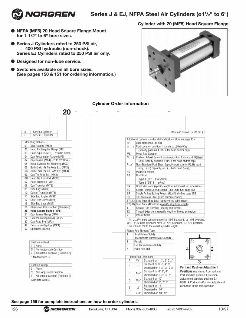
● NFPA (MF5) 20 Head Square Flange Mountfor 1-1/2" to 6" bore sizes.
● Series J Cylinders rated to 250 PSI air,400 PSI hydraulic (non-shock).
Series EJ Cylinders rated to 250 PSI air only.
● Designed for non-lube service.
● Switches available on all bore sizes.(See pages 150 & 151 for ordering information.)
Series J & EJ, NFPA Steel Air Cylinders (ø11/2" to 6")
Cylinder with 20 (MF5) Head Square Flange
10/97126 Brookville, OH USA Phone 937-833-4033 Fax 937-833-4205
See page 156 for complete instructions on how to order cylinders.
Cylinder Order Information
Additional Options – order alphabetically – More on page 155HR Case Hardened (45 Rc)L(_ _) Port Location position 1 standard: L(Head Cap)
(specify position 1 thru 4 for head and/or cap)MS Metal Rod ScraperN(_ _) Cushion Adjust Screw Location position 2 standard: N(Head
Cap) (specify position 1 thru 4 for head and/or cap)P(_)* Non-Standard Port Sizes: [specify port size for P(_H) head
only, P(_C) cap only, or P(_) both head & cap]PS Magnetic Piston RS Rod Stud
Type 1 (5/8" – 13/4" øRod)Type 2 (5/8" & 1" øRod)
RX Rod Extensions (specify length of additional rod extension)SC Single Acting Spring Extend (Cap End)–See page 155SR Single Acting Spring Retract (Rod End)–See page 155SS 303 Stainless Steel (Hard Chrome Plated)ST(_C) Stop Tube (Cap End) (specify stop tube length)ST(_R) Stop Tube (Rod End) (specify stop tube length) T Special Rod Threads (specify rod thread)TX Thread Extensions (specify length of thread extension)V Viton® Seals
*11/2", 2", 21/2" bore cylinders have 3/8" NPT Standard, 1/2" NPT oversize. 31/4", 4", 5" bore cylinders have 1/2" NPT Standard, 3/4" NPT oversize.This will add 1/8" to the overall cylinder length.
Mounting Options01 Side Tapped (MS4)03 Head Rectangular Flange (MF1)03 Head Square (ME3) –7" to12" Bores04 Cap Rectangular Flange (MF2)04 Cap Square (ME4) –7" to 12" Bores05 Basic Cylinder No Mounting (MX0)06 Both Ends (4) Tie Rods Ext. (MX1)6B Both Ends (2) Tie Rods Ext. (MX4)6C Cap Tie Rods Ext. (MX2)6R Head Tie Rods Ext. (MX3)07 Head Trunnion (MT1)08 Cap Trunnion (MT2)09 Side Lugs (MS2)10 Center Trunnion (MT4)11 Side End Angles (MS1)12 Cap Fixed Clevis (MP1)15 Side End Lugs (MS7)16 Sleeve Nut Construction (Universal)20 Head Square Flange (MF5)21 Cap Square Flange (MF6)22 Detachable Cap Clevis (MP2)32 Cap Fixed Eye (MP3)42 Detachable Cap Eye (MP4)52 Spherical Bearing
J Series J CylinderEJ Series EJ Cylinder
20 – – – –
Bore and Stroke (write out )
†Standard with EJ
†Standard with EJ
1
3
4 2
Cushion in Head 3 None5† Non-Adjustable Cushion7 Adjustable Cushion (Position 2)
Cushion in Cap 3 None5† Non-Adjustable Cushion7 Adjustable Cushion (Position 2)
Piston Rod Threads Type1 Small Male (Solid)2 Intermediate Thread Male (Solid)3 Female6 Full Thread Male (Solid)7 Plain Rod End
Port and Cushion AdjustmentPositions (As viewed from rod end:Port standard position 1, CushionAdjustment standard position 2.)NOTE: A Port and a Cushion Adjustmentcannot be in the same position.
Piston Rod DiametersA 5/8" Standard on 11/2", 2", 21/2"
Standard on 31/4", 4", 5"B 1"
Oversized on 11/2", 2", 21/2"Standard on 6", 7", 8"
C 13/8"Oversized on 31/4", 4", 5"Standard on 10"
D 13/4"Oversized on 6", 7", 8"Standard on 12"
E 2"Oversized on 10"
F 21/2" Oversized on 10", 12"

(15.88) (15.88) (15.88) (25.40) (25.40) (25.40) (34.93) (34.93)(25.40) (25.40) (25.40) (34.93) (34.93) (34.93) (44.45) (44.45)(19.05) (19.05) (19.05) (28.58) (28.58) (28.58) (41.28) (41.28)(28.58) (28.58) (28.58) (41.28) (41.28) (41.28) (50.80) (50.80)(28.55) (28.55) (28.55) (38.08) (38.08) (38.08) (50.78) (50.78)(38.08) (38.08) (38.08) (50.78) (50.78) (50.78) (60.30) (60.30)(9.53) (9.53) (9.53) (12.70) (12.70) (12.70) (15.88) (15.88)
(12.70) (12.70) (12.70) (15.88) (15.88) (15.88) (19.05) (19.05)
(12.70) (12.70) (12.70) (20.64) (20.64) (20.64) (28.58) (28.58)(20.64) (20.64) (20.64) (28.58) (28.58) (28.58) (38.10) (38.10)(50.80) (63.50) (76.20) (95.25) (114.30) (139.70) (165.10) (215.90)(9.53) (9.53) (9.53) (12.70) (12.70) (12.70) (19.05) (19.05)(9.53) (9.53) (9.53) (15.88) (15.88) (15.88) (19.05)(7.94) (9.53) (9.53) (11.11) (11.11) (14.29) (14.29) (17.45)
(38.10) (38.10) (38.10) (44.45) (44.45) (44.45) (50.80) (50.80)(25.40) (25.40) (25.40) (31.75) (31.75) (31.75) (38.10) (38.10)(6.35) (7.94) (7.94) (9.53) (9.53) (11.11) (11.11) (14.29)
(92.08) (92.08) (95.25) (107.95) (107.95) (114.30) (127.00) (130.18)(15.88) (15.88) (15.88) (25.40) (25.40) (25.40) (34.93) (34.42)(25.40) (25.40) (25.40) (34.93) (34.93) (34.93) (44.45) (43.94)(58.74) (58.74) (61.91) (66.68) (66.68) (73.03) (79.38) (82.55)(36.27) (46.68) (55.67) (70.05) (84.40) (104.16) (123.92) (163.44)(69.85) (85.73) (98.43) (119.06) (138.11) (168.28) (193.68)(85.73) (104.78) (117.48) (139.70) (158.75) (193.68) (219.08)(6.35) (6.35) (6.35) (6.35) (6.35) (6.35) (6.35) (9.53)
(12.70) (12.70) (12.70) (9.53) (9.53) (9.53) (9.53) (9.53)(15.88) (15.88) (15.88) (19.05) (19.05) (19.05) (22.23) (41.28)(25.40) (25.40) (25.40) (25.40) (25.40) (25.40) (28.58) (47.63)(25.40) (25.40) (25.40) (34.92) (34.92) (34.92) (41.27)(34.92) (34.92) (34.92) (41.27) (41.27) (41.27) (47.63)(47.63) (47.63) (47.63) (61.91) (61.91) (61.91) (71.44) (71.44)(57.15) (57.15) (57.15) (68.26) (68.26) (68.26) (77.79) (77.79)
(123.83) (125.41) (128.59) (152.40) (152.40) (160.34) (179.39) (185.74)(133.35) (134.94) (138.11) (158.75) (158.75) (166.69) (185.74) (193.68)
.5/8" .5/8" .5/8" .1" .1" .1" 1.3/8" 1.3/8"
.1" .1" .1" 1.3/8" 1.3/8" 1.3/8" 1.3/4" 1.3/4"
.750 .750 .750 1.125 1.125 1.125 1.625 1.6251.125 1.125 1.125 1.625 1.625 1.625 2.000 2.0001.124 1.124 1.124 1.499 1.499 1.499 1.999 1.9991.499 1.499 1.499 1.999 1.999 1.999 2.374 2.374.375 .375 .375 .500 .500 .500 .625 .625.500 .500 .500 .625 .625 .625 .750 .750
.500 .500 .500 .813 .813 .813 1.125 1.125
.813 .813 .813 1.125 1.125 1.125 1.500 1.5002.000 2.500 3.000 3.750 4.500 5.500 6.500 8.500.375 .375 .375 .500 .500 .500 .750 .750.375 .375 .375 .625 .625 .625 .750.313 .375 .375 .438 .438 .563 .563 .688
1.500 1.500 1.500 1.750 1.750 1.750 2.000 2.0001.000 1.000 1.000 1.250 1.250 1.250 1.500 1.500.250 .313 .313 .375 .375 .438 .438 .563
3.625 3.625 3.750 4.250 4.250 4.500 5.000 5.125.625 .625 .625 1.000 1.000 1.000 1.375 1.355
1.000 1.000 1.000 1.375 1.375 1.375 1.750 1.7302.313 2.313 2.438 2.625 2.625 2.875 3.125 3.2501.428 1.838 2.192 2.758 3.323 4.101 4.879 6.4352.750 3.375 3.875 4.688 5.438 6.625 7.6253.375 4.125 4.625 5.500 6.250 7.625 8.625.250 .250 .250 .250 .250 .250 .250 .375.500 .500 .500 .375 .375 .375 .375 .375.625 .625 .625 .750 .750 .750 .875 1.625
1.000 1.000 1.000 1.000 1.000 1.000 1.125 1.8751.000 1.000 1.000 1.375 1.375 1.375 1.6251.375 1.375 1.375 1.625 1.625 1.625 1.8751.875 1.875 1.875 2.438 2.438 2.438 2.813 2.8132.250 2.250 2.250 2.688 2.688 2.688 3.063 3.0634.875 4.938 5.063 6.000 6.000 6.313 7.063 7.3135.250 5.313 5.438 6.250 6.250 6.563 7.313 7.625
Dimension 11/2" Bore (38.10) 2" Bore (50.80) 21/2" Bore (63.50) 31/4" Bore (82.55) 4" Bore (101.60) 5" Bore (127.00) 6" Bore (152.40) 8" Bore (203.20)
ø RodStd.O.S.
A Std.O.S.
B+.000 Std.-.002 O.S.
CStd.O.S.
CCStd. 1/2 – 20 1/2 – 20 1/2 – 20 7/8 – 14 7/8 – 14 7/8 – 14 11/4 – 12 11/4 – 12O.S. 7/8 – 14 7/8 – 14 7/8 – 14 11/4 – 12 11/4 – 12 11/4 – 12 11/2 – 12 11/2 – 12
DStd.O.S.
EEEF –FB
FFStd. 5/8 –18 5/8 –18 5/8 –18 1 – 14 1 – 14 1 – 14 13/8 – 12 13/8 – 12O.S. 1 – 14 1 – 14 1 – 14 13/8 – 12 13/8 – 12 13/8 – 12 13/4 – 12 13/4 – 12
GJK
KK Std. 7/16 – 20 7/16 – 20 7/16 – 20 3/4 – 16 3/4 – 16 3/4 – 16 1 – 14 1 – 14O.S. 3/4 –16 3/4 –16 3/4 –16 1 – 14 1 – 14 1 – 14 11/4 – 12 11/4 – 12
LB
MMStd.O.S.
PRTF –UF –
VStd.O.S.
WStd.O.S.
WFStd. –O.S. –
Y Std.O.S.
ZBStd.
12710/97 Brookville, OH USA Phone 937-833-4033 Fax 937-833-4205
Series J & EJ, NFPA Steel Air Cylinder with 20 (MF5) Head Square FlangeAll Dimensions in Inches (mm)
Standard &Optional Rod Ends
Type 2 Studded(Intermediate Thread
Male Optional)
Type 1 Studded (Studded Male Optional)
Type 3 Female(Optional)
Type 2 Solid(Intermediate Thread
Male Optional)
Type 6 Solid(Full Thread
Male Optional)
CCThds.
A
øB
øMM
F
A
øMM
øBKK Thds.
F KKThds.A Deep
øB
øMM
FCCThds.
A
øB
øMM
F FFThds.
A
øB
øMM
F
DAcrossFlats
A
øMM
Fø B
KK Thds.
Type 1 Solid (Standard Male)
VC
VC
VC
VC
VC
VC
C
V
G
ZB + Stroke
LB + Stroke
JK
P + StrokeY
øB Bushing
øMMKKThds
F
A
W
WF
UF TF
D(Flats)
R
E
FB Holes (8)EE NPT (2)

● NFPA (MF6) 21 Cap Square Flange Mount for 1-1/2" to 6" bore sizes.
● Series J Cylinders rated to 250 PSI air,400 PSI hydraulic (non-shock).
Series EJ Cylinders rated to 250 PSI air only.
● Designed for non-lube service.
● Switches available on all bore sizes.(See pages 150 & 151 for ordering information.)
Series J & EJ, NFPA Steel Air Cylinders (ø11/2" to 6")
Cylinder with 21 (MF6) Cap Square Flange
10/97128 Brookville, OH USA Phone 937-833-4033 Fax 937-833-4205
See page 156 for complete instructions on how to order cylinders.
Additional Options – order alphabetically – More on page 155HR Case Hardened (45 Rc)L(_ _) Port Location position 1 standard: L(Head Cap)
(specify position 1 thru 4 for head and/or cap)MS Metal Rod ScraperN(_ _) Cushion Adjust Screw Location position 2 standard: N(Head
Cap) (specify position 1 thru 4 for head and/or cap)P(_)* Non-Standard Port Sizes: [specify port size for P(_H) head
only, P(_C) cap only, or P(_) both head & cap]PS Magnetic Piston RS Rod Stud
Type 1 (5/8" – 13/4" øRod)Type 2 (5/8" & 1" øRod)
RX Rod Extensions (specify length of additional rod extension)SC Single Acting Spring Extend (Cap End)–See page 155SR Single Acting Spring Retract (Rod End)–See page 155SS 303 Stainless Steel (Hard Chrome Plated)ST(_C) Stop Tube (Cap End) (specify stop tube length)ST(_R) Stop Tube (Rod End) (specify stop tube length) T Special Rod Threads (specify rod thread)TX Thread Extensions (specify length of thread extension)V Viton® Seals
*11/2", 2", 21/2" bore cylinders have 3/8" NPT Standard, 1/2" NPT oversize. 31/4", 4", 5" bore cylinders have 1/2" NPT Standard, 3/4" NPT oversize.This will add 1/8" to the overall cylinder length.
Mounting Options01 Side Tapped (MS4)03 Head Rectangular Flange (MF1)03 Head Square (ME3) –7" to12" Bores04 Cap Rectangular Flange (MF2)04 Cap Square (ME4) –7" to 12" Bores05 Basic Cylinder No Mounting (MX0)06 Both Ends (4) Tie Rods Ext. (MX1)6B Both Ends (2) Tie Rods Ext. (MX4)6C Cap Tie Rods Ext. (MX2)6R Head Tie Rods Ext. (MX3)07 Head Trunnion (MT1)08 Cap Trunnion (MT2)09 Side Lugs (MS2)10 Center Trunnion (MT4)11 Side End Angles (MS1)12 Cap Fixed Clevis (MP1)15 Side End Lugs (MS7)16 Sleeve Nut Construction (Universal)20 Head Square Flange (MF5)21 Cap Square Flange (MF6)22 Detachable Cap Clevis (MP2)32 Cap Fixed Eye (MP3)42 Detachable Cap Eye (MP4)52 Spherical Bearing
J Series J CylinderEJ Series EJ Cylinder
21 – – – –
Bore and Stroke (write out )
†Standard with EJ
†Standard with EJ
1
3
4 2
Cushion in Head 3 None5† Non-Adjustable Cushion7 Adjustable Cushion (Position 2)
Cushion in Cap 3 None5† Non-Adjustable Cushion7 Adjustable Cushion (Position 2)
Piston Rod Threads Type1 Small Male (Solid)2 Intermediate Thread Male (Solid)3 Female6 Full Thread Male (Solid)7 Plain Rod End
Port and Cushion AdjustmentPositions (As viewed from rod end:Port standard position 1, CushionAdjustment standard position 2.)NOTE: A Port and a Cushion Adjustmentcannot be in the same position.
Piston Rod DiametersA 5/8" Standard on 11/2", 2", 21/2"
Standard on 31/4", 4", 5"B 1"
Oversized on 11/2", 2", 21/2"Standard on 6", 7", 8"
C 13/8"Oversized on 31/4", 4", 5"Standard on 10"
D 13/4"Oversized on 6", 7", 8"Standard on 12"
E 2"Oversized on 10"
F 21/2" Oversized on 10", 12"
Cylinder Order Information

Dimension 11/2" Bore (38.10) 2" Bore (50.80) 21/2" Bore (63.50) 31/4" Bore (82.55) 4" Bore (101.60) 5" Bore (127.00) 6" Bore (152.40) 8" Bore (203.20)
ø RodStd.O.S.
A Std.O.S.
B+.000 Std.-.002 O.S.
CStd.O.S.
CCStd. 1/2 – 20 1/2 – 20 1/2 – 20 7/8 – 14 7/8 – 14 7/8 – 14 11/4 – 12 11/4 – 12O.S. 7/8 – 14 7/8 – 14 7/8 – 14 11/4 – 12 11/4 – 12 11/4 – 12 11/2 – 12 11/2 – 12
DStd.O.S.
EEEFFB
FFStd. 5/8 – 18 5/8 – 18 5/8 – 18 1 – 14 1 – 14 1 – 14 13/8 – 12 13/8 – 12O.S. 1 – 14 1 – 14 1 – 14 13/8 – 12 13/8 – 12 13/8 – 12 13/4 – 12 13/4 – 12
GJK
KK Std. 7/16 – 20 7/16 – 20 7/16 – 20 3/4 – 16 3/4 – 16 3/4 – 16 1 – 14 1 – 14O.S. 3/4 – 16 3/4 – 16 3/4 – 16 1 – 14 1 – 14 1 – 14 11/4 – 12 11/4 – 12
LB
MMStd.O.S.
PRTF –UF –
VFStd.O.S.
WF Std.O.S.
XF Std.O.S.
YStd.O.S.
ZFStd.O.S.
(15.88) (15.88) (15.88) (25.40) (25.40) (25.40) (34.93) (34.93)(25.40) (25.40) (25.40) (34.93) (34.93) (34.93) (44.45) (44.45)(19.05) (19.05) (19.05) (28.58) (28.58) (28.58) (41.28) (41.28)(28.58) (28.58) (28.58) (41.28) (41.28) (41.28) (50.80) (50.80)(28.55) (28.55) (28.55)) (38.08) (38.08) (38.08) (50.78) (50.78)(38.08) (38.08) (38.08) (50.78) (50.78) (50.78) (60.30) (60.30)(9.53) (9.53) (9.53) (12.70) (12.70) (12.70) (15.88) (15.88)
(12.70) (12.70) (12.70) (15.88) (15.88) (15.88) (19.05) (19.05)
(12.70) (12.70) (12.70) (20.64) (20.64) (20.64) (28.58) (28.58)(20.64) (20.64) (20.64) (28.58) (28.58) (28.58) (38.10) (38.10)(50.80) (63.50) (76.20) (95.25) (114.30) (139.70) (165.10) (215.90)(9.53) (9.53) (9.53) (12.70) (12.70) (12.70) (19.05) (19.05)(9.53) (9.53) (9.53) (15.88) (15.88) (15.88) (19.05)(7.94) (9.53) (9.53) (11.11) (11.11) (14.29) (14.29) (17.45)
(38.10) (38.10) (38.10) (44.45) (44.45) (44.45) (50.80) (50.80)(25.40) (25.40) (25.40) (31.75) (31.75) (31.75) (38.10) (38.10)(6.35) (7.94) (7.94) (9.53) (9.53) (11.11) (11.11) (15.88)
(92.08) (92.08) (95.25) (107.95) (107.95) (114.30) (127.00) (130.18)(15.88) (15.88) (15.88) (25.40) (25.40) (25.40) (34.93) (34.42)(25.40) (25.40) (25.40) (34.93) (34.93) (34.93) (44.45) (43.94)(58.74) (58.74) (61.91) (66.68) (66.68) (73.03) (79.38) (82.55)(36.27) (46.68) (55.67) (70.05) (84.40) (104.16) (123.92) (163.44)(69.85) (85.73) (98.43) (119.06) (138.11) (168.28) (193.68)(85.73) (104.78) (117.48) (139.70) (158.75) (193.68) (219.08)(15.88) (15.88) (15.88) (22.23) (22.23) (22.23) (25.40) (9.53)(22.23) (22.23) (22.23) (25.40) (25.40) (25.40) (28.58) (9.53)(25.40) (25.40) (25.40) (34.92) (34.92) (34.92) (41.27)(34.92) (34.92) (34.92) (41.27) (41.27) (41.27) (47.63)
(117.48) (117.48) (120.65) (142.88) (142.88) (149.23) (168.27)(127.00) (127.00) (130.18) (149.23) (149.23) (155.58) (174.63)(47.63) (47.63) (47.63) (61.91) (61.91) (63.91) (71.44) (71.44)(57.15) (57.15) (57.15) (68.26) (68.26) (68.26) (77.79) (77.80)
(127.00) (127.00) (130.18) (158.75) (158.75) (165.10) (187.33) (171.45)(136.53) (136.53) (139.70) (165.10) (165.10) (171.45) (193.68) (177.80)
.5/8" .5/8" .5/8" .1" .1" .1" 1.3/8" 1.3/8"
.1" .1" .1" 1.3/8" 1.3/8" 1.3/8" 1.3/4" 1.3/4"
.750 .750 .750 1.125 1.125 1.125 1.625 1.6251.125 1.125 1.125 1.625 1.625 1.625 2.000 2.0001.124 1.124 1.124 1.499 1.499 1.499 1.999 1.9991.499 1.499 1.499 1.999 1.999 1.999 2.374 2.374.375 .375 .375 .500 .500 .500 .625 .625.500 .500 .500 .625 .625 .625 .750 .750
.500 .500 .500 .813 .813 .813 1.125 1.125
.813 .813 .813 1.125 1.125 1.125 1.500 1.5002.000 2.500 3.000 3.750 4.500 5.500 6.500 8.500.375 .375 .375 .500 .500 .500 .750 .750.375 .375 .375 .625 .625 .625 .750.313 .375 .375 .438 .438 .563 .563 .687
1.500 1.500 1.500 1.750 1.750 1.750 2.000 2.0001.000 1.000 1.000 1.250 1.250 1.250 1.500 1.500.250 .313 .313 .375 .375 .438 .438 .625
3.625 3.625 3.750 4.250 4.250 4.500 5.000 5.125.625 .625 .625 1.000 1.000 1.000 1.375 1.355
1.000 1.000 1.000 1.375 1.375 1.375 1.750 1.7302.313 2.313 2.438 2.625 2.625 2.875 3.125 3.2501.428 1.838 2.192 2.758 3.323 4.101 4.879 6.4352.750 3.375 3.875 4.688 5.438 6.625 7.6253.375 4.125 4.625 5.500 6.250 7.625 8.625.625 .625 .625 .875 .875 .875 1.000 1.000.875 .875 .875 1.000 1.000 1.000 1.125 1.000
1.000 1.000 1.000 1.375 1.375 1.375 1.6251.375 1.375 1.375 1.625 1.625 1.625 1.8754.625 4.625 4.750 5.625 5.625 5.875 6.6255.000 5.000 5.125 5.875 5.875 6.125 6.8751.875 1.875 1.875 2.438 2.438 2.438 2.813 2.8132.250 2.250 2.250 2.688 2.688 2.688 3.063 3.0635.000 5.000 5.125 6.250 6.250 6.500 7.375 6.7505.375 5.375 5.500 6.500 6.500 6.750 7.625 7.000
12910/97 Brookville, OH USA Phone 937-833-4033 Fax 937-833-4205
Series J & EJ, NFPA Steel Air Cylinder with 21 (MF6) Cap Square FlangeAll Dimensions in Inches (mm)
Standard &Optional Rod Ends
CCThds.
A
ø B
øMM
A
øMM
ø BKK Thds.
KKThds.A Deep
ø B
øMM
CCThds.
A
ø B
øMM
FFThds.
ø B
øMM
Type 2 Studded(Intermediate Thread
Male Optional)
Type 3 Female(Optional)
Type 2 Solid(Intermediate Thread
Male Optional)
Type 6 Solid(Full Thread
Male Optional)
DAcrossFlats
A
øMM
ø BKK Thds.
Type 1 Studded (Studded Male Optional)
Type 1 Solid (Standard Male)
CVF
CVF
CVF
CVF
CVF
A
CVF
UFTF
FB Holes (8)EE NPT (2)
A
C
VF
G
ZF + Stroke
LB + Stroke
JF
P + StrokeY
øB Bushing
øMM
KKThds
WF
R
E
XF + Stroke

● NFPA (MP2) 22 Detachable Cap Clevis Mountfor 1-1/2" to 8" bore sizes.
● Series J Cylinders rated to 250 PSI air,400 PSI hydraulic (non-shock).
Series EJ Cylinders rated to 250 PSI air only.
● Designed for non-lube service.
● Switches available on all bore sizes.(See pages 150 & 151 for ordering information.)
Series J & EJ, NFPA Steel Air Cylinders (ø11/2" to 8")
Cylinder with 22 (MP2) Detachable Cap Clevis
10/97130 Brookville, OH USA Phone 937-833-4033 Fax 937-833-4205
See page 156 for complete instructions on how to order cylinders.
Cylinder Order Information
Additional Options – order alphabetically – More on page 155HR Case Hardened (45 Rc)L(_ _) Port Location position 1 standard: L(Head Cap)
(specify position 1 thru 4 for head and/or cap)MS Metal Rod ScraperN(_ _) Cushion Adjust Screw Location position 2 standard: N(Head
Cap) (specify position 1 thru 4 for head and/or cap)P(_)* Non-Standard Port Sizes: [specify port size for P(_H) head
only, P(_C) cap only, or P(_) both head & cap]PS Magnetic Piston RS Rod Stud
Type 1 (5/8" – 13/4" øRod)Type 2 (5/8" & 1" øRod)
RX Rod Extensions (specify length of additional rod extension)SC Single Acting Spring Extend (Cap End)–See page 155SR Single Acting Spring Retract (Rod End)–See page 155SS 303 Stainless Steel (Hard Chrome Plated)ST(_C) Stop Tube (Cap End) (specify stop tube length)ST(_R) Stop Tube (Rod End) (specify stop tube length) T Special Rod Threads (specify rod thread)TX Thread Extensions (specify length of thread extension)V Viton® Seals
*11/2", 2", 21/2" bore cylinders have 3/8" NPT Standard, 1/2" NPT oversize. 31/4", 4", 5" bore cylinders have 1/2" NPT Standard, 3/4" NPT oversize.This will add 1/8" to the overall cylinder length.
Mounting Options01 Side Tapped (MS4)03 Head Rectangular Flange (MF1)03 Head Square (ME3) –7" to12" Bores04 Cap Rectangular Flange (MF2)04 Cap Square (ME4) –7" to 12" Bores05 Basic Cylinder No Mounting (MX0)06 Both Ends (4) Tie Rods Ext. (MX1)6B Both Ends (2) Tie Rods Ext. (MX4)6C Cap Tie Rods Ext. (MX2)6R Head Tie Rods Ext. (MX3)07 Head Trunnion (MT1)08 Cap Trunnion (MT2)09 Side Lugs (MS2)10 Center Trunnion (MT4)11 Side End Angles (MS1)12 Cap Fixed Clevis (MP1)15 Side End Lugs (MS7)16 Sleeve Nut Construction (Universal)20 Head Square Flange (MF5)21 Cap Square Flange (MF6)22 Detachable Cap Clevis (MP2)32 Cap Fixed Eye (MP3)42 Detachable Cap Eye (MP4)52 Spherical Bearing
J Series J CylinderEJ Series EJ Cylinder
22 – – – –
Bore and Stroke (write out )
†Standard with EJ
†Standard with EJ
1
3
4 2
Cushion in Head 3 None5† Non-Adjustable Cushion7 Adjustable Cushion (Position 2)
Cushion in Cap 3 None5† Non-Adjustable Cushion7 Adjustable Cushion (Position 2)
Piston Rod Threads Type1 Small Male (Solid)2 Intermediate Thread Male (Solid)3 Female6 Full Thread Male (Solid)7 Plain Rod End
Port and Cushion AdjustmentPositions (As viewed from rod end:Port standard position 1, CushionAdjustment standard position 2.)NOTE: A Port and a Cushion Adjustmentcannot be in the same position.
Piston Rod DiametersA 5/8" Standard on 11/2", 2", 21/2"
Standard on 31/4", 4", 5"B 1"
Oversized on 11/2", 2", 21/2"Standard on 6", 7", 8"
C 13/8"Oversized on 31/4", 4", 5"Standard on 10"
D 13/4"Oversized on 6", 7", 8"Standard on 12"
E 2"Oversized on 10"
F 21/2" Oversized on 10", 12"

(15.88) (15.88) (15.88) (25.40) (25.40) (25.40) (34.93) (34.93) (34.93)(25.40) (25.40) (25.40) (34.93) (34.93) (34.93) (44.45) (44.45) (44.45)(19.05) (19.05) (19.05) (28.58) (28.58) (28.58) (41.28) (41.28) (41.28)(28.58) (28.58) (28.58) (41.28) (41.28) (41.28) (50.80) (50.80) (50.80)(28.55) (28.55) (28.55) (38.08) (38.08) (38.08) (50.78) (50.78) (50.78)(38.08) (38.08) (38.08) (50.78) (50.78) (50.78) (60.30) (60.30) (60.30)(9.53) (9.53) (9.53) (12.70) (12.70) (12.70) (15.88) (15.88) (15.88)
(12.70) (12.70) (12.70) (15.88) (15.88) (15.88) (19.05) (19.05) (19.05)(19.05) (19.05) (19.05) (31.75) (31.75) (31.75) (38.10) (38.10) (38.10)
(12.70) (12.70) (12.70) (19.05) (19.05) (19.05) (25.40) (25.40) (25.40)(12.70) (12.70) (12.70) (15.88) (15.88) (15.88) (19.05) (19.05) (19.05)(12.70) (12.70) (12.70) (20.64) (20.64) (20.64) (28.58) (28.58) (28.58)(20.64) (20.64) (20.64) (28.58) (28.58) (28.58) (38.10) (38.10) (38.10)(50.80) (63.50) (76.20) (95.25) (114.30) (139.70) (165.10) (190.50) (215.90)(9.53) (9.53) (9.53) (12.70) (12.70) (12.70) (19.05) (19.05) (19.05)
(28.58) (28.58) (28.58) (47.63) (47.63) (47.63) (57.15) (57.15) (57.15)(38.10) (38.10) (38.10) (44.45) (44.45) (44.45) (50.80) (50.80) (50.80)(25.40) (25.40) (25.40) (31.75) (31.75) (31.75) (38.10) (38.10) (38.10)(6.35) (7.94) (7.94) (9.53) (9.53) (11.11) (11.11) (14.29) (14.29)
(19.05) (19.05) (19.05) (31.75) (31.75) (31.75) (38.10) (38.10) (38.10)(92.08) (92.08) (95.25) (107.95) (107.95) (114.30) (127.00) (130.18) (130.18)(19.05) (19.05) (19.05) (31.75) (31.75) (31.75) (38.10) (38.10) (38.10)(12.70) (12.70) (12.70) (19.05) (19.05) (19.05) (25.40) (25.40) (25.40)(15.88) (15.88) (15.88) (25.40) (25.40) (25.40) (34.93) (34.93) (34.93)(25.40) (25.40) (25.40) (34.93) (34.93) (34.93) (44.45) (44.45) (44.45)(15.88) (15.88) (15.88) (23.81) (23.81) (23.81) (30.16) (30.16) (30.16)(58.74) (58.74) (61.91) (66.68) (66.68) (73.03) (79.38) (82.55) (82.55)(15.88) (15.88) (15.88) (22.23) (22.23) (22.23) (25.40) (25.40) (25.40)(22.23) (22.23) (22.23) (25.40) (25.40) (25.40) (28.58) (28.58) (28.58)(25.40) (25.40) (25.40) (34.93) (34.93) (34.93) (41.28) (41.28) (41.28)(34.93) (34.93) (34.93) (41.28) (41.28) (41.28) (47.62) (47.62) (47.62)
(146.05) (146.05) (149.23) (190.50) (190.50) (196.85) (225.43) (228.60) (228.60)(155.58) (155.58) (158.75) (196.85) (196.85) (203.20) (231.78) (234.95) (234.95)(47.63) (47.63) (47.63) (61.91) (61.91) (61.91) (71.44) (71.44) (71.44)(57.15) (57.15) (57.15) (68.26) (68.26) (68.26) (77.79) (77.79) (77.79)
.5/8" .5/8" .5/8" .1" .1" .1" 1.3/8" 1.3/8" 1.3/8"
.1" .1" .1" 1.3/8" 1.3/8" 1.3/8" 1.3/4" 1.3/4" 1.3/4"
.750 .750 .750 1.125 1.125 1.125 1.625 1.625 1.6251.125 1.125 1.125 1.625 1.625 1.625 2.000 2.000 2.0001.124 1.124 1.124 1.499 1.499 1.499 1.999 1.999 1.9991.499 1.499 1.499 1.999 1.999 1.999 2.374 2.374 2.374.375 .375 .375 .500 .500 .500 .625 .625 .625.500 .500 .500 .625 .625 .625 .750 .750 .750.750 .750 .750 1.250 1.250 1.250 1.500 1.500 1.500
.500 .500 .500 .750 .750 .750 1.000 1.000 1.000
.500 .500 .500 .625 .625 .625 .750 .750 .750
.500 .500 .500 .813 .813 .813 1.125 1.125 1.125
.813 .813 .813 1.125 1.125 1.125 1.500 1.500 1.5002.000 2.500 3.000 3.750 4.500 5.500 6.500 7.500 8.500.375 .375 .375 .500 .500 .500 .750 .750 .750
1.125 1.125 1.125 1.875 1.875 1.875 2.250 2.250 2.2501.500 1.500 1.500 1.750 1.750 1.750 2.000 2.000 2.0001.000 1.000 1.000 1.250 1.250 1.250 1.500 1.500 1.500.250 .313 .313 .375 .375 .438 .438 .563 .563
.750 .750 .750 1.250 1.250 1.250 1.500 1.500 1.5003.625 3.625 3.750 4.250 4.250 4.500 5.000 5.125 5.125.750 .750 .750 1.250 1.250 1.250 1.500 1.500 1.500.500 .500 .500 .750 .750 .750 1.000 1.000 1.000.625 .625 .625 1.000 1.000 1.000 1.375 1.375 1.375
1.000 1.000 1.000 1.375 1.375 1.375 1.750 1.750 1.750.625 .625 .625 .938 .938 .938 1.188 1.188 1.188
2.313 2.313 2.438 2.625 2.625 2.875 3.125 3.250 3.250.625 .625 .625 .875 .875 .875 1.000 1.000 1.000.875 .875 .875 1.000 1.000 1.000 1.125 1.125 1.125
1.000 1.000 1.000 1.375 1.375 1.375 1.625 1.625 1.6251.375 1.375 1.375 1.625 1.625 1.625 1.875 1.875 1.8755.750 5.750 5.875 7.500 7.500 7.750 8.875 9.000 9.0006.125 6.125 6.250 7.750 7.750 8.000 9.125 9.250 9.2501.875 1.875 1.875 2.438 2.438 2.438 2.813 2.813 2.8132.250 2.250 2.250 2.688 2.688 2.688 3.063 3.063 3.063
Dimension 11/2" Bore (38.10) 2" Bore (50.80) 21/2" Bore (63.50) 31/4" Bore (82.55) 4" Bore (101.60) 5" Bore (127.00) 6" Bore (152.40) 7" Bore (177.80) 8" Bore (203.20)
ø RodStd.O.S.
A Std.O.S.
B +.000 Std.-.002 O.S.
CStd.O.S.
CB
CCStd. 1/2 – 20 1/2 – 20 1/2 – 20 7/8 – 14 7/8 – 14 7/8 – 14 11/4 – 12 11/4 – 12 11/4 – 12O.S. 7/8 – 14 7/8 – 14 7/8 – 14 11/4 – 12 11/4 – 12 11/4 – 12 11/2 – 12 11/2 – 12 11/2 – 12
CDCW
DStd.O.S.
EEE
FFStd. 5/8 – 18 5/8 – 18 5/8 – 18 1 – 14 1 – 14 1 – 14 13/8 – 12 13/8 – 12 13/8 – 12O.S. 1 – 14 1 – 14 1 – 14 13/8 – 12 13/8 – 12 13/8 – 12 13/4 – 12 13/4 – 12 13/4 – 12
FLGJK
KK Std. 7/16 – 20 7/16 – 20 7/16 – 20 3/4 – 16 3/4 – 16 3/4 – 16 1 – 14 1 – 14 1 – 14O.S. 3/4 – 16 3/4 – 16 3/4 – 16 1 – 14 1 – 14 1 – 14 11/4 – 12 11/4 – 12 11/4 – 12
LLBLRM
MMStd.O.S.
MRP
VFStd.O.S.
WFStd.O.S.
XDStd.O.S.
Y Std.O.S.
13110/97 Brookville, OH USA Phone 937-833-4033 Fax 937-833-4205
Series J & EJ, NFPA Steel Air Cylinder with 22 (MP2) Detachable Cap ClevisAll Dimensions in Inches (mm)
Standard &Optional Rod Ends
CCThds.
A
ø B
øMM
A
øMM
ø BKK Thds.
KKThds.A Deep
ø B
øMM
CCThds.
A
ø B
øMM
FFThds.
ø B
øMM
Type 2 Studded(Intermediate Thread
Male Optional)
Type 3 Female(Optional)
Type 2 Solid(Intermediate Thread
Male Optional)
Type 6 Solid(Full Thread
Male Optional)
DAcrossFlats
A
øMM
ø BKK Thds.
Type 1 Studded (Studded Male Optional)
Type 1 Solid (Standard Male)
CVF
CVF
CVF
CVF
CVF
A
CVF
A
C
VF
G
XD + Stroke
P + StrokeY
øB Bushing
øMM
KKThds
WF
L
MFL
øCD
MR
LR
CB
EE NPT (2)
E
CW CW
Supplied withStandard Pin(See page 145)

● NFPA (MP3) 32 Cap Fixed Eye for 1-1/2" to 6" bore sizes.
● Series J Cylinders rated to 250 PSI air,400 PSI hydraulic (non-shock).
Series EJ Cylinders rated to 250 PSI air only.
● Designed for non-lube service.
● Switches available on all bore sizes.(See pages 150 & 151 for ordering information.)
Series J & EJ, NFPA Steel Air Cylinders (ø11/2" to 12")
Cylinder with 32 (MP3) Cap Fixed Eye
10/97132 Brookville, OH USA Phone 937-833-4033 Fax 937-833-4205
See page 156 for complete instructions on how to order cylinders.
Additional Options – order alphabetically – More on page 155HR Case Hardened (45 Rc)L(_ _) Port Location position 1 standard: L(Head Cap)
(specify position 1 thru 4 for head and/or cap)MS Metal Rod ScraperN(_ _) Cushion Adjust Screw Location position 2 standard: N(Head
Cap) (specify position 1 thru 4 for head and/or cap)P(_)* Non-Standard Port Sizes: [specify port size for P(_H) head
only, P(_C) cap only, or P(_) both head & cap]PS Magnetic Piston RS Rod Stud
Type 1 (5/8" – 13/4" øRod)Type 2 (5/8" & 1" øRod)
RX Rod Extensions (specify length of additional rod extension)SC Single Acting Spring Extend (Cap End)–See page 155SR Single Acting Spring Retract (Rod End)–See page 155SS 303 Stainless Steel (Hard Chrome Plated)ST(_C) Stop Tube (Cap End) (specify stop tube length)ST(_R) Stop Tube (Rod End) (specify stop tube length) T Special Rod Threads (specify rod thread)TX Thread Extensions (specify length of thread extension)V Viton® Seals
*11/2", 2", 21/2" bore cylinders have 3/8" NPT Standard, 1/2" NPT oversize. 31/4", 4", 5" bore cylinders have 1/2" NPT Standard, 3/4" NPT oversize.This will add 1/8" to the overall cylinder length.
Mounting Options01 Side Tapped (MS4)03 Head Rectangular Flange (MF1)03 Head Square (ME3) –7" to 12" Bores04 Cap Rectangular Flange (MF2)04 Cap Square (ME4) –7" to 12" Bores05 Basic Cylinder No Mounting (MX0)06 Both Ends (4) Tie Rods Ext. (MX1)6B Both Ends (2) Tie Rods Ext. (MX4)6C Cap Tie Rods Ext. (MX2)6R Head Tie Rods Ext. (MX3)07 Head Trunnion (MT1)08 Cap Trunnion (MT2)09 Side Lugs (MS2)10 Center Trunnion (MT4)11 Side End Angles (MS1)12 Cap Fixed Clevis (MP1)15 Side End Lugs (MS7)16 Sleeve Nut Construction (Universal)20 Head Square Flange (MF5)21 Cap Square Flange (MF6)22 Detachable Cap Clevis (MP2)32 Cap Fixed Eye (MP3)42 Detachable Cap Eye (MP4)52 Spherical Bearing
J Series J CylinderEJ Series EJ Cylinder
Cylinder Order Information
32 – – – –
Bore and Stroke (write out )
†Standard with EJ
†Standard with EJ
1
3
4 2
Cushion in Head 3 None5† Non-Adjustable Cushion7 Adjustable Cushion (Position 2)
Cushion in Cap 3 None5† Non-Adjustable Cushion7 Adjustable Cushion (Position 2)
Piston Rod Threads Type1 Small Male (Solid)2 Intermediate Thread Male (Solid)3 Female6 Full Thread Male (Solid)7 Plain Rod End
Port and Cushion AdjustmentPositions (As viewed from rod end:Port standard position 1, CushionAdjustment standard position 2.)NOTE: A Port and a Cushion Adjustmentcannot be in the same position.
Piston Rod DiametersA 5/8" Standard on 11/2", 2", 21/2"
Standard on 31/4", 4", 5"B 1"
Oversized on 11/2", 2", 21/2"Standard on 6", 7", 8"
C 13/8"Oversized on 31/4", 4", 5"Standard on 10"
D 13/4"Oversized on 6", 7", 8"Standard on 12"
E 2"Oversized on 10"
F 21/2" Oversized on 10", 12"
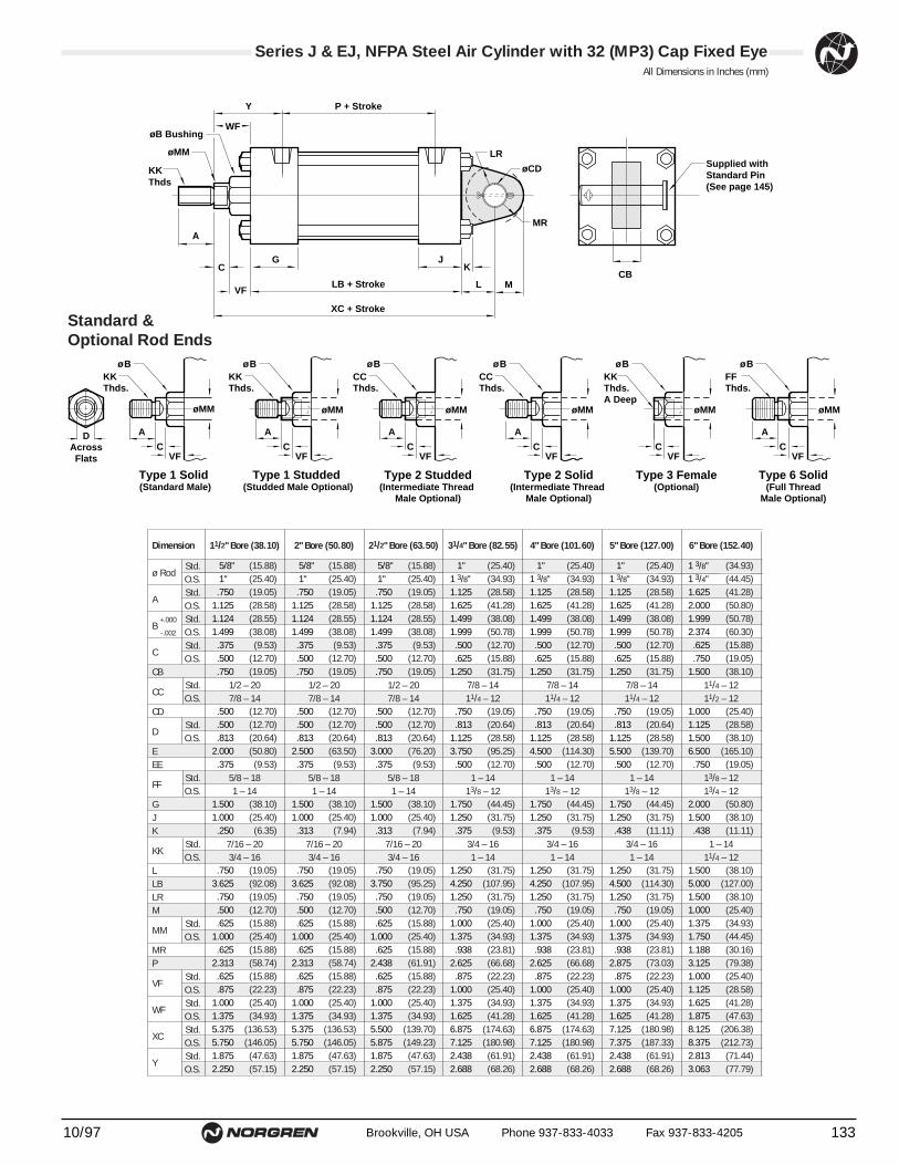
(15.88) (15.88) (15.88) (25.40) (25.40) (25.40) (34.93) (34.93)(25.40) (25.40) (25.40) (34.93) (34.93) (34.93) (44.45) (44.45)(19.05) (19.05) (19.05) (28.58) (28.58) (28.58) (41.28) (41.28)(28.58) (28.58) (28.58) (41.28) (41.28) (41.28) (50.80) (50.80)(28.55) (28.55) (28.55) (38.08) (38.08) (38.08) (50.78) (50.78)(38.08) (38.08) (38.08) (50.78) (50.78) (50.78) (60.30) (60.30)(9.53) (9.53) (9.53) (12.70) (12.70) (12.70) (15.88) (15.88)
(12.70) (12.70) (12.70) (15.88) (15.88) (15.88) (19.05) (19.05)(19.05) (19.05) (19.05) (31.75) (31.75) (31.75) (38.10) (38.10)
(12.70) (12.70) (12.70) (19.05) (19.05) (19.05) (25.40) (25.40)(12.70) (12.70) (12.70) (20.64) (20.64) (20.64) (28.58) (28.58)(20.64) (20.64) (20.64) (28.58) (28.58) (28.58) (38.10) (38.10)(50.80) (63.50) (76.20) (95.25) (114.30) (139.70) (165.10) (190.50)(9.53) (9.53) (9.53) (12.70) (12.70) (12.70) (19.05) (19.05)
(38.10) (38.10) (38.10) (44.45) (44.45) (44.45) (50.80) (50.80)(25.40) (25.40) (25.40) (31.75) (31.75) (31.75) (38.10) (38.10)(6.35) (7.94) (7.94) (9.53) (9.53) (11.11) (11.11) (14.29)
(19.05) (19.05) (19.05) (31.75) (31.75) (31.75) (38.10) (38.10)(92.08) (92.08) (95.25) (107.95) (107.95) (114.30) (127.00) (130.18)(19.05) (19.05) (19.05) (31.75) (31.75) (31.75) (38.10) (38.10)(12.70) (12.70) (12.70) (19.05) (19.05) (19.05) (25.40) (25.40) (15.88) (15.88) (15.88) (25.40) (25.40) (25.40) (34.93) (34.93)(25.40) (25.40) (25.40) (34.93) (34.93) (34.93) (44.45) (44.45)(15.88) (15.88) (15.88) (23.81) (23.81) (23.81) (30.16) (30.16)(58.74) (58.74) (61.91) (66.68) (66.68) (73.03) (79.38) (82.55)(15.88) (15.88) (15.88) (22.23) (22.23) (22.23) (25.40) (25.40)(22.23) (22.23) (22.23) (25.40) (25.40) (25.40) (28.58) (28.58)(25.40) (25.40) (25.40) (34.93) (34.93) (34.93) (41.28) (41.28)(34.93) (34.93) (34.93) (41.28) (41.28) (41.28) (47.63) (47.63)
(136.53) (136.53) (139.70) (174.63) (174.63) (180.98) (206.38) (209.55)(146.05) (146.05) (149.23) (180.98) (180.98) (187.33) (212.73) (215.90)(47.63) (47.63) (47.63) (61.91) (61.91) (61.91) (71.44) (71.44)(57.15) (57.15) (57.15) (68.26) (68.26) (68.26) (77.79) (77.79)
Dimension 11/2" Bore (38.10) 2" Bore (50.80) 21/2" Bore (63.50) 31/4" Bore (82.55) 4" Bore (101.60) 5" Bore (127.00) 6" Bore (152.40) 7" Bore (177.80) 8" Bore (
ø RodStd.O.S.
A Std.O.S.
B +.000 Std.-.002 O.S.
CStd.O.S.
CB
CCStd. 1/2 – 20 1/2 – 20 1/2 – 20 7/8 – 14 7/8 – 14 7/8 – 14 11/4 – 12 11/4 – 12 11/4O.S. 7/8 – 14 7/8 – 14 7/8 – 14 11/4 – 12 11/4 – 12 11/4 – 12 11/2 – 12 11/2 – 12 11/2
CD
DStd.O.S.
EEE
FFStd. 5/8 – 18 5/8 – 18 5/8 – 18 1 – 14 1 – 14 1 – 14 13/8 – 12 13/8 – 12 13/8O.S. 1 – 14 1 – 14 1 – 14 13/8 – 12 13/8 – 12 13/8 – 12 13/4 – 12 13/4 – 12 13/4
GJK
KK Std. 7/16 – 20 7/16 – 20 7/16 – 20 3/4 – 16 3/4 – 16 3/4 – 16 1 – 14 1 – 14 1 –O.S. 3/4 – 16 3/4 – 16 3/4 – 16 1 – 14 1 – 14 1 – 14 11/4 – 12 11/4 – 12 11/4
LLBLRM
MMStd.O.S.
MRP
VFStd.O.S.
WFStd.O.S.
XCStd.O.S.
Y Std.O.S.
.5/8" .5/8" .5/8" .1" .1" .1" 1.3/8" 1.3/8" 1.3/8"
.1" .1" .1" 1.3/8" 1.3/8" 1.3/8" 1.3/4" 1.3/4" 1.3/4"
.750 .750 .750 1.125 1.125 1.125 1.625 1.625 1.6251.125 1.125 1.125 1.625 1.625 1.625 2.000 2.000 2.0001.124 1.124 1.124 1.499 1.499 1.499 1.999 1.999 1.9991.499 1.499 1.499 1.999 1.999 1.999 2.374 2.374 2.374.375 .375 .375 .500 .500 .500 .625 .625 .625.500 .500 .500 .625 .625 .625 .750 .750 .750.750 .750 .750 1.250 1.250 1.250 1.500 1.500 1.500
.500 .500 .500 .750 .750 .750 1.000 1.000 1.000
.500 .500 .500 .813 .813 .813 1.125 1.125 1.125
.813 .813 .813 1.125 1.125 1.125 1.500 1.500 1.5002.000 2.500 3.000 3.750 4.500 5.500 6.500 7.500 8.500.375 .375 .375 .500 .500 .500 .750 .750 .750
1.500 1.500 1.500 1.750 1.750 1.750 2.000 2.000 2.0001.000 1.000 1.000 1.250 1.250 1.250 1.500 1.500 1.500.250 .313 .313 .375 .375 .438 .438 .563 .563
.750 .750 .750 1.250 1.250 1.250 1.500 1.500 1.5003.625 3.625 3.750 4.250 4.250 4.500 5.000 5.125 5.125.750 .750 .750 1.250 1.250 1.250 1.500 1.500 1.500.500 .500 .500 .750 .750 .750 1.000 1.000 1.000.625 .625 .625 1.000 1.000 1.000 1.375 1.375 1.375
1.000 1.000 1.000 1.375 1.375 1.375 1.750 1.750 1.750.625 .625 .625 .938 .938 .938 1.188 1.188 1.188
2.313 2.313 2.438 2.625 2.625 2.875 3.125 3.250 3.250.625 .625 .625 .875 .875 .875 1.000 1.000 1.000.875 .875 .875 1.000 1.000 1.000 1.125 1.125 1.125
1.000 1.000 1.000 1.375 1.375 1.375 1.625 1.625 1.6251.375 1.375 1.375 1.625 1.625 1.625 1.875 1.875 1.8755.375 5.375 5.500 6.875 6.875 7.125 8.125 8.250 8.2505.750 5.750 5.875 7.125 7.125 7.375 8.375 8.500 8.5001.875 1.875 1.875 2.438 2.438 2.438 2.813 2.813 2.8132.250 2.250 2.250 2.688 2.688 2.688 3.063 3.063 3.063
13310/97 Brookville, OH USA Phone 937-833-4033 Fax 937-833-4205
Series J & EJ, NFPA Steel Air Cylinder with 32 (MP3) Cap Fixed EyeAll Dimensions in Inches (mm)
Standard &Optional Rod Ends
CCThds.
A
ø B
øMM
A
øMM
ø BKK Thds.
KKThds.A Deep
ø B
øMM
CCThds.
A
ø B
øMM
FFThds.
ø B
øMM
Type 2 Studded(Intermediate Thread
Male Optional)
Type 3 Female(Optional)
Type 2 Solid(Intermediate Thread
Male Optional)
Type 6 Solid(Full Thread
Male Optional)
DAcrossFlats
A
øMM
ø BKK Thds.
Type 1 Studded (Studded Male Optional)
Type 1 Solid (Standard Male)
CVF
CVF
CVF
CVF
CVF
A
CVF
A
C
VF
G
XC + Stroke
LB + Stroke
P + StrokeY
øB Bushing
øMM
KKThds
WF
L M
J
CBK
øCD
MR
LRSupplied withStandard Pin(See page 145)
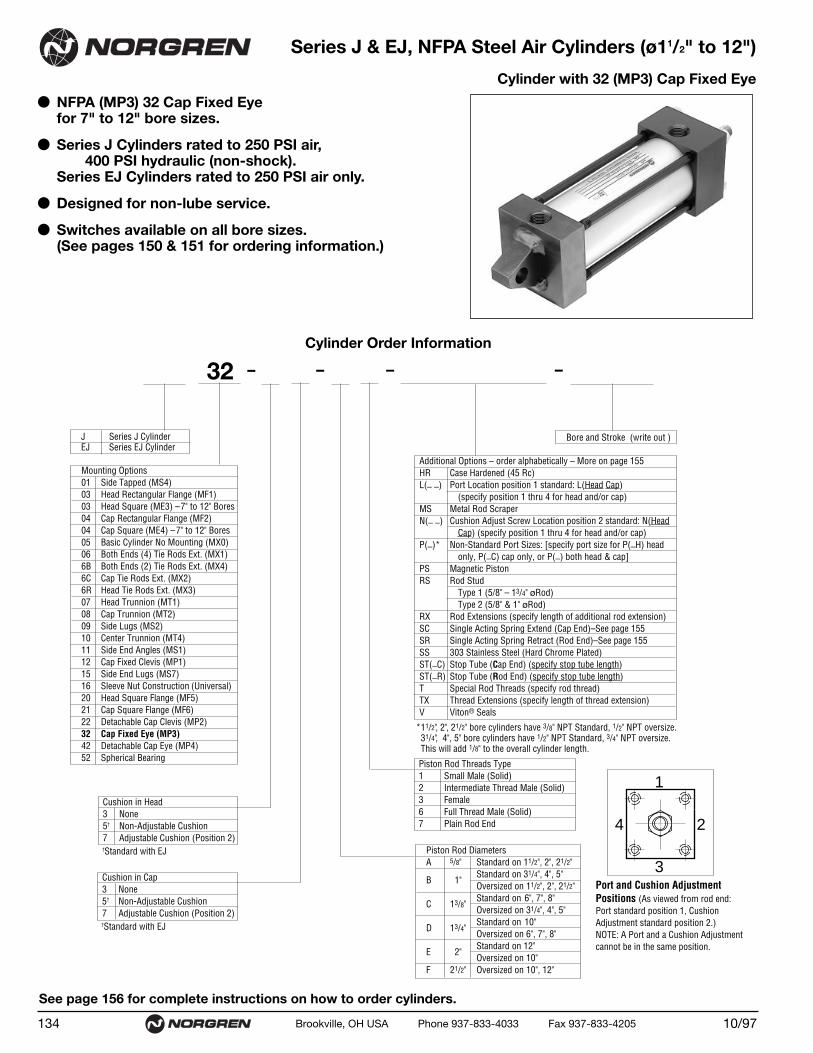
● NFPA (MP3) 32 Cap Fixed Eye for 7" to 12" bore sizes.
● Series J Cylinders rated to 250 PSI air,400 PSI hydraulic (non-shock).
Series EJ Cylinders rated to 250 PSI air only.
● Designed for non-lube service.
● Switches available on all bore sizes.(See pages 150 & 151 for ordering information.)
Series J & EJ, NFPA Steel Air Cylinders (ø11/2" to 12")
Cylinder with 32 (MP3) Cap Fixed Eye
10/97134 Brookville, OH USA Phone 937-833-4033 Fax 937-833-4205
See page 156 for complete instructions on how to order cylinders.
Additional Options – order alphabetically – More on page 155HR Case Hardened (45 Rc)L(_ _) Port Location position 1 standard: L(Head Cap)
(specify position 1 thru 4 for head and/or cap)MS Metal Rod ScraperN(_ _) Cushion Adjust Screw Location position 2 standard: N(Head
Cap) (specify position 1 thru 4 for head and/or cap)P(_)* Non-Standard Port Sizes: [specify port size for P(_H) head
only, P(_C) cap only, or P(_) both head & cap]PS Magnetic Piston RS Rod Stud
Type 1 (5/8" – 13/4" øRod)Type 2 (5/8" & 1" øRod)
RX Rod Extensions (specify length of additional rod extension)SC Single Acting Spring Extend (Cap End)–See page 155SR Single Acting Spring Retract (Rod End)–See page 155SS 303 Stainless Steel (Hard Chrome Plated)ST(_C) Stop Tube (Cap End) (specify stop tube length)ST(_R) Stop Tube (Rod End) (specify stop tube length) T Special Rod Threads (specify rod thread)TX Thread Extensions (specify length of thread extension)V Viton® Seals
*11/2", 2", 21/2" bore cylinders have 3/8" NPT Standard, 1/2" NPT oversize. 31/4", 4", 5" bore cylinders have 1/2" NPT Standard, 3/4" NPT oversize.This will add 1/8" to the overall cylinder length.
Mounting Options01 Side Tapped (MS4)03 Head Rectangular Flange (MF1)03 Head Square (ME3) –7" to 12" Bores04 Cap Rectangular Flange (MF2)04 Cap Square (ME4) –7" to 12" Bores05 Basic Cylinder No Mounting (MX0)06 Both Ends (4) Tie Rods Ext. (MX1)6B Both Ends (2) Tie Rods Ext. (MX4)6C Cap Tie Rods Ext. (MX2)6R Head Tie Rods Ext. (MX3)07 Head Trunnion (MT1)08 Cap Trunnion (MT2)09 Side Lugs (MS2)10 Center Trunnion (MT4)11 Side End Angles (MS1)12 Cap Fixed Clevis (MP1)15 Side End Lugs (MS7)16 Sleeve Nut Construction (Universal)20 Head Square Flange (MF5)21 Cap Square Flange (MF6)22 Detachable Cap Clevis (MP2)32 Cap Fixed Eye (MP3)42 Detachable Cap Eye (MP4)52 Spherical Bearing
J Series J CylinderEJ Series EJ Cylinder
Cylinder Order Information
32 – – – –
Bore and Stroke (write out )
†Standard with EJ
†Standard with EJ
1
3
4 2
Cushion in Head 3 None5† Non-Adjustable Cushion7 Adjustable Cushion (Position 2)
Cushion in Cap 3 None5† Non-Adjustable Cushion7 Adjustable Cushion (Position 2)
Piston Rod Threads Type1 Small Male (Solid)2 Intermediate Thread Male (Solid)3 Female6 Full Thread Male (Solid)7 Plain Rod End
Port and Cushion AdjustmentPositions (As viewed from rod end:Port standard position 1, CushionAdjustment standard position 2.)NOTE: A Port and a Cushion Adjustmentcannot be in the same position.
Piston Rod DiametersA 5/8" Standard on 11/2", 2", 21/2"
Standard on 31/4", 4", 5"B 1"
Oversized on 11/2", 2", 21/2"Standard on 6", 7", 8"
C 13/8"Oversized on 31/4", 4", 5"Standard on 10"
D 13/4"Oversized on 6", 7", 8"Standard on 12"
E 2"Oversized on 10"
F 21/2" Oversized on 10", 12"
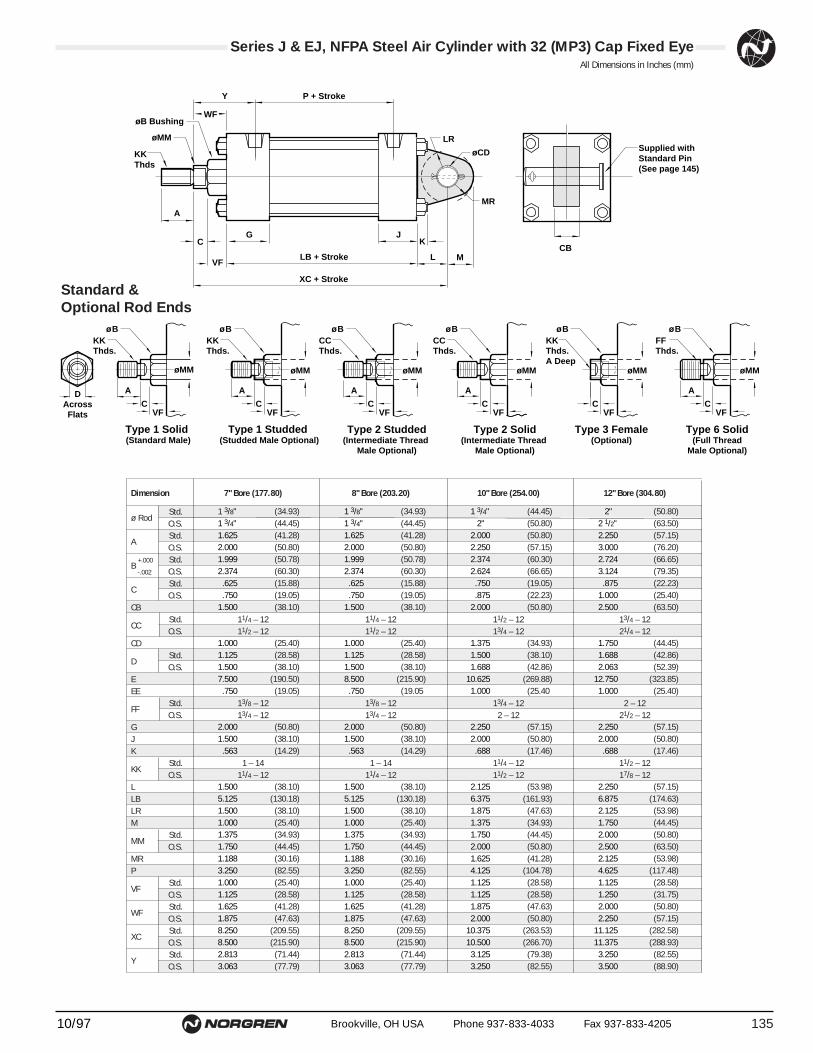
(34.93) (34.93) (44.45) (50.80)(44.45) (44.45) (50.80) (63.50)(41.28) (41.28) (50.80) (57.15)(50.80) (50.80) (57.15) (76.20)(50.78) (50.78) (60.30) (66.65)(60.30) (60.30) (66.65) (79.35)(15.88) (15.88) (19.05) (22.23)(19.05) (19.05) (22.23) (25.40)(38.10) (38.10) (50.80) (63.50)
(25.40) (25.40) (34.93) (44.45)(28.58) (28.58) (38.10) (42.86)(38.10) (38.10) (42.86) (52.39)
(190.50) (215.90) (269.88) (323.85)(19.05) (19.05 (25.40 (25.40)
(50.80) (50.80) (57.15) (57.15)(38.10) (38.10) (50.80) (50.80)(14.29) (14.29) (17.46) (17.46)
(38.10) (38.10) (53.98) (57.15)(130.18) (130.18) (161.93) (174.63)(38.10) (38.10) (47.63) (53.98)(25.40) (25.40) (34.93) (44.45)(34.93) (34.93) (44.45) (50.80)(44.45) (44.45) (50.80) (63.50)(30.16) (30.16) (41.28) (53.98)(82.55) (82.55) (104.78) (117.48)(25.40) (25.40) (28.58) (28.58)(28.58) (28.58) (28.58) (31.75)(41.28) (41.28) (47.63) (50.80)(47.63) (47.63) (50.80) (57.15)
(209.55) (209.55) (263.53) (282.58)(215.90) (215.90) (266.70) (288.93)(71.44) (71.44) (79.38) (82.55)(77.79) (77.79) (82.55) (88.90)
1.3/8" 1.3/8" 1.3/4" .2"1.3/4" 1.3/4" .2" 2.1/2"1.625 1.625 2.000 2.2502.000 2.000 2.250 3.0001.999 1.999 2.374 2.7242.374 2.374 2.624 3.124.625 .625 .750 .875.750 .750 .875 1.000
1.500 1.500 2.000 2.500
1.000 1.000 1.375 1.7501.125 1.125 1.500 1.6881.500 1.500 1.688 2.0637.500 8.500 10.625 12.750.750 .750 1.000 1.000
2.000 2.000 2.250 2.2501.500 1.500 2.000 2.000.563 .563 .688 .688
1.500 1.500 2.125 2.2505.125 5.125 6.375 6.8751.500 1.500 1.875 2.1251.000 1.000 1.375 1.7501.375 1.375 1.750 2.0001.750 1.750 2.000 2.5001.188 1.188 1.625 2.1253.250 3.250 4.125 4.6251.000 1.000 1.125 1.1251.125 1.125 1.125 1.2501.625 1.625 1.875 2.0001.875 1.875 2.000 2.2508.250 8.250 10.375 11.1258.500 8.500 10.500 11.3752.813 2.813 3.125 3.2503.063 3.063 3.250 3.500
Dimension 7" Bore (177.80) 8" Bore (203.20) 10" Bore (254.00) 12" Bore (304.80)
ø RodStd.O.S.
A Std.O.S.
B +.000 Std.-.002 O.S.
CStd.O.S.
CB
CCStd. 11/4 – 12 11/4 – 12 11/2 – 12 13/4 – 12O.S. 11/2 – 12 11/2 – 12 13/4 – 12 21/4 – 12
CD
DStd.O.S.
EEE
FFStd. 13/8 – 12 13/8 – 12 13/4 – 12 2 – 12O.S. 13/4 – 12 13/4 – 12 2 – 12 21/2 – 12
GJK
KK Std. 1 – 14 1 – 14 11/4 – 12 11/2 – 12O.S. 11/4 – 12 11/4 – 12 11/2 – 12 17/8 – 12
LLBLRM
MMStd.O.S.
MRP
VFStd.O.S.
WFStd.O.S.
XCStd.O.S.
Y Std.O.S.
13510/97 Brookville, OH USA Phone 937-833-4033 Fax 937-833-4205
Series J & EJ, NFPA Steel Air Cylinder with 32 (MP3) Cap Fixed EyeAll Dimensions in Inches (mm)
Standard &Optional Rod Ends
CCThds.
A
ø B
øMM
A
øMM
ø BKK Thds.
KKThds.A Deep
ø B
øMM
CCThds.
A
ø B
øMM
FFThds.
ø B
øMM
Type 2 Studded(Intermediate Thread
Male Optional)
Type 3 Female(Optional)
Type 2 Solid(Intermediate Thread
Male Optional)
Type 6 Solid(Full Thread
Male Optional)
DAcrossFlats
A
øMM
ø BKK Thds.
Type 1 Studded (Studded Male Optional)
Type 1 Solid (Standard Male)
CVF
CVF
CVF
CVF
CVF
A
CVF
A
C
VF
G
XC + Stroke
LB + Stroke
P + StrokeY
øB Bushing
øMM
KKThds
WF
L M
J
CBK
øCD
MR
LRSupplied withStandard Pin(See page 145)

● NFPA (MP4) 42 Detachable Cap Eye Mount for 1-1/2" to 8" bore sizes.
● Series J Cylinders rated to 250 PSI air,400 PSI hydraulic (non-shock).
Series EJ Cylinders rated to 250 PSI air only.
● Designed for non-lube service.
● Switches available on all bore sizes.(See pages 150 & 151 for ordering information.)
Series J & EJ, NFPA Steel Air Cylinders (ø11/2" to 8")
Cylinder with 42 (MP4) Detachable Cap Eye
10/97136 Brookville, OH USA Phone 937-833-4033 Fax 937-833-4205
See page 156 for complete instructions on how to order cylinders.
Cylinder Order Information
Additional Options – order alphabetically – More on page 155HR Case Hardened (45 Rc)L(_ _) Port Location position 1 standard: L(Head Cap)
(specify position 1 thru 4 for head and/or cap)MS Metal Rod ScraperN(_ _) Cushion Adjust Screw Location position 2 standard: N(Head
Cap) (specify position 1 thru 4 for head and/or cap)P(_)* Non-Standard Port Sizes: [specify port size for P(_H) head
only, P(_C) cap only, or P(_) both head & cap]PS Magnetic Piston RS Rod Stud
Type 1 (5/8" – 13/4" øRod)Type 2 (5/8" & 1" øRod)
RX Rod Extensions (specify length of additional rod extension)SC Single Acting Spring Extend (Cap End)–See page 155SR Single Acting Spring Retract (Rod End)–See page 155SS 303 Stainless Steel (Hard Chrome Plated)ST(_C) Stop Tube (Cap End) (specify stop tube length)ST(_R) Stop Tube (Rod End) (specify stop tube length) T Special Rod Threads (specify rod thread)TX Thread Extensions (specify length of thread extension)V Viton® Seals
*11/2", 2", 21/2" bore cylinders have 3/8" NPT Standard, 1/2" NPT oversize. 31/4", 4", 5" bore cylinders have 1/2" NPT Standard, 3/4" NPT oversize.This will add 1/8" to the overall cylinder length.
Mounting Options01 Side Tapped (MS4)03 Head Rectangular Flange (MF1)03 Head Square (ME3) –7" to 12" Bores04 Cap Rectangular Flange (MF2)04 Cap Square (ME4) –7" to 12" Bores05 Basic Cylinder No Mounting (MX0)06 Both Ends (4) Tie Rods Ext. (MX1)6B Both Ends (2) Tie Rods Ext. (MX4)6C Cap Tie Rods Ext. (MX2)6R Head Tie Rods Ext. (MX3)07 Head Trunnion (MT1)08 Cap Trunnion (MT2)09 Side Lugs (MS2)10 Center Trunnion (MT4)11 Side End Angles (MS1)12 Cap Fixed Clevis (MP1)15 Side End Lugs (MS7)16 Sleeve Nut Construction (Universal)20 Head Square Flange (MF5)21 Cap Square Flange (MF6)22 Detachable Cap Clevis (MP2)32 Cap Fixed Eye (MP3)42 Detachable Cap Eye (MP4)52 Spherical Bearing
J Series J CylinderEJ Series EJ Cylinder
42 – – – –
Bore and Stroke (write out )
†Standard with EJ
†Standard with EJ
1
3
4 2
Cushion in Head 3 None5† Non-Adjustable Cushion7 Adjustable Cushion (Position 2)
Cushion in Cap 3 None5† Non-Adjustable Cushion7 Adjustable Cushion (Position 2)
Piston Rod Threads Type1 Small Male (Solid)2 Intermediate Thread Male (Solid)3 Female6 Full Thread Male (Solid)7 Plain Rod End
Port and Cushion AdjustmentPositions (As viewed from rod end:Port standard position 1, CushionAdjustment standard position 2.)NOTE: A Port and a Cushion Adjustmentcannot be in the same position.
Piston Rod DiametersA 5/8" Standard on 11/2", 2", 21/2"
Standard on 31/4", 4", 5"B 1"
Oversized on 11/2", 2", 21/2"Standard on 6", 7", 8"
C 13/8"Oversized on 31/4", 4", 5"Standard on 10"
D 13/4"Oversized on 6", 7", 8"Standard on 12"
E 2"Oversized on 10"
F 21/2" Oversized on 10", 12"

(15.88) (15.88) (15.88) (25.40) (25.40) (25.40) (34.93) (34.93) (34.93)(25.40) (25.40) (25.40) (34.93) (34.93) (34.93) (44.45) (44.45) (44.45)(19.05) (19.05) (19.05) (28.58) (28.58) (28.58) (41.28) (41.28) (41.28)(28.58) (28.58) (28.58) (41.28) (41.28) (41.28) (50.80) (50.80) (50.80)(28.55) (28.55) (28.55) (38.08) (38.08) (38.08) (50.78) (50.78) (50.78)(38.08) (38.08) (38.08) (50.78) (50.78) (50.78) (60.30) (60.30) (60.30)(9.53) (9.53) (9.53) (12.70) (12.70) (12.70) (15.88) (15.88) (15.88)
(12.70) (12.70) (12.70) (15.88) (15.88) (15.88) (19.05) (19.05) (19.05)(19.05) (19.05) (19.05) (31.75) (31.75) (31.75) (38.10) (38.10) (38.10)
(12.70) (12.70) (12.70) (19.05) (19.05) (19.05) (25.40) (25.40) (25.40)(12.70) (12.70) (12.70) (20.64) (20.64) (20.64) (28.58) (28.58) (28.58)(20.64) (20.64) (20.64) (28.58) (28.58) (28.58) (38.10) (38.10) (38.10)(50.80) (63.50) (76.20) (95.25) (114.30) (139.70) (165.10) (190.50) (215.90)(9.53) (9.53) (9.53) (12.70) (12.70) (12.70) (19.05) (19.05) (19.05)
(28.58) (28.58) (28.58) (47.63) (47.63) (47.63) (57.15) (57.15) (57.15)(38.10) (38.10) (38.10) (44.45) (44.45) (44.45) (50.80) (50.80) (50.80)(25.40) (25.40) (25.40) (31.75) (31.75) (31.75) (38.10) (38.10) (38.10)(6.35) (7.94) (7.94) (9.53) (9.53) (11.11) (11.11) (14.29) (14.29)
(19.05) (19.05) (19.05) (31.75) (31.75) (31.75) (38.10) (38.10) (38.10)(92.08) (92.08) (95.25) (107.95) (107.95) (114.30) (127.00) (130.18) (130.18)(19.05) (19.05) (19.05) (31.75) (31.75) (31.75) (38.10) (38.10) (38.10)(12.70) (12.70) (12.70) (19.05) (19.05) (19.05) (25.40) (25.40) (25.40)(15.88) (15.88) (15.88) (25.40) (25.40) (25.40) (34.93) (34.93) (34.93)(25.40) (25.40) (25.40) (34.93) (34.93) (34.93) (44.45) (44.45) (44.45)(15.88) (15.88) (15.88) (23.81) (23.81) (23.81) (30.16) (30.16) (30.16)(58.74) (58.74) (61.91) (66.68) (66.68) (73.03) (79.38) (82.55) (82.55)(15.88) (15.88) (15.88) (22.23) (22.23) (22.23) (25.40) (25.40) (25.40)(22.23) (22.23) (22.23) (25.40) (25.40) (25.40) (28.58) (28.58) (28.58)(25.40) (25.40) (25.40) (34.93) (34.93) (34.93) (41.28) (41.28) (41.28)(34.93) (34.93) (34.93) (41.28) (41.28) (41.28) (47.62) (47.62) (47.62)
(146.05) (146.05) (149.23) (190.50) (190.50) (196.85) (225.43) (228.60) (228.60)(155.58) (155.58) (158.75) (196.85) (196.85) (203.20) (231.78) (234.95) (234.95)(47.63) (47.63) (47.63) (61.91) (61.91) (61.91) (71.44) (71.44) (71.44)(57.15) (57.15) (57.15) (68.26) (68.26) (68.26) (77.79) (77.79) (77.79)
.5/8" .5/8" .5/8" .1" .1" .1" 1.3/8" 1.3/8" 1.3/8"
.1" .1" .1" 1.3/8" 1.3/8" 1.3/8" 1.3/4" 1.3/4" 1.3/4"
.750 .750 .750 1.125 1.125 1.125 1.625 1.625 1.6251.125 1.125 1.125 1.625 1.625 1.625 2.000 2.000 2.0001.124 1.124 1.124 1.499 1.499 1.499 1.999 1.999 1.9991.499 1.499 1.499 1.999 1.999 1.999 2.374 2.374 2.374.375 .375 .375 .500 .500 .500 .625 .625 .625.500 .500 .500 .625 .625 .625 .750 .750 .750.750 .750 .750 1.250 1.250 1.250 1.500 1.500 1.500
.500 .500 .500 .750 .750 .750 1.000 1.000 1.000
.500 .500 .500 .813 .813 .813 1.125 1.125 1.125
.813 .813 .813 1.125 1.125 1.125 1.500 1.500 1.5002.000 2.500 3.000 3.750 4.500 5.500 6.500 7.500 8.500.375 .375 .375 .500 .500 .500 .750 .750 .750
1.125 1.125 1.125 1.875 1.875 1.875 2.250 2.250 2.2501.500 1.500 1.500 1.750 1.750 1.750 2.000 2.000 2.0001.000 1.000 1.000 1.250 1.250 1.250 1.500 1.500 1.500.250 .313 .313 .375 .375 .438 .438 .563 .563
.750 .750 .750 1.250 1.250 1.250 1.500 1.500 1.5003.625 3.625 3.750 4.250 4.250 4.500 5.000 5.125 5.125.750 .750 .750 1.250 1.250 1.250 1.500 1.500 1.500.500 .500 .500 .750 .750 .750 1.000 1.000 1.000.625 .625 .625 1.000 1.000 1.000 1.375 1.375 1.375
1.000 1.000 1.000 1.375 1.375 1.375 1.750 1.750 1.750.625 .625 .625 .938 .938 .938 1.188 1.188 1.188
2.313 2.313 2.438 2.625 2.625 2.875 3.125 3.250 3.250.625 .625 .625 .875 .875 .875 1.000 1.000 1.000.875 .875 .875 1.000 1.000 1.000 1.125 1.125 1.125
1.000 1.000 1.000 1.375 1.375 1.375 1.625 1.625 1.6251.375 1.375 1.375 1.625 1.625 1.625 1.875 1.875 1.8755.750 5.750 5.875 7.500 7.500 7.750 8.875 9.000 9.0006.125 6.125 6.250 7.750 7.750 8.000 9.125 9.250 9.2501.875 1.875 1.875 2.438 2.438 2.438 2.813 2.813 2.8132.250 2.250 2.250 2.688 2.688 2.688 3.063 3.063 3.063
Dimension 11/2" Bore (38.10) 2" Bore (50.80) 21/2" Bore (63.50) 31/4" Bore (82.55) 4" Bore (101.60) 5" Bore (127.00) 6" Bore (152.40) 7" Bore (177.80) 8" Bore (203.20)
ø RodStd.O.S.
A Std.O.S.
B +.000 Std.-.002 O.S.
CStd.O.S.
CB
CCStd. 1/2 – 20 1/2 – 20 1/2 – 20 7/8 – 14 7/8 – 14 7/8 – 14 11/4 – 12 11/4 – 12 11/4 – 12O.S. 7/8 – 14 7/8 – 14 7/8 – 14 11/4 – 12 11/4 – 12 11/4 – 12 11/2 – 12 11/2 – 12 11/2 – 12
CD
DStd.O.S.
EEE
FFStd. 5/8 – 18 5/8 – 18 5/8 – 18 1 – 14 1 – 14 1 – 14 13/8 – 12 13/8 – 12 13/8 – 12O.S. 1 – 14 1 – 14 1 – 14 13/8 – 12 13/8 – 12 13/8 – 12 13/4 – 12 13/4 – 12 13/4 – 12
FLGJK
KK Std. 7/16 – 20 7/16 – 20 7/16 – 20 3/4 – 16 3/4 – 16 3/4 – 16 1 – 14 1 – 14 1 – 14O.S. 3/4 – 16 3/4 – 16 3/4 – 16 1 – 14 1 – 14 1 – 14 11/4 – 12 11/4 – 12 11/4 – 12
LLBLRM
MMStd.O.S.
MRP
VFStd.O.S.
WFStd.O.S.
XDStd.O.S.
Y Std.O.S.
13710/97 Brookville, OH USA Phone 937-833-4033 Fax 937-833-4205
Series J & EJ, NFPA Steel Air Cylinder with 42 (MP4) Detachable Cap EyeAll Dimensions in Inches (mm)
Standard &Optional Rod Ends
CCThds.
A
ø B
øMM
A
øMM
ø BKK Thds.
KKThds.A Deep
ø B
øMM
CCThds.
A
ø B
øMM
FFThds.
ø B
øMM
Type 2 Studded(Intermediate Thread
Male Optional)
Type 3 Female(Optional)
Type 2 Solid(Intermediate Thread
Male Optional)
Type 6 Solid(Full Thread
Male Optional)
DAcrossFlats
A
øMM
ø BKK Thds.
Type 1 Studded (Studded Male Optional)
Type 1 Solid (Standard Male)
CVF
CVF
CVF
CVF
CVF
A
CVF
FLCB
A
C
VF
G
XD + Stroke
P + StrokeY
øB Bushing
øMM
KKThds
WF
L
M
øCD
MR
LRSupplied withStandard Pin(See page 145)

● 52 (Not NFPA) Spherical Bearing Mountfor 1-1/2" to 8" bore sizes.
● Series J Cylinders rated to 250 PSI air,400 PSI hydraulic (non-shock).
Series EJ Cylinders rated to 250 PSI air only.
● Designed for non-lube service.
● Switches available on all bore sizes.(See pages 150 & 151 for ordering information.)
Series J & EJ Steel Air Cylinders (ø11/2" to 8")
Cylinder with 52 (Not NFPA) Spherical Bearing
10/97138 Brookville, OH USA Phone 937-833-4033 Fax 937-833-4205
See page 156 for complete instructions on how to order cylinders.
Cylinder Order Information
Additional Options – order alphabetically – More on page 155HR Case Hardened (45 Rc)L(_ _) Port Location position 1 standard: L(Head Cap)
(specify position 1 thru 4 for head and/or cap)MS Metal Rod ScraperN(_ _) Cushion Adjust Screw Location position 2 standard: N(Head
Cap) (specify position 1 thru 4 for head and/or cap)P(_)* Non-Standard Port Sizes: [specify port size for P(_H) head
only, P(_C) cap only, or P(_) both head & cap]PS Magnetic Piston RS Rod Stud
Type 1 (5/8" – 13/4" øRod)Type 2 (5/8" & 1" øRod)
RX Rod Extensions (specify length of additional rod extension)SC Single Acting Spring Extend (Cap End)–See page 155SR Single Acting Spring Retract (Rod End)–See page 155SS 303 Stainless Steel (Hard Chrome Plated)ST(_C) Stop Tube (Cap End) (specify stop tube length)ST(_R) Stop Tube (Rod End) (specify stop tube length) T Special Rod Threads (specify rod thread)TX Thread Extensions (specify length of thread extension)V Viton® Seals
*11/2", 2", 21/2" bore cylinders have 3/8" NPT Standard, 1/2" NPT oversize. 31/4", 4", 5" bore cylinders have 1/2" NPT Standard, 3/4" NPT oversize.This will add 1/8" to the overall cylinder length.
Mounting Options01 Side Tapped (MS4)03 Head Rectangular Flange (MF1)03 Head Square (ME3) –7" to 12" Bores04 Cap Rectangular Flange (MF2)04 Cap Square (ME4) –7" to 12" Bores05 Basic Cylinder No Mounting (MX0)06 Both Ends (4) Tie Rods Ext. (MX1)6B Both Ends (2) Tie Rods Ext. (MX4)6C Cap Tie Rods Ext. (MX2)6R Head Tie Rods Ext. (MX3)07 Head Trunnion (MT1)08 Cap Trunnion (MT2)09 Side Lugs (MS2)10 Center Trunnion (MT4)11 Side End Angles (MS1)12 Cap Fixed Clevis (MP1)15 Side End Lugs (MS7)16 Sleeve Nut Construction (Universal)20 Head Square Flange (MF5)21 Cap Square Flange (MF6)22 Detachable Cap Clevis (MP2)32 Cap Fixed Eye (MP3)42 Detachable Cap Eye (MP4)52 Spherical Bearing
J Series J CylinderEJ Series EJ Cylinder
52 – – – –
Bore and Stroke (write out )
†Standard with EJ
†Standard with EJ
1
3
4 2
Cushion in Head 3 None5† Non-Adjustable Cushion7 Adjustable Cushion (Position 2)
Cushion in Cap 3 None5† Non-Adjustable Cushion7 Adjustable Cushion (Position 2)
Piston Rod Threads Type1 Small Male (Solid)2 Intermediate Thread Male (Solid)3 Female6 Full Thread Male (Solid)7 Plain Rod End
Port and Cushion AdjustmentPositions (As viewed from rod end:Port standard position 1, CushionAdjustment standard position 2.)NOTE: A Port and a Cushion Adjustmentcannot be in the same position.
Piston Rod DiametersA 5/8" Standard on 11/2", 2", 21/2"
Standard on 31/4", 4", 5"B 1"
Oversized on 11/2", 2", 21/2"Standard on 6", 7", 8"
C 13/8"Oversized on 31/4", 4", 5"Standard on 10"
D 13/4"Oversized on 6", 7", 8"Standard on 12"
E 2"Oversized on 10"
F 21/2" Oversized on 10", 12"

.5/8" .5/8" .5/8" .1" .1" .1" 1.3/8" 1.3/8" 1.3/8"
.1" .1" .1" 1.3/8" 1.3/8" 1.3/8" 1.3/4" 1.3/4" 1.3/4"
.750 .750 .750 1.125 1.125 1.125 1.625 1.625 1.6251.125 1.125 1.125 1.625 1.625 1.625 2.000 2.000 2.000.750 .750 .750 1.000 1.000 1.000 1.250 1.250 1.250
1.124 1.124 1.124 1.499 1.499 1.499 1.999 1.999 1.9991.499 1.499 1.499 1.999 1.999 1.999 2.374 2.374 2.374.438 .438 .438 .656 .656 .656 .875 .875 .875.375 .375 .375 .500 .500 .500 .625 .625 .625.500 .500 .500 .625 .625 .625 .750 .750 .750
.500 .500 .500 .875 .875 .875 1.125 1.125 1.125
.813 .813 .813 1.125 1.125 1.125 1.500 1.500 1.500
.500 .500 .500 .750 .750 .750 1.000 1.000 1.0002.000 2.500 3.000 3.750 4.500 5.500 6.500 7.500 8.500
.375 .375 .375 .500 .500 .500 .750 .750 .750
.625 .625 .625 1.000 1.000 1.000 1.250 1.250 1.2501.500 1.500 1.500 1.750 1.750 1.750 2.000 2.000 2.0001.000 1.000 1.000 1.250 1.250 1.250 1.500 1.500 1.500
.250 .313 .313 .375 .375 .438 .438 .563 .563
.969 .969 .969 1.406 1.406 1.406 1.719 1.719 1.7193.625 3.625 3.750 4.250 4.250 4.500 5.000 5.125 5.125
.625 .625 .625 1.000 1.000 1.000 1.375 1.375 1.3751.000 1.000 1.000 1.375 1.375 1.375 1.750 1.750 1.7502.313 2.313 2.438 2.625 2.625 2.875 3.125 3.250 3.2501.428 1.838 2.192 2.758 3.323 4.101 4.879 5.730 6.435
.625 .625 .625 .875 .875 .875 1.000 1.000 1.000
.875 .875 .875 1.000 1.000 1.000 1.125 1.125 1.1251.000 1.000 1.000 1.375 1.375 1.375 1.625 1.625 1.6251.375 1.375 1.375 1.625 1.625 1.625 1.875 1.875 1.8755.375 5.375 5.500 6.875 6.875 7.125 8.125 8.250 8.2505.750 5.750 5.875 7.125 7.125 7.375 8.375 8.500 8.5006.125 6.125 6.250 7.875 7.875 8.125 9.375 9.500 9.5006.500 6.500 6.625 8.125 8.125 8.375 9.625 9.750 9.7501.875 1.875 1.875 2.438 2.438 2.438 2.813 2.813 2.8132.250 2.250 2.250 2.688 2.688 2.688 3.063 3.063 3.063
(15.88) (15.88) (15.88) (25.40) (25.40) (25.40) (34.93) (34.93) (34.93)(25.40) (25.40) (25.40) (34.93) (34.93) (34.93) (44.45) (44.45) (44.45)(19.05) (19.05) (19.05) (28.58) (28.58) (28.58) (41.28) (41.28) (41.28)(28.58) (28.58) (28.58) (41.28) (41.28) (41.28) (50.80) (50.80) (50.80)(19.05) (19.05) (19.05) (25.40) (25.40) (25.40) (31.75) (31.75) (31.75)(28.55) (28.55) (28.55) (38.08) (38.08) (38.08) (50.78) (50.78) (50.78)(38.08) (38.08) (38.08) (50.78) (50.78) (50.78) (60.30) (60.30) (60.30)(11.11) (11.11) (11.11) (16.67) (16.67) (16.67) (22.23) (22.23) (22.23)
(9.53) (9.53) (9.53) (12.70) (12.70) (12.70) (15.88) (15.88) (15.88)(12.70) (12.70) (12.70) (15.88) (15.88) (15.88) (19.05) (19.05) (19.05)
(12.70) (12.70) (12.70) (22.23) (22.23) (22.23) (28.58) (28.58) (28.58)(20.64) (20.64) (20.64) (28.58) (28.58) (28.58) (38.10) (38.10) (38.10)(12.70) (12.70) (12.70) (19.05) (19.05) (19.05) (25.40) (25.40) (25.40)(50.80) (63.50) (76.20) (95.25) (114.30) (139.70) (165.10) (190.50) (215.90)
(9.53) (9.53) (9.53) (12.70) (12.70) (12.70) (19.05) (19.05) (19.05)
(15.88) (15.88) (15.88) (25.40) (25.40) (25.40) (31.75) (31.75) (31.75)(38.10) (38.10) (38.10) (44.45) (44.45) (44.45) (50.80) (50.80) (50.80)(25.40) (25.40) (25.40) (31.75) (31.75) (31.75) (38.10) (38.10) (38.10)
(6.35) (7.94) (7.94) (9.53) (9.53) (11.11) (11.11) (14.29) (14.29)
(24.61) (24.61) (24.61) (35.71) (35.71) (35.71) (43.66) (43.66) (43.66)(92.08) (92.08) (95.25) (107.95) (107.95) (114.30) (127.00) (130.18) (130.18)(15.88) (15.88) (15.88) (25.40) (25.40) (25.40) (34.93) (34.93) (34.93)(25.40) (25.40) (25.40) (34.93) (34.93) (34.93) (44.45) (44.45) (44.45)(58.74) (58.74) (61.91) (66.68) (66.68) (73.03) (79.38) (82.55) (82.55)(36.27) (46.68) (55.67) (70.05) (84.40) (104.16) (123.92) (145.54) (163.44)(15.88) (15.88) (15.88) (22.23) (22.23) (22.23) (25.40) (25.40) (25.40)(22.23) (22.23) (22.23) (25.40) (25.40) (25.40) (28.58) (28.58) (28.58)(25.40) (25.40) (25.40) (34.93) (34.93) (34.93) (41.28) (41.28) (41.28)(34.93) (34.93) (34.93) (41.28) (41.28) (41.28) (47.62) (47.62) (47.62)
(136.53) (136.53) (139.70) (174.63) (174.63) (180.98) (206.38) (209.55) (209.55)(146.05) (146.05) (149.23) (180.98) (180.98) (187.33) (212.73) (215.90) (215.90)(155.58) (155.58) (158.75) (200.03) (200.03) (206.38) (238.13) (241.30) (241.30)(165.10) (165.10) (168.28) (206.38) (206.38) (212.73) (244.48) (247.65) (247.65)
(47.63) (47.63) (47.63) (61.91) (61.91) (61.91) (71.44) (71.44) (71.44)(57.15) (57.15) (57.15) (68.26) (68.26) (68.26) (77.79) (77.79) (77.79)
Dimension 11/2" Bore (38.10) 2" Bore (50.80) 21/2" Bore (63.50) 31/4" Bore (82.55) 4" Bore (101.60) 5" Bore (127.00) 6" Bore (152.40) 7" Bore (177.80) 8" Bore (203.20)
ø RodStd.O.S.
AStd.O.S.
AM
B +.000 Std.-.002 O.S.
BI
CStd.O.S.
CCStd. 1/2 – 20 1/2 – 20 1/2 – 20 7/8 – 14 7/8 – 14 7/8 – 14 11/4 – 12 11/4 – 12 11/4 – 12O.S. 7/8 – 14 7/8 – 14 7/8 – 14 11/4 – 12 11/4 – 12 11/4 – 12 11/2 – 12 11/2 – 12 11/2 – 12
D Std.O.S.
DC +.000/-.001
EEE
FFStd. 5/8 – 18 5/8 – 18 5/8 – 18 1 – 14 1 – 14 1 – 14 13/8 – 12 13/8 – 12 13/8 – 12O.S. 1 – 14 1 – 14 1 – 14 13/8 – 12 13/8 – 12 13/8 – 12 13/4 – 12 13/4 – 12 13/4 – 12
FTGJK
KK Std. 7/16 – 20 7/16 – 20 7/16 – 20 3/4 – 16 3/4 – 16 3/4 – 16 1 – 14 1 – 14 1 – 14O.S. 3/4 – 16 3/4 – 16 3/4 – 16 1 – 14 1 – 14 1 – 14 11/4 – 12 11/4 – 12 11/4 – 12
KLLB
MMStd.O.S.
PR
VF Std.O.S.
WF Std.O.S.
XCStd.O.S.
XRStd.O.S.
Y Std.O.S.
AM
øDC
D(Flats)
EE NPT (2)
R
E
A
C
VF
G
XC + Stroke
LB + Stroke
P + StrokeY
øB Bushing
øMM
KKThds
WF
JK
XR + Stroke
FT
KL
BI
13910/97
Series J & EJ Steel Air Cylinder with 52 (Not NFPA) Spherical BearingAll Dimensions in Inches (mm)
Brookville, OH USA Phone 937-833-4033 Fax 937-833-4205
Standard &Optional Rod Ends
CCThds.
A
ø B
øMM
A
øMM
ø BKK Thds.
KKThds.A Deep
ø B
øMM
CCThds.
A
ø B
øMM
FFThds.
ø B
øMM
Type 2 Studded(Intermediate Thread
Male Optional)
Type 3 Female(Optional)
Type 2 Solid(Intermediate Thread
Male Optional)
Type 6 Solid(Full Thread
Male Optional)
DAcrossFlats
A
øMM
ø BKK Thds.
Type 1 Studded (Studded Male Optional)
Type 1 Solid (Standard Male)
CVF
CVF
CVF
CVF
CVF
A
CVF

● NFPA (MX0) 05 Basic with Double Rod End Cylinderfor 1-1/2" thru 6" bore sizes.
● Series DJ & EDJ Cylinders rated to 250 PSI air,400 PSI hydraulic (non-shock).
Series EDJ Cylinders rated to 250 PSI air only.
● Designed for non-lube service.
● Switches available on all bore sizes.(See pages 150 & 151 for ordering information.)
Series DJ & EDJ, NFPA Steel Air Cylinders (ø11/2" to 12")
Double Rod End Cylinder with 05 (MX0) Basic
10/97140 Brookville, OH USA Phone 937-833-4033 Fax 937-833-4205
See page 156 for complete instructions on how to order cylinders.
NOTE: Double Rod End cylinders have a (Head Rod End) and the opposite end cap is considered the (Cap Rod End).
Additional Options – order alphabetically – More on page 155HR Case Hardened (45 Rc)L(_ _) Port Location position 1 standard: L(Head Cap)
(specify position 1 thru 4 for head and/or cap)MS Metal Rod ScraperN(_ _) Cushion Adjust Screw Location position 2 standard: N(Head
Cap) (specify position 1 thru 4 for head and/or cap)P(_)* Non-Standard Port Sizes: [specify port size for P(_H) head
only, P(_C) cap only, or P(_) both head & cap]PS Magnetic Piston – includes aluminum tube optionRS Rod Stud
Type 1 (5/8" – 13/4" øRod)Type 2 (5/8" & 1" øRod)
RX Rod Extensions (specify length of additional rod extension)SC Single Acting Spring Extend (Cap End)–See page 155SR Single Acting Spring Retract (Rod End)–See page 155SS 303 Stainless Steel (Hard Chrome Plated)ST(_C) Stop Tube (Cap End) (specify stop tube length)ST(_R) Stop Tube (Rod End) (specify stop tube length) T Special Rod Threads (specify rod thread)TX Thread Extensions (specify length of thread extension)V Viton® Seals
*11/2", 2", 21/2" bore cylinders have 3/8" NPT Standard, 1/2" NPT oversize. 31/4", 4", 5" bore cylinders have 1/2" NPT Standard, 3/4" NPT oversize.This will add 1/8" to the overall cylinder length.
Mounting Options01 Side Tapped (MS4)03 Head Rectangular Flange (MF1)03 Head Square (ME3) –7" to 12" Bores05 Basic Cylinder No Mounting (MX0)06 Both Ends (4) Tie Rods Ext. (MX1)6B Both Ends (2) Tie Rods Ext. (MX4)6R Head Tie Rods Ext. (MX3)07 Head Trunnion (MT1)09 Side Lugs (MS2)10 Center Trunnion (MT4)11 Side End Angles (MS1)15 Side End Lugs (MS7)16 Sleeve Nut Construction (Universal)20 Head Square Flange (MF5)
DJ Series DJ Double Rod End CylinderEDJ Series EDJ Double Rod End Cylinder
Cylinder Order Information
05 – – – –
Bore and Stroke (write out )
Piston Rod DiametersA 5/8" Standard on 11/2", 2", 21/2"
Standard on 31/4", 4", 5"B 1"
Oversized on 11/2", 2", 21/2"Standard on 6", 7", 8"
C 13/8"Oversized on 31/4", 4", 5"Standard on 10"
D 13/4"Oversized on 6", 7", 8"Standard on 12"
E 2"Oversized on 10"
F 21/2" Oversized on 10", 12"
†Standard with EDA
†Standard with EDA
1
3
4 2
Cushion in Head 3 None5† Non-Adjustable Cushion7 Adjustable Cushion (Position 2)
Cushion in Cap 3 None5† Non-Adjustable Cushion7 Adjustable Cushion (Position 2)
Piston Rod Threads Type1 Small Male (Solid)2 Intermediate Thread Male (Solid)3 Female6 Full Thread Male (Solid)7 Plain Rod End
Port and Cushion AdjustmentPositions (As viewed from rod end:Port standard position 1, CushionAdjustment standard position 2.)NOTE: A Port and a Cushion Adjustmentcannot be in the same position.

.5/8" .5/8" .5/8" .1" .1" .1" 1.3/8" 1.3/8" 1.3/8"
.1" .1" .1" 1.3/8" 1.3/8" 1.3/8" 1.3/4" 1.3/4" 1.3/4"
.750 .750 .750 1.125 1.125 1.125 1.625 1.625 1.6251.125 1.125 1.125 1.625 1.625 1.625 2.000 2.000 2.0001.124 1.124 1.124 1.499 1.499 1.499 1.999 1.999 1.9991.499 1.499 1.499 1.999 1.999 1.999 2.374 2.374 2.374.375 .375 .375 .500 .500 .500 .625 .625 .625.500 .500 .500 .625 .625 .625 .750 .750 .750
.500 .500 .500 .875 .875 .875 1.125 1.125 1.125
.875 .875 .875 1.125 1.125 1.125 1.500 1.500 1.5002.000 2.500 3.000 3.750 4.500 5.500 6.500 7.500 8.500.375 .375 .375 .500 .500 .500 .750 .750 .750
1.500 1.500 1.500 1.750 1.750 1.750 2.000 2.000 2.000.250 .313 .313 .375 .375 .438 .438 .563 .563
4.125 4.125 4.250 4.750 4.750 5.000 5.500 5.625 5.625.625 .625 .625 1.000 1.000 1.000 1.375 1.375 1.375
1.000 1.000 1.000 1.375 1.375 1.375 1.750 1.750 1.7502.313 2.313 2.438 2.625 2.625 2.875 3.125 3.250 3.2501.428 1.838 2.192 2.758 3.323 4.101 4.879 5.730 6.435.625 .625 .625 .875 .875 .875 1.000 1.000 1.000.875 .875 .875 1.000 1.000 1.000 1.125 1.125 1.1251.000 1.000 1.000 1.375 1.375 1.375 1.625 1.625 1.6251.375 1.375 1.375 1.625 1.625 1.625 1.875 1.875 1.875
1.875 1.875 1.875 2.438 2.438 2.438 2.813 2.813 2.8132.250 2.250 2.250 2.688 2.688 2.688 3.063 3.063 3.0635.375 5.438 5.563 6.500 6.500 6.813 7.563 7.813 7.8135.750 5.813 5.938 6.750 6.750 7.063 7.813 8.125 8.1256.125 6.125 6.250 7.500 7.500 7.500 8.750 8.875 8.8756.875 6.875 7.000 8.000 8.000 8.000 9.250 9.375 9.375
Dimension 11/2" Bore (38.10) 2" Bore (50.80) 21/2" Bore (63.50) 31/4" Bore (82.55) 4" Bore (101.60) 5" Bore (127.00) 6" Bore (152.40) 7" Bore (177.80) 8" Bore (
ø RodStd.O.S.
A Std.O.S.
B+.000 Std.-.002 O.S.
CStd.O.S.
CCStd. 1/2 – 20 1/2 – 20 1/2 – 20 7/8 – 14 7/8 – 14 7/8 – 14 11/4 – 12 11/4 – 12 11/4O.S. 7/8 – 14 7/8 – 14 7/8 – 14 11/4 – 12 11/4 – 12 11/4 – 12 11/2 – 12 11/2 – 12 11/2
DStd.O.S.
E EE
FFStd. 5/8 – 18 5/8 – 18 5/8 – 18 1 – 14 1 – 14 1 – 14 13/8 – 12 13/8 – 12 13/8O.S. 1 – 14 1 – 14 1 – 14 13/8 – 12 13/8 – 12 13/8 – 12 13/4 – 12 13/4 – 12 13/4
GK
KK Std. 7/16 – 20 7/16 – 20 7/16 – 20 3/4 – 16 3/4 – 16 3/4 – 16 1 – 14 1 – 14 1 –O.S. 3/4 – 16 3/4 – 16 3/4 – 16 1 – 14 1 – 14 1 – 14 11/4 – 12 11/4 – 12 11/4
LD
MMStd.O.S.
PR
VFStd.O.S.
WFStd.O.S.
Y Std.O.S.
ZLStd.O.S.
ZMStd.O.S.
(15.88) (15.88) (15.88) (25.40) (25.40) (25.40) (34.93) (34.93)(25.40) (25.40) (25.40) (34.93) (34.93) (34.93) (44.45) (44.45)(19.05) (19.05) (19.05) (28.58) (28.58) (28.58) (41.28) (41.28)(28.58) (28.58) (28.58) (41.28) (41.28) (41.28) (50.80) (50.80)(28.55) (28.55) (28.55) (38.08) (38.08) (38.08) (50.78) (50.78)(38.08) (38.08) (38.08) (50.78) (50.78) (50.78) (60.30) (60.30)(9.53) (9.53) (9.53) (12.70) (12.70) (12.70) (15.88) (15.88)
(12.70) (12.70) (12.70) (15.88) (15.88) (15.88) (19.05) (19.05)
(12.70) (12.70) (12.70) (22.23) (22.23) (22.23) (28.58) (28.58)(22.23) (22.23) (22.23) (28.58) (28.58) (28.58) (38.10) (38.10)(50.80) (63.50) (76.20) (95.25) (114.30) (139.70) (165.10) (190.50)(9.53) (9.53) (9.53) (12.70) (12.70) (12.70) (19.05) (19.05)
(38.10) (38.10) (38.10) (44.45) (44.45) (44.45) (50.80) (50.80)(6.35) (7.94) (7.94) (9.53) (9.53) (11.11) (11.11) (14.29)
(92.08) (92.08) (95.25) (107.95) (107.95) (127.00) (139.70) (142.88)(15.88) (15.88) (15.88) (25.40) (25.40) (25.40) (34.93) (34.93)(25.40) (25.40) (25.40) (34.93) (34.93) (34.93) (44.45) (44.45)(58.74) (58.74) (61.91) (66.68) (66.68) (73.03) (79.38) (82.55)(36.27) (46.68) (55.67) (70.05) (84.40) (104.16) (123.92) (145.54)(15.88) (15.88) (15.88) (22.23) (22.23) (22.23) (25.40) (25.40)(22.23) (22.23) (22.23) (25.40) (25.40) (25.40) (28.58) (28.58)(25.40) (25.40) (25.40) (34.93) (34.93) (34.93) (41.28) (41.28)(34.93) (34.93) (34.93) (41.28) (41.28) (41.28) (47.63) (47.63)(47.63) (47.63) (47.63) (61.91) (61.91) (61.91) (71.44) (71.44)(57.15) (57.15) (57.15) (68.26) (68.26) (68.26) (77.79) (77.79)
(136.53) (138.11) (141.29) (165.10) (165.10) (174.04) (192.09) (198.44)(146.05) (147.64) (150.81) (171.45) (171.45) (178.47) (198.44) (206.38)(155.58) (155.58) (158.75) (190.50) (190.50) (190.50) (222.25) (225.43)(174.63) (174.63) (177.80) (203.20) (203.20) (203.20) (234.95) (238.13)
14110/97 Brookville, OH USA Phone 937-833-4033 Fax 937-833-4205
Series DJ & EDJ, NFPA Steel Double Rod End Air Cylinder with 05 (MX0) Basic All Dimensions in Inches (mm)
A
C
VF
G
ZL + Stroke
LD + Stroke
G
P + StrokeY
øB Bushing
øMM
KKThds
D(Flats)
EE NPT (2)
R
E
WF
Y + Stroke
øB Bushing øMM
KKThds.
C + Stroke A
K
ZM + 2x StrokeStandard &Optional Rod Ends
CCThds.
A
ø B
øMM
A
øMM
ø BKK Thds.
KKThds.A Deep
ø B
øMM
CCThds.
A
ø B
øMM
FFThds.
ø B
øMM
Type 2 Studded(Intermediate Thread
Male Optional)
Type 3 Female(Optional)
Type 2 Solid(Intermediate Thread
Male Optional)
Type 6 Solid(Full Thread
Male Optional)
DAcrossFlats
A
øMM
ø BKK Thds.
Type 1 Studded (Studded Male Optional)
Type 1 Solid (Standard Male)
CVF
CVF
CVF
CVF
CVF
A
CVF

● NFPA (MX0) 05 Basic with Double Rod End Cylinderavailable in 7" thru 12" bore sizes.
● Series DJ & EDJ Cylinders rated to 250 PSI air,400 PSI hydraulic (non-shock).
Series EDJ Cylinders rated to 250 PSI air only.
● Designed for non-lube service.
● Switches available on all bore sizes.(See pages 150 & 151 for ordering information.)
Series DJ & EDJ, NFPA Steel Air Cylinders (ø11/2" to 12")
Double Rod End Cylinder with 05 (MX0) Basic
10/97142 Brookville, OH USA Phone 937-833-4033 Fax 937-833-4205
See page 156 for complete instructions on how to order cylinders.
NOTE: Double Rod End cylinders have a (Head Rod End) and the opposite end cap is considered the (Cap Rod End).
Additional Options – order alphabetically – More on page 155HR Case Hardened (45 Rc)L(_ _) Port Location position 1 standard: L(Head Cap)
(specify position 1 thru 4 for head and/or cap)MS Metal Rod ScraperN(_ _) Cushion Adjust Screw Location position 2 standard: N(Head
Cap) (specify position 1 thru 4 for head and/or cap)P(_)* Non-Standard Port Sizes: [specify port size for P(_H) head
only, P(_C) cap only, or P(_) both head & cap]PS Magnetic Piston – includes aluminum tube optionRS Rod Stud
Type 1 (5/8" – 13/4" øRod)Type 2 (5/8" & 1" øRod)
RX Rod Extensions (specify length of additional rod extension)SC Single Acting Spring Extend (Cap End)–See page 155SR Single Acting Spring Retract (Rod End)–See page 155SS 303 Stainless Steel (Hard Chrome Plated)ST(_C) Stop Tube (Cap End) (specify stop tube length)ST(_R) Stop Tube (Rod End) (specify stop tube length) T Special Rod Threads (specify rod thread)TX Thread Extensions (specify length of thread extension)V Viton® Seals
*11/2", 2", 21/2" bore cylinders have 3/8" NPT Standard, 1/2" NPT oversize. 31/4", 4", 5" bore cylinders have 1/2" NPT Standard, 3/4" NPT oversize.This will add 1/8" to the overall cylinder length.
Mounting Options01 Side Tapped (MS4)03 Head Rectangular Flange (MF1)03 Head Square (ME3) –7" to 12" Bores05 Basic Cylinder No Mounting (MX0)06 Both Ends (4) Tie Rods Ext. (MX1)6B Both Ends (2) Tie Rods Ext. (MX4)6R Head Tie Rods Ext. (MX3)07 Head Trunnion (MT1)09 Side Lugs (MS2)10 Center Trunnion (MT4)11 Side End Angles (MS1)15 Side End Lugs (MS7)16 Sleeve Nut Construction (Universal)20 Head Square Flange (MF5)
DJ Series DJ Double Rod End CylinderEDJ Series EDJ Double Rod End Cylinder
Cylinder Order Information
05 – – – –
Bore and Stroke (write out )
Piston Rod DiametersA 5/8" Standard on 11/2", 2", 21/2"
Standard on 31/4", 4", 5"B 1"
Oversized on 11/2", 2", 21/2"Standard on 6", 7", 8"
C 13/8"Oversized on 31/4", 4", 5"Standard on 10"
D 13/4"Oversized on 6", 7", 8"Standard on 12"
E 2"Oversized on 10"
F 21/2" Oversized on 10", 12"
†Standard with EDA
†Standard with EDA
1
3
4 2
Cushion in Head 3 None5† Non-Adjustable Cushion7 Adjustable Cushion (Position 2)
Cushion in Cap 3 None5† Non-Adjustable Cushion7 Adjustable Cushion (Position 2)
Piston Rod Threads Type1 Small Male (Solid)2 Intermediate Thread Male (Solid)3 Female6 Full Thread Male (Solid)7 Plain Rod End
Port and Cushion AdjustmentPositions (As viewed from rod end:Port standard position 1, CushionAdjustment standard position 2.)NOTE: A Port and a Cushion Adjustmentcannot be in the same position.

1.3/8" 1.3/8" 1.3/4" .2"1.3/4" 1.3/4" .2" 2.1/2"1.625 1.625 2.000 2.2502.000 2.000 2.250 3.0001.999 1.999 2.374 2.6242.374 2.374 2.624 3.124.625 .625 .750 .875.750 .750 .875 1.000
1.125 1.125 1.500 1.6881.500 1.500 1.688 2.0637.500 8.500 10.625 12.750.750 .750 1.000 1.000
2.000 2.000 2.250 2.250.563 .563 .688 .688
5.625 5.625 6.625 7.1251.375 1.375 1.750 2.0001.750 1.750 2.000 2.5003.250 3.250 4.125 4.6255.730 6.442 7.969 9.4061.000 1.000 1.125 1.1251.125 1.125 1.125 1.2501.625 1.625 1.875 2.0001.875 1.875 2.000 2.2502.813 2.813 3.125 3.2503.063 3.063 3.250 3.5007.813 7.813 10.375 11.1258.125 8.125 10.625 11.6258.875 8.875 9.250 9.6759.375 9.375 9.375 10.375
(34.93) (34.93) (44.45) (50.80)(44.45) (44.45) (50.80) (63.50)(41.28) (41.28) (50.80) (57.15)(50.80) (50.80) (57.15) (76.20)(50.78) (50.78) (60.30) (66.65)(60.30) (60.30) (66.65) (79.35)(15.88) (15.88) (19.05) (22.23)(19.05) (19.05) (22.23) (25.40)
(28.58) (28.58) (38.10) (42.86)(38.10) (38.10) (42.86) (52.39)
(190.50) (215.90) (269.88) (323.85)(19.05) (19.05) (25.40) (25.40)
(50.80) (50.80) (57.15) (57.15)(14.29) (14.29) (17.46) (17.46)
(142.88) (142.88) (168.28) (180.98)(34.93) (34.93) (44.45) (50.80)(44.45) (44.45) (50.80) (63.50)(82.55) (82.55) (104.78) (117.48)
(145.54) (163.63) (202.41) (238.92)(25.40) (25.40) (28.58) (28.58)(28.58) (28.58) (28.58) (31.75)(41.28) (41.28) (47.63) (50.80)(47.63) (47.63) (50.80) (57.15)(71.44) (71.44) (79.38) (82.55)(77.79) (77.79) (82.55) (88.90)
(198.44) (198.44) (263.53) (282.58)(206.38) (206.38) (168.28) (295.28)(225.43) (225.43) (234.95) (250.83)(238.13) (238.13) (238.13) (263.53)
Dimension 7" Bore (177.80) 8" Bore (203.20) 10" Bore (254.00) 12" Bore (304.80)
ø RodStd.O.S.
A Std.O.S.
B+.000 Std.-.002 O.S.
CStd.O.S.
CCStd. 11/4 – 12 11/4 – 12 11/2 – 12 13/4 – 12O.S. 11/2 – 12 11/2 – 12 13/4 – 12 21/4 – 12
DStd.O.S.
E EE
FFStd. 13/8 – 12 13/8 – 12 13/4 – 12 2 – 12O.S. 13/4 – 12 13/4 – 12 2 – 12 21/2 – 12
GK
KK Std. 1 – 14 1 – 14 11/4 – 12 11/2 – 12O.S. 11/4 – 12 11/4 – 12 11/2 – 12 17/8 – 12
LD
MMStd.O.S.
PR
VFStd.O.S.
WFStd.O.S.
Y Std.O.S.
ZLStd.O.S.
ZMStd.O.S.
14310/97 Brookville, OH USA Phone 937-833-4033 Fax 937-833-4205
Series DJ & EDJ, NFPA Steel Double Rod End Air Cylinder with 05 (MX0) Basic All Dimensions in Inches (mm)
A
C
VF
G
ZL + Stroke
LD + Stroke
G
P + StrokeY
øB Bushing
øMM
KKThds
D(Flats)
EE NPT (2)
R
E
WF
Y + Stroke
øB Bushing øMM
KKThds.
C + Stroke A
K
ZM + 2x StrokeStandard &Optional Rod Ends
CCThds.
A
ø B
øMM
A
øMM
ø BKK Thds.
KKThds.A Deep
ø B
øMM
CCThds.
A
ø B
øMM
FFThds.
ø B
øMM
Type 2 Studded(Intermediate Thread
Male Optional)
Type 3 Female(Optional)
Type 2 Solid(Intermediate Thread
Male Optional)
Type 6 Solid(Full Thread
Male Optional)
DAcrossFlats
A
øMM
ø BKK Thds.
Type 1 Studded (Studded Male Optional)
Type 1 Solid (Standard Male)
CVF
CVF
CVF
CVF
CVF
A
CVF

10/97Brookville, OH USA Phone 937-833-4033 Fax 937-833-4205144
Series J & EJ, NFPA Steel Air Cylinders (ø 11/2" to 12") Accessories
ER Radius
LCE
KK Thds.CH AcrossHex Flats
CBCW CW
øCD
All Dimensions in Inches (mm)
A
ER RadiusCD
KK Thds.
øCD
CBCD
CD
CE
���������
������
������������
���������
�����������
A
WøD
K
H
ZerkFitting
øB
C
KK Thds.J
˚ a Clevis Mounted
N
L
CE
KK Thds.
CW CW
øCD
CB
CH
AFH
KK Thds.
(19.05) (19.05) (12.70) (38.10) (14.29)(19.05) (19.05) (12.70) (38.10) (14.29)(19.05) (31.75) (19.05) (52.39) (12.70)(28.58) (31.75) (19.05) (52.39) (23.81)(28.58) (31.75) (19.05) (52.39) (19.05)(41.28) (38.10) (25.40) (71.44) (28.58)(50.80) (50.80) (34.93) (87.31) (39.69)(41.28) (50.80) (34.93) (87.31) (34.93)(57.15) (63.50) (44.45) (101.60) (63.50)(57.15) (63.50) (44.45) (101.60) (63.50)(76.20) (63.50) (50.80) (127.00) (73.00)(57.15) (63.50) (50.80) (127.00) (73.00)(76.20) (76.20) (63.50) (147.64) (82.55)(76.20) (76.20) (76.20) (155.58) (82.55)
.750 .750 .500 1.500 .563
.750 .750 .500 1.500 .563
.750 1.250 .750 2.063 .5001.125 1.250 .750 2.063 .9381.125 1.250 .750 2.063 .7501.625 1.500 1.000 2.813 1.1252.000 2.000 1.375 3.438 1.5631.625 2.000 1.375 3.438 1.3752.250 2.500 1.750 4.000 2.5002.250 2.500 1.750 4.000 2.5003.000 2.500 2.000 5.000 2.8752.250 2.500 2.000 5.000 2.8753.000 3.000 2.500 5.813 3.2503.000 3.000 3.000 6.125 3.250
Rod Eye Rod Eye Assy. KK A CB CD CE ER49015 49015A 7/16 – 2049014 49014A 1/2 – 2049091 49091A 5/8 – 1849013 49013A 3/4 – 1649092 49092A 7/8 – 1449011 49011A 1 – 1449010 49010A 11/4 – 1249093 49093A 13/8 – 1249009 49009A 11/2 – 1249094 49094A 13/4 – 1249007 49007A 17/8 – 1249095 49095A 2 – 1249062 49062A 21/4 – 1249096 49096A 21/2 – 12
(19.05) (12.70) (38.10) (25.40) (12.70) (12.70) (19.05)(19.05) (12.70) (38.10) (25.40) (12.70) (12.70) (19.05)(19.05) (12.70) (38.10) (25.40) (12.70) (12.70) (19.05)(31.75) (19.05) (60.33) (31.75) (15.88) (19.05) (31.75)(31.75) (19.05) (60.33) (31.75) (15.88) (19.05) (31.75)(38.10) (25.40) (79.38) (38.10) (19.05) (25.40) (38.10)(50.80) (34.93) (104.78) (50.80) (25.40) (34.93) (53.98)(50.80) (34.93) (104.78) (50.80) (25.40) (25.40) (53.98)(63.50) (44.45) (114.30) (60.33) (31.75) (44.45) (57.15)(63.50) (44.45) (114.30) (60.33) (31.75) (44.45) (57.15)(63.50) (50.80) (139.70) (74.60) (31.75) (50.80) (63.50)(63.50) (50.80) (139.70) (74.60) (31.75) (50.80) (63.50)(76.20) (63.50) (165.10) (88.90) (38.10) (69.85) (76.20)(76.20) (76.20) (171.45) (98.45) (38.10) (69.85) (82.55)
.750 .500 1.500 1.000 .500 .500 .750
.750 .500 1.500 1.000 .500 .500 .750
.750 .500 1.500 1.000 .500 .500 .7501.250 .750 2.375 1.250 .625 .750 1.2501.250 .750 2.375 1.250 .625 .750 1.2501.500 1.000 3.125 1.500 .750 1.000 1.5002.000 1.375 4.125 2.000 1.000 1.375 2.1252.000 1.375 4.125 2.000 1.000 1.000 2.1252.500 1.750 4.500 2.375 1.250 1.750 2.2502.500 1.750 4.500 2.375 1.250 1.750 2.2502.500 2.000 5.500 2.937 1.250 2.000 2.5002.500 2.000 5.500 2.937 1.250 2.000 2.5003.000 2.500 6.500 3.500 1.500 2.750 3.0003.000 3.000 6.750 3.875 1.500 2.750 3.250
Rod Clevis Rod Clevis Assy. KK CB CD CE CH CW ER L49028 49028A 7/16 – 2049029 49029A 1/2 – 2049097 49097A 5/8 – 1849030 49030A 3/4 – 1649098 49098A 7/8 – 1449032 49032A 1 – 1449033 49033A 11/4 – 1249099 49099A 13/8 – 1249034 49034A 11/2 – 1249100 49100A 13/4 – 1249036 49036A 17/8 – 1249101 49101A 2– 1249102 49102A 21/4 – 1249103 49103A 21/2 – 12
(53.39) (57.15) (66.68) (74.61) (79.38) (88.90) (98.43)(19.84) (21.43) (24.61) (26.19) (27.78) (30.56) (36.91)
2.063 2.250 2.625 2.938 3.125 3.500 3.875.781 .844 .969 1.031 1.094 1.203 1.453
52092 52068 52082 52070 52093 52083 52075KK 13/8 – 12 11/2 – 12 13/4 – 12 17/8 – 12 2 – 12 21/4 – 12 21/2 – 12AFH
(17.46) (19.05) (23.81) (28.58) (33.34) (38.10) (47.63)(6.35) (7.94) (9.53) (10.72) (12.30) (13.89) (18.26)
.688 .750 .938 1.125 1.313 1.500 1.875
.250 .313 .375 .422 .484 .547 .719
52025 52026 52027 52010 52029 52030 52085KK 7/16 – 20 1/2 – 20 5/8 – 18 3/4 – 16 7/8 – 14 1 – 14 11/4 – 12AFH
(53.98) (73.03) (104.78)(12.70) (19.05) (25.40)(26.99) (39.69) (53.98)(33.34) (44.45) (69.85)(11.49) (15.06) (25.40)(19.05) (25.40) (38.10)(22.23) (28.58) (41.28)(15.88) (22.23) (34.93)
2.125 2.875 4.125.500 .750 1.000
1.063 1.563 2.1251.313 1.750 2.750.453 .593 1.000.750 1.000 1.500.875 1.125 1.625.625 .875 1.375
Spherical Rod Eye 49220 49221 49222Spherical Rod Eye Assy. 49220A 49221A 49222A
Bore 11/2, 2 & 21/2 31/4, 4 & 5 6 & 8KK UNF-2B 1/2 – 20 3/4 – 16 1 – 14a° Misalignment Angle 12 14 14A ± .015B + .0025 / -.0005C + .062/ -.031D ± .010H ReferenceJ ± .010K ± .010W + .000 / -.005
(12.70) (12.70) (34.93) (25.40) (6.35) (19.05) (9.53)(19.05) (19.05) (44.45) (38.10) (9.53) (25.40) (12.70)
.500 .500 1.375 1.000 .250 .750 .375
.750 .750 1.750 1.500 .375 1.000 .500
Rod Clevis Rod Clevis Assy. KK CB CD CE CH CW L N49218 49218A 1/2 – 2049219 49219A 3/4 – 16
NFPA Rod Clevis
NFPA Rod Eye
Spherical Rod Eye
Small Rod Clevis & Jam Nut
Rod Jam Nut
Note: Rod Clevis Assembly is supplied with Jam Nut and Standard Pin.
Note: Rod Eye Assembly 49062A and 49096A are suppliedwith NFPA Pin. All others are supplied with Standard Pin
Note: Spherical Rod Eye Assembly is supplied with NFPA Pin.
Note: Rod Clevis Assembly 49102A and 49103A aresupplied with NFPA Pin. All others are with Standard Pin

14510/97
All Dimensions in Inches (mm)
Series J & EJ, NFPA Steel Air Cylinders (ø 11/2" to 12") Accessories
Brookville, OH USA Phone 937-833-4033 Fax 937-833-4205
(12.70) (19.05) (12.70) (19.05) (25.40) (34.93) (44.45) (50.80)(3.97) (3.97) (3.97) (3.97) (5.16) (6.35) (6.35) (6.35)
(36.09) (50.80) (57.15) (76.20) (88.90) (127.00) (152.40) (152.40)(32.16) (46.83) (53.16) (72.22) (83.74) (114.30) (139.70) (139.70)
.500 .750 .500 .750 1.000 1.375 1.750 2.000
.156 .156 .156 .156 .203 .250 .250 .2501.421 2.000 2.250 3.000 3.500 5.000 6.000 6.0001.266 1.843 2.093 2.843 3.297 4.500 5.500 5.500
Std. Pin 49207* 49208* 49206 49205 49204 49203 49202 49201
CDHPLHLP
.500 .750 1.000 1.375 1.750 2.000 2.000 2.500 3.0002.219 3.125 3.750 4.750 5.812 5.812 6.312 6.875 6.8751.875 2.750 3.250 4.250 5.250 5.281 5.770 6.312 6.344
.173 .173 .204 .204 .219 .250
NFPA Pin 49006-R 49005-R 49004-R 49003 49002 49001 49000 49126 49127CDLHLPD – – –
(12.70) (19.05) (12.70) (34.93) (44.45) (50.80) (50.80) (63.50) (76.20)(56.30) (79.38) (95.25) (120.65) (147.62) (147.62) (160.33) (174.60) (174.60)(47.63) (69.85) (82.55) (107.95) (133.35) (134.14) (146.56) (160.33) (161.14)
(4.39) (4.39) (5.18) (5.18) (5.56) (6.35)
1.438 1.844 2.188 2.938 3.563 3.250 3.813 4.950 5.730.750 .750 .750 1.250 1.250 1.500 2.000 2.500 2.500.500 .500 .500 .750 .750 1.000 1.375 1.750 2.000.281 .344 .344 .469 .469 .656 .656 .906 1.062
2.000 2.500 3.000 3.750 4.500 4.500 5.000 6.500 7.500.375 .375 .375 .500 .500 .750 .875 .875 1.000
1.125 1.125 1.125 1.750 1.750 2.250 3.000 3.125 3.500.563 .563 .563 1.000 1.000 1.500 2.125 2.250 2.500.625 .625 .625 .875 .875 1.000 1.375 1.750 2.000
(36.51) (46.83) (55.56) (74.61) (90.49) (82.55) (96.84) (125.73) (145.54)(19.05) (19.05) (19.05) (31.75) (31.75) (38.10) (50.80) (63.50) (63.50)(12.70) (12.70) (12.70) 19.05) (19.05) (25.40) (34.93) (44.45) (50.80)(7.14) (8.73) (8.73) (11.91) (11.91) (16.67) (16.67) (23.01) (26.98)
(50.80) (63.50) (76.20) (95.25) (114.30) (114.30) (127.00) (165.10) (190.50)(9.53) (9.53) (9.53) (12.70) (12.70) (19.05) (22.23) (22.23) (25.40)
(28.58) (28.58) (28.58) (44.45) (44.45) (57.15) (76.200 (79.38) (88.90)(14.29) (14.29) (14.29) (25.40) (25.40) (38.10) (53.98) (57.15) (63.50)(15.88) (15.88) (15.88) (22.23) (22.23) (25.40) (34.93) (44.45) (50.80)
NorgrenEye Bracket
49240 49241 49242 49243 49244 49019 49016 49017 49018
Eye BracketAssembly
49240A 49241A 49242A 49243A 49244A 49019A 49016A 49017A 49018A
BACBCDDDEFFLLRM
(19.05) (31.75) (38.10) (50.80) (63.50) (63.50)(12.70) (19.05) (25.40) (34.93) (44.45) (50.80)(12.70) (15.88) (19.05) (25.40) (31.75) (38.10)(10.32) (13.49) (16.67) (16.67) (23.02) (26.06)(88.90) (127.00) (165.10) (203.20) (254.00) (304.80)(12.70) (15.88) (19.05) (22.23) (22.23) (25.40)(38.10) (47.63) (57.15) (76.20) (92.08) (114.94)(19.05) (30.16) (38.10) (50.80) (69.85) (80.96)(12.70) (19.05) (25.40) (34.93) (44.45) (57.15)(15.88) (23.02) (28.58) (42.07) (56.36) (70.64)(64.69) (97.23) (125.81) (145.65) (190.50) (252.41)
.750 1.250 1.500 2.000 2.500 2.500
.500 .750 1.000 1.375 1.750 2.000
.500 .625 .750 1.000 1.250 1.500
.406 .531 .656 .656 .906 1.0263.500 5.000 6.500 8.000 10.000 12.000.500 .625 .750 .875 .875 1.000
1.500 1.875 2.250 3.000 3.625 4.520.750 1.188 1.500 2.000 2.750 3.188.500 .750 1.000 1.375 1.750 2.250.625 .906 1.250 1.656 2.219 2.781
2.547 3.828 4.953 5.734 7.500 9.938
Norgren 49022 49023 49024 49027 49025 49026Clevis Bracket
Clevis Bracket 49022A 49023A 49024A 49027A 49025A 49026AAssembly
CBCDCWDDEFFLLRM
MRR
(41.28) (65.09) (82.55)(19.05) (31.75) (38.10)(12.70) (19.05) (25.40)(12.70) (15.88) (19.05)
(63.50) (88.90) (114.30)(9.53) (15.88) (19.05)
(28.58) (47.63) (57.15)(19.05) (31.75) (38.10)(12.70) (20.64) (25.40)
1.625 2.563 3.250.750 1.250 1.500.500 .750 1.000.500 .625 .750
2.500 3.500 4.500.375 .625 .750
1.125 1.875 2.250.750 1.250 1.500.500 .813 1.000
NFPA ClevisBracket
49250 49251 49252
Clevis Bracket 49250A 49251A 49252AAssembly
BACBCDCWDD 3/8 – 24 1/2 – 20 5/8 – 18EFFLLRM
(41.28) (65.08) (82.55) (96.84) (125.40) (146.05)(19.05) (31.75) (38.10) (50.80) (63.50) (63.50)(12.70) (19.05) (25.40) (34.93) (44.45) (50.80)(10.32) (13.49) (16.67) (16.67) (23.02) (26.06)(63.50) (88.90) (114.30) (127.00) (165.10) (190.50)(9.53) (15.88) (19.05) (22.23) (22.23) (25.40)
(28.58) (47.63) (57.15) (76.20) (79.38) (88.90)(19.05) (31.75) (38.10) (53.98) (57.15) (63.50)(12.70) (19.05) (25.40) (34.93) (44.45) (50.80)
1.625 2.563 3.250 3.813 4.937 5.750.750 1.250 1.500 2.000 2.500 2.500.500 .750 1.000 1.375 1.750 2.000.406 .531 .656 .656 .906 1.026
2.500 3.500 4.500 5.000 6.500 7.500.375 .625 .750 .875 .875 1.000
1.125 1.875 2.250 3.000 3.125 3.500.750 1.250 1.500 2.125 2.250 2.500.500 .750 1.000 1.375 1.750 2.000
NFPAEye Bracket
49021 49020 49019 49016 49017 49018
Eye Bracket49021A 49020A 49019A 49016A 49017A 49018AAssembly
BACBCDDDEF
FLLRM
F
FL E
CB
øDD4 Places
BA
BA
E
LR Radius
øCD
M Radius
NFPA Eye Bracket
øCD
LP
LH
øD
NFPA Pin
Norgren Eye Bracket
F
E
CB
øDD4 Places
FL
BA
BA
E
CW CW
LR Radius
øCD
M Radius
NFPA Clevis Bracket
øCD
HP
LP
LH
Standard Pin
Norgren Clevis Bracket
MR Radius
FL
øDD4 Places
LRRadius
E
R
M
F
CW CWCB
CD .001 Pin Dia. +
Note: NFPA Eye Bracket Assembly is supplied with Standard Pin.
Note: Norgren Eye Bracket Assembly is suppliedwith Standard Pin.
Note: NFPA Clevis Bracket Assembly is supplied with Standard Pin.
Note: Norgren Clevis Bracket Assembly is supplied with Standard Pin.
Note: ø.500, .750, 1.000 are Retainer type designø1.375 and larger are Cotter Pin design.
*For small rod clevis only, see page 144.
F
FL
E
CB
øDD4 Places
BA
BA
E
LR Radius
øCD
M Radius

Bore 11/2" (38.10) 2" (50.80) 21/2" (63.50) 31/4" (82.55) 4" (101.60) 5" (127.00) 6" (152.40) 7" (177.80) 8" (203.20)Kmin. 1 (25.40) 1 (25.40) 1.375 (34.93) 1.375 (34.93) 1.375 (34.93) 1.625 (41.28) 1.625 (41.28) 2 (50.80) 2 (50.80)A (L max.) 5 (127.00) 5 (127.00) 8 (203.20) 8 (203.20) 8 (203.20) 9 (228.60) 9 (228.60) 12 (304.80) 12 (304.80)AA (L max.) 10 (254.00) 10 (254.00) 16 (406.40) 16 (406.40) 16 (406.40) 18 (457.20) 18 (457.20) 20 (508.00) 20 (508.00)
Adjustable StrokeProvides variable reduction of the retract strokeand serves as a positive stop for the cylinder piston. Consists of a threaded stud located in the cap end of the cylinder. Milled wrench flatson the end of the adjustment stud allow for simple yet precise positioning to accommodatevarying retract stroke requirements.TO ORDER: Enter option code A(_).Specify adjustable stroke length.
Adjustable Stroke with PistonProvides variable reduction of the retract strokeand serves as a positive stop for the cylinder piston. Consists of an adjustable stop pistonattached to a threaded stud located in the capend of the cylinder. Milled wrench flats on theend of the adjustment stud allow for simple yet precise positioning of the stop piston toaccommodate varying retract stroke requirements.TO ORDER: Enter option code AA(_). Specify adjustable stroke length.
Series J & EJ Optional Features & Custom Cylinders
10/97Brookville, OH USA Phone 937-833-4033 Fax 937-833-4205146
Cushion Adjust Screw Optional LocationsOption code N(– –)Specify optional location. Example: N(4 2) cushion location 4 Head end,standard position 2 Cap end. When using option code N, head and cap locations must be specified 1, 2, 3, or 4.
��������
��������
��������
��������
��������
������������
�����
�����
�����
���
���
��
��
K min.
Adjustment Length (L)
�����
�����
�����
���������� ��
��
��
��
K min.
Adjustment Length (L)
24
1
3
24
1
3
Head
Cap
Metallic Rod ScraperAggressively scrapes the exposed portion of the piston rod free of weld spatter, paint spray,abrasive powders or many other foreign materials that could damage the rod seal.TO ORDER: Enter option code MS.
Pinned Piston to RodNorgren will supply a full size piston rod topiston joint, in addition to pinning the piston to the rod, for severe applications. If undernormal operating conditions, the pinned pistonand rod become detached, Norgren will replacethe piston and rod assembly free of charge.TO ORDER: Enter option code PN.
Single Acting Spring ExtendAvailable on Cap End of Cylinder for 11/2", 2",and 21/2" bore sizes, 12" maximum stroke.NOTE: Standard spring extend cylinder has 12 lbs. force pre-load, 30 lbs. force compressed. For other spring forces, bore sizes or longer strokes, consult factory.TO ORDER: Enter option code SC.
Single Acting Spring RetractAvailable on Rod End of Cylinder for 11/2", 2",and 21/2" bore sizes, 12" maximum stroke.NOTE: Standard spring retract cylinder has 12 lbs. force pre-load, 30 lbs. force compressed. For other spring forces, bore sizes or longer strokes, consult factory.TO ORDER: Enter option code SR.
Piston Rod Seal O-Ring LoadedPre-loaded lip seal has a very low leakage at low pressure. Excellent for low pressurehydraulic applications. TO ORDER, enter:Option code H – Rod seal only.Option code PP – Rod and piston seals.
Additional Male Thread LengthPiston rod thread extension can be ordered over standard. TO ORDER: Enter option code TX(_)and specify additional “A” length.
Additional Female Thread DepthPiston rod thread depth can be ordered over standard. TO ORDER: Enter option code TF(–)and specify additional “A” depth.
Piston Rod StudReduces the chance for piston rod failure. The rod stud can be installed with differentthread locker. TO ORDER, enter: Option code BL – removable
adhesive sealant.Option code RS – high strength thread
locker adhesive.NOTE: Type 2 studded rod shown.
Maximum Adjustable Stroke Length
Magnetic Piston (No Wear Ring)When position sensing of the cylinder rod isrequired, a “magnetic piston” must be specified. A magnetic band is placed at the center of the piston which creates a magnetic field to actuateNorgren’s reed, solid state or hall effect switch.NOTE: We cannot guarantee the operation of othermanufacturers’ switches.TO ORDER: Enter option code PS.
����
����
����
����
������
Piston Rod
Thread LockerApplied Here During Assembly
Rod Stud
��������������
������
������
�
������������������
�������������� � ���������
������������������������������
���������
������ ���������
���������
�������������� � ���������
�
��������
����������
������
���������
��������
������������
����������
�������������
���
����������
�����
�����
�����
�����
�����
�����
������
A
Depth
������
A
Length
���������������
���������� ���
��
All Dimensions in Inches (mm)
A(_) AA(_)

Bore 11/2" (38.10) 2" (50.80) 21/2" (63.50) 31/4" (82.55) 4" (101.60) 5" (127.00) 6" (152.40) 7" (177.80) 8" (203.20)J 1 (25.40) 1 (25.40) 1 (25.40) 1.250 (31.75) 1.250 (31.75) 1.250 (31.75) 1.500 (38.10) 1.500 (38.10) 1.500 (38.10)
������������
������������������
�������
������������
���������������
����������
��������������� ����
������������
���Stop Tube LengthStop Tube Length
Head Stop TubeCap Stop Tube
����
����
����
����
��������
������������
��
Stop Tube Length
Head Stop Tube consisting of Spacer Tube and Block
J
(50.80) (63.50) (76.20) (95.25) (114.30) (139.70) (165.10)(9.53) (9.53) (9.53) (15.88) (15.88) (15.88) (19.05)(7.94) (7.94) (7.94) (14.29) (14.29) (14.29) (17.46)
(25.40) (31.75) (38.10) (47.63) (57.15) (69.85) (82.55)(30.18) (36.53) (42.88) (57.58) (65.10) (77.80) (92.08)
2.000 2.500 3.000 3.750 4.500 5.500 6.500.375 .375 .375 .625 .625 .625 .750.313 .313 .313 .563 .563 .563 .688
1.000 1.250 1.500 1.875 2.250 2.750 3.2501.188 1.438 1.688 2.188 2.563 3.063 3.625
Bore 11/2" (38.10) 2" (50.80) 21/2" (63.50) 31/4" (82.55) 4" (101.60) 5" (127.00) 6" (152.40) EFFALNPD
NOTE: Care should be taken in machining the keyway slot for a tight fit. Only one keyway should be used per cylinder.
E
E F
FA +.000-.002
PD LN +.000-.005
Series J & EJ Optional Features & Custom Cylinders
14710/97 Brookville, OH USA Phone 937-833-4033 Fax 937-833-4205
Norgren’s Standard Thrust Key PlateThrust key plates eliminate the use of fitted boltsor dowel pins on side mountings. They prevent movement of the cylinder under shock loading, which might otherwise occur due to normal clearance between mounting holes and bolt diameters. Option code TK available on01(MS4), 09(MS2) and 15(MS7) mounts.NOTE: Other manufacturers’ thrust key platescan vary. Consult factory for information.
Stop Tube Enhances the transverse load carrying capabilityof a long stroke cylinder by increasing thedistance between the piston and rod bearing atfull extension when placed on head end. Idealfor those applications requiring longer strokesor where additional rod stability is desired.TO ORDER: Enter option code ST(–C) Cap Endor ST(–R) Rod End. Specify stop tube length.NOTE: ST(–R) Alternate design: the stop tuberod end design changes when the stop tubeexceeds J lengths in the chart.
Integral Shock AbsorberValve In Head
Force Multiplication Tandem
Multi-Position Back-to-Back Oversize Piston Rod Protective Rod Boot
Multi-Position Duplex
Air to Air Booster/Pump
ShockMounting
Block Shock
Other Custom Cylinders:Norgren designs and manufacturesliterally hundreds of specialty cylinders. We welcome the opportunity to provide you with a customized cylinder that meetsthe specific requirements of your application. For more informationon how to order custom cylinders consult factory.
ST(–C) ST(–R) ST(–R)
All Dimensions in Inches (mm)

Stroke Signal Valve
Stroke Signal Valves emit a positive pneumatic signal to indicate the position of the piston at each end of the cylinder stroke. It can be used to energize other air or electrical mechanisms in a control circuit.
This patented* design involves a three-way normally closed poppetvalve that uses the same pressure that drives the cylinder piston to provide a pneumatic signal.
Stroke Signal Valves are positioned on either or both ends of thecylinder according to your specifications. Each cylinder bore hasminimum stroke limitations (See page 149.) The standard SignalValve begins to give a pneumatic signal when the cylinder piston iswithin 1/8" of the end of the stroke. For signal distances less than1/8", consult factory.
*Patent No. 3,648,568
Pneulectric Valve
Pneulectric valves incorporate a single-pole, double-throw electricconversion switch with a Stroke Signal Valve. (Optional double-pole,double-throw switches are available.)
The electric conversion switch screws directly into the outlet port of the Stroke Signal Valve, enabling the Pneulectric Valve to convertair pulses into electrical signals without the need of complicatedelectro-pneumatic circuitry.
Series J & EJ, NFPA Steel Air Cylinders
Pneumatic & Pneulectric Valves Shown
10/97148 Brookville, OH USA Phone 937-833-4033 Fax 937-833-4205
How to Order Stroke Signal Valves
Add suffix SV ( ) after cylinder model number.Indicate in ( ) Stroke Signal Valve location: list head position first,cap position last.Valve position on head and/or cap should be indicated by positionnumber 1, 2, 3 or 4. Example: J333A1-SV(02) – Bore x Stroke = Stroke Signal Valve mounted on cap end only, position 2.
How to Order Pneulectric Valves
Add suffix EV after cylinder model number.Example: J333A1-EV(42S)** – Bore x Stroke = Pneulectric Valvemounted on head end, position 4 and cap end, position 2, with single-pole – Double-throw.
** S = Single-pole – Double-throw switchD = Double-pole – Double-throw switch
How the Valve Works
Start of the Stroke
At the start of the stroke, the stroke signal valve is closedbecause areas (1) and (2) are equally pressurized (A), witharea (1) being several times greater than area (2). Outletport is vented to atmosphere.
Mid-Stroke
The same condition exists at mid-stroke with the exception that a greater pressure (B) has been applied to drive the piston.
End of the Stroke†
At the end of the stroke the piston seal has passed theinboard air hole (3), supplying full pressure against area (2)When air has exhausted through (A) the valve stem shiftsand pressure is supplied to the outlet port of the signal valve.† 1/8" from bottoming.
1 2OUTLET PORT
1 2
1 2
3
SUPPLY PRESSUREEXHAUST PRESSURE
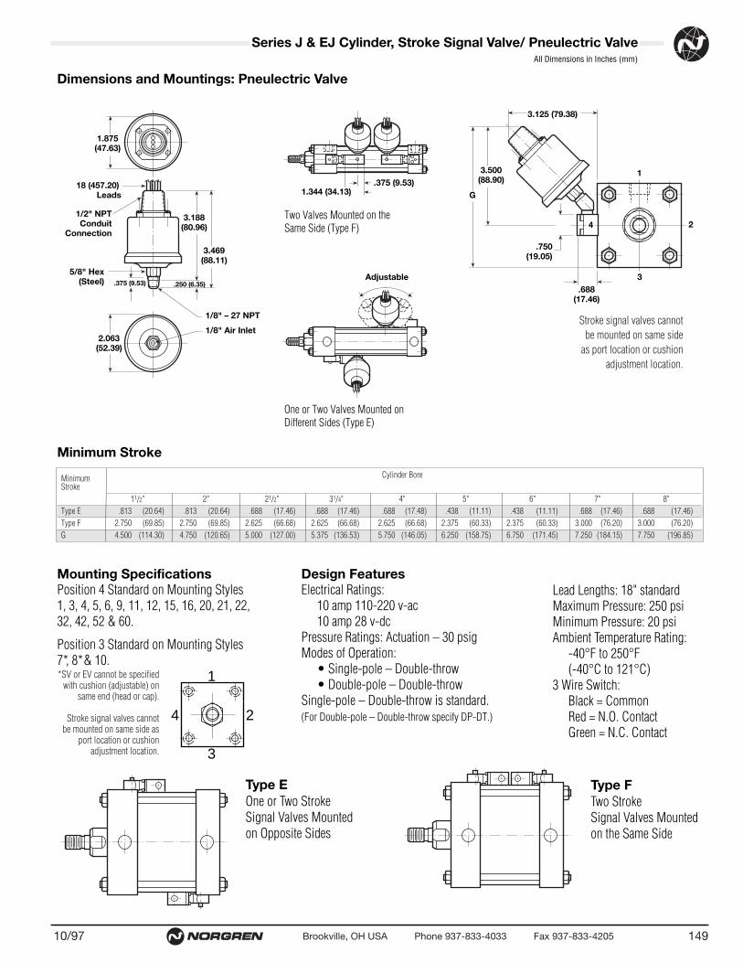
(20.64) (20.64) (17.46) (17.46) (17.48) (11.11) (11.11) (17.46) (17.46)(69.85) (69.85) (66.68) (66.68) (66.68) (60.33) (60.33) (76.20) (76.20)
(114.30) (120.65) (127.00) (136.53) (146.05) (158.75) (171.45) (184.15) (196.85)
Minimum Cylinder BoreStroke
11/2" 2" 21/2" 31/4" 4" 5" 6" 7" 8"Type E .813 .813 .688 .688 .688 .438 .438 .688 .688Type F 2.750 2.750 2.625 2.625 2.625 2.375 2.375 3.000 3.000G 4.500 4.750 5.000 5.375 5.750 6.250 6.750 7.250 7.750
14910/97 Brookville, OH USA Phone 937-833-4033 Fax 937-833-4205
Series J & EJ Cylinder, Stroke Signal Valve/ Pneulectric ValveAll Dimensions in Inches (mm)
Mounting SpecificationsPosition 4 Standard on Mounting Styles1, 3, 4, 5, 6, 9, 11, 12, 15, 16, 20, 21, 22,32, 42, 52 & 60.
Position 3 Standard on Mounting Styles 7*, 8*& 10.
Design FeaturesElectrical Ratings:
10 amp 110-220 v-ac10 amp 28 v-dc
Pressure Ratings: Actuation – 30 psigModes of Operation:
• Single-pole – Double-throw • Double-pole – Double-throw
Single-pole – Double-throw is standard. (For Double-pole – Double-throw specify DP-DT.)
Dimensions and Mountings: Pneulectric Valve
Two Valves Mounted on the Same Side (Type F)
One or Two Valves Mounted onDifferent Sides (Type E)
Lead Lengths: 18" standardMaximum Pressure: 250 psiMinimum Pressure: 20 psiAmbient Temperature Rating:
-40°F to 250°F(-40°C to 121°C)
3 Wire Switch:Black = CommonRed = N.O. ContactGreen = N.C. Contact
Minimum Stroke
Type EOne or Two StrokeSignal Valves Mountedon Opposite Sides
Type FTwo StrokeSignal Valves Mountedon the Same Side
18 (457.20)Leads
1.875(47.63)
3.188(80.96)
1.344 (34.13).375 (9.53)
3.125 (79.38)
.750(19.05)
.688(17.46)
2
1
3
4
3.500(88.90)
G
.250 (6.35).375 (9.53)
3.469(88.11)
5/8" Hex(Steel)
1/8" Air Inlet
Adjustable
1/8" – 27 NPT
2.063(52.39)
1/2" NPTConduit
Connection
1
3
4 2
*SV or EV cannot be specifiedwith cushion (adjustable) on
same end (head or cap).
Stroke signal valves cannot be mounted on same side as
port location or cushionadjustment location.
Stroke signal valves cannotbe mounted on same side
as port location or cushionadjustment location.

10/97150
• Magnetically operated, non-contact sensing system.
• Consists of a magnet in the piston, and a sensing switch clamped on the cylinder tie rod.
• One or more switches may be mounted to provide an indication of piston position or to control or initiate any sequence function.
• Adjustable mounting brackets allow for switches to be securely positioned anywhere along the range of piston travel.
• LED indicator light facilitates installation and troubleshooting.
• Mounting brackets standard with switches.
Series J & EJ Cylinder SwitchesSwitches for 1-1/2" to 2-1/2" Cylinders
Switch & Mounting Bracket Dimensions
Supply6-24 VDC
Supply6-24 VDC
Supply120V Max
0.45 0.100.10
–
–
–
+
+
+
Center of Sensing AreaCenter of Sensing AreaCenter of Sensing Area
LoadLoadLoad
BRN
WHT
WHT
WHT
BRN
BRN
GRNGRN
Specifications
Wiring Diagrams
*Metal Oxide Varsitor Surge Suppression. NOTE: All CS8 Series Switches are supplied with 9 foot leads.
CS8-2 Series
1.263".53"
1.078"
.698" .425"
Brookville, OH USA Phone 937-833-4033 Fax 937-833-4205
Switch Model CS8-2-04 Reed CS8-2-31 Solid State CS8-2-32 Solid State
Bore Sizes 11/2" thru 21/2" 11/2" thru 21/2" 11/2" thru 21/2"Switch Type Reed Switch Solid State & Light, Solid State & Light,
*MOV & Light Sourcing PNP Sinking NPNFunction SPST Normally Open Normally Open Normally OpenSwitching Voltage 5-120 VDC/VAC 6-24 VDC 6-24 VDC
50/60 HzSwitching Current .5 Amp Max .5 Amp Max .5 Amp Max
.005 Amp MinSwitching Power 10 VA 12 Watts Max 12 Watts MaxMax Voltage Drop 3.5 Volts .5 Volts .5 VoltsMagnetic Sensitivity 85 Gauss 85 Gauss 85 Gauss
Enclosure Classification NEMA 6 & CSA Approved NEMA 6 & CSA Approved NEMA 6 & CSA ApprovedTemperature Range -22°F to +176°F -22°F to +176°F -22°F to +176°F
NOTE:1-1/2" to 2-1/2" bore steel cylinder issupplied with an aluminum tube asstandard. If a 3-1/4" to 12" bore steelcylinder requires switches, the aluminumtube and magnetic piston options mustbe selected.

15110/97 Brookville, OH USA Phone 937-833-4033 Fax 937-833-4205
CS7-04 Reed CS7-24 Reed CS7-31 Solid State CS7-32 Solid State
2" thru 8" 2" thru 8" 2" thru 8" 2" thru 8"Reed Switch Reed Switch Solid State & Light, Solid State & Light,*MOV & Light *MOV & Light, 3 Wire Sourcing PNP Sinking NPNNormally Open Normally Open Normally Open Normally Open5-240 VDC/VAC 24-240 VAC 6-24 VDC 6-24 VDC50/60 Hz 50/60 Hz1 Amp Max 4 Amp Max 1 Amp Max 1 Amp Max
50 Amp Inrush30 Watts Max 100 Watts Max 24 Watts Max 24 Watts Max3 Volts N/A .5 Volts .5 Volts85 Gauss 85 Gauss 85 Gauss 85 Gauss Parallel Parallel Parallel ParallelNEMA 6 & CSA Approved NEMA 6 & CSA Approved NEMA 6 & CSA Approved NEMA 6 & CSA Approved-22°F to +176°F -22°F to +176°F -22°F to +176°F -22°F to +176°F
Switches for 2" to 12" Series J & EJ Cylinders
NOTE: For 8" bore add 9 to part number. Example: CS7-9-04. For 10" and 12" bore, consult the factory.
ACSupply
SupplyAC/DC
SupplyAC/DC
Supply6-24 VDC
–
–– +
++
LoadLoad
Load
Load
RED
RED BLK
BLK
BLK
BLKWHTWHT
WHT
RED
RED
CS7 Series
1.27"
1.40".327"
.85"
Hook Up Cable
Indicator Light
.68"
.68"
1.66"
1.28"
.86"
Reed Switch Working PrincipleReed switch sensors contain hermetically sealed reed elements(mechanical contacts) which are open in their normal state. Whena magnetic field moves within proximity of the switch, magnetismis induced into the leads and forces the contacts to close.
In order to obtain optimum performance and long life, magnetically operatedlimit switches should not be subjected to: (1) strong magnetic fields, (2) extreme temperature, and (3) excessive ferrous filing or chip buildup.
Improper wiring may damage or destroy the switch. The wiring diagram, alongwith the listed power ratings, must be carefully observed before connectingpower to the switch.
Lower power switches are designed for signaling electronic circuits. Do not useon relay loads or with incandescent bulbs. Resistive loads only.
Normally Open Reed
Magnet
SensorSensor
Supply Supply
Output Output
V<>0V=0
N
–
+
–
+
SSwitch Open
N S
Switch Closed
Normally Open Reed
Solid State/Magnetoresistive Working PrincipleThe solid state (no moving parts) magnetoresistive sensorresponds to a parallel magnetic pole by providing a digital signalto the output control circuit. This technique enables the sensing ofweak magnetic fields, with no limit to the maximum strength of themagnetic field. Norgren solid state switches are similiar to the Halleffect switch.
Application Recommendations and PrecautionsTo provide maximum reliability.1. Always stay within the specifications and power rating limitations of the
unit installed.2. Primary and control circuit wiring should not be mixed in the same conduit.
Motors will produce high pulses that will be introduced into the control wiringif the wiring is carried in the same conduit.
3. Never connect the switch without a load present. The switch will be destroyed.4. Some electrical loads may be capacitive. Capacitive loading may occur due to
distributed capacity in cable runs over 25 feet. Use switch Model CS7-24 whenever capacitive loading may occur.

● 360° rotation of the banjo body around the bolt allows for idealpositioning of tubing.
● Low profile and reduced physical size provide space savinginstallations, while internal configuration provides the flowcapacity of much bulkier designs.
● Tapered adjustment needles with large adjustment ranges provide linear flows and greater precision.
● Knurled adjustment knobs (w/screw driver slot) and lock nuts on 12 VA0 and 10 TA0 series provide finger tip adjustment. Tamperresistance on the 10 K51 is provided by a slotted adjustmentscrew covered by a protective plastic cap.
● Direct mounting of flow controls on pneumatic actuators minimizes the adjustment problems encountered due to the compressibility of air in long tubing runs between the actuator and control valving. Additionally, direct mounted flowcontrols end the confusion over which actuator in a circuit isbeing controlled.
● Metallic components are limited to nickel plated all brass construction, eliminating the potential problems encountered withproducts constructed of dissimilar metals.
● Adjustment needles and banjo bodies are retained, preventingaccidental loss of the needle or lock nut.
OperationFlow Controls are checked adjustable controls of the meter out type.Compressed air passes freely into the push-in fitting portion of the flowcontrol, flowing past the check seal and entering the connected component. In reverse flow conditions, air passes back into the flowcontrol and energizes the check seal. Air must now flow through themetered passage controlled by the tapered adjustment needle of the flowcontrol, and finally exits through the push-in fitting end.Specifications
Fluid: Compressed air. For other types of compressed gases, please consult factory.
Working Pressure: 0 to 150 psig (0 to 10 bar)Temperature Range: 0° to 175°F (-20° to 80°C)
Materials of ConstructionBanjo bolt, collet, adjustment knob and lock nut: Nickel plated brassTapered adjusting needle: BrassBanjo Body 10 TA0 and 12 VA0 XXXX: Thermoplastic
10 K51 XXXX: Nickel plated brassO-rings and check-seal: Silicone free NitrileSealing washer: Thermoplastic (ISO G and 10-32 UNF)Tubing: Nylon 11 or 12, 95 durometer polyurethane.Thread Sealant: Thread sealant is applied to the full circumference oftapered male threads.
OptionsSpecial versions of the flow controls are available, including meter-outand bi-directional control configurations. Please consult factory with specific quantities and requirements.
������
������
������
������
������
������
�����
�����
�����
��������������������
Free Flow In(Metered Flow Out)
Free Flow Out(Metered Flow In)
TaperedAdjustment Needle
Check Seal
PneumaticSymbol
10/97152 Brookville, OH USA Phone 937-833-4033 Fax 937-833-4205
Flow ControlsRight Angle (Banjo) Flow Controls
Pneumatic Symbol

G 1/2
G 3/8
0 1 2 3 4 5 6 7 8 9 10 110
10
20
30
40Flow of Air I/s
Inlet pressure 6 BAR (90 PSIG), flow to atmosphereNumber of Turns
K51 BANJO FLOW CONTROLFLOW CHARACTERISTICS
(21.0)
(42.0)
(63.6)
(84.8)
(scfm)
GSquare
D
Ø F
ØE
J
‘K’ A/F HexB
H (Closed)
L Adjustment
ØC ØA
K51 Series
15310/97 Brookville, OH USA Phone 937-833-4033 Fax 937-833-4205
Flow Controls
0.5
11.5
22.5
33.5
44.5
55.5
66.5
77.5
8(0)
(1)
(2)
(3)
(4)
(5)
(6)
(7)
(8)
(I/s)
Inlet pressure 90 psig (6 bar), flow to atmosphere
17.0
14.8
Flow of Air (scfm)
12.7
10.
8.
6.4
4.2
2
0
Number of Turns
VAO Banjo Flow ControlFlow Characteristics
(10-32, 1/8, 1/4, and 3/8 NPTF)
10-32 UNF
1/8 NPTF
1/4 NPTF
3/8 NPTF
ØSB
CA/F
E
G
L
ØD ØA
G 1/4
G 1/8
0.5
11.5
22.5
33.5
44.5
55.5
66.5
77.5
80
1
2
3
4
5
6
7
8
Flow of Air I/s
Inlet pressure 6 BAR (90 psig), flow to atmosphere
(17.0)
9(19.0)
10(21.0)
11(23.0)
(14.8)
(scfm)
(12.7)
(10.6)
(8.5)
(6.4)
(4.2)
(2.1)
(0)
Number of Turns
K51 BANJO FLOW CONTROLFLOW CHARACTERISTICS
1/2 NPTF
0 1 2 3 4 5 6 7 8 9 10 110
(10)
(20)
(30)
(40)
(I/s)
Inlet pressure 90 psig (6 bar), flow to atmoshpereNumber of Turns
21
42
63.6
84.8Flow of Air (SCFM)
VAO Banjo Flow ControlFlow Characteristics
(1/2 NPTF)
VA0 Series Dimensions in Inches (mm)
5/32"10-32 UNF 12 VA0 0210
1/8 12 VA0 0218
1/4"1/8 12 VA0 04181/4 12 VA0 0428
3/8"1/4 12 VA0 06283/8 12 VA0 0638
1/2" 1/2 12 VA0 0748
0.31 (7.87) 0.37 (9.40) 1.04 (26.41) 0.16 (4.06) 0.74 (18.80) 0.10 (2.54) – – – 0.30 (7.62) 0.45 (11.43) 0.87 (22.10) 0.31 (7.87) 0.35 (8.89) 0.63 (16.00) 2.09 (53.09) 0.89 (22.61) 9/16" 0.43 10.93) 0.51 (12.95) 0.91 (23.11) 0.31 (7.87) 0.35 (8.89) 0.63 (16.00) 2.09 (53.09) 0.89 (22.61) 9/16" 0.43 (10.93) 0.53 (13.46) 1.00 (25.4) 0.39 (9.90) 0.43 (10.93) 0.79 (20.07) 2.64 (67.06) 1.16 (29.46) 11/16" 0.57 (14.48) 0.77 (19.56) 0.24 (6.10) 0.39 (9.90) 0.43 (10.93) 0.79 (20.07) 2.64 (67.06) 1.16 (29.46) 11/16" 0.57 (14.48) 0.77 (19.56) 1.28 (32.51) 0.47 (11.94) 0.51 (12.95) 0.87 (22.09) 3.07 (77.97) 1.30 (33.02) 3/4" 0.71 (18.03) 0.91 (23.11) 1.50 (38.10) 0.63 (16.00) 0.71 (18.03) 1.06 (26.92) 3.66 (92.97) 1.65 (41.91) 7/8"
BA NPTF or
Tube UNF K LO.D. Thread Part Number C D E F G H J A/F ADJ
0.31 (7.87) 0.37 (9.40) 1.04 (26.41) 0.16 (4.06) 0.74 (18.80) 0.10 (2.54)0.55 (13.97) 0.43 (10.92) 1.34 (34.03) 0.26 (6.60) 0.81 (20.57) 0.20 (5.08)0.31 (7.87) 0.43 (10.92) 1.04 (26.41) 0.16 (4.06) 0.80 (20.32) 0.10 (2.54)0.55 (13.97) 0.45 (11.43) 1.34 (34.04) 0.26 (6.60) 0.85 (21.59) 0.20 (5.08)0.31 (7.87) 0.49 (12.45) 1.04 (26.41) 0.16 (4.06) 0.87 (22.10) 0.10 (2.54)0.55 (13.97) 0.49 (12.45) 1.34 (34.04) 0.26 (6.60) 0.93 (23.62) 0.20 (5.08)0.67 (17.01) 0.51 (12.95) 1.44 (36.57) 0.28 (7.11) 0.95 (24.13) 0.33 (8.38)0.67 (17.01) 0.55 (13.97) 1.44 (36.57) 0.28 (7.11) 0.97 (24.64) 0.33 (8.38)0.87 (22.10) 0.65 (16.51) 2.03 (51.56) 0.43 (10.92) 1.05 (26.67) 0.39 (9.90)0.87 (22.10) 0.67 (17.01) 2.03 (51.56) 0.43 (10.92) 1.23 (31.24) 0.39 (9.90)1.06 (26.92) 0.69 (17.53) 2.26 (57.40) 0.39 (9.91) 1.50 (38.10) -
4"M5 X .8 10 K51 0405
1/8 10 K51 0418
5"M5 X .8 10 K51 0505
1/8 10 K51 0518M5 X .8 10 K51 0605
6" 1/8 10 K51 06181/4 10 K51 0628
8"1/4 10 K51 08283/8 10 K51 0838
10" 3/8 10 K51 103812" 1/2 10 K51 1248
BA ISO G or
Tube Metric CO.D. Thread Part Number A/F D E G L S

(38.10) (68.25) (101.60) (142.88) (219.08)(31.75) (50.80) (63.50) (63.50) (76.20)(19.05) (101.60) (127.00) (127.00) (168.28)(19.05) (120.65) (152.40) (152.40) (203.20)
(9.53) (12.70) (12.70) (17.45)(3.18) (4.75) (4.75) (6.35)
(63.50) (95.25) (139.70) (215.90)(44.45) (69.85) (107.95) (180.98)(11.10) (14.27) (14.27) (20.62)
(3.18) (9.53) (12.70) (12.70) (19.05)(3.18) (6.35) (9.53) (9.53) (12.70)
1.500 2.687 4.000 5.625 8.6251.250 2.000 2.500 2.500 3.000.750 4.000 5.000 5.000 6.625.750 4.750 6.000 6.000 8.000
.375 .500 .500 .687
.125 .187 .187 .2502.500 3.750 5.500 8.5001.750 2.750 4.250 7.125.437 .562 .562 .812
.125 .375 .500 .500 .750
.125 .250 .375 .375 .500
10/97154 Brookville, OH USA Phone 937-833-4033 Fax 937-833-4205
Air-Oil Tank Volumes (cubic inches)
�������
�������
������
���
���
G Across Flats
øF Shank
.062Radial Float2˚ Spherical
Motion
øB
A Thds.
A Thds.
E E
DC
H AcrossFlats
Rod Alignment CouplerThe Rod Alignment Coupler allows 1/16" of radialfloat and 2° of spherical movement. This preventscylinder binding due to misalignment thus extending bearing and seal life, and permits greater tolerance between the centerline of thecylinder and mating part for simplified installation.
Air-Oil TankAvailable in 5 practical bore sizes: 11/8", 2", 31/4", 5", and 8", the Air-Oil Tank includes a translucentfiberglass tube which permits viewing of the tank oil level from any position, internal baffles thatreduce foaming and aeration of the system oilresulting in maximum cylinder control, and standard angle mounting brackets (except 11/8"bore) easily removed for convenient fluid port positioning.
How to Figure Length of VolumeThe following equations are given to help you in selecting the right air/oil tank volume for your particular application.Volume of Cylinder: • Cap End Cylinder Bore Area x Stroke = Volume
• Head End Cylinder Bore Area – (Piston Rod Area*) x Stroke = Volume *Reference Page 78 for Areas.Length of Tank = Volume of Cylinder x 1.3** (See chart below.) **30% minimum recommended reserve working volume.
Tank Bore AreaFinal Length of Volume of Tank = Working length of tank + 2" minimum safety factor to prevent aeration of oil.
Note: Length must be at least 3".
øJ (4)L NPTFill Port
K NPT Port
*C *B
D
A
K NPTPort
GH
L NPTFill
Port
F E
*D*C*B
EA
1 1/8" Bore only
*plus internal length
.995 sq." 3.14 sq." 8.30 sq." 19.64 sq." 50.26 sq."5.9 18.6 49.8 117.8 301.57.9 25.1 66.4 157.1 402.09.9 31.4 83.0 196.4 502.6
11.9 37.6 99.6 235.6 603.113.9 43.9 116.2 274.9 703.615.9 50.2 132.8 314.2 804.117.9 56.5 149.4 353.5 904.519.9 62.8 166.0 392.8 1005.2
Bore 1-1/8" 2" 3-1/4" 5" 8"Area6"8"10"12"14"16"18"20"In
tern
al L
engt
h of
Tan
k
Air-Oil Tank Dimensions
How to Order: Specify air-oil tank part number and internal length.Example: 2" bore with 6" internal length = AOT-04 x 6
Note: Maximum operating pressure 250 PSI.
All Dimensions in Inches (mm)
Bore 1-1/8" 2" 3-1/4" 5" 8"AOT-225 AOT-04 AOT-065 AOT-10 AOT-16
ABCDE –F –G –H –øJ –KL
Rod Alignment Coupler & Air-Oil Tank
(31.75) (31.75) (31.75) (44.45) (44.45) (63.50) (63.50) (82.50) (82.50)(50.80) (50.80) (50.80) (58.72) (58.72) (74.60) (74.60) (111.13) (111.13)(12.70) (12.70) (12.70) (12.70) (12.70) (12.70) (12.70) (20.62) (20.62)(19.05) (19.05) (19.05) (28.58) (28.58) (41.28) (41.28) (57.15) (57.15)(28.58) (28.58) (28.58) (24.61) (24.61) (34.93) (34.93) (44.45) (44.45)(12.70) (12.70) (12.70) (20.62) (20.62) (29.36) (29.36) (38.10) (38.10)(28.58) (28.58) (28.58) (38.10) (38.10) (57.15) (57.15) (76.20) (76.20)
1.250 1.250 1.250 1.750 1.750 2.500 2.500 3.250 3.2502.000 2.000 2.000 2.312 2.312 2.937 2.937 4.375 4.375.500 .500 .500 .500 .500 .500 .500 .812 .812.750 .750 .750 1.125 1.125 1.625 1.625 2.250 2.250.625 .625 .625 .969 .969 1.375 1.375 1.750 1.750.500 .500 .500 .812 .812 1.156 1.156 1.500 1.500
1.125 1.125 1.125 1.500 1.500 2.250 2.250 3.000 3.000
Rod Alignment Coupler DimensionsCC-1-07 CC-1-08 CC-1-10 CC-1-12 CC-1-14 CC-1-16 CC-1-20 CC-1-24 CC-1-28
A 7/16 – 20 1/2 – 20 5/8 – 18 3/4 – 16 7/8 – 14 1 – 14 11/4 – 12 11/2 – 12 13/4 – 12BCDEFGH
Max Pull (lbs.) 10,000 14,000 19,000 34,000 39,000 64,000 78,000 134,000 134,000
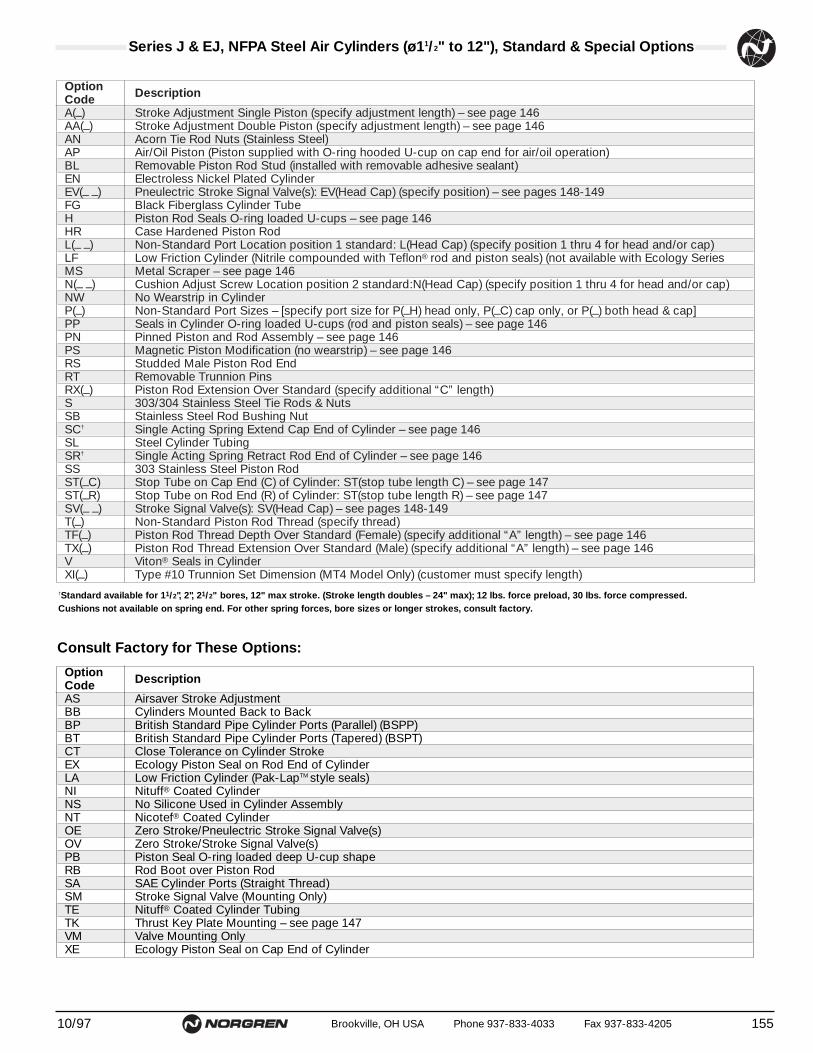
Option DescriptionCodeA(–) Stroke Adjustment Single Piston (specify adjustment length) – see page 146AA(–) Stroke Adjustment Double Piston (specify adjustment length) – see page 146AN Acorn Tie Rod Nuts (Stainless Steel)AP Air/Oil Piston (Piston supplied with O-ring hooded U-cup on cap end for air/oil operation)BL Removable Piston Rod Stud (installed with removable adhesive sealant)EN Electroless Nickel Plated CylinderEV(– –) Pneulectric Stroke Signal Valve(s): EV(Head Cap) (specify position) – see pages 148-149FG Black Fiberglass Cylinder TubeH Piston Rod Seals O-ring loaded U-cups – see page 146HR Case Hardened Piston RodL(– –) Non-Standard Port Location position 1 standard: L(Head Cap) (specify position 1 thru 4 for head and/or cap)LF Low Friction Cylinder (Nitrile compounded with Teflon® rod and piston seals) (not available with Ecology SeriesMS Metal Scraper – see page 146N(– –) Cushion Adjust Screw Location position 2 standard:N(Head Cap) (specify position 1 thru 4 for head and/or cap)NW No Wearstrip in CylinderP(–) Non-Standard Port Sizes – [specify port size for P(–H) head only, P(–C) cap only, or P(–) both head & cap]PP Seals in Cylinder O-ring loaded U-cups (rod and piston seals) – see page 146PN Pinned Piston and Rod Assembly – see page 146PS Magnetic Piston Modification (no wearstrip) – see page 146RS Studded Male Piston Rod EndRT Removable Trunnion PinsRX(–) Piston Rod Extension Over Standard (specify additional “C” length)S 303/304 Stainless Steel Tie Rods & NutsSB Stainless Steel Rod Bushing NutSC† Single Acting Spring Extend Cap End of Cylinder – see page 146SL Steel Cylinder TubingSR† Single Acting Spring Retract Rod End of Cylinder – see page 146SS 303 Stainless Steel Piston RodST(–C) Stop Tube on Cap End (C) of Cylinder: ST(stop tube length C) – see page 147ST(–R) Stop Tube on Rod End (R) of Cylinder: ST(stop tube length R) – see page 147SV(– –) Stroke Signal Valve(s): SV(Head Cap) – see pages 148-149T(–) Non-Standard Piston Rod Thread (specify thread)TF(–) Piston Rod Thread Depth Over Standard (Female) (specify additional “A” length) – see page 146TX(–) Piston Rod Thread Extension Over Standard (Male) (specify additional “A” length) – see page 146V Viton® Seals in CylinderXI(–) Type #10 Trunnion Set Dimension (MT4 Model Only) (customer must specify length)
Series J & EJ, NFPA Steel Air Cylinders (ø11/2" to 12"), Standard & Special Options
15510/97 Brookville, OH USA Phone 937-833-4033 Fax 937-833-4205
Consult Factory for These Options:
†Standard available for 11/2", 2", 21/2" bores, 12" max stroke. (Stroke length doubles – 24" max); 12 lbs. force preload, 30 lbs. force compressed. Cushions not available on spring end. For other spring forces, bore sizes or longer strokes, consult factory.
Option DescriptionCodeAS Airsaver Stroke AdjustmentBB Cylinders Mounted Back to BackBP British Standard Pipe Cylinder Ports (Parallel) (BSPP)BT British Standard Pipe Cylinder Ports (Tapered) (BSPT)CT Close Tolerance on Cylinder StrokeEX Ecology Piston Seal on Rod End of CylinderLA Low Friction Cylinder (Pak-LapTM style seals)NI Nituff® Coated CylinderNS No Silicone Used in Cylinder AssemblyNT Nicotef® Coated CylinderOE Zero Stroke/Pneulectric Stroke Signal Valve(s)OV Zero Stroke/Stroke Signal Valve(s)PB Piston Seal O-ring loaded deep U-cup shapeRB Rod Boot over Piston RodSA SAE Cylinder Ports (Straight Thread)SM Stroke Signal Valve (Mounting Only)TE Nituff® Coated Cylinder TubingTK Thrust Key Plate Mounting – see page 147VM Valve Mounting OnlyXE Ecology Piston Seal on Cap End of Cylinder

10/97156 Brookville, OH USA Phone 937-833-4033 Fax 937-833-4205
HR–L(14)–MS–P(1/4)–V
J Series J CylinderDJ Series J Double Rod End CylinderEJ Series EJ CylinderEDJ Series EJ Double Rod End Cylinder
Port and Cushion Adjustment Positions (As viewed from rod end: Port standard position 1,Cushion Adjustment standard position 2.)NOTE: A Port and a Cushion Adjustment cannot be in the same position.
1
3
4 2
IMPORTANT: Write out bore and stroke completely as shown in example.
Reed & Solid State SwitchesAvailable on all bore sizes – order separately. See pages 150 & 151 for specifications.
NOTE: Consult factory when using competitive position sensing devices.
EXAMPLE: Series EJ Cylinder – MS4 side tapped mount – Adjustable cushion in head (Position 2) – Adjustable cushion in cap (Position 2) – 5/8" piston rod diameter – Smallmale (solid) piston rod thread – Case hardened rod – Head port location at 1 – Cap portlocation at 4 – Metal rod scraper option – 1/4" special port size – Viton seals option – 2" X 6" bore and stroke.
Cylinder Order Information
01 2" X 6"7 7 1AEJ – – – –
Bore and Stroke (write out )
Mounting Options01 Side Tapped (MS4)03 Head Rectangular Flange (MF1)03 Head Square (ME3) –7" & 8" Bores04 Cap Rectangular Flange (MF2)04 Cap Square (ME4) –7" & 8" Bores05 Basic Cylinder No Mounting (MX0)06 Both Ends (4) Tie Rods Ext. (MX1)6B Both Ends (2) Tie Rods Ext. (MX4)6C Cap Tie Rods Ext. (MX2)6R Head Tie Rods Ext. (MX3)07 Head Trunnion (MT1)08 Cap Trunnion (MT2)09 Side Lugs (MS2)10 Center Trunnion (MT4)11 Side End Angles (MS1)12 Cap Fixed Clevis (MP1)15 Side End Lugs (MS7)16 Sleeve Nut Construction (Universal)20 Head Square Flange (MF5)21 Cap Square Flange (MF6)22 Detachable Cap Clevis (MP2)32 Cap Fixed Eye (MP3)42 Detachable Cap Eye (MP4)52 Spherical Bearing
Piston Rod DiametersA 5/8" Standard on 11/2", 2", 21/2"
Standard on 31/4", 4", 5"B 1"
Oversized on 11/2", 2", 21/2"Standard on 6", 7", 8"
C 13/8"Oversized on 31/4", 4", 5"Standard on 10"
D 13/4"Oversized on 6", 7", 8"Standard on 12"
E 2"Oversized on 10"
F 21/2" Oversized on 10", 12"
†Standard with EJ
†Standard with EJ
Cushion in Head 3 None5† Non-Adjustable Cushion7 Adjustable Cushion (Position 2)
Cushion in Cap 3 None5† Non-Adjustable Cushion7 Adjustable Cushion (Position 2)
Piston Rod Threads Type1 Small Male (Solid)2 Intermediate Thread Male (Solid)3 Female6 Full Thread Male (Solid)7 Plain Rod End
Additional Options – order alphabetically – More on page 155HR Case Hardened (45 Rc)L(_ _) Port Location position 1 standard: L(Head Cap)
(specify position 1 thru 4 for head and/or cap)MS Metal Rod ScraperN(_ _) Cushion Adjust Screw Location position 2 standard: N(Head
Cap) (specify position 1 thru 4 for head and/or cap)P(_)* Non-Standard Port Sizes: [specify port size for P(_H)
head only, P(_C) cap only, or P(_) both head & cap]PS Magnetic Piston – includes aluminum tube option RS Rod Stud
Type 1 (5/8" – 13/4" øRod)Type 2 (5/8" & 1" øRod)
RX Rod Extensions (specify length of additional rod extension)SC Single Acting Spring Extend (Cap End)–See page 155SR Single Acting Spring Retract (Rod End)–See page 155SS 303 Stainless Steel (Hard Chrome Plated)ST(_C) Stop Tube (Cap End) (specify stop tube length)ST(_R) Stop Tube (Rod End) (specify stop tube length) T Special Rod Threads (specify rod thread)TX Thread Extensions (specify length of thread extension)V Viton® Seals
*11/2", 2", 21/2" bore cylinders have 3/8" NPT Standard, 1/2" NPT oversize. 31/4", 4", 5" bore cylinders have 1/2" NPT Standard, 3/4" NPT oversize.This will add 1/8" to the overall cylinder length.
Series J, DJ, EJ & EDJ, NFPA Steel Air Cylinders (ø11/2" to 12"), Special Order Information
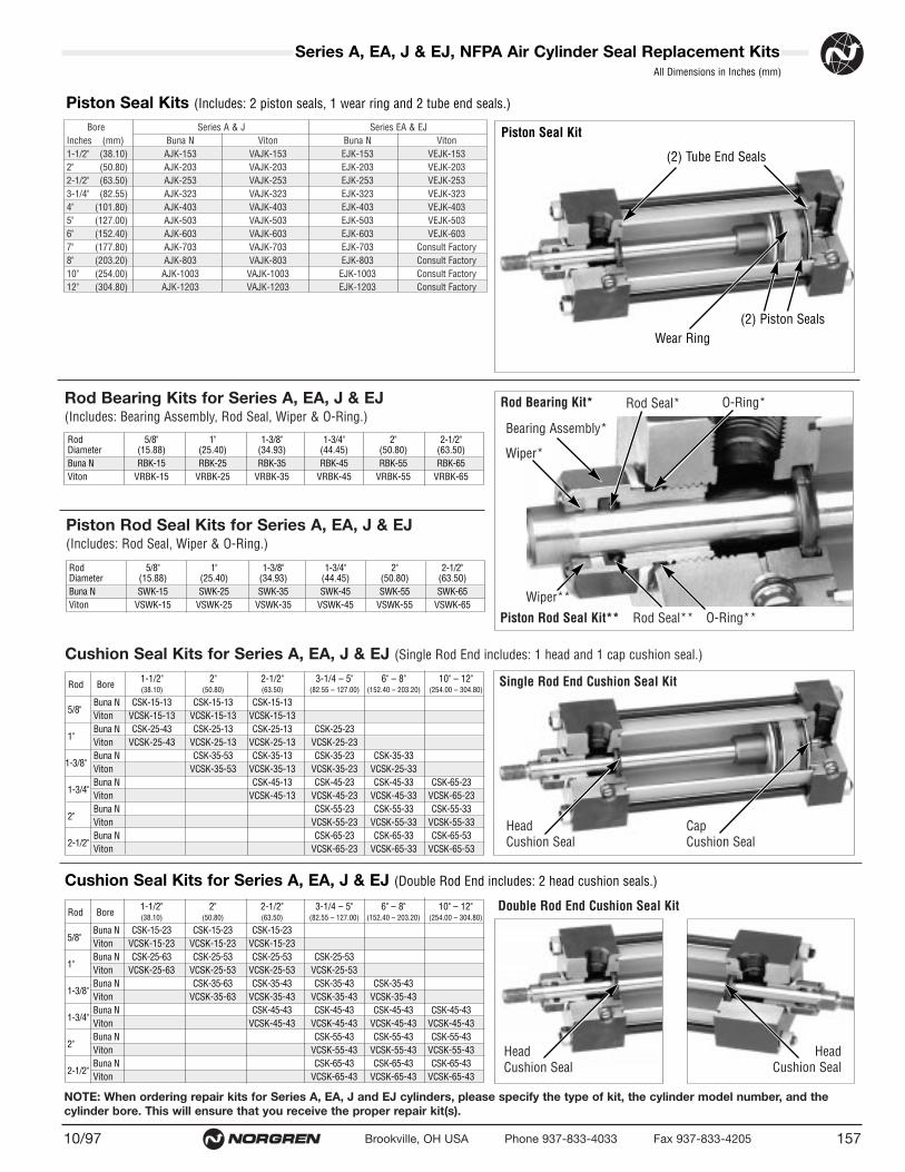
NOTE: When ordering repair kits for Series A, EA, J and EJ cylinders, please specify the type of kit, the cylinder model number, and thecylinder bore. This will ensure that you receive the proper repair kit(s).
Bore Series A & J Series EA & EJInches (mm) Buna N Viton Buna N Viton1-1/2" (38.10) AJK-153 VAJK-153 EJK-153 VEJK-1532" (50.80) AJK-203 VAJK-203 EJK-203 VEJK-2032-1/2" (63.50) AJK-253 VAJK-253 EJK-253 VEJK-2533-1/4" (82.55) AJK-323 VAJK-323 EJK-323 VEJK-3234" (101.80) AJK-403 VAJK-403 EJK-403 VEJK-4035" (127.00) AJK-503 VAJK-503 EJK-503 VEJK-5036" (152.40) AJK-603 VAJK-603 EJK-603 VEJK-6037" (177.80) AJK-703 VAJK-703 EJK-703 Consult Factory8" (203.20) AJK-803 VAJK-803 EJK-803 Consult Factory10" (254.00) AJK-1003 VAJK-1003 EJK-1003 Consult Factory12" (304.80) AJK-1203 VAJK-1203 EJK-1203 Consult Factory
15710/97 Brookville, OH USA Phone 937-833-4033 Fax 937-833-4205
Rod 5/8" 1" 1-3/8" 1-3/4" 2" 2-1/2"Diameter (15.88) (25.40) (34.93) (44.45) (50.80) (63.50)Buna N SWK-15 SWK-25 SWK-35 SWK-45 SWK-55 SWK-65Viton VSWK-15 VSWK-25 VSWK-35 VSWK-45 VSWK-55 VSWK-65
Rod 5/8" 1" 1-3/8" 1-3/4" 2" 2-1/2"Diameter (15.88) (25.40) (34.93) (44.45) (50.80) (63.50)Buna N RBK-15 RBK-25 RBK-35 RBK-45 RBK-55 RBK-65Viton VRBK-15 VRBK-25 VRBK-35 VRBK-45 VRBK-55 VRBK-65
Rod Bore1-1/2" 2" 2-1/2" 3-1/4 – 5" 6" – 8" 10" – 12"(38.10) (50.80) (63.50) (82.55 – 127.00) (152.40 – 203.20) (254.00 – 304.80)
5/8"Buna N CSK-15-13 CSK-15-13 CSK-15-13Viton VCSK-15-13 VCSK-15-13 VCSK-15-13
1"Buna N CSK-25-43 CSK-25-13 CSK-25-13 CSK-25-23Viton VCSK-25-43 VCSK-25-13 VCSK-25-13 VCSK-25-23
1-3/8"Buna N CSK-35-53 CSK-35-13 CSK-35-23 CSK-35-33Viton VCSK-35-53 VCSK-35-13 VCSK-35-23 VCSK-25-33
1-3/4"Buna N CSK-45-13 CSK-45-23 CSK-45-33 CSK-65-23Viton VCSK-45-13 VCSK-45-23 VCSK-45-33 VCSK-65-23
2"Buna N CSK-55-23 CSK-55-33 CSK-55-33Viton VCSK-55-23 VCSK-55-33 VCSK-55-33
2-1/2"Buna N CSK-65-23 CSK-65-33 CSK-65-53Viton VCSK-65-23 VCSK-65-33 VCSK-65-53
Series A, EA, J & EJ, NFPA Air Cylinder Seal Replacement KitsAll Dimensions in Inches (mm)
Piston Seal Kits (Includes: 2 piston seals, 1 wear ring and 2 tube end seals.)
Rod Bearing Kit*
Bearing Assembly*
Wiper**
Piston Rod Seal Kit**
Single Rod End Cushion Seal Kit
Wiper*
Rod Seal**
Rod Seal*
O-Ring**
Head Cushion Seal
Double Rod End Cushion Seal Kit
Head Cushion Seal
Head Cushion Seal
Cap Cushion Seal
O-Ring*Rod Bearing Kits for Series A, EA, J & EJ (Includes: Bearing Assembly, Rod Seal, Wiper & O-Ring.)
Piston Rod Seal Kits for Series A, EA, J & EJ (Includes: Rod Seal, Wiper & O-Ring.)
Cushion Seal Kits for Series A, EA, J & EJ (Single Rod End includes: 1 head and 1 cap cushion seal.)
Rod Bore1-1/2" 2" 2-1/2" 3-1/4 – 5" 6" – 8" 10" – 12"(38.10) (50.80) (63.50) (82.55 – 127.00) (152.40 – 203.20) (254.00 – 304.80)
5/8"Buna N CSK-15-23 CSK-15-23 CSK-15-23Viton VCSK-15-23 VCSK-15-23 VCSK-15-23
1"Buna N CSK-25-63 CSK-25-53 CSK-25-53 CSK-25-53Viton VCSK-25-63 VCSK-25-53 VCSK-25-53 VCSK-25-53
1-3/8"Buna N CSK-35-63 CSK-35-43 CSK-35-43 CSK-35-43Viton VCSK-35-63 VCSK-35-43 VCSK-35-43 VCSK-35-43
1-3/4"Buna N CSK-45-43 CSK-45-43 CSK-45-43 CSK-45-43Viton VCSK-45-43 VCSK-45-43 VCSK-45-43 VCSK-45-43
2"Buna N CSK-55-43 CSK-55-43 CSK-55-43Viton VCSK-55-43 VCSK-55-43 VCSK-55-43
2-1/2"Buna N CSK-65-43 CSK-65-43 CSK-65-43Viton VCSK-65-43 VCSK-65-43 VCSK-65-43
Cushion Seal Kits for Series A, EA, J & EJ (Double Rod End includes: 2 head cushion seals.)
(2) Tube End Seals
Piston Seal Kit
Wear Ring(2) Piston Seals

These products are intended for use inindustrial compressed air systems only. Donot use these products where pressuresand temperatures can exceed those listedunder Technical Information.
Before using these products with fluidsother than those specified, for nonindustrialapplications, life-support systems, or otherapplications not within published specifications, consult NORGREN.
Through misuse, age, or malfunction,components used in fluid power systemscan fail in various modes. The systemdesigner is warned to consider the failuremodes of all component parts used in fluidpower systems and to provide adequatesafeguards to prevent personal injury ordamage to equipment in the event of suchfailure modes. System designers mustprovide a warning to end users in thesystem instructional manual if protection against a failure mode cannot be adequately provided.
System designers and end users arecautioned to review specific warningsfound in instruction sheets packed andshipped with these products. Systemdesigners should also provide for all OSHA requirements including Title 29 CFR1910.147 Lockout/Tagout.
It should be recognized that warningsare valid for any product, regardless ofmanufacturer, and are not restricted toproducts manufactured by NORGREN.NORGREN’s reputation for product qualityand performance is well established. Wefeel we have the additional obligation toprovide information or warnings to customers to assist them in applying ourproducts in a reasonable and safe manner.
Limited Warranty, Disclaimer & Limitation of Remedies
Items sold by NORGREN are warrantedto be free from defects in materials andworkmanship for a period of two years from the date of manufacture, providedsaid items are used according toNORGREN’s recommended usages.NORGREN’s liability is limited to the repairof, refund of purchase price paid for, orreplacement in kind of, at NORGREN’ssole option, any items proved defective,provided the allegedly defective items arereturned to NORGREN prepaid. The warranties expressed above are in lieu ofand exclusive of all other warranties.
There are no other warranties,expressed or implied, except as stated herein. There are no impliedwarranties of merchantability or fitnessfor a particular purpose, which arespecifically disclaimed. NORGREN’s liability for breach of warranty as herein stated is the exclusive remedy,and in no event shall NORGREN beliable or responsible for incidental orconsequential damages, even if thepossibility of such incidental or consequential damages has been made known to NORGREN.
NORGREN reserves the right to discontinue manufacture of any product or change product materials, design, orspecifications without notice.
WARNING
WARRANTY
10/97Brookville, OH USA Phone 937-833-4033 Fax 937-833-4205158
Warning and Warranty