![JAXMSTR - [01 35 26.PRN] - saj.usace.army.mil · NATIONAL FIRE PROTECTION ASSOCIATION (NFPA) NFPA 10 (2013) Standard for Portable Fire Extinguishers NFPA 241 (2013) Standard for Safeguarding](https://static.fdocuments.in/doc/165x107/5c6a6bfa09d3f21a048cac11/jaxmstr-01-35-26prn-sajusacearmymil-national-fire-protection-association.jpg)
NFPA 265 - baibiao.net · NFPA 265 Standard Methods of ... National Standard on August 17, 2006....
26
NFPA 265 Standard Methods of Fire Tests for Evaluating Room Fire Growth Contribution of Textile Coverings on Full Height Panels and Walls 2007 Edition NFPA, 1 Batterymarch Park, Quincy, MA 02169-7471 An International Codes and Standards Organization Copyright National Fire Protection Association Provided by IHS under license with NFPA Not for Resale No reproduction or networking permitted without license from IHS --`,,```,,,,````-`-`,,`,,`,`,,`--- The Standard is downloaded from www.bzfxw.com Standard Sharing
Transcript of NFPA 265 - baibiao.net · NFPA 265 Standard Methods of ... National Standard on August 17, 2006....

NFPA 265
Standard Methods of Fire Tests for Evaluating
Room Fire Growth Contribution of Textile Coverings
on Full Height Panels and Walls
2007 Edition
NFPA, 1 Batterymarch Park, Quincy, MA 02169-7471 An International Codes and Standards Organization
Copyright National Fire Protection Association Provided by IHS under license with NFPA
Not for ResaleNo reproduction or networking permitted without license from IHS
--`,,```,,,,````-`-`,,`,,`,`,,`---
The Standard is downloaded from www.bzfxw.com Standard Sharing

IMPORTANT NOTICES AND DISCLAIMERS CONCERNING NFPA DOCUMENTS
NOTICE AND DISCLAIMER OF LIABILITY CONCERNING THE USE OF NFPA DOCUMENTS
NFPA codes, standards, recommended practices, and guides, of which the document contained herein is one, are de-veloped through a consensus standards development process approved by the American National Standards Institute.This process brings together volunteers representing varied viewpoints and interests to achieve consensus on fire andother safety issues. While the NFPA administers the process and establishes rules to promote fairness in the develop-ment of consensus, it does not independently test, evaluate, or verify the accuracy of any information or the soundnessof any judgments contained in its codes and standards.
The NFPA disclaims liability for any personal injury, property or other damages of any nature whatsoever, whetherspecial, indirect, consequential or compensatory, directly or indirectly resulting from the publication, use of, or relianceon this document. The NFPA also makes no guaranty or warranty as to the accuracy or completeness of any informationpublished herein.
In issuing and making this document available, the NFPA is not undertaking to render professional or other servicesfor or on behalf of any person or entity. Nor is the NFPA undertaking to perform any duty owed by any person or entityto someone else. Anyone using this document should rely on his or her own independent judgment or, as appropriate,seek the advice of a competent professional in determining the exercise of reasonable care in any given circumstances.
The NFPA has no power, nor does it undertake, to police or enforce compliance with the contents of this document.Nor does the NFPA list, certify, test or inspect products, designs, or installations for compliance with this document.Any certification or other statement of compliance with the requirements of this document shall not be attributable tothe NFPA and is solely the responsibility of the certifier or maker of the statement.
Copyright National Fire Protection Association Provided by IHS under license with NFPA
Not for ResaleNo reproduction or networking permitted without license from IHS
--`,,```,,,,````-`-`,,`,,`,`,,`---
The Standard is downloaded from www.bzfxw.com Standard Sharing
ADDITIONAL NOTICES AND DISCLAIMERS
Updating of NFPA Documents
Users of NFPA codes, standards, recommended practices, and guides should be aware thatthese documents may be superseded at any time by the issuance of new editions or may beamended from time to time through the issuance of Tentative Interim Amendments. An offi-cial NFPA document at any point in time consists of the current edition of the documenttogether with any Tentative Interim Amendments and any Errata then in effect. In order todetermine whether a given document is the current edition and whether it has been amendedthrough the issuance of Tentative Interim Amendments or corrected through the issuance ofErrata, consult appropriate NFPA publications such as the National Fire Codes® SubscriptionService, visit the NFPA website at www.nfpa.org, or contact the NFPA at the address listedbelow.
Interpretations of NFPA Documents
A statement, written or oral, that is not processed in accordance with Section 6 of the Reg-ulations Governing Committee Projects shall not be considered the official position of NFPAor any of its Committees and shall not be considered to be, nor be relied upon as, a FormalInterpretation.
Patents
The NFPA does not take any position with respect to the validity of any patent rightsasserted in connection with any items which are mentioned in or are the subject of NFPAcodes, standards, recommended practices, and guides, and the NFPA disclaims liability forthe infringement of any patent resulting from the use of or reliance on these documents.Users of these documents are expressly advised that determination of the validity of any suchpatent rights, and the risk of infringement of such rights, is entirely their own responsibility.
NFPA adheres to applicable policies of the American National Standards Institute withrespect to patents. For further information contact the NFPA at the address listed below.
Law and Regulations
Users of these documents should consult applicable federal, state, and local laws and reg-ulations. NFPA does not, by the publication of its codes, standards, recommended practices,and guides, intend to urge action that is not in compliance with applicable laws, and thesedocuments may not be construed as doing so.
Copyrights
This document is copyrighted by the NFPA. It is made available for a wide variety of bothpublic and private uses. These include both use, by reference, in laws and regulations, anduse in private self-regulation, standardization, and the promotion of safe practices andmethods. By making this document available for use and adoption by public authorities andprivate users, the NFPA does not waive any rights in copyright to this document.
Use of NFPA documents for regulatory purposes should be accomplished through adop-tion by reference. The term “adoption by reference” means the citing of title, edition, andpublishing information only. Any deletions, additions, and changes desired by the adoptingauthority should be noted separately in the adopting instrument. In order to assist NFPA infollowing the uses made of its documents, adopting authorities are requested to notify theNFPA (Attention: Secretary, Standards Council) in writing of such use. For technical assis-tance and questions concerning adoption of NFPA documents, contact NFPA at the addressbelow.
For Further Information
All questions or other communications relating to NFPA codes, standards, recommendedpractices, and guides and all requests for information on NFPA procedures governing itscodes and standards development process, including information on the procedures forrequesting Formal Interpretations, for proposing Tentative Interim Amendments, and forproposing revisions to NFPA documents during regular revision cycles, should be sent toNFPA headquarters, addressed to the attention of the Secretary, Standards Council, NFPA,1 Batterymarch Park, P.O. Box 9101, Quincy, MA 02269-9101.
For more information about NFPA, visit the NFPA website at www.nfpa.org.
Copyright National Fire Protection Association Provided by IHS under license with NFPA
Not for ResaleNo reproduction or networking permitted without license from IHS
--`,,```,,,,````-`-`,,`,,`,`,,`---
The Standard is downloaded from www.bzfxw.com Standard Sharing

CCe
2
tcAtmMrr
fTmuf
pst
D
SgkMt
265–1
Copyright National Fire Protection Association Provided by IHS under license with NFPANo reproduction or networking permitted without licens
Copyright © 2006 National Fire Protection Association. All Rights Reserved.
NFPA 265
Standard Methods of
Fire Tests for Evaluating Room Fire Growth Contribution of TextileCoverings on Full Height Panels and Walls
2007 Edition
This edition of NFPA 265, Standard Methods of Fire Tests for Evaluating Room Fire Growthontribution of Textile Coverings on Full Height Panels and Walls, was prepared by the Technicalommittee on Fire Tests. It was issued by the Standards Council on July 28, 2006, with anffective date of August 17, 2006, and supersedes all previous editions.
This edition of NFPA 265 was approved as an American National Standard on August 17,006.
Origin and Development of NFPA 265The danger of using carpet-like textile coverings on walls and ceilings is well known, and
hese coverings have been recognized as a major contributing factor in many fires. Researchonducted by the Fire Research Laboratory of the University of California at Berkeley and themerican Textile Manufacturers Institute produced a report, “Room Fire Experience of Tex-
ile Wall Coverings,” that indicated that consideration of only the flame spread rating aseasured by NFPA 255, Standard Method of Test of Surface Burning Characteristics of Buildingaterials, might not reliably predict the fire behavior of textile wall coverings. Concerns were
aised regarding the findings that low flame spread textile wall coverings, when placed in aoom/corner test procedure, produced a large, rapidly growing fire.
The proposed standard was intended to fill a void and complement the series of interiorinish fire tests that were being referenced in NFPA 101®, Life Safety Code®, and other codes.he standard created a testing method that addressed the recognized hazards of using textileaterials for wall coverings by supplying a means to evaluate the performance characteristics
nder specified fire exposure conditions and providing a valid repeatable and reproducibleire test method.
The 1998 edition was revised to recognize and incorporate into the standard the currentractices being performed in testing laboratories, and requirement for the measurement ofmoke obscuration was added. These changes were directly associated with the revisions tohe 1997 edition of NFPA 101, Life Safety Code, on interior finishes.
The 2002 edition was revised to comply with the Manual of Style for NFPA Technical Committeeocuments regarding standardization of format.
The 2007 edition has been revised to include new requirements for visual documentation.pecific protocols and other related requirements have been added for video and photo-raphic equipment. Revisions also have been made to the test procedure, and what wasnown as the Method A Test Protocol in previous editions has been moved to Annex C.ethod A is a screening protocol and was deemed not to be equivalent to Method B, which
ests three fully lined walls.
--`,,```,,,,````-`-`,,`,,`,`,,`---
Not for Resalee from IHS The Standard is downloaded from www.bzfxw.com Standard Sharing

265–2 FIRE TESTS FOR EVALUATING ROOM FIRE GROWTH CONTRIBUTION OF TEXTILE COVERINGS
20
Copyright National Fire ProtProvided by IHS under licenNo reproduction or networki
Technical Committee on Fire Tests
William E. Fitch, Chair
Phyrefish Enterprises, Incorporated, FL [SE]Barry L. Badders, Jr., Southwest Research Institute,TX [RT]Jesse J. Beitel, Hughes Associates, Incorporated, MD [SE]April L. Berkol, Starwood Hotels & Resorts Worldwide,Incorporated, NY [U]
Rep. American Hotel & Lodging AssociationRobert G. Bill, Jr., FM Global, MA [I]John A. Blair, The DuPont Company, DE [M]
Rep. Society of the Plastics Industry, IncorporatedGordon H. Damant, Inter-City Testing & ConsultingCorporation of California, CA [SE]Thomas W. Fritz, Armstrong World Industries,Incorporated, PA [M]Pravinray D. Gandhi, Underwriters LaboratoriesIncorporated, IL [RT]Gordon E. Hartzell, Hartzell Consulting, Incorporated,TX [SE]Marcelo M. Hirschler, GBH International, CA [SE]Alfred J. Hogan, Reedy Creek Improvement District,FL [E]
Rep. International Fire Marshals Association
Alternates
(Alt. to T. W. Fritz)
Nonvoting
Rep. American Fiber Manufacturers Association
Milosh T. Puchovsky, NFPA Staff Liaison
Tc
Na
Cdmoat
07 Edition
ection Association se with NFPA
Not for Rng permitted without license from IHS
William E. Koffel, Koffel Associates, Incorporated,MD [SE]James R. Lawson, U.S. National Institute of Standardsand Technology, MD [RT]Rodney A. McPhee, Canadian Wood Council, Canada [M]Frederick W. Mowrer, University of Maryland, MD [SE]David T. Sheppard, U.S. Department of Justice, MD [RT]Kuma Sumathipala, American Forest & PaperAssociation, DC [M]T. Hugh Talley, Hugh Talley Company, TN [M]
Rep. Upholstered Furniture Action CouncilRick Thornberry, The Code Consortium, Incorporated,CA [SE]William A. Webb, Schirmer Engineering Corporation,IL [I]Robert A. Wessel, Gypsum Association, DC [M]Robert J. Wills, American Iron and Steel Institute,AL [M]
-`,,`,,`,`,,`---
Robert M. Berhinig, Underwriters LaboratoriesIncorporated, IL [RT]
(Alt. to P. D. Gandhi)Delbert F. Boring, Jr., American Iron and Steel Institute,OH [M]
(Alt. to R. J. Wills)Richard J. Davis, FM Global, MA [I]
(Alt. to R. G. Bill, Jr.)Sam W. Francis, American Forest & Paper Association,PA [M]
(Alt. to K. Sumathipala)Richard G. Gann, U.S. National Institute of Standardsand Technology, MD [RT]
(Alt. to J. R. Lawson)Paul A. Hough, Armstrong World Industries,Incorporated, PA [M]
Marc L. Janssens, Southwest Research Institute, TX [RT](Alt. to B. L. Badders, Jr.)
James K. Lathrop, Koffel Associates, Incorporated,CT [SE]
(Alt. to W. E. Koffel)James A. Milke, University of Maryland, MD [SE]
(Alt. to F. W. Mowrer)Arthur J. Parker, Hughes Associates, Incorporated,MD [SE]
(Alt. to J. J. Beitel)Ineke Van Zeeland, Canadian Wood Council, Canada [M]
(Alt. to R. A. McPhee)Joe Ziolkowski, American Furniture ManufacturersAssociation, NC [M]
(Alt. to T. H Talley)
,,,,````-`
--`,,```
Robert H. Barker, American Fiber ManufacturersAssociation, VA [M]
Rohit Khanna, U.S. Consumer Product SafetyCommission, MD [C]
his list represents the membership at the time the Committee was balloted on the final text of this edition. Since that time,hanges in the membership may have occurred. A key to classifications is found at the back of the document.
OTE: Membership on a committee shall not in and of itself constitute an endorsement of the Association orny document developed by the committee on which the member serves.
ommittee Scope: This Committee shall have primary responsibility for documents on fire testing proce-ures, for reviewing existing fire test standards and recommending appropriate action to NFPA, for recom-ending the application of and advising on the interpretation of acceptable test standards for fire problems
f concern to NFPA technical committees and members, and for acting in a liaison capacity between NFPAnd the committees of other organizations writing fire test standards. This Committee does not cover fireests that are used to evaluate extinguishing agents, devices, or systems.
esale The Standard is downloaded from www.bzfxw.com Standard Sharing
265–3CONTENTS
Copyright National FirProvided by IHS undeNo reproduction or ne
Contents
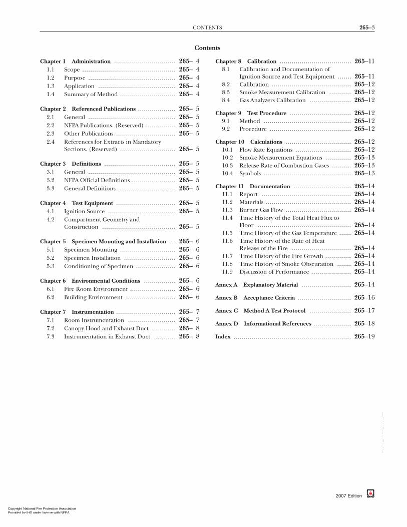
Chapter 1 Administration ............................... 265– 41.1 Scope ............................................... 265– 41.2 Purpose ............................................ 265– 41.3 Application ....................................... 265– 41.4 Summary of Method ............................ 265– 4
Chapter 2 Referenced Publications ................... 265– 52.1 General ............................................ 265– 52.2 NFPA Publications. (Reserved) ............... 265– 52.3 Other Publications .............................. 265– 52.4 References for Extracts in Mandatory
Sections. (Reserved) ............................ 265– 5
Chapter 3 Definitions .................................... 265– 53.1 General ............................................ 265– 53.2 NFPA Official Definitions ...................... 265– 53.3 General Definitions ............................. 265– 5
Chapter 4 Test Equipment .............................. 265– 54.1 Ignition Source .................................. 265– 54.2 Compartment Geometry and
Construction ..................................... 265– 5
Chapter 5 Specimen Mounting and Installation ... 265– 65.1 Specimen Mounting ............................ 265– 65.2 Specimen Installation .......................... 265– 65.3 Conditioning of Specimen .................... 265– 6
Chapter 6 Environmental Conditions ................ 265– 66.1 Fire Room Environment ....................... 265– 66.2 Building Environment ......................... 265– 6
Chapter 7 Instrumentation .............................. 265– 77.1 Room Instrumentation ........................ 265– 77.2 Canopy Hood and Exhaust Duct ............ 265– 87.3 Instrumentation in Exhaust Duct ........... 265– 8
e Protection Association r license with NFPA
Not for Rtworking permitted without license from IHS
Chapter 8 Calibration .................................... 265–118.1 Calibration and Documentation of
Ignition Source and Test Equipment ....... 265–118.2 Calibration ........................................ 265–128.3 Smoke Measurement Calibration ........... 265–128.4 Gas Analyzers Calibration ..................... 265–12
Chapter 9 Test Procedure ............................... 265–129.1 Method ............................................ 265–129.2 Procedure ......................................... 265–12
Chapter 10 Calculations ................................. 265–1210.1 Flow Rate Equations ............................ 265–1210.2 Smoke Measurement Equations ............. 265–1310.3 Release Rate of Combustion Gases .......... 265–1310.4 Symbols ............................................ 265–13
Chapter 11 Documentation ............................. 265–1411.1 Report ............................................. 265–1411.2 Materials ........................................... 265–1411.3 Burner Gas Flow ................................. 265–1411.4 Time History of the Total Heat Flux to
Floor ............................................... 265–1411.5 Time History of the Gas Temperature ...... 265–1411.6 Time History of the Rate of Heat
Release of the Fire .............................. 265–1411.7 Time History of the Fire Growth ............. 265–1411.8 Time History of Smoke Obscuration ....... 265–1411.9 Discussion of Performance .................... 265–14
Annex A Explanatory Material ......................... 265–14
Annex B Acceptance Criteria ........................... 265–16
Annex C Method A Test Protocol ..................... 265–17
Annex D Informational References ................... 265–18
Index ........................................................... 265–19
2007 Edition
esale
--`,,```,,,,````-`-`,,`,,`,`,,`---
The Standard is downloaded from www.bzfxw.com Standard Sharing

265–4 FIRE TESTS FOR EVALUATING ROOM FIRE GROWTH CONTRIBUTION OF TEXTILE COVERINGS
Copyright NationProvided by IHS No reproduction o
--`,,```,,,,````-`-`,,`,,`,`,,`---
NFPA 265
Standard Methods of
Fire Tests for Evaluating Room Fire GrowthContribution of Textile Coverings on Full
Height Panels and Walls
2007 Edition
IMPORTANT NOTE: This NFPA document is made available foruse subject to important notices and legal disclaimers. These noticesand disclaimers appear in all publications containing this documentand may be found under the heading “Important Notices and Dis-claimers Concerning NFPA Documents.” They can also be obtainedon request from NFPA or viewed at www.nfpa.org/disclaimers.
NOTICE: An asterisk (*) following the number or letterdesignating a paragraph indicates that explanatory materialon the paragraph can be found in Annex A.
Changes other than editorial are indicated by a verticalrule beside the paragraph, table, or figure in which thechange occurred. These rules are included as an aid to theuser in identifying changes from the previous edition. Whereone or more complete paragraphs have been deleted, the de-letion is indicated by a bullet (•) between the paragraphs thatremain.
Information on referenced publications can be found inChapter 2 and Annex D.
Chapter 1 Administration
1.1 Scope.
1.1.1 This standard describes a test method for determiningthe contribution of textile wall coverings to room fire growthduring specified fire exposure conditions.
1.1.2* This test method shall be used to evaluate the flamma-bility characteristics of textile wall coverings where such mate-rials constitute the exposed interior surfaces of buildings anddemountable, relocatable, full-height partitions used in openbuilding interiors.
1.1.3 This test method shall not be used to evaluate the fireendurance of assemblies, nor shall it be used to evaluate theeffect of fires originating within a wall assembly.
1.1.4 The test method shall not be used for the evaluation offloor or ceiling finishes.
1.1.5* This test method shall not apply to fabric-covered,lower-than-ceiling-height, freestanding, prefabricated panelfurniture systems.
1.2 Purpose.
1.2.1 This test method shall measure certain fire perfor-mance characteristics of textile wall covering materials in anenclosure under specified fire exposure conditions.
1.2.2 This test method shall determine the potential extentto which the textile wall covering materials contribute to firegrowth in a room and the potential for fire spread beyond theroom under the particular conditions simulated.
2007 Edition
al Fire Protection Association under license with NFPA
Nor networking permitted without license from IHS
1.3 Application.
1.3.1 This test method shall provide all of the following:
(1) Extent of fire growth in the test room(2) Rate of heat release by the specimen(3) Total heat released by the specimen(4) Time to flashover in the test room, if it occurs(5) Time to flame extension beyond the doorway of the test
room, if it occurs(6) Total heat flux incident to the floor of the test room(7) Upper level gas temperature in the test room(8) Smoke obscuration, as determined in the exhaust duct(9) Production of carbon monoxide, as determined in the
exhaust duct(10) Emissions of other combustion gases, as determined in
the exhaust duct
1.3.2 This test method shall not provide data that can begeneralized to apply to rooms or spaces of different shapes,sizes, and ventilation. However, this test method shall providea general ranking of wall covering materials for use in makingjudgments, provided it is understood that the conditions ob-served in the test might or might not be repeated in actualexposures of the tested wall coverings to fire.
1.3.3 This test method shall not provide either of the following:
(1) The full information concerning toxicity of combustiongases
(2) Fire resistance of wall–ceiling systems
1.4* Summary of Method.
1.4.1 The sample shall be tested by using a corner test expo-sure with the specimens mounted on three fully lined walls ofthe test compartment (Method B).
1.4.1.1 These test methods shall use a gas burner to producea diffusion flame to expose the walls in the corner of a room2.4 m × 3.7 m × 2.4 m (8 ft × 12 ft × 8 ft).
1.4.1.2 The burner shall produce a prescribed rate of heat out-put of 40 kW for 5 minutes followed by 150 kW for 10 minutes, fora total exposure period of 15 minutes.
1.4.1.3 The contribution of the textile wall covering to firegrowth shall be measured by constant monitoring of the inci-dent heat flux on the center of the floor, the temperature ofthe gases in the upper part of the room, the rate of heat re-lease, the smoke release, and the time to flashover.
1.4.1.4 The test shall be conducted while providing natural ven-tilation to the room, through a single doorway of 0.8 m × 2.0 m(30 in. × 80 in.).
1.4.1.5 The combustion products shall be collected in a hoodfeeding into a chamber that is connected to an exhaust duct inwhich measurements of the gas velocity, temperature, andconcentrations of selected gases are made.
1.4.2 Flashover shall be considered to have occurred whenany two of the following conditions have been attained:
(1) The heat release rate exceeds 1 MW.(2) The heat flux at floor exceeds 20 kW/m2.(3) The average upper layer temperature exceeds 600°C
(1112°F).(4) Flames exit the doorway.(5) Autoignition of paper target on floor occurs.
t for Resale The Standard is downloaded from www.bzfxw.com Standard Sharing

265–5TEST EQUIPMENT
Copyright National FirProvided by IHS undeNo reproduction or ne
Chapter 2 Referenced Publications
2.1 General. The documents or portions thereof listed in thischapter are referenced within this standard and shall be con-sidered part of the requirements of this document.
2.2 NFPA Publications. (Reserved)
2.3 Other Publications.Merriam-Webster’s Collegiate Dictionary, 11th edition, Merriam-
Webster, Inc., Springfield, MA, 2003.
2.4 References for Extracts in Mandatory Sections. (Reserved)
Chapter 3 Definitions
3.1 General. The definitions contained in this chapter shallapply to the terms used in this standard. Where terms are notdefined in this chapter or within another chapter, they shallbe defined using their ordinarily accepted meanings withinthe context in which they are used. Merriam-Webster’s CollegiateDictionary, 11th edition, shall be the source for the ordinarilyaccepted meaning.
3.2 NFPA Official Definitions.
3.2.1 Shall. Indicates a mandatory requirement.
3.2.2 Should. Indicates a recommendation or that which isadvised but not required.
3.2.3 Standard. A document, the main text of which containsonly mandatory provisions using the word “shall” to indicaterequirements and which is in a form generally suitable formandatory reference by another standard or code or for adop-tion into law. Nonmandatory provisions shall be located in anappendix or annex, footnote, or fine-print note and are not tobe considered a part of the requirements of a standard.
3.3 General Definitions.
3.3.1 Average Upper Gas Layer Temperature. Temperaturebased on the average of the four ceiling quadrant thermo-couples and the center of the room ceiling thermocouple.
3.3.2* Textile. As used in this document, originally a wovenfabric, now generally applied to (1) staple fibers and filamentssuitable for conversion to or use as yarns or for the prepara-tion of nonwoven fabrics, (2) yarns made from natural ormanufactured fibers, and (3) fabrics made from fibers as de-fined in (1) and (2) and from yarns.
Chapter 4 Test Equipment
4.1 Ignition Source.
4.1.1 The ignition source for the test shall be a gas burnerwith a nominal 305 mm × 305 mm (12 in. × 12 in.) porous topsurface of refractory material as shown in Figure 4.1.1.
4.1.2 The refractory material, through which the gas is sup-plied, shall be permitted to be either of the following:
(1) A 25.4 mm (1 in.) thick porous ceramic fiberboard over a152 mm (6 in.) chamber
(2) A layer of white Ottawa silica sand not less than 102 mm(4 in.) for providing the horizontal surface throughwhich the gas is supplied
--`,,```,,,,````-`-`,,`,,`,`,,`---
e Protection Association r license with NFPA
Not for Rtworking permitted without license from IHS
4.1.3 The top surface of the burner, through which the gas isapplied, shall be located horizontally 305 mm (12 in.) abovethe floor.
4.1.4 The burner enclosure shall be located such that theedge of the diffusion surface is located 51 mm (2 in.) fromboth walls, in a corner of the room, opposite the door.
4.1.5 The gas supply to the burner shall be of C.P. gradepropane (99 percent purity or better).
4.1.5.1 The burner shall be capable of producing a net heatoutput of 40 kW ± 1 kW for 5 minutes followed by a net heatoutput of 150 kW ± 5 kW for 10 minutes.
4.1.5.2* Flow rates shall be calculated using the net heat ofcombustion of propane or 85 MJ/m3 (2280 Btu/ft3) at stan-dard conditions of 20°C (68°F) temperature and 100 kPa(14.70 psi) absolute pressure.
4.1.5.3 The gas flow rate shall be metered throughout the testwith an accuracy of ±3 percent.
4.1.6* The heat output from the burner shall be controlled to±5 percent.
4.1.7 The burner design shall allow switching from 40 kW to150 kW within 10 seconds.
4.1.8 The burner shall be ignited by a pilot burner or a re-motely controlled spark igniter.
4.1.9 Burner controls shall be provided for automatic gassupply shutoff if flameout occurs.
4.2 Compartment Geometry and Construction. Compartmentgeometry and construction shall be as shown in Figure 4.2.
305 mm (12 in.)
305
mm
(12
in.)
152 mm (6 in.)
152
mm
(6
in.) 76 mm (3 in.)
Gas
White Ottawa silica sand
White Ottawa silica sand
Nominal 19 mm(0.75 in.) pipe
Gas
28 mm (1.125 in.)
152
mm
(6
in.)
AA
TOP VIEW
SIDE VIEW A–A
FIGURE 4.1.1 Gas Burner.
2007 Edition
esale The Standard is downloaded from www.bzfxw.com Standard Sharing

265–6 FIRE TESTS FOR EVALUATING ROOM FIRE GROWTH CONTRIBUTION OF TEXTILE COVERINGS
•
Copyright NationProvided by IHS No reproduction o
4.2.1* The interior dimensions of the fire room floor, when thespecimens are in place shall measure 2.44 m ± 0.1 m × 3.66 m± 0.1 m (8 ft ± 3.9 in. × 12 ft ± 3.9 in.).
4.2.2 The finished ceiling shall be 2.44 m ± 0.1 m (8 ft ± 3.9 in.)above the floor.
4.2.3 There shall be four walls at right angles defining thecompartment, as shown in Figure 4.2.
4.2.4* The room shall be placed indoors in an essentiallydraft-free, heated space large enough to ensure that there isno influence of the surroundings on the test fire.
4.2.5 There shall be a doorway measuring 0.76 m ± 6.4 mm× 2.03 m ± 6.4 mm (30 in. ± 0.25 in. × 80 in. ± 0.25 in.) in thecenter of one of the 2.44 m × 2.44 m (8 ft × 8 ft) walls, and noother wall, floor, or ceiling openings that allow ventilation.
4.2.6* The test compartment shall be a framed (with wood ormetal studs) or a concrete block structure.
4.2.6.1 The inside surface of the walls, ceiling, and floor shallbe of Type X gypsum wallboard or of calcium silicate board of736 kg/m3 (46 lb/ft3) density.
4.2.6.2 The nominal thickness of the inside surface shall be atleast 12 mm (0.5 in.).
4.2.6.3 For each test, when the test is for wall systems only, a newsection of uncoated and unpainted nominal 16 mm (5⁄8 in.) gyp-sum wallboard, nominal 610 mm × 610 mm (2 ft × 2 ft), shall beinstalled in the ceiling at the wall corner intersection directlyabove the burner.
4.2.7 The door frame shall be constructed to remain un-changed during the test period to a tolerance of ±1 percent inheight and width.
Chapter 5 Specimen Mounting and Installation
5.1 Specimen Mounting.
5.1.1 Test specimens shall be mounted on a substrate that isappropriate to the intended application.
3.66 m ± 0.1 m(12 ft ± 3.9 in.)
2.44 m ± 0.1 m(8 ft ± 3.9 in.)
2.03
m ±
6.4
mm
(80
in. ±
0.2
5 in
.)
2.44
m ±
0.1
m(8
ft ±
3.9
in.)
0.76 m ± 6.4 mm(30 in. ± 0.25 in.)
FIGURE 4.2 Interior Room Dimensions and Interior Door-way Dimensions.
2007 Edition
al Fire Protection Association under license with NFPA
Nor networking permitted without license from IHS
--`,,```,,,,````-`-`,,`,,`,`,,`---
5.1.2* Where a manufacturer specifies use of an adhesive,specimens shall be mounted in a manner that uses the adhe-sive and application rate specified by the manufacturer andthat is comparable to actual field installations.
5.1.3 Where a specimen exhibits a distinct direction, thesample shall be mounted such that the machine direction isvertical, unless the manufacturer indicates that a differentmethod of mounting is to be used in actual installations.
5.2 Specimen Installation. The specimen assembly shall be in-stalled on the interior wall surfaces of the test room as de-scribed in 5.2.1.
5.2.1 Method B Test Protocol. For the Method B test protocol,specimen assemblies shall be installed to cover fully both 2.44 m× 3.66 m (8 ft × 12 ft) walls and the 2.44 m × 2.44 m (8 ft × 8 ft) wallnot having the door.
5.3 Conditioning of Specimen.
5.3.1* Prior to testing, the mounted specimen shall be condi-tioned to equilibrium, as defined in 5.3.2, in an atmosphere ata temperature of 21°C ± 3°C (70°F ± 5°F) and a relative hu-midity of 50 percent ± 5 percent.
5.3.2 Equilibrium shall be considered to have been reachedwhen a representative piece of the specimen has achieved con-stant mass, which is reached when two successive weighing opera-tions, carried out at an interval of 24 hours, do not differ by morethan 0.1 percent of the mass of the test piece, or 0.1 g (0.0035 oz),whichever is greater.
5.3.3 The specimens shall be tested as soon as possible afterremoval from such conditions, if test room conditions differfrom those in 5.3.1 and 5.3.2.
5.3.4 The time between removal from conditioning roomand start of testing shall be recorded as part of the test docu-mentation.
Chapter 6 Environmental Conditions
6.1 Fire Room Environment.
6.1.1 The test building in which the fire room is located shallhave vents for the discharge of combustion products and shallhave provisions for fresh air intake, so that no oxygen-deficient air is introduced into the fire room during the test.
6.1.2 Prior to the start of the test, the ambient air at themid-height entrance to the compartment shall have a velocityof less than 0.5 m/s (100 ft/min) in any direction, as mea-sured at a horizontal distance of 0.91 m (3 ft) from the centerof the doorway.
6.1.3 The following two ambient conditions shall be main-tained:
(1) The ambient temperature in the fire room, measured byone of the thermocouples in 7.1.2, shall be in the range of18°C to 24°C (64°F to 75°F).
(2) The ambient relative humidity in the fire room shall be50 percent ± 5 percent.
6.2 Building Environment.
6.2.1 The building shall be sized so that there is no smokeaccumulation in the building below the level of the top of thefire compartment.
t for Resale The Standard is downloaded from www.bzfxw.com Standard Sharing

265–7INSTRUMENTATION
Copyright National FirProvided by IHS undeNo reproduction or ne
--`,,```,,,,````-`-`,,`,,`,`,,`---
6.2.2 The ambient temperature in the test building at loca-tions around the fire compartment shall be above 4°C (40°F).
6.2.3 The relative humidity shall be less than 75 percent forthe duration of the test.
Chapter 7 Instrumentation
7.1 Room Instrumentation. The instrumentation specified in7.1.1 through 7.1.2 shall be provided for this test.
7.1.1* Heat Flux. A total heat flux gauge (calorimeter) shall bemounted at a height of 26 mm ± 25 mm (1.1 in. ± 0.9 in.) abovethe floor surface, facing upward, in the geometric center of thetest room as shown in Figure 7.1.1.
7.1.1.1* The gauge shall be of the Gardon (foil) or Schmidt–Boelter (thermopile) type with a full-scale design range of50 kW/m2.
7.1.1.1.1 The target receiving radiation shall be a circular, flatsurface not more than 15 mm (0.4 in) in diameter and coatedwith a matte black finish, having a view angle of 180 degrees.
7.1.1.1.2 The target shall be contained within a water-cooledbody whose front face shall be of polished metal that is flat,coinciding with the plane of the target, and circular, with adiameter of not more than 50 mm (2 in.).
7.1.1.2 The heat flux gauge shall have an accuracy of ±3 per-cent and a repeatability of 0.5 percent.
7.1.1.3 During operation, the heat flux gauge shall be main-tained at a constant temperature [±3°C (±5°F)] above the dewpoint by water supplied at a temperature of 50°C to 65°C(122°F to 149°F).
= Thermocouples − each 102 mm (4 in.) below ceiling, with one additional thermocouple over the burner and 102 mm (4 in.) below the ceiling.
= Calorimeter on floor − 26 mm ± 25 mm (1.1 in. ± 0.9 in.) above floor.
3.66 m ± 0.1 m(12 ft ± 3.9 in.)
2.44 m ± 0.1 m(8 ft ± 3.9 in.)
2.44
m ±
0.1
m(8
ft ±
3.9
in.)
FIGURE 7.1.1 Thermocouple and Calorimeter Placement.
e Protection Association r license with NFPA
Not for Rtworking permitted without license from IHS
7.1.1.4 The calibration of the heat flux gauge shall bechecked, whenever required, by comparing the calibrationwith two similar instruments held as, and used exclusively as,reference standards, one of which is to be fully calibrated atyearly intervals.
7.1.2 Thermocouples. Bare Type K Chromel Alumel® ther-mocouples, 0.5 mm (20 mil) in diameter, shall be used at eachrequired location as shown in Figure 7.1.1.
7.1.2.1 The thermocouple wire within 13 mm (0.5 in.) of thebead shall be run along expected isotherms to minimize con-duction errors.
7.1.2.2* The insulation between the Chromel and Alumelwires shall be stable to a temperature not less than 1100°C(2000°F), or the wires shall be separated.
7.1.2.3 A thermocouple shall be located in the interior planeof the door opening on the door centerline, 102 mm (4 in.)from the top.
7.1.2.4 Thermocouples shall be located at six positions,102 mm (4 in.) below the ceiling.
7.1.2.4.1 These thermocouples shall be located at the centerof the ceiling, at the center of each of the four ceiling quad-rants, and directly over the center of the ignition burner.
7.1.2.4.2 The thermocouples shall be mounted on supportsor shall penetrate through the ceiling with their junctions102 mm (4 in.) away from a solid surface.
7.1.2.4.3 There shall be no attachments to the test specimens.
7.1.2.4.4 Any ceiling penetration shall be just large enoughto permit passage of the thermocouples.
7.1.2.4.5 Spackling compound or ceramic fiber insulation shallbe used to backfill the holes around the thermocouple wire.
7.1.3 Paper Targets. Two paper target flashover indicatorsconsisting of a single piece of newsprint crumpled into anapproximate 152 mm (6 in.) diameter ball shall be placed onthe floor of the test room as shown in Figure 7.1.3.
7.1.4* Video and Photographic Equipment and RecordingProcedures. Video and photographic equipment shall be usedto record the spread of fire and generation of smoke in thefire test room and the fire projection from the door of the firetest room as indicated in 7.1.4.1 through 7.1.4.4.2.
7.1.4.1 Location and Level of Lighting in Test Room. A nomi-nal 300 watt, flood-type, quartz halogen lamp shall be posi-tioned in the corner diametrically opposite the burner, nearthe floor level, and shall be aimed at the wall corner/ceilingintersection above the burner.
7.1.4.2 Wall Markings. The interior wall surfaces of the firetest room adjacent to the corner in which the burner is locatedshall be clearly marked with a 0.3 m (12 in.) grid.
7.1.4.3 Video Recording. A video camera with a manually ad-justable iris, adjusted to prevent automatic closing of this irisopening due to brightness of the fire (at least 50 percentopen), shall be used.
7.1.4.3.1 A video monitor shall be used to determine whenadjustments and compensation for the brightness of the igni-tion flames are needed.
2007 Edition
esale The Standard is downloaded from www.bzfxw.com Standard Sharing

265–8 FIRE TESTS FOR EVALUATING ROOM FIRE GROWTH CONTRIBUTION OF TEXTILE COVERINGS
•
Copyright NationProvided by IHS No reproduction o
7.1.4.3.2 The camera mount shall be adjusted so that thecamera lens is approximately 900 mm (3 ft) from the floor.
7.1.4.3.3 The camera angle and magnifications shall be ad-justed until the top of the doorway and the top of the burner arevisible and the ceiling area directly above the fire is in full view.
7.1.4.3.4 A timer depicting “elapsed time” shall be includedin all videos. The timer shall be clearly viewed throughout thetest period. The timer shall be permitted to be integral to thevideo camera.
7.1.4.3.5 Prior to ignition of the burner, the date and labora-tory test report identification number shall be filmed. Thevideo shall be started at least 30 seconds prior to ignition ofthe burner and the video recording shall be continuous forthe duration of the test period.
7.1.4.4 Photographic Documentation. A photographic record(still pictures) of the test shall be made.
7.1.4.4.1 A timer depicting “elapsed time” shall be includedin all photographs. The timer shall be clearly viewed through-out the test period. The timer shall be permitted to be integralto the camera.
7.1.4.4.2 Prior to ignition of the burner, the date and labora-tory test report identification number shall be filmed. Colorslides, photographs, or digital images shall be taken at inter-vals not exceeding 15 seconds for the first 3 minutes of the testand at intervals not exceeding 30 seconds thereafter for theduration of the test.
7.2 Canopy Hood and Exhaust Duct.
7.2.1 A hood shall be installed immediately adjacent to thedoor of the fire room.
7.2.1.1 The bottom of the hood shall be level with the topsurface of the room.
= Paper target
Doorway
CL
1.22 m (4 ft)
1.22 m (4 ft)
1.22 m (4 ft)
FIGURE 7.1.3 Plan View of Paper Target Arrangement.
2007 Edition
al Fire Protection Association under license with NFPA
Nor networking permitted without license from IHS
--`,,```,,,,````-`-`,,`,,`,`,,`---
7.2.1.2 The face dimensions of the hood shall be at least 2.44 m× 2.44 m (8 ft × 8 ft), and the depth shall be 1.1 m (3.5 ft).
7.2.1.3 The hood shall feed into a chamber having a 0.91 m× 0.91 m (3 ft × 3 ft) cross-section.
7.2.1.3.1 The chamber shall be a minimum height of 0.91 m(3 ft).
7.2.1.3.2 The chamber height shall be permitted to be in-creased to a maximum of 1.8 m (6 ft) to satisfy building con-straints.
7.2.1.3.3 The exhaust duct connected to a chamber shallcomply with all of the following:
(1) It shall be at least 406 mm (16 in.) in diameter.(2) It shall be horizontal.(3) It shall be permitted to have a circular aperture of at least
305 mm (12 in.) at its entrance or mixing vanes in the ductas shown in Figure 7.2.1.3.3(a) and Figure 7.2.1.3.3(b).
7.2.2 The hood shall have sufficient exhaust draft to collectall of the combustion products leaving the room.
7.2.2.1 During the test, the exhaust draft shall be capable ofmoving up to 3.4 m3/s (7000 standard ft3/min), equivalent to7.6 m3/s (16,100 ft3/min) at 399°C (750°F).
7.2.2.2 Provision shall be made so that the exhaust draftcan operate at 0.47 m3/s to 3.4 m3/s (1000 to 7000 standardft3/min).
7.2.2.3 Mixing vanes shall be required in the duct if concen-tration gradients are found to exist.
7.2.3 An alternative exhaust system design shall be permittedto be used if the design meets the requirements outlined inChapter 8 and the performance requirements in 7.2.2.
7.3 Instrumentation in Exhaust Duct.
7.3.1 The exhaust collection system shall be constructed withall of the following requirements:
(1) A blower(2) A steel hood(3) A duct(4) A bidirectional probe(5) A thermocouple(s)(6) An oxygen measurement system(7) A smoke obscuration measurement system (white light
photocell lamp/detector or laser)(8) A combustion gas sampling and analysis system
7.3.2* A bidirectional probe or an equivalent measuring sys-tem shall be used to measure gas velocity in the duct.
7.3.2.1 A typical probe, shown in Figure 7.3.2.1, shall consistof a short stainless steel cylinder that is 44 mm (1.75 in.) longand has a 22 mm (0.875 in.) inside diameter with a solid dia-phragm in the center.
7.3.2.2 The pressure taps on either side of the diaphragmshall support the probe.
7.3.2.3 The axis of the probe shall run along the centerline ofthe duct, 3.35 m (11 ft) downstream from the entrance.
7.3.2.4 The taps shall be connected to a pressure transducerthat shall be able to resolve pressure differences of 0.25 Pa(0.001 psi) in H O.
2t for Resale The Standard is downloaded from www.bzfxw.com Standard Sharing

s
265–9INSTRUMENTATION
Copyright National FirProvided by IHS undeNo reproduction or ne
--`,,```,,,,````-`-`,,`,,`,`,,`---
7.3.3 One pair of thermocouples shall be placed 3.35 m(11 ft) downstream of the entrance to the horizontal duct. Thepair of thermocouples shall straddle the center of the ductand shall be separated 50 mm (2 in.) from each other as shown inFigure 7.2.1.3.3(a).
7.3.4 Sampling Line.
7.3.4.1* The sampling line tubes shall be constructed of a ma-terial that will not affect the concentration of the combustiongas species to be analyzed.
7.3.4.2 The following sequence of the gas train, shown inFigure 7.3.4.2, shall be used:
(1) Sampling probe(2) Soot filter(3) Cold trap
Hood
Plenum
Top of door openin
2.44 m × 3.66
1.1 m (3.5 ft)
0.91 m (3 ft)(min)
0.91 m (3 ft)305 mm (12 in.)circular aperture
152 mm (6 in.)
2.44 m × 2.44 m (8 ft × 8 ft) square hood(min dimensions)
406 mm (16 in.)circular duct
3.5 m
3.35 m (11
FIGURE 7.2.1.3.3(a) Canopy Hood and Exhaust Duct.
0.91 m (3 ft)
2.44 m (8 ft min)
FIGURE 7.2.1.3.3(b) Plan View of Canopy Head.
e Protection Association r license with NFPA
Not for Rtworking permitted without license from IHS
(4) Gas path pump(5) Vent valve(6) Drying column(7) Flow controller(8) Oxygen analyzer
7.3.4.3 The gas train shall also include spanning and zeroingfacilities.
7.3.4.4* For each gas analyzer used, the system delay time shallbe determined for the analyzer to reach a 90 percent responseto a step change in the gas concentration.
Burner
Thermocouples and bidirectional
Gas sampling probe
Smoke meter
Exhaust
×12 ft) burn room
(12 ft)
ft) ≥1.5 m (5 ft) toexhaust system
Variable length support tube(10 ∆P instrument)
Weld
L = 2D
D
7.26 mm(0.286 in.)
4.70 mm(0.185 in.)
22 mm(0.875 in.)
1.83 mm(0.072 in.)
0.91 mm(0.036 in.)
FIGURE 7.3.2.1 Bidirectional Probe.
g
m (8 ft
3.66 m
(11.5
ft)
2007 Edition
esale The Standard is downloaded from www.bzfxw.com Standard Sharing

265–10 FIRE TESTS FOR EVALUATING ROOM FIRE GROWTH CONTRIBUTION OF TEXTILE COVERINGS
Copyright NationProvided by IHS No reproduction o
--`,,```,,,,````-`-`,,`,,`,`,,`---
7.3.5* Oxygen Concentration. A gas sampling tube shall belocated 3.5 m (11.5 ft) downstream from the entrance to theduct at the geometric center of the duct [to within 12.7 mm(1⁄2 in.) of the center], to obtain a continuously flowing samplefor determining the oxygen concentration of the exhaust gasas a function of time.
7.3.5.1 A filter and cold trap shall be placed in the line aheadof the analyzer to remove particulates and water.
7.3.5.2 The oxygen analyzer shall be of the paramagnetic orpolarographic type.
7.3.5.3 The oxygen analyzer shall be capable of measuringoxygen concentration in a range of 21 percent to 15 percent,with a relative accuracy of 50 ppm in this concentration range.
7.3.5.4 The signal from the oxygen analyzer shall be within5 percent of its final value and shall occur within 30 seconds ofintroducing a step change in composition of the gas streamflowing past the inlet to the sampling tube.
7.3.5.5 The oxygen analyzer shall include an absolute-pressuretransducer for gas pressure variations.
7.3.5.6 A rotameter shall be located on the outlet of the oxy-gen analyzer.
7.3.6 Carbon Dioxide Concentration.
7.3.6.1 The gas sampling tube described in 7.3.5, or an alter-native gas sampling tube at the same location, shall be used toprovide a continuous sample for the measurement of the car-bon dioxide concentration, by means of an analyzer with arange of 0 to 20 percent, with a maximum relative error of2 percent of full scale.
7.3.6.2 The total system-response time between the samplinginlet and the meter shall be no longer than 30 seconds toreach a value within 5 percent of the final value, after theintroduction of a step change in composition of the gas streamflowing past the inlet to the sampling tube.
7.3.7 Carbon Monoxide Concentration.
7.3.7.1 The gas sampling tube described in 7.3.5, or an alter-native gas sampling tube at the same location, shall be used to
To optional H2O,HCI, THC analyzers
WasteRing
sampler
Cold trap
Soot filter
Separationchamber
Drain To CO2 and Canalyzers(optional)
PumpDesiccant
Wasteregulator
Cremm
* To include absolute-pressure transducer
FIGURE 7.3.4.2 Schematic of Gas Train and Mass Train.
2007 Edition
al Fire Protection Association under license with NFPA
Nor networking permitted without license from IHS
provide a continuous sample for the measurement of the car-bon monoxide concentration, by means of an analyzer with arange of 0 to 10 percent, with a maximum relative error of2 percent of full scale.
7.3.7.2 The total system-response time between the samplinginlet and the meter shall be no longer than 30 seconds toreach a value within 5 percent of the final value, after theintroduction of a step change in composition of the gas streamflowing past the inlet to the sampling tube.
7.3.8 Smoke Obscuration Measurement.
7.3.8.1 An optical system shall be installed for measurementof light obscuration across the centerline of the exhaust duct.
7.3.8.2 The optical density of the smoke shall be determinedby measuring the light transmitted with a photometer systemconsisting of a white light source and a photocell/detector ora laser system for measurement of light obscuration across thecenterline of the exhaust duct.
7.3.8.2.1* A white light photometer system shall consist of alamp, lenses, an aperture, and a photocell as shown in Fig-ure 7.3.8.2.1.
7.3.8.2.2 The system shall be constructed so that soot depos-its on the optics during a test do not reduce the light transmis-sion by more than 5 percent.
Smoke particles Detector
ApertureL2L1
Lamp
Wall of exhaust duct
FIGURE 7.3.8.2.1 Optical System Using a White Light.
O2analyzer*
Flow analyzer
7 µm filterRotameter
Outflow
Note: Rotameter is on outletof O2 analyzer.
O
O2oval
edia
t for Resale The Standard is downloaded from www.bzfxw.com Standard Sharing

ser B
265–11CALIBRATION
Copyright National FirProvided by IHS undeNo reproduction or ne
7.3.8.3* A helium–neon laser system shall consist of siliconphotodiodes as main beam and reference detectors, and ofelectronics to derive an extinction and to set a zero reading.
7.3.8.3.1 A helium–neon laser system shall be designed forsplit-yoke mounting in two pieces that are rigidly coupled to-gether but resiliently attached to the exhaust duct by means ofrefractory gasketing.
7.3.8.3.2 A 0.5 mW to 2 mW helium–neon laser beam shall beprojected horizontally across the exhaust duct as shown in Fig-ure 7.3.8.3.2(a) and Figure 7.3.8.3.2(b).
Main detector
Filter slot
Cap
Beam splitter
Ceramic fiber packing
Purge air orifices
Opal glass
Optical path 110 m
FIGURE 7.3.8.3.2(a) Laser Extinction Beam.
Flow thermocouple
Gas sampling probe
Laser mounting
Smoke thermocouple
Mass sampling port
Bidirectional probe
Laser extinction beam
FIGURE 7.3.8.3.2(b) Recommendations for Mounting the La
e Protection Association r license with NFPA
Not for Rtworking permitted without license from IHS
--`,,```,,,,````-`-`,,`,,`,`,,`---
Chapter 8 Calibration
8.1 Calibration and Documentation of Ignition Source andTest Equipment.
8.1.1 The following three instruments shall be calibratedwith standard sources after initial installation:
(1) Smoke meters(2) Flow or velocity transducers(3) Gas analyzers
8.1.2 A calibration test shall have been performed prior toand within 30 days of any fire test, using the standard ignitionsource under the exhaust hood.
Beam splitter
Opal glass
Compensation detector
Filter slot
0.5 mW helium–neonlaser
in.)
w
View of gas sampling probe (holes downstream to avoid clogging)
eam and Other Instrumentation in Exhaust Duct.
m (4.3
Flo
2007 Edition
esale The Standard is downloaded from www.bzfxw.com Standard Sharing

265–12 FIRE TESTS FOR EVALUATING ROOM FIRE GROWTH CONTRIBUTION OF TEXTILE COVERINGS
•
Copyright NationProvided by IHS No reproduction o
--`,,```,,,,````-`-`,,`,,`,`,,`---
8.1.3 The data resulting from a calibration test shall provideall of the following:
(1) The output as a function of time, after the burner is acti-vated, of all instruments normally used for the standardfire test
(2) The maximum extension of the burner flame, as re-corded by still photographs taken at 30-second intervalsor continuous video recording
(3) The temperature and velocity profiles across the ductcross-section at the location of the bidirectional probe
(4) The differential pressure across the bidirectional probe
8.1.4 The results obtained in 8.1.3(3) and 8.1.3(4) shall be usedto determine the calibration factor, C, in the equation in 10.1.3.
8.2* Calibration. The calibration procedure for heat releasemeasurements shall be as follows:
(1) Estimate an approximate value of the calibration factor C(Cest) as the product of the cross-section of the duct (insquare meters) multiplied by 22.1.
(2) Burn propane, as described in 4.1.5, for not less than15 minutes at a heat release rate of 150 kW ± 5 kW.(a) Take measurements at intervals not greater than
6 seconds.(b) The response of the system to a stepwise change of
the heat output from the burner shall be a maximumof 12 seconds to 90 percent of final value.
(c) Use a value of combustion expansion factor (α) (seeSection 10.4), of energy (E), and of heat of combustion(Htcomb) as follows:
α ===
1 084
12 8
46 5
.
.
.
E MJ/kg
Ht MJ/kgcomb
(3) Calculate the total heat released and the corrected calibra-tion factor Cest so that the total heat released, as determinedby the oxygen consumption calculation shown in Chap-ter 10, agrees with the theoretical value obtained from mea-surement of the volumetric flow rate and weight loss of thefuel, to within ±5 percent, by using the following equation:
Cq dt
Ccorrcomb
est
Ht MJ/kg mass fuel burnt kg
MW= ( )× ( )
( )=
∫ �
(4) Use the corrected value of calibration factor for all tests.(5) If the calibration factor does not agree, within ±5 percent,
with the value determined during the previous calibra-tion, check the system for leaks or other problems beforeproceeding with the test.
(6) Correct any problem found during the system check andperform a new calibration in accordance with this chapter.
8.3 Smoke Measurement Calibration. The smoke measuringsystem shall be calibrated initially using two neutral densityfilters of significantly different values and also at 100 percenttransmission.
8.3.1 Once this calibration is set, no less than the zero valueof extinction coefficient (100 percent transmission) shall beverified each day, prior to testing.
8.3.2 If departure from the zero line is found at the end of acalibration test, the problem shall be corrected and a new cali-bration shall be performed in accordance with this chapter.
2007 Edition
al Fire Protection Association under license with NFPA
Nor networking permitted without license from IHS
8.4* Gas Analyzers Calibration. Gas analyzers shall be calibrateddaily, prior to testing, using manufacturers’ instructions.
Chapter 9 Test Procedure
9.1 Method. Method B protocol specified in 1.4.1 shall be used.
9.2 Procedure. The test procedure shall be as follows:
(1) Establish an initial volumetric flow rate of at least 0.47 m3/s(1000 standard ft3/min) through the duct, and increase thevolume flow rate to 3.4 m3/s (7000 standard ft3/min) asrequired to keep the oxygen content above 14 percent andto capture all effluents from the burn room.
(2) Turn on all sampling and recording devices, and establishsteady-state baseline readings for at least 2 minutes.
(3) Ignite the gas burner and proceed as follows:(a) Start the timer once burner ignition has been ob-
served, and increase gas flow rate to provide a burnerrate of heat release equal to the required heat outputfor the initial period. This rate shall be 40 kW ± 1 kWfor 5 minutes ± 10 seconds.
(b) Continue the exposure at that same level for 5 minutes.(c) Within 10 seconds after the 5-minute initial exposure,
increase the gas flow rate to provide a rate of heat re-lease by the burner equal to the final heat output for a10-minute period. This rate shall be 150 kW ± 5 kW.
(d) Continue the exposure at that same level for 10 min-utes ± 10 seconds.
(4) Provide visual documentation in accordance with 7.1.4.(5) Provide a voice or written record of the fire, which will pro-
vide the times of all significant events, such as times of igni-tion, escape of flames through the doorway, and flashover.
(6) Shut off the ignition burner 15 minutes after start of thetest, and terminate the test at that time unless safety con-siderations dictate an earlier termination.
(7) Document damage after the test, using words, pictures,and drawings.
Chapter 10 Calculations
10.1* Flow Rate Equations. The calculation methods de-scribed in this chapter shall be used to determine the rate ofheat release.
10.1.1 The mass flow rate through the duct shall be obtainedfrom the velocity measured with a bidirectional probe (see 7.3.2).
10.1.2* The mass flow rate shall be calculated using a mea-sured velocity profile in the duct.
10.1.3 The mass flow rate shall be calculated by using thefollowing equation:
�m CTe
e
= ∆ρ
10.1.4* The oxygen depletion factor shall be calculated ac-cording to the following equation:
φ =− −( ) − −( )
− − −( )X X X X X
X X X X
O CO CO O CO
O O CO CO
2 2 2 2
2 2 2
0 0
0
1 1
1
t for Resale The Standard is downloaded from www.bzfxw.com Standard Sharing

265–13CALCULATIONS
Copyright National FirProvided by IHS undeNo reproduction or ne
10.1.5 The rate of heat release shall be calculated accordingto the following equation:
��
q E E EX
XX
M
Mm
e
= − −( ) − ⎛
⎝⎜⎜
⎞
⎠⎟⎟
⎡
⎣⎢⎢
⎤
⎦⎥⎥ + −( )
⎛
⎝φ φ
φ αCOO
CO
O
O1
2 2
2
1 1⎜⎜⎜
⎞
⎠⎟⎟( )XO2
0
10.1.6* The total heat released shall be calculated accordingto the following equation:
THR = �q dt ∫10.2 Smoke Measurement Equations.
10.2.1 The extinction coefficient, k, shall be calculated fromthe following equation:
kL
IIp
o= ⎛⎝⎜
⎞⎠⎟
1ln
10.2.2 The optical density per unit light path length shall becalculated according to the following equation:
OD = 1
logD
IIo⎛
⎝⎜⎞⎠⎟
10.2.3 The volumetric flow rate at the smoke meter shall becalculated as the product of the mass flow rate and the tempera-ture at the measurement point (bidirectional probe), correctedby the density of air at the standard temperature (273.15 K) andby the temperature, in K, as shown in the following equation:
� ��
V mT m T
s ee
o
e e=⎛⎝⎜
⎞⎠⎟
=ρ 273 15 353.
10.2.4 The rate of smoke release shall be defined by the fol-lowing equation:
RSR = �V ks
10.2.5 The total smoke released shall be defined by the fol-lowing equation:
TSR = RSR dt∫10.3 Release Rate of Combustion Gases.
10.3.1 Carbon Monoxide. The release rate of carbon monox-ide shall be calculated from the following equation:
��
mX X X
X X XMM
m
a
eCO
CO O CO
O CO CO
CO2 2
2 2
=− −( )
− − −⎛⎝⎜
⎞⎠⎟ + −( )
1
1 1 1
0 0
φ α
10.3.2 Other Combustion Gases.
10.3.2.1 When other combustion gases are measured, theirrelease rate shall be calculated from the following equation:
��
�
mX m t
mM
x
xi ei ie
a=( )∑ ∆
test period
10.3.2.2 The release rate of other combustion gases shall be afunction of the summation of the concentrations of that gas ateach scan in the exhaust (the products of the mole fraction of thecombustion gas, the overall mass flow rate for that scan, and thescan period), its molecular weight, and the total test period.
e Protection Association r license with NFPA
Not for Rtworking permitted without license from IHS
--`,,```,,,,````-`-`,,
10.4 Symbols.
C = calibration factor for orifice plate orbi-directional probe (kg1/2, m1/2, or K1/2)
E = net heat released per unit mass of oxygenconsumed: 13.1 MJ/kg
ECO = net heat released per unit mass of oxygenconsumed, for carbon monoxide: 17.6 MJ/kg
Htcomb = heat of combustion of the fuel used: 46.5MJ/kg for propane
Io = light intensity for a beam of parallel light rays,measured in a smoke-free environment, with adetector having the same spectral sensitivity asthe human eye and reaching thephotodetector
I = light intensity for a parallel light beam havingtraversed a certain length of smokyenvironment and reaching the photodetector
k = extinction coefficient (L/m)Lp = light path length of beam through smoky
environment, which is equal to the ductdiameter (m)
me = mass flow rate in exhaust duct (kg/s)mCO = release rate of carbon monoxide (kg/s)mx = release rate of combustion product x (kg/s)Ma = molecular weight of incoming and exhaust air:
29 kg/kmolMCO = molecular weight of carbon monoxide: 28
kg/kmolMO2
= molecular weight of oxygen: 32 kg/kmolMx = molecular weight of specimen XOD = optical density per unit light path length
(L/m)∆ρ = pressure drop across the orifice plate or
bi-directional probe (Pa)q = rate of heat release (kW)RSR = rate of smoke release (m2/s)∆t = scan period (sec)Te = gas temperature at the orifice plate or
bi-directional probe (K)test period = duration of test (sec)THR = total heat released (MJ)TSR = total smoke released (m2)Vs = volumetric flow rate at location of smoke meter
(value adjusted for smoke measurementcalculations) (m3/s)
XCO = measured mole fraction of CO in exhaust flow(nondimensional)
XCO2= measured mole fraction of CO2 in exhaust flow
(nondimensional)X 0
CO2= measured mole fraction of CO2 in incoming
air (nondimensional)XO2
= measured mole fraction of O2 in exhaust flow(nondimensional)
X 0O2
= measured mole fraction of O2 in incoming air(nondimensional)
Xx = measured mole fraction of combustion gas x inexhaust flow (nondimensional)
α = combustion expansion factor(nondimensional) (Use a value of 1.105, unlessthe value for the test specimen, not theignition gas, is known)
φ = oxygen depletion factor (nondimensional)ρo = density of air at 273.15 K: 1.293 (kg/m3)
2007 Edition
esale
`,,`,`,,`---
The Standard is downloaded from www.bzfxw.com Standard Sharing
265–14 FIRE TESTS FOR EVALUATING ROOM FIRE GROWTH CONTRIBUTION OF TEXTILE COVERINGS
Copyright NationProvided by IHS No reproduction o
--`,,```,,,,````-`-`,,`,,`,`,,`---
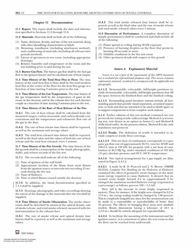
Chapter 11 Documentation
11.1 Report. The report shall include the data and informa-tion specified in Sections 11.2 through 11.8.
11.2 Materials. Materials shall include all of the following:
(1) Name, thickness, density, and size of the test material, alongwith other identifying characteristics or labels
(2) Mounting, installation (including attachment method),and conditioning of materials (including all relevant timeperiods involved)
(3) Layout of specimens in test room (including appropriatedrawings)
(4) Relative humidity and temperature of the room and thetest building prior to and during the test
11.3 Burner Gas Flow. The burner gas flow shall be the fuel gasflow to the ignition burner and its calculated rate of heat output.
11.4 Time History of the Total Heat Flux to Floor. The timehistory of the total heat flux to floor shall be the total incidentheat flux at the center of the floor for the heat flux gauge as afunction of time starting 3 minutes prior to the test.
11.5 Time History of the Gas Temperature. The time history ofthe gas temperature shall be the temperature of gases in theroom, in the doorway, and in the exhaust duct for each thermo-couple as a function of time starting 3 minutes prior to the test.
11.6 Time History of the Rate of Heat Release of the Fire.
11.6.1 The rate of heat release shall be calculated from themeasured oxygen, carbon monoxide, and carbon dioxide con-centrations and the temperature and volumetric flow rate ofthe gas in the duct.
11.6.2 The rate of heat release time history shall be reported,as well as the maximum and average values.
11.6.3 The total heat released time history shall be reported,as well as the final value and the values of both the rate of heatrelease and the total heat released, every 1 minute.
11.7 Time History of the Fire Growth. The time history of thefire growth shall be a transcription of the visual, photographic,audio, and written records of the fire test.
11.7.1 The records shall indicate all of the following:
(1) Time of ignition of the wall finish(2) Approximate location of the flame front most distant
from the ignition source at intervals not exceeding 15 sec-onds during the fire test
(3) Time of flashover(4) Time at which flames extend outside the doorway
11.7.2 In addition, the visual documentation specified in7.1.4 shall be supplied.
11.7.3 Drawings, photographs, and video recordings showingthe extent of the damage to the materials after the test shall besupplied.
11.8 Time History of Smoke Obscuration. The smoke obscu-ration shall be described by means of the optical density, rateof smoke release, and total smoke released, measured with theinstrumentation in the exhaust duct.
11.8.1 The rate of smoke release and optical density timehistory shall be reported, as well as the maximum and averagevalues.
2007 Edition
al Fire Protection Association under license with NFPA
Nor networking permitted without license from IHS
11.8.2 The total smoke released time history shall be re-ported, as well as the final value and the rate of smoke releaseand total smoke released values every 1 minute.
11.9 Discussion of Performance. A complete discussion ofsample performances shall be conducted and shall include allof the following:
(1) Flame spread to ceiling during 40 kW exposure(2) Presence of burning droplets on the floor that persist in
burning 30 seconds or more(3) Visibility conditions in the fire test room(4) Other pertinent details with respect to fire growth
Annex A Explanatory Material
Annex A is not a part of the requirements of this NFPA documentbut is included for informational purposes only. This annex containsexplanatory material, numbered to correspond with the applicable textparagraphs.
A.1.1.2 Demountable, relocatable, full-height partitions in-clude demountable, relocatable, full-height partitions that fillthe space between the finished floor and the finished ceiling.
A.1.1.5 Freestanding panel furniture systems include all free-standing panels that provide visual separation, acoustical separa-tion, or both and that are intended to be used to divide space orto support components to form complete work stations.
A.1.4 Earlier editions of this test method contained two testprotocols for testing textile wallcoverings: Method A (a screen-ing test, now shown as an option in Annex C) and Method B(fully lined walls). In the present edition, Method B is the onlymandatory test protocol.
A.3.3.2 Textile. The definition of textile is intended to in-clude carpets or textile floor coverings.
A.4.1.5.2 This net heat of combustion corresponds to a pro-pane gas flow rate of approximately 26.9 L/min for 40 kW and100.8 L/min at 150 kW, for propane with a net heat of com-bustion of 46.5 MJ/kg, under standard conditions of 101 kPa(15 psi) absolute pressure and 20°C (68°F) temperature.
A.4.1.6 Two typical arrangements for a gas supply are illus-trated in Figure A.4.1.6.
A.4.2.1 A study by R. D. Peacock and J. N. Breese (NBSIR82-2516, Computer Fire Modeling for the Prediction of Flashover)examined the effect of geometric room changes on the mini-mum energy required to cause flashover. It showed that in-creased room height beyond 2.4 m (approximately 8 ft)changed the minimum needed flashover energy (expressed asa percentage) as follows: percent 100 + 5.3 ∆H.
Here ∆H is the increase in room height (expressed inmeters). Thus, for instance, if the height were changed by 0.2 m(7.8 in.), the energy scaling would be changed by 1.06 percent.This is completely insignificant, since few fire measurements canbe made to a repeatability or reproducibility of better than10 percent. The effects of changing floor areas were similarlymodest. Room dimensions having a tolerance of ±0.1 m(±3.9 in.) should be entirely adequate for reproducibility.
A.4.2.4 To facilitate the mounting of the instruments and theignition source, it is convenient to place the test room so thatthe floor can be reached from underneath.
t for Resale The Standard is downloaded from www.bzfxw.com Standard Sharing

265–15ANNEX A
Copyright National FirProvided by IHS undeNo reproduction or ne
A.4.2.6 If self-supporting panels are tested, a separate exte-rior frame or block compartment is not required.
A.5.1.2 It has been shown that the specific adhesive used tosecure a specimen can significantly affect the fire perfor-mance of a wall covering system, and therefore the adhesiveutilized should be the same as that intended for actual use.
A.5.3.1 For products where vaporization of solvents occurs(such as those using adhesives) or products containing wood,a conditioning time of 4 weeks is not uncommon.
A.7.1.1 It is preferable to mount the total heat flux gauge at aheight between 5 mm and 30 mm (0.2 in. and 1.2 in.) abovethe floor surface.
A.7.1.1.1 Maintenance of the heat flux gauge will normallyrequire a flow rate of at least 0.38 L/min (0.1 gpm).
A.7.1.2.2 Metal-clad thermocouples with ceramic powder fill-ing have been found satisfactory for this purpose, but silicone-impregnated, glass-insulated thermocouples are likely tobreak at temperatures above 815°C (1500°F).
Flowmeter
High-volumeregulator*
To burner
Needle valve
4 coils of 9.1 m (30 ft) 12.7 mm (¹⁄₂ in.) copper tubing submerged in water bath508 mm × 939.8 mm × 406.4 mm(20 in. W × 37 in. L × 16 in. D)
*Fisher No. 620-7810 or equivalent
1. Propane gas regulator (high pressure) (main gas supply)
2. Shutoff valve
3. Regulator (low pressure)
4. Adjustable valve for flow impedance
Gas manifold
To burner5
6
1 2 3 4
5. Volume meter
6. Steel braid over tubing to burner
Line pressures are shown.
1.52 m (5 ft)
37.85 L(10 gal)
37.85 L(10 gal)
0.91 m(3 ft)
206 kPa(30 psi)
255 kPa(37 psi) 241 kPa
(35 psi)76 kPa(11 psi)
0.61 m(2 ft)
90.71 kg (200 lb) propane tank
Copper pipe19.1 mm (³⁄₄ in.)
FIGURE A.4.1.6 Two Typical Gas Flow Regulation Systems.
e Protection Association r license with NFPA
Not for Rtworking permitted without license from IHS
--`,,```,,,,````-`-`,,`,,`,`,,`---
A.7.1.4 A window that is cut 0.61 m (2 ft) above the floor inthe front wall facing the gas burner and fitted with heat-resistant, impact-resistant glazing provides useful photo-graphic access. Any floodlights used should not raise the am-bient temperature in the room above what is specified inChapter 6.
A.7.3.2 A bidirectional probe is preferable to a pitot-statictube for measuring velocity in the exhaust duct, in order toavoid problems of clogging with soot. Capacitance transducershave been found to be most stable for this application.
A.7.3.4.1 Stainless steel sampling lines have been shown to besatisfactory. Alternative designs of the sampling line shouldgive equivalent results.
The recommended approach to a cooling column (to re-move water from the combustion gases) is to use a refrigeratedcolumn and separation chamber with a drain plug from whichthe collected water is removed from time to time. Alternativedevices shown to give equivalent results are also acceptable.
A.7.3.4.4 Combustion gas concentration measurements re-quire the use of appropriate time shifts in order to account forthe time required for gas analyzer response and for combus-tion gas transit time within the sampling system.
A.7.3.5 A method for determining suitability of oxygen ana-lyzers for making heat release measurements is as follows:
(1) General. The type of oxygen analyzer best suited for firegas analysis is of the paramagnetic type. Electrochemicalanalyzers or analyzers using zirconia sensors have gener-ally been found not to have adequate sensitivity or suit-ability for this type of work. The normal range of the in-strument to be used is 0 vol to 25 vol percent oxygen.Normally, the linearity of paramagnetic analyzers is betterthan can be checked by a user laboratory; therefore, veri-fying their linearity is not necessary. It is important, how-ever, to confirm the noise and short-term drift of the in-strument used.
(2) Procedure. Check the analyzer suitability using the follow-ing steps:(a) Connect two different gas bottles that are approxi-
mately 2 percentage points apart (for example 15 volpercent and 17 vol percent) to a selector valve at theinlet of the analyzer.
(b) Connect the electrical power and let the analyzerwarm up for 24 hours, with one of the test gases fromA.7.3.5(2)(a) flowing through it.
(c) Connect a data acquisition system to the output of theanalyzer. Quickly switch from the first gas bottle tothe second bottle, and immediately start collectingdata, taking one data point per second. Collect datafor 20 minutes.
(d) Determine the drift by using a least-squares analysis fit-ting procedure to pass a straight line through the last19 minutes of data. Extrapolate the line back throughthe first minute of data. The difference between thereadings at 0 minutes and at 20 minutes on the fittedstraight line represents the short-term drift. Record thedrift in units of parts per million of oxygen.
(e) The noise is represented by the root-mean-square de-viation around the fitted straight line. Calculate thatroot-mean-square value and record it in units of partsper million of oxygen.
2007 Edition
esale The Standard is downloaded from www.bzfxw.com Standard Sharing

265–16 FIRE TESTS FOR EVALUATING ROOM FIRE GROWTH CONTRIBUTION OF TEXTILE COVERINGS
Copyright NationProvided by IHS No reproduction o
(3) Analyzer. The analyzer is suitable for use in heat release mea-surements if the sum of the drift plus the noise terms is50 ppm oxygen (note that both terms must be expressed aspositive numbers).
(4) Additional Precautions. A paramagnetic oxygen analyzer isdirectly sensitive to barometric pressure changes at itsoutlet port and to flow rate fluctuations in the samplesupply stream. It is essential that the flow rate be regu-lated. Use either a flow rate regulator of the mechanicaldiaphragm type or an electronic mass flow rate controller.To protect against errors due to changes in barometricpressure, one of the following procedures should be used:(a) Control the back pressure to the analyzer with a back
pressure regulator of the absolute-pressure type.(b) Electrically measure the actual pressure at the detec-
tor element, and provide a signal correction for theanalyzer output.
See NFPA 271, Standard Method of Test for Heat and VisibleSmoke Release Rates for Materials and Products Using an OxygenConsumption Calorimeter.
A.7.3.8.2.1 The following information is being providedfor informational purposes only and has not been indepen-dently verified, certified, or endorsed by NFPA or any of itstechnical committees. The system described as follows is anexample of a white light measuring system that has beenfound to be satisfactory:
(1) Lenses. Plano convex, diameter 40 mm, focal length50 mm
(2) Lamp. Osram Halo Stars, 64410, 6 V, 10 W, or equivalent(3) Photocell. United Detector Technology, PIN 10 AP, or
equivalent(4) Power Supply. Gresham Lion Ltd, Model G 012, or
equivalent
A.7.3.8.3 It has been shown that white light and laser systemswill give similar results. See the following publications:
(1) “Comparison of Smoke Release Rate from Building Prod-ucts” by B. Ostman.
(2) “Rate of Heat Release Testing for Vinyl Wire and CableMaterials with Reduced Flammability and Smoke: SmallScale and Full Scale Tests” by A. W. Coaker, M. M. Hir-schler, and C. L. Shoemaker.
The following information is being provided for informa-tional purposes only and has not been independently verified,certified, or endorsed by NFPA or any of its technical commit-tees. The system described as follows is an example of a lasermeasuring system that has been found to be satisfactory:
(1) Helium–Neon Laser. Aerotech OEM-05P, or equivalent(2) Laser Power Supply. Aerotech LSS-05, or equivalent(3) Photocells. Hammamatsu S1336-44BK, or equivalent
A.8.2 This calibration is likely to be within 20 percent of thecorrect value.
A.8.4 ASTM E 800, Standard Guide for Measurement of GasesPresent or Generated During Fires, offers guidance on calibratinggas analyzers.
A.10.1 Additional information is contained in an article inFire Technology, “Measuring Rate of Heat Release by OxygenConsumption,” by M. Janssens, pp. 234–249.
--`,,```,,,,````-`-`,,`,,`,`,,`---
2007 Edition
al Fire Protection Association under license with NFPA
Nor networking permitted without license from IHS
A.10.1.2 This velocity profile is obtained by measuring veloc-ity at a sufficient number of representative points over thediameter or cross-section of the duct prior to any fire tests.Detailed procedures for obtaining this profile are describedin The Measurement of Air Flow by E. Ower and R. Pankhurst.Usually, conditions in full-scale fire tests are such that theflow in the duct is turbulent, resulting in a shape factor kc
(equal to the ratio of the average velocity to the velocityalong the centerline) close to 1.
Due to considerable soot production in many fires, pitot-static tubes are generally not useful because of the potentialfor clogging of the holes. To deal with this problem, the bidi-rectional probe described in 7.3.2 was designed by B. J. McCaf-frey and G. Heskestad (“A Robust Bidirectional Low-VelocityProbe for Flame and Fire Application”). This bidirectionalprobe involves measuring the differential pressure across theprobe and the centerline velocity.
A.10.1.4 Water vapor should be removed before the sampleair is introduced into the oxygen analyzer. Use a water trapand desiccant to remove the water.
A.10.1.6 Water vapor must be removed before the sample airis introduced into the oxygen analyzer. Use a water trap anddesiccant to remove the water. The concentration range ofcarbon monoxide in most fires is a small fraction of the con-centration range of carbon dioxide. Hence, the correction forthe heat release rate is generally less than 5 percent. There-fore, carbon monoxide measurements can be ignored.
Annex B Acceptance Criteria
This annex is not a part of the requirements of this NFPA documentbut is included for informational purposes only.
B.1 The acceptance criteria in Section B.2 have been used byseveral of the model code organizations such as the InternationalConference of Building Officials (ICBO), the Building Officialsand Code Administrators International (BOCA), and the South-ern Building Code Congress International (SBCCI) and are pro-vided as a guide for the user of the test method described in thisstandard. Similar criteria have also been in use in the InternationalBuilding Code (IBC) and International Fire Code (IFC), both issued bythe International Code Council (ICC), and in NFPA 101, LifeSafety Code, and NFPA 5000, Building Construction and Safety Code.The acceptance criteria in Section B.3 have been used by thesame codes and continue to be used.
B.2 Textile wall coverings should be considered as demon-strating satisfactory performance if, during the Method A testprotocol (as shown in Annex C), both of the following condi-tions are met:
(1) Flame should not spread to the ceiling during the 40 kWexposure.
(2) During the 150 kW exposure, the following criteria shouldbe met:(a) Flame should not spread to the outer extremity of the
sample on the 2.44 m × 3.66 m (8 ft × 12 ft) wall.(b) The specimen should not burn to the outer extremity
of the 0.6 m (2 ft) wide samples mounted vertically inthe corner of the room.
t for Resale The Standard is downloaded from www.bzfxw.com Standard Sharing

0
F
265–17ANNEX C
Copyright National FirProvided by IHS undeNo reproduction or ne
(c) Burning droplets that are judged to be capable of ignit-ing the textile wall covering or that persist in burningfor 30 seconds or more should not be formed anddropped to the floor.
(d) Flashover should not occur.(e) The maximum instantaneous net peak rate of heat
release should not exceed 300 kW. The maximum in-stantaneous net peak rate of heat release is derived bysubtracting the burner output from the measuredmaximum rate of heat release.
B.3 Textile wall coverings should be considered as demon-strating satisfactory performance if, during the Method B testprotocol, both of the following conditions are met:
(1) Flame should not spread to the ceiling during the 40 kWexposure.
(2) During the 150 kW exposure, the following criteria shouldbe met:(a) Flame should not spread to the outer extremities of
the samples on the 2.44 m × 3.66 m (8 ft × 12 ft) walls.(b) Flashover should not occur.
Note: Burner measures305 mm × 305 mm(1 ft × 1 ft)in plan view. Burnerheight = 305 mm (1 ft).
Floor plan
1.22 m(4 ft)
.22 m(4 ft)
.22 m(4 ft)
2.44 m(8 ft)
2.44 m(8 ft)
0.6 m (2 ft)
0.6 m (2 ft)
6 m (2 ft)
2 m (6 ft 8 in.)
0.76 m (2 ft
Rear wall
Left sidewall
Front wall
GURE C.2.1 Specimen Mounting for Method A Test Protoco
e Protection Association r license with NFPA
Not for Rtworking permitted without license from IHS
--`,,```,,,,````-`-`,,`,,`,`
Annex C Method A Test Protocol
This annex is not a part of the requirements of this NFPA documentbut is included for informational purposes only.
C.1 Method A test protocol is a screening test method that isuseful for testing small amounts of material. The only differ-ence in testing procedure between Test Protocol A and TestProtocol B is the specimen, which does not cover three walls ofthe test room but simply covers a section of the left sidewalland the rear wall as indicated in Section C.2.
C.2 Specimen Mounting and Installation.
C.2.1 The specimen assembly should be installed on the leftsidewall and the rear wall (as viewed from the room door) andas illustrated in Figure C.2.1.
C.2.2 Vertically installed portions of specimen assembliesshould extend 0.6 m (2 ft) from the ceiling and should beinstalled for the full 2.44 m (8 ft) width of the rear wall and thefull 3.66 m (12 ft) length of the left sidewall.
Ceiling plan
2 ft)
Right sidewall
haded areas represent test materials. The test material is applied so machine direction is vertical. The burner is located 51 mm (2 in.) frome rear wall and the left sidewall.
1
1
0.6 m (
.
6 in.)
Note: Sthat theboth th
I l.
2007 Edition
esale
,,`---
The Standard is downloaded from www.bzfxw.com Standard Sharing

265–18 FIRE TESTS FOR EVALUATING ROOM FIRE GROWTH CONTRIBUTION OF TEXTILE COVERINGS
Copyright NationProvided by IHS No reproduction o
C.3 When testing using Method B test protocol the test re-port should note whether burning extended to the outer ex-tremities of the 0.6 m (2 ft) wide samples mounted vertically inthe corner of the room. If burning extended to the outer ex-tremities of the sample, the test report should also note thetime at which such burning occurred.
Annex D Informational References
D.1 Referenced Publications. The documents or portionsthereof listed in this annex are referenced within the informa-tional sections of this standard and are not part of the require-ments of this document unless also listed in Chapter 2 forother reasons.
D.1.1 NFPA Publications. National Fire Protection Associa-tion, 1 Batterymarch Park, Quincy, MA 02169-7471.
NFPA 101®, Life Safety Code®, 2006 edition.NFPA 271, Standard Method of Test for Heat and Visible Smoke
Release Rates for Materials and Products Using an Oxygen Consump-tion Calorimeter, 2004 edition.
NFPA 5000®, Building Construction and Safety Code®, 2006edition.
D.1.2 Other Publications.
D.1.2.1 ASTM Publications. ASTM International, 100 BarrHarbor Drive, P.O. Box C700, West Conshohocken, PA19428-2959.
ASTM E 800, Standard Guide for Measurement of Gases Presentor Generated During Fires, Annual Book of ASTM Standards,Vol. 4.07, 1995.
D.1.2.2 ICC Publications. International Code Council, 5203Leesburg Pike, Suite 600, Falls Church, VA 22041.
International Building Code (IBC), 2006.
--`,,```,,,,````-`-`,,`,,`,`,,`---
International Fire Code (IFC), 2006.
2007 Edition
al Fire Protection Association under license with NFPA
Nor networking permitted without license from IHS
D.1.2.3 NBSIR Publications. National Institute of Standardsand Technology, U.S. Department of Commerce, Fire Re-search Information Service, Building and Fire ResearchLaboratory, 100 Bureau Drive, Stop 8600, Gaithersburg,MD 20899-8600.
NBSIR 82-2516, Computer Fire Modeling for the Prediction ofFlashover, 1982.D.1.2.4 Additional Publications.
Coaker, A. W., M. M. Hirschler, and C. L. Shoemaker. “Rateof Heat Release Testing for Vinyl Wire and Cable Materialswith Reduced Flammability and Smoke: Small Scale and FullScale Tests,” in Proceedings 15th Int. Conf. on Fire Safety,Product Safety Corp., San Francisco, CA, C. J. Hilado, ed.,January 8–12, pp. 220–256, 1990.
Janssens, M. L. “Measuring Rate of Heat Release by OxygenConsumption,” Fire Technology, pp. 234–249, August 1991.
McCaffrey, B. J., and G. Heskestad. “A Robust BidirectionalLow-Velocity Probe for Flame and Fire Application,” Combus-tion and Flame, Vol. 26, No. 1, pp. 125–127, February 1976.
Ostman, B. “Comparison of Smoke Release Rate fromBuilding Products,” International Conference FIRE. Controlthe Heat. . . Reduce the Hazard, London, UK, October 24–25,1988, Fire Research Station, UK, paper 8.
Ower, E., and R. Pankhurst. The Measurement of Air Flow,Pergamon Press, 5th ed., pp. 112–147, 1977.D.2 Informational References. The following documents orportions thereof are listed here as informational resources only.They are not a part of the requirements of this document.
Fisher, F. L., B. MacCracken, and R. B. Williamson. “RoomFire Tests of Textile Wall Coverings,” ES-7853, Service to Indus-try Report No. 85-4, Fire Research Laboratory, University ofCalifornia, Berkeley, CA, April 1986.
Gardon, R. “An Instrument for the Direct Measurement ofIntense Thermal Radiation,” Review of Scientific Instruments,Vol. 24, No. 5, pp. 366–370, May 1953.D.3 References for Extracts in Informational Sections. (Re-
served)t for Resale The Standard is downloaded from www.bzfxw.com Standard Sharing

265–19INDEX
Copyright National FirProvided by IHS undeNo reproduction or ne
Index
Copyright © 2006 National Fire Protection Association. All Rights Reserved.
The copyright in this index is separate and distinct from the copyright in the document that it indexes. The licensing provisions set forth for thedocument are not applicable to this index. This index may not be reproduced in whole or in part by any means without the express written
permission of NFPA.-A-Acceptance criteria . . . . . . . . . . . . . . . . . . . . . . . . . . . . . . . . . . . . . . . . . . . . . . Annex BAdhesives . . . . . . . . . . . . . . . . . . . . . . . . . . . . . . . . . . . . . . . . . . . . . . . . . . . . 5.1.2, A.5.1.2Ambient conditions
Fire roomAir . . . . . . . . . . . . . . . . . . . . . . . . . . . . . . . . . . . . . . . . . . . . . . . . . . . . . . . . . . . . . . . 6.1.1Relative humidity . . . . . . . . . . . . . . . . . . . . . . . . . . . . . . . . . 6.1.3(2), 11.2(4)Temperature . . . . . . . . . . . . . . . . . . . . . . . . . . . . . . . . . . . . . . 6.1.3(1), 11.2(4)
Test buildingRelative humidity . . . . . . . . . . . . . . . . . . . . . . . . . . . . . . . . . . . . 6.2.3, 11.2(4)Temperature . . . . . . . . . . . . . . . . . . . . . . . . . . . . . . . . . . . . . . . . . . 6.2.2, 11.2(4)
Average upper gas layer temperature . . . . . . 1.3.1(7), 1.4.1.3, 1.4.2(3)Definition . . . . . . . . . . . . . . . . . . . . . . . . . . . . . . . . . . . . . . . . . . . . . . . . . . . . . . . . . . 3.3.1
-B-Bidirectional probes . . . . . . . . . . . . . . . . . . . . . . . . . . . 7.3.1(4), 7.3.2, 8.1.3(3),
8.1.3(4), 10.1.1, A.7.3.2Building Officials and Code
Administrators International (BOCA) . . . . . . . . . . . . . . . . B.1Burners . . . . . . . . . . . . . . . . . . . . . . . . . . . . . . . . . . . . . . . . . . . . . . . . . . . .see Gas burners
-C-Calculations . . . . . . . . . . . . . . . . . . . . . . . . . . . . . . . . . . . . . . . . . . . . . . . . . . . . . Chap. 10Calibration . . . . . . . . . . . . . . . . . . . . . . . . . . . . . . . . . . . . . . . . . . . . . . . . . . . . . . . . Chap. 8
Gas analyzers . . . . . . . . . . . . . . . . . . . . . . . . . . . . . . . . . . . . . . . . . . . . . . . . . 8.4, A.8.4Heat flux gauge . . . . . . . . . . . . . . . . . . . . . . . . . . . . . . . . . . . . . . . . . . . . . . . . . 7.1.1.4Heat release measurements . . . . . . . . . . . . . . . . . . . . . . . . . . . . . . . . 8.2, A.8.2Ignition source . . . . . . . . . . . . . . . . . . . . . . . . . . . . . . . . . . . . . . . . . . . . . . . . . . . . . . 8.1Smoke measurement . . . . . . . . . . . . . . . . . . . . . . . . . . . . . . . . . . . . . . . . . . . . . . . 8.3Test equipment . . . . . . . . . . . . . . . . . . . . . . . . . . . . . . . . . . . . . . . . . . . . . . . . . . . . . . 8.1
Carbon dioxide concentration . . . . . . . . . . . . . . . . . . . . . . . . . . . . . 7.3.6, 11.6.1Carbon monoxide . . . . . . . . . . . . . . . . . . . . . . . . . . . . . . . . . . . . . . . . . . . . . . . . 1.3.1(9)
Concentration . . . . . . . . . . . . . . . . . . . . . . . . . . . . . . . . . . . . . . . . . . . . 7.3.7, 11.6.1Release rate . . . . . . . . . . . . . . . . . . . . . . . . . . . . . . . . . . . . . . . . . . . . . . . . . . . . . . 10.3.1
Combustion gases . . . . . . . . . . . . . . . . . . . . . . . . . . . .see also Carbon monoxide;Gas sampling/analysis systems
Concentrations . . . . . . . . . . 1.4.1.5, 7.3.4 to 7.3.7, A.7.3.4.1 to A.7.3.5Emissions of . . . . . . . . . . . . . . . . . . . . . . . . . . . . . . . . . . . . . . . . . . . . . . . . . . 1.3.1(10)Flow rate . . . . . . . . . . . . . . . . . . . . . . . . . . . . . . . . . . . . . . . . . . . . . . . .see Gas velocityRelease rates of . . . . . . . . . . . . . . . . . . . . . . . . . . . . . . . . . . . . . . . . . . . . . . . . . . . . 10.3Temperature, time history of . . . . . . . . . . . . . . . . . . . . . . . . . . . . . . . . . . . . . 11.5Toxicity of . . . . . . . . . . . . . . . . . . . . . . . . . . . . . . . . . . . . . . . . . . . . . . . . . . . . . . 1.3.3(1)
Compartment geometry and construction . . . . . 4.2, A.4.2.1 to A.4.2.6
-D-Definitions . . . . . . . . . . . . . . . . . . . . . . . . . . . . . . . . . . . . . . . . . . . . . . . . . . . . . . . . Chap. 3Documentation . . . . . . . . . . . . . . . . . . . . . . . . . . . . . . . . . . . . . . . . . . . . . 9.2, Chap. 11
Ignition source . . . . . . . . . . . . . . . . . . . . . . . . . . . . . . . . . . . . . . . . . . . . . . . . . . . . . . 8.1Photographic and video . . . . . . . . . . . . . . . . . . . . . . . . . . . . . . . . 11.7.2, 11.7.3Photographic/video records . . . . . . . . . . . . . . . . . . . 7.1.4, 9.2(4), A.7.1.4Test equipment . . . . . . . . . . . . . . . . . . . . . . . . . . . . . . . . . . . . . . . . . . . . . . . . . . . . . . 8.1
Ducts, exhaust . . . . . . . . . . . . . . . . . . . . . . . . . . . . . . . . . . . . . . . . . .see Exhaust ducts
-E-Environmental conditions . . . . . . . . . . . . . . . . . . . . . . . . . . . . . . . . . . . . . . . Chap. 6Exhaust ducts . . . . . . . . . . . . . . . . . . . . . . . . . . . . . . . . . . . . . . . . . . . 1.4.1.5, 7.2, 11.5
Alternative design . . . . . . . . . . . . . . . . . . . . . . . . . . . . . . . . . . . . . . . . . . . . . . . . . 7.2.3Instrumentation in . . . . . . . . . . . . . . . . . . . . . . . . . . 7.3, A.7.3.2 to A.7.3.8.3
Exhaust gases . . . . . . . . . . . . . . . . . . . . . . . . . . . . . . . . . . . . . .see Combustion gases
e Protection Association r license with NFPA
Not for Rtworking permitted without license from IHS
-F-Fire growth . . . . . . . . . . . . . . . . . . . . . . . . . . . . . . . . . . . . . . 1.2.2, 1.4.1.3, 11.7, 11.9Fire resistance . . . . . . . . . . . . . . . . . . . . . . . . . . . . . . . . . . . . . . . . . . . . . . . . . . . . 1.3.3(2)Fire room
Environment . . . . . . . . . . . . . . . . . . . . . . . . . . . . . . . . . . . . . . . . . . . . . . . . . . . . . . . . 6.1Geometry and construction . . . . . . . . . . . . . . . . . . . 4.2, A.4.2.1 to A.4.2.6Instrumentation . . . . . . . . . . . . . . . . . . . . . . . . . . . . . . . . 7.1, A.7.1.1 to A.7.1.4
Flame extension beyond doorway . . . . . . . . . . 1.3.1(5), 1.4.2(4), 9.2(5),11.7.1(4)
Flame front, location of . . . . . . . . . . . . . . . . . . . . . . . . . . . . . . . . . . . . . . . . 11.7.1(2)Flame spread . . . . . . . . . . . . . . . . . . . . . . . . . . . 1.3.1(5), 7.1.4, 11.9(1), A.7.1.4,
B.2, B.3Flashover . . . 1.3.1(4), 1.4.1.3, 1.4.2, 9.2(5), 11.7.1(3), B.2(2), B.3(2)
Paper target indicators . . . . . . . . . . . . . . . . . . . . . . . . . . . . . . . . . . . . . . . . . . . 7.1.3Floor, heat flux at . . . . . . . . . . . . . . . . . . . . . . 1.3.1(6), 1.4.1.3, 1.4.2(2), 11.4Flow rate . . . . . . . . . . . . . . . . . . . . . . . . . . . . . . . . . . . . . . . . . . . . . . . . . . .see Gas velocityFreestanding panel furniture systems . . . . . . . . . . . . . . . . . . . . 1.1.5, A.1.1.5
-G-Gardon (foil) heat flux gauge . . . . . . . . . . . . . . . . . . . . . . . . . . . . . . . . . . . . 7.1.1.1Gas, combustion . . . . . . . . . . . . . . . . . . . . . . . . . . . . . . . . . . .see Combustion gasesGas burners . . . . . . . . . . . . . . . . . . . . . . . . . . . . . . . . . . . . . . . . . . . . . . . . . . . . . . . . 1.4.1.1
Calibration . . . . . . . . . . . . . . . . . . . . . . . . . . . . . . . . . . . . . . . . . . . . . . . . . . . . . 8.1.3(2)Gas flow
Report of . . . . . . . . . . . . . . . . . . . . . . . . . . . . . . . . . . . . . . . . . . . . . . . . . . . . . . . . 11.3Ignition of . . . . . . . . . . . . . . . . . . . . . . . . . . . . . . . . . . . . . . . . . . . . . . . . . . . . . . . . 9.2(3)Shut off of . . . . . . . . . . . . . . . . . . . . . . . . . . . . . . . . . . . . . . . . . . . . . . . . . . . . . . . . 9.2(6)Specifications . . . . . . . . . . . . . . . . . . . . . . . . . . . . . . . . . . . 4.1, A.4.1.5.2, A.4.1.6
Gas sampling/analysis systems . . . . . . . . . . . . . . . . . 7.3.1(8), 7.3.4 to 7.3.7,A.7.3.4.1 to A.7.3.5
Calibration . . . . . . . . . . . . . . . . . . . . . . . . . . . . . . . . . . . . . . . . . . . . . . . . . . . 8.4, A.8.4Sampling line tubes . . . . . . . . . . . . . . . . . . . . . . . . 7.3.4, A.7.3.4.1, A.7.3.4.4
Gas train . . . . . . . . . . . . . . . . . . . . . . . . . . . . . . . . . . . . . . . . . . . . . . . . . . . . . . . . . . . . 7.3.4.2Gas velocity
Flow rate equations . . . . . . . . . . . . . . . . . . . . . . . . . . . . . . . . . . . . . . . 10.1, A.10.1Measurement of . . . . . . . . . . . . . . . . . . . . . . . . . . . . . . . . 1.4.1.5, 7.3.2, A.7.3.2
-H-Heat flux
Floor . . . . . . . . . . . . . . . . . . . . . . . . . . . . . . . . . . 1.3.1(6), 1.4.1.3, 1.4.2(2), 11.4Gauge . . . . . . . . . . . . . . . . . . . . . . . . . . . . . . . . . . . . . . . . . . . . . . . 7.1.1, 11.4, A.7.1.1
Heat releaseMeasurements . . . . . . . . . . . . . . . . . . . . . . . . . . . . . . . . . . . . . . . . . . . . . . . . 8.2, A.8.2Rate . . . . . . . . . . . . . . . . . . . . . . . 1.3.1(2), 1.4.1.2, 1.4.1.3, 1.4.2(1), 9.2(3)
Calculations . . . . . . . . . . . . . . . . . . . . . . . . . . . . . . . . . . . . . . . . . . . . . . . Chap. 10Time history of . . . . . . . . . . . . . . . . . . . . . . . . . . . . . . . . . . . . . . . . . . . . . . . . . . 11.6
Total . . . . . . . . . . . . . . . . . . . . . . . . . . . . . . . . . . . . . . . . . . . . . . . . . . . . . . . . . . . . 1.3.1(3)Calculations . . . . . . . . . . . . . . . . . . . . . . . . . . . . . . . . . . . . . . . . 10.1.6, A.10.1.6Time history . . . . . . . . . . . . . . . . . . . . . . . . . . . . . . . . . . . . . . . . . . . . . . . . . . . . . 11.6
Hood . . . . . . . . . . . . . . . . . . . . . . . . . . . . . . . . . . . . . . . . . . . . . . . . 1.4.1.5, 7.2, 7.3.1(2)Humidity, relative
Fire room . . . . . . . . . . . . . . . . . . . . . . . . . . . . . . . . . . . . . . . . . . . . 6.1.3(2), 11.2(4)Specimen conditioning . . . . . . . . . . . . . . . . . . . . . . . . . . . . . . . . . 5.3.1, A.5.3.1Test building . . . . . . . . . . . . . . . . . . . . . . . . . . . . . . . . . . . . . . . . . . . . 6.2.3, 11.2(4)
-I-Ignition, times of . . . . . . . . . . . . . . . . . . . . . . . . . . . . . . . . . . . . . . . . . . . . . . . . . . . 9.2(5)Ignition source . . . . . . . . . . . . . . . . . . . . . . . . . . . . . . . . 4.1, 8.1, A.4.1.5.2, A.4.1.6Instrumentation . . . . . . . Chap. 7; see also Bidirectional probes; Exhaust
ducts; Gas sampling/analysis systems; ThermocouplesCalibration . . . . . . . . . . . . . . . . . . . . . . . . . . . . . . . . . . . . . . . . . . . . . . . . . . . . . . . . . 8.1.1
2007 Edition
esale
--`,,```,,,,````-`-`,,`,,`,`,,`---
The Standard is downloaded from www.bzfxw.com Standard Sharing

265–20 FIRE TESTS FOR EVALUATING ROOM FIRE GROWTH CONTRIBUTION OF TEXTILE COVERINGS
Copyright NationProvided by IHS No reproduction o
Heat flux gauges . . . . . . . . . . . . . . . . . . . . . . . . . . . . . . . . . . . 7.1.1, 11.4, A.7.1.1Paper target flashover indicators . . . . . . . . . . . . . . . . . . . . . 1.4.2(5), 7.1.3Photographic/video equipment . . . . . . . . . . . . . . . . . . . . . . . 7.1.4, A.7.1.4
Interior dimensions, fire room . . . . . . . . . . . . . . . . . . 4.2, A.4.2.1 to A.4.2.6International Conference of Building Officials (ICBO) . . . . . . . . . . B.1
-L-Laser light obscuration measurement system . . . . . . . . . . . . . . . . . . . 7.3.8.2,
7.3.8.3, A.7.3.8.3
-M-Method A test protocol . . . . . . . . . . . . . . . . . . . . . . . . . . . . . . . . . . A.1.4, Annex CMethod B test protocol, use of . . . . . . . . . . . . . . . . . . 1.4.1, 5.2.1, 9.1, A.1.4Mounting
Heat flux gauge . . . . . . . . . . . . . . . . . . . . . . . . . . . . . . . . . . . . . . . . . . 7.1.1, A.7.1.1Specimens . . . . . . . . . . . . . . . . . . . . . . . . . . . . . . . . . 1.4.1, 5.1, 11.2(2), A.5.1.2
-O-Oxygen analyzers . . . . . . . . . . . . . . . . . . . .see Gas sampling/analysis systemsOxygen concentration . . . . . . 7.3.1(6), 7.3.4.2(8), 7.3.5, 11.6.1, A.7.3.5Oxygen depletion factor . . . . . . . . . . . . . . . . . . . . . . . . . . . . . . . . 10.1.4, A.10.1.4
-P-Panel furniture systems, freestanding . . . . . . . . . . . . . . . . . . . . 1.1.5, A.1.1.5Paper target flashover indicators . . . . . . . . . . . . . . . . . . . . . . . . 1.4.2(5), 7.1.3Partitions, demountable, relocatable, full-height . . . . . . . . 1.1.2, A.1.1.2Performance
Acceptance criteria . . . . . . . . . . . . . . . . . . . . . . . . . . . . . . . . . . . . . . . . . . . Annex BDiscussion of . . . . . . . . . . . . . . . . . . . . . . . . . . . . . . . . . . . . . . . . . . . . . . . . . . . . . . . 11.9
Photographic records . . . . . . . . . . . . . 7.1.4, 9.2(4), 11.7.2, 11.7.3, A.7.1.4Photometer system . . . . . . . . . . . . 7.3.8.1 to 7.3.8.3, A.7.3.8.2.1, A.7.3.8.3Probes, bidirectional . . . . . . . . . . . . . . . . . . . . . . . . . . . .see Bidirectional probesPurpose of standard . . . . . . . . . . . . . . . . . . . . . . . . . . . . . . . . . . . . . . . . . . . . . . . . . . . 1.2
-R-References . . . . . . . . . . . . . . . . . . . . . . . . . . . . . . . . . . . . . . . . . . . . . . . . . . . . . . . Annex DReports . . . . . . . . . . . . . . . . . . . . . . . . . . . . . . . . . . . . . . . . . . . . . . . . . . . . . . . . . . . . . . . . 11.1
-S-Schmidt–Boelter (thermopile) heat flux gauge . . . . . . . . . . . . . . . . . 7.1.1.1Scope of standard . . . . . . . . . . . . . . . . . . . . . . . . . . . . . . . . . . . 1.1, A.1.1.2, A.1.1.5Shall (definition) . . . . . . . . . . . . . . . . . . . . . . . . . . . . . . . . . . . . . . . . . . . . . . . . . . . . . 3.2.1Should (definition) . . . . . . . . . . . . . . . . . . . . . . . . . . . . . . . . . . . . . . . . . . . . . . . . . . 3.2.2
2007 Edition
al Fire Protection Association under license with NFPA
Nor networking permitted without license from IHS
Smoke obscuration . . . . . . . . . . . . . . . . . . . . . . . . . . . . . . . . . . . . . . . . . . . . . . . 1.3.1(8)Measurement . . . . . . . . . . . . . . . . . . 7.3.1(7), 7.3.8, A.7.3.8.2.1, A.7.3.8.3
Calibration . . . . . . . . . . . . . . . . . . . . . . . . . . . . . . . . . . . . . . . . . . . . . . . . . . . . . . . . 8.3Equations . . . . . . . . . . . . . . . . . . . . . . . . . . . . . . . . . . . . . . . . . . . . . . . . . . . . . . . . 10.2
Time history of . . . . . . . . . . . . . . . . . . . . . . . . . . . . . . . . . . . . . . . . . . . . . . . . . . . . . 11.8Smoke release . . . . . . . . . . . . . . . . . . . . . . . . . . . . . . . . . . . . . . . . . . . . . . . . . . . . . . 1.4.1.3
Rate of . . . . . . . . . . . . . . . . . . . . . . . . . . . . . . . . . . . . . . . . . . . . . . . . . . . . . . 10.2.4, 11.8Total . . . . . . . . . . . . . . . . . . . . . . . . . . . . . . . . . . . . . . . . . . . . . . . . . . . . . . . . 10.2.5, 11.8
Southern Building Code Congress International (SBCCI) . . . . . . . . B.1Specimens
Conditioning . . . . . . . . . . . . . . . . . . . . . . . . . . . . . . . . . . . . . 5.3, 11.2(2), A.5.3.1Installation . . . . . . . . . . . . . . . . . . . . . . . . . . . . . . . . . . . . . . . . . . . . . . . . . 5.2, 11.2(2)Layout in test room . . . . . . . . . . . . . . . . . . . . . . . . . . . . . . . . . . . . . . . . . . . . 11.2(3)Mounting . . . . . . . . . . . . . . . . . . . . . . . . . . . . . . . . . . 1.4.1, 5.1, 11.2(2), A.5.1.2
Standard (definition) . . . . . . . . . . . . . . . . . . . . . . . . . . . . . . . . . . . . . . . . . . . . . . . . 3.2.3Summary of test method . . . . . . . . . . . . . . . . . . . . . . . . . . . . . . . . . . . . . . . 1.4, A.1.4Symbols . . . . . . . . . . . . . . . . . . . . . . . . . . . . . . . . . . . . . . . . . . . . . . . . . . . . . . . . . . . . . . . . 10.4
-T-Temperature
AmbientFire room . . . . . . . . . . . . . . . . . . . . . . . . . . . . . . . . . . . . . . . . . . . . . . . . . . . 6.1.3(1)Test building . . . . . . . . . . . . . . . . . . . . . . . . . . . . . . . . . . . . . . . . . . . . . . . . . . . 6.2.2
Average upper gas layer . . . . . . . . . . . . . . . . . . 1.3.1(7), 1.4.1.3, 1.4.2(3)Definition . . . . . . . . . . . . . . . . . . . . . . . . . . . . . . . . . . . . . . . . . . . . . . . . . . . . . . . 3.3.1
Combustion gases . . . . . . . . . . . . . . . . . . . . . . . . . . . . . . . . . . . . . . . . 1.4.1.5, 11.5Specimen conditioning . . . . . . . . . . . . . . . . . . . . . . . . . . . . . . . . . 5.3.1, A.5.3.1During test
Fire room . . . . . . . . . . . . . . . . . . . . . . . . . . . . . . . . . . . . . . . . . . . . . . . . . . . . 11.2(4)Test building . . . . . . . . . . . . . . . . . . . . . . . . . . . . . . . . . . . . . . . . . . . . . . . . 11.2(4)
Termination of test . . . . . . . . . . . . . . . . . . . . . . . . . . . . . . . . . . . . . . . . . . . . . . . . . 9.2(6)Test equipment . . . . . . . . . . . . . . . . . . . . . . . . . . . . . . . . . . . . . . . . . . . . . . . . . . . Chap. 5
Calibration and documentation . . . . . . . . . . . . . . . . . . . . . . . . . . . . . . . . . . . 8.1Compartment geometry and construction . . 4.2, A.4.2.1 to A.4.2.6Ignition source . . . . . . . . . . . . . . . . . . . . . . . . . . . . . . . . . 4.1, A.4.1.5.2, A.4.1.6
Test procedure . . . . . . . . . . . . . . . . . . . . . . . . . . . . . . . . . . . . . . . . . . . . . . . . . . . . Chap. 9Textile (definition) . . . . . . . . . . . . . . . . . . . . . . . . . . . . . . . . . . . . . . . . . 3.3.2, A.3.3.2Thermocouples . . . . . . . . . . . . . . . . . . . 7.1.2, 7.3.1(5), 7.3.3, 11.5, A.7.1.2.2Time history reports . . . . . . . . . . . . . . . . . . . . . . . . . . . . . . . . . . . . . . . . . 11.4 to 11.8Total heat flux gauge . . . . . . . . . . . . . . . . . . . . . . . . . . . . . . . . . . . . . . . 7.1.1, A.7.1.1
-V-Ventilation
Fire room . . . . . . . . . . . . . . . . . . . . . . . . . . . . . . . . . . . . . . . . . . . . . . . . . 1.4.1.4, 4.2.5Test building . . . . . . . . . . . . . . . . . . . . . . . . . . . . . . . . . . . . . . . . . . . . . . . . . . . . . . 6.1.1
Smoke accumulation . . . . . . . . . . . . . . . . . . . . . . . . . . . . . . . . . . . . . . . . . . . . . . . . 6.2.1 Video records . . . . . . . . . . . . . . . . . . . . . . 7.1.4, 9.2(4), 11.7.2, 11.7.3, A.7.1.4
Cou/D06 07 08 09 6 5 4 3 2 1
t for Resale
--`,,```,,,,````-`-`,,`,,`,`,,`---
The Standard is downloaded from www.bzfxw.com Standard Sharing

Sequence of Events Leading to Issuance of an NFPA Committee Document
Step 1: Call for Proposals
• Proposed new Document or new edition of an existing Document is entered into one of two yearly revision cy-cles, and a Call for Proposals is published.
Step 2: Report on Proposals (ROP)
• Committee meets to act on Proposals, to develop its own Proposals, and to prepare its Report.
• Committee votes by written ballot on Proposals. If two-thirds approve, Report goes forward. Lacking two-thirds approval, Report returns to Committee.
• Report on Proposals (ROP) is published for public re-view and comment.
Step 3: Report on Comments (ROC)
• Committee meets to act on Public Comments to develop its own Comments, and to prepare its report.
• Committee votes by written ballot on Comments. If two-thirds approve, Report goes forward. Lacking two-thirds approval, Report returns to Committee.
• Report on Comments (ROC) is published for public re-view.
Step 4: Technical Report Session
• “Notices of intent to make a motion” are filed, are reviewed, and valid motions are certified for presentation at the Technical Report Session. (“Consent Documents” that have no certified motions bypass the Technical Report Session and proceed to the Standards Council for issu-ance.)
• NFPA membership meets each June at the Annual Meet-ing Technical Report Session and acts on Technical Committee Reports (ROP and ROC) for Documents with “certified amending motions.”
• Committee(s) vote on any amendments to Report ap-proved at NFPA Annual Membership Meeting.
Step 5: Standards Council Issuance
• Notification of intent to file an appeal to the Standards Council on Association action must be filed within 20 days of the NFPA Annual Membership Meeting.
• Standards Council decides, based on all evidence, whether or not to issue Document or to take other ac-tion, including hearing any appeals.
Committee Membership ClassificationsThe following classifications apply to Technical Commit-tee members and represent their principal interest in the activity of the committee.
M Manufacturer: A representative of a maker or mar-keter of a product, assembly, or system, or portion thereof, that is affected by the standard.
U User: A representative of an entity that is subject to the provisions of the standard or that voluntarily uses the standard.
I/M Installer/Maintainer: A representative of an entity that is in the business of installing or maintaining a product, assembly, or system affected by the stan-dard.
L Labor: A labor representative or employee con-cerned with safety in the workplace.
R/T Applied Research/Testing Laboratory: A representative of an independent testing laboratory or indepen-dent applied research organization that promul-gates and/or enforces standards.
E Enforcing Authority: A representative of an agency or an organization that promulgates and/or en-forces standards.
I Insurance: A representative of an insurance com-pany, broker, agent, bureau, or inspection agency.
C Consumer: A person who is, or represents, the ul-timate purchaser of a product, system, or service affected by the standard, but who is not included in the User classification.
SE Special Expert: A person not representing any of the previous classifications, but who has a special expertise in the scope of the standard or portion thereof.
NOTES;1. “Standard” connotes code, standard, recommended practice, or guide.2. A representative includes an employee.3. While these classifications will be used by the Standards Council to achieve a balance for Technical Committees, the Standards Council may determine that new classifi-cations of members or unique interests need representa-tion in order to foster the best possible committee delib-erations on any project. In this connection, the Standards Council may make appointments as it deems appropriate in the public interest, such as the classification of “Utili-ties” in the National Electrical Code Committee.4. Representatives of subsidiaries of any group are gener-ally considered to have the same classification as the par-ent organization.
Copyright National Fire Protection Association Provided by IHS under license with NFPA
Not for ResaleNo reproduction or networking permitted without license from IHS
--`,,```,,,,````-`-`,,`,,`,`,,`---
The Standard is downloaded from www.bzfxw.com Standard Sharing

NFPA Technical Committee Document Proposal Form
NOTE: All Proposals must be received by 5:00 p.m. EST/EDST on the published Proposal Closing Date.
For further information on the standards-making process, please contact the Codes and Standards Administration at 617-984-7249.
For technical assistance, please call NFPA at 617-770-3000.
FOR OFFICE USE ONLY
Log #:
Date Rec’d:
Please indicate in which format you wish to receive your ROP/ROC electronic paper download (Note: If choosing the download option, you must view the ROP/ROC from our website; no copy will be sent to you.)
Date April 1, 200X Name John J. Doe Tel. No. 716-555-1234
Company Air Canada Pilot's Association
Street Address 123 Summer Street Lane City Lewiston State NY Zip 14092
Please indicate organization represented (if any)
1. (a) NFPA Document Title National Fuel Gas Code NFPA No. & Year 54, 200X Edition
(b) Section/Paragraph 3.3
2. Proposal Recommends (check one): new text revised text deleted text
3. Proposal (include proposed new or revised wording, or identification of wording to be deleted): [Note: Proposed text should be in legislative format, i.e., use underscore to denote wording to be inserted (inserted wording) and strike-through to denote wording to be deleted (deleted wording).]
Revise definition of effective ground-fault current path to read:
3.3.78 Effective Ground-Fault Current Path. An intentionally constructed, permanent, low impedance electrically conductive path designed and intended to carry underground electric fault current conditions from the point of a ground fault on a wiring system to the electrical supply source.
4. Statement of Problem and Substantiation for Proposal: (Note: State the problem that would be resolved by your recommendation; give the specific reason for your Proposal, including copies of tests, research papers, fire experience, etc. If more than 200 words, it may be abstracted for publication.)
Change uses proper electrical terms.
5. Copyright Assignment
(a) I am the author of the text or other material (such as illustrations, graphs) proposed in this Proposal.
(b) Some or all of the text or other material proposed in this Proposal was not authored by me. Its source is as follows (please identify which material and provide complete information on its source):
ABC Co.
I hereby grant and assign to NFPA all and full rights in copyright in this Proposal and understand that I acquire no rights in any publication of NFPA in which this Proposal in this or another similar or analogous form is used. Except to the extent that I do not have authority to make an assignment in materials that I have identified in (b) above, I hereby warrant that I am the author of this Proposal and that I have full power and authority to enter into this assignment.
Signature (Required)
PLEASE USE SEPARATE FORM FOR EACH PROPOSAL • NFPA Fax: (617) 770-3500 Mail to: Secretary, Standards Council, National Fire Protection Association, 1 Batterymarch Park, Quincy, MA 02169-7471
8/29/2006
Copyright National Fire Protection Association Provided by IHS under license with NFPA
Not for ResaleNo reproduction or networking permitted without license from IHS
--`,,```,,,,````-`-`,,`,,`,`,,`---
The Standard is downloaded from www.bzfxw.com Standard Sharing

NFPA Technical Committee Document Proposal Form
NOTE: All Proposals must be received by 5:00 p.m. EST/EDST on the published Proposal Closing Date.
For further information on the standards-making process, please contact the Codes and Standards Administration at 617-984-7249.
For technical assistance, please call NFPA at 617-770-3000.
FOR OFFICE USE ONLY
Log #:
Date Rec’d:
Please indicate in which format you wish to receive your ROP/ROC electronic paper download (Note: If choosing the download option, you must view the ROP/ROC from our website; no copy will be sent to you.)
Date Name Tel. No.
Company
Street Address City State Zip
Please indicate organization represented (if any)
1. (a) NFPA Document Title NFPA No. & Year
(b) Section/Paragraph
2. Proposal Recommends (check one): new text revised text deleted text
3. Proposal (include proposed new or revised wording, or identification of wording to be deleted): [Note: Proposed text should be in legislative format, i.e., use underscore to denote wording to be inserted (inserted wording) and strike-through to denote wording to be deleted (deleted wording).]
4. Statement of Problem and Substantiation for Proposal: (Note: State the problem that would be resolved by your recommendation; give the specific reason for your Proposal, including copies of tests, research papers, fire experience, etc. If more than 200 words, it may be abstracted for publication.)
5. Copyright Assignment
(a) I am the author of the text or other material (such as illustrations, graphs) proposed in this Proposal.
(b) Some or all of the text or other material proposed in this Proposal was not authored by me. Its source is as follows (please identify which material and provide complete information on its source):
I hereby grant and assign to NFPA all and full rights in copyright in this Proposal and understand that I acquire no rights in any publication of NFPA in which this Proposal in this or another similar or analogous form is used. Except to the extent that I do not have authority to make an assignment in materials that I have identified in (b) above, I hereby warrant that I am the author of this Proposal and that I have full power and authority to enter into this assignment.
Signature (Required)
PLEASE USE SEPARATE FORM FOR EACH PROPOSAL • NFPA Fax: (617) 770-3500 Mail to: Secretary, Standards Council, National Fire Protection Association, 1 Batterymarch Park, Quincy, MA 02169-7471
8/29/2006
Copyright National Fire Protection Association Provided by IHS under license with NFPA
Not for ResaleNo reproduction or networking permitted without license from IHS
--`,,```,,,,````-`-`,,`,,`,`,,`---
The Standard is downloaded from www.bzfxw.com Standard Sharing