NFOR HOT-FILM VELOCITY MEASUREMENT UNCERTAINTY · Model 1174 Barocel Electronic Manometer with a 10...
45
David Taylor Research Center Bethesda, MD 20084-5000 AD-A220 002 DTRC/SHD-1298-05 MARCH 1990 Ship Hydromechanics Department Technical Report 0 HOT-FILM VELOCITY MEASUREMENT UNCERTAINTY NFOR DARPA SUBOFF EXPERIMENTS By James N. Blanton EThomas J. Forlini L. Patrick Purtell >" APPROVED FOR PUBLIC RELEASE: Distribution Unlimited 0 E LECTE 8 APR 02 1990
Transcript of NFOR HOT-FILM VELOCITY MEASUREMENT UNCERTAINTY · Model 1174 Barocel Electronic Manometer with a 10...

David Taylor Research CenterBethesda, MD 20084-5000
AD-A220 002
DTRC/SHD-1298-05 MARCH 1990
Ship Hydromechanics Department
Technical Report
0
HOT-FILM VELOCITY MEASUREMENT UNCERTAINTYNFOR DARPA SUBOFF EXPERIMENTS
By
James N. BlantonEThomas J. Forlini
L. Patrick Purtell
>" APPROVED FOR PUBLIC RELEASE:Distribution Unlimited
0 E LECTE8 APR 02 1990
CODE 011 DIRECTOR OF TECHNOLOGY, PLANS AND ASSESSMENT
12 SHIP SYSTEMS INTEGRATION DEPARTMENT
14 SHIP ELECTROMAGNETIC SIGNATURES DEPARTMENT
15 SHIP HYDROMECHANICS DEPARTMENT
16 AVIATION DEPARTMENT
17 SHIP STRUCTURES AND PROTECTION DEPARTMENT
18 COMPUTATION, MATHEMATICS & LOGISTICS DEPARTMENT
19 SHIP ACOUSTICS DEPARTMENT
27 PROPULSION AND AUXILIARY SYSTEMS DEPARTMENT
28 SHIP MATERIALS ENGINEERING DEPARTMENT
DTRC ISSUES THREE TYPES OF REPORTS:
1. DTRC reports, a formal series, contain information of permanent technical value.They carry a consecutive numerical identification regardless of their classification or theoriginating department.
2. Departmental reports, a semiformal series, contain information of a preliminary,temporary, or proprietary nature or of limited interest or significance. They carry adepartmental alphanumerical identification.
3. Technical memoranda, an Informal series, contain technical documentation oflimited use and interest. They are primarily working papers intended for internal use. Theycarry an identifying number which indicates their type and the numerical code of theoriginating department. Any distribution outside DTRC must be approved by the head ofthe originating department on a case-by-case basis.
N0W-DTNSROC WO2/51 (Rev. 2-68)
UJNCLASSIFIEDSECURITY CLASSIFICATION OF THIS PAGE
REPORT DOCUMENTATION PAGEla REPORT SECURITY CLASSIFICATION lb RESTRICTIVE MARKINGS
UNCLASSIFIED2a SECURITY CLASSIFICATION -AUTHORITY 3 DISTRIBUTION /AVAILABILITY OF REPORT
APPROVED FOR PUBLIC RELEASE2b. DECLASSIFICATION /DOWNGRADING SCHEDULE Distribution Unlimited
4 PERFORMING ORGANIZATION REPORT NUMBER(S) S. MONITORING ORGANIZATION REPORT NUMBER(S)
DTRC/SHD-1298-05
6a. NAME OF PERFORMING ORGANIZATION 6b OFFICE SYMBOL 7a. NAME OF MONITORING ORGANIZATION
David Taylor Research Center (If applicable)I Code 1543
6c. ADDRESS (City, State, and ZIP Code) 7b. ADDRESS (City. State, and ZIP Code)
Bethesda, MD 20084-5000
Ba. NAME OF FUNDING/SPONSORING 8b OFFICE SYMBOL 9- PROCUREMENT INSTRUMENT IDENTIFICATION NUMBERORGANIZATION (If applicable)
Defense Advanced Research Agen r
Sc ADDRESS (City, State. and ZIPCode) 10 SOURCE OF FUNDING NUMBERSSubmarine Technology Office PROGRAM PROJECT TASK WORK UNIT
STP Support Office ELEMENT NO NO NO ACCESSION NO
1515 wilson Blvd, Suite 705, VA 2220911 TITLE (Include Security Classification)HOT-FILM VELOCITY MEASUREMENT UNCERTAINTY FOR DARPA SUBOFF EXPERIMENTS
12 PFRSONAL AUTHOR(S)James N. Blanton, Thomas J. Forlini and L.Patrick Purtell
13a. TYPE OF REPORT 113b TIME COVERED 114 DATE OF REPORT (Year. Month, Day) S PAGE COUNTDepartmental IFROM TO MARCH 1990
16 SUPPLEMENTARY NOTATION
17 COSATI CODES 18 SUBJECT TERMS (Continue on reverse if necessary and identify by block number)FIELD GROUP I SUB-GROUP
19 ABSTRACT (Continue on reverse if necessary and identify by block number)
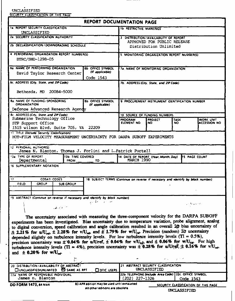
The uncertainty associated with measuring the three-component velocity for the DARPA SUBOFFexperiments has been investigated. Bias uncertainty due to temperature variation, probe alignment, analogto digital conversion, speed calibration and angle calibration resulted in an overall 20 bias uncertainty of& 2.21% for u/Ua, ±-2.28% for v/Us, and :E1.79% for w/U,. Precision (random) 2 uncertaintydepended slightly on turbulence intensity levels. For low turbulence intensity levels (TI 0.5%),precision uncertainty was :* .04% for u/Uref, ± 0.04% for v/Ua.j, and t 0.06% for w/Ui. For highturbulence intensity levels (TI - 4%), precision uncertainty was ±10.28% for u/Ur4?, * 0.16% for v/U.,and ± 0.20% for w/U,. .
20 DISTRIBUTION/AVAILABILITY OF ABSTRAfT 21 ABSTRACT SECURITY CLASSIFICATION0'UNCLASSIFIEDWUNLIMITED # SAME AS RPT 0 DTIC USERS UNCLASSIFIED
22a NAME OF RESPONSIBLE INDIVIDUAL 22b TELEPHONE (include Area Code) 22c. OFFICE SYMBOLJames n. Blanton (202) 227-1326 Code 1543
DD FORM 1473.84 MAR 83 APR edition may be used until ehausted SECURITY CLASSIFICATION OF THIS PAGEAll other editions are obsolete LASIFIED

CONTENTS
NOTATION ............................................... v
ABSTRACT ............................................... 1
ADMINISTRATIVE INFORMATION ............................... I
INTRODUCTION ............................................ 1
EXPERIMENTAL FACILITIES ......................... 2
VELOCITY MEASUREMENT ................................... 2HOT-FILM ANALYSIS ................................... 2TEMPERATURE COMPENSATION ............................. 4PITOT-STATIC VELOCITY MEASUREMENT ...................... 4
BIAS UNCERTAINTY ........................................ 5TEMPERATURE UNCERTAINTY .............................. 5PROBE ALIGNMENT UNCERTAINTY ............................ 5PITOT-STATIC VELOCITY UNCERTAINTY ........................ 7ANALOG TO DIGITAL CONVERSION UNCERTAINTY ............... 7SPEED CALIBRATION UNCERTAINTY ........................... 7ANGLE CALIBRATION UNCERTAINTY ......................... 8SUMMARY OF BIAS UNCERTAINTIES .......................... 9
PRECISION UNCERTAINTY 9....................................9
SUM M ARY ............................................... 10
ACKNOWLEDGMENTS ....................................... 11
APPENDIX A THREE-COMPONENT HOT-FILM DATA REDUCTIONPROGRAM S .......................................... 15
APPENDIX B THREE-COMPONENT HOT-FILM SPEED CALIBRATIONPROGRAM S .......................................... 23
APPENDIX C THREE-COMPONENT HOT-FILM ANGLE CALIBRATIONPROGRAM S .......................................... 31
REFERENCES ............................................. 39
111
FIGURES
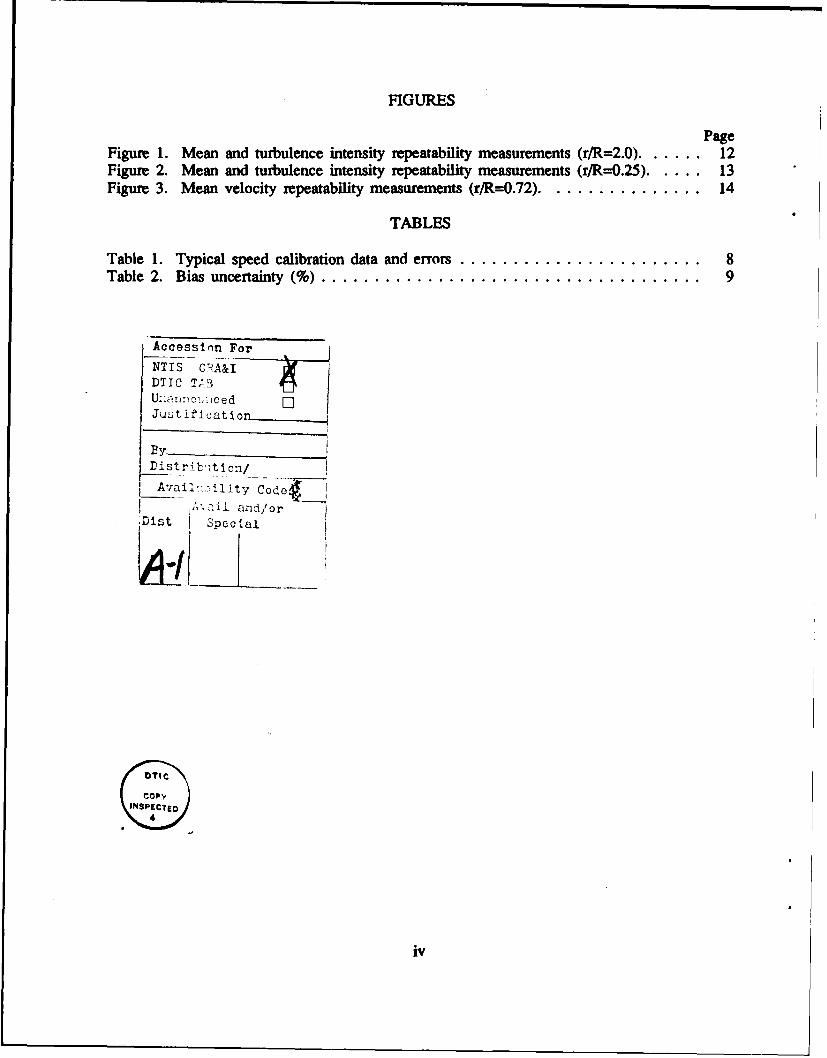
PageFigure 1. Mean and turbulence intensity repeatability measurements (r/R=2.0) ...... 12Figure 2. Mean and turbulence intensity repeatability measurements (r/R--0.25)..... .13Figure 3. Mean velocity repeatability measurements (r/R=0.72) ................ 14
TABLES
Table 1. Typical speed calibration data and errors .......................... 8Table 2. Bias uncertainty (%)..................................... 9
Accession For
NTIS C 'A&I
DTIC TABU:1On)oi.-icedJust i f I at ionL
By
Avail'i-lity' Code-A; cal aid/or
'Dist Special
iv

NOTATION
direction cosine between coordinate direction k and probe direction j
E bridge voltage
k yaw constant
L model length
Q, effective cooling velocity sensed by sensor m
AP pitot-static dynamic pressure
r probe position radius
R model maximum radius
T temperature (0C)
TI turbulence intensity
uk component of instantaneous velocity vector in direction k of referencecoordinate system
U,V,W mean velocity in three-component directions (x, r, 0)
UWrTA total velocity vector magnitude
Vi instantaneous velocity component along (parallel to) sensor j
x axial distance measured from model nose
Cc pitch angle
+ instantaneous angle between total velocity vector and normal to sensor
p density
0 angle between sensors, or probe circumferential position
Sstandard deviation
Subscripts
s sensor
c calibration
• experiment
ref reference value
v

ABSTRACT
The uncertainty associated with measuring the three-componentvelocity for the DARPA SUBOFF experiments has been investigated. Biasuncertainty due to temperature variation, probe alignment, analog to digitalconversion, speed calibration and angle calibration resulted in an overall 2abias uncertainty of * 2.21% for u/U,,, ± 2.28% for v/U,w, and ± 1.79% forw/U,,. Precision (random) 2o uncertainty depended slightly on turbulenceintensity levels. For low turbulence intensity levels (TI - 0.5%), precisionuncertainty was ± 0.04% for u/Uref, ± 0.04% for v/U,,, and ± 0.06% forw/U,,. For high turbulence intensity levels (TI 4%), precision uncertaintywas ± 0.28% for u/Uref, ± 0.16% for v/U,,, and ± 0.20% for w/U,.
ADMINISTRATIVE INFORMATION
The work described in this report was funded under the Defense Advanced Research
Projects Agency (DARPA), Task Area S1974-030, Program Element 63569N, and
performed under David Taylor Research Center (DTRC) work unit 1-1542-123.
INTRODUCTION
Experimental velocity measurements were performed using hot-film anemometry to
assess current Computational Fluid Dynamics (CFD) capability for the DARPA SUBOFF
Project (Huang et. al, 1989'). Three components of velocity were determined from
voltages of the hot-film sensors. This involved analog to digital data conversion and
acquisition, speed and angle calibration, temperature compensation, and real-time data
reduction. To establish a level of confidence in these velocity measurements, it was
necessary to estimate the experimental uncertainty. Bias uncertainty estimates were found
from perturbing data reduction equations with estimates of individual uncertainty (e.g.,
temperature). Precision uncertainty estimates were found from statistical analysis of
repeated measurements.

EXPERIMENTAL FACILITIES
The David Taylor Research Center (DTRC) Low Turbulence Wind Tunnel (LTWT)
was used for calibration measurements and the DTRC Anechoic Flow Facility (AFF) was
used for experiments presented in this report. Velocity measurements were normalized
with a reference velocity measured in the free-stream at an axial location x/L = 0.88,
where preliminary measurements showed a minimal radial velocity gradient. A Datametrics
Model 1174 Barocel Electronic Manometer with a 10 mm Hg pressure transducer was used
to measure the dynamic pressure of two pitot-static tubes located at the reference plane.
An Omega 5830 thermistor was used to measure free-stream temperature. A TSI IFA-100
Intelligent Flow Analyzer with Model 150 anemometers and Model 157 signal conditioning
was used with a TSI Model 12991-20 three-component hot-film probe to measure the
instantaneous velocity components. Data from the Barocel manometer and the
anemometers were collected using a Unix based Masscomp 5420 computer with 16
channels of 333 khz aggregate analog to digital conversion. Compumotor stepper motors,
controlled over the IEEE-488 bus, were used to position the probe during both calibration
and experimentation.
Software, written in the "C" programing language, was developed on the Masscomp
for calibration, data acquisition, probe traversing, data reduction, data archiving, and initial
plotting of velocity (See Appendices A through C).
VELOC1TY MEASUREMENT
HOT-FILM ANALYSIS
The total velocity vector, UmoA,, can be related to the effective cooling velocity,
Q., (Hinze (1975)2):
2

Q2= U2,,, ( cos2 * + k' sin' ) (1)
For three-component analysis, the effective cooling velocity as a function of
instantaneous velocity along each sensor, Vi, is (Lakshminarayana, 19823):
3
Q 2 = 1 V2j ( k.1 cos 2 O. + sin Om) (2)
where k is the yaw constant.
For orthogonal sensor analysis, 0., = 900 for m j, & e.j = 00 for m = j, and
3
I a2 . - 1 (3)k=1
where ak are the direction cosines between the probe coordinate direction and the sensor
directions, and:k2 1 1
Q2 = I k' 1 V2, (4)1 1 ki2
where k=k,=k=k3 is assumed for identical sensors.
The relationship between coordinate system velocity, Uk, and velocity along each
sensor is3
To relate the anemometer output, E1a, to the response of the sensor, a variation of
King's law was used:
U,.* = A + B E2. (6)
Separate speed and angle calibrations were performed. For speed calibration, U =
U., V=W =Oand:
Uw.L = A + B E2. (7)
3

A series of voltages for various reference velocities were obtained. An iteration scheme
using a polynomial least square fit on 1/n was performed to obtain n, A, and B.
For angle calibration, the probe was rotated through a variety of yaw and pitch
angles in the uniform free-stream of the LTWT. At each position, three components of
velocity were known (determined from reference velocity, yaw and pitch angles). Using
the speed calibration found in (7), and substituting into (4), the cooling velocity was found:
Q2 . = (A+B E2)2 [ 1 + (k2 - 1) aW, ] (8)
Once Qm was calculated, V, was determined from (4), and then uk was determined from
(5).
From a set of possible direction cosines (satisfying restriction of (3)), the set which
results in the lowest difference between calculated U from (5) and actual velocity from
geometry was chosen to be the correct direction cosines.
TEMPERATURE COMPENSATION
Since the heat transfer from the sensor corresponds to velocity, a change in ambient
temperature results in a change in measured velocity. This can be compensated for if the
calibration temperature, T,, and the experiment temperature, Te, are known (sensor
temperature, T,, was set to 250 0C). From Buddhavarapu (1986), the corrected
anemometer voltage, E,, is calculated from the experiment voltage, E, using:
(T,-T c )EV = E-2 X×, T (9)(T, -T,)
Equation (9) can then be substituted into (8).
PlTOT-STATIC VELOCITY MEASUREMENT
Reference velocity was found from:
U = (10)
P
4

where Ap was the dynamic pressure from the reference pitot tubes. Density was found
from a fit of the thermodynamic properties of air given relative humidity, temperature, and
atmospheric pressure (Keenan et. al, 1980').
BIAS UNCERTAINTY
The bias uncertainty for three-component hot-film measurements can be divided into
five categories:
1. Uncertainty due to temperature.2. Uncertai- - due to probe alignment.3. Uncertau,,y due to analog to digital conversion.4. Uncertainty due to speed calibration.5. Uncertainty due to angle calibration.
The total most probable bias uncertainty can then be estimated as the root sum square of
the individual uncertainties.
TEMPERATURE UNCERTAINTY
The accuracy of the Omega thermistor is stated as ± 0.3 OC (± 0.2 0C (instrument)
+ ± 0.1 °C (probe)). The uncertainty in velocity obtained by perturbing equations (4), (5)
and (8) (using the method of Moffat, 1985') by ± 0.3 0C was ± 0.32% for u/Ur, v/U,,
and w/Ur.
PROBE ALIGNMENT UNCERTAINTY
The three-component probe traversing system was aligned with the longitudinal axis
of the model. Wake surveys were performed in planes normal to that axis. The measured
velocity vectors u, v, and w corresponded to components in a model coordinate system, x,
r, and 0. Since a measurable vertical deflection of the probe tip occurred when the
traverse was moved in the axial direction, alignment was performed at each of the four
5

wake survey planes. The traversing mechanism was adjustable in vertical (pitch) and
horizontal (yaw) directions.
For the two survey planes on the body, x/L = 0.904 an ' x/L = 0.978, the traverse
was aligned to rotate concentric to the model surface. Pitch of the traverse was adjusted
with measurements of the distance from the model to the probe at 0* and 1800; yaw was
adjusted with measurements at 90D and 2700. These measurements were performed using a
scale marked in 1/64 in. (0.04 cm) increments. The probe was measured concentric to the
model to within 1/32 in. (0.08 cm) using this method; alignment is estimated to be within
0.0260 of the model longitudinal axis.
For the two off-body survey planes, x/L = 1.04 and x/L = 1.096, the traverse was
aligned with the probe stem parallel to the longitudinal axis of the model. The pitch of
the traverse was adjusted at 00 using a line level on the probe stem. Previous
measurements using a small laser mounted on the probe stem showed this method accurate
to within 1/4 degree. Yaw of the traverse was adjusted to align the tube parallel to the
model centerline using a laser aligned along the pressure taps on the upper surface of the
model and a vertical rod alternately placed on the forward and rearward portions of the
tube. Alignment within 0.30 was obtained using this method.
Based on a nominal reference velocity of 147 ft/sec (44.8 n/s), the maximum bias
uncertainty in radial and circumferential velocity components due to misalignment in pitch
and yaw is estimated to be ± 0.5% for v/U, and ±0.5% for wIU,,. The bias uncertainty
in axial velocity due to misalignment is negligible.
6

PITOT-STATIC VELOCITY UNCERTAINTY
Measurement of reference velocity depends on temperature, relative humidity,
atmospheric pressure, and pitot-static pressure difference. The most probable uncertainties
for these variables are estimated as follows:
Temperature ± 0.3 °CRelative humidity ±5 %Atmospheric pressure ± 0.02 in HgPitot-static pressure difference' ± 0.01 mm Hg
The uncertainty in reference velocity obtained by sequentially perturbing Equation (10) by
each of these values and then root sum squaring was ± 0.1%.
ANALOG TO DIGITAL CONVERSION UNCERTAINTY
The analog to digital (A/D) converter resolution was 12 bits with a range from -10
to 10 volts. Therefore one A/D count was 20 volts / 4096 counts = 0.005 volts/count.
The anemometer bridge voltage gain was 6 and the A/D gain (on the A/D board) before
digitizing was 2. Therefore, to determine the effect of one A/D count on velocity, the
bridge voltage was perturbed by .005/12 = 0.0004 volts (typical reference voltages were
used). This resulted in ± 0.07% for uu/Uw, ± 0.13% for v/U, , and ± 0.12% for w/U,,.
SPEED CALIBRATION UNCERTAINTY
Anemometer voltages for various reference velocities with the probe normal to the
free-stream were obtained for the speed calibration. A curve fit to obtain calibration data
reduction equations was then performed (see equation (7)). Calculated values of U, V, and
W (as distinct from the true reference values, U=U., V=0, and W=0) were found by
inserting the anemometer voltages into the calibrated data reduction equations. An error,
For Barocel transducer: ± 0.05% of reading (8.6 mm Hg) ± 0.01% range (10 mm Hg)
± 1 A/D count (0.01 mm Hg)
7

-U.,)/U,,,, was obtained for each calibration velocity as shown in Table 1. The
uncertainty (2a) of these errors for a typical 10 point speed calibration was found to be: ±
2.12% for u/U,,,, ± 1.76% for v/U,, and ± 0.88% for w/U,,. These values were then root
sum squared with pitot-tube uncertainty to obtain speed calibration uncertainty of ± 2.12%
for u/U,,, ± 1.76% for v/U,, and ± 0.88% for w/U,, (pitot-tube uncertainty had
negligible effect).
Table 1. Typical speed calibration data and errors.
CALCULATED REFERENCE ERRORU V W U., (U-U) /U., V/U W/U
ft/s ft/s ft/s I ft/s I
69.24 -0.67 -0.03 68.95 0.42 -0.98 -0.0494.38 -0.06 0.03 96.41 -2.10 -0.07 0.03
119.03 0.56 0.06 117.68 1.14 0.48 0.05125.94 0.90 0.22 124.17 1.43 0.72 0.18
130.66 0.93 0.41 129.89 0.59 0.72 0.31136.84 1.19 0.29 136.35 0.36 0.87 0.21140.89 1.34 -0.49 141.54 -0.46 0.95 -0.35145.82 -0.81 -1.57 146.99 -0.80 -0.55 -1.07152.86 -1.08 0.76 152.41 0.30 -0.71 0.50
155.96 -2.37 0.34 157.41 -0.92 -1.51 0.22
0 1.06 0.88 0.44
ANGLE CALIBRATION UNCERTAINTY
Uncertainty in angle calibration can be calculated similar to the method used for the
speed calibration. However, uncertainty increases with increasing flow angle. For flow
angles 250 or less, 2a was found to be ± 2.08% for u/U,, * 3.60% for v/U,T,, and ± 3.80%
for w/L,. However, flow angles greater than 100 were not observed in the turbulence
data. Therefore, 2a for this range was found to be ± 0.52% for u/U,,, ± 1.30% for v/U,,,,
and ± 1.42% for w/U,,.
8
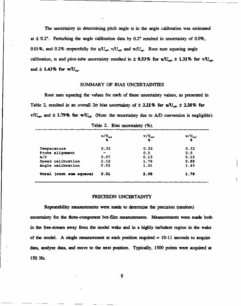
The uncertainty in determining pitch angle a in the angle calibration was estimated
at ± 0.20. Perturbing the angle calibration data by 0.20 resulted in uncertainty of 0.0%,
0.01%, and 0.2% respectfully for u/U,, v/lJ,.,, and w/U,,. Root sum squaring angle
calibration, a and pitot-tube uncertainty resulted in ± 0.53% for u/U,,, ± 1.31% for v/U.,
and ± 1.43% for w/U,,.
SUMMARY OF BIAS UNCERTAINTIES
Root sum squaring the values for each of these uncertainty values, as presented in
Table 2, resulted in an overall 2y bias uncertainty of ± 2.21% for u/U.,, ± 2.28% for
v/U,, and ± 1.79% for w/U,w (Note: the uncertainty due to A/D conversion is negligible).
Table 2. Bias uncertainty (%).
U/U,,f V/Uw/,
Temperature 0.32 0.32 0.32Probe alignment - 0.5 0.5A/D 0.07 0.13 0.12Speed calibration 2.12 1.76 0.88Angle calibration 0.53 1.31 1.43
Total (root sum squave) 2.21 2.28 1.79
PRECISION UNCERTAINTY
Repeatability measurements were made to determine the precision (random)
uncertainty for the three-component hot-film measurements. Measurements were made both
in the free-stream away from the model wake and in a highly turbulent region in the wake
of the model. A single measurement at each position required - 10-11 seconds to acquire
data, analyze data, and move to the next position. Typically, 1500 points were acquired at
150 Hz.
9

Figure 1 shows mean and turbulence intensity versus time at one spatial position
(r/R = 2.0, x/L = 1.096) in the free-stream (TI = 0.5%) for thirty points taken
consecutively. Mean and 2a of the mean velocity were 0.955 ± .04% for u/Uref, 0.012 ±
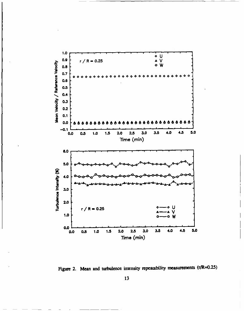
0.04% for v/U,,, and -0.011 ± 0.06% for w/U,,. Figure 2 shows profiles for one spatial
point in the turbulent wake (TI = 4%, r/R = 0.25, x/L = 1.04). Mean and 2a of the mean
velocity were 0.653 ± 0.28% for ufUref, 0.003 ± 0.16% for v/U,, and -0.013 ± 0.20%
for w/U,.
Figure 3 shows mean velocity versus time at r/R = 0.72 and x/L = 1.04. The time
involved (= 30 minutes) is representative of the time required for a typical constant radius
wake survey. In the time between 8 and 25 minutes, the probe was moved to different
radius and 0 positions and then returned to r/R = 0.72 and 0 = 00. Mean and 2T of the
mean (80 points) velocity were 0.938 ± .16% for u/U,,d, -0.008 ± 0.06% for v/U,,a, and -
0.020 ± 0.04% for w/U,.,. This is an indication of the repeatability of one single velocity
measurement over the typical time of one survey and the repeatability of the traverse in
returning to the same position.
SUMMARY
Bias and precision uncertainty associated with three-component hot-film velocity
measurement have been investigated. Bias uncertainty was found to be primarily dependent
upon speed calibration. Other significant factors were: angle calibration, temperature, and
probe alignment. This resulted in 2a bias uncertainty of ± 2.21% for u/U,, ± 2.28% for
v/U , and ± 1.79% for w/U,. Precision 2a uncertainty was found to have a slight
dependency upon turbulence intensity. For low turbulence intensity levels (TI - 0.5%)
precision uncertainty was ± .04% for u/Uref, ± 0.04% for v/U,,, and ± 0.06% for w/U,.
10

For high turbulence intensity levels (TI 4%), precision uncertainty was ± 0.28% for
u/Uref, ± 0.16% for v/U,,, and ± 0.20% for w/U,,. Therefore, bias uncertainty was
found to be the dominant uncertainty.
ACKNOWLEDGMENTS
The authors would like to thank Dr. Mark Coughran for his excellent three-component hot-
f'dm data reduction summary.
11

0.9
0.8 Ur 0. rR 2.0 AV
.7
C 0.6
*.0.4
~0.3
~0.2
S0.1
~0.0
0.0 0.5 1.0 1.5 2.0 2.5 3.0 3.5 4.0 4.5 5.0
Time (m in)
0.7
0.5
10.41
O0.3
~0.2 -. Ur/ R -2.0 A-A V
0.1 -0-O W
0.0 L- , . - - . - . -I
0.0 0.5 1.0 1.5 2.0 2.5 3.0 3.5 4.0 4.5 5.0
Time (min)
Figure I. Mean and turbulence intensity repeatability measurements (r/R=2.O)
12
1.0
0.9 r/R-0.25 A V
0.8 oW
> 0.7
i 0.6
0.5
0.4
0.3
1 0.2
o 0.10.
0.0 66666666666666866 66 6 6 866
o.o o. 1.o 1.5 -0 2.5 3.0 3.5 4.0 4.5 5.0
Time (min)
6.0
5.0 . , -* *• , *,.- ,,
4.0 oo~o.
3.0
52.0
r/R .25U1.0 0-0 W
0 .0 1 ' " " '
0.0 0.5 1.0 1.5 2.0 2.5 3.0 3.5 4.0 4.5 5.0
Time (min)
Figure 2. Mean and turbulence intensity repeatability measrmets (r/R=0.25)
13

0
>
4 0CO
If
CCD
40019~lA eoue.9eJGe98 / IPOleA uD9e4
Figure 3. Mean velocity repeatability measurements (r/R=O.72)
14
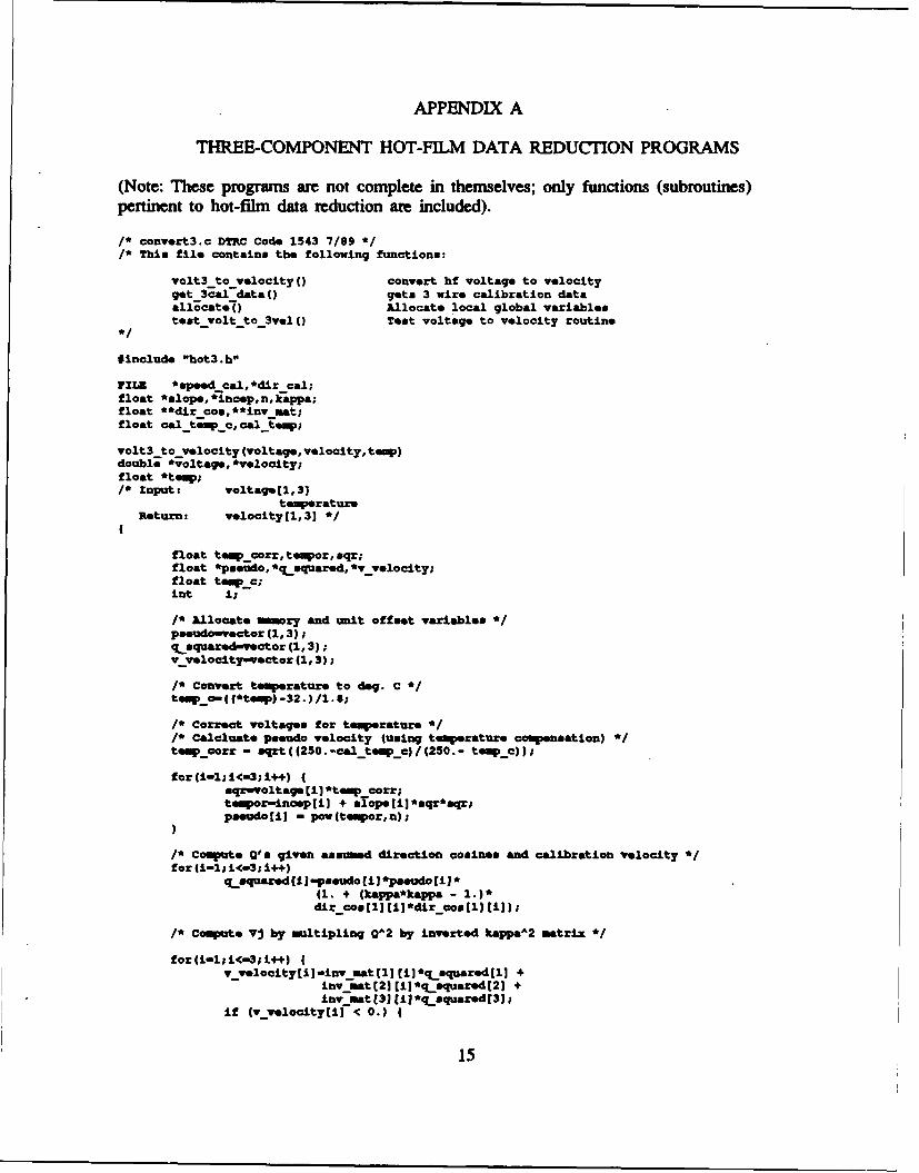
APPENDIX A
THREE-COMPONENT HOT-FILM DATA REDUCTION PROGRAMS
(Note: These programs are not complete in themselves; only functions (subroutines)pertinent to hot-film data reduction are included).
/* convert3.c DTRC Code 1543 7/89 */* This f ile contains the following functions:
volt3 to velocityoC convert hf voltage to velocityget -3cal data() gets 3 wire calibration dataallocat,4() Allocate local global variablestest-volt to 3val () Test voltage to velocity routine
*include "hot3.h"
VILE *epeedcal, edir cal;float *slope,*iaoep,n,kappa;float **dir cos, **inv mat:float cal tempc, cal-temp;
volt3_to-velocity (voltage, velocity, teW)double *voltage, evelocity:float *tes;/* Input: voltage[1,31
temeratureReturn: velocity[1,31 *
float teW_!car:, tempor, sqr;float epseudo, *qsquared, Cv velocity;float te.Fc;mnt i;
I' Allocate mawry and unit offset variables C
pseudo-vector (1,3):qaquared-vector (1,3);vvyelocity-vector (1,3):
/* Convert toe"erature to dog. C C
/C Correct voltages for temperature C
/* Calaluate pseudo velocity (using temperature compensation) CteW. cor: - sqrt((250.-cal tempc.)/(2O.- teWc));
for(i-1;i<-3:i44) (sqr-voltage (i1 Ctep corr:tempor-inasplil + alopetil 'aqr'sqr;pmeudojiJ - pow(tepor,n);
/* Compu e Q's given asnud direction cosines and calibration velocity Cfor (i-li<-3: 14)
qLsquared fi J-pseudo iJepaeudo (ii*(1. + (kappaftappa - 1.)*dir comsl]i) ( dir-cos~lj (i):
/* Copute Vj by multipling 0A2 by inverted kappaA2 matrix C
for(i-1;i(-3;i++)v-velocityli-invmat(11 (iiCqsquaredtlI +
invmat([21(Ij~qsquared(2j +Inv ist (3) (11 Cq-quared (3);
if (vvelocittj j< 0.) 1
15

printf(s** Negative V *
V volocity[ij- -l.*v-velocity(ij;
v-vlocityliJ-aqrt Cv velocity (ii);
/* Compute u,v,w (computed velocity in probe coordinates) given directioncosines and V'. *
for (i-i; iC-3; i++)velocityliJ-dir-con [i l1*v velocitytl] +
dir -cos[ij [21*vvelocity[2] +dir7 coon [i) (31*vvolocity[31;
volocity[3J a-l-.;
/* Deallocate, memory *free-vector(paeudo,l,3);fre vector (qasquared, 1,3);free vector(v_vlocity,l,3);
/* Function to allocate mory and unit offsmet variables(called once upon entrance to main program)NOTR.Z These variables are local to this file *
allocate()
alope-vector (1,3);incep-voctor(1,3);dir-co&-vmatrix(l,3,l,3);Inv-mat-matrix(l,3,l,3);
/* Read in direction cosines and speed calibration data *get_-3cal -data()
mnt i,j;float S'in;char file nam*141I;.printf (filenam, /hom/blanton/f/caldata/.pdcal. bs",probe _num);speed _cal-fopen(file -nam, "r");if (lapeed_ Cal)
printf("\n*** %o could not be opened\n", fils-name);exit 0;
fecanf (speed cal,wtf %fw, Sn, Seal temp),printf(nn 46.f Calibration temp- %4.lf",n,cal-tmpl;cal temp o--(cal temp-32. ) /1.S9,
for(i-l;i<w3;i+4) {fscanf(npeedcal,w%f %f",AslopeI),Sinoep[iI);printf("\nalope- %6.4f inoep- %G.4f",8loP*EiJ ,inoep[iJ);
printf ("\n")fclose(.peedcalI);
.printf (file-nam,"/bom/blanton/hf/caldata/dircoa .a" ,probe num);dir cal-fopen(file name, "r");if (IdIr cal) (
printf(\n*** %a could not be opened\nw, file-name);exit ()
fscanf (dir cal, "%f", Skappa),for (i-l; i<-3; i4+)
fecanf (dir cal,Otf %f %f",&dIr-cos[lj(1,SdIr -costiJ [21,sdtr7 con (iJ (31 )
for (1-111<-3;i++)
16

for(j-l;j<-3;j++) (priratf("'b6.4f ",dir cog (iJ ii
)printf("\n");
feos..(dir cal.);1* compute Iffectivenase Matrix (Kappa squared) and invert *kappa,_matrix (kappa,imv-mt);
/* Function to toot voltage topvelocity routine *test -volt to 3vel 4)
double voltage[4),vel[4J;float temp;
printf("\n\nlnput 3 values of voltage. )
mcanf("tlf %If %lf',avoltaqe~lJ ,avoltage[21 , voltage(31);printf ("\Znput experiment temperature. )
-c ("f, &tep) ;printf("\nRl-*6.4f 32-%6.4f Z3-%6.4f",voltage~lj,voltage(2],voltagGE33);volt3 to velocity (voltage, vel,Gtemp);printf("\nU velocity - lbf\nV velocity - *f\nw velocity -4~nfv.1(11 ,vel(2] ,velt3j);
1* matrix.c DTRC Code 1543 7/99 *1* This file contains.
kappa matrix() compute effectiveness (Kappa A2) matrixmat-inv( 0Invert 3X3 matrix ~
*include, Obot3.b"
/* Compute effectivness matrix (kappa **2) *kappa matrix (kappa. mv)float **Lnv,kappa;
float **k mtrix;mnt i,j;float c2tb,a2tb;char tst[S1j,
k matrixematrizil, 3,1,3);
for(im2;i<m3:i.4)4
If (i I- j)2tb - 0.;
if (i - J) c2tb - I.;if (I - J) a2th - 0.;"mtrixti jj - kappa~kappa*c2th + s2th;
1* Invert kappaA2 matrix *mat mvy (kmtrix, mv);
/* Pree memtory *1free matrix 4k matrix, 1,3,1,3);
/* To invert a 3X3 matrix *1* mat: 3X3 input mastrix
mnv: 313 inverted matrixdets determinant '
mat Inv (mtat, mvw)fjloa&t -*=at, *mflv,
17

float dot;int i, J;
dot - matjl)[1j*mat(2[2J*Uatj[31 mat~ljjlj*mat[21(31*mat[3)J21
-mat~lj(2I*.at(2I(1J*mat(3j(31 + mat~l1(2]*mat[2jj3)*Uatt
3i (11
+mat~l1 (3j*mtj2] lI*matt3i (2] -matti] 31*mat[21 (21*mat(31 (11;
inv(l1lI) - (uat(2](2103atE31(31 - .t[21(3j*matE31(2J) /dot;
inv(21 (21 - (mat~ll(ll*mat(31 (3] mat~ll(3J*mat(3j (1) / dot;
inv(3] (31 - (matjli (lJ*mat[21 (21 mat~l] (2j*uat[21 (i) /dot;
/* of f diagonal elements are transposed when calculated '
inv(11 (2] - -l*(matjl1C2]*mat[31(S1 - mat~lI(3j*=at[31(2J) / dot;
inv~l] (31 - (mat[l] (21*matE21 (3] - mat(1] (3]*mat(2] (21) / dot;
inv(21 (11 - .l*(mat(21(l1*uat[31 (3j - mat[21(31*mat(31111) / dot;
inv(21 (31 - -l*fmat~l1(l]*3at(2jj3j - mat~lj(31*mat[2I~li) / dot;
inv3(31l] - (.at[21(1]'mat[3112 1 - mat[2](21*30t[3j~lJ) /dot;
inv(31(2J - -1*(mat(l1i1l*mat(31[21 - mat(l1(21*aat[31111) /dot;
1* stat.c DTRC Cod* 1543 7/89 */* This fil1e contains the following functions:
fftatsQ); Compute man velocity, rms velocity,and Roynold's stress
Global varisbles-
input:velocity (mum datapoints] (3] instanteous u,v,w velocitynum _data-points number of data points
Output:moan(1,31 man velocityrmo[1,31 ras velocityretrosall,3] Reynolds stress
ratressilj (-u'v') (avg)retrsss(21 (-u'v'?)rstroso[3] (-V'wp)
#include "bot3.h"
stats i()
mnt i'J;double *um2
/* Allocate memory 0
summdvoctor(1,31;sum2-d. tor(1,3);
sum(i1) -0;
for (i-li <-num datapointm; 14+)for(j1f;J<m3;j++) J
SuMIJi 4- velocityl(1 11
for (1-1;i<-3p 1+4)mean (iI-sum(iI /num data~poiflts;
for(i-;II<-3;i++)sumi1 -0;som2 (11-0;
for (1-1:1<-mum datapoints; 14+)(
18

RUMjJ) +- (velocity[i)J (11meanhjJ)*(velocityli) [J-meanhj]);
au=2[lJ+- -1.*(velocityliI(l]-man[lJ)*(velocityli(213aean(2J);sum2[2]+- -l.*(velocityri)rl]-manrll)*(velocityci]c31-mean[3I);sum2[31+- -1.*(velocityfi) [2]1man[2J)*(velocity[iJ [3J-mean[3J);
for (i-l; i<-3;i++)rmslij - sqrt(mumjij/numkdatapointm);ratress (i)-sum2 (±1/numt dtapoints;
/* Deallocate memory *free-dvector(mum,l,3);free-dvector(sum2,l,3);
/* metup.c DTRC Code 1543 7/89 */* This file includes the following functions:
set-constants () Reads various enviornuental constants from file"constants.dat", prompts for corrections, setscurrent local variables and writes correctionsback to file
get _densitf() Returns density (slugs) given expeiriment temperature,atmospheric pressure and dew point temperature
aff-vel() Returns reference velocity given pitotpressure difference and slugs
ltwt vel () Returns reference velocity given pitot pressuredifference, experiment, temprature, relativehumidity and atmospheric pressure
#include Obot3.hwFILE *contants,*speed cal;
float pressure-atm;float slugs, tmp-ew;float rel hum;
set -constants()
char temp[Sl), test (S1);
/* input constants from file 5
conatants-fopen ("/hom/blanton/hf/constants/constants .dat", r+");If (Iconstantm) (
printf("\n*** /hf/constsnts/conatants.dat could not be opened ***\nI');emit 0;
fscanf (constants, *Ws, tep),if (tolower(temp(Oj I 'in'I) probe .type w XW1AN;if (tolower(tempCOl) - It') probe-type - TRIWIRN;if (tolower Item (0OJ) I= IV' 68 tolower(temp(O]) IM It')4
printf ("\n Probe type variable not oorrect\n");eZito4;
fscanf (constants, "%",probe-nim);facanf (constants, "Os",temp);if(tolower(tmp[OJ) - 'a') wind tunnel - ArI;if (tolower(tmptOI) - '1') wind tunnel = LTWT;if(toower(tmp(OI) I= III && tolower(temp(O]) I= 'a')4
printf (O\n Wind tunnel variable not correct\n");
fscanf (constants, %f", Spressure-atml;
if (wvind turael - A"7 )
19

printf("\n\t\tYou are using AFF wind tunnel option\n");fscanf (constants, "4f", 6temp de*w);
if (wind tunnel - LTWT)jirintf("\n\t\tYou are using LTWT wind tunnel option\n");fsc-anf (constants, "%f", Grel hum);
do
/* Print constants to screen ~if (probe type - KR)
jrintf("\n\nl. Probe Type - ]MRS");if (probe type, - TRrWIRS)
printf("\n\nl. Probe Type - TRIWIRS");printf("\n2. Probe Number - Ws,probe-nun);printf("\n3. Atmospheric pressure - %5-1f in. Hg",pressure-atla);if (wind-tunnel - UT %.fdg "tm
printf("\n4. Dew Point Temp - 4l ogVepdew);if (wind tunnel - LTWT)
jrintf("\n4. Relative Humidity, - %4.lfk%",rsl hum);
printf("\nq. Continue and Savo\n\n: )
gets (teat);
switch (tet(OJ)
/* Change constants (if necessary) Ccase Ill:
do{printf("\nanter Probe Type\n\tx - X rilm\n\tt - 3 Component\n: )scanf("ba",telhp);if(tolowor(temp(OI) - 'x') probe-type - XWXhB;if(tolower(temp(OI) - It') probe type - TRIWINI;
)while (tolower(tmp[01) I- 'x' && tolower(temp[OI) I- It');
getchar o; /* Get carriage return left over from scanf? *case '2':
printf("\n\n\tl96 -Three Component Serial #91196");printf("\n\tt9 Three Compnent Serial # 91069"1;printf("\n\ta5O -Two Component Serial*?")printf("\n\tx~l -Two Component Serial*??)
printf("\unter Probe Humber: )acanf ("%s",probe nun);getchar 0; /* Got carriage return left over from scanf?7~break;
came, '3':printf("\nanter Atmospheric Pressure (in. Ug): )scanf(M%f",SpresmsureatM);getchar o; /* Get carriage return loft over from scanf? *break;
case '4':if (wind tunnel - LIP)
jrintf(-\n~nter Dew Point Temperature (deg 7): )acanf (OWf, &temp dew);
if (wind tunnel - LTWT)jrintf(-\n~nter Relative Humidity (4%): N);scanf ("Wf, &rel hum);
getchar 0; 1* get carriage return left over from mcanf? *break;
came, 'q':/* save constants to file 0
rewind (constants);if(. .. boo type - IWMR
11printf (constants, "WrINn");if (probe type - TRIWIRN
Ep~rintf (constants, "TRZWIR\n");fprintf (constants, "%\n,probe-nun);if (wind tunnel - AM )
fprintf (constants, "LII\n");fprintf (constants, "%5.2f\n",pressure atm);
20
fprintf (constants, "%4.lf\n", tem dew);
if (wind tunnel - LTWT)FPrintf (constants, "LTWfT\n");fprintf (constants, "%5 .2f\n",pressure atm);fprintf (constants, "%4.lf\n",rel-hum);-
fclose (constants),break;
while (test(0)It- 'q');
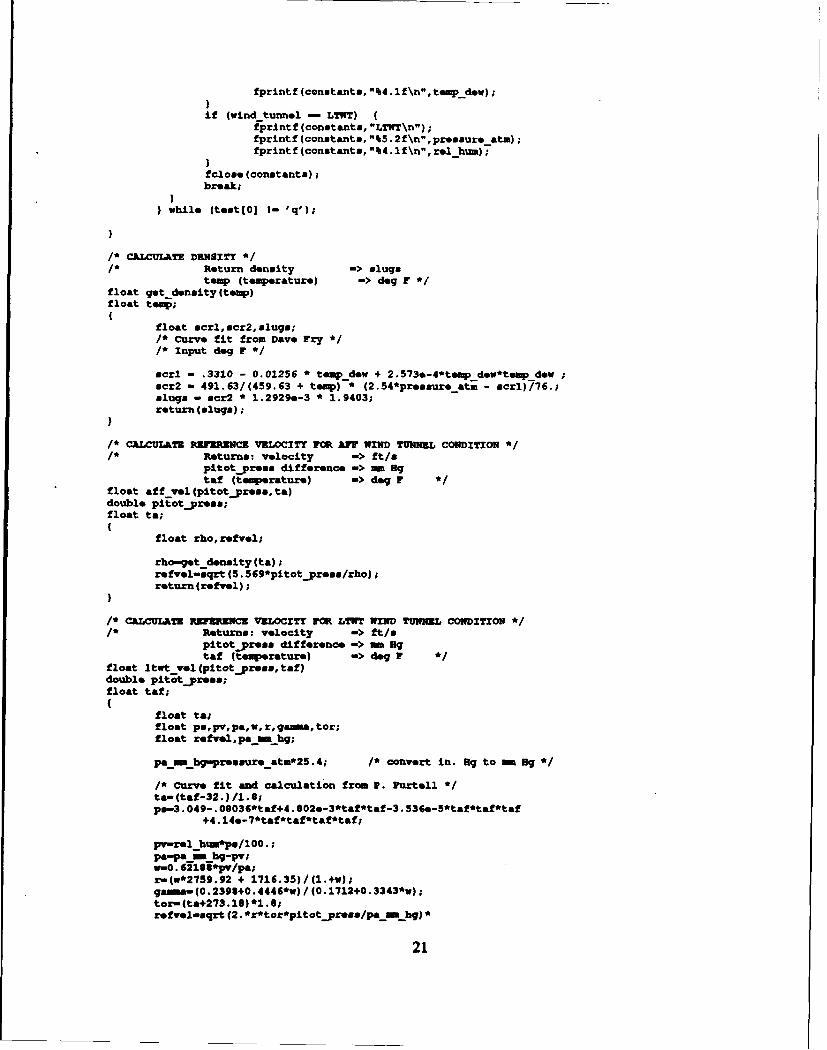
/* CkLCULKTE DENSITY *1* Return density ->slugs
temp (temperature) ->dog F *float get density (temp)float teow;
float sel, scr2, slugs;/* Curve fit from Dave Fry */* Input deg F */
scrl : .3310 - 0.01256 * temp dew + 2.573*-4*temp dev*tesspdewscr2 -491.63/(459.63 + temp) * (2.54*pressure atm - scrl)/76.;
slugs - scr2 * 1.2929*-3 * 1.9403,return (slugs) p
/* CALCULATE REFERENCE vaLociTy FOR A"V wIn TuWNZL CONDITION*/1* Returns: velocity ->ft/s
pitotpress difference => Hg
taf (temperature) ->deg F *float aff vel (pitotpress,ta)double pitEotjpresa;float ta;
float rho,refvel;
rho-get density (ta);refvel-sqrt (5. 569*pitotpress/rho);return (reftel);
/* CALCULATE REFERNCE VXLOCITY FMR LTNT WIND TUNEL CONDITION *1* Returns: velocity ->ft/s
pitotpreas difference am - gtaf (temperature) ->deg r
float ltwt vol (pitot~presa, taf)double pitotpress;float taf;
float tatfloat ps~pv, pa~w, r. ga, tor;float refvel, painRhg;
pa~mhg-peesurs-at=*25.4; /* convert in. ag to Hg B /
/* curve fit and calculation from P. Purtell *ta-(taf-32. )/1.6,ps-3 .049-. 06036*taf+4 . 02.-3*taf*taf-3 . 36.5*taf*taf*taf
+4. 14e-7*taf*taf*taf*taf;
Pv-relbhum*p8/100.;pa-pa - hg-pv;W-0. 2166*jw/paprn(w*2759.92 + 1716.35)/(l.+w);gaa- (0.2393+0. 4446*w) / (.1712+0. 3343*v);ton- (ta+273 .16) '1. Sirefvel-sqrt (2. *r*tor*pitot-press/pa inbh) *
21

(I. +pitotpress/pa tUffn hg/4 . /gas=&n);return (refvel);
/* bot3.h *
#include <stdio.h>#include "/dtrc/include/nrutil .h"#include <moath.b>#define PI 3.1415926
/* Local parameters (note explicit typing):*
#define NULL 0*define BIZZOFGCA 1000#define NULLINTRAY -2
char probe num[41; /* Number for specific probe C
float **velocity; /* instant velocity array *short *raw mnt voltage; /* Raw data array C
float ref velocity; /* free stream velocity Cf
float Cinan,rm,*rstress; /* 3 deep vectors for each cbn.*//* float mean[4J,rms1:4j,rstrea&[4j; Clint numdatapoints; /* Number of points/channel to be taken C
enum { 1E , LThT ) wind tunnel,ean 4 IIRN , TRZWI.3 ) probe-type;mnt patbno; /* path number for III 48Cfloat man vel[300J (3] ,zms vel(3001 [31,re stress(3001 131.float plot rad1:300] ,plot theta 13001;mnt group nun array(30017Ant theta-address,rad address;/* struct sbared(
mnt num of~plotypts;char cominuentl1:891;char comnt2(8991float plot-rad[300J;float plot theta[13001;float man -vel(3001 [31;float rem vesl13001 1:1;float re sZtrs1300J1:31;
mtruct shared *data; *
22
APPENDIX B
THREE-COMPONENT HOT-FILM SPEED CALIBRATION PROGRAMS
(Note: These programs are not complete in themselves; only functions (subroutines)pertinent to hot-film speed calibration are included).
/* speedcal.c DTRC Code 1543 5/89 */
/* TMURE COMONENT HOFTFILK CALIBRATION MODULE
This program inputs 3 hot file voltages and 1 pitot tube voltagefor a range of tunnel velocities and computes slopes and intercepts for each velocity component*/
#include "cal.h"
float caltep[30];char file_name[413;FILE *calfile;double hf.voltageean[30] [3];double pitotvelocitypman 30];float avg cal-teup;
main ()
int done, i, J, ct;char check[8l] ,lchk[8lj ,tester[SlJ;double hfavgvolt[30]E3]; /* different from angoel.c */float pitot avg yel 301;float slope[3], incep[31;float get tWO; /* function declarations */float ltwt vel (), affvel ();float p volt;double sumf4j;float tempamx;float tempmin;
/* Allocate mmory and unit offset variables */hf volt-dmatrix (1, nframss, ,3);pitot-volt-dvector (1, nframm);/* Set enviorment */
sot constants ();
done - 0;
do (printf("\n\n\nRnter :\n\
\tl. Take Calibration Data\n\\t2. Analyze Calibration Data\n\\t3. Change Constants\n\\tq Quit\n\n\\t-") ;
scanf ("s", check);switch (tolower(check[0])) I
came I'l I/* let onviozment */set atod constants ();/* initialize IX 48 */init gpibo;/* Open output file */
aprintf (file name, "/boa./blanton/hf/caldata/rawspeed. %s", probe num);cal-file-fopen(file name, -r");
if (Ical file) (
23

printf ("\n*** Will create rawapeed. A\n",probe-nun);
if (Cal-file)printf("\nDo you want to append to rawapeed.%u? ft,probe nun);scanf("ta,tester);if(tolower(tomtor[Ol) I- 'y')
fclone(cal-file);fopen(file nam, ww");
fcloae(cal.-file);temp naxO;teupMin-lOO.;cnt-0;do
printf("\n Taking Data Run *%d\n\n",cnt + 1),got -ang vYoltage 0Cal teup~cnt] - get _tempo;printf ("\n Calibration Temprature is %f\n", cal teupcnt3);if (cal-templant] < temipjam) temp_ n-cal temp[Centi;if (cal-temp~ent] > temp max) tempmax-caf-tMIPjnt];for ( 1-0; i<-2; i+4)SUM~iJ - 0.;for (i-0; i<-2; i++)4
for (J-1; J<-nframs; J++) 4EMmEi +- bf-voltEJ]Ei+ll;
for i -0; i<-.2; 1++)hfavgvoltantj~iJ ft smni / nfraaeu;printf ("Voltage *%d is %bf\n",i,mum~iI /nfra:mea);
mum(0j - 0.;for (J-1; J<-nframa; J+4+1
sun[0J +- pitot-vlt[j);
p volt - ium[01 nframem;
if (wind-tunnel -LTUT)
pitot avg vol [anti -itwt-vel(p volt, cal-temp[cut));if (wind tunnel - MM)
pitot avg vel cantl-aff-vel(p volt, caltm cant));
sprintf (file-nam, /hom/blanton/hf/aaldata/rawspeed. 'a" ,probe mum);aal-file-fopen(file mano, "am);fprintf(aalfie,47i.f%0.5f%l.f'Il0.4f%10.3f\n",
hf vg yolt [anti [0],bf avg volt (antI [ii,hf ~avg volt (ant] (21,pitotavg vel (anti,aaltmpjntj);
f aloe cal file) ;printf ("\mVelocity is %f\n",pitot avg vol [nti),printf("\m\nuIt a to take next velocity or 'q' to continue:i)aaanf("*e",labk);amt++;
Iwhile (tolower(lcbk[01) I- 'q');
auM(0i-0;for(i-l;i<nt;i++)
IMMm[0+- Cal temp(iI,avg cal tem-u('j / (ant-1);primtf("r\nhvg temp-04.lf Kin Temp - 1%4.f tKax Temp - 4.lf\n",
avg cal_ temp. temipjam, temp max);break;
came '2':polycolve() Ibreak;
came '3':
24

set constants ();met-atod-constantao;
break;
case I : done - 1;break;
while (done - 0);
1* poly.c DTRC Code 1543 J. Blanton 5/09 *I* Program to determine best values of slope and intercept for each
probe *//CC**C* This file contains the following functions: CC*
poly-solve C) slope and intercept for 3-cowp probes
# include "cal.h"
ILE *cal file;
extern double hf voltagejmean [30) (31;extern float avg c-al-tmp;extern double pitot velocityjmean13OJ;mnt num of-calpoints;
poly~olveo(
float slopo(31 ,incepE31 ,coeff (33;float sum hf[33 , sumhf2(33, sum hfpitot (31;float xunDitot, mum pitot2;float pseudo vel (41;float errl,err2, err3;double sqr, tenpor;mnt i,j,test;float nim;char chock[SlJ;double top;float n-inv,exp;
get cal data );
num - u of cal-points;
/C LOOP FOR DZTZRHZNIIU T 58 1/169printf('\n exp #1 #2 #30);£or(exp-l.,expC-2.,exp +'- .05) 1
DnInv - 1. / ez;/C Zero out */forti-0; I<-2 ; i++)
sum hf (i3 0.;suim_hf2[ij 0.;sumL hf-pitot~i] - 0.5
aumpitot -0.; sumpyitot2 - 0.;
forfi-0; i<-2 ;i++) (for (J-0; $4nm of calpoints; J++)4
sum hf~i3+- (hf-voltage msanj1 Ci3*hf voltage meanci) (11);
sum hf2ti3 +- pov(hf voltage mean(~3 (ii,4.);sum hf..pitottil 4- pw(hf voltage mean~i) (iJ,2.)C
pow(pitot velocity mwaniji ,n inv);
for (J-0; j<numofyalponts; J++)4sum~pitot 4-pow (pitot velocity meanij,ninv);sum pitot2 4-pow (pitot velocityjmeant ji, (n mnv*2.));
25
/* Find Slopes and Intorcept. sfor(i-0; i<-2; i++)I
slope~i] a (sum hf...pitot(iI - uuinpitot*sum .hf(iI/Dum)/(sumhf2[i) - suni_hf(i]*suzmhf(il/lum);
incop (±1 - (smupitot-alope [±1 *smnRhf (1]) num;
top - sum hf..pitoti-mum,..hfri: emumitot Inu.;coeff~iI Z top * top /
((mum hf2(ij - umhfjil*mumhf~iIDWD)*(Mnmpiitot - umyitot*m lJitot/lu));
printf("\nexp-%5.3f Cooft - 466.4f %6.4f %6.4f-,exp, coeff (01,coeff (11,coeff[2J);
/* LOOP FOR DETUP)UNINE BEST 1/N *do
printf("\n\nlfter a value of n (U * (1/n): )
mcant ("%f", Gn mnv);n inv - 1. / n inv;/W Zero out */1for(i-0; J<-2 ; L+4) I
sum hf~ij 0.;mum _hf2[ij 0.;sum hfypitat[iI - 0.;
smmpitot - 0.; sumpitot2 - 0.;
for(i-0; i<-2 ; i++) 4for (J-0; J<nun. OfCalpoints; J++)
sum hf~iJ+- (hf -voltage mean [1] iJ*
bf voltage meeri~j]il);smmihf2[i) 4- pOW(bfvoltage_ eai[iJJ1
4.);muxm hfpitot~i) 4- pow(hf voltagmejamaljCl ±,2. )*
pow (pitot veloc1.ty...ean C1~1n );
for (1-0; (nuzmofcal.pOints; J++)smpitot +- pow(pitot velocitya(j)n...±v)mumpitot2 4- pow (pitot velocity aman (ii(n,±inv*2.));
/* Find Slopes and Intercepts *priatf("\nn - J53~"l/_n)printf(*\n slope zatercept Corr coeff\n");for(i-O; L<-2; i+4)(
alope~il - (smamhfpt tfi) - mpiot*mmhfi/lhm)/(mum b'f2[iJ - um _hf Ci *ammhf~iJfn=l);
incep(iJ - (aumpitot-olope~i)*en= hf~i1 I/a;
top - aiin.hf-pitot (11-mum -ht (ii 'mitot/nn.;coeff~i] - top * top /
((mum~f2iL] - mum bhf(i1*am bf~i)/tnua)*(aimptot2 - am pt~tot*gmm pitot/nuU));
printf("\n*%d %6.4f 'b6.4f %6.4f-,1+1, miope~il ,inoep(iI ,coeff (11),
do ( /* start of plotting do ~
printf("\n\nait n to try new value,'p' to plot or'q' to accept value% )meant ('m", check);switch (tolawer(cbeck(OJ)) I
case 'p': /* Plot data 'plot cmal (bf voltagejmean,
26

pitot -volocity mean,slope, incep,n inv,num of-calpoints);
printf("\nn - %5.3f~sn",1./ni- nv);printf("\n Slope Intercept Corr cootffn");for (i-O;i<-2;i++)
printf("\n#%d %6.4f Jk6.4f P64-i+l,alop.ei] ,incep~il,cooff~iI);
break;came 'q':
teot - 0;break;
case Inl"test - 0;break;
/* End of switch *while (test - 1); /* End of plotting do *
while (tolower(check[OiI I- 'q');
printf(\%nDo you want to save Calibration values to file? (yin) )acanf("Pke",chock);
if (tolower(checkfOJ) I-y'printf('\nOne more chance- Don't you really want to save?\n\
(Data will be forever lost) (yin) )acanf('%s",check);
if (tolower(checktOl) - 'y')
1* save slopes, intercepts, and n -inv to calibration file *
char file-name(37J;.printf (file-nam,"/houe/blanton/hf/caldata/apdcal. %a",probe-nut.);cal -file-fopen(file name, "w");if (Ical-file)
printf("*** to could not be opened\n",file name);exito;
printf("\n saving calibration file to .. .n\n", file nam);fprintf (cal file, "%5.3f %5.2f~n',l. /n inv, avg_ cal teW);for(i-0; i<-2; i++)
fprintf (cal file,"WU.4 %6.4f~n",slopefj ,incep~ij);folose (cal-file);
/* check calibration data *printf(wn Pseudo~l Pseudo*2 Pseudo#3 Eaf. Volocity\n");ext-l. /niLaw;for (iin0; inum of cal-Points; i4+)
for(JZO;f<3;j44) (sqr-hf voltage meanjiJ [ji,teqtor-incep~fJ + slope (1) *aqr*oqr;pseudo vol(13 - pow(tempor, (double) eap);
erri- (pueudo vol (03-pitot velocity_ meantil )/pitot velocity mean (ii*100.;err2-(poudo vol (11 -pitot velocitypman~i ) /pitot velocitymeanliJl 10.;orr3- (paoudo vel [2) -pitot velocityjmean[il)/pitot velocity meanCi) *100.;
printf("#i%10.4f*11. 4f%11.4f%11.4f%7.2f%7.2f~f7.2f~n,iL;,pseudo vel (03,peudo vel (11,pseudo vel (23,pitot velocity mean (II, rri, err2, err3)j
This file contains the following functions:i ***
get cal data () gets calibration data
#include Ocal.b"VILR *cal wel;WILE *conatanta, 'output;
27

extern int num-ofcal-pointa;oxtern double bf -voltagman30(31,extern double pitot velocityjaean[3O];extern float cal-tem[30J;extern char probe num[4 1;extern float avg_ cal toqp;float avgcal-tempc;char out file-name(411,
get cal-data()
int i;char dwny 1811;float scratch, ucratchi, acratch2;f loat t*Wcorr, cal-twWc;double sum;float t.omax-O;float tow-min-OO:
/* Find number of calibration points *char file-namo(41);sprintf (file-nam, u/hou/blanton/bf/caldata/rawspeed. %a ,probe num);cal vel-fopen(file name, "r");
if (tcal Vel) Iprintf(-~*** speodcal.las could not be openod\n",probe-num);exit 0;
num of.cal-point@=O;while (Ifoof (Cal-Vol))
fgeta (dumy, S,ca yel);numofc&apoints++;
fclose (cal vel);numof calpoints--;
1*fa velocity-dvector (1,numof-calpointe);alpha- vector (1,n niof calpointo);hf voltage-dmatrix (1, nm of calpointa, 1,2);error- vectora,num ofcaljoints);cal-toop- vector (l,num of _cal~points); ~
cal vol-fopen(file name, "ra);
for (i-0;icniMUofcalyoint;i1+0)f~canf(cal-vol"tlf %If %If %If *JfU
Whfvoltagejusazi(iJ(01,Whf votage .eai(iJ (11,
Gbf-voltage-eanjiJ (21,Apitot velocity mean (ii,
if (cal-tW*[i1 < teomi~n) to.- inn-cal tomp(i);if (caltempti > towax) temiuaz-cal-t.w(iJ;mum 4'- cal to~(i1;
falome (cal vel):1*avgc.al-teW-mm/nixof calpoints; C
/* use first tomerature as cal temperature and correct subsequent voltages to this Caltemperatulre */avg cal te.r-cal te~roj,avg cal tet- (cal tomp(01-32. )/l.9;
for (i-0;i<namof cal-pointN;i44) (caltmec - (cal tsW[iJ-32.)/2.S;tmwcporr - .qrt((250.-avgcaleWc)/(250.-calteWc));hf voltage mwan (ii(03 toWcorr;bfvoltageMeanh~jIJ 1 tompcorr;hifvoltagemeantiJ (21 *m t-corz;
printf("\nhvg toep-64.lf Kin Tomp 0 4.1f Max TeW - 64.lf\n",
28

avgcal tmp, tomp_pin, temp_max);
/* cal.h *1
#include <stdto.h>#include u.h>#include "/dtre/include/nrutil •h"#include <math.h>#define PI 3.1415926
/* Local parameters (note explicit typing):
#define MUM 0
#define SIZIOFCA 1000#define MULLINTRAY -2
int nframss; /* # of samples per channel */
char probe num[41; /* Number for specific probe */
float *alpha, *phi;double *pitot volt;
double **hf volt;
/* float qaIn,offset; /* anemometer gain and offset */
enum ( AFF , LTT ) wind tunnel;
int pathno; /* path number for Z1= 460 */
29

30

APPENDIX C
THREE-COMPONENT HOT-FILM ANGLE CALIBRATION PROGRAMS
(Note: These programs are not complete in themselves; only functions (subroutines)pertinent to hot-film angle calibration ame included).
/* Program angloo.c
J. Blanton May 1989 Code 1543 DThC
Based heavily on Pat Purtell' a 131G180FTH angle calibrationprogram May 1997 for a PDP 11/73
To estimate the angles the hot film elements make with the coord.system. Trial direction cosine data are read and iterated upon tominimize error.
Input files:angvel. (probef) angle and pseudo velocitiesdangle.dat trial direction cosines
*include "angcal.h"#include <stdio~hFILE *Cal;float STAKT KAPPA;float END KAPA;float XAPPAINC;float "*dir coo; /* dir cos(3J (3) 'float 'actua&l vel; /* actual vel(31 'float *V velocity; I' vvelocity[31 'float 'computodveYl; /' computedkvlocityC31 'float *qsquared; /* q quared(31, 'float **inv mat;float **err; /' computed - actual velocity (ang cnt](3] '/mnt 'kappa _dc, kappa js.jz ini*nuin ( YE , NO ) print-Vol;
main (
mnt i, J,k, dc num, kappa cnt, kappa num;mnt depth narn:float kappajamm;float 'avg eprr, 'avg aim sqr;float 'kappa var;float get _angle _file O,get _trial aumO; /' function declarations 'float get trial-Pco);char chOek (11;char file nme(411;
flot 'mm sPum sr /* dir. cos # where mmn error occurs '
char dumytS1J;print vel - NO; /' Disable printing of velocity values '
/* Detormine which probe to asem*set-Constants();
/' Read In Angle velocity data with alpha and phi angles '
/' Allocate momozy and unit-offset the matix for dir. cosinesdir cor-matrix (1,3,1,3);actual vel-veator (1,3);v velocityawector (1,3)1conputed~vel-vector (l, 3):1
31
qasquared-vector (1,3);inv mat-matrix(1, 3,1,3);
err-Zmtrix (1, 3, 1, angcnt);avg_ rr-vector (1, 4) ;avg mum aqr-vector (1, 4);aDin nuzn-ivector (1, 4),min-sum aqr-voctor (1,4);depth -num- (END _KAPPA, - SARTKAPPA) /KAPPA IkIC;kappa var-vector (1, 100);kappa dc-ivector (1,100);/* kappa, dc-ivoctor(1,30); *
/*Read in number of direction cosines and initial value of yaw constan~ts*/get trialnumo;
/* Loop through several kappa. *kappa nums-O;for (kappa-START KAPPA; kappa<-ZND KRPPA;kappa+- KAPPAINC)
kappa num+;
for (i-i; i<-4; ±4+)Mm sum smqr (ii-1000;
/* Loop through calculation for the number of direction cosines *for(i-1;i<-dc-cnt;i++) (
/* Read in a not of trial direction cosines *get trial coo(dir-co,i);
printf("\ntf Of Of Of Of Of Of Of Of\n",dir costli C1j,dir costli [21,dir comEl1 [31,dir m(a21lj,dir-coaf2j (21,dir com[2J [3],
_ircom[31 [l],dir cos[3J C2J,dir com(3] [3]);
comiate velocity i);
/* Compute statistics *forik-l;k<-3;k++) 4
ammquare (err (k), ang cnt, Aavg sum. aqz [k);1* ~statea rr~hj ,ang cnt, Lavg_ err~kj , avgsumsqr(kJ); *
if (avg_ mum mwqrjk] < uin-smmqr~k])min-sum sqrtk) - avg mum _sqr[kj;min num~k] m -
/* Compute average of averages *avg_ err[41-(avg rr[11 + avg_!orr[23 + avg eorrEMJ/3.;avg suwmmqr E41 - (avg mum qr [I] +
avg mum msqr [2) +avg mum msqr[13J) /3.;
if (avg_ mum sqr(41 < mineanm-qr[4))(min sum sqr(41 - avg mum qr(41;smnnuwTd - 1i
/*priatf("\nCos#%d EVvar-45.2f Vvar-45.2f Wvarw*5.2f Avg var-05.2f",i,avg sum asqr(1I,avg sum mqr(21,avg mum .qr(31,avg mum moqr[4)); *
)/* Und of dir. coo. loop */
/* print out minimum error* and coremponding direction cosines *printf("\n~axiom alpha - 1%4.1f Kappa - %6.4f\n",
alpha tang pntj ,kappa);
1* for(k-1;k<-3;k++) 4'1*printf(*\n~in avg var error#%d -03.3f dir. coo. *%d"
,k,xin mum &qrjkJ ,min nuwlkj); ~1* get_ trial cooldir com,min-num~k]), *I. print dc(air ca),
32

printf("\rdin avg var error % 5.3f dir, coon. Odn,min-sum-rnqr(4i,min-num[41);
got Itrial comn(dir corn, mm nuzn(4);printdc (dir-corn);
kappa _var(kappa _numi-min sum-nqr (41;kappada kappa _nun) -nn fu.(41;
)/* 2nd of kappa loop *
kappa mun~ain-i;kappa,_pin8TART KAPPA;kappa num-0;for (kappa-BART KAPPA; kappa<-ZND KAPPA;kappa+- KAPPAINC)
kappa num+-4;printf(\nKappa -*5.2f Min mean square error - 45.3f dir. corn. #*d"
'kappa, kappa _var [kappa _num],kappa _dc (kappa _num]);
if (kappa_var (kappa,_nun] < kappa,_var [kappa_nuzn_mini)kappa,_numn mkappa _num;kappa,_mm-kappa;
printf("\n\nKappa -%5.2f Min Min mean snquare error - %5.3f dir. corn. #%d",kappa mmi, kappa _var (kappa _nun~mini,kappada[kappa flu. .ini);
get-trial cor(dir-coa,kappa_dc~kappa _nun mini);printf ('\n");print dc(dir-corn);kappa-kappa min;
printf("\nDo you want to mave calibration values to file? (yin) )
scanf ('%e",chock);
if (tolower(chock(Oi) I- 'y') Iprintf("\none more chance- Don't you really want to savo?\n\
(Data will be forever lost) (y/n) )rncanf ("%r", check);
if (tolower(chock(Ol) - 'y')4uprintf (file nm,"/hom/blanton/hf/caldata/dircoa. %r" ,probe-nun);printf("\n~s", file-name);cal-fopen(file name, "w");
if (Ical) (primtf(m*** to could not be opened\n",fils-nam);exit 0);
fpzintf (cal, "%4 .2f\n", kappa mmi);
get trial coon(dir con, kappa_ dctkappa nun mini);
for (i-l;i(-3;i++) 4for(J-l;J<-3;j+4)
)fprintf (cal, "\n");
fcloso(cal);
/* Check calibration data Ccheck cal );
compute-7velocity (1)int i;
mnt J,k;if (print vel - ES)
pjrimtf('\nk&ppa - 4.3f*,kappa)sprintf(m\n &I pi Vol act cow rboorr )
33

/* Loop'through alpha and phi angle vol data computing errorsfor(j-l;j<-ang_cnt;J++) (
/* Compute U,V,W (actual velocity in probe coordinates)given alpha and phi */
actual-vel~l)-ref-ve1Cj1*coa(alphaj*PX/1BO.);actual volf2)-ref-VeblfjJ*ain(alphaljJ*PI/18O.)*
actual v.1(31- -1.*ref-vl(jJ*nin(alphaj*PI/19O.)*sin(phi[j1*PI/18O.);
/* Compute Ole given assumed direction cosinesand calibration velocity *
1* if (print vol - YES )(printf("\nkappa-%4 .3f",kappa);printf("\ndir-cool](ii- '%6.5f %6.5f
%6.5f",dir-cos~lJ[lj,dir-cos(l][2j,dir-cos~l)t3]);
for(k-l;k<-3;k++){q~aquared[k)-pseudo~jlkRI*pseudo(jJ (k] *
(1. + (kappa*kappa - 1)dir cos~lj (kJ*dir_co&[lj [kJ);
/* Compute Effectiveness Matrix (Kappa squared) and invert *kappa-matrix(inv-mat);
/* Compute V) by multipling 0^2 by invertedkappaA2 matrix *
for(k-l;k<-3;k++)vvelocity~kJ-invmat~kl (l1*qquared(lI +
Inv mat~kj[2J*q~oquarod[2J +Inv mat [ki (3j*q..squared(3j;
if (v-velocity~k] Z 0.) (printf("** Negative V *
alpha(jj ,ph 1 ,i)
v-vlocitylk]- -l*v velocity~k];
v velocity~kJ-aqrt (v vlocity~kJ);
/* Compute u,v,w (computed velocity in probe coordinates)given direction cosines and Vj'a a
for (k-l;k(-3;k++)computed val~kI-dir _cos~kI (l1*vvelocity~lj +
diLr cos~kj (23*vvelocity21 +dir cos~k] [31*v._.vlocity(3j;
1* Compute error (difference bowteen actualand computed velocity) *
for(k-l;k<-3;k+4) (err (kI [i-conmted -vel (ki -actual vel (k);
if (print vel - YES)printf("\n5.lf%6.lf6.2f%7.2f%7.2f%5.lf%7.2f%7.2f%5.lf%7.2f%7.2f%5.lf",
alpha~jI ,pbijI ,ref-eljj,actual vel(l,computed v.1(13 ,err(lj (13/actuaI -vol[l10.,actual vel[21,computed.vel(2J,err[21 (ii/actualvel~l100.,actual~vel(31,computed-vel(31,.rr(31 [:1/actual vel[11*100.);
/* end of alpha-phi loop *if (print vol. - YES
pri~ntf("\n");
check cal 0)
get trial corn(dir- coon, kapp&ac fckappa um .n minit
34

print vol - YEs;compute velocity (0);
print-dc(dir-con)float **dir corn;
int i,j;float sum;for (i-l;i<-.3;i++){
for(J-l;J<-3;j++)(printf("%6.4f ",dir-costiJljJ);
printf("\n");
printf(u\nSumA2 Col.");for(i-l;i<-3;i++) I
SUM. dir-cos[lJ[iI*dir-coa[ljtij +dir-cam E2J] J*dIr com[2] (i] +dir com(3J (i]*dLr-cos[3] ti];
printf(" *%d - %f",i,sum);
printf("%nS'um2 Row ;for(i-l;i<-3;i++) (
MAXIM dir-cos~iJtll*dir-comjijtlj +dir-com[i]C2I*dIr-com~ijt2j +dir cos~i] C3j*dir-cos~il t3];
printf(" #%d -%f",i, mum);
printf("\n");
mum-square (x, num, mum mqr)float *x,*m.Jmmqr;mnt num;
mnt i;double sm-Q;for(i-l;i<-num;i++)
sum 4.- xjiJ*x~ij;
*suxmqr - (float) sqrt(sum);
/* data in%.c DThC Code 1543 5/89 *This file contains the following functions: ***
get angle file 4) gets angle calibration dataget trial mum C) gets * of direction cosines
and kappa and keeps file openedto read itn values as needed
get trial ca ) Assign trial direction cosinesfrom temp array *
#include "angcal .b
/***** Read in Angle velocity data vith alpha and phi angles *
get_ angle file,4
Int i;char duy(61J;
/* Wind number of angle calibration points *char file namm(373;.printf (file-name,"/hom/blanton/bf/caldata/angvel. ts",probe _num);ag velrfopen(file name, "r");
if (tang vwel) Iprintf("*** AMGV3L.%s could not be opened\n",probe-nii);
35

exit ~
ang cnt-O;while (Ifeof(angvyl))
fgeta (dwuqy, SO, an; 1);ang-cnt++;
fcloae (ang v.1);an; ent--;
1* unit-offset alpha and phi (see Numerical Recipes In C p.15&16) *alpha- vector (l,ang_.cnt);phi- vactor(l,ang acnt);ref ve1- vector (l,an; ant);p..;udo-matrix(l,angcnt,1,3); /* Numerical Recipes matrix allocation *
angvel-fopen (filename, "r");
for (i-l;i<-angocnt;i++) {fecanf(angveol, "*f *f J*f Of *f %tf",&alpba[ij ,&phi [i] , aeudo [ii [lJ,
Gpsoudoti] (21, /* switched 2 and 3 *Gpacudocil (3],arof vol(u);
/* printf("\n%f %f %f %f %f %f",al7pha(i],phiti],peudo[il (13,p&*udo~i] (2],pseudo(ij [31,ref vel~i)); *
fcloae (an; vel);
/* Read in number of trial direction cosines and yaw constant *1* Keep file open to read in values as needed *
get -trial numo(
mnt i,j,dc flu.;
dangle-fopen("dangla.dat", "r");if (Id angle)
printf("*** DIAGL8.DAT could not be opened");exit 0
focant (dangle, "%d %f", ado_cnt, akappa);printf(*Itd Of\n",dcocnt,kappa);do _tewp-matrix (l,dc cat,1, 9);for(i-l;i<-dc cnt;i++)I
for (jzl;j<-9; +){focanf (kangle, O%f", dc-tmpij [JI);
facant (dangle, "Jd", Ida num);
fclose (dangle);
get trial co. (do, num)floa&t **dc-;mnt num;
/* Assign trial direction cosines from temp array '
nt J, k, dcnum, ent;cnt-lIfor(j-ljj<-3;j++) I
for(k-l;k<-3;k++)(dc(j j ki-dc teWp(nm (cat.+I;
/* movaqv.c DTKC Code 1543 5/699*/* This file contains
atata (v, n, avg, var) Cosmte, the vian and variance of a vectorof data (v)
36

where:v data array (usut be unit-of fset)n number of pointsavg mean value returned (must be pointer)var variance value returned (mus~t be pointer) *
#include 'nrutil.b"
stata (v, n, avg. var)float *v, *avg, avar;int n;Imnt i;float avgold;for(i-l;i<-n;i++)
if (i-1)4*avg..vllI;*var-O.;avgold- *avg;
if (1-2)*avg.-(avgold + v[21)/2.;*varO0.5*(avgold - v[21)*(avgold -v[21);
avgold- *avg;
if (il-i & iI-2)*avg - ((1-1)*avgold+v[iJ)/i;*var - ((1-2)* (*var) + (i-l)*avgold*avgold
- i*(*avg)*(*avg) +
v11J*v~iJ) / (i-1.);avgold - *avg;
/* angcal.b *
#include <atdio.h>#include R/dtrc/include/nnitil .h"#include <matb.h>*define, PI 3.1415926FILE *azgvel, *dkanqle,
float kappa;mnt dc cat; /* # of direction coo-counter ~mnt ang cnt; /* # of angle, cal pta-counter *float *aZlpba,*pbi,*rof v,%l; I' alpba~l,angcnti etc *Ifloat **pseudo; 1* posudoti,ang at) tl,3) 1float **dc temp; /* dcteW(1,dccntj~l,9) *char probe num( 41,
37

(This page intentionally left blank)
38
REFERENCES
1. Huang, T.T., Purtell, L.P., and H.L. Liu (1989), "Experiments of DARPA SUBOFFProgram," Ship Hydromechanics Department Departmental Report DTRC/SHD-1298-02.
2. Hinze, J.O. (1975), Turbulence, 2nd. Ed., McGraw Hill, New York.
3. Lakshminarayana, B. (1982), "Three Sensor Hot Wire/Film Technique for Three
Dimensional Mean and Turbulence Flow Field Measurement," TSI .uarterly. Vol.
VIII, Issue 1.
4. Buddhavarapu, J. (1986), TSI Flow Lines, Fall issue, p. 6.
5. Keenan, J.H., Chao, J., and J. Kaye (1980), Gas Tables, John Wiley and Sons, New
York.
6. Moffat, R.J., (1985), "Using Uncertainty Analysis in the Planning of anExperiment," Trans. ASME, J. Fluids Enj., 107.
39