Next-gen Open hardware SBC with the N-series … X86...4.3.8 POST Hot Key submenu..... 48 4.3.9...
60
UDOO X86 Next-gen Open hardware SBC with the N-series Intel ® Pentium ® / Celeron ® and x5-Series Atom SoCs
-
Upload
vuongthuan -
Category
Documents
-
view
213 -
download
0
Transcript of Next-gen Open hardware SBC with the N-series … X86...4.3.8 POST Hot Key submenu..... 48 4.3.9...

UDOO X86
Next-gen Open hardware SBC with the N-series Intel® Pentium® / Celeron® and x5-Series Atom
SoCs

X86 UDOO X86 User Manual - Rev. First Edition: 1.0 - Last Edition: 1.1 - Author: S.B. - Reviewed by M.B. Copyright © 2017 SECO S.r.l. 2
This manual is released under Creative Commons Attribution-NonCommercial-ShareAlike 4.0 International (CC BY-NC-SA 4.0) license
Every effort has been made to ensure the accuracy of this manual. However, SECO S.r.l. accepts no responsibility for any inaccuracies, errors or omissions herein. SECO S.r.l. reserves the right to change precise specifications without prior notice to supply the best product possible.
Some of the information found in the UEFI BIOS SETUP Chapter has been extracted from the following copyrighted Insyde Software Corp. documents:
InsydeH2O Setup Utility - User Reference Guide
The above mentioned documents are copyright © 2008 Insyde Software Corp. All rights reserved.
To get the required assistance for any and possible issues, please contact us using the dedicated web form available at http://www.udoo.org/customer-care/open.php.
Our team is ready to assist.
Revision Date Note Ref
1.0 30th March 2017 First Official Release. SB
1.1 3rd May 2017 Minor corrections. M.2 Key B specifications updated UEFI BIOS Section updated
SB
REVISION HISTORY
X86 UDOO X86 User Manual - Rev. First Edition: 1.0 - Last Edition: 1.1 - Author: S.B. - Reviewed by M.B. Copyright © 2017 SECO S.r.l. 3
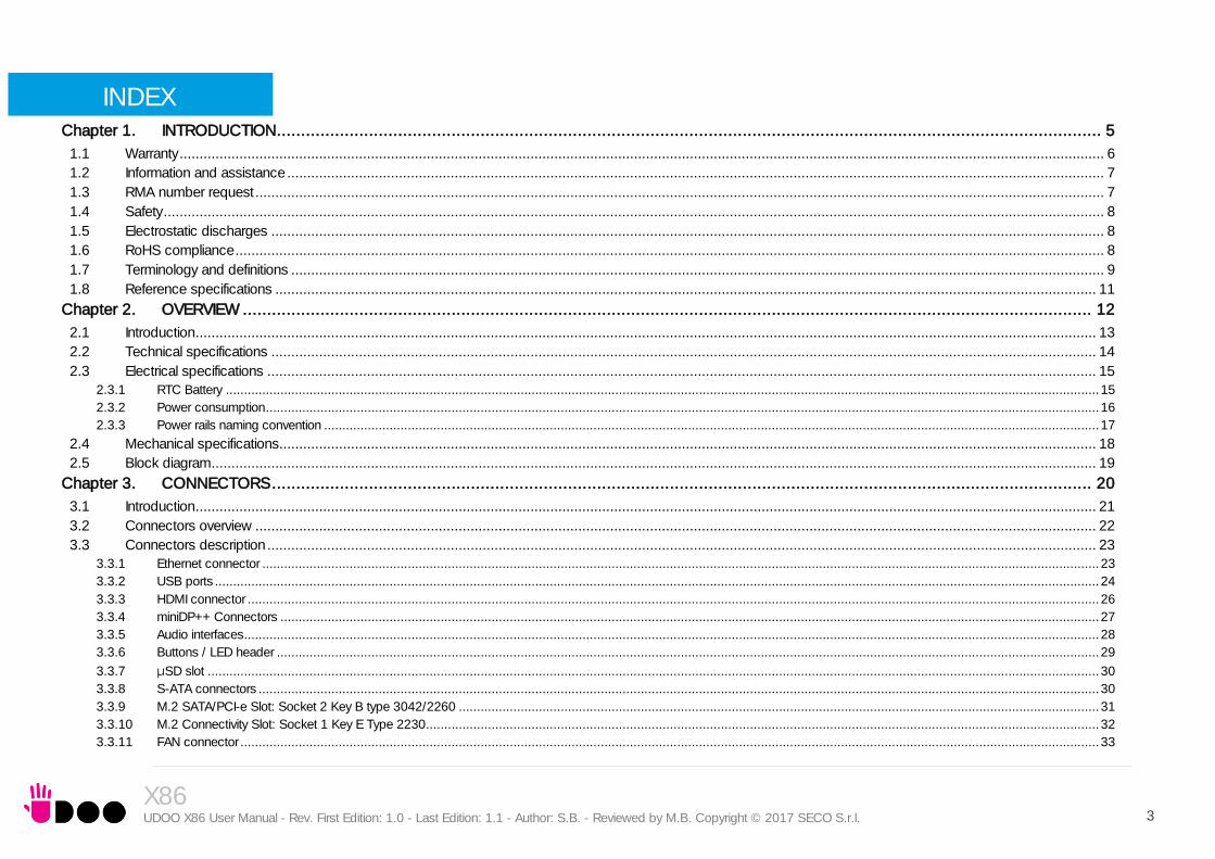
INDEX
INTRODUCTION .......................................................................................................................................................................... 5 Chapter 1.
1.1 Warranty ........................................................................................................................................................................................................................................ 6 1.2 Information and assistance ............................................................................................................................................................................................................. 7 1.3 RMA number request ..................................................................................................................................................................................................................... 7 1.4 Safety ............................................................................................................................................................................................................................................ 8 1.5 Electrostatic discharges ................................................................................................................................................................................................................. 8 1.6 RoHS compliance .......................................................................................................................................................................................................................... 8 1.7 Terminology and definitions ............................................................................................................................................................................................................ 9 1.8 Reference specifications .............................................................................................................................................................................................................. 11
OVERVIEW ............................................................................................................................................................................... 12 Chapter 2.
2.1 Introduction .................................................................................................................................................................................................................................. 13 2.2 Technical specifications ............................................................................................................................................................................................................... 14 2.3 Electrical specifications ................................................................................................................................................................................................................ 15
2.3.1 RTC Battery ................................................................................................................................................................................................................................................ 15 2.3.2 Power consumption ..................................................................................................................................................................................................................................... 16 2.3.3 Power rails naming convention ..................................................................................................................................................................................................................... 17
2.4 Mechanical specifications............................................................................................................................................................................................................. 18 2.5 Block diagram .............................................................................................................................................................................................................................. 19
CONNECTORS ......................................................................................................................................................................... 20 Chapter 3.
3.1 Introduction .................................................................................................................................................................................................................................. 21 3.2 Connectors overview ................................................................................................................................................................................................................... 22 3.3 Connectors description ................................................................................................................................................................................................................ 23
3.3.1 Ethernet connector ...................................................................................................................................................................................................................................... 23 3.3.2 USB ports ................................................................................................................................................................................................................................................... 24 3.3.3 HDMI connector .......................................................................................................................................................................................................................................... 26 3.3.4 miniDP++ Connectors ................................................................................................................................................................................................................................. 27 3.3.5 Audio interfaces ........................................................................................................................................................................................................................................... 28 3.3.6 Buttons / LED header .................................................................................................................................................................................................................................. 29 3.3.7 μSD slot ..................................................................................................................................................................................................................................................... 30 3.3.8 S-ATA connectors ....................................................................................................................................................................................................................................... 30 3.3.9 M.2 SATA/PCI-e Slot: Socket 2 Key B type 3042/2260 ................................................................................................................................................................................ 31 3.3.10 M.2 Connectivity Slot: Socket 1 Key E Type 2230 ......................................................................................................................................................................................... 32 3.3.11 FAN connector ............................................................................................................................................................................................................................................ 33

X86 UDOO X86 User Manual - Rev. First Edition: 1.0 - Last Edition: 1.1 - Author: S.B. - Reviewed by M.B. Copyright © 2017 SECO S.r.l. 4
3.3.12 UDOO Bricks connector .............................................................................................................................................................................................................................. 34 3.3.13 SPI Header .................................................................................................................................................................................................................................................. 34 3.3.14 ARDUINO interface + expansion connectors ................................................................................................................................................................................................. 34 3.3.15 IR Receiver .................................................................................................................................................................................................................................................. 37
UEFI BIOS SETUP ..................................................................................................................................................................... 38 Chapter 4.
4.1 InsydeH2O setup Utility ................................................................................................................................................................................................................ 39 4.2 Main setup menu ......................................................................................................................................................................................................................... 40
4.2.1 System Time / System Date ......................................................................................................................................................................................................................... 40 4.3 Advanced menu .......................................................................................................................................................................................................................... 41
4.3.1 Boot configuration submenu......................................................................................................................................................................................................................... 41 4.3.2 Security configuration (TXE) submenu ........................................................................................................................................................................................................... 41 4.3.3 Video configuration submenu ....................................................................................................................................................................................................................... 42 4.3.4 Chipset configuration submenu .................................................................................................................................................................................................................... 43 4.3.5 ACPI Table/features submenu ...................................................................................................................................................................................................................... 45 4.3.6 SATA configuration submenu ....................................................................................................................................................................................................................... 45 4.3.7 Console Redirection submenu ..................................................................................................................................................................................................................... 46 4.3.8 POST Hot Key submenu .............................................................................................................................................................................................................................. 48 4.3.9 Other configuration submenu ....................................................................................................................................................................................................................... 48
4.4 Security menu.............................................................................................................................................................................................................................. 49 4.5 Power menu ................................................................................................................................................................................................................................ 50
4.5.1 Advanced CPU control submenu ................................................................................................................................................................................................................. 52 4.5.2 EC Watchdog Configuration submenu .......................................................................................................................................................................................................... 53 4.5.3 Thermal Zone configuration submenu ........................................................................................................................................................................................................... 53
4.6 Boot menu .................................................................................................................................................................................................................................. 54 4.6.1 Legacy submenu ......................................................................................................................................................................................................................................... 56
4.7 Exit menu .................................................................................................................................................................................................................................... 57
APPENDICES............................................................................................................................................................................ 58 Chapter 5.
5.1 Accessories ................................................................................................................................................................................................................................. 59 5.1.1 M.2 Dual network modules .......................................................................................................................................................................................................................... 59

X86 UDOO X86 User Manual - Rev. First Edition: 1.0 - Last Edition: 1.1 - Author: S.B. - Reviewed by M.B. Copyright © 2017 SECO S.r.l. 5
Chapter 1.
Warranty Information and assistance RMA number request Safety Electrostatic discharges RoHS compliance Terminology and definitions Reference specifications

X86 UDOO X86 User Manual - Rev. First Edition: 1.0 - Last Edition: 1.1 - Author: S.B. - Reviewed by M.B. Copyright © 2017 SECO S.r.l. 6
1.1 Warranty
This product is subject to the Italian Law Decree 24/2002, acting European Directive 1999/44/CE on matters of sale and warranties to consumers.
The warranty on this product lasts for 2 years.
Under the warranty period, the Supplier guarantees the buyer assistance and service for repairing, replacing or credit of the item, at the Supplier’s own discretion.
Items cannot be returned unless previously authorized by the supplier.
The authorization is released after completing the specific form available on the web-site http://www.udoo.org/customer-care/ (Open a New Ticket Return Merchandise Application). The RMA authorization number must be put both on the packaging and on the documents shipped with the items, which must include all the accessories in their original packaging, with no signs of damage to, or tampering with, any returned item.
The error analysis form identifying the fault type must be completed by the customer and has must accompany the returned item.
Following a technical analysis, the supplier will verify if all the requirements, for which a warranty service applies, are met. If the warranty cannot be applied, the Supplier will calculate the minimum cost of this initial analysis on the item and the repair costs. Costs for replaced components will be calculated separately.
Warning! All changes or modifications to the equipment not explicitly approved by SECO S.r.l. could impair the equipment’s functionalities and could void the warranty

X86 UDOO X86 User Manual - Rev. First Edition: 1.0 - Last Edition: 1.1 - Author: S.B. - Reviewed by M.B. Copyright © 2017 SECO S.r.l. 7
1.2 Information and assistance
What do I have to do if I’m experiencing problems with my product?
The following services are available:
UDOO website: visit http://www.udoo.org to receive the latest information on the product. In most cases it is possible to find useful information to solve the problem.
UDOO Forum: join to the community of UDOO users. In the forum, available at http://www.udoo.org/forum/, it is possible to search the multiple topics of the community, and look for other users that had the same kind of problem - and how they solved it. It is also possible to post new topics to ask for specific help.
Repair centre: it is possible to send the faulty product to the SECO Repair Centre. In this case, follow this procedure:
o Returned items must be accompanied by a RMA Number. Items sent without the RMA number will be not accepted.
o Returned items must be shipped in an appropriate package. SECO is not responsible for damages caused by accidental drop, improper usage, or customer neglect.
Note: Please have the following information before asking for technical assistance:
Name and serial number of the product;
Description of Customer’s peripheral connections;
Description of Customer’s software (operating system, version, application software, etc.);
A complete description of the problem;
The exact words of every kind of error message encountered.
1.3 RMA number request
To request a RMA number, please visit UDOO web-site. On the bottom of the page, please select “Customer Care”, click on the “Open a New ticket” button and.
A RMA Number will be sent within 1 working day (only for on-line RMA requests).

X86 UDOO X86 User Manual - Rev. First Edition: 1.0 - Last Edition: 1.1 - Author: S.B. - Reviewed by M.B. Copyright © 2017 SECO S.r.l. 8
Always switch the power off, and unplug the power supply unit, before handling the board and/or connecting cables or other boards.
Avoid using metallic components - like paper clips, screws and similar - near the board when connected to a power supply, to avoid short circuits due to unwanted contacts with other board components.
If the board has become wet, never connect it to any external power supply unit or battery.
Check carefully that all cables are correctly connected and that they are not damaged.
Whenever handling a UDOO X86 board, ground yourself through an anti-static wrist strap. Placement of the board on an anti-static surface is also highly recommended.
1.4 Safety
The UDOO X86 board uses only extremely-low voltages.
While handling the board, please use extreme caution to avoid any kind of risk or damages to electronic components.
1.5 Electrostatic discharges
The UDOO X86 board, like any other electronic product, is an electrostatic sensitive device: high voltages caused by static electricity could damage some or all the devices and/or components on-board.
1.6 RoHS compliance
The UDOO X86 board is designed using RoHS compliant components and is manufactured on a lead-free production line. It is therefore fully RoHS compliant.

X86 UDOO X86 User Manual - Rev. First Edition: 1.0 - Last Edition: 1.1 - Author: S.B. - Reviewed by M.B. Copyright © 2017 SECO S.r.l. 9
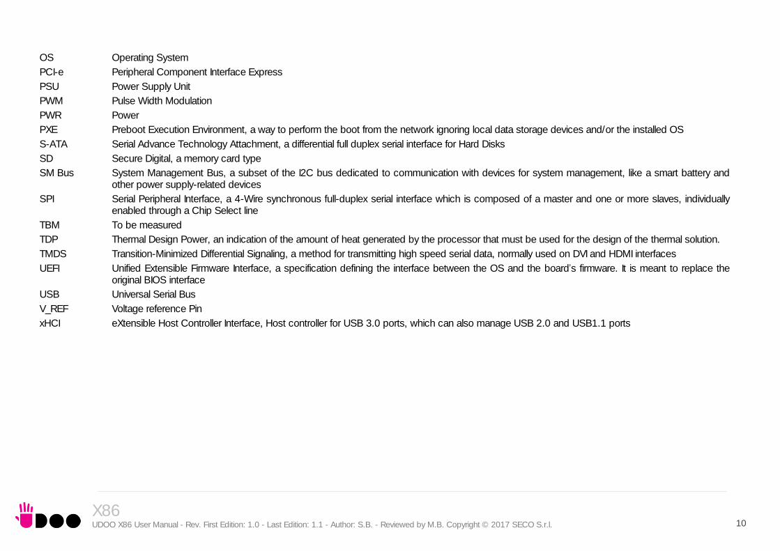
1.7 Terminology and definitions
ACPI Advanced Configuration and Power Interface, an open industrial standard for the board’s devices configuration and power management
AHCI Advanced Host Controller Interface, a standard which defines the operation modes of SATA interface
API Application Program Interface, a set of commands and functions that can be used by programmers for writing software for specific Operating Systems
BIOS Basic Input / Output System, the Firmware Interface that initializes the board before the OS starts loading
CEC Consumer Electronics Control, an HDMI feature which allows controlling more devices connected together by using only one remote control
DDC Display Data Channel, a kind of I2C interface for digital communication between displays and graphics processing units (GPU)
DDR Double Data Rate, a typology of memory devices which transfer data both on the rising and on the falling edge of the clock
DDR3L DDR, 3rd generation, Low voltage
DP++ Multimode Display Port, a video interface which can support both Display Port displays (directly) and HDMI/DVI displays (by using and external adapter)
GBE Gigabit Ethernet
Gbps Gigabits per second
GND Ground
GPI/O General purpose Input/Output
HD Audio High Definition Audio, most recent standard for hardware codecs developed by Intel® in 2004 for higher audio quality
HDMI High Definition Multimedia Interface, a digital audio and video interface
I2C Bus Inter-Integrated Circuit Bus, a simple serial bus consisting only of data and clock line, with multi-master capability
IoT Internet of Things
M.2 recent specifications for internal expansion modules, which defines many pinouts and sizes for different purposes. Can include SATA, PCI Express, USB, UART, DP interfaces
Mbps Megabits per second
MMC/eMMC MultiMedia Card / embedded MMC, a type of memory card, having the same interface as the SD card. The eMMC is the embedded version of the MMC. They are devices that incorporate the flash memories on a single BGA chip.
N.A. Not Applicable
N.C. Not Connected
OpenCL Open Computing Language, a software library based on C99 programming language, conceived explicitly to realise parallel computing using Graphics Processing Units (GPU)
OpenGL Open Graphics Library, an Open Source API dedicated to 2D and 3D graphics
X86 UDOO X86 User Manual - Rev. First Edition: 1.0 - Last Edition: 1.1 - Author: S.B. - Reviewed by M.B. Copyright © 2017 SECO S.r.l. 10
OS Operating System
PCI-e Peripheral Component Interface Express
PSU Power Supply Unit
PWM Pulse Width Modulation
PWR Power
PXE Preboot Execution Environment, a way to perform the boot from the network ignoring local data storage devices and/or the installed OS
S-ATA Serial Advance Technology Attachment, a differential full duplex serial interface for Hard Disks
SD Secure Digital, a memory card type
SM Bus System Management Bus, a subset of the I2C bus dedicated to communication with devices for system management, like a smart battery and other power supply-related devices
SPI Serial Peripheral Interface, a 4-Wire synchronous full-duplex serial interface which is composed of a master and one or more slaves, individually enabled through a Chip Select line
TBM To be measured
TDP Thermal Design Power, an indication of the amount of heat generated by the processor that must be used for the design of the thermal solution.
TMDS Transition-Minimized Differential Signaling, a method for transmitting high speed serial data, normally used on DVI and HDMI interfaces
UEFI Unified Extensible Firmware Interface, a specification defining the interface between the OS and the board’s firmware. It is meant to replace the original BIOS interface
USB Universal Serial Bus
V_REF Voltage reference Pin
xHCI eXtensible Host Controller Interface, Host controller for USB 3.0 ports, which can also manage USB 2.0 and USB1.1 ports
X86 UDOO X86 User Manual - Rev. First Edition: 1.0 - Last Edition: 1.1 - Author: S.B. - Reviewed by M.B. Copyright © 2017 SECO S.r.l. 11
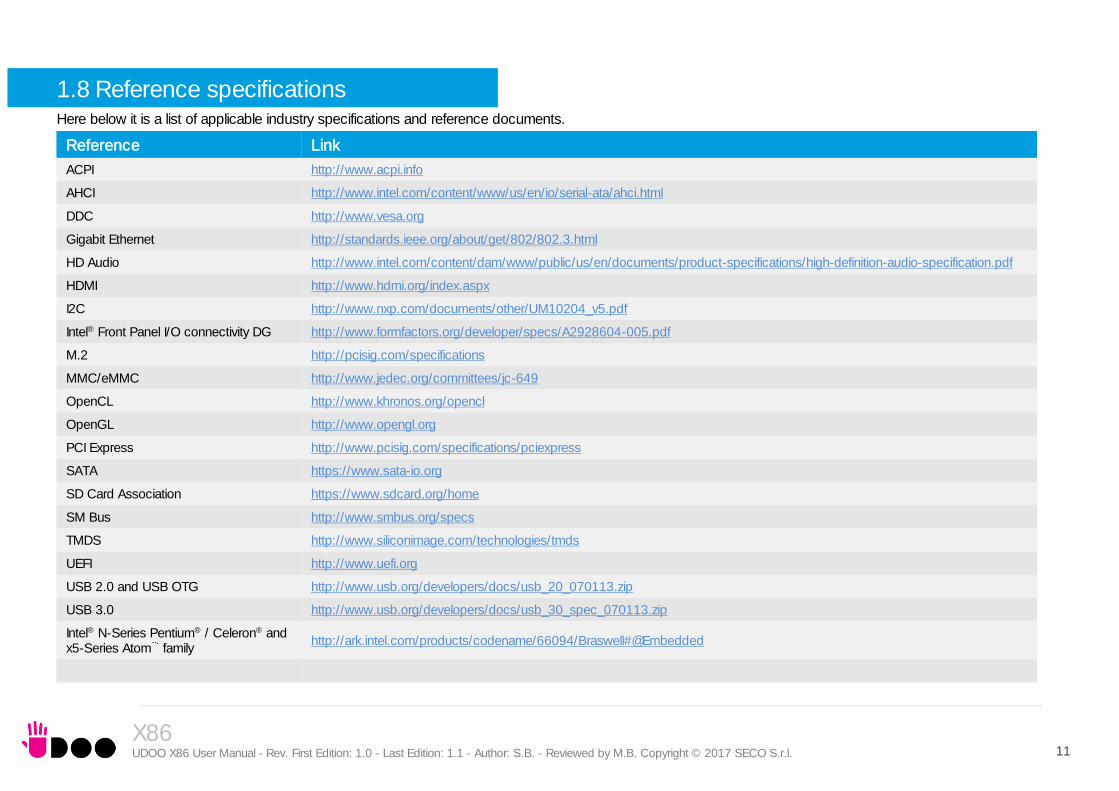
1.8 Reference specifications Here below it is a list of applicable industry specifications and reference documents.
Reference Link
ACPI http://www.acpi.info
AHCI http://www.intel.com/content/www/us/en/io/serial-ata/ahci.html
DDC http://www.vesa.org
Gigabit Ethernet http://standards.ieee.org/about/get/802/802.3.html
HD Audio http://www.intel.com/content/dam/www/public/us/en/documents/product-specifications/high-definition-audio-specification.pdf
HDMI http://www.hdmi.org/index.aspx
I2C http://www.nxp.com/documents/other/UM10204_v5.pdf
Intel® Front Panel I/O connectivity DG http://www.formfactors.org/developer/specs/A2928604-005.pdf
M.2 http://pcisig.com/specifications
MMC/eMMC http://www.jedec.org/committees/jc-649
OpenCL http://www.khronos.org/opencl
OpenGL http://www.opengl.org
PCI Express http://www.pcisig.com/specifications/pciexpress
SATA https://www.sata-io.org
SD Card Association https://www.sdcard.org/home
SM Bus http://www.smbus.org/specs
TMDS http://www.siliconimage.com/technologies/tmds
UEFI http://www.uefi.org
USB 2.0 and USB OTG http://www.usb.org/developers/docs/usb_20_070113.zip
USB 3.0 http://www.usb.org/developers/docs/usb_30_spec_070113.zip
Intel® N-Series Pentium® / Celeron® and x5-Series Atom family
http://ark.intel.com/products/codename/66094/Braswell#@Embedded

X86 UDOO X86 User Manual - Rev. First Edition: 1.0 - Last Edition: 1.1 - Author: S.B. - Reviewed by M.B. Copyright © 2017 SECO S.r.l. 12
Chapter 2.
Introduction Technical specifications Electrical specifications Mechanical specifications Block diagram

X86 UDOO X86 User Manual - Rev. First Edition: 1.0 - Last Edition: 1.1 - Author: S.B. - Reviewed by M.B. Copyright © 2017 SECO S.r.l. 13
2.1 Introduction
UDOO-X86 is a board designed specifically for maker’s / DIY market, embedding both a System-on-Chips (SoC) of the Intel® family of embedded SoCs formerly coded as Braswell, and an Arduino 101-compatible platform.
This board represents a junction point between the PC world, represented by the Braswell SoCs, and the Arduino 101 World, implemented on-board using an Intel® Curie microcontroller (the same used, indeed, in Arduino 101 boards).
All the SoCs mounted on UDOO X86 are Quad-Core, ranging from 2.00GHz up to 2.56 GHz, with 64-bit instruction set and very low TDP. This single chip solution includes the memory controller, which gives support for up to 8GB of DDR3L memory directly soldered on-board.
All SoCs embed an Intel® HD Graphics controller, with up to 16 Execution units, which offers high graphical performances, with support for Microsoft® DirectX11.1, OpenGL 4.2, OpenCL 1.2, OpenGL ES 3.0 and HW acceleration for video decoding of HEVC, H.264, MPEG2, MVC, VC-1, WMV9, JPEG/MJPEG and VP8 video standards (for H.264, MVC and JPEG/MJPEG also HW encoding is offered). This embedded GPU is able to drive three independent displays, by using the HDMI and the two miniDP++. Any combinations of these video interfaces are supported.
Other features offered by the N-Series Intel® Pentium® / Celeron® and x5-Series Atom family of SoCs, and included in UDOO X86 board, are two SATA Channels (one used for the common SATA / SSD drives, the other used to implement a M.2 Socket 2 Key B SSD slot), microSD interface, four USB ports (three USB 3.0 on standard Type-A sockets, one USB 2.0 on M.2 Socket 1 Key E Connectivity slot and another USB 2.0 port used for the communications with the Intel® Curie microcontroller), HD Audio and four PCI Express lanes (a PCI express lane is used for the implementation of the Gigabit Ethernet interface, two lanes are carried out on M.2 Socket 2 Key B SSD slot, the remaining is available on M.2 Socket 1 Key E Connectivity Slot)
Through the Intel® Braswell SoC’s USB interface #3 pass all the communications with the Intel® Curie microcontroller, which implements the Arduino 101 interface: this situation reproduces exactly the situation of an external Arduino board connected to an X86 PC, with the advantages given by an integrated board solution.
The Intel® Curie microcontroller, however, not only implements the Arduino 101 interface, but also offers an embedded Bluetooth Low Energy interface (with on-board antenna) and 6-axis combo sensor with accelerometer and gyroscope.
All these features, combined together, make UDOO X86 the most powerful maker board ever.
Please refer to following chapter for a complete list of all the integrated peripherals and the characteristics.

2.2 Technical specifications
SoC
Intel® Pentium® N3710, Quad Core @1.6GHz (Turbo Boost 2.56GHz), 2MB Cache, 6W TDP Intel® Celeron® N3160, Quad Core @1.6GHz (Turbo Boost 2.24GHz), 2MB Cache, 6W TDP Intel® Atom x5-E8000, Quad Core @1.04GHz, 2MB Cache, 5W TDP
Memory
Up to 8GB Dual Channel DDR3L Memory soldered on-board*
Graphics
Integrated Intel® HD Graphics controller Three independent display support HW decoding of HEVC(H.265), H.264, MPEG2, MVC, VC-1, VP8, WMV9, JPEG/MJPEG formats HW encoding of H.264, MVC and JPEG/MPEG formats
Video Interfaces
HDMI connector 2 x miniDP++ connectors
Video Resolution
Up to 3840 x 2160 24bpp @ 30Hz, 2560 x 1600 24bpp @60Hz
Mass Storage
Optional 32GB eMMC drive onboard SATA 7p M connector M.2 Key B SSD slot (Type 2242 or 2260 modules accepted) microSD Card slot
Networking
Realtek RTL811G Gigabit Ethernet controller Gigabit Ethernet LAN interface M.2 Key E Slot for optional Wireless modules Embedded Bluetooth Low Energy module + antenna
* Please notice that total amount of 8GB would be usable only with 64-bit OS. Total amount of memory available with a 32-bit OS depends on the OS itself (less than 4GB, however).
USB
3 x USB 3.0 Host ports on Type-A sockets 1 x USB 2.0 Host port on M.2 Key E slot
PCI-Express
1 x PCI-e x2 port on M.2 Key B SSD Slot 1 x PCI-e x1 port on M.2 Key E slot
Audio
HD Audio Codec Realtek ALC283 Combo TRSS connector with Mic In and Line out support S/PDIF signal 2 x Speaker internal headers
Serial ports
2 x UART with Flow Control ports
Other Interfaces
Up to 20 extended GPIOs, multiplexed with other interfaces LPC, 2x I2C, T/S signals, GPIOs on expansion connector I2C UDOO bricks connector SPI Connector Switch/LED Front Panel Header CIR (Consumer InfraRed) Sensor Arduino 101 compatible shield Integrated 6-axis combo sensor with accelerometer and gyroscope
Power supply: +12VDC ± 5% RTC Coin cell Battery
Operating temperature: 0°C ÷ +60°C** (Commercial temperature)
Dimensions: 120 x 85 mm (4.72” x 3.35”).
Supported Operating Systems:
Microsoft® Windows 10, 8.1, 7 Any Linux distribution for X86 64-bit platform Android-x86
** Temperatures indicated are the maximum temperature that the
heatspreader / heatsink can reach in any of its parts. This means that it is customer’s responsibility to use any passive cooling solution along with an application-dependent cooling system, capable to ensure that the heatspreader / heatsink temperature remains in the range above indicated.
CAUTION: handling batteries incorrectly or replacing with not-approved devices may present a risk of fire or explosion.
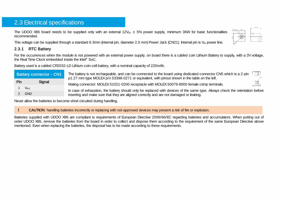
2.3 Electrical specifications
The UDOO X86 board needs to be supplied only with an external 12VDC ± 5% power supply, minimum 36W for basic functionalities recommended.
This voltage can be supplied through a standard 6.3mm (internal pin, diameter 2.0 mm) Power Jack (CN21). Internal pin is VIN power line.
2.3.1 RTC Battery
For the occurrences when the module is not powered with an external power supply, on board there is a cabled coin Lithium Battery to supply, with a 3V voltage, the Real Time Clock embedded inside the Intel® SoC.
Battery used is a cabled CR2032-LD Lithium coin-cell battery, with a nominal capacity of 220mAh.
The battery is not rechargeable, and can be connected to the board using dedicated connector CN5 which is a 2-pin p1.27 mm type MOLEX p/n 53398-0271 or equivalent, with pinout shown in the table on the left.
Mating connector: MOLEX 51021-0200 receptacle with MOLEX 50079-8000 female crimp terminals.
In case of exhaustion, the battery should only be replaced with devices of the same type. Always check the orientation before inserting and make sure that they are aligned correctly and are not damaged or leaking.
Never allow the batteries to become short-circuited during handling.
Batteries supplied with UDOO X86 are compliant to requirements of European Directive 2006/66/EC regarding batteries and accumulators. When putting out of order UDOO X86, remove the batteries from the board in order to collect and dispose them according to the requirement of the same European Directive above mentioned. Even when replacing the batteries, the disposal has to be made according to these requirements.
Battery connector - CN1
Pin Signal
1 VRTC
2 GND

X86 UDOO X86 User Manual - Rev. First Edition: 1.0 - Last Edition: 1.1 - Author: S.B. - Reviewed by M.B. Copyright © 2017 SECO S.r.l. 16
2.3.2 Power consumption
Using the following setup, and using all possible SoCs offered for UDOO X86 board, the current consumption (RMS) has been measured on the VIN Power line when the board is supplied through DC power jack CN23 using a +12VDC Notebook DC Adapter.
O.S. Windows 10 Professional 32GB eMMC onboard USB mouse and keyboard connected HDMI display connected, resolution 1920x1080. UEFI BIOS Release 1.01
Independently by the SoC mounted onboard, the following power consumptions are common to all boards:
Battery Backup power consumption: 5.7μA Soft-Off State power consumption: 53.7mA Suspend State power consumption: 59.8mA
Please consider that the power consumption depends strongly on the utilization scenario.
For this reasons, it is recommended to use PSU with a minimum power of 36W for basic functionalities
Status
SoC / Configuration
N3710 32GB eMMC
8GB RAM
N3160 32GB eMMC
4GB RAM
x5-E3800 32GB eMMC
2GB RAM
Inrush current at boot 920mA 748mA 542mA
Idle, power saving configuration 307mA 264mA 314mA
OS Boot, power saving configuration 454mA 342mA 316mA
Video reproduction@720p, power saving configuration 372mA 359mA 336mA
Video reproduction@1080p, power saving configuration 487mA 420mA 335mA
Internal Stress Test Tool, maximum performance 1008mA 1020mA 906mA

X86 UDOO X86 User Manual - Rev. First Edition: 1.0 - Last Edition: 1.1 - Author: S.B. - Reviewed by M.B. Copyright © 2017 SECO S.r.l. 17
2.3.3 Power rails naming convention
In all the tables contained in this manual, Power rails are named with the following meaning:
_S: Switched voltages, i.e. power rails that are active only when the board is in ACPI’s S0 (Working) state. Examples: +3.3V_S, +5V_S.
_A: Always-on voltages, i.e. power rails that are active both in ACPI’s S0 (Working), S3 (Standby) and S5 (Soft Off) state. Examples: +5V_A, +3.3V_A.
Other suffixes are used for application specific power rails, which are derived from same voltage value of voltage switched rails, if it is not differently stated (for example, +5VHDMI is derived from +5V_S, and so on).

X86 UDOO X86 User Manual - Rev. First Edition: 1.0 - Last Edition: 1.1 - Author: S.B. - Reviewed by M.B. Copyright © 2017 SECO S.r.l. 18
2.4 Mechanical specifications
The board dimensions are 120 x 85 mm (4.72” x 3.35”).
The printed circuit of the board is made of ten layers, some of them are ground planes, for disturbance rejection.
X86 UDOO X86 User Manual - Rev. First Edition: 1.0 - Last Edition: 1.1 - Author: S.B. - Reviewed by M.B. Copyright © 2017 SECO S.r.l. 19
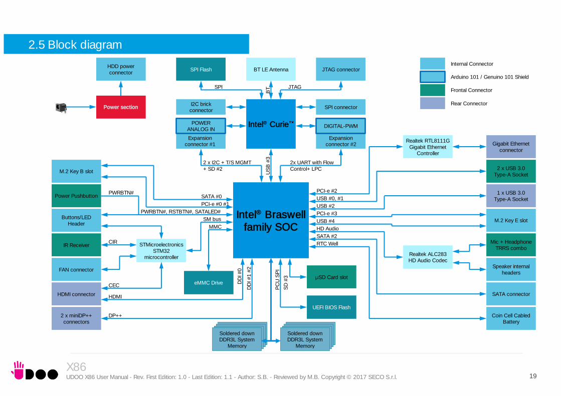
Intel® Braswell family SOC
Power section
Soldered down DDR3L System
Memory
Soldered down DDR3L System
Memory
Buttons/LED Header
JTAG connector
IR Receiver
FAN connector
HDMI connector
Realtek RTL8111G Gigabit Ethernet
Controller
Gigabit Ethernet connector
2 x USB 3.0 Type-A Socket
1 x USB 3.0 Type-A Socket
M.2 Key E slot
Speaker internal headers
SATA connector
Coin Cell Cabled Battery
Realtek ALC283 HD Audio Codec
STMicroelectronics STM32
microcontroller
PC
U S
PI
UEFI BIOS Flash
Intel® Curie
PCI-e #3
USB #4
SM bus
CIR
CEC
HDMI
DP++
USB #0, #1
USB #2
HD Audio
SATA #2
RTC Well
Power Pushbutton PCI-e #2
DD
I #1 #
2
DD
I #0
Expansion connector #1
2 x I2C + T/S MGMT + SD #2
2x UART with Flow Control+ LPC
US
B #
3
Mic + Headphone TRRS combo
2 x miniDP++ connectors
PWRBTN#, RSTBTN#, SATALED#
SATA #0
Internal Connector
Frontal Connector
Rear Connector
eMMC Drive
MMC
POWER ANALOG IN
SPI Flash
Arduino 101 / Genuino 101 Shield
BT LE Antenna
BT SPI JTAG
HDD power connector
μSD Card slot
SD
#3
PWRBTN#
PCI-e #0 #1
M.2 Key B slot
I2C brick connector
Expansion connector #2
DIGITAL-PWM
SPI connector
2.5 Block diagram
X86 UDOO X86 User Manual - Rev. First Edition: 1.0 - Last Edition: 1.1 - Author: S.B. - Reviewed by M.B. Copyright © 2017 SECO S.r.l. 20
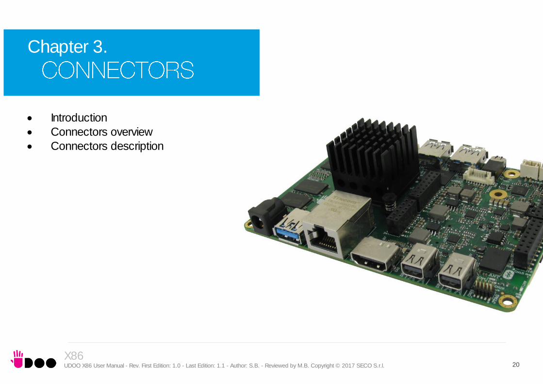
Chapter 3.
Introduction Connectors overview Connectors description
X86 UDOO X86 User Manual - Rev. First Edition: 1.0 - Last Edition: 1.1 - Author: S.B. - Reviewed by M.B. Copyright © 2017 SECO S.r.l. 21
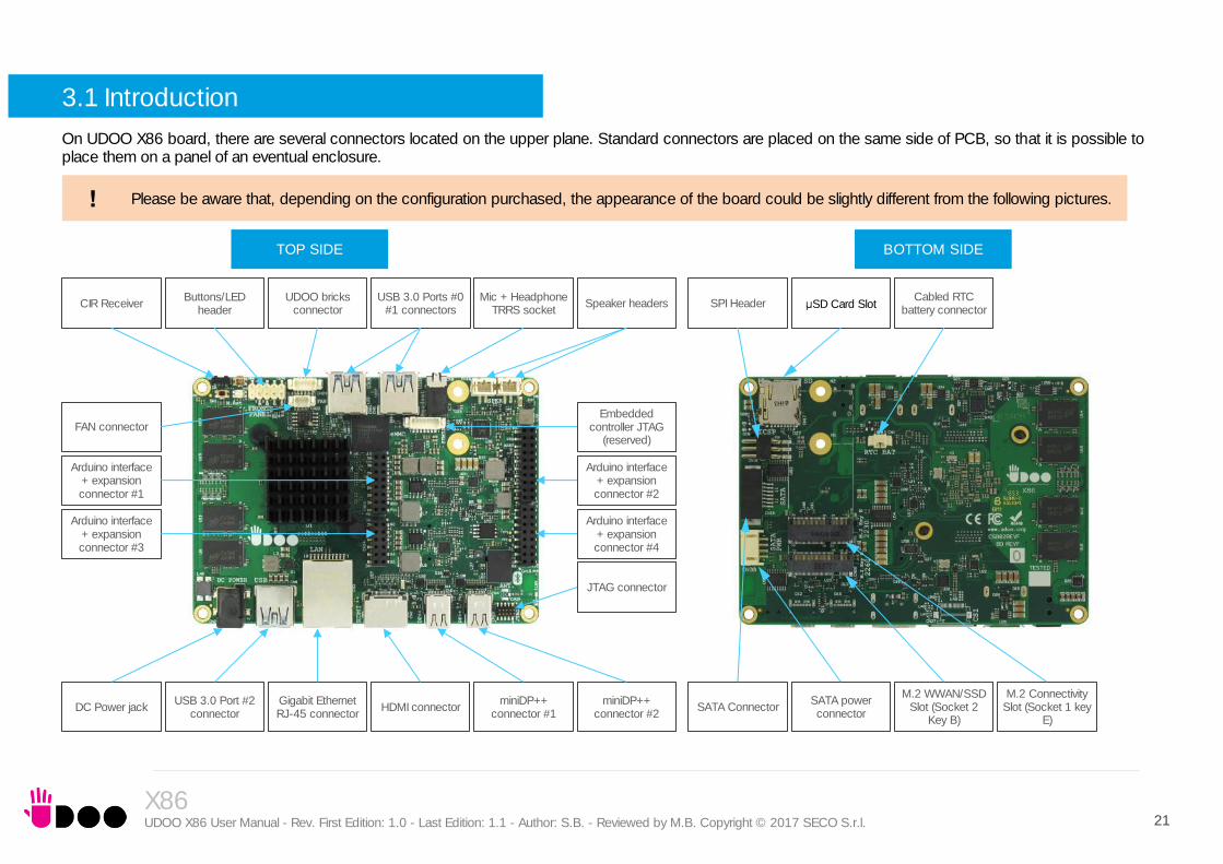
3.1 Introduction
On UDOO X86 board, there are several connectors located on the upper plane. Standard connectors are placed on the same side of PCB, so that it is possible to place them on a panel of an eventual enclosure.
TOP SIDE BOTTOM SIDE
Please be aware that, depending on the configuration purchased, the appearance of the board could be slightly different from the following pictures.
Buttons/LED header
Arduino interface + expansion connector #3
DC Power jack
Arduino interface + expansion connector #4
Arduino interface + expansion connector #2
CIR Receiver
USB 3.0 Port #2 connector
Gigabit Ethernet RJ-45 connector
HDMI connector miniDP++
connector #1 miniDP++
connector #2
Embedded controller JTAG
(reserved)
UDOO bricks connector
USB 3.0 Ports #0 #1 connectors
Mic + Headphone TRRS socket
Speaker headers
JTAG connector
Arduino interface + expansion connector #1
FAN connector
SPI Header µSD Card Slot Cabled RTC
battery connector
SATA Connector SATA power connector
M.2 WWAN/SSD Slot (Socket 2
Key B)
M.2 Connectivity Slot (Socket 1 key
E)

X86 UDOO X86 User Manual - Rev. First Edition: 1.0 - Last Edition: 1.1 - Author: S.B. - Reviewed by M.B. Copyright © 2017 SECO S.r.l. 22
3.2 Connectors overview
Name Description Name Description
CN1 Cabled RTC Battery CN15 Arduino interface + expansion connector #4
CN2 HDMI connector CN16 SPI Header
CN3 Gigabit Ethernet connector CN17 µSD Card Slot
CN4 miniDP++ connector #2 CN18 SATA Port #1 M 7p connector
CN5 miniDP++ connector #1 CN19 M.2 Connectivity Slot (Socket 1 Key E Type 2230)
CN6 USB 3.0 Port #0 CN20 M.2 SATA/PCI-e Slot (Socket 2 Key B type 2242 / 3042 or 2260)
CN7 USB 3.0 Port #1 CN21 DC IN Power Jack
CN8 USB 3.0 Port #2 CN22 FAN Header 3p
CN9 Mic + Headphone TRRS socket CN23 STM Controller JTAG Connector (reserved)
CN10 Right Speaker Connector CN24 UDOO Bricks connector
CN11 Left Speaker Connector CN25 Button/LED Internal Header
CN12 Arduino interface + expansion connector #1 CN28 JTAG connector
CN13 Arduino interface + expansion connector #2 CN30 SATA Power Connector
CN14 Arduino interface + expansion connector #3 U48 IR Receiver
X86 UDOO X86 User Manual - Rev. First Edition: 1.0 - Last Edition: 1.1 - Author: S.B. - Reviewed by M.B. Copyright © 2017 SECO S.r.l. 23
3.3 Connectors description
3.3.1 Ethernet connector
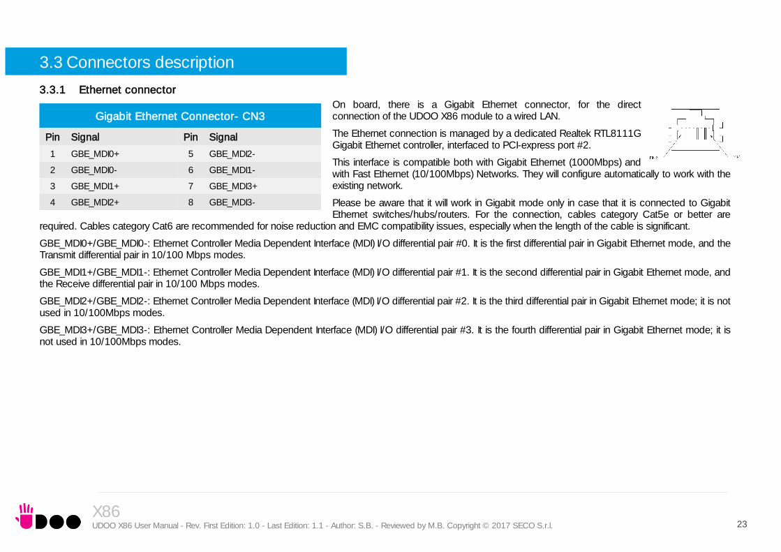
On board, there is a Gigabit Ethernet connector, for the direct connection of the UDOO X86 module to a wired LAN.
The Ethernet connection is managed by a dedicated Realtek RTL8111G Gigabit Ethernet controller, interfaced to PCI-express port #2.
This interface is compatible both with Gigabit Ethernet (1000Mbps) and with Fast Ethernet (10/100Mbps) Networks. They will configure automatically to work with the existing network.
Please be aware that it will work in Gigabit mode only in case that it is connected to Gigabit Ethernet switches/hubs/routers. For the connection, cables category Cat5e or better are
required. Cables category Cat6 are recommended for noise reduction and EMC compatibility issues, especially when the length of the cable is significant.
GBE_MDI0+/GBE_MDI0-: Ethernet Controller Media Dependent Interface (MDI) I/O differential pair #0. It is the first differential pair in Gigabit Ethernet mode, and the Transmit differential pair in 10/100 Mbps modes.
GBE_MDI1+/GBE_MDI1-: Ethernet Controller Media Dependent Interface (MDI) I/O differential pair #1. It is the second differential pair in Gigabit Ethernet mode, and the Receive differential pair in 10/100 Mbps modes.
GBE_MDI2+/GBE_MDI2-: Ethernet Controller Media Dependent Interface (MDI) I/O differential pair #2. It is the third differential pair in Gigabit Ethernet mode; it is not used in 10/100Mbps modes.
GBE_MDI3+/GBE_MDI3-: Ethernet Controller Media Dependent Interface (MDI) I/O differential pair #3. It is the fourth differential pair in Gigabit Ethernet mode; it is not used in 10/100Mbps modes.
Gigabit Ethernet Connector- CN3
Pin Signal Pin Signal
1 GBE_MDI0+ 5 GBE_MDI2-
2 GBE_MDI0- 6 GBE_MDI1-
3 GBE_MDI1+ 7 GBE_MDI3+
4 GBE_MDI2+ 8 GBE_MDI3-

X86 UDOO X86 User Manual - Rev. First Edition: 1.0 - Last Edition: 1.1 - Author: S.B. - Reviewed by M.B. Copyright © 2017 SECO S.r.l. 24
3.3.2 USB ports
The Intel® Braswell family of SoCs used on UDOO X86 board can manage up to four USB SuperSpeed (i.e., USB 3.0 compliant) ports and five High Speed (i.e. USB 2.0 compliant) ports. There is only one dedicated High Speed port, the other four ports are shared with the SuperSpeed ports, i.e. they can be used either by USB 2.0 or USB 3.0.
The USB 3.0 ports #0 and #1 are available on two single USB connectors, CN6 and CN7, placed on the same side of the PCB (“Frontal”), while USB 3.0 port #2 is available on USB connector CN8 placed on the opposite side (“Rear”). “Rear” and “Frontal” terms are used considering a possible application of this board with an enclosure). The connectors used are standard USB 3.0 type-A receptacles.
Since these connectors are standard type-A receptacle, they can be connected to all types of USB 1.1 / USB 2.0 / USB 3.0 devices using standard-A USB 3.0 or USB 2.0 plugs.
For USB 3.0 connections it is mandatory the use of SuperSpeed certified cables, whose SuperSpeed differential pairs are individually shielded inside the global cable’s external shielding.
Signal description:
USB_P0+/USB_P0-: USB 2.0 Port #0 differential pair.
USB_SSRX0+/USB_SSRX0-: USB Super Speed Port #0 receive differential pair.
USB_SSTX0+/USB_SSTX0-: USB Super Speed Port #0 transmit differential pair.
USB_P1+/USB_P1-: USB 2.0 Port #1 differential pair.
USB_SSRX1+/USB_SSRX1-: USB Super Speed Port #1 receive differential pair.
USB_SSTX1+/USB_SSTX1-: USB Super Speed Port #1 transmit differential pair.
USB 3.0 port#0 type A receptacle - CN6
Pin Signal Pin Signal
1 +5VUSB0 5 USB_SSRX0-
2 USB_P0- 6 USB_SSRX0+
3 USB_P0+ 7 GND
4 GND 8 USB_SSTX0-
9 USB_SSTX0+
USB 3.0 port#1 type A receptacle - CN7
Pin Signal Pin Signal
1 +5VUSB1 5 USB_SSRX1-
2 USB_P1- 6 USB_SSRX1+
3 USB_P1+ 7 GND
4 GND 8 USB_SSTX1-
9 USB_SSTX1+
USB 3.0 port #2 type-A receptacle - CN8
Pin Signal Pin Signal
1 +5VUSB2 5 USB_SSRX2-
2 USB_P2- 6 USB_SSRX2+
3 USB_P2+ 7 GND
4 GND 8 USB_SSTX2-
9 USB_SSTX2+

X86 UDOO X86 User Manual - Rev. First Edition: 1.0 - Last Edition: 1.1 - Author: S.B. - Reviewed by M.B. Copyright © 2017 SECO S.r.l. 25
USB_P2+/USB_P2-: USB 2.0 Port #2 differential pair.
USB_P3+/USB_P4-: USB 2.0 Port #3 differential pair.
Common mode chokes are placed on all USB differential pairs for EMI compliance.
For ESD protection, on all data and voltage lines are placed clamping diodes for voltage transient suppression.
Please be aware that Windows® 7 OS doesn’t have native support for the xHCI controller. It will be supported only after installing chipset’s driver. This could lead to problems during OS installation, since during this phase USB keyboard and mouse will not work, if connected to any of the USB ports available on UDOO X86 board.
It is possible to force the UEFI BIOS support for Mouse and Keyboard on USB ports by entering “InsydeH2O Setup utility” (“Advanced” menu “Other Configuration” submenu “Win7 Keyboard/Mouse Support”, see paragraph 4.3.9) before performing Windows® 7 and chipset’s driver installation
X86 UDOO X86 User Manual - Rev. First Edition: 1.0 - Last Edition: 1.1 - Author: S.B. - Reviewed by M.B. Copyright © 2017 SECO S.r.l. 26
3.3.3 HDMI connector
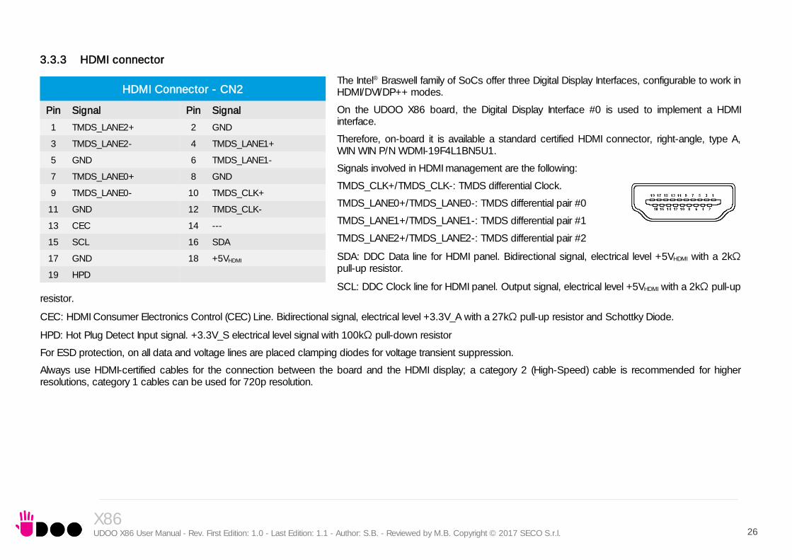
The Intel® Braswell family of SoCs offer three Digital Display Interfaces, configurable to work in HDMI/DVI/DP++ modes.
On the UDOO X86 board, the Digital Display Interface #0 is used to implement a HDMI interface.
Therefore, on-board it is available a standard certified HDMI connector, right-angle, type A, WIN WIN P/N WDMI-19F4L1BN5U1.
Signals involved in HDMI management are the following:
TMDS_CLK+/TMDS_CLK-: TMDS differential Clock.
TMDS_LANE0+/TMDS_LANE0-: TMDS differential pair #0
TMDS_LANE1+/TMDS_LANE1-: TMDS differential pair #1
TMDS_LANE2+/TMDS_LANE2-: TMDS differential pair #2
SDA: DDC Data line for HDMI panel. Bidirectional signal, electrical level +5VHDMI with a 2kΩ pull-up resistor.
SCL: DDC Clock line for HDMI panel. Output signal, electrical level +5VHDMI with a 2kΩ pull-up resistor.
CEC: HDMI Consumer Electronics Control (CEC) Line. Bidirectional signal, electrical level +3.3V_A with a 27kΩ pull-up resistor and Schottky Diode.
HPD: Hot Plug Detect Input signal. +3.3V_S electrical level signal with 100kΩ pull-down resistor
For ESD protection, on all data and voltage lines are placed clamping diodes for voltage transient suppression.
Always use HDMI-certified cables for the connection between the board and the HDMI display; a category 2 (High-Speed) cable is recommended for higher resolutions, category 1 cables can be used for 720p resolution.
HDMI Connector - CN2
Pin Signal Pin Signal
1 TMDS_LANE2+ 2 GND
3 TMDS_LANE2- 4 TMDS_LANE1+
5 GND 6 TMDS_LANE1-
7 TMDS_LANE0+ 8 GND
9 TMDS_LANE0- 10 TMDS_CLK+
11 GND 12 TMDS_CLK-
13 CEC 14 ---
15 SCL 16 SDA
17 GND 18 +5VHDMI
19 HPD

X86 UDOO X86 User Manual - Rev. First Edition: 1.0 - Last Edition: 1.1 - Author: S.B. - Reviewed by M.B. Copyright © 2017 SECO S.r.l. 27
3.3.4 miniDP++ Connectors
On the UDOO X86 board, the Digital Display Interfaces #1 and #2 are used to implement a multimode Display Port (DP++)interface, i.e. it can be used to support DP displays directly and, through an external adapter, also HDMI or DVI displays.
Such an interface is available on as many miniDP connectors, type Pulse Electronics p/n E9320-001-01 or equivalent, with the pinout shown in the table on the left.
The configuration of this interface in DP or HDMI/DVI mode is automatic, and it is driven by the CAD signals available on pin 4.
When a DP cable is connected, then the CAD signal is not connected; this interface will recognize it, and on pins 16/18 there will be the Display Port Auxiliary channel signals. Instead, when a DP-to-HDMI adapter is mounted, it will drive opportunely the CAD signal, which will make available HDMI_CTRL_CLK and HDMI_CTRL_DAT signals on the same pins.
Further signals involved in DP management are the following:
DPx_LANE0+/DPx_LANE0-: Display Port differential pair #0.
DPx_LANE1+/DPx_LANE1-: Display Port differential pair #1.
DPx_LANE2+/DPx_LANE2-: Display Port differential pair #2.
DPx_LANE3+/DPx_LANE3-: Display Port differential pair #3.
DPx_HPD: Hot Plug Detect Input signal.
HDMIx_CEC: HDMI Consumer Electronics Control (CEC) Line. This signal is used only for HDMI compatibility when a HDMI adapter is connected to the DP connector.
miniDP++ Connector # 1- CN5
Pin Signal Pin Signal
1 GND 2 DP1_HPD
3 DP1_LANE0+ 4 CAD
5 DP1_LANE0- 6 HDMI1_CEC
7 GND 8 GND
9 DP1_LANE1+ 10 DP1_LANE3+
11 DP1_LANE1- 12 DP1_LANE3-
13 GND 14 GND
15 DP1_LANE2+ 16 HDMI1_CTRL_CLK / DP1_AUX+
17 DP1_LANE2- 18 HDMI1_CTRL_DAT / DP1_AUX-
19 GND 20 +3.3V_S
miniDP++ Connector #2- CN4
Pin Signal Pin Signal
1 GND 2 DP_HPD
3 DP2_LANE0+ 4 CAD
5 DP2_LANE0- 6 HDMI2_CEC
7 GND 8 GND
9 DP2_LANE1+ 10 DP2_LANE3+
11 DP2_LANE1- 12 DP2_LANE3-
13 GND 14 GND
15 DP2_LANE2+ 16 HDMI2_CTRL_CLK / DP2_AUX+
17 DP2_LANE2- 18 HDMI2_CTRL_DAT / DP2_AUX-
19 GND 20 +3.3V_S

X86 UDOO X86 User Manual - Rev. First Edition: 1.0 - Last Edition: 1.1 - Author: S.B. - Reviewed by M.B. Copyright © 2017 SECO S.r.l. 28
3.3.5 Audio interfaces
In the UDOO X86 board, audio functionalities are provided by a Realtek ALC283 High Definition Audio Codec.
In order to reduce the space dedicated to connectors, there is a TRRS Combo Audio Socket, i.e. a single socket which offer both stereo Line Out and Mic In functionalities.
Such TRRS Combo Audio socket can be used with any 4-poles 3.5mm diameter audio jack, with pinout compatible with the most recent Headsets, shown in the table on the left.
Additionally, it is also possible to connect external stereo speakers by using the dedicated connectors CN10 and CN11, which are two connectors type HR p/n A2001WV-S-02PD01 or equivalent.
Mating connector: HR p/n A2001H-02P with A2001 series female crimp terminals.
TRRS Audio socket- CN9
Pin Signal
TIP Headphone Out Left Channel
RING1 Headphone Out Right Channel
RING2 GND
SLEEVE MIC_IN
Right Speaker Connector- CN10
Pin Signal
1 Speaker Right Channel +
2 Speaker Right Channel -
Left Speaker Connector- CN11
1 Speaker Left Channel -
2 Speaker Left Channel +
X86 UDOO X86 User Manual - Rev. First Edition: 1.0 - Last Edition: 1.1 - Author: S.B. - Reviewed by M.B. Copyright © 2017 SECO S.r.l. 29
3.3.6 Buttons / LED header
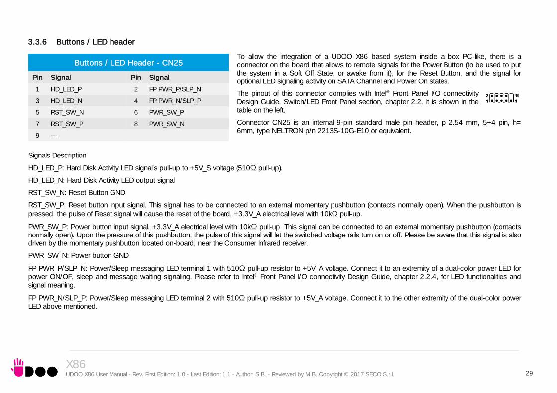
To allow the integration of a UDOO X86 based system inside a box PC-like, there is a connector on the board that allows to remote signals for the Power Button (to be used to put the system in a Soft Off State, or awake from it), for the Reset Button, and the signal for optional LED signaling activity on SATA Channel and Power On states.
The pinout of this connector complies with Intel® Front Panel I/O connectivity Design Guide, Switch/LED Front Panel section, chapter 2.2. It is shown in the table on the left.
Connector CN25 is an internal 9-pin standard male pin header, p 2.54 mm, 5+4 pin, h= 6mm, type NELTRON p/n 2213S-10G-E10 or equivalent.
Signals Description
HD_LED_P: Hard Disk Activity LED signal’s pull-up to +5V_S voltage (510Ω pull-up).
HD_LED_N: Hard Disk Activity LED output signal
RST_SW_N: Reset Button GND
RST_SW_P: Reset button input signal. This signal has to be connected to an external momentary pushbutton (contacts normally open). When the pushbutton is pressed, the pulse of Reset signal will cause the reset of the board. +3.3V_A electrical level with 10kΩ pull-up.
PWR_SW_P: Power button input signal, +3.3V_A electrical level with 10kΩ pull-up. This signal can be connected to an external momentary pushbutton (contacts normally open). Upon the pressure of this pushbutton, the pulse of this signal will let the switched voltage rails turn on or off. Please be aware that this signal is also driven by the momentary pushbutton located on-board, near the Consumer Infrared receiver.
PWR_SW_N: Power button GND
FP PWR_P/SLP_N: Power/Sleep messaging LED terminal 1 with 510Ω pull-up resistor to +5V_A voltage. Connect it to an extremity of a dual-color power LED for power ON/OF, sleep and message waiting signaling. Please refer to Intel® Front Panel I/O connectivity Design Guide, chapter 2.2.4, for LED functionalities and signal meaning.
FP PWR_N/SLP_P: Power/Sleep messaging LED terminal 2 with 510Ω pull-up resistor to +5V_A voltage. Connect it to the other extremity of the dual-color power LED above mentioned.
Buttons / LED Header - CN25
Pin Signal Pin Signal
1 HD_LED_P 2 FP PWR_P/SLP_N
3 HD_LED_N 4 FP PWR_N/SLP_P
5 RST_SW_N 6 PWR_SW_P
7 RST_SW_P 8 PWR_SW_N
9 ---

X86 UDOO X86 User Manual - Rev. First Edition: 1.0 - Last Edition: 1.1 - Author: S.B. - Reviewed by M.B. Copyright © 2017 SECO S.r.l. 30
3.3.7 μSD slot
The SoCs used on UDOO X86 module offer a SD 3.0 compliant interface, that can be used to implement another mass storages media other than the optional internal eMMC and the two SATA interfaces.
This SD interface is carried to a standard μSD card slot (CN17), soldered on top side of the module, push-push type.
3.3.8 S-ATA connectors
The N-series Intel® Pentium® / Celeron® and x5-Series Atom SoCs embed a SATA Controller, which offers two SATA III, 6.0 Gbps interfaces.
Of these interfaces, one SATA channel is carried out to a standard male S-ATA connector, CN18 (the other SATA channel is available on the M.2 Key B socket, CN20, please check par. 3.3.9).
Here following the signals related to SATA interface:
SATA1_TX+/SATA1_TX-: Serial ATA Channel #1 Transmit differential pair
SATA1_RX+/SATA1_RX-: Serial ATA Channel #1 Receive differential pair
10nF AC series decoupling capacitors are placed on each line of SATA differential pairs.
A dedicated power connector, CN21, can be used to give supply to external Hard Drives (or Solid State Drives) connected to the SATA male connector.
The dedicated power connector is a 4-pin male connector, type JST p/n S4B-PH-SM4-TB or equivalent, with pinout shown in the table on the left.
Mating connector: JST PHR-4 crimp housing with JST SPH-002T-P0.5L crimp terminals.
S-ATA Connector - CN18
Pin Signal
1 GND
2 SATA1_Tx+
3 SATA1_Tx-
4 GND
5 SATA1_Rx-
6 SATA1_Rx+
7 GND
S-ATA Power Connector - CN30
Pin Signal
1 ---
2 GND
3 GND
4 +5V_S

X86 UDOO X86 User Manual - Rev. First Edition: 1.0 - Last Edition: 1.1 - Author: S.B. - Reviewed by M.B. Copyright © 2017 SECO S.r.l. 31
3.3.9 M.2 SATA/PCI-e Slot: Socket 2 Key B type 2242/3042/2260
The mass storage capabilities of the UDOO X86 are completed by an M.2 SSD Slot, which allow plugging M.2 Socket 2 Key B Solid State Drives with SATA interface or PCI-e x2 interface (PCI-e x1 is also supported).
The connector used for the M.2 SATA/PCI-e slot is CN20, which is a standard 75 pin M.2 Key B connector, type LOTES p/n APCI0087-P001A, H=8.5mm, with the pinout shown in the table on the left.
On the UDOO X86 board there is also a Threaded Spacer which allows the placement of M.2 Socket 2 Key B SATA/PCI-e modules in 2260 size.
It is possible to place also modules in 2242 or 3042 size, by using a M/F Spacer which allows fixing the M.2 module on the spacer already available on the PCB, deemed for the fixing of the M.2 connectivity slot (see next paragraph)
Here following the signals related to the SATA interface:
SATA0_Tx+/SATA0_Tx-: Serial ATA Channel #0 Transmit differential pair
SATA0_Rx+/SATA0_Rx-: Serial ATA Channel #0 Receive differential pair
10nF AC series decoupling capacitors are placed on each line of SATA differential pairs.
Here following the signals related to the PCI-e interface:
PCIe0_TX+/PCIe0_TX-: PCI Express lane #0, Transmitting Output Differential pair
PCIe0_RX+/PCIe0_RX-: PCI Express lane #0, Receiving Input Differential pair
PCIe1_TX+/PCIe1_TX-: PCI Express lane #1, Transmitting Output Differential pair
PCIe1_RX+/PCIe1_RX-: PCI Express lane #1, Receiving Input Differential pair
PCIe0_Clock+ / PCIe0_Clock-: PCI Express Reference Clock for lane #2, Differential Pair
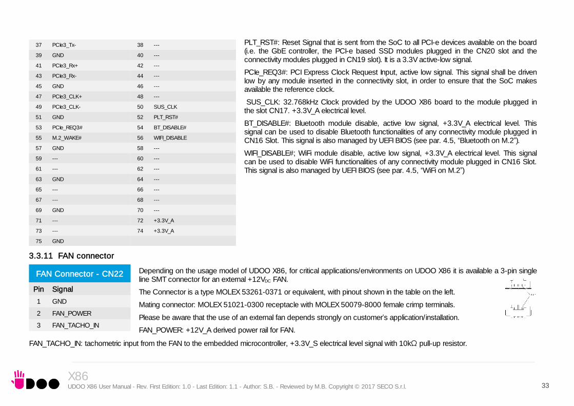
PLT_RST#: Reset Signal that is sent from the SoC to all PCI-e devices available on the board (i.e. the GbE controller, the PCI-e based SSD modules plugged in the CN20 slot and the connectivity modules plugged in CN19 slot)It is a 3.3V active-low signal.
PCIe_REQ0#: PCI Express Clock Request Input, active low signal. This signal shall be driven
M.2 SATA/PCI-e Slot - CN20
Pin Signal Pin Signal
1 --- 2 +3.3V_S
3 GND 4 +3.3V_S
5 GND 6 ---
7 --- 8 ---
9 --- 10 ---
11 GND
20 ---
21 --- 22 ---
23 --- 24 ---
25 --- 26 ---
27 GND 28 ---
29 PCIe1_Rx- 30 ---
31 PCIe1_Rx+ 32 ---
33 GND 34 ---
35 PCIe1_Tx- 36 ---
37 PCIe1_Tx+ 38 ---
39 GND 40 ---
41 SATA0_Rx+/PCIe0_Rx- 42 ---
43 SATA0_Rx-/PCIe0_Rx+ 44 ---
45 GND 46 ---
47 SATA0_Tx-/PCIe0_Tx- 48 ---
49 SATA0_Tx+/PCIe0_Tx+ 50 PLT_RST#
51 GND 52 PCIE_REQ0#
53 PCIe0_Clock- 54 ---
55 PCIe0_Clock+ 56 ---
57 GND 58 ---

X86 UDOO X86 User Manual - Rev. First Edition: 1.0 - Last Edition: 1.1 - Author: S.B. - Reviewed by M.B. Copyright © 2017 SECO S.r.l. 32
low by any module inserted in the connectivity slot, in order to ensure that the SoC makes
available the reference clock.
CONFIG_1: Configuration input signal, +3.3V_S signal with 10kΩ pull-up. This signal is necessary to switch between the S-ATA and the PCI-e signals on the pins 41/43/47/49 of connector CN20. When CONFIG_1 signal is high, then PCI-e x 2 interface is available on connector CN20. When the signal is driven low, then SATA interface will be available. The selection is automatic, since according to M.2 specifications for Socket2 SSD modules, CONFIG_1 signal must be low for SSD based modules and high for PCI-e based modules.
The PCI-e x2 interface can be used also for different purposes other than SSD modules, but it is important that the CONFIG_1 signal is driven properly (it can be left unconnected on PCI-e
based modules, due to the presence of the pull-up resistor on the platform).
3.3.10 M.2 Connectivity Slot: Socket 1 Key E Type 2230
It is possible to increase the connectivity of the UDOO X86 board by using M.2 Socket 1 Key E connectivity modules (i.e. modules with functionalities like WiFi + Bluetooth).
The connector used for the M.2 Connectivity slot is CN19, which is a standard 75 pin M.2 Key E connector, type LOTES p/n APCI0076-P001A, H=4.2mm, with the pinout shown in the table on the left.
On the UDOO X86 board there is also a Threaded Spacer which allows the placement of M.2 Socket 1 Key E connectivity modules in 2230 size.
Here following the signals related to this connectivity interface:
USB_P4+/USB_P4-: USB 2.0 Port #4 differential pair.
PCIe3_TX+/PCIe3_TX-: PCI Express lane #3, Transmitting Output Differential pair
PCIe3_RX+/PCIe3_RX-: PCI Express lane #3, Receiving Input Differential pair
PCIe3_Clock+ / PCIe3_Clock-: PCI Express Reference Clock for lane #3, Differential Pair
M.2_WAKE#: Board’s Wake Input, 3.3V_A active low signal. It must be externally driven by the Connectivity module plugged in the slot when it requires waking up the system.
59 --- 60 ---
61 --- 62 ---
63 --- 64 ---
65 --- 66 ---
67 --- 68 ---
69 CONFIG_1 70 +3.3V_S
71 GND 72 +3.3V_S
73 GND 74 +3.3V_S
75 ---
M.2 Connectivity Slot - CN19
Pin Signal Pin Signal
1 GND 2 +3.3V_A
3 USB_P4+ 4 +3.3V_A
5 USB_P4- 6 ---
7 GND 8 ---
9 --- 10 ---
11 --- 12 ---
13 --- 14 ---
15 --- 16 ---
17 --- 18 GND
19 --- 20 ---
21 --- 22 ---
23 ---
32 ---
33 GND 34 ---
35 PCIe3_Tx+ 36 ---
X86 UDOO X86 User Manual - Rev. First Edition: 1.0 - Last Edition: 1.1 - Author: S.B. - Reviewed by M.B. Copyright © 2017 SECO S.r.l. 33
PLT_RST#: Reset Signal that is sent from the SoC to all PCI-e devices available on the board (i.e. the GbE controller, the PCI-e based SSD modules plugged in the CN20 slot and the connectivity modules plugged in CN19 slot). It is a 3.3V active-low signal.
PCIe_REQ3#: PCI Express Clock Request Input, active low signal. This signal shall be driven low by any module inserted in the connectivity slot, in order to ensure that the SoC makes available the reference clock.
SUS_CLK: 32.768kHz Clock provided by the UDOO X86 board to the module plugged in the slot CN17. +3.3V_A electrical level.
BT_DISABLE#: Bluetooth module disable, active low signal, +3.3V_A electrical level. This signal can be used to disable Bluetooth functionalities of any connectivity module plugged in CN16 Slot. This signal is also managed by UEFI BIOS (see par. 4.5, “Bluetooth on M.2”).
WIFI_DISABLE#; WiFi module disable, active low signal, +3.3V_A electrical level. This signal can be used to disable WiFi functionalities of any connectivity module plugged in CN16 Slot. This signal is also managed by UEFI BIOS (see par. 4.5, “WiFi on M.2”)
3.3.11 FAN connector
Depending on the usage model of UDOO X86, for critical applications/environments on UDOO X86 it is available a 3-pin single line SMT connector for an external +12VDC FAN.
The Connector is a type MOLEX 53261-0371 or equivalent, with pinout shown in the table on the left.
Mating connector: MOLEX 51021-0300 receptacle with MOLEX 50079-8000 female crimp terminals.
Please be aware that the use of an external fan depends strongly on customer’s application/installation.
FAN_POWER: +12V_A derived power rail for FAN.
FAN_TACHO_IN: tachometric input from the FAN to the embedded microcontroller, +3.3V_S electrical level signal with 10kΩ pull-up resistor.
37 PCIe3_Tx- 38 ---
39 GND 40 ---
41 PCIe3_Rx+ 42 ---
43 PCIe3_Rx- 44 ---
45 GND 46 ---
47 PCIe3_CLK+ 48 ---
49 PCIe3_CLK- 50 SUS_CLK
51 GND 52 PLT_RST#
53 PCIe_REQ3# 54 BT_DISABLE#
55 M.2_WAKE# 56 WIFI_DISABLE
57 GND 58 ---
59 --- 60 ---
61 --- 62 ---
63 GND 64 ---
65 --- 66 ---
67 --- 68 ---
69 GND 70 ---
71 --- 72 +3.3V_A
73 --- 74 +3.3V_A
75 GND
FAN Connector - CN22
Pin Signal
1 GND
2 FAN_POWER
3 FAN_TACHO_IN

X86 UDOO X86 User Manual - Rev. First Edition: 1.0 - Last Edition: 1.1 - Author: S.B. - Reviewed by M.B. Copyright © 2017 SECO S.r.l. 34
3.3.12 UDOO Bricks connector
This connector, managed by the Intel® Curie microcontroller, allows augmenting features offered by the UDOO X86 board, by adding the UDOO Bricks external sensor modules.
The connector used is type MOLEX p/n 53398-0571 or equivalent, with the pinout shown in the table on the left.
Mating connector: MOLEX 51021-0500 receptacle with MOLEX 50079-8000 female crimp terminals.
ALERT#: I2C Bus Alert. Input Signal, electrical level +3.3V_C. It is managed through the Intel® Curie Sensor Subsystem’s GPIO #0
C_SDA0: I2C data line. Bidirectional signal, electrical level +3.3V_C with 10kΩ pull-up resistor. It is managed by the Intel® Curie Sensor Subsystem’s I2C port #0
C_SCL0: I2C clock line. Bidirectional signal, electrical level +3.3V_A with 10kΩ pull-up resistor. It is managed by the Intel® Curie Sensor Subsystem’s I2C port #0
3.3.13 SPI Header
This pin header, managed by the Intel® Curie microcontroller, has been implemented in order to allow the compatibility with existing Arduino sketches.
The connector, CN16 is an internal 10-pin standard right angle male pin header, p 2.54 mm, h= 6.1mm.
SPI_MISO: SPI Master In Slave Out input signal, electrical level +5V_C. It is managed through the Intel® Curie SPI master port #1
SPI_MOSI: SPI Master Out Slave In output signal, electrical level +5V_C. It is managed through the Intel® Curie SPI master port #1
SPI_CLK: SPI Clock output signal electrical level +5V_C. It is managed through the Intel® Curie SPI master port #1
RESET: Sketch reset input signal, electrical 5V_C
3.3.14 ARDUINO interface + expansion connectors
On four dedicated female headers p.2.54mm are realised both the Arduino 101 interface (managed by the Intel® Curie microcontroller) and the expansion interface, managed by the Intel® Braswell SoCs.
On the “internal” rows of these headers is implemented the Arduino interface, while on the “external” rows are available the expansion interfaces.
This will allow the plugging of Arduino 101-compatible sketches on these connectors, while leaving the further expansion interfaces free for use.
UDOO Bricks connector CN24
Pin Signal
1 +3.3V_C
2 ALERT#
3 C_SDA0
4 C_SCL0
5 GND
SPI Header - CN16
Pin Signal Pin Signal
1 SPI_MISO 2 5V_C
3 SPI_CLK 4 SPI_MOSI
5 RESET 6 GND

X86 UDOO X86 User Manual - Rev. First Edition: 1.0 - Last Edition: 1.1 - Author: S.B. - Reviewed by M.B. Copyright © 2017 SECO S.r.l. 35
Arduino / Expansion Socket #1 - CN12
Expansion side Arduino 101 Side
Pin Signal Pin Signal
2 SPDIF_OUT 1 IO14_NEW
4 SDIO_CLK 3 +3.3V_C
6 SDIO_CMD 5 RST_SKETCH
8 SDIO_DAT0 7 +3.3V_C
10 SDIO_DAT1 9 +5V_C
12 SDIO_DAT2 11 GND
14 SDIO_DAT3 13 GND
16 SDIO_WAKE# 15 +12V_A
Arduino / Expansion Socket #2 - CN13
Arduino 101 side Expansion Side
Pin Signal Pin Signal
19 AD5_SCL 20 1.8V_A
17 AD5_SDA 18 GND
15 --- 16 PLT_RST#
13 GND 14 LPC_SERIRQ#
11 IO13/SCK 12 LPC_CLK
9 IO12/MISO 10 LPC_FRAME#
7 IO11/MOSI 8 LPC_AD3
5 IO10/SS 6 LPC_AD2
3 IO9/PWM3 4 LPC_AD1
1 IO8 2 LPC_AD0 Arduino / Expansion Socket #3- CN14
Expansion side Arduino 101 Side
Pin Signal Pin Signal
2 TS_I2C_SDA 1 AD5_SCL
4 TS_I2C_SCL 3 AD5_SDA
6 TS_INT# 5 AD3
8 TS_RST# 7 AD2
10 I2C0_SDA 9 AD1
12 I2C0_SCL 11 AD0
Arduino / Expansion Socket #4 - CN15
Arduino 101 side Expansion Side
Pin Signal Pin Signal
15 IO7 16 UART2_RXD
13 IO6/PWM2 14 UART2_TXD
11 IO5/PWM1 12 UART2_CTS#
9 IO4 10 UART2_RTS#
7 IO3/PWM0 8 UART1_RXD
5 IO2 6 UART1_TXD
3 IO1/TXD 4 UART1_CTS#
1 IO0/RXD 2 UART1_RTS#

X86 UDOO X86 User Manual - Rev. First Edition: 1.0 - Last Edition: 1.1 - Author: S.B. - Reviewed by M.B. Copyright © 2017 SECO S.r.l. 36
The Intel® Curie microcontroller is connected to the Intel® Braswell via an internal USB. It's exactly the same thing as having an Arduino 101 board attached via USB to a standard PC.
It is therefore possible refer to Arduino 101 documentation for a description of related signals, and the way to use them.
Here following the description of the “expansion” signals available on these connectors:
SPDIF_OUT: Realtek ALC283 S/PDIF Out signal, 12mA@75Ω driving capability.
SDIO_CLK: Intel® Braswell SD/MMC Port #2 Clock line, 1.8V_A electrical level output signal. To be used exclusively as a GPIO signal.
SDIO_CMD: Intel® Braswell SD/MMC Port #2 Command line, 1.8V_A electrical level bidirectional signal. To be used exclusively as a GPIO signal.
SDIO_DAT[0..3]: Intel® Braswell SD/MMC Port #2 Data bus. 1.8V_A electrical level bidirectional signals. To be used exclusively as GPIO signals.
SDIO_WAKE#: Wake capable input signal, 1.8V_A electrical level input.
TS_I2C_SDA: Touch-screen dedicated I2C Bus data line. Bidirectional signal, electrical level +1.8V_A. It is managed by Intel® Braswell SoCs’ I2C port #5.
TS_I2C_SCL: Touch-screen dedicated I2C Bus clock line. Bidirectional signal, electrical level +1.8V_A. It is managed by Intel® Braswell SoCs’ I2C port #5.
TS_INT#: +1.8V_A electrical level input. This signal can be used to serve the interrupt request of an eventual external Touch Screen connected to the dedicated I2C interface. It is also possible to use this signal as a GPIO.
TS_RST#: +1.8V_A electrical level output. This signal can be used to drive a reset of an eventual external Touch Screen connected to the dedicated I2C interface. It is also possible to use this signal as a GPIO.
I2C0_SDA: I2C Bus data line. Bidirectional signal, electrical level +1.8V_A. It is managed by Intel® Braswell SoCs’ I2C port #0.
I2C0_SCL: I2C Bus clock line. Bidirectional signal, electrical level +1.8V_A. It is managed by Intel® Braswell SoCs’ I2C port #0.
PLT_RST#: Reset Signal that is sent from the SoC to all PCI-e devices available on the board (i.e. the GbE controller, the PCI-e based SSD modules plugged in the CN20 slot and the connectivity modules plugged in CN19 slot). 3.3V active-low output signal.
LPC_SERIRQ#: LPC Serialised IRQ request, bidirectional line, +3.3V_S electrical level. It is managed by Intel® Braswell SoCs’ LPC bridge.
LPC_CLK: LPC Clock output, +3.3V_S electrical level 25MHz clock. It is managed by Intel® Braswell SoCs’ LPC bridge.
LPC_FRAME#: LPC Frame indicator, active low output line, +3.3V_S electrical level. It is managed by Intel® Braswell SoCs’ LPC bridge
LPC_AD[0..3]: LPC address, command and data bus, bidirectional signal, +3.3V_S electrical level. It is managed by Intel® Braswell SoCs’ LPC bridge
UART2_RXD: UART Interface, Serial data Receive (input) line, 1.8V_A electrical level. It is managed by Intel® Braswell SoCs’ High Speed UART Controller #2.
UART2_TXD: UART Interface, Serial data Transmit (output) line, 1.8V_A electrical level. It is managed by Intel® Braswell SoCs’ High Speed UART Controller #2.
UART2_CTS#: UART Interface, Handshake signal, Clear to Send (Input) line, 1.8V_A electrical level. It is managed by Intel® Braswell SoCs’ High Speed UART Controller #2.

X86 UDOO X86 User Manual - Rev. First Edition: 1.0 - Last Edition: 1.1 - Author: S.B. - Reviewed by M.B. Copyright © 2017 SECO S.r.l. 37
UART2_RTS#: UART Interface, Handshake signal, Request to Send (output) line, 1.8V_A electrical level. It is managed by Intel® Braswell SoCs’ High Speed UART Controller #2.
UART1_RXD: UART Interface, Serial data Receive (input) line, 1.8V_A electrical level. It is managed by Intel® Braswell SoCs’ High Speed UART Controller #1.
UART1_TXD: UART Interface, Serial data Transmit (output) line, 1.8V_A electrical level. It is managed by Intel® Braswell SoCs’ High Speed UART Controller #1.
UART1_CTS#: UART Interface, Handshake signal, Clear to Send (Input) line, 1.8V_A electrical level. It is managed by Intel® Braswell SoCs’ High Speed UART Controller #1.
UART1_RTS#: UART Interface, Handshake signal, Request to Send (output) line, 1.8V_A electrical level. It is managed by Intel® Braswell SoCs’ High Speed UART Controller #1.
3.3.15 IR Receiver
The UDOO X86 board embeds an IR receiver, which allows using a remote control when the board is placed in an enclosure (like, i.e., on Set Top Boxes).
The Infrared Receiver is SMD Type, p/n TSOP75238TR, and works with 38kHz carrier frequency.
The IR port is managed by the embedded microcontroller.

X86 UDOO X86 User Manual - Rev. First Edition: 1.0 - Last Edition: 1.1 - Author: S.B. - Reviewed by M.B. Copyright © 2017 SECO S.r.l. 38
Chapter 4.
InsydeH2O setup Utility Main setup menu Advanced menu Security menu Power menu Boot menu Exit menu

X86 UDOO X86 User Manual - Rev. First Edition: 1.0 - Last Edition: 1.1 - Author: S.B. - Reviewed by M.B. Copyright © 2017 SECO S.r.l. 39
4.1 InsydeH2O setup Utility
Basic setup of the board can be done using Insyde Software Corp. “InsydeH2O Setup Utility”, that is stored inside an onboard SPI Serial Flash.
It is possible to access to InsydeH2O Setup Utility by pressing the <ESC> key after System power up, during POST phase. On the splash screen that will appear, select “SCU” icon.
On each menu page, on left frame are shown all the options that can be configured.
Grayed-out options are only for information and cannot be configured.
Only options written in blue can be configured. Selected options are highlighted in white.
Right frame shows the key legend.
KEY LEGEND:
← / → Navigate between various setup screens (Main, Advanced, Security, Power, Boot...)
↑ / ↓ Select a setup item or a submenu
<F5> / <F6> <F5> and <F6> keys allows to change the field value of highlighted menu item
<F1> The <F1> key allows displaying the General Help screen.
<F9> <F9> key allows loading Setup Defaults for the board. After pressing <F9> UEFI BIOS Setup utility will request for a confirmation, before saving and exiting. By pressing <ESC> key, this function will be aborted
<F10> <F10> key allows save any changes made and exit Setup. After pressing <F10> key, UEFI BIOS Setup utility will request for a confirmation, before saving and exiting. By pressing <ESC> key, this function will be aborted
<ESC> <Esc> key allows discarding any changes made and exit the Setup. After pressing <ESC> key, UEFI BIOS Setup utility will request for a confirmation, before discarding the changes. By pressing <Cancel> key, this function will be aborted
<ENTER> <Enter> key allows to display or change the setup option listed for a particular setup item. The <Enter> key can also allow display the setup sub- screens.

X86 UDOO X86 User Manual - Rev. First Edition: 1.0 - Last Edition: 1.1 - Author: S.B. - Reviewed by M.B. Copyright © 2017 SECO S.r.l. 40
4.2 Main setup menu
When entering the Setup Utility, the first screen shown is the Main setup screen. It is always possible to return to the Main setup screen by selecting the Main tab.
In this screen, are shown details regarding UEFI BIOS version, Processor type, Bus Speed and memory configuration.
Only two options can be configured:
4.2.1 System Time / System Date
Use this option to change the system time and date. Highlight System Time or System Date using the <Arrow> keys. Enter new values directly through the keyboard, or using + / - keys to increase / reduce displayed values. Press the <Enter> key to move between fields. The date must be entered in MM/DD/YY format. The time is entered in HH:MM:SS format.
Note: The time is in 24-hour format. For example, 5:30 A.M. appears as 05:30:00, and 5:30 P.M. as 17:30:00.
The system date is in the format mm/dd/yyyy.

X86 UDOO X86 User Manual - Rev. First Edition: 1.0 - Last Edition: 1.1 - Author: S.B. - Reviewed by M.B. Copyright © 2017 SECO S.r.l. 41
4.3 Advanced menu
4.3.1 Boot configuration submenu
4.3.2 Security configuration (TXE) submenu
Menu Item Options Description
Boot Configuration See submenu Configures settings for Boot Phase
Security configuration See submenu Trusted Execution Environment Security Configurations
Video Configuration See submenu Configures the options for video section
Chipset Configuration See submenu Configure Chipset’s parameters
ACPI Table / Features Control See submenu Configures the parameters for ACPI management
SATA Configuration See submenu Select the SATA controller and hard disk drive type installed in the system
Console Redirection See submenu Configures the parameters for Console redirection
POST Hot Key See submenu Configure POST Hot Keys
Other Configuration See submenu Other parameters settings
Menu Item Options Description
OS Selection Windows / Android Configures the UEFI BIOS in order to support properly Windows or Android OS.
Numlock On / Off Allows to choose whether NumLock Key at system boot must be turned On or Off
Menu Item Options Description
TXE HMRFP0 Disabled / Enabled Enable this option to remove temporarily the flash protection, in order to program the Intel® TXE region
TXE Firmware update Disabled / Enabled Enable this option to require a re-flashing of TXE Firmware Image
TXE EOP Message Disabled / Enabled Send EOP (End of POST) Message before entering OS
TXE Unconfiguration Perform Yes / No Only selectable on CPUs with the TXE feature. Allows to revert TXE settings to the factory defaults
Measured boot Disabled / Enabled Enable or disable the measured boot, which provide to antimalware software a trusted log of all boot components that started before the antimalware software itself.

X86 UDOO X86 User Manual - Rev. First Edition: 1.0 - Last Edition: 1.1 - Author: S.B. - Reviewed by M.B. Copyright © 2017 SECO S.r.l. 42
4.3.3 Video configuration submenu
Menu Item Options Description
HDMI Disabled / Enabled Enable / Disable the HDMI video port
Mini DisplayPort 1 Disabled / Enabled Enable / Disable the miniDP video port #1 (CN5)
Mini DisplayPort 2 Disabled / Enabled Enable / Disable the miniDP video port #2 (CN4)
Integrated Graphics Device Disabled / Enabled
Enabled: enable Integrated Graphics Device (IGD) when selected as the Primary Video Adaptor. Disabled: always disable IGD. Warning: when the IGD is disabled, there will be no video output at all (unless there is an external PCIe graphic card selected as Primary Display) and restoring UEFI BIOS options to default values will be possible only by moving blindly in the setup menu.
Primary Display Auto / IGD / PCIe Select which between IGD or external PCI-e Graphic Controller should be the Primary display
RC6(Render Standby) Disabled / Enabled Permits to enable the render standby features, which allows the onboard graphics entering in standby mode to decrease power consumption
PAVC Disabled / LITE Mode / SERPENT Mode
Allows enabling the hardware acceleration of decoding of Protected Audio Video streams.
When not disabled, it is possible to choose between LITE encryption and SERPENT encryption modes.
PR3 Disabled / Enabled Enable / Disable PAVP PR3 mode
Unsolicited Attack Override Disabled / Enabled Enable / Disable PAVP Unsolicited Attack Override
GTT Size 2MB / 4MB / 8MB Select the GTT (Graphics Translation Table) Size
Aperture Size 128MB / 256MB / 512MB Use this item to set the total size of Memory that must be left to the GFX Engine
IGD - DVMT Pre-Allocated
32M / 64M / 96M / 128M / 160M / 192M / 224M / 256M / 288M / 320M / 352M / 384M / 416M / 448M / 480M / 512M
Select DVMT5.0 Pre-Allocated (Fixed) Graphics Memory size used by the Internal Graphic Device
IGD - DVMT Total Gfx Mem 128M / 256M / MAX Select the size of DVMT (Dynamic Video Memory) 5.0 that the Internal Graphics Device will use
IGD Turbo Auto / Enabled / Disabled Enable or Disable IGD Turbo mode
Power Meter Lock Disabled / Enabled Enable or disable the Power Meter lock Functionality
WOPCMSZ 1MB / 2MB / 4MB / 8MB Select a size for WOPCM

X86 UDOO X86 User Manual - Rev. First Edition: 1.0 - Last Edition: 1.1 - Author: S.B. - Reviewed by M.B. Copyright © 2017 SECO S.r.l. 43
4.3.4 Chipset configuration submenu
4.3.4.1 USB configuration submenu
4.3.4.2 Audio configuration submenu
Menu Item Options Description
USB Configuration See submenu Configures USB Section
Audio Configuration See submenu Configures Audio Section
LPSS & SCC Configuration See submenu Configures LPSS (Low-Power Sub-System, i.e. DMA, PWM, UART and I2C interfaces) and SCC (Storage Control Cluster) devices
Miscellaneous Configuration See submenu Enable / Disable Misc. features
PCI Express Configuration See submenu PCI Express Configuration Settings
Menu Item Options Description
USB BIOS Support Disabled / Enabled / UEFI Only
Sets the support for USB keyboard / mouse / storage under UEFI and DOS environment. When set to UEFI only, then it will support exclusively UEFI environment.
xHCI Controller Disabled / Enabled Enable/Disable the xHCI Controller PreBoot Support
Port#0 (USB3.0 Front Panel CN6) Disabled / Enabled Enable / Disable USB Port #0, which is available on USB 3.0 connector CN6 in Front Panel Side
Port#1 (USB3.0 Front Panel CN7) Disabled / Enabled Enable / Disable USB Port #1, which is available on USB 3.0 connector CN7 in Front Panel Side
Port#2 (USB3.0 Rear Panel CN8) Disabled / Enabled Enable / Disable USB Port #2, which is available on USB 3.0 connector CN8 in Rear Panel Side
Port#3 (Arduino 101) Disabled / Enabled Enable / Disable USB Port #3, which is used for the communications with Intel® Curie microcontroller implementing the Arduino 101 interface
Port#4 (USB2.0 M.2 Type 2230 CN19) Disabled / Enabled Enable / Disable USB Port #4, which is available on M.2 Connectivity Slot CN19
Menu Item Options Description
Audio Controller Disabled / Enabled Controls the detection of the HD Audio Controller Disabled: the Audio controller will be unconditionally Disabled Enabled: the Audio controller will be unconditionally Enabled
Azalia HDMI Codec Disabled / Enabled Enable or Disable internal HDMI Codec for audio
Mute HDA Amplifier Disabled / Enabled Force the HDA amplifier to mute, when enabled.

X86 UDOO X86 User Manual - Rev. First Edition: 1.0 - Last Edition: 1.1 - Author: S.B. - Reviewed by M.B. Copyright © 2017 SECO S.r.l. 44
4.3.4.3 LPSS & SCC configuration submenu
4.3.4.4 Miscellaneous Configuration submenu
Menu Item Options Description
Hide unused LPSS devices Enable / Disable Hide Unused LPSS & SCC ACPI Devices.
LPSS & SCC Auto Switch Enable / Disable Auto switches LPSS and SCC devices from ACPI mode to PCI mode when the OS doesn’t support ACPI mode.
ACPI GPIO Devices Support Enabled (ACPI) / Disabled Enable or Disable GPIO ACPI Devices Support
eMMC Support Disabled / Enabled (PCI) / Enabled (ACPI)
Disable the eMMC Support, or enables it in PCI or ACPI Mode.
SD Card Support Disabled / Enabled (PCI) / Enabled (ACPI)
Disable the SD Card Support, or enables it in PCI or ACPI Mode.
DMA #1 Support Disabled / Enabled (PCI) / Enabled (ACPI)
Allows to enable first DMA Channel, which onboard is used to support the UART interfaces
HSUART #1 Disabled / Enabled Can be changed only when “DMA #1 Support” is not Disabled. Enable / Disable the UART interface #1 available on connector CN15
HSUART #2 Disabled / Enabled Can be changed only when “DMA #1 Support” is not Disabled. Enable / Disable the UART interface #2 available on connector CN15
DMA #2 Support Disabled / Enabled (PCI) / Enabled (ACPI)
Allows to enable second DMA Channel, which on-board is used to support the I2C Channel
I2C #0 - CN14 pin 10/12 Disabled / Enabled Can be changed only when “DMA #2 Support” is not Disabled. Enable / Disable the I2C port #0 available on connector CN14, pins 10/12
I2C #5 - CN14 pin 2/4 Disabled / Enabled Can be changed only when “DMA #2 Support” is not Disabled. Enable / Disable the I2C port #5 available on connector CN14, pins 2/4
Menu Item Options Description
RTC Lock Enabled / Disabled When Enabled, bytes 38h-3F8h in the lower/upper 128-byte bank of RTC RAM will be locked.
BIOS Lock Enabled / Disabled Enable or disable UEFI BIOS SPI region write protect.
LPC Support Enabled / Disabled Enable or disable the LPC support on connector CN13 (pins 2 / 4 / 6 / 8 / 10 / 12 / 14). When disabled, the LPC dedicated pins will be available as GPIOs

X86 UDOO X86 User Manual - Rev. First Edition: 1.0 - Last Edition: 1.1 - Author: S.B. - Reviewed by M.B. Copyright © 2017 SECO S.r.l. 45
4.3.4.5 PCI Express configuration submenu
4.3.4.5.1 PCI Express Root Port #x configuration submenus
4.3.5 ACPI Table/features submenu
4.3.6 SATA configuration submenu
Menu Item Options Description
PCI Express Port x2 - M.2 on CN20 x2 slot PCI Express Port x1 - Internal LAN PCI Express Port 3 - M.2 Slot CN19
See submenu
Menu Item Options Description
PCI Express Root Port #1 PCI Express Root Port #3 PCI Express Root Port #4
Disabled / Enabled Enable or Disable single PCI Express Root Port #x. PCI Express Root Port #3 is internally connected to the Gigabit Ethernet Controller. Disabling this port will result in disabling the corresponding Ethernet interface.
PCIe Speed Auto / Gen1 / Gen2 Set PCI-e ports link speed/capability.
Menu Item Options Description
FACP - RTC S4 wakeup Enabled / Disabled Enable or disable FACP (Fixed ACPI Description Table) support for S4 wakeup from RTC
FACP - Preferred PM Profile Auto / Desktop / Mobile This Option sets the preferred power management profile in ACPI Fixed ACPI Description Table
DSDT - ACPI S3 Support Enabled / Disabled Enable or disable DSDT (Differentiated System Description Table) support for ACPI S3 State
DSDT - ACPI S4 Support Enabled / Disabled Enable or disable DSDT (Differentiated System Description Table) support for ACPI S4 State
WDAT/WDRT - TCO Watchdog Support Enabled / Disabled Enable or disable the TCO Watchdog Support
Menu Item Options Description
SATA Controller Enabled / Disabled Disabled: Disables SATA Controller. All following items will be disabled Enabled: Enables SATA Controller
SATA Interface Speed Gen1 / Gen2 / Gen3 Select SATA speed
SATA Port 0 / SATA Port 1 Enabled / Disabled Enables or disable SATA Port #0 (M.2 Slot CN17) / SATA Port #1 (SATA Connector CN18).
Serial ATA Port 0 / 1 Shows information related to eventual devices connected to SATA ports 0 or 1

X86 UDOO X86 User Manual - Rev. First Edition: 1.0 - Last Edition: 1.1 - Author: S.B. - Reviewed by M.B. Copyright © 2017 SECO S.r.l. 46
4.3.7 Console Redirection submenu
Menu Item Options Description
Console Serial Redirect Enabled / Disabled Enable or disable Console redirection. When enabled, all the submenus of the following paragraph will appear
Terminal Type VT_100 / VT_100+ / VT_UTF8 / PC_ANSI
Set Console Redirection terminal type
Baud rate 115200 / 57600 / 38400 / 19200 / 9600 / 4800 / 2400 / 1200
Set Console Redirection baud rate
Data Bits 7 bits / 8 bits Set Console Redirection data bits
Parity None / Even / Odd Set Console Redirection parity bits
Stop Bits 1 bit / 2 bits Set Console Redirection stop bits
Flow Control None RTS/CTS XON/XOFF
Set Console Redirection flow control type
Information Wait Time 0 Seconds / 2 Seconds / 5 Seconds / 10 Seconds / 30 Seconds
Set Console Redirection port information display time
C.R. After Post Yes / No Console Redirection continues to work even after Bios POST.
AutoRefresh Enabled / Disabled When this feature is enabled, the screen will auto refresh once after detecting the connection of a remote terminal
FailSafeBaudRate Enabled / Disabled This feature will auto detect remote terminal baud rate and connect C.R serial device with detected baud rate
ACPI SPCR Table Enabled / Disabled Serial Port Console Redirection Table. When this feature is enabled, the SPCR table will be add-into ACPI tables.
PCI_HS_UART 0:30:3 PCI_HS_UART 0:30:4
See submenus

X86 UDOO X86 User Manual - Rev. First Edition: 1.0 - Last Edition: 1.1 - Author: S.B. - Reviewed by M.B. Copyright © 2017 SECO S.r.l. 47
4.3.7.1 PCI HS_UART 0:30:x submenus
Menu Item Options Description
Port Enabled Disabled / Enabled Enable or Disable single PCI HS_UART Port #x.
UseGlobalSetting Disabled / Enabled When this item is enabled, the corresponding HS_UART will use the global settings. Otherwise, it will be possible to set individually the following items
Terminal Type VT_100 / VT_100+ / VT_UTF8 / PC_ANSI
Set HS_UART #x terminal type
Baud rate 115200 / 57600 / 38400 / 19200 / 9600 / 4800 / 2400 / 1200
Set HS_UART #x baud rate
Data Bits 7 bits / 8 bits Set HS_UART #x data bits
Parity None / Even / Odd Set HS_UART #x parity bits
Stop Bits 1 bit / 2 bits Set HS_UART #x stop bits
Flow Control None RTS/CTS XON/XOFF
Set HS_UART #x flow control type

X86 UDOO X86 User Manual - Rev. First Edition: 1.0 - Last Edition: 1.1 - Author: S.B. - Reviewed by M.B. Copyright © 2017 SECO S.r.l. 48
4.3.8 POST Hot Key submenu
4.3.9 Other configuration submenu
Menu Item Options Description
Device Manager Hot Key N/A / F1 / F2 / F3 / F4 / F5 / F6 / F7 / F8 / F9 / F10 / F11 / F12 / DEL / ESC
Allows assigning an Hot key to enter the Device Manager utility during POST phase
Setup Utility Hot Key N/A / F1 / F2 / F3 / F4 / F5 / F6 / F7 / F8 / F9 / F10 / F11 / F12 / DEL / ESC
Allows assigning an Hot key to enter the Setup utility during POST phase
Boot Manager Hot Key N/A / F1 / F2 / F3 / F4 / F5 / F6 / F7 / F8 / F9 / F10 / F11 / F12 / DEL / ESC
Allows assigning an Hot key to enter the Boot Manager utility during POST phase
Boot From File Hot Key N/A / F1 / F2 / F3 / F4 / F5 / F6 / F7 / F8 / F9 / F10 / F11 / F12 / DEL / ESC
Allows assigning an Hot key to enter the Boot From File utility during POST phase
Front Page Hot Key N/A / F1 / F2 / F3 / F4 / F5 / F6 / F7 / F8 / F9 / F10 / F11 / F12 / DEL / ESC
Allows assigning an Hot key to enter the Front Page Screen during POST phase
Menu Item Options Description
Win7 Keyboard/Mouse Support Enabled / Disabled Enable or disable the support for USB Keyboard and Mouse in Windows 7 even in absence of the xHCI driver.
Force Legacy Free Enabled / Disabled When enabled, this item will force the Legacy Free mode (it will disable the KBC).

X86 UDOO X86 User Manual - Rev. First Edition: 1.0 - Last Edition: 1.1 - Author: S.B. - Reviewed by M.B. Copyright © 2017 SECO S.r.l. 49
4.4 Security menu
Menu Item Options Description
TPM Availability Available / Hidden When this item is set to Hidden, the TPM will not be shown to the OS
TPM Operation No operation Disabled Enabled
Enable or Disable Storage Hierarchy and Endorsement Hierarchy
Clear TPM Yes / No Clear TPM. Removes all TPM context associated with a specific Owner.
Set Supervisor Password Install or Change the password for supervisor. Length of password must be greater than one character.
Power on Password Enabled / Disabled Available only when Supervisor Password has been set. Enabled: System will ask to input a password during P.O.S.T. phase. Disabled: system will ask to input a password only for entering Setup utility
User Access Level View Only Full
Available only when Supervisor Password has been set. View Only: User can view SETUP menu items but cannot change any item. Full: User has full access to SETUP menu and can change all items, except the Supervisor Password
Set User Password Install or Change the password for User. Length of password must be greater than one character.
Clear User Password Selecting this option will clear the User password without having to type the current password. A supervisor can use this to clear a user password without knowing it.

X86 UDOO X86 User Manual - Rev. First Edition: 1.0 - Last Edition: 1.1 - Author: S.B. - Reviewed by M.B. Copyright © 2017 SECO S.r.l. 50
4.5 Power menu
Menu Item Options Description
Advanced CPU Control See submenu These items control various CPU parameters
EC Watchdog Configuration See submenu Embedded Controller Watchdog Configuration Settings
Thermal Zone configuration See submenu Thermal Zone Configuration: Active and Passive Cooling Settings.
Power Fail Resume Type Always ON Always OFF Last State
Determine the System Behavior after a power failure event. In case the option is “Always ON”, the board will start every time the power supply is present. When the option is “Always OFF”, the board will not start automatically when the power supply returns.
went down: so, if the board was on, it will start again when the power returns, and will remain off if the board was in this state when the power went down. A CMOS Battery is required to support this feature, otherwise the chipset default setting is Always ON.
WiFi on M.2 Enabled / Disabled Enables or disables the WiFi capabilities of WiFi cards plugged into M.2 slot CN19.
Bluetooth on M.2 Enabled / Disabled Enables or disables the BT capabilities of BlueTooth cards plugged into M.2 slot CN19.
Instant OFF Enabled / Disabled In non-ACPI environments, this item will enable the system shut-down by a power button pressure.
Curie Power Management Enabled Wake Only Disabled
Enables or disables the system power-on and power-signal (CN13 pin 3, active low 20ms pulse). When disabled, When “Wake Only”
(S3/S4/S5, depending on OS configuration) and wake from it
Power on Intel Curie Enabled / Disabled If enabled, it will power-on the Arduino interface
Curie reset on Power On Enabled / Disabled When enabled, the system will automatically reset the Intel® -power state (S3/S4/S5)
Infrared Support Enabled Wake Only Disabled
Enables or disables the system power-on and power-off managed by the Infrared Remote Control. When disabled, the Infrared Receiver will be unconditionally disabled. When “Wake Only”, the Infrared Receiver will only be able to wake the system from S3/S4/S5 When enabled, the Infrared Receiver will be able both to put the system in a low power state (S3/S4/S5, depending on OS configuration) and wake from it
Wake on PME Enabled / Disabled Determines whether the system must wake up or not when the system power is off and occurs a PCI Power Management Enable wake-up event (e.g. to enable Wake on LAN feature).

X86 UDOO X86 User Manual - Rev. First Edition: 1.0 - Last Edition: 1.1 - Author: S.B. - Reviewed by M.B. Copyright © 2017 SECO S.r.l. 51
Wake on RTC from S5
Disabled By Every Day By Day of Month By Sleep Time By OS Utility
Auto wake up from S5 state, it can be set to happen “By Every Day”, “By Day of Month”, “By Sleep Time” or “By OS Utility”.
Wake from S5 time [hh:mm:ss]
This menu item is available only when “ Wake on RTC from S5” is set to “By Every Day” of “By Day of Month”.
Set time of the day when the board must wake up automatically
Day of month 1 ÷ 31 This menu item is available only when “Auto Wake on S5” is set to “By Day of Month” This is the help for the day field. Valid range is from 1 to 31. Error checking will be done against month/day/year combinations that are not supported. Use + / - to Increase / reduce
Wake from S5 after (seconds) 5 ÷ 44 This menu item is available only when “Auto Wake on S5” is set to “By Sleep Time” Set the number of seconds after which the board will wake up automatically

X86 UDOO X86 User Manual - Rev. First Edition: 1.0 - Last Edition: 1.1 - Author: S.B. - Reviewed by M.B. Copyright © 2017 SECO S.r.l. 52
4.5.1 Advanced CPU control submenu
Menu Item Options Description
Use XD Capability Enabled / Disabled Enable or disable processor XD (Execute Disable) capability, it allows to enable or disable the hardware feature needed for data execution prevention
Limit CPUID Max Value Enabled / Disabled
Set this option to enabled for use with older O.S. that are not able to manage the CPUID value higher than 03h, which was typical for Intel® Pentium 4 with Hyper Threading Technology
Leave disabled for newer O.S. able to manage actual CPUID value.
Bi-Directional PROCHOT# Enabled / Disabled PROCHOT# is the signal used to start thermal throttling. This signal can be driven by any processor cores’ to signal that the processor will begin thermal throttling. If bi-directional signaling is enabled, then external components can also drive PROCHOT# signal in order to start throttling.
VTX-2 Enabled / Disabled Enable or Disable Intel® Virtualization Technology, allowing hardware-assisted virtual machine management.
TM1 Enabled / Disabled Enable or Disable TM1 Thermal management modes.
Active Processor Cores 1 / 2 / ALL Number of cores to enable in each processor package. 1 means that multicore processing is disabled.
P-States (IST) Enabled / Disabled Enable or disable processor management of performance states (P-states)
Boot Performance Mode Max Performance Max Battery Auto
Only available when P-states are enabled Allows to select which performance state must be set by UEFI BIOS before starting OS loading.
Turbo Mode Enabled / Disabled Only available when P-states are enabled Enable processor Turbo Mode
C-States Enabled / Disabled Enable processor idle power saving states (C-States).
Enhanced C-States Enabled / Disabled Enable P-state transition to occur in combination with C-states.
Max C-States C1 / C6 / C7 Only available when C-states are enabled Allows selection of the maximum C-State that must be supported by the OS.

X86 UDOO X86 User Manual - Rev. First Edition: 1.0 - Last Edition: 1.1 - Author: S.B. - Reviewed by M.B. Copyright © 2017 SECO S.r.l. 53
4.5.2 EC Watchdog Configuration submenu
4.5.3 Thermal Zone configuration submenu
Menu Item Options Description
Watchdog Enabled / Disabled Enable or Disable the Watchdog
Watchdog Action System reset Power Button 1s Power Button 4s (shutdown)
This submenu is available only when “Watchdog” is set to Enabled. Specifies the action that must be performed when Watchdog timeout occurs. With System Reset, the module will reset itself With “Power Button 1s”, the system will simulate the pressure for 1 sec. of Power button, which will lead the O.S. to close all his tasks then shutdown. With “Power Button 1s”, the system will simulate the pressure for 1 sec. of Power button, which will lead to the immediate shutdown of the module
Delay to start (sec.) 0 ÷ 600 This item can be changed only when “Watchdog” is enabled. Seconds of delay before the watchdog timer starts counting
Timeout (sec.) 20 ÷ 600 This item can be changed only when “Watchdog” is enabled. Watchdog Timeout.
Menu Item Options Description
Critical temperature (°C) Disabled / 80 / 85 / 88 / 90 Above this temperature value, an ACPI aware OS performs a critical shutdown.
Hot temperature (°C) Disabled / 80 / 85 / 88 / 90 Above this temperature value, an ACPI aware OS hibernates the system.
Passive Cooling temperature (°C) Disabled / 70 / 75 / 80 / 85 Above this threshold, an ACPI aware OS will start to lower the CPU frequency.
AC0 Temperature (°C) Disabled / 65 / 70 / 75 / 80 / 85
Select the highest temperature above which the onboard fan must work always at Full Speed
AC1 Temperature (°C) Disabled / 55 / 60 / 65 / 70 / 75 / 80 / 85 / 90 / 95 / 100 / 105 / 110 / 115
Select the lowest temperature under which the onboard fan must be OFF.
FAN Duty Cycle (%) Above AC1 50 / 75 / 100 Use this item to set the Duty Cycle for the fan when the CPU temperature is between AC1 and AC0 threshold. Above AC0, the fan will run at full speed.

X86 UDOO X86 User Manual - Rev. First Edition: 1.0 - Last Edition: 1.1 - Author: S.B. - Reviewed by M.B. Copyright © 2017 SECO S.r.l. 54
4.6 Boot menu
Menu Item Options Description
Boot type Dual boot Type Legacy Boot Type UEFI Boot Type
Allows to select if the OS must be booted using Legacy Boot Mode, UEFI Boot mode or indifferently using both modalities (depending on the OS)
Quick Boot Enabled / Disabled Skip certain tests while booting. This will decrease the time needed to boot the system.
Quiet Boot Enabled / Disabled Disables or enables booting in Text Mode.
Display Boot Logo Enabled / Disabled Enable or display the visualization of a logo during Boot phase
Logo persistence Time (s) 0 ÷ 10 This submenu is available only when “Display Boot Logo” is set to Enabled. Forced wait time in seconds during the boot logo visualization. 0 means boot as fast as possible. Even with 0 wait time. UEFI OSes supporting BGRT table will display the logo while booting.
Display ESC Key Strings Enabled / Disabled Display or Hide the “ESC key” strings during the UEFI BIOS boot. Disabling this configuration, no information on how to enter Setup Configuration Utility will be displayed.
Network Stack Enabled / Disabled
This submenu is available only when “Boot Type” is set to “UEFI Boot type” or “Dual Boot type”. When enabled, this option will make available the following Network Stack services: Window 8 BitLocker Unlock UEFI IPv4 / IPv6 PXE Legacy PXE OpROM
PXE Boot Capability
Disabled UEFI : IPv4 UEFI : IPv6 UEFI : IPv4/IPv6
Legacy
This submenu is available only when “Network Stack” is Enabled Specifies the PXE (Preboot Execution Environment) Boot possibilities. When Disabled, Network Stack is supported For UEFI, it supports IPv4, IPv6 or both In Legacy mode, only Legacy PXE OpROM is supported
PXE Boot to LAN Enabled / Disabled This submenu is available only when “Boot Type” is set to “Legacy Boot type”. Disables or enables the possibility for the PXE to perform the boot from LAN.
Power Up in Standby Support Enabled / Disabled Disable or enable Power Up in Standby Support. The PUIS feature set allows devices to be powered-up in the Standby power management state to minimize inrush current at power-up and to allow the host to sequence the spin-up of devices.
Add Boot options First / Last / Auto Specifies the position in Boot Order for Shell, Network and Removable Disks

X86 UDOO X86 User Manual - Rev. First Edition: 1.0 - Last Edition: 1.1 - Author: S.B. - Reviewed by M.B. Copyright © 2017 SECO S.r.l. 55
ACPI selection Acpi1.0B / Acpi3.0 / Acpi4.0 / Acpi5.0
Using this menu item is possible to select to which specifications release the ACPI tables must be compliant.
USB Boot Enabled / Disabled Disables or enables booting from USB boot devices.
EFI/Legacy Device Order EFI device first Legacy device first Smart Mode
This submenu is available only when “Boot Type” is set to Dual Boot Type.
Determine if boot must happen first through EFI devices or through legacy devices, or in Smart Mode.
UEFI OS Fast Boot Enabled / Disabled This submenu is available only when “Boot Type” is set to UEFI Boot Type. If enabled, the system firmware does not initialize keyboard and check for firmware menu key.
USB Hot Key Support Enabled / Disabled Available only when “Boot Type” is set to UEFI Boot Type and “UEFI OS Fast Boot” is Enabled. Enable or disable the support for USB HotKeys while booting. This will decrease the time needed to boot the system
Timeout 0 ÷ 10 The number of seconds that the firmware will wait before booting the original default boot selection.
Automatic Failover Enabled / Disabled
When this item is enabled, if boot from the default device fails, then the system will attempt directly to boot from the next device on the Boot devices list
When this item is disabled, in case of failure from booting from the first boot device, then a Warning Message will pop up and subsequently enter into Firmware UI.
EFI See Submenu This submenu is available only when “Boot Type” is not set to “Legacy Boot type”. The submenu will show a list of EFI boot devices. Use F5 and F6 key to change order for boot priority.
Legacy See Submenu This submenu is available only when “Boot Type” is not set to “UEFI Boot type”.
Allows setting of Legacy Boot Order

X86 UDOO X86 User Manual - Rev. First Edition: 1.0 - Last Edition: 1.1 - Author: S.B. - Reviewed by M.B. Copyright © 2017 SECO S.r.l. 56
4.6.1 Legacy submenu
Menu Item Options Description
Boot Menu Normal / Advance When set to Normal, this submenu will allow configuring all possible options for Legacy boot. When set to Advance, it will be possible to configure Boot Order only for bootable devices found in the system
Boot Type Order Floppy Drive / Hard Disk Drive CD/DVD-ROM Drive / USB / Other
This voice will be selectable only when “Boot menu” is set to “Normal”. The list shown under this item will allows selecting the boot from different devices. Use the + and - Keys to change the boot order priority
Hard Disk Drive List of HD Drives found connected
This voice will be selectable only when “Boot menu” is set to “Normal”. The list shown under this item will show different Disk drives found connected to the module, therefore changing the boot priority for them. Use the + and - Keys to change the boot order priority
USB List of USB Disks found connected
This voice will be selectable only when “Boot menu” is set to “Normal”. The list shown under this item will show different USB disks found connected to the module, therefore changing the boot priority for them. Use the + and - Keys to change the boot order priority

X86 UDOO X86 User Manual - Rev. First Edition: 1.0 - Last Edition: 1.1 - Author: S.B. - Reviewed by M.B. Copyright © 2017 SECO S.r.l. 57
4.7 Exit menu
Menu Item Options Description
Exit Saving Changes Exit system setup after saving the changes. F10 key can be used for this operation.
Save Change Without Exit Save all changes made, but doesn’t exit from setup utility.
Exit Discarding Changes Exit system setup without saving any changes. ESC key can be used for this operation.
Load Optimal Defaults Load Optimal Default values for all the setup items. F9 key can be used for this operation.
Load Custom Defaults Load Custom Default values for all the setup items.
Save Custom Defaults Save Custom Default values for all the setup items.
Discard Changes Discard Changes but doesn’t exit from setup utility.

X86 UDOO X86 User Manual - Rev. First Edition: 1.0 - Last Edition: 1.1 - Author: S.B. - Reviewed by M.B. Copyright © 2017 SECO S.r.l. 58
Chapter 5.
Accessories

X86 UDOO X86 User Manual - Rev. First Edition: 1.0 - Last Edition: 1.1 - Author: S.B. - Reviewed by M.B. Copyright © 2017 SECO S.r.l. 59
5.1 Accessories
5.1.1 M.2 Dual network modules
As a separated accessory, it is available an M.2 Dual Network Set, so composed:
An M.2 2260 module, which embeds a PCI-e packet switch. It virtually separates the PCI-e x2 Port, coming from the UDOO X86 board (through M.2 Slot CN20), into two separated PCI-e ports, each one used specifically to manage a Gigabit Ethernet controller. The Gigabit Ethernet interfaces, coming from the controllers, are then carried to a connector type HR A1014WVA-S-2x15P or equivalent (2 x 15p, male, straight, P1, low profile, polarised).
A daughter-board, which mounts a connector identical to that available on the main M.2 module and two RJ-45 Gigabit Ethernet connectors with integrated transformer.
Twisted pairs connecting cable, to connect the M.2 module with the daughter-board.
When this accessory is plugged into M.2 slot CN20, the UDOO X86 board will offer three different Gigabit Ethernet ports.

X86 UDOO X86 User Manual - Rev. First Edition: 1.0 - Last Edition: 1.1 - Author: S.B. - Reviewed by M.B. Copyright © 2017 SECO S.r.l. 60
SECO Srl - Via Calamandrei 91 52100 Arezzo - ITALY
Ph: +39 0575 26979 - Fax: +39 0575 350210 www.udoo.org