Next Century Challenges: Mobile Networking for …rhan/CSCI_7143_002_Fall_2001/Papers/...Next...
8
Next Century Challenges: Mobile Networking for “Smart Dust” J. M. Kahn, R. H. Katz (ACM Fellow), K. S. J. Pister Department of Electrical Engineering and Computer Sciences, University of California, Berkeley (jmk, randy, pister} @I eecs. berkeley.edu Abstract Large-scale networks of wireless sensors are becoming an active topic of research. Advances in hardware technology and engineering design have led to dramatic reductions in size, power consumption and cost for digital circuitry, wire- less communications and Micro ElectroMechanical Systems (MEMS). This has enabled very compact, autonomous and mobile nodes, each containing one or more sensors, compu- tation and communication capabilities, and a power supply. The missing ingredient is the networking and applications layers needed to harness this revolutionary capability into a complete system. We review the key elements of the emer- gent technology of “Smart Dust” and outline the research challenges they present to the mobile networking and sys- tems community, which must provide coherent connectivity to large numbers of mobile network nodes co-located within a small volume. 1 Introduction As the research community searches for the processing plat- form beyond the personal computer, networks of wireless sensors have become quite interesting as a new environment in which to seek research challenges. These have been enabled by the rapid convergence of three key technologies: digital circuitry, wireless communications, and Micro Elec- troMechanica1 Systems (MEMS). In each area, advances in hardware technology and engineering design have led to reductions in size, power consumption, and cost. This has enabled remarkably compact, autonomous nodes, each con- taining one or more sensors, computation and communica- tion capabilities, and a power supply. Berkeley’s Smart Dust project, led by Professors Pister and Kahn, explores the limits on size and power consumption in autonomous sensor nodes. Size reduction is paramount, to make the nodes as inexpensive and easy-to-deploy as possi- ble. The research team is confident that they can incorporate the requisite sensing, communication, and computing hard- ware, along with a power supply, in a volume no more than a few cubic millimeters, while still achieving impressive performance in terms of sensor functionality and communi- cations capability. These millimeter-scale nodes are called Permission to make digital or hard copies of all or part of this work for personal or classroom use is granted without fee provided that copies are not made or distributed for profit or commercial advantage and that copies bear this notice and the full citation on the first page. To copy otherwise, to republish, to post on servers or to redistribute to lists. requires prior specific permission and/or a fee. Mobicom ‘99 SeattleWashington USA Copyright ACM 1999 I-581 13-142-9/99/08...$5.00 “Smart Dust.” It is certainly within the realm of possibility that future prototypes of Smart Dust could be small enough to remain suspended in air, buoyed by air currents, sensing and communicating for hours or days on end. At least one popular science fiction book has articulated just such a vision [12]. In this paper, we are concerned with the networking and applications challenges presented by this radical new tech- nology. These kinds of networking nodes must consume extremely low power, communicate at bit rates measured in kilobits per second, and potentially need to operate in high volumetric densities. These requirements dictate the need for novel ad hoc routing and media access solutions. Smart dust will enable an unusual range of applications, from sen- sor-rich “smart spaces” to self-identification and history tracking for virtually any kind of physical object. The study of “Smart Dust systems” is very new. The main purpose of this paper is to present some of the technological opportunities and challenges, with the goal of getting more systems-level researchers interested in this critical area. The remainder of this paper is organized as follows. Section 2 presents an overview of the technology that underlies Smart Dust. Section 3 outlines the key networking challenges pre- sented by this technology. In Section 4, we describe some of the potential applications of Smart Dust and the challenges they pose. Section 5 discusses related projects from the research community. Section 6 presents our summary and conclusions. 2 Smart Dust Technology A Smart Dust mote is illustrated in Figure 1. Integrated into a single package are MEMS sensors, a semiconductor laser diode and MEMS beam-steering mirror for active optical transmission, a MEMS corner-cube retroreflector for pas- sive optical transmission, an optical receiver, signal-pro- cessing and control circuitry, and a power source based on thick-film batteries and solar cells. This remarkable package has the ability to sense and communicate, and is self-pow- ered! A major challenge is to incorporate all these functions while maintaining very low power consumption, thereby maxi- mizing operating life given the limited volume available for energy storage. Within the design goal of a cubic millimeter volume, using the best available battery technology, the total stored energy is on the order of 1 Joule. If this energy is consumed continuously over a day, the dust mote power consumption cannot exceed roughly 10 microwatts. The functionality envisioned for Smart Dust can be achieved only if the total power consumption of a dust mote is limited to microwatt levels, and if careful power management strat- egies are utilized (i.e., the various parts of the dust mote are 271
Transcript of Next Century Challenges: Mobile Networking for …rhan/CSCI_7143_002_Fall_2001/Papers/...Next...

Next Century Challenges: Mobile Networking for “Smart Dust”
J. M. Kahn, R. H. Katz (ACM Fellow), K. S. J. Pister Department of Electrical Engineering and Computer Sciences, University of California, Berkeley
(jmk, randy, pister} @I eecs. berkeley.edu
Abstract
Large-scale networks of wireless sensors are becoming an active topic of research. Advances in hardware technology and engineering design have led to dramatic reductions in size, power consumption and cost for digital circuitry, wire- less communications and Micro ElectroMechanical Systems (MEMS). This has enabled very compact, autonomous and mobile nodes, each containing one or more sensors, compu- tation and communication capabilities, and a power supply. The missing ingredient is the networking and applications layers needed to harness this revolutionary capability into a complete system. We review the key elements of the emer- gent technology of “Smart Dust” and outline the research challenges they present to the mobile networking and sys- tems community, which must provide coherent connectivity to large numbers of mobile network nodes co-located within a small volume.
1 Introduction
As the research community searches for the processing plat- form beyond the personal computer, networks of wireless sensors have become quite interesting as a new environment in which to seek research challenges. These have been enabled by the rapid convergence of three key technologies: digital circuitry, wireless communications, and Micro Elec- troMechanica1 Systems (MEMS). In each area, advances in hardware technology and engineering design have led to reductions in size, power consumption, and cost. This has enabled remarkably compact, autonomous nodes, each con- taining one or more sensors, computation and communica- tion capabilities, and a power supply.
Berkeley’s Smart Dust project, led by Professors Pister and Kahn, explores the limits on size and power consumption in autonomous sensor nodes. Size reduction is paramount, to make the nodes as inexpensive and easy-to-deploy as possi- ble. The research team is confident that they can incorporate the requisite sensing, communication, and computing hard- ware, along with a power supply, in a volume no more than a few cubic millimeters, while still achieving impressive performance in terms of sensor functionality and communi- cations capability. These millimeter-scale nodes are called
Permission to make digital or hard copies of all or part of this work for personal or classroom use is granted without fee provided that copies are not made or distributed for profit or commercial advantage and that copies bear this notice and the full citation on the first page. To copy otherwise, to republish, to post on servers or to redistribute to lists. requires prior specific permission and/or a fee. Mobicom ‘99 Seattle Washington USA Copyright ACM 1999 I-581 13-142-9/99/08...$5.00
“Smart Dust.” It is certainly within the realm of possibility that future prototypes of Smart Dust could be small enough to remain suspended in air, buoyed by air currents, sensing and communicating for hours or days on end. At least one popular science fiction book has articulated just such a vision [12].
In this paper, we are concerned with the networking and applications challenges presented by this radical new tech- nology. These kinds of networking nodes must consume extremely low power, communicate at bit rates measured in kilobits per second, and potentially need to operate in high volumetric densities. These requirements dictate the need for novel ad hoc routing and media access solutions. Smart dust will enable an unusual range of applications, from sen- sor-rich “smart spaces” to self-identification and history tracking for virtually any kind of physical object.
The study of “Smart Dust systems” is very new. The main purpose of this paper is to present some of the technological opportunities and challenges, with the goal of getting more systems-level researchers interested in this critical area. The remainder of this paper is organized as follows. Section 2 presents an overview of the technology that underlies Smart Dust. Section 3 outlines the key networking challenges pre- sented by this technology. In Section 4, we describe some of the potential applications of Smart Dust and the challenges they pose. Section 5 discusses related projects from the research community. Section 6 presents our summary and conclusions.
2 Smart Dust Technology
A Smart Dust mote is illustrated in Figure 1. Integrated into a single package are MEMS sensors, a semiconductor laser diode and MEMS beam-steering mirror for active optical transmission, a MEMS corner-cube retroreflector for pas- sive optical transmission, an optical receiver, signal-pro- cessing and control circuitry, and a power source based on thick-film batteries and solar cells. This remarkable package has the ability to sense and communicate, and is self-pow- ered!
A major challenge is to incorporate all these functions while maintaining very low power consumption, thereby maxi- mizing operating life given the limited volume available for energy storage. Within the design goal of a cubic millimeter volume, using the best available battery technology, the total stored energy is on the order of 1 Joule. If this energy is consumed continuously over a day, the dust mote power consumption cannot exceed roughly 10 microwatts. The functionality envisioned for Smart Dust can be achieved only if the total power consumption of a dust mote is limited to microwatt levels, and if careful power management strat- egies are utilized (i.e., the various parts of the dust mote are
271

Actiie Transmitter with Laser Diode and Beam Steering
Passive Transmitter with Comer-Cube Retroreflector
\ / / Receiver with Photodetector
Analog I/O, DSP, Control
-Power Capacitor
Thick-Film Battery
Figure 1. Smart dust mote, containing microfabricated sensors, optical receiver, passive and active optical transmitters, signal- processing and control circuitry, and power sources.
powered on only when necessary). To enable dust motes to function over the span of days, solar cells could be employed to scavenge as much energy as possible when the sun shines (roughly 1 Joule per day) or when room lights are turned on (about 1 millijoule per day).
Techniques for performing sensing and processing at low power are reasonably well understood. Developing a com- munications architecture for ultra-low-power represents a more critical challenge. The primary candidate communica- tion technologies are based on radio frequency (RF) or opti- cal transmission techniques. Each technique has its advantages and disadvantages. RF presents a problem because dust motes offer very limited space for antennas, thereby demanding extremely short-wavelength (i.e., high- frequency) transmission. Communication in this regime is not currently compatible with low power operation. Further- more, radio transceivers are relatively complex circuits, making it difficult to reduce their power consumption to the required microwatt levels. They require modulation, band- pass filtering and demodulation circuitry, and additional cir- cuitry is required if the transmissions of a large number of dust motes are to be multiplexed using time-, frequency- or code-division multiple access [6].
An attractive alternative is to employ free-space optical transmission. Kahn and Pister’s studies [6] have shown that
when a line-of-sight path is available, well-designed free- space optical links require significantly lower energy per bit than their RF counterparts. There are several reasons for the power advantage of optical links. Optical transceivers require only simple baseband analog and digital circuitry; no modulators, active bandpass filters or demodulators are needed. The short wavelength of visible or near-infrared light (of the order of 1 micron) makes it possible for a milli- meter-scale device to emit a narrow beam (i.e., high antenna gain can be achieved). As another consequence of this short wavelength, a base-station transceiver (BTS) equipped with a compact imaging receiver can decode the simultaneous transmissions from a large number of dust motes at different locations within the receiver field of view, which is a form of space-division multiplexing.
Successful decoding of these simultaneous transmissions requires that dust motes not block one another’s line of sight to the BTS. Such blockage is unlikely, in view of the dust motes’ small size. A second requirement for decoding of simultaneous transmission is that the images of different dust motes be formed on different pixels in the BTS imag- ing receiver. To get a feeling for the required receiver reso- lution, consider the following example. Suppose that the BTS views a 17 meter by 17 meter area containing Smart Dust, and that it uses a high-speed video camera with a very modest 256 by 256 pixel imaging array. Each pixel views an
272

area about 6.6 centimeters square. Hence, simultaneous transmissions can be decoded as long as the dust motes are separated by a distance roughly the size of a pack of ciga- rettes.
Another advantage of free-space optical transmission is that a special MEMS structure make it possible for dust motes to use passive optical transmission techniques, i.e., to transmit modulated optical signals without supplying any optical power. This structure is a corner-cube retroreflector, or CCR (see Figure 2). It comprises three mutually perpendic- ular mirrors of gold-coated polysilicon. The CCR has the property that any incident ray of light is reflected back to the source (provided that it is incident within a certain range of angles centered about the cube’s body diagonal). If one of the mirrors is misaligned, this retroreflection property is spoiled. The microfabricated CCR includes an electrostatic actuator that can deflect one of the mirrors at kilohertz rates. It has been demonstrated that a CCR illuminated by an external light source can transmit back a modulated signal at kilobits per second. Since the dust mote itself does not emit light, the passive transmitter consumes little power. Using a microfabricated CCR, Chu and Pister have demonstrated data transmission at a bit rate up to 1 kilobit per second, and over a range up to 150 meters, using a 5milliwatt illuminat- ing laser [2].
It should be emphasized that CCR-based passive optical links require an uninterrupted line-of-sight path. Moreover, a CCR-based passive transmitter is inherently directional; a CCR can transmit to the BTS only when the CCR body diagonal happens to point directly toward the BTS, within a few tens of degrees. A passive transmitter can be made more omnidirectional by employing several CCRs oriented in different directions, at the expense of increased dust mote size. If a dust mote employs only one or a few CCRs, the lack of omnidirectional transmission has important implica- tions for feasible network routing strategies (see Section 3.1.2).
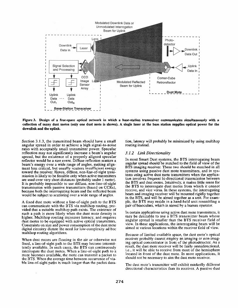
Figure 3 illustrates a free-space optical network utilizing the CCR-based passive uplink. The BTS contains a laser whose beam illuminates an area containing dust motes. This beam can be modulated with downlink data, including commands to wake up and query the dust motes. When the illuminating beam is not modulated, the dust motes can use their CCRs to transmit uplink data back to the base station. A high- frame-rate CCD video camera at the BTS “sees” these CCR signals as lights blinking on and off. It decodes these blink- ing images to yield the uplink data. Kahn and Pister’s analy- sis show that this uplink scheme achieves several kilobits per second over hundreds of meters in full sunlight [6]. At night, in clear, still air, the range should extend to several kilometers. Because the camera uses an imaging process to separate the simultaneous transmissions from dust motes at different locations, we say that it uses space-division multi- plexing. The ability for a video camera to resolve these transmissions is a consequence of the short wavelength of visible or near-infrared light. This does not require any coordination among the dust motes, and thus, it does not complicate their design.
When the application requires dust motes to use active opti- cal transmitters, MEMS technology can be used to assemble a semiconductor laser, a collimating lens and a beam-steer-
f- 200 urn
4 Figure 2. Microfabricated corner-cube retroreflector, consisting of three gold-coated polysilicon mirrors. The base mirror can be deflected electrostatically, modulating the optical signal reflected from the device (taken from [2]).
ing micro-mirror, as shown in Figure 1. Active transmitters make possible peer-to-peer communication between dust motes, provided there exists a line-of-sight path between them. Power consumption imposes a trade-off between bandwidth and range. The dust motes can communication over longer ranges (tens of kilometers) at low data rates or higher bit rates (megabits per second) over shorter dis- tances. The relatively high power consumption of semicon- ductor lasers (of the order of 1 milliwatt) dictates that these active transmitters be used for short-duration burst-mode communication only. Sensor networks using active dust mote transmitters will require some protocol for dust motes to aim their beams toward the receiving parties.
3 Mobile Networking Challenges
3.1 Overview Development of mobile networking protocols for Smart Dust represents a significant challenge. Some critical limita- tions are: (i) the free-space optical links requires uninter- rupted line-of-sight paths, (ii) the passive and active dust mote transmitters have directional characteristics that must be considered in system design, and (iii) there are severe trade-offs between bit rate, energy per bit, distance and directionality in these energy-limited free-space optical links. These limitations are described in more detail in the following subsections.
3.1.1 Line-of-Sight Requirement
An unbroken line-of-sight path is normally required for operation of free-space optical links for Smart Dust. These links cannot operate reliably using non-line-of-sight propa- gation, which would rely on reflections from one or more objects between the transmitter and receiver. As shown in
273
Modulated Downlink Data or
Signal Selection and Processing
Sensor I Beam for Uplink I
Arrav I I
I 1 1
: Up'ink Uplink
Data -a * Data I
out, OUtN I
I Dust Mote I
L---------------J
I Base-Station Transceiver I &.-----------------.I
Figure 3. Design of a free-space optical network in which a base-station transceiver communicates simultaneously with a collection of many dust motes (only one dust mote is shown). A single laser at the base station supplies optical power for the downlink and the uplink.
Section 3.1.3, the transmitted beam should have a small angular spread in order to achieve a high signal-to-noise ratio with acceptably small transmitter power. Specular reflection may not significantly increase a beam’s angular spread, but the existence of a properly aligned specular reflector would be a rare event. Diffuse reflection scatters a beam’s energy over a wide range of angles, making align- ment less critical, but usually scatters insufficient energy toward the receiver. Hence, diffuse, non-line-of-sight trans- mission is likely to be feasible only when active transmitters are used over very short distances (probably under 1 meter). It is probably impossible to use diffuse, non-line-of-sight transmission with passive transmitters (based on CCRs), because both the interrogating beam and the reflected beam would be subject to scattering over a wide range of angles.
A fixed dust mote without a line-of-sight path to the BTS can communicate with the BTS via multihop routing, pro- vided that a suitable multihop path exists. The existence of such a path is more likely when the dust mote density is higher. Multihop routing increases latency, and requires dust motes to be equipped with active optical transmitters. Constraints on size and power consumption of the dust mote digital circuitry dictate the need for low-complexity ad hoc multihop routing algorithms.
When dust motes are floating in the air or otherwise not fixed, a line-of-sight path to the BTS may become intermit- tently available. In such cases, the BTS can continuously interrogate the dust motes. When a line-of-sight path to a mote becomes available, the mote can transmit a packet to the BTS. When the average time between occurrence of via- ble line-of-sight paths is much longer than the packet dura-
tion, latency will probably be minimized by using multihop routing instead.
3.1.2 Link Directionality
In most Smart Dust systems, the BTS interrogating beam angular spread should be matched to the field of view of the BTS imaging receiver. These two should be matched in all systems using passive dust mote transmitters, and in sys- tems using active dust mote transmitters when the applica- tion involves frequent bi-directional transmission between the BTS and dust motes. Intuitively, it makes little sense for the BTS to interrogate dust motes from which it cannot receive, and vice versa. In these systems, the interrogating beam and imaging receiver will be mounted rigidly together in the BTS, and will be aimed together as a unit. For exam- ple, the BTS may reside in a hand-held unit resembling a pair of binoculars, which is aimed by a human operator.
In certain applications using active dust mote transmitters, it may be desirable to use a BTS transmitter beam whose angular spread is smaller than the BTS receiver field of view. In these applications, the interrogating beam will be aimed at various locations within the receiver field of view.
Because of limited available space, the dust mote’s optical receiver probably cannot employ an imaging or non-imag- ing optical concentrator in front of the photodetector. As a result, the dust mote receiver will be fairly omnidirectional, i.e., it will be able to receive from most of the hemisphere located in front of the dust mote. In most applications, it should not be necessary to aim the dust mote receiver.
The dust mote’s transmitter will exhibit markedly different directional characteristics than its receiver. A passive dust
274

mote transmitter is based on the CCR. This device reflects light directly back to the source within a narrow beam’, pro- vided that it is illuminated from a direction that lies within a few tens of degrees of the cube body diagonal. If dust motes use only one CCR each, then any given dust mote, if fixed in a random, upright orientation, has only about a 10% prob- ability of being able to transmit to the BTS. This probability can be increased significantly by equipping each dust mote with several CCRs, each oriented along a different direc- tion. As an alternative, a single CCR may be mounted on a MEMS aiming mechanism. This mechanism need only aim the CCR with an accuracy of the order of 10 or 20 degrees.
Still other solutions exist for coping with the CCR’s direc- tionality. It may be possible to distribute randomly an excess number of dust motes, with the goal of communicat- ing only with those whose CCRs happen to point toward the BTS. If the dust motes are not fixed, it may be best for a dust mote to simply delay transmitting until it moves into an orientation that enables transmission to the BTS.
An active dust mote transmitter is based on a laser diode. It should employ a narrow beamwidth, typically of the order of a few degrees or less (see Section 3.1.3). This necessi- tates equipping the dust mote with an active beam-steering mechanism. Pister and his students are working on a MEMS-based mechanism capable of steering a beam to any position within a hemisphere. Beam-steering algorithms for systems with active dust mote transmitters represent a cur- rent research challenge. It would be desirable for each dust mote to autonomously steer its beam toward the desired direction. One approach would be to make the dust mote receiver directional, and to mount the receiver and transmit- ter on the same aiming mechanism. Accordingly, by aiming its receiver so as to maximize the signal received from the BTS or another mote, the dust mote would be aiming its transmitter at that node. The need for active dust mote trans- mitters to determine the direction to other nodes slows down connection set up, but if nodes remain fixed then the direc- tions of various nodes, once determined, can be stored in the dust mote for future use.
Under most of the scenarios discussed above, the dust mote’s transmitter and receiver have different angular spreads. This leads to non-reciprocal link characteristics, wherein a dust mote may receive from another node, but be unable to transmit to it, or vice versa. As a consequence, a dust mote may receive queries from other nodes, and may attempt to answer them, unaware that its transmissions are in vain. When dust motes are fixed, in order to conserve dust mote power, the other nodes should acknowledge this dust mote’s transmissions, and this dust mote should not answer further queries from nodes that do not acknowledge its transmissions.
It is known that in free-space optical networks, non-reci- procity can lead to “hidden nodes”, which can cause colli- sions during medium access. For example, this effect is observed in networks having a shared-bus physical topol- ogy, and using MAC protocols based on random time-divi- sion multiplexing, such as CSMA-CA with RTS/CTS [4]. In
1. In a well-designed CCR, the angular spread of the reflected beam is limited by diffraction to the order of 0 - h/a, where h is the optical wavelength and a is the effective diameter of the CCR.
Smart Dust networks, the uplink (dust mote to BTS) uses space-division multiplexing. As discussed in Section 2, uplink collisions will not occur as long as the dust motes are sufficiently separated that their transmissions are detected by different pixels in the BTS imaging receiver. Collisions during active peer-to-peer communications are a potential problem in Smart Dust networks. A peer-to-peer collision avoidance scheme must cope with a dynamic network con- figuration, while not introducing excessive complexity or latency.
3.1.3 Trade-Offs Between Bit Rate, Distance and Energy per Bit
Free-space optical links are subject to trade-offs between several design parameters. For simplicity, we consider the case of links employing active laser transmitters. The receiver signal-to-noise ratio (SNR) is given by
2 2 EbRbA SNR = C.- N&k4 *
Here, C is a constant, Eb is the average transmitted energy per Qit, R, is the bit rate, A is the recerver light collection area , N,, is the receiver noise power spectral density, d is the link transmission distance, and Q is the transmitter beam angular spread. This expression assumes that @ is small, and that the transmitter beam is well-aimed at the receiver. The SNR governs the probability of bit error, and must be maintained at a suitably high value to insure reliable link operation. From (l), we see that in order to achieve a given SNR with all other pammAters fixed, the required value of Eh is proportional to R, , i.e., the energy per bit is mini- mized if packets are transmitted in short bursts at a high bit rate.
The average transmitter power (during transmission of a packet) is P, = F,,b/Rb . Hence, transmission at a high bit rate requires a high-power transmitter. In practice, P, should be chosen to be as high as possible, within con- straints posed by eye safety and by dust mote current-drive limitations. Rewriting (1) in terms of P, , we obtain
SNR = C. Pr2A2
N,,Rbdk4 ’
Given a limit on P,, to maximize the bit rate R, and the distance d, we should maximize the receiver area A and minimize 0, i.e., use a highly directional transmitter.
Once all other parameters have been fixed, to maintain a required SNR, th permissible bit rate and distance are related by R, 0~ 2 Hence, it is possible to extend the link distance by drastically lowering the bit rate. If a multihop route is available, overall latency may be minimized by transmitting at a higher bit rate over several hops.
2. On a link from BTS to dust mote or from dust mote to dust mote, A corresponds to the dust mote photodetector area. On a link from dust mote to BTS, A corresDonds to the BTS camera’s entrance aperture area.
275

3.2 Mobile Networking Opportunities
3.2.1 Overview
The optical free-space communication method presents many opportunities beyond low-power, passive communi- cations. Since the application of interest in sensor networks is primarily sensor read-out, the key protocol issues are to perform read-out from a large volume of sensors co-located within a potentially small area. Random access to the medium is both energy-consuming and bandwidth ineffi- cient. So it is extremely useful to exploit passive and broad- cast-oriented techniques when possible. Fortunately the free-space approach supports multiple simultaneous read- out of sensors, mixes active and passive approaches using demand access techniques, and provides efficient and low- latency response to areas of a sensor network that are under- going frequent changes. These are described in more detail in the following subsections, with emphasis on passive dust mote transmitters.
3.2.2 Parallel Read-Out
A single wide beam from the BTS can simultaneously probe many dust motes. The imaging receiver at the BTS receives multiple reflected beams from the motes, as long as they are sufficiently separated in space to be resolved by the receiver’s pixel array. The probe beam sweeps the three dimensional space covered by the base station on a regular basis, most likely determined by the nature of the applica- tion and its need for moment-by-moment sensor readings.
3.2.3 Demand Access
To save transmit power, if the mote must use active commu- nications, then it is best to use the active transmitter in a high-bit-rate, short-burst mode. Familiar demand access methods can be used to combine the low latency advantages of active communications with the low-power advantages of the passive approach.
When the mote needs to transmit information, it actively transmits a short-duration burst signal to the BTS. The BTS, detecting this signal, then probes in the general geographi- cal area from which the burst was detected. Assuming that the passive transmitter (i.e., CCR) is properly oriented toward the BTS, the mote can respond by modulating the reflected probe beam with the data it needs to transmit.
Logically, the communications structure described above has much in common with familiar cellular and satellite net- works [5]. The paging channel is acquired using contention access techniques. The BTS grants a channel to the node requesting attention. In a cellular network, this is accom- plished by assigning a frequency, time slot, and/or code to the node. In the scheme described for dust motes, the chan- nel is “granted” by the incident probe beam.
Note that there are as many channels (paging or data) as there are resolvable pixels at the BTS. The BTS has no way to distinguish between simultaneously communicating dust motes if they fall within the same pixel in the imaging array. One possible way to deal with this is to introduce time slot- ted techniques not unlike that found in time division multi- ple access (TDMA) communications systems. A wide- aperture beam from the BTS could be modulated in such a
fashion as to offer a common time base by which to syn- chronize the motes. The BTS can then signal an individual mote the particular time slot it has assigned to it for commu- nication. The mote must await its time slot to communicate, whether it uses an active or a passive transmitter.
3.2.4 Probe Revisit Rates
Probe beam revisit rates could be determined in an applica- tion-specific manner. It is a well known observation from statistical data management that areas where changes are happening most rapidly should be revisited most frequently, If sensor readings are not changing much, then occasional samples are sufficient to obtain statistically significant results. So it is better to spend probe dwell time on those sensors that are experiencing the most rapid reading changes, and for which infrequent visit would lead to the greatest divergence from the current sensor values.
4 Applications
4.1 Introduction Depending on the application, individual dust motes may be affixed to objects that one wishes to monitor, or a large col- lection of motes may simply be dispersed (and floating!) at random throughout an environment. The motes record sen- sor readings and, when queried, report these readings via the optical techniques described in Section 2. In some applica- tions, dust motes will communicate directly (and passively) with the BTS, In others, peer-to-peer active communication between dust motes will be used to relay information to the BTS. Depending on the application, the base station may be separated from the dust motes by distances ranging from tens of meters to kilometers.
For example, the BTS may actually reside in a hand-held unit, much like a pair of binoculars. This permits the user to simultaneously view a scene while displaying measured data overlaid on top of it. As another example, the BTS may reside in a small flying vehicle, which flies over an area to query the Smart Dust.
We envision numerous civilian and military applications for Smart Dust. Smart Dust may be deployed over a region to record data for meteorological, geophysical or planetary research. It may be employed to perform measurements in environments where wired sensors are unusable or lead to measurement errors. Examples include instrumentation of semiconductor processing chambers, rotating machinery, wind tunnels, and anechoic chambers. In biological research, Smart Dust may be used to monitor the move- ments and internal processes of insects or other small ani- mals. Considering the military arena, Smart Dust may be deployed for stealthy monitoring of a hostile environment, e.g., for verification of treaty compliance. Here, acoustic, vibration or magnetic field sensors could detect the passage of vehicles and other equipment. Smart Dust could be used for perimeter surveillance, or to detect the presence of chemical or biological agents on a battlefield.
The overarching applications challenge, from a processing and communications viewpoint, is how to implement com- plex “ensemble” behavior from a large number of individ- ual, relatively simple sensors. This is sometimes called
276

“beehive”, “swarm”, or “emergent” behavior. A critical enabler is the ability for the sensors to communicate their readings with each other and with the more centralized intelligent processor residing at the base station. Proper design of the network is the key. We describe an applica- tions scenario and some of the technology challenges to implement such a system in this section.
4.2 Scenario: Multi-Sensor Emergent Behavior
It is useful for sensors to operate in ensembles. Rather than implementing a broad range of sensors in a single integrated circuit, it is possible to simply deploy a mixture of different sensors in a given geographical area and allow them to self- organize.
Sensors are typically specialized to detect certain signa- tures. One kind detects motion, another heat, and a third sound. When one sensor detects its critical event signature, it makes other nearby sensors aware of its detection. They then orient their sensing function in a particular, signature- specific way. For example, a simple motion-detecting sen- sor might cue more sophisticated sensors detecting thermal or other radiation properties. The array, acting as an ensem- ble, not only performs the operation of detecting an intruder, but demonstrates more intelligent processing, by distin- guishing between one that is a human and another that is a small animal (e.g., the former has a body heat signature spread over a larger volume than the latter).
A more complex sensor cued in this fashion may then increase its own scan rate to obtain a higher-resolution sig- nature, or dedicate its detection energy budget into a partic- ular narrow band or a specific direction. These operations have implications for power consumption. Maximizing detection probability and resolution while minimizing power consumption is a key optimization challenge.
4.3 Technology Approaches for Realizing the Scenario
There are two ways to construct such a cueing system. The first is a centralized scheme. The motion sensor communi- cates with the BTS, which in turn communicates with a nearby heat sensor. If passive communications techniques can be used, this may well be the most power-efficient way to propagate the detection information.
The centralized/passive schemes cannot be used if the line- of-sight path is blocked, or if the probe revisit rate is too infrequent to meet detection latency constraints. In these cases, the detecting mote must employ an active transmitter. If the line-of-sight path is blocked, then the mote will need to use ad hoc, multihop techniques to communicate with the BTS or nearby sensor nodes.
Detecting a blocked path between a mote and the BTS is not difficult (note that a blocked path and a disabled BTS can be treated in the same way). We can assume some maximum duty cycle between probe visits. If sufficient time has passed since the last visit, the mote can assume that it is blocked. Weighted by the importance of what it has detected, the mote can decide to go active.
Building a multihop route in this environment is quite chal- lenging. Because of the directionality of the on-board laser, active transmission in all directions is not feasible, and we cannot assume that if a next hop node receives our transmis- sion that we will be able to receive a transmission from it.
A possible scheme is the following. A node transmits for a short burst and waits for an ACK response from any Iisten- ing node to determine that its transmission has been received. Determining true reachability between pairs of motes requires a full four phase handshake (“Can you see
7” “Yes, I can see you. Can you see me?’ “Yes” “Good. K’can communicate with each other.“). This must be exe- cuted in the context of appropriate timeouts and made robust to dynamic changes in the positions of the communi- cating nodes, which may be floating in the air.
Routing tables can be constructed from such pairwise dis- covery of connectivity. However, standard routing algo- rithms, like RIP, OSPF, and DVRMP, assume bidirectional and symmetric links. This will not always be the case for Smart Dust. It may be possible for mote A to communicate with mode B, but not vice versa. Even if the communica- tions is bidirectional, it need not exhibit the same bandwidth or loss characteristics in both directions.
Therefore, new routing algorithms must be developed to deal with the general case of links that are unidirectional and/or asymmetric in their performance. A strong group at INRIA in France has been leading the IETF Unidirectional Link Routing Working Group discussions on these issues [31[131.
Unfortunately, the current efforts are focusing on support- ing high-bandwidth unidirectional links where all nodes have at least low-bandwidth bidirectional links (e.g., a high- bandwidth satellite link superimposed on nodes intercon- nected via slow-speed telephone links). Even modifying existing algorithms will not help much, since the connectiv- ity among floating dust motes is dynamic with short time scales. The more general case still remains to be addressed.
4.4 Other Applications Issues One possible improvement is to make use of emerging MEMS technology for on-board inertial navigation circuits [l] to make sensors more aware of near neighbors even as they drift out of line-of-sight of the BTS. The BTS can determine the relative location of dust motes within its field of view. It could then disseminate this “near neighbor infor- mation” to motes able to observe its probe beam. The on- board inertial navigation capability, combined with these periodic relative location “snapshots”, could assist motes in orienting their laser and detector optics to improve their ability to establish links with nearby motes.
5 Related Projects Several projects have recently been initiated to investigate a variety of communications research aspects of distributed sensor networks. The following description is by no means exhaustive.
The Factoid Project [8] at the Compaq Palo Alto Western Research Laboratory (WRL) is developing a portable device
277

small enough to be attached to a key chain. The device col- lects announcements from broadcasting devices in the envi- ronment, and these can be uploaded to a user’s home basestation. In its first generation, the prototype devices are much larger than smart dust motes, communications is accomplished via RF transmission, and the networking depends on short-range point-to-point links.
The Wireless Integrated Network Sensors (WINS) Project [7] at UCLA is very similar in spirit to what has been described in this paper, It is developing low power MEMS- based devices that in addition to sensing and actuating can also communicate. The essential difference is that WINS has chosen to concentrate on RF communications over short distances.
The Ultralow Power Wireless Sensor Project [9] at MIT is another project that focuses on low power sensing devices that also communicate. The primary thrust is extremely low power operation. The prototype system will transmit over a range of data rates, from 1 bitisec to 1 megabitisec, with transmission power levels that span from 10 microwatts to 10 milliwatts. The RF communications subsystem is being developed for the project by Analog Devices. Again, optical technologies are not being investigated. Ultimately the design team will need to face the multi-hop wireless net- working protocol issues outlined in this paper (e.g., see [lo], Hllh
6 Summary and Conclusions
The research community is searching for a new environ- ments in which to generate innovative ideas and prove their effectiveness. A new paradigm beyond desktop computing is capturing the imaginations of systems designs: the so- called “post-PC” era. Wireless sensor networks is one area that promises to yield important applications and demands new approaches to traditional networking problems.
We have described Smart Dust, an integrated approach to networks of millimeter-scale sensing/communicating nodes. Smart Dust can transmit passively using novel optical reflector technology. This provides an inexpensive way to probe a sensor or acknowledge that information was received. Active optical transmission is also possible, but consumes more power. It will be used when passive tech- niques cannot be used, such as when the line-of-sight path between the dust mote and BTS is blocked.
Smart dust provides a very challenging platform in which to investigate applications that can harness the emergent behavior of ensembles of simple nodes. Dealing with partial disconnections while establishing communications via dynamic routing over rapidly changing unidirectional links poses critical research challenges for the mobile networking community.
Acknowledgments
Kahn and Pister’s research is supported in part by DARPA Contract DABT63-98-1-0018, “Smart Dust.” Katz and Pis- ter’s research is supported in part by a new DARPA Con- tract, “Endeavour Expedition to the Information Technology Future.”
7 References
HI
PI
r31
141
VI
161
[71
PI
PI
1101
1111
WI
1131
B. Boser, “Electronics for Micromachined Inertial Sensors,” Transducers’97, Chicago, Il., (June 1997), pp. 1169-1172.
P. B. Chu, N. R. Lo, E. C. Berg, K. S. J. Pister, “Opti- cal Communication Using Micro Corner Cube Reflectors”, Proc. of IEEE MEMS Workshop, Nagoya, Japan, (January 1997), pp. 350-355.
W. Dabbous, E. Duros, T. Ernst, “Dynamic Routing in Networks with Unidirectional Links,” Workshop on Satellite-Based Information Systems, Budapest, (Sep- tember 1997).
F. Gfeller and W. Hirt, “A Robust Wireless Infrared System with Channel Reciprocity”, IEEE Commun. Mag., vol. 36, no. 12, (December 1998), pp. 100-106.
D. Goodman, Wireless Personal Communication Sys- tems, Addison-Wesley Longman, Reading, MA, 1997.
V. S. Hsu, J. M. Kahn, and K. S. J. Pister, “Wireless Communications for Smart Dust”, Electronics Research Laboratory Memorandum Number M98l2, 1998.
http://www.janet.ucla.edu/WINS.
http://www.research.digital.com/wrl/projects/Factoid/ index.html.
http://www-mtl.mit.edu/-jimg/project-top.html.
J. Jubin, J. D. Tumow, “The DARPA Packet Radio Network Protocols,” Proc. IEEE, V. 75, N. 1, (Janu- ary 1987), pp. 21-32.
G S. Lauer, “Packet-Radio Networks,” Chapter 11 in Routing in Communications Networks,” M. Steen- strup, Ed., Englewood Cliffs, N.J., Prentice-Hall, 1995.
N. Stephenson, The Diamond Age, Bantam Books, New York, 1995.
Unidirectional Link Routing Protocol Working Group Home Page, http://www-sop.inria.fr/rodeo/udlr/.
278


![Networking in the 21st Century - [short highlevel virtual view]](https://static.fdocuments.in/doc/165x107/58d1704b1a28abed798b4ad1/networking-in-the-21st-century-short-highlevel-virtual-view.jpg)