Nexcom appc1533 t_controller_at_tains_stability_to_boost_cookie_packing_outcome
Upload
nguyennguyetCategory
view
227download
0
NEXCOM International Co., Ltd.
NEXCOM International Co., Ltd.Published May 2018
www.nexcom.com
IoT Automation Solutions Business GroupIndustrial Panel Display IPPD 1600P/1800P/2100PUser Manual
Copyright © 2015 NEXCOM International Co., Ltd. All Rights Reserved. ii IPPD 1600P/1800P/2100P User Manual
Content
Contents
Preface Copyright ............................................................................................. ivDisclaimer .............................................................................................. ivAcknowledgements ............................................................................... ivRegulatory Compliance Statements ........................................................ ivDeclaration of Conformity ...................................................................... ivRoHS Compliance ................................................................................... vWarranty and RMA ................................................................................ viSafety Information ................................................................................. ixInstallation Recommendations ................................................................ ixSafety Precautions ................................................................................... xTechnical Support and Assistance ........................................................... xiConventions Used in this Manual ........................................................... xiGlobal Service Contact Information ........................................................xiiPackage Contents .................................................................................xivOrdering Information .............................................................................xv
Chapter 1: Product Introduction Overview - IPPD 1600P ............................................................................1Key Features ...........................................................................................1Overview - IPPD 1800P ............................................................................2Key Features ...........................................................................................2Overview - IPPD 2100P ............................................................................3Key Features ...........................................................................................3
Specifications ..........................................................................................4IPPD 1600P ..........................................................................................4
Specifications ..........................................................................................5IPPD 1800P ..........................................................................................5
Specifications ..........................................................................................6IPPD 2100P ..........................................................................................6
Knowing Your IPPD Series .......................................................................7Rear View ............................................................................................7Power & OSD Menu Button Description ...............................................7Rear Bottom View ...............................................................................8External I/O Description .......................................................................8Rear View of IPPD 1600P .....................................................................9Rear View of IPPD 1800P ...................................................................10Rear View of IPPD 2100P ...................................................................11
Mechanical Dimensions .........................................................................12IPPD 1600P ........................................................................................12IPPD 1800P ........................................................................................13IPPD 2100P ........................................................................................14
Chapter 2: Connector Pin Definitions External I/O Interfaces ...........................................................................15
VGA Port ...........................................................................................16DVI Port (DVI-D) .................................................................................16USB Port ............................................................................................17

Copyright © 2015 NEXCOM International Co., Ltd. All Rights Reserved. iii IPPD 1600P/1800P/2100P User Manual
Content
Chapter 3: System SetupPanel Mounting ....................................................................................18
Chapter 4: Adjusting the DisplayOSD Menu Functions ............................................................................20
Appendix A: Extended Display Identification Data Timing Support..............................................33

Copyright © 2015 NEXCOM International Co., Ltd. All Rights Reserved. iv IPPD 1600P/1800P/2100P User Manual
Preface
PrefaCe
Copyright This publication, including all photographs, illustrations and software, is protected under international copyright laws, with all rights reserved. No part of this manual may be reproduced, copied, translated or transmitted in any form or by any means without the prior written consent from NEXCOM International Co., Ltd.
DisclaimerThe information in this document is subject to change without prior notice and does not represent commitment from NEXCOM International Co., Ltd. However, users may update their knowledge of any product in use by constantly checking its manual posted on our website: http://www.nexcom.com. NEXCOM shall not be liable for direct, indirect, special, incidental, or consequential damages arising out of the use of any product, nor for any infringements upon the rights of third parties, which may result from such use. Any implied warranties of merchantability or fitness for any particular purpose is also disclaimed.
AcknowledgementsIPPD 1600P, IPPD 1800P and IPPD 2100P are trademarks of NEXCOM International Co., Ltd. All other product names mentioned herein are registered trademarks of their respective owners.
Regulatory Compliance StatementsThis section provides the FCC compliance statement for Class B devices and describes how to keep the system CE compliant.
Declaration of ConformityFCC
This equipment has been tested and verified to comply with the limits for a Class B digital device, pursuant to Part 15 of FCC Rules. These limits are designed to provide reasonable protection against harmful interference when the equipment is operated in a commercial environment. This equipment generates, uses, and can radiate radio frequency energy and, if not installed and used in accordance with the instructions, may cause harmful interference to radio communications. Operation of this equipment in a residential area (domestic environment) is likely to cause harmful interference, in which case the user will be required to correct the interference (take adequate measures) at their own expense.
CE
The product(s) described in this manual complies with all applicable European Union (CE) directives if it has a CE marking. For computer systems to remain CE compliant, only CE-compliant parts may be used. Maintaining CE compliance also requires proper cable and cabling techniques.

Copyright © 2015 NEXCOM International Co., Ltd. All Rights Reserved. v IPPD 1600P/1800P/2100P User Manual
Preface
RoHS ComplianceNEXCOM RoHS Environmental Policy and Status Update
NEXCOM is a global citizen for building the digital infrastructure. We are committed to providing green products and services, which are compliant with
European Union RoHS (Restriction on Use of Hazardous Substance in Electronic Equipment) directive 2011/65/EU, to be your trusted green partner and to protect our environment.
RoHS restricts the use of Lead (Pb) < 0.1% or 1,000ppm, Mercury (Hg) < 0.1% or 1,000ppm, Cadmium (Cd) < 0.01% or 100ppm, Hexavalent Chromium (Cr6+) < 0.1% or 1,000ppm, Polybrominated biphenyls (PBB) < 0.1% or 1,000ppm, and Polybrominated diphenyl Ethers (PBDE) < 0.1% or 1,000ppm.
In order to meet the RoHS compliant directives, NEXCOM has established an engineering and manufacturing task force to implement the introduction of green products. The task force will ensure that we follow the standard NEXCOM development procedure and that all the new RoHS components and new manufacturing processes maintain the highest industry quality levels for which NEXCOM are renowned.
The model selection criteria will be based on market demand. Vendors and suppliers will ensure that all designed components will be RoHS compliant.
How to recognize NEXCOM RoHS Products?
For existing products where there are non-RoHS and RoHS versions, the suffix “(LF)” will be added to the compliant product name.
All new product models launched after January 2013 will be RoHS compliant. They will use the usual NEXCOM naming convention.

Copyright © 2015 NEXCOM International Co., Ltd. All Rights Reserved. vi IPPD 1600P/1800P/2100P User Manual
Preface
Warranty and RMANEXCOM Warranty Period
1. NEXCOM makes products in accordance with the Industry standard and, NEXCOM warrants that all her Industry-grade IPC and System products will be free from defect in neither material nor workmanship for twenty-four (24) months from the day of invoice issued.
2. For NEXCOM Panel PC product lines (the APPC, MPPC series), they are also guaranteed against defect in materials and workmanship for the period of twenty-four (24) months in their motherboard design. For 3rd party parts, it follows with original suppliers’ standard: 12 months for battery pack and LCD, 24 months for adapter / add on modules (including GSM module, RFID module, and antenna).
3. If NEXCOM determines customer’s warranty claim is valid, NEXCOM will repair or replace product(s) without additional charge for parts and labor. An extended Warranty Program will extend the warranty period of the product accordingly.
Warranty CoverageThe warranty applies only to products manufactured or distributed by NEXCOM and her subsidiaries. This warranty covers all the products/shipments except for:
1. Any claimed defect, products that have been repaired or modified by persons who have not been authorized by NEXCOM or, products which have been subjected to misuse, abuse, accident, improper installation, or usage not in accordance with the product instruction. NEXCOM assumes no liability as a consequence of such events under the term of this warranty.
One example is the replacement of Tablet’s or Hand-held’s LCD display due to scratching stains or other degradation; these will not be covered under this warranty.
2. Damages caused by customers’ delivery/shipping of the product or, product failure resulted from electrical power/voltage shock, or, installation of parts/components which are not supplied/approved by NEXCOM in advance.
3. Third-party products:
a. Software, such as the device drivers,
b. External devices such as HDD, printer, scanner, mouse, LCD panel, battery, and so on,
c. Accessory/parts that were not approved by NEXCOM and,
d. Accessory/parts were added to products after they were shipped from NEXCOM.
Product will be treated as “Out of Warranty “ if:
a. It expires the warranted 24 months period from the day it was purchased.
b. It had been altered by persons other than an authorized NEXCOM service person or, which have been subjected to misuse, abuse, accident, or improper installation.
c. It doesn’t have the original NEXCOM Serial Number labeling for NEXCOM’s warranty period identification or, tracking.

Copyright © 2015 NEXCOM International Co., Ltd. All Rights Reserved. vii IPPD 1600P/1800P/2100P User Manual
Preface
RMA that NEXCOM has determined not to be covered by the warranty will be charged the NEXCOM Standard Repair Fee for the repairing. If a RMA is determined to be not repairable, customer will be notified and product(s) may be returned to customer at their request; a minimum service fee may be charged however.
NEXCOM Return Merchandise Authorization (RMA) ProcedureFor the RMA (Return Merchandise Authorization) shipment, customer is responsible for packaging and shipping the product to the designated NEXCOM service sites, with shipping charges prepaid by the customer. The original NEXCOM shipping box should be used whenever possible. NEXCOM shall pay for the return of the product to the customer’s location. In case of expedited shipping request, an extra service charge shall be assessed and the customer is responsible for this extra return shipping charge.
1. Customers should enclose the “NEXCOM RMA Service Form” with the returned products.
2. Customers need to write down all the information related to the problem on the “ NEXCOM RMA Service Form “ when applying for the RMA service; information will help to understand the problem, including the fault description, on-screen messages, and pictures if possible.
3. Customers could send back the faulty product with or without the accessories and key parts such as the CPU and DIMM. If the key parts are included, please be noted clearly within the return form. NEXCOM takes no responsibility for the parts which are not listed in the return form.
4. Customers hold the responsibility to ensure that the packing of defective products is durable enough to be resistant against further damage due to the transportation; damage caused by transportation is treated as “ Out of Warranty “ under our Warranty specification.
5. RMA product(s) returned by NEXCOM to any location other than the
customer registered delivery address will incur an extra shipping charge, the customer is responsible for paying the extra shipping charges, duties, and taxes of this shipment.
Product Repairing1. NEXCOM will repair defective products covered under this limited
warranty that are returned to NEXCOM; if products do prove to be defective, they will be repaired during their warranty period unless other warranty terms have been specified.
2. NEXCOM owns all parts removed from repaired products.
3. NEXCOM will use parts made by various manufacturers in performing the repair.
4. The repaired products will be warranted subjected to the original warranty coverage and period only.
5. For products returned as defective but, proved to be no defect/fault after the RMA process, NEXCOM reserves the right to claim for a NDF (No Defect Found) Service Charge.
6. NEXCOM will issue RMA Report which included Repair Detailed Information to the customer when the defective products were repaired and returned.
7. In addition to the above, NEXCOM may authorize Independent/Third- party suppliers to repair the defective products for NEXCOM.
Copyright © 2015 NEXCOM International Co., Ltd. All Rights Reserved. viii IPPD 1600P/1800P/2100P User Manual
Preface
Out Of Warranty ServiceThere will be a service charge from NEXCOM for the “Out Of Warranty” product service; they are the Basic Diagnostic Service Fee and the Advanced Component Replacement Fee respectively. And, if the product can not be repaired, NEXCOM will either return the product to the customer or, just scrap it, followed by customer’s instruction.
1. Testing and Parts Replacement
NEXCOM will have the following Handling Charges for those OoW products that returned:
a. Basic Labor Cost and Testing Fee: as Table listed.
b. Parts Fee: NEXCOM will charge for main IC chipsets such as the N.B., S.B., Super-IO, LAN, Sound, Memory, and so on.
c. 3rd-party Device Fee: products replacement for CPU, DIMM, HDD, Chassis, and UPS.
2. Out of Warranty product will have a three months warranty for the fixed issues. If the product failed with different problem within 3 months, they will still incur the service charge of “Out of Warranty”.
3. Out of Warranty “products will not be repaired without a signed PI from the customer, the agreement of the repair process.
Add-on card, 3rd Party Device and board level repair cost higher than new product prices, customer can abandon to sign PI to repair and, please contact with sales to buy new products.

Copyright © 2015 NEXCOM International Co., Ltd. All Rights Reserved. ix IPPD 1600P/1800P/2100P User Manual
Preface
Installation RecommendationsEnsure you have a stable, clean working environment. Dust and dirt can get into components and cause a malfunction. Use containers to keep small components separated.
Adequate lighting and proper tools can prevent you from accidentally damaging the internal components. Most of the procedures that follow require only a few simple tools, including the following:
▪ A Philips screwdriver
▪ A flat-tipped screwdriver
▪ A grounding strap
▪ An anti-static pad
Using your fingers can disconnect most of the connections. It is recommended that you do not use needle-nose pliers to disconnect connections as these can damage the soft metal or plastic parts of the connectors.
Safety InformationBefore installing and using the device, note the following precautions:
▪ Read all instructions carefully.
▪ Do not place the unit on an unstable surface, cart, or stand.
▪ Follow all warnings and cautions in this manual.
▪ When replacing parts, ensure that your service technician uses parts specified by the manufacturer.
▪ Avoid using the system near water, in direct sunlight, or near a heating device.
▪ The load of the system unit does not solely rely for support from the rackmounts located on the sides. Firm support from the bottom is highly necessary in order to provide balance stability.

Copyright © 2015 NEXCOM International Co., Ltd. All Rights Reserved. x IPPD 1600P/1800P/2100P User Manual
Preface
Safety Precautions1. Read these safety instructions carefully.
2. Keep this User Manual for later reference.
3. Disconnect this equipment from any AC outlet before cleaning. Use a damp cloth. Do not use liquid or spray detergents for cleaning.
4. For plug-in equipment, the power outlet socket must be located near the equipment and must be easily accessible.
5. Keep this equipment away from humidity.
6. Put this equipment on a stable surface during installation. Dropping it or letting it fall may cause damage.
7. The openings on the enclosure are for air convection to protect the equipment from overheating. DO NOT COVER THE OPENINGS.
8. Make sure the voltage of the power source is correct before connecting the equipment to the power outlet.
9. Place the power cord in a way so that people will not step on it. Do not place anything on top of the power cord. Use a power cord that has been approved for use with the product and that it matches the voltage and current marked on the product’s electrical range label. The voltage and current rating of the cord must be greater than the voltage and current rating marked on the product.
10. All cautions and warnings on the equipment should be noted.
11. If the equipment is not used for a long time, disconnect it from the power source to avoid damage by transient overvoltage.
12. Never pour any liquid into an opening. This may cause fire or electrical shock.
13. Never open the equipment. For safety reasons, the equipment should be opened only by qualified service personnel.
14. If one of the following situations arises, get the equipment checked by service personnel: a. The power cord or plug is damaged. b. Liquid has penetrated into the equipment. c. The equipment has been exposed to moisture. d. The equipment does not work well, or you cannot get it to work
according to the user’s manual. e. The equipment has been dropped and damaged. f. The equipment has obvious signs of breakage.
15. Do not place heavy objects on the equipment.
16. The unit uses a three-wire ground cable which is equipped with a third pin to ground the unit and prevent electric shock. Do not defeat the purpose of this pin. If your outlet does not support this kind of plug, contact your electrician to replace your obsolete outlet.
17. CAUTION: DANGER OF EXPLOSION IF BATTERY IS INCORRECTLY REPLACED. REPLACE ONLY WITH THE SAME OR EQUIVALENT TYPE RECOMMENDED BY THE MANUFACTURER. DISCARD USED BATTERIES ACCORDING TO THE MANUFACTURER’S INSTRUCTIONS.
Copyright © 2015 NEXCOM International Co., Ltd. All Rights Reserved. xi IPPD 1600P/1800P/2100P User Manual
Preface
Technical Support and Assistance1. For the most updated information of NEXCOM products, visit NEXCOM’s
website at www.nexcom.com.
2. For technical issues that require contacting our technical support team or sales representative, please have the following information ready before calling: – Product name and serial number – Detailed information of the peripheral devices – Detailed information of the installed software (operating system,
version, application software, etc.) – A complete description of the problem – The exact wordings of the error messages
Warning! 1. Handling the unit: carry the unit with both hands and handle it with care.
2. Maintenance: to keep the unit clean, use only approved cleaning products or clean with a dry cloth.
Conventions Used in this Manual
Warning: Information about certain situations, which if not observed, can cause personal injury. This will prevent injury to yourself when performing a task.
CAUTION!CAUTION!CAUTION! Caution: Information to avoid damaging components or losing data.
Note: Provides additional information to complete a task easily.
Copyright © 2015 NEXCOM International Co., Ltd. All Rights Reserved. xii IPPD 1600P/1800P/2100P User Manual
Preface
Global Service Contact InformationHeadquartersNEXCOM International Co., Ltd.9F, No. 920, Chung-Cheng Rd., ZhongHe District, New Taipei City, 23586, Taiwan, R.O.C.Tel: +886-2-8226-7786 Fax: +886-2-8226-7782 www.nexcom.com
AmericaUSANEXCOM USA2883 Bayview Drive, Fremont CA 94538, USA Tel: +1-510-656-2248 Fax: +1-510-656-2158Email: [email protected]
AsiaTaiwanNEXCOM Intelligent SystemsTaipei Office13F, No.920, Chung-Cheng Rd.,ZhongHe District,New Taipei City, 23586, Taiwan, R.O.C.Tel: +886-2-8226-7796Fax: +886-2-8226-7792Email: [email protected]
NEXCOM Intelligent SystemsTaichung Office16F, No.250, Sec. 2, Chongde Rd., Beitun Dist., Taichung City 406, R.O.C. Tel: +886-4-2249-1179Fax: +886-4-2249-1172Email: [email protected]
JapanNEXCOM Japan9F, Tamachi Hara Bldg., 4-11-5, Shiba Minato-ku, Tokyo, 108-0014, Japan Tel: +81-3-5419-7830Fax: +81-3-5419-7832Email: [email protected]
ChinaNEXCOM ChinaFloor 5, No.4, No.7 fengxian middle Rd.,(Beike Industrial Park), Haidian District,Beijing, 100094, ChinaTel: +86-10-5704-2680Fax: +86-10-5704-2681Email: [email protected] www.nexcom.cn

Copyright © 2015 NEXCOM International Co., Ltd. All Rights Reserved. xiii IPPD 1600P/1800P/2100P User Manual
Preface
EuropeUnited KingdomNEXCOM EUROPE10 Vincent Avenue, Crownhill Business Centre,Milton Keynes, BuckinghamshireMK8 0AB, United Kingdom Tel: +44-1908-267121Fax: +44-1908-262042Email: [email protected]
ItalyNEXCOM ITALIA S.r.lVia Lanino 42, 21047 Saronno (VA), ItaliaTel: +39 02 9628 0333Fax: +39 02 9625 570Email: [email protected]
NEXCOM ShanghaiRoom 603/604, Huiyinmingzun Plaza Bldg., 1, No.609, Yunlin East Rd., Shanghai, 200333, ChinaTel: +86-21-5278-5868Fax: +86-21-3251-6358Email: [email protected] www.nexcom.cn
NEXCOM Surveillance Technology Corp.Room202, Building B,the GuangMing Industrial Zone Zhonghua Rd.,Minzhi Street, Longhua District,Shenzhen 518131, ChinaTel: +86-755-8364-7768 Fax: +86-755-8364-7738Email: [email protected] www.nexcom.cn
NEXCOM United System ServiceHui Yin Ming Zun Building Room 1108, Building No. 11, 599 Yunling Road, Putuo District, Shanghai, 200062, ChinaTel: +86-21-6125-8282Fax: +86-21-6125-8281Email: [email protected]

Copyright © 2015 NEXCOM International Co., Ltd. All Rights Reserved. xiv IPPD 1600P/1800P/2100P User Manual
Preface
Package ContentsBefore continuing, verify that the package you received is complete. The IPPD series package, IPPD 1600P/1800P/2100P, should have all the items listed in the table.
Note: Package contents may vary depending on your country region, some items may be optional. Please contact your local distributor for more information.
Item Description Qty1 USB Touch Cable (1.8m) 12 VGA Cable (1.8m) 13 Terminal blocks 3-pin Phoenix Contact Plug 1
Terminal blocks 3-pin Phoenix Contact Plug
VGA CableUSB Touch Cable

Copyright © 2015 NEXCOM International Co., Ltd. All Rights Reserved. xv IPPD 1600P/1800P/2100P User Manual
Preface
Ordering InformationThe following provides ordering information for the Industrial Panel Display series.
• Barebone
IPPD 1600P-B (P/N: 10IZ1600P01X0)15.6” WXGA heavy industrial 16:9 LED backlight P-Cap touch monitorwith VGA, DVI-D and DisplayPort input, 12~24VDC input
IPPD 1800P-B (P/N: 10IZ1800P01X0)18.5” WXGA heavy industrial 16:9 LED backlight P-Cap touch monitorwith VGA, DVI-D and DisplayPort input, 12~24VDC input
IPPD 2100P-B (P/N: 10IZ2100P01X0)21.5” Full HD heavy industrial 16:9 LED backlight P-Cap touch monitorwith VGA, DVI-D and DisplayPort input, 12~24VDC input US Power Cord (P/N: 60233POW17X00)
Power Adapter (P/N: 7400060019X00) DIN Rail Power Supply (P/N: 7440060001X00)
UK Power Cord (P/N: 60233POW19X00)
EU Power Cord (P/N: 60233POW18X00) 1.8m DVI-D Cable (P/N: 60233DVI28X00)
Optional• 12V, 60W AC/DC power adapter w/o power cord
(P/N: 7400060031X00)• 1.8m DVI-D male to DVI-D male cable (P/N: 603DVI0007X00)• 1.8m DisplayPort cable (P/N: 6030000122X00)

Copyright © 2015 NEXCOM International Co., Ltd. All Rights Reserved. 1
Chapter 1: Product Introduction
IPPD 1600P/1800P/2100P User Manual
ChaPter 1: ProduCt IntroduCtIon
Key Features ▪ IP66 compliant and metal housing with robust aluminum front zero bezel
for harsh environment
▪ 10 points P-Cap multi-touch with zero bezel flush front design
▪ 3 display input interfaces: Analog VGA/DVI-D/DisplayPort
▪ Shares identical appearance with IPPC series
▪ Ultra slim in depth
▪ OSD multi-language function
▪ All connectors with lock
▪ Mounting support: panel/wall/stand/VESA 100mm x 100mm
▪ Wide range power input 12V~24V DC
Overview - IPPD 1600P
Photo is for reference. Please refer to the mechanical engineering drawing for final
appearance.
Note:

Copyright © 2015 NEXCOM International Co., Ltd. All Rights Reserved. 2
Chapter 1: Product Introduction
IPPD 1600P/1800P/2100P User Manual
Key Features ▪ IP66 compliant and metal housing with robust aluminum front zero bezel
for harsh environment
▪ 10 points P-Cap multi-touch with zero bezel flush front design
▪ 3 display input interfaces: Analog VGA/DVI-D/DisplayPort
▪ Shares identical appearance with IPPC series
▪ Ultra slim in depth
▪ OSD multi-language function
▪ All connectors with lock
▪ Mounting support: panel/wall/stand/VESA 100mm x 100mm
▪ Wide range power input 12V~24V DC
Overview - IPPD 1800P
Photo is for reference. Please refer to the mechanical engineering drawing for final
appearance.
Note:

Copyright © 2015 NEXCOM International Co., Ltd. All Rights Reserved. 3
Chapter 1: Product Introduction
IPPD 1600P/1800P/2100P User Manual
Key Features ▪ IP66 compliant and metal housing with robust aluminum front zero bezel
for harsh environment
▪ 10 points P-Cap multi-touch with zero bezel flush front design
▪ 3 display input interfaces: Analog VGA/DVI-D/DisplayPort
▪ Shares identical appearance with IPPC series
▪ Ultra slim in depth
▪ OSD multi-language function
▪ All connectors with lock
▪ Mounting support: panel/wall/stand/VESA 100mm x 100mm
▪ Wide range power input 12V~24V DC
Overview - IPPD 2100P
Photo is for reference. Please refer to the mechanical engineering drawing for final
appearance.
Note:

Copyright © 2015 NEXCOM International Co., Ltd. All Rights Reserved. 4
Chapter 1: Product Introduction
IPPD 1600P/1800P/2100P User Manual
SpecificationsIPPD 1600PPanel ▪ LED size: 15.6”, 16:9 ▪ Resolution: WXGA 1366 x 768 ▪ Luminance: 400cd/m2
▪ Contrast ratio: 500 ▪ LCD color: 16.7M ▪ Viewing angle: 80 (U), 80 (D), 85 (L), 85 (R) ▪ Backlight: LED
Touch Screen ▪ Ten points P-Cap (projected capacitive touch) ▪ Touch light transmission: 87% ▪ Anti-scratch surface: 7H hardness ▪ Touch interface: USB
Rear I/O ▪ Touch interface port: USB with Lock ▪ Video port: VGA (1 x DB15)/DVI-D (1 x DVI-D connector)/DisplayPort ▪ DC power input connector: 3-pin PHOENIX CONTACT terminal block
OSD Function
▪ OSD keypad ▪ Multilanguage OSD
Mechanical & Environment
▪ Color: Pantone 432C/RAL 70 24 front bezel ▪ IP protection: IP66 front ▪ Mounting: panel/wall/stand/VESA 100mm x 100mm ▪ System with panel mounting kit w/o panel mounting hole ▪ Power input: 12V~24VDC ▪ Power adapter: optional AC to DC power adapter (+12V, 60W) ▪ Vibration:
- IEC 68 2-64 - 2Grms @ sine, 5~500Hz, 1hr/axis (operating) - 2.2Grms @ random condition, 5~500Hz, 0.5hr/axis (non-operating)
▪ Shock: - IEC 68 2-27 - HDD: 20G@wall mount, half sine, 11ms
▪ Operating temperature: -10°C to 60°C ▪ Storage temperature: -20°C to 75°C ▪ Operating humidity: 10%~90% relative humidity, non-condensing ▪ Dimension: 417.4 x 312.4 x 51.75mm ▪ Weight: 5.48kg
Certifications
▪ CE (including EN61000-6-1/EN61000-6-2/EN61000-6-3/EN61000-6-4) ▪ FCC Class B

Copyright © 2015 NEXCOM International Co., Ltd. All Rights Reserved. 5
Chapter 1: Product Introduction
IPPD 1600P/1800P/2100P User Manual
SpecificationsIPPD 1800PPanel ▪ LED size: 18.5”, 16:9 ▪ Resolution: WXGA 1366 x 768 ▪ Luminance: 400cd/m2
▪ Contrast ratio: 1000 ▪ LCD color: 16.7M ▪ Viewing angle: 80 (U), 80 (D), 85 (L), 85 (R) ▪ Backlight: LED
Touch Screen ▪ Ten points P-Cap (projected capacitive touch) ▪ Touch light transmission: 87% ▪ Anti-scratch surface: 7H hardness ▪ Touch interface: USB ▪ Windows 8 compliance
Rear I/O ▪ Touch interface port: USB with Lock ▪ Video port: VGA (1 x DB15)/DVI-D (1 x DVI-D connector)/DisplayPort ▪ DC power input connector: 3-pin PHOENIX CONTACT terminal block
OSD Function
▪ OSD keypad ▪ Multilanguage OSD
Mechanical & Environment
▪ Color: Pantone 432C/RAL 70 24 front bezel ▪ IP protection: IP66 front ▪ Mounting: panel/wall/stand/VESA 100mm x 100mm ▪ System with panel mounting kit w/o panel mounting hole ▪ Power input: 12V~24VDC ▪ Power adapter: optional AC to DC power adapter (+12V, 60W) ▪ Vibration:
- IEC 68 2-64 - 2Grms @ sine, 5~500Hz, 1hr/axis (operating) - 2.2Grms @ random condition, 5~500Hz, 0.5hr/axis (non-operating)
▪ Shock: - IEC 68 2-27 - HDD: 20G@wall mount, half sine, 11ms
▪ Operating temperature: -10°C to 60°C ▪ Storage temperature: -20°C to 75°C ▪ Operating humidity: 10%~90% relative humidity, non-condensing ▪ Dimension: 490.8 x 320.6 x 50.65mm ▪ Weight: 6.24kg
Certifications
▪ CE (including EN61000-6-1/EN61000-6-2/EN61000-6-3/EN61000-6-4) ▪ FCC Class B
Copyright © 2015 NEXCOM International Co., Ltd. All Rights Reserved. 6
Chapter 1: Product Introduction
IPPD 1600P/1800P/2100P User Manual
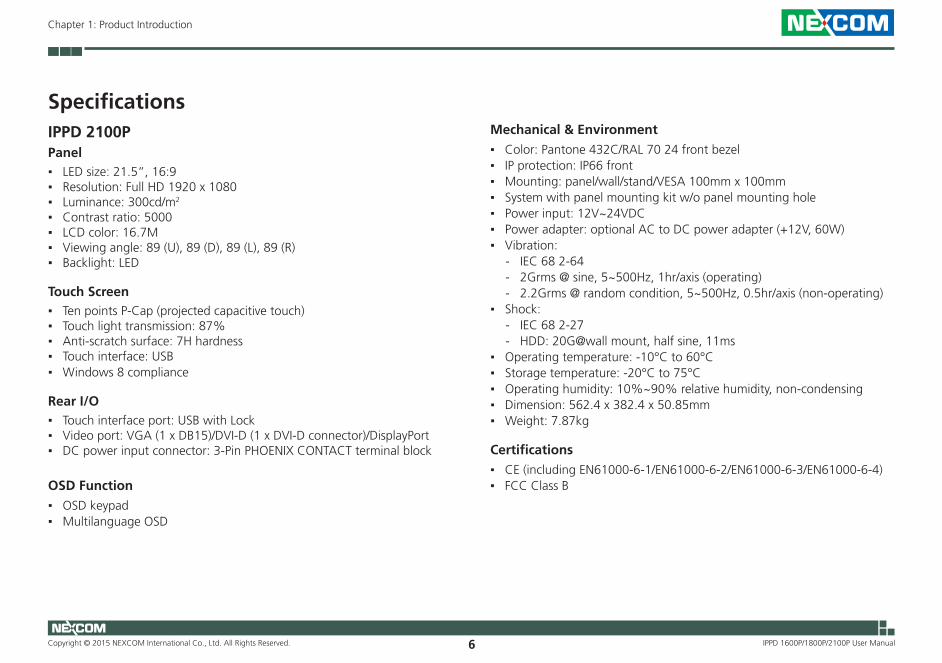
SpecificationsIPPD 2100PPanel ▪ LED size: 21.5”, 16:9 ▪ Resolution: Full HD 1920 x 1080 ▪ Luminance: 300cd/m2
▪ Contrast ratio: 5000 ▪ LCD color: 16.7M ▪ Viewing angle: 89 (U), 89 (D), 89 (L), 89 (R) ▪ Backlight: LED
Touch Screen ▪ Ten points P-Cap (projected capacitive touch) ▪ Touch light transmission: 87% ▪ Anti-scratch surface: 7H hardness ▪ Touch interface: USB ▪ Windows 8 compliance
Rear I/O ▪ Touch interface port: USB with Lock ▪ Video port: VGA (1 x DB15)/DVI-D (1 x DVI-D connector)/DisplayPort ▪ DC power input connector: 3-Pin PHOENIX CONTACT terminal block
OSD Function
▪ OSD keypad ▪ Multilanguage OSD
Mechanical & Environment
▪ Color: Pantone 432C/RAL 70 24 front bezel ▪ IP protection: IP66 front ▪ Mounting: panel/wall/stand/VESA 100mm x 100mm ▪ System with panel mounting kit w/o panel mounting hole ▪ Power input: 12V~24VDC ▪ Power adapter: optional AC to DC power adapter (+12V, 60W) ▪ Vibration:
- IEC 68 2-64 - 2Grms @ sine, 5~500Hz, 1hr/axis (operating) - 2.2Grms @ random condition, 5~500Hz, 0.5hr/axis (non-operating)
▪ Shock: - IEC 68 2-27 - HDD: 20G@wall mount, half sine, 11ms
▪ Operating temperature: -10°C to 60°C ▪ Storage temperature: -20°C to 75°C ▪ Operating humidity: 10%~90% relative humidity, non-condensing ▪ Dimension: 562.4 x 382.4 x 50.85mm ▪ Weight: 7.87kg
Certifications
▪ CE (including EN61000-6-1/EN61000-6-2/EN61000-6-3/EN61000-6-4) ▪ FCC Class B

Copyright © 2015 NEXCOM International Co., Ltd. All Rights Reserved. 7
Chapter 1: Product Introduction
IPPD 1600P/1800P/2100P User Manual
Knowing Your IPPD SeriesRear View
Power & OSD Menu Buttons
Power & OSD Menu Button Description
LED
Power Switch
Increase Brightness/ move down/
increase value Menu
Decrease Brightness/ move up/
decrease value
AUTO|EXIT
LED
Displays the power status of the display. Green LED indicates the display is switched on, if the display is not connected to a computer, the LED will flash red.
Power Switch
Press to power-on or power-off the display.
◀|▼Inside OSD menu: Press to move the selection down in OSD menu.Configuring options: Press to increase the value.
▶|▲Inside OSD menu: Press to move the selection up in OSD menu.Configuring options: Press to decrease the value
OSD Menu
No OSD Menu: Press to load the OSD menu.Inside OSD Menu: Press to select the highlighted option in OSD menu.
AUTO|EXIT
Press to exit the OSD menu, or return to main menu.
Copyright © 2015 NEXCOM International Co., Ltd. All Rights Reserved. 8
Chapter 1: Product Introduction
IPPD 1600P/1800P/2100P User Manual
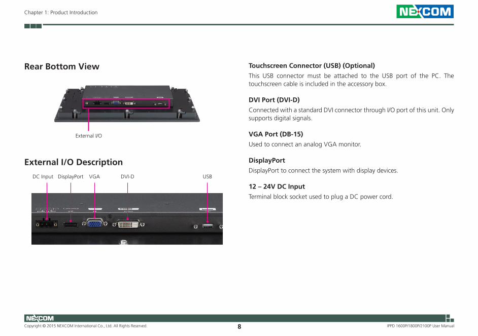
Rear Bottom View
External I/O Description
USBVGADisplayPort DVI-DDC Input
Touchscreen Connector (USB) (Optional)
This USB connector must be attached to the USB port of the PC. The touchscreen cable is included in the accessory box.
DVI Port (DVI-D)
Connected with a standard DVI connector through I/O port of this unit. Only supports digital signals.
VGA Port (DB-15)
Used to connect an analog VGA monitor.
DisplayPort
DisplayPort to connect the system with display devices.
12 – 24V DC Input
Terminal block socket used to plug a DC power cord.
External I/O
Copyright © 2015 NEXCOM International Co., Ltd. All Rights Reserved. 9
Chapter 1: Product Introduction
IPPD 1600P/1800P/2100P User Manual
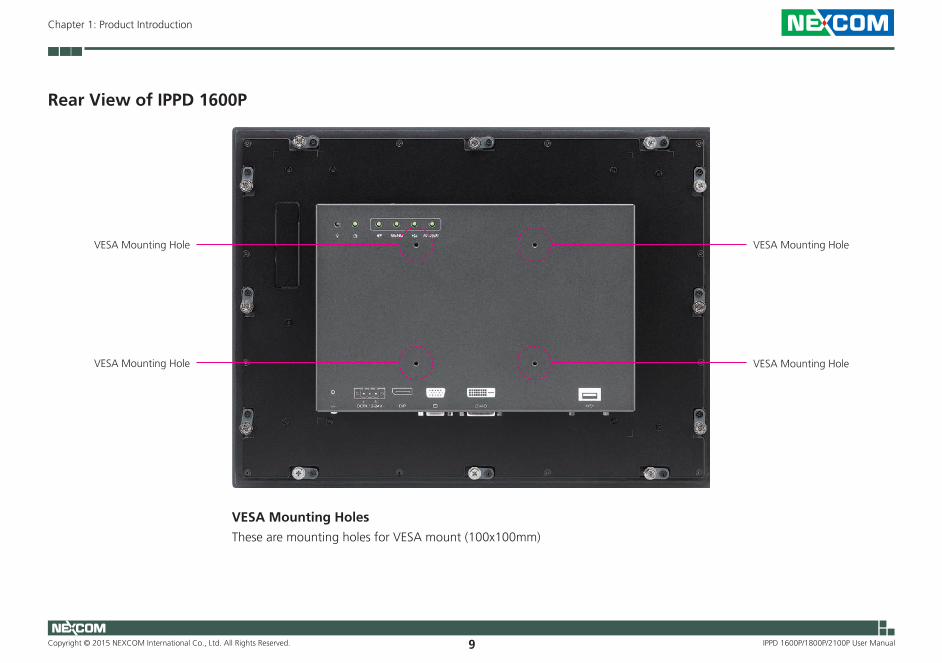
Rear View of IPPD 1600P
VESA Mounting Hole
VESA Mounting Hole
VESA Mounting Hole
VESA Mounting Hole
VESA Mounting Holes
These are mounting holes for VESA mount (100x100mm)

Copyright © 2015 NEXCOM International Co., Ltd. All Rights Reserved. 10
Chapter 1: Product Introduction
IPPD 1600P/1800P/2100P User Manual
Rear View of IPPD 1800P
VESA Mounting Hole
VESA Mounting Hole
VESA Mounting Hole
VESA Mounting Hole
VESA Mounting Holes
These are mounting holes for VESA mount (100x100mm)

Copyright © 2015 NEXCOM International Co., Ltd. All Rights Reserved. 11
Chapter 1: Product Introduction
IPPD 1600P/1800P/2100P User Manual
Rear View of IPPD 2100P
VESA Mounting Hole
VESA Mounting Hole
VESA Mounting Hole
VESA Mounting Hole
VESA Mounting Holes
These are mounting holes for VESA mount (100x100mm)

Copyright © 2015 NEXCOM International Co., Ltd. All Rights Reserved. 12
Chapter 1: Product Introduction
IPPD 1600P/1800P/2100P User Manual
Mechanical Dimensions
270
417.4 (OUTLINE)
345.89 (V/A)35.76
75.7
59.4
195.
17 (
V/A
)
312.
4 (O
UTL
INE)
Active Area (344.23*193.54)
Active Center
6.2
51.75
67.7
176
26.75
291
(MO
UN
TIN
G L
INE)
40.4
10.9
103.
510
3.5
55
396 (MOUNTING LINE)
60.5 150 167.5 46
10.9
102.
710
0
156.7100
398±1
293±
1
CUT OUT SIZE T=12mm (MAX)
12
IPPD 1600P

Copyright © 2015 NEXCOM International Co., Ltd. All Rights Reserved. 13
Chapter 1: Product Introduction
IPPD 1600P/1800P/2100P User Manual
270 112.4
490.8 (OUTLINE)
411.6 (V/A)39.6
44.2
232.
2 (V
/A)
320.
6 (O
UTL
INE)
Active Area (344.23*193.54)
Active Center
6.5
50.65
59.2
176
25.65
300.
2 (M
OU
NTI
NG
LIN
E)
470.4 (MOUNTING LINE)
167.5 167.5 65.4
10.2
10.2
55.9
91.9
94.2
100
100
472.4±1
302.
2±1
CUT OUT SIZE T=12mm (MAX)
2 12
193.4
91.9
IPPD 1800P

Copyright © 2015 NEXCOM International Co., Ltd. All Rights Reserved. 14
Chapter 1: Product Introduction
IPPD 1600P/1800P/2100P User Manual
270 148
562.4 (OUTLINE)478.64 (V/A)41.88
56.1
427
0.11
(V/A
)38
2.4
(OU
TLIN
E)
Active Area (476.64*268.11)
Active Center
50.85
6.7
70.7
176
25.85
362
(MO
UN
TIN
G L
INE)
10.2
75.2
103.
510
3.5
542 (MOUNTING LINE)
167.5 167.5 101.2
10.2
105.
710
0
100
544±1
364±
1
229.45
12
CUT OUT SIZE T=12mm (MAX)
IPPD 2100P

Copyright © 2015 NEXCOM International Co., Ltd. All Rights Reserved. 15
Chapter 2: Connector Pin Definitions
IPPD 1600P/1800P/2100P User Manual
ChaPter 2: ConneCtor PIn defInItIons
External I/O Interfaces12V-24V DC Power InputConnector type: Phoenix Contact 1x3 3-pin terminal block
31
+
Pin Definition1 +2 -3 GND
DisplayPortConnector type: DisplayPort
Pin Definition Pin Definition1 LANE0_P 2 GND3 LANE0_N 4 LANE1_P5 GND 6 LANE1_N7 LANE2_P 8 GND9 LANE2_N 10 LANE3_P
11 GND 12 LANE3_N13 CONFIG1 14 CONFIG215 AUX_CH_P 16 GND17 AUX_CH_N 18 HPD19 RETURN 20 DP_PWR
2119
20

Copyright © 2015 NEXCOM International Co., Ltd. All Rights Reserved. 16
Chapter 2: Connector Pin Definitions
IPPD 1600P/1800P/2100P User Manual
VGA PortConnector type: DB-15 port, 15-pin D-Sub
Pin Definition Pin Definition1 RED 2 GREEN3 BLUE 4 ID25 GND 6 RGND7 GGND 8 BGND9 KEY 10 SGND11 ID0 12 SDA13 HSYNC or CSYNC 14 VSYNC15 SCL
5 1
15 11
1
1115
5
DVI Port (DVI-D)Connector type: 24-pin D-Sub, 2.0mm-M-180 (DVI)
Pin Definition Pin Definition1 TMDS Data 2- 2 TMDS Data 2+3 Shield 4 NC5 NC 6 DDC clock7 DDC data 8 Reserved9 TMDS Data 1- 10 TMDS Data 1+11 Shield 12 NC13 NC 14 +5V15 GND 16 Hot plug detect17 TMDS data 0- 18 TMDS data 0+19 Shield 20 NC21 NC 22 Shield23 TMDS clock+ 24 TMDS clock-C1 NC C2 NCC3 NC C4 NCC5 NC
1 8
17 24

Copyright © 2015 NEXCOM International Co., Ltd. All Rights Reserved. 17
Chapter 2: Connector Pin Definitions
IPPD 1600P/1800P/2100P User Manual
Pin Definition1 VCC52 DATA_N3 DATA_P4 GND
41
USB PortConnector type: USB port

Copyright © 2015 NEXCOM International Co., Ltd. All Rights Reserved. 18
Chapter 3: System Setup
IPPD 1600P/1800P/2100P User Manual
ChaPter 3: system setuP
Panel Mounting1. Select a place on the panel where you will mount the Industrial Touch
Monitor.
2. Cut out a shape on the panel that corresponds to the Industrial Touch Monitor’s rear dimensions.
The thickness of the panel (e.g. steel board, plank, acrylic board, wall, etc.) where you will mount the Industrial Touch Monitor must not exceed 12mm. If the distance between the front bezel and panel mount hole is too wide, it will not fit the panel mount kit.
IPPD 1600P IPPD 2100P
IPPD 1800P
398±1 544±1
472.4±1 12mm
302.
2±1
364±
1
12mm
293±
1
12mm

Copyright © 2015 NEXCOM International Co., Ltd. All Rights Reserved. 19
Chapter 3: System Setup
IPPD 1600P/1800P/2100P User Manual
CAUTION!CAUTION!CAUTION! Do not overtighten the screws to prevent damaging the Panel PC.
3. Slide the Industrial Touch Monitor through the hole until it is properly fitted against the panel.
4. Position the mounting clamps along the rear edges of the Industrial Touch Monitor. The first and second clamps must be positioned and secured diagonally prior to mounting the rest of the clamps. Tighten the clamp’s screw until it touches the panel.

Copyright © 2015 NEXCOM International Co., Ltd. All Rights Reserved. 20
Chapter 4: Adjusting the Display
IPPD 1600P/1800P/2100P User Manual
ChaPter 4: adjustIng the dIsPlay
OSD Menu FunctionsThe On Screen Display (OSD) menu provides options to adjust the display. Press the MENU button on the back of the display panel to open the OSD menu. Refer to the images below for each OSD menu option.
1. Luminance
OSD
Contrast
Brightness
Eco Mode
DCR
Luminance
Standard
O�
90
50
OSD
Luminance
Standard
O�
90
50Contrast
Brightness
Eco Mode
DCR
Contrast
► luminance ► ► contrast ► ► to increase the contrast.
► luminance ► ► contrast ► ► to decrease the contrast.

Copyright © 2015 NEXCOM International Co., Ltd. All Rights Reserved. 21
Chapter 4: Adjusting the Display
IPPD 1600P/1800P/2100P User Manual
Brightness
► luminance ► ► ► Brightness ► ► to increase the
brightness.
► luminance ► ► ► Brightness ► ► to decrease the
brightness.
OSD
Luminance
Standard
O�
90
50Contrast
Brightness
Eco Mode
DCR OSD
Luminance
◄ Standard ►
O�
90
50Contrast
Brightness
Eco Mode
DCR
Eco Mode
► luminance ► ► ► Eco Mode ► ► ► to scroll left to
change between the Eco Mode settings.
► luminance ► ► ► Eco Mode ► ► ► to scroll right to
change between the Eco Mode settings.
The following Eco Mode options are available: Text, Standard, Sports, Movie, Game and Internet.
Copyright © 2015 NEXCOM International Co., Ltd. All Rights Reserved. 22
Chapter 4: Adjusting the Display
IPPD 1600P/1800P/2100P User Manual
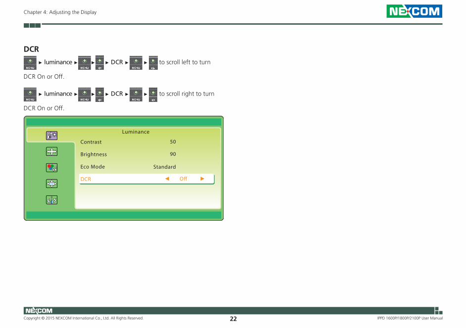
DCR
► luminance ► ► ► DCR ► ► to scroll left to turn
DCR On or Off.
► luminance ► ► ► DCR ► ► to scroll right to turn
DCR On or Off.
OSD
Luminance
◄ O� ►
90
50Contrast
Brightness
Eco Mode
DCR
Standard
Copyright © 2015 NEXCOM International Co., Ltd. All Rights Reserved. 23
Chapter 4: Adjusting the Display
IPPD 1600P/1800P/2100P User Manual
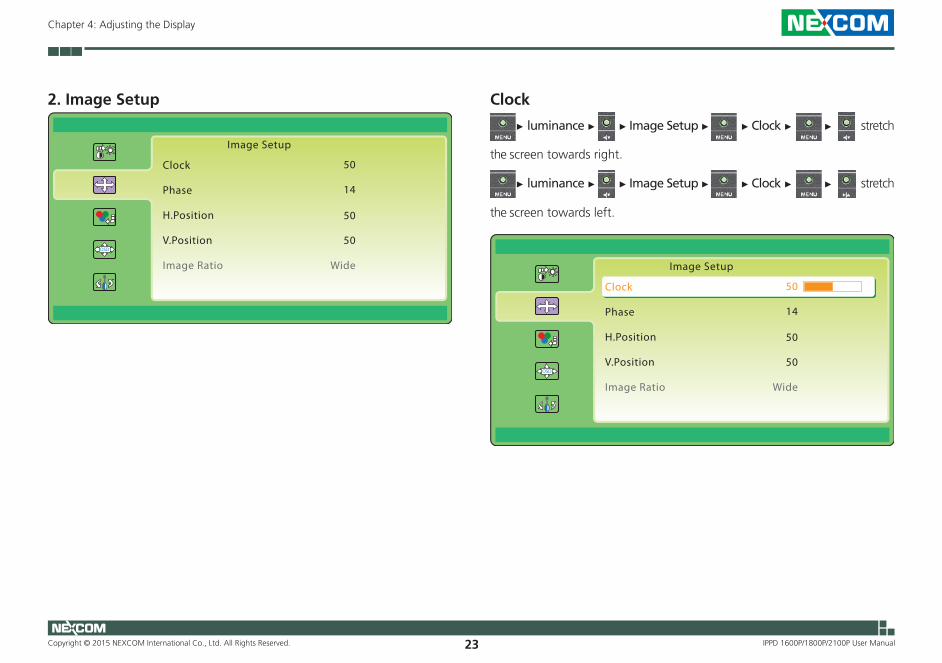
2. Image Setup
OSD
Image Setup
14
50Clock
Phase
H.Position
V.Position
Image Ratio
50
Wide
50
OSD
Image Setup
14
50Clock
Phase
H.Position
V.Position
Image Ratio
50
Wide
50
Clock
► luminance ► ► Image Setup ► ► Clock ► ► stretch
the screen towards right.
► luminance ► ► Image Setup ► ► Clock ► ► stretch
the screen towards left.
Copyright © 2015 NEXCOM International Co., Ltd. All Rights Reserved. 24
Chapter 4: Adjusting the Display
IPPD 1600P/1800P/2100P User Manual
OSD
Image Setup
14
50Clock
Phase
H.Position
V.Position
Image Ratio
50
Wide
50
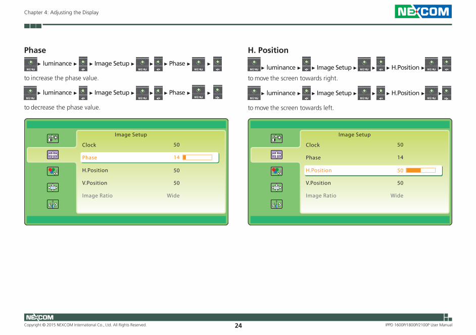
H. Position
► luminance ► ► Image Setup ► ► ► H.Position ► ►
to move the screen towards right.
► luminance ► ► Image Setup ► ► ► H.Position ► ►
to move the screen towards left.
OSD
Image Setup
14
50Clock
Phase
H.Position
V.Position
Image Ratio
50
Wide
50
Phase
► luminance ► ► Image Setup ► ► ► Phase ► ►
to increase the phase value.
► luminance ► ► Image Setup ► ► ► Phase ► ►
to decrease the phase value.
Copyright © 2015 NEXCOM International Co., Ltd. All Rights Reserved. 25
Chapter 4: Adjusting the Display
IPPD 1600P/1800P/2100P User Manual
OSD
Image Setup
14
50Clock
Phase
H.Position
V.Position
Image Ratio
50
Wide
50
OSD
Image Setup
14
50Clock
Phase
H.Position
V.Position
Image Ratio
50
Wide
50
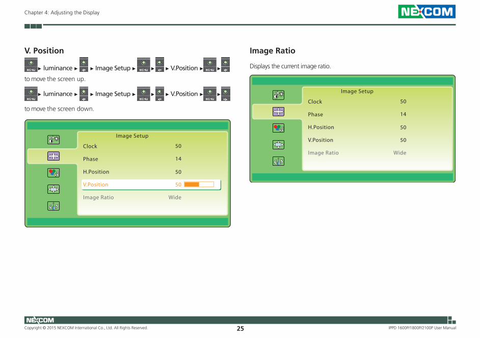
V. Position
► luminance ► ► Image Setup ► ► ► V.Position ► ►
to move the screen up.
► luminance ► ► Image Setup ► ► ► V.Position ► ►
to move the screen down.
Image Ratio
Displays the current image ratio.

Copyright © 2015 NEXCOM International Co., Ltd. All Rights Reserved. 26
Chapter 4: Adjusting the Display
IPPD 1600P/1800P/2100P User Manual
OSD
Color Temp.
51
◄ Warm ►Color Temp.
Red
Green
Blue
49
50
3. Color Temperature
OSD
Color Temp
51
WarmColor Temp.
Red
Green
Blue
49
50
Color Temperature
► luminance ► ► Color Temp. ► ► Color Temp. ► ►
to scroll right to change between the Color Temp. settings.
► luminance ► ► Color Temp. ► ► Color Temp. ► ►
to scroll left to change between the Color Temp. settings.
The following color temperature options are available: Warm, Normal, Cool, User and sRGB. To configure the RGB values manually, select User from the Color Temp. options.
Copyright © 2015 NEXCOM International Co., Ltd. All Rights Reserved. 27
Chapter 4: Adjusting the Display
IPPD 1600P/1800P/2100P User Manual
OSD
Color Temp.
50
UserColor Temp.
Red
Green
Blue
50
50
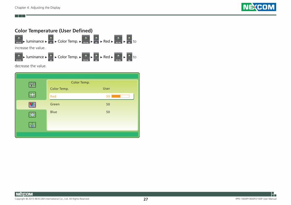
Color Temperature (User Defined)
► luminance ► ► Color Temp. ► ► ► Red ► ► to
increase the value.
► luminance ► ► Color Temp. ► ► ► Red ► ► to
decrease the value.

Copyright © 2015 NEXCOM International Co., Ltd. All Rights Reserved. 28
Chapter 4: Adjusting the Display
IPPD 1600P/1800P/2100P User Manual
4. OSD Setup
OSD
OSD Setup
50
50H.Position
V.Position
Timeout
Language
100
English
H. Position
► luminance ► ► OSD Setup ► ► H.Position ► ►
to move the OSD screen towards right.
► luminance ► ► OSD Setup ► ► H.Position ► ►
to move the OSD screen towards left.
OSD
OSD Setup
50
50H.Position
V.Position
Timeout
Language
100
English

Copyright © 2015 NEXCOM International Co., Ltd. All Rights Reserved. 29
Chapter 4: Adjusting the Display
IPPD 1600P/1800P/2100P User Manual
V. Position
► luminance ► ► OSD Setup ► ► ► V.Position ► ►
to move the OSD screen up.
► luminance ► ► OSD Setup ► ► ► V.Position ► ►
to move the OSD screen down.
Timeout
► luminance ► ► OSD Setup ► ► ► Timeout ► ►
to increase the OSD screen timeout value.
► luminance ► ► OSD Setup ► ► ► Timeout ► ►
to decrease the OSD screen timeout value.
OSD
OSD Setup
50
50H.Position
V.Position
Timeout
Language
100
EnglishOSD
OSD Setup
50
50H.Position
V.Position
Timeout
Language
100
English

Copyright © 2015 NEXCOM International Co., Ltd. All Rights Reserved. 30
Chapter 4: Adjusting the Display
IPPD 1600P/1800P/2100P User Manual
Language
► luminance ► ► OSD Setup ► ► ► Language ► ►
to scroll right to change between the language settings.
► luminance ► ► OSD Setup ► ► ► Language ► ►
to scroll left to change between the language settings.
OSD
OSD Setup
50
50H.Position
V.Position
Timeout
Language
100
English
The following languages are available: English, Simplified Chinese, Traditional Chinese, Korean, Russian, Portuguese, French and Spanish.

Copyright © 2015 NEXCOM International Co., Ltd. All Rights Reserved. 31
Chapter 4: Adjusting the Display
IPPD 1600P/1800P/2100P User Manual
5. Extra
OSD
Extra
On
D-SUBInput Select
DDC/CI
Reset
InformationResolution 1366(H) x 768 (V)H.Frequency: 48KHzV.Frequency: 60Hz
Yes
Input Select
► luminance ► ► Extra ► ► Input Select ► ►
to scroll right to change between D-SUB, DisplayPort or DVI as input.
► luminance ► ► Extra ► ► Input Select ► ►
to scroll left to change between D-SUB, DisplayPort or DVI as input.
OSD
Extra
On
◄ D-SUB ►Input Select
DDC/CI
Reset
InformationResolution 1366(H) x 768 (V)H.Frequency: 48KHzV.Frequency: 60Hz
Yes

Copyright © 2015 NEXCOM International Co., Ltd. All Rights Reserved. 32
Chapter 4: Adjusting the Display
IPPD 1600P/1800P/2100P User Manual
DDC/CI
► luminance ► ► Extra ► ► ► DDC/CI ► ► to scroll
right to turn DDC/CI On or Off.
► luminance ► ► Extra ► ► ► DDC/CI ► ► to scroll
left to turn DDC/CI On or Off.
Reset
► luminance ► ► Extra ► ► ► Reset ► ► or
to scroll to YES to restore factory default settings, or NO to abort it.
OSD
Extra
◄ On ►
D-SUBInput Select
DDC/CI
Reset
InformationResolution 1366(H) x 768 (V)H.Frequency: 48KHzV.Frequency: 60Hz
YesOSD
Extra
On
D-SUBInput Select
DDC/CI
Reset
InformationResolution 1366(H) x 768 (V)H.Frequency: 48KHzV.Frequency: 60Hz
◄ No ►
Copyright © 2015 NEXCOM International Co., Ltd. All Rights Reserved. 33
Appendix A: Extended Display Identification Data Timing Support
IPPD 1600P/1800P/2100P User Manual
aPPendIx a: extended dIsPlay IdentIfICatIon data tImIng suPPort
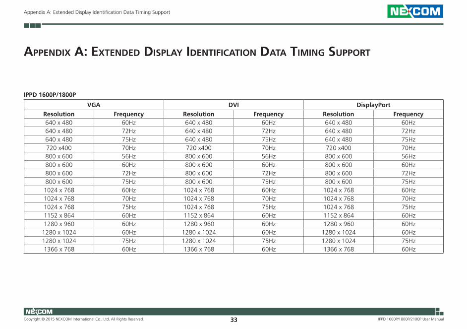
IPPD 1600P/1800P
VGA DVI DisplayPortResolution Frequency Resolution Frequency Resolution Frequency640 x 480 60Hz 640 x 480 60Hz 640 x 480 60Hz640 x 480 72Hz 640 x 480 72Hz 640 x 480 72Hz640 x 480 75Hz 640 x 480 75Hz 640 x 480 75Hz720 x400 70Hz 720 x400 70Hz 720 x400 70Hz800 x 600 56Hz 800 x 600 56Hz 800 x 600 56Hz800 x 600 60Hz 800 x 600 60Hz 800 x 600 60Hz800 x 600 72Hz 800 x 600 72Hz 800 x 600 72Hz800 x 600 75Hz 800 x 600 75Hz 800 x 600 75Hz1024 x 768 60Hz 1024 x 768 60Hz 1024 x 768 60Hz1024 x 768 70Hz 1024 x 768 70Hz 1024 x 768 70Hz1024 x 768 75Hz 1024 x 768 75Hz 1024 x 768 75Hz1152 x 864 60Hz 1152 x 864 60Hz 1152 x 864 60Hz1280 x 960 60Hz 1280 x 960 60Hz 1280 x 960 60Hz1280 x 1024 60Hz 1280 x 1024 60Hz 1280 x 1024 60Hz1280 x 1024 75Hz 1280 x 1024 75Hz 1280 x 1024 75Hz1366 x 768 60Hz 1366 x 768 60Hz 1366 x 768 60Hz
Copyright © 2015 NEXCOM International Co., Ltd. All Rights Reserved. 34
Appendix A: Extended Display Identification Data Timing Support
IPPD 1600P/1800P/2100P User Manual
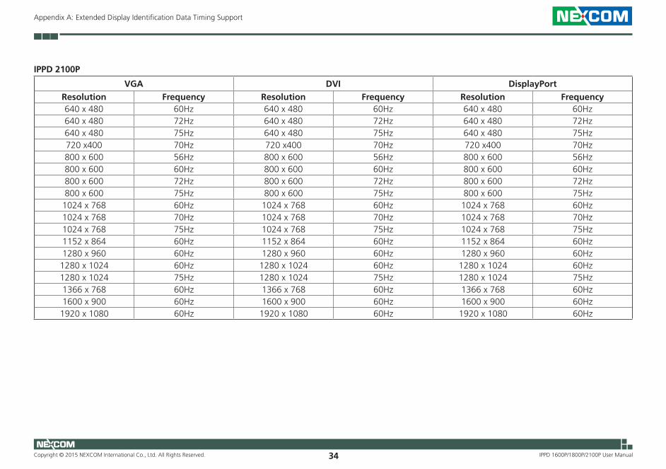
IPPD 2100P
VGA DVI DisplayPortResolution Frequency Resolution Frequency Resolution Frequency640 x 480 60Hz 640 x 480 60Hz 640 x 480 60Hz640 x 480 72Hz 640 x 480 72Hz 640 x 480 72Hz640 x 480 75Hz 640 x 480 75Hz 640 x 480 75Hz720 x400 70Hz 720 x400 70Hz 720 x400 70Hz800 x 600 56Hz 800 x 600 56Hz 800 x 600 56Hz800 x 600 60Hz 800 x 600 60Hz 800 x 600 60Hz800 x 600 72Hz 800 x 600 72Hz 800 x 600 72Hz800 x 600 75Hz 800 x 600 75Hz 800 x 600 75Hz1024 x 768 60Hz 1024 x 768 60Hz 1024 x 768 60Hz1024 x 768 70Hz 1024 x 768 70Hz 1024 x 768 70Hz1024 x 768 75Hz 1024 x 768 75Hz 1024 x 768 75Hz1152 x 864 60Hz 1152 x 864 60Hz 1152 x 864 60Hz1280 x 960 60Hz 1280 x 960 60Hz 1280 x 960 60Hz1280 x 1024 60Hz 1280 x 1024 60Hz 1280 x 1024 60Hz1280 x 1024 75Hz 1280 x 1024 75Hz 1280 x 1024 75Hz1366 x 768 60Hz 1366 x 768 60Hz 1366 x 768 60Hz1600 x 900 60Hz 1600 x 900 60Hz 1600 x 900 60Hz1920 x 1080 60Hz 1920 x 1080 60Hz 1920 x 1080 60Hz