Newsletter EnginSoft Year 7 n°2 - EnginSoft Flash · Newsletter EnginSoft Year 7 n°2 - 3 ......
60
Transcript of Newsletter EnginSoft Year 7 n°2 - EnginSoft Flash · Newsletter EnginSoft Year 7 n°2 - 3 ......


Newsletter EnginSoft Year 7 n°2 - 3
EnginSoft Flash
The 2010 Summer Edition of theNewsletter brings to our readers newsfrom the simulation community, theEnginSoft Network, our partners andcustomers in Europe and the USA. Thearticles and reviews on the followingpages reflect the diversity of Simulation,CAE and Virtual Prototyping acrossindustry, educational institutions andresearch. From automotive and aerospaceto electronics, from the petrochemicaland Oil&Gas sectors to materialsuppliers, today’s product developersand designers count on engineeringsimulation.
While it is one thing to provide state-of-the-art softwareand expertise, it is another to be ready to share and passon our knowledge, and to bring in our partners’ ideas,know-how and developments.
At EnginSoft, we communicate constantly with expertsinside and outside our Network. We believe thatNetworking is essential to further grow and deepen ourknowledge and hence the portfolio of services andproducts for our customers. To us: Networking is a keyfactor for innovation and success.
This is also what drives us to host the annual EnginSoftInternational Conference, this year from 21st – 22ndOctober at Fiera Montichiara/Brescia, Italy. TheConference will take place concurrently with the ANSYSItalian Users’ Meeting, it will offer to our guests uniqueinsights into current and future values of softwaretechnologies, fast ROI Return on Investment, and thelatest advancements and developments. The largeaccompanying exhibition will provide a perfect platformfor International Networking.
The Conference will reflect some of the contents of earlierevents of 2010 that we also present in this Newsletter: theInternational modeFRONTIER Users’ Meeting, the 4thPhilonNet CAE Conference, the NADIA Conference for theconclusion of the NADIA Project, and METEF, theInternational Aluminium and Foundry EquipmentExhibition where EnginSoft was awarded the “PREMIOINNOVAZIONE 2010”, the prize for Innovation 2010.
Furthermore, this Edition features a captivatinginterview with Alessandro Franzoni, CEO ofSuperjet International, Tim Morris and DavidQuinn of NAFEMS International give us theirviews on the Future of Engineering Analysis.We hear from APERIO, EnginSoft’srepresentation in Spain, and theircollaboration with the Master of TechnicalSpecialization in Racing Industry (METCA).Further news from Spain include a review of thepresentation day on process integration anddesign optimization organized by the AICAutomotive Intelligence Center in Bilbao.
Our case studies show how Continental AGimproved cost and magnetic efficiency, VTI
Technologies Oy used multi-objective optimization for aBall Grid Array, the CompMechLab of St.Petersburg’s StatePolytechnical University applied optimization to a springbearing. Eurotecnica presents a one-dimensional fluid-dynamic study of a molten salts thermal energy storagesystem and Sapa Group reports on the successful use ofANSYS for their developments.
Our software column highlights ANSYS Maxwell, ANSYSSTR, Scilab for thermo-mechanical problems and Grapheur,a package of tools for modeling and visualizing byReactive Search.
The corporate news inform our readers about EnginSoft’slatest initiative in the United States with CascadeTechnologies and the companies’ strong ties withStandford University. Aprilia Racing welcomed EnginSoft’sengineers at the Superbike World Championship in Monza. This edition also provides updates on the Verdi (VirtualEngineering for Robust manufacturing with DesignIntegration) and Nadia Projects, our worldwide EventCalendar and other news.
To hear more and to discuss opportunities with EnginSoftand our partners, please meet us on 21st & 22nd Octoberat the Fiera Montichiari in Italy.
We look forward to welcoming you!
Stefano OdorizziEditor in chief
Ing. Stefano OdorizziEnginSoft CEO and President

4 - Newsletter EnginSoft Year 7 n°2
Sommario - Contents
6 2010 EnginSoft International Conference: Register fast to take advantage of the Early-Bird rates!
8 Multi-Objective Optimization of a Ball Grid Array of a capacitive MEMS
12 Design for Improved Cost & Magnetic Efficiency
15 Optimization of a Spring Bearing for Gravitational Forces Compensation
17 One-Dimensional Fluid-Dynamic Study of a Molten Salts Thermal Energy Storage System
19 Simulazione CFD di un filtro di Profondità per Trasfusioni
21 NIDIATA - An IMS-MPT Action promoted by EnginSoft
23 ANSYS Workbench: a multidisciplinary FEM approach for PCB equipment
26 Grapheur - A new vision for …Interactive Visualization
30 A simple Finite Element Solver for thermo-mechanical problems
35 EnginSoft interviews Alessandro Franzoni, CEO of Superjet International
39 Il Progetto VERDI: Virtual Engineering for Robust Manufacturing with Design Integration
42 The Future of Engineering Analysis: Pervasive Realistic Simulation
44 AperioTec and modeFRONTIER collaborate with METCA
46 Dr. Roberto Battiti, Reactive Search CTO meets with Cascade Technologies Inc, the new EnginSoft JointVenture in the US
47 Aprilia Racing welcomes EnginSoft to the 2010 Superbike World Championship in Monza
The EnginSoft Newsletter editions contain references to the followingproducts which are trademarks or registered trademarks of their respec-tive owners:ANSYS, ANSYS Workbench, AUTODYN, CFX, FLUENT and any and all
ANSYS, Inc. brand, product, service and feature names, logos and slogans are
registered trademarks or trademarks of ANSYS, Inc. or its subsidiaries in the
United States or other countries. [ICEM CFD is a trademark used by ANSYS,
Inc. under license]. (www.ANSYS.com)
modeFRONTIER is a trademark of ESTECO EnginSoft Tecnologie per
l’Ottimizzazione srl. (www.esteco.com)
Flowmaster is a registered trademark of The Flowmaster Group BV in the
USA and Korea. (www.flowmaster.com)
MAGMASOFT is a trademark of MAGMA GmbH. (www.magmasoft.com)
ESAComp is a trademark of Componeering Inc.
(www.componeering.com)
Forge and Coldform are trademarks of Transvalor S.A.
(www.transvalor.com)
AdvantEdge is a trademark of Third Wave Systems .
(www.thirdwavesys.com)
LS-DYNA® is a trademark of Livermore Software Technology Corporation.
(www.lstc.com)
SCULPTOR is a trademark of Optimal Solutions Software, LLC
(www.optimalsolutions.us)
Grapheur is a product of Reactive Search SrL, a partner of EnginSoft
For more information, please contact the Editorial Team
CASE STUDIES
IN DEPTH STUDIES
INTERVIEWS
SOFTWARE NEWS
CORPORATE NEWS
RESEARCH AND TECHNOLOGY TRANSFER

Newsletter EnginSoftYear 7 n°2 - Summer 2010To receive a free copy of the next EnginSoft
Newsletters, please contact our Marketing office at:
All pictures are protected by copyright. Any reproduction
of these pictures in any media and by any means is
forbidden unless written authorization by EnginSoft has
been obtained beforehand.
©Copyright EnginSoft Newsletter.
AdvertisementFor advertising opportunities, please contact our
Marketing office at: [email protected]
EnginSoft S.p.A.24124 BERGAMO Via Galimberti, 8/D
Tel. +39 035 368711 • Fax +39 0461 979215
50127 FIRENZE Via Panciatichi, 40
Tel. +39 055 4376113 • Fax +39 055 4223544
35129 PADOVA Via Giambellino, 7
Tel. +39 49 7705311 • Fax 39 049 7705333
72023 MESAGNE (BRINDISI) Via A. Murri, 2 - Z.I.
Tel. +39 0831 730194 • Fax +39 0831 730194
38123 TRENTO fraz. Mattarello - via della Stazione, 27
Tel. +39 0461 915391 • Fax +39 0461 979201
www.enginsoft.it - www.enginsoft.com
e-mail: [email protected]
COMPANY INTERESTSESTECO EnginSoft Tecnologie per l’Ottimizzazione
34016 TRIESTE Area Science Park • Padriciano 99
Tel. +39 040 3755548 • Fax +39 040 3755549
www.esteco.com
CONSORZIO TCN
38123 TRENTO Via della Stazione, 27 - fraz. Mattarello
Tel. +39 0461 915391 • Fax +39 0461 979201
www.consorziotcn.it
EnginSoft GmbH - Germany
EnginSoft UK - United Kingdom
EnginSoft France - France
EnginSoft Nordic - Sweden
Aperio Tecnologia en Ingenieria - Spain
www.enginsoft.com
ASSOCIATION INTERESTSNAFEMS International
www.nafems.it
www.nafems.org
TechNet Alliance
www.technet-alliance.com
RESPONSIBLE DIRECTOR
Stefano Odorizzi - [email protected]
PRINTING
Grafiche Dal Piaz - Trento
The EnginSoft NEWSLETTER is a quarterly magazine published by EnginSoft SpA
Newsletter EnginSoft Year 7 n°2 - 5
Auto
rizz
azio
ne d
el T
ribu
nale
di
Tren
to n
° 13
53 R
S di
dat
a 2/
4/20
08
48 L’esperienza di un leader mondiale: Sapa
49 EnginSoft partecipa al METEF 2010
50 Manuale della difettologia nei getti pressocolati
50 EnginSoft riceve il Premio Innovazione Metef2010 nella categoria Prodotti, Componenti e Sistemi
51 CONFERENZA NADIA Leghe leggere per l’automotive: lesfide del Progetto NADIA
52 4th PhilonNet CAE Conference
54 International modeFRONTIER Users’ Meeting 2010
55 EnginSoft at the modeFRONTIER International Users’Meeting 2010
56 APMS 2010 Third Announcement and Call for Papers
57 Multi-Disciplinary Methodology for Process Integrationand Design Optimization: a presentation day organized bythe Automotive Intelligence Center (AIC) in Amorebieta-Bilbao.
58 EnginSoft Event Calendar
59 EnginSoft UK Seminar Review
TESTIMONIAL
PAGE 26 GRAPHEUR - A NEW
VISION FOR… INTERACTIVE
VISUALIZATION
EVENTS
PAGE 35 ENGINSOFT INTERVIEWS
ING. FRANZONI (SUPERJET INTERNATIONAL)
PAGE 8 MULTI-OBJECTIVE
OPTIMIZATION OF A BALL GRID
ARRAY OF CAPACITIVE MEMS

For more than 20 years, the EnginSoft InternationalConference on “CAE Technologies for Industry” has been thereference event for the VP community in Italy. TheConference offers unique insights into current and futurevalues of software technologies, background trends,outstanding achievements, groundbreaking scientificdevelopments and the visions of those who realizeadvancements. The Conference reflects and meets industryneeds on different levels, from the perspective of managersand decision makers, technical experts, software users up tohuman resources analysts.
and additional Conference Highlights which include:• a Think Tank bringing together executives from industry,
research, academia and technology providers, to fosterthe understanding of engineering simulation and itsimpact on the future and success of your business;
• a Panel of simulation-based engineering, science andtechnology experts. The panel will document how recentand future technical developments should improveaccuracy, reliability, accessibility and applicability ofengineering simulation results, as well as computationalspeed;
• an exhibition, unprecedented in this sector in Italy,where leading providers of CAE and VP Technologies willshowcase their latest solutions and share their visionsand strategies;
• an informal environment for delegates, technologyproviders, managers and experts to meet and exchangeexperiences, address key industry issues and challenges,and explore new business opportunities.
Do not miss the ideal occasion to discuss today'slimitless applications of “simulation based engineering
and sciences” in the true sense of the conference motto:“Believe in innovation: simulate the world”
The conference takes place concurrently with the ANSYSItalian Users’ Meeting. ANSYS is the major partner ofEnginSoft, and the leading global provider of engineeringsimulation technologies. The conference will therefore be ofutmost interest to the community of ANSYS users.
2010 EnginSoft International ConferenceCAE TECHNOLOGIES FOR INDUSTRY
AND ANSYS ITALIAN CONFERENCEfIERA MONTICHIARI (BS) - ITALY - 21-22 OCTOBER 2010
INVITATION & 2nd ANNOUNCEMENTRegister fast to take advantage of the Early-Bird rates!
www.caeconference.com
Conference delegates are invited to attendall Program Sessions:Plenary – Mechanical Engineering – CFD – HighFrequency – Optimization Technologies –Design Chain Technologies – Casting Processes– Forging Processes
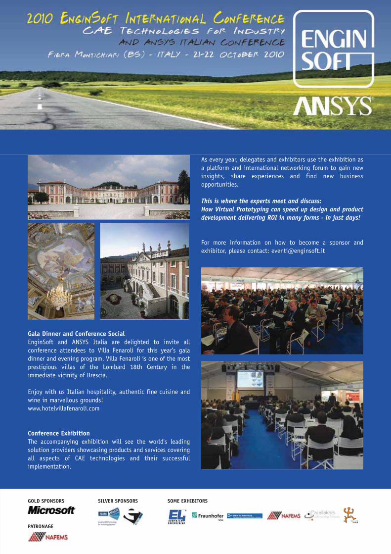
Gala Dinner and Conference SocialEnginSoft and ANSYS Italia are delighted to invite allconference attendees to Villa Fenaroli for this year’s galadinner and evening program. Villa Fenaroli is one of the mostprestigious villas of the Lombard 18th Century in theimmediate vicinity of Brescia.
Enjoy with us Italian hospitality, authentic fine cuisine andwine in marvellous grounds!www.hotelvillafenaroli.com
Conference Exhibition The accompanying exhibition will see the world's leadingsolution providers showcasing products and services coveringall aspects of CAE technologies and their successfulimplementation.
As every year, delegates and exhibitors use the exhibition asa platform and international networking forum to gain newinsights, share experiences and find new businessopportunities.
This is where the experts meet and discuss:How Virtual Prototyping can speed up design and productdevelopment delivering ROI in many forms - in just days!
For more information on how to become a sponsor andexhibitor, please contact: [email protected]
GOLD SPONSORS SILVER SPONSORS SOME EXHIBITORS
PATRONAGE

8 - Newsletter EnginSoft Year 7 n°2
Multi-Objective Optimization of a BallGrid Array of a capacitive MEMS
1. IntroductionVTI Technologies Oy develops and manufactures micro electromechanical systems (MEMS) and the main products arecapacitive low-g accelerometers which for instance are usedin automotive electronic stability control (ESC) systems. Anaccelerometer is attached to the printed circuit board (PCB)by an array of solder balls. The attachment type is referred toas a ball grid array (BGA) due to the shape and layout of thesolder balls (Figure 1).The measurement principle for a low-g accelerometer isoutlined in Figure 2. A mass is attached to an anchor via aspring, and under acceleration the mass which holds thesensing electrodes moves with respect to the staticelectrodes. The movement changes the gap and thus thecapacitance which is then measured. The final product whichis soldered to the PCB includes multiple materials, each witha different thermal expansion coefficient. Unfortunately thismay cause the sensing elements to move as change and sendout a false acceleration output, referred to as an offset error.
Accelerometers are normally exposed to small vibrationswhich may cause fatigue and failure of the electricalconnection between the accelerometer and the PCB. Both theoffset error and the fatigue life are affected by the layout ofthe BGA and the objective of the study is therefore tominimize the offset error and, at the same time, maximizethe expected service life.
2. The numerical modelIn order to keep the model size reasonable, the active sensorelements were not included in the FEM model. We assume themovement of the anchors can be directly mapped to theoffset error, i.e. the larger the movement, the larger theoffset error as a function of temperature. Mesh controls were employed to ensure dense mesh in criticalparts of the model and to achieve a consistent mesh betweendifferent geometries. Ten noded tetrahedral elements wereused in the linear model and typical model size was 400000elements or 1.65 million degrees of freedom. Plasticity and
Figure 1 - The baseline design of the ball grid array is evenly spread overthe available surface. The MEMS structure may be seen behind the graysolder balls.
Figure 2 - A low-g accelerometer measures the change in capacitance withvarying gap size. The gap, typically 1.5 to 3 μm, changes when accelerationforces move the mass.
Capacitive MEMS accelerometers may be directly soldered to the printed circuit board by an array ofsolder balls. Differences in the thermal expansion coefficients of the pertinent materials causedeformations of the accelerometer under temperature change. This may cause a relative movement ofthe sensing masses with respect to the sensing electrodes, resulting in a change in capacitance and afalse acceleration output. A multi-objective optimization was used to find the best location of the solderballs which minimized the measurement error under varying temperature and, at the same time,maximized the expected service life due to fatigue of the solder balls. While the achieved improvementin service life was moderate, an order of magnitude improvement was achieved for the predictedmeasurement error.

Newsletter EnginSoft Year 7 n°2 - 9
creep of the solder was omitted and two load cases withdifferent temperature were used, +85°C and –40°C.Figure 3 displays a part of the meshed model, the solder ballson the PCB.
3. Multi-objective optimizationThe general multi-objectiveoptimization software modeFRONTIERwas used to automate the designevaluations and steer the processtowards its optimum. The generalizedprocess has been outlined in Figure 4and consists of setting inputparameters, running the simulation,reading the results and deciding whichdesign to evaluate next. The loop isthen repeated until the optimum hasbeen found or, more commonly, good enough results areobtained and resources are needed better elsewhere.
3.1 What to measureAn optimization task always starts with the definition of theobjectives and how to measure them. The selected resultshould in a single number capture how well the designperforms with respect to the objective. In this case the valuefunction Ftot was a measure of the relative movement of theanchors of the sensing and static electrodes:
where the average displacement of the top surface of ananchor is defined as
The sensor was identified through i=1,2,3,4 and j=1,…,6identifies the anchor within the sensor, see figure 5. Sensorsi=1,3 measure in the x-direction and sensors i=2,4 in the y-direction. u is the x-displacement for i=1,3 and the y-displacement for i=2,4. To maximize the service life, one aims to minimize the solderfatigue through minimizing the peak stress in the solderballs.
3.2 Parameterization of the BGA layoutIt was desirable to investigate a large design space whichincluded fundamentally different designs compared to thebaseline, see figure 6. For that reason the parameterizationhad to be very general, allowing each solder ball to movefreely over most of the surface, see figure 7.
In order to take manufacturing constraints into account, theminimum allowed distance between center to center of twosolder balls was increased from 330 μm, respecting only thesolder balls, to 500 μm.
3.3 Process automationEach design candidate was evaluated in an automaticprocess, including import of CAD geometry and moving eachsolder ball to the specified location. The design was thenmeshed, solved and the offset error, as well as the stresses,was extracted. Based on the log files, a command file in
Matlab format was assembled which carried outthe process above. The command file includedthe move command of each solder ball as wellas a set of custom postprocessing commands.Besides saving the specified results to an asciifile, several plots of interesting results weresaved for continuous monitoring. In order to capture designs where solder ballswere located too close, a collision detectioncheck was implemented directly inmodeFRONTIER. As can be seen in figure 8,each design candidate is first checked forcollisions. Only designs with zero collisions arepassed on to the solver for evaluation.
The optimization was run on a 64-bit Linux system and thesolution time for a design evaluation varied from 9 to 15minutes.
4. Optimization strategyIn order to allow BGA design layouts which were verydifferent from the baseline design, the range of each inputparameter had to be wide. It was therefore not possible toavoid collisions. As the collision check stops impossibledesigns from being evaluated, the learning process of theoptimization algorithm is slowed down.
A good choice for this type of situation is the Multi-ObjectiveGenetic Algorithm (MOGA-II), one of the most popularalgorithms available in modeFRONTIER. By using apopulation of designs, it mimics the genetic mechanisms
Figure 3 - The solder balls, seen on top of the PCB, have a refined mesh.
Figure 5 - Anchors and their numberingwithin one of the sensors measuring in they-direction.
Figure 6 -- t was desirable to try out very different BGA layouts such as theexample on the right, compared to the baseline design to the left.
10 - Newsletter EnginSoft Year 7 n°2
found in nature to search for the best designs. Here, aninitial population of about 50 designs would be suitable.
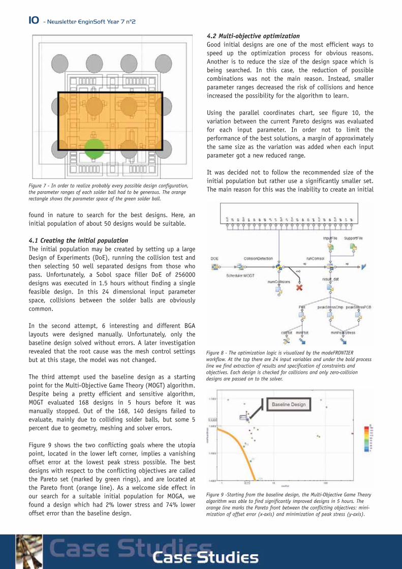
4.1 Creating the initial populationThe initial population may be created by setting up a largeDesign of Experiments (DoE), running the collision test andthen selecting 50 well separated designs from those whopass. Unfortunately, a Sobol space filler DoE of 256000designs was executed in 1.5 hours without finding a singlefeasible design. In this 24 dimensional input parameterspace, collisions between the solder balls are obviouslycommon.
In the second attempt, 6 interesting and different BGAlayouts were designed manually. Unfortunately, only thebaseline design solved without errors. A later investigationrevealed that the root cause was the mesh control settingsbut at this stage, the model was not changed.
The third attempt used the baseline design as a startingpoint for the Multi-Objective Game Theory (MOGT) algorithm.Despite being a pretty efficient and sensitive algorithm,MOGT evaluated 168 designs in 5 hours before it wasmanually stopped. Out of the 168, 140 designs failed toevaluate, mainly due to colliding solder balls, but some 5percent due to geometry, meshing and solver errors.
Figure 9 shows the two conflicting goals where the utopiapoint, located in the lower left corner, implies a vanishingoffset error at the lowest peak stress possible. The bestdesigns with respect to the conflicting objectives are calledthe Pareto set (marked by green rings), and are located atthe Pareto front (orange line). As a welcome side effect inour search for a suitable initial population for MOGA, wefound a design which had 2% lower stress and 74% loweroffset error than the baseline design.
4.2 Multi-objective optimizationGood initial designs are one of the most efficient ways tospeed up the optimization process for obvious reasons.Another is to reduce the size of the design space which isbeing searched. In this case, the reduction of possiblecombinations was not the main reason. Instead, smallerparameter ranges decreased the risk of collisions and henceincreased the possibility for the algorithm to learn.
Using the parallel coordinates chart, see figure 10, thevariation between the current Pareto designs was evaluatedfor each input parameter. In order not to limit theperformance of the best solutions, a margin of approximatelythe same size as the variation was added when each inputparameter got a new reduced range.
It was decided not to follow the recommended size of theinitial population but rather use a significantly smaller set.The main reason for this was the inability to create an initial
Figure 7 - In order to realize probably every possible design configuration,the parameter ranges of each solder ball had to be generous. The orangerectangle shows the parameter space of the green solder ball.
Figure 8 - The optimization logic is visualized by the modeFRONTIER workflow. At the top there are 24 input variables and under the bold processline we find extraction of results and specification of constraints and objectives. Each design is checked for collisions and only zero-collisiondesigns are passed on to the solver.
Figure 9 -Starting from the baseline design, the Multi-Objective Game Theoryalgorithm was able to find significantly improved designs in 5 hours. Theorange line marks the Pareto front between the conflicting objectives: mini-mization of offset error (x-axis) and minimization of peak stress (y-axis).

Newsletter EnginSoft Year 7 n°2 - 11
population with non-colliding BGA layouts from all regions ofthe input design space. The 10 best designs of the MOGToptimization were therefore chosen, trusting that MOGAwould make a steady evolution towards better designs whileavoiding colliding BGA layouts.The strategy worked and MOGA evaluates 990 new designs ofwhich 759 completed successfully in 5 days. As can be seenin figure 11, the Pareto front has been stretched out andfilled with more designs. While the stress levels weremoderately improved compared to the first optimization, theoffset error was now close to being eliminated.
5. ResultsAn extended Pareto front was found which showedimprovements in both objectives compared to the baselinedesign. As always in multi-objective optimization, there is nosingle best design but rather a set of trade-off designsbetween the conflicting objectives. The best design withrespect to peak stress had 14% lower stress and 15% loweroffset error. The best design with respect to offset error had5% lower stress and 99% lower offset error compared to thebaseline design.
Figure 12 shows the shear stress in two planes, close to thePCB and close to the MEMS chip. Close to the chip, the
stresses appear to concentrate on the balls in the corners ofthe grid. The achieved reduction in the offset error by two decades isa significant improvement to the temperature stability incomparison with the base line design.
ConclusionsThe presented work has showed that the offset error may beclose to eliminated. In order to increase the accuracy of themodel a capacitance calculation should be included. Thisenables minimization of computed offset error inacceleration units instead of the current anchordisplacements.Manufacturability may also be studied by analysing thesensitivity of the results due to small changes in the locationof the solder balls. In other words, we are looking for arobust global optimum.An order of magnitude improvement in measurement errorwas achieved which may validate the sensor to a wider rangeof applications which are demanding with respect tospecified offset error.
H. Strandberg - ESTECO Nordic ABT. Makkonen2, J. Leinvuo - VTI Technologies Oy
For more informationHåkan Strandberg - ESTECO Nordic [email protected]
Figure 10 - The parallel coordinates chart shows both objectives and theinput parameters in the same diagram for the 4 Pareto designs. Compared tothe specified input ranges, showed by the full height of the axes, the Paretodesigns are concentrated to a narrow zone. Based on this, the parameterranges were reduced before starting the MOGA optimization.
Figure 11 - The multi-objective optimization aims to reveal the Pareto front,marked by the orange line. The marked designs in the lower left cornerrepresent the best trade-off designs between offset error and service life.Note the two zones with accumulation of designs which indicate some issuewith the analysis.
Figure 12 - Shear stress in the plane close to the PCB (upper) and the MEMSchip (lower)

Design for Improved Cost & MagneticEfficiencyPerformance Optimization of a Gasoline Injector
12 - Newsletter EnginSoft Year 7 n°2
Gasoline InjectorThe injector is a valve that has to controland adjust the gasoline flow in order togenerate the required mixture for the EngineControl Unit (ECU).
The Gasoline injectors are mainly dividedinto two different groups: low pressure andhigh pressure applications depending on ifthe injection is performed into themanifold, or directly into the combustionchamber in the pressurizing phase.
The most common injector technology isSolenoid activated. A current signal (ECUcontrol) (I(t)) generates a magnetic fieldinto a magnetic components circuit (ø(t))which generates a force between twocomponents (F(t)). This force generates themovement of a movable component (lift(t))which opens a nozzle generating the Flowrate (Q(t)) and Spray (Fig. 1).In this work, we studied the currentContinental Solenoid injector for DirectGasoline Injection, named XL2 (Fig. 1), andsome of the possible variations.
Figure 1 - SDI XL2 Injector
Figure 2 - XL2-DTC Project – Organization & Risks
Due to the worldwide economic crisis and falling production numbers in the automotive industry, manysuppliers have implemented new strategies and actions with the aim of reducing costs and the impactof the crisis on their plants. In this context, Continental defined and started a “Design-to-Cost Project”for the latest Continental Solenoid Direct Gasoline Injector (XL2). A number of possible modifications were identified with a new Injector Layout. This new Layout includedimportant changes in the components of the magnetic circuit of the injector. At the beginning, due toweak magnetic performances, the new Design-to-Cost Layout was not acceptable from a technical pointof view. However, after a first development phase, modeFRONTIER was implemented in order to reachthe targets for the Complete Layout magnetic performances. A parametric magnetic circuit model of theinjector in Emag (ANSYS) and a Workflow in modeFRONTIER were created. This new approach helped the Continental Engineering Team to achieve best performances of themagnetic behavior of the new layout and to obtain technical approval for further development. Theproject also revealed the advantages of using modeFRONTIER, an automatic CAE optimizer, for reducingtime and cost, in comparison with the previous standard procedure.

Newsletter EnginSoft Year 7 n°2 - 13
Project & RisksWith the economic crisis and fallen production numbers in theautomotive industry in mind, Continental started a Design-to-Cost Project (DTC) with the primary objective to decrease thematerial cost of the injector, the XL2 SDI product.
Their Project Manager and the three Product Engineers (PE)responsible for the three different component sub-groups(Fig. 2) defined a Project Chart.
It was clear that the design work of all three component sub-groups would have a strong impact on the magneticperformances of the injector. Hence, the risk was that if eachPE would work on its own, not sharing results with the others,it might be impossible in the end to define guidelines whichmatch the other PE’s strategies.To avoid this, after a preliminarydevelopment phase without sufficientreliable results, a Complete LayoutOptimization was suggested to solve theproblem. Continental could benefit immediatelyfrom the advantages of this newapproach: • low mistake rate due to automated
processes, • possibility to reach best
performances with an optimizationalgorithm,
• high number of simulations and lownumber of samples reducing time andcost of the Concept Definition phase.
Technical ActivitiesA package of changes was defined which is describedin Fig.3. Two components with different magneticcharacteristics (1 non-magnetic) were merged intoone magnetic component. The shape of the mergedcomponent was modified from the initial one and newdimensions were defined for another component(Armature). Moreover, the possible impact on coilshape and position was identified. These changesdelivered by the DTC also proved to have aconsiderable impact on the magnetic performances ofthe injector.
Fig. 7 highlights the performances of the currentproduct (left red bars) and the previous injector.
When we look at the initial performances of the DTC Layoutcompared to the current product (Fig. 7 left red bars), it isobvious that the previous design was not feasible and amagnetic optimization was needed. A Parametric Model wasdefined using 12 parameters as described in Fig. 4.
The Simulations were done with an axial-symmetric model inANSYS Emag using different B-h curves (magneticcharacteristics) of each material. The input of a generic
simulation was a current signal (I(t)), and the output is theforce profile at constant lift (F(t) at lift=cost.) (Fig.1 andFig.5). While, in this way, it is not possible to compute thecomplete dynamics of the injector, the magneticperformances of the configurations could be compared. For
Figure 3 - Design To Cost Changes description
Figure 4 - Parametric Model
Figure 5 - Simulation Description
14 - Newsletter EnginSoft Year 7 n°2
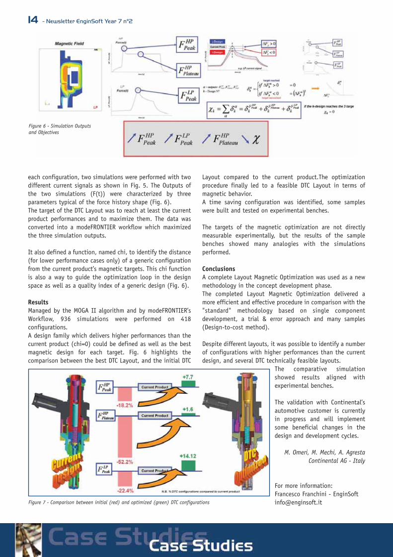
each configuration, two simulations were performed with twodifferent current signals as shown in Fig. 5. The Outputs ofthe two simulations (F(t)) were characterized by threeparameters typical of the force history shape (Fig. 6). The target of the DTC Layout was to reach at least the currentproduct performances and to maximize them. The data wasconverted into a modeFRONTIER workflow which maximizedthe three simulation outputs.
It also defined a function, named chi, to identify the distance(for lower performance cases only) of a generic configurationfrom the current product’s magnetic targets. This chi functionis also a way to guide the optimization loop in the designspace as well as a quality index of a generic design (Fig. 6).
ResultsManaged by the MOGA II algorithm and by modeFRONTIER’sWorkflow, 936 simulations were performed on 418configurations. A design family which delivers higher performances than thecurrent product (chi=0) could be defined as well as the bestmagnetic design for each target. Fig. 6 highlights thecomparison between the best DTC Layout, and the initial DTC
Layout compared to the current product.The optimizationprocedure finally led to a feasible DTC Layout in terms ofmagnetic behavior. A time saving configuration was identified, some sampleswere built and tested on experimental benches.
The targets of the magnetic optimization are not directlymeasurable experimentally, but the results of the samplebenches showed many analogies with the simulationsperformed.
ConclusionsA complete Layout Magnetic Optimization was used as a newmethodology in the concept development phase.The completed Layout Magnetic Optimization delivered amore efficient and effective procedure in comparison with the"standard" methodology based on single componentdevelopment, a trial & error approach and many samples(Design-to-cost method).
Despite different layouts, it was possible to identify a numberof configurations with higher performances than the currentdesign, and several DTC technically feasible layouts.
The comparative simulationshowed results aligned withexperimental benches.
The validation with Continental’sautomotive customer is currentlyin progress and will implementsome beneficial changes in thedesign and development cycles.
M. Omeri, M. Mechi, A. Agresta Continental AG - Italy
For more information:Francesco Franchini - EnginSoft [email protected]
Figure 6 - Simulation Outputs and Objectives
Figure 7 - Comparison between initial (red) and optimized (green) DTC configurations
Newsletter EnginSoft Year 7 n°2 - 15
Optimization of a Spring Bearing forGravitational Force Compensation
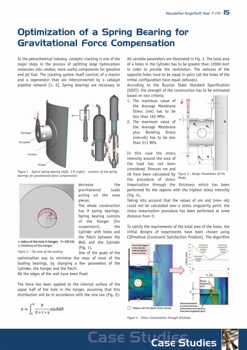
In the petrochemical industry, catalytic cracking is one of themajor steps in the process of splitting large hydrocarbonmolecules into smaller, more useful components for gasolineand jet fuel. The cracking system itself consists of a reactorand a regenerator that are interconnected by a catalystpipeline network [1, 2]. Spring bearings are necessary to
decrease thegravitational loadsacting on the nosepieces. The whole constructionhas 9 spring bearings.Spring bearing consistsof the Hanger (forsuspension), theCylinder with holes andthe Patch between theWall and the Cylinder(Fig. 1).One of the goals of the
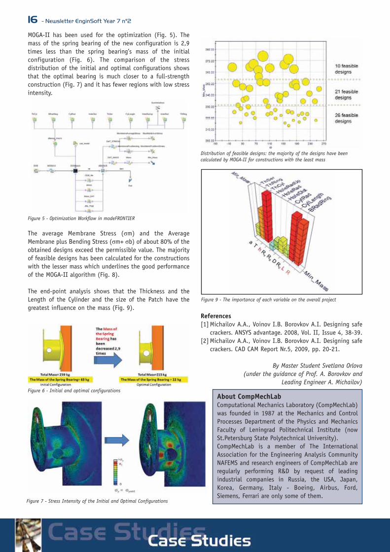
optimization was to minimize the mass of most of theloading bearings, by changing a few parameters of theCylinder, the Hanger and the Patch.All the edges of the wall have been fixed.
The force has been applied to the internal surface of theupper half of the hole in the hanger, assuming that thisdistribution will be in accordance with the sine law (Fig. 2):
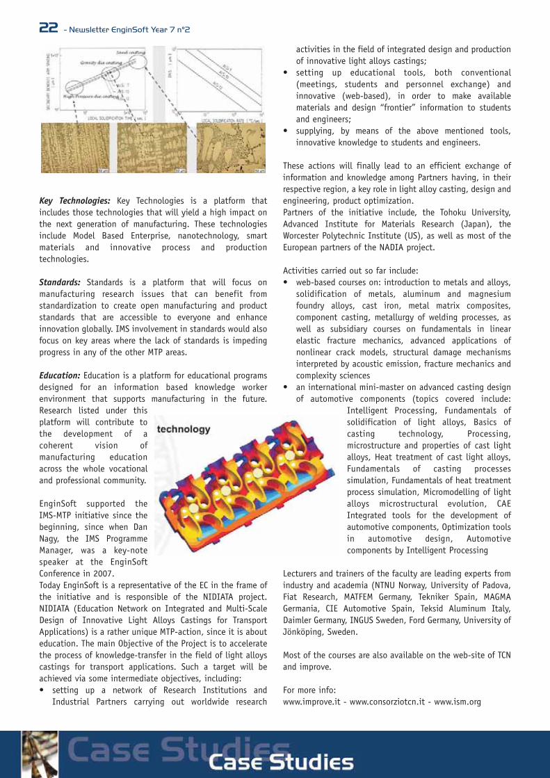
All variable parameters are illustrated in Fig. 3. The total areaof 4 holes in the Cylinder has to be greater than 12000 mm²in order to provide the ventilation. The radiuses of theopposite holes have to be equal in pairs (all the holes of theinitial configuration have equal radiuses).According to the Russian State Standard Specification(GOST), the strength of the construction has to be estimatedbased on two criteria:1. The maximum value of
the Average MembraneStress (σm) has to beless than 162 MPa;
2. The maximum value ofthe Average Membraneplus Bending Stress(σm+σb) has to be lessthan 211 MPa.
In this case the stressintensity around the area ofthe load has not beenconsidered. Stresses σm andσb have been calculated bythe procedure of stresslinearization through the thickness which has beenperformed for the regions with the highest stress intensity(Fig. 4). Taking into account that the values of σm and (σm+ σb)could not be calculated near a stress singularity point, thestress linearization procedure has been performed at somedistance from it.
To satisfy the requirements of the total area of the holes, theinitial designs of experiments have been chosen usingCSPmethod (Constraint Satisfaction Problem). The Algorithm
Figure 1 - Typical spring bearing (left). 1-9 (right) - Location of the springbearings for gravitational force compensation
Figure 2 - The area of the loading
Figure 3 - Design Parameters of theModel
Figure 4 - Stress Linearization through thickness
16 - Newsletter EnginSoft Year 7 n°2
MOGA-II has been used for the optimization (Fig. 5). Themass of the spring bearing of the new configuration is 2,9times less than the spring bearing’s mass of the initialconfiguration (Fig. 6). The comparison of the stressdistribution of the initial and optimal configurations showsthat the optimal bearing is much closer to a full-strengthconstruction (Fig. 7) and it has fewer regions with low stressintensity.
The average Membrane Stress (σm) and the AverageMembrane plus Bending Stress (σm+ σb) of about 80% of theobtained designs exceed the permissible value. The majorityof feasible designs has been calculated for the constructionswith the lesser mass which underlines the good performanceof the MOGA-II algorithm (Fig. 8).
The end-point analysis shows that the Thickness and theLength of the Cylinder and the size of the Patch have thegreatest influence on the mass (Fig. 9).
References[1] Michailov A.A., Voinov I.B. Borovkov A.I. Designing safe
crackers. ANSYS advantage. 2008, Vol. II, Issue 4, 38-39.[2] Michailov A.A., Voinov I.B. Borovkov A.I. Designing safe
crackers. CAD CAM Report Nr.5, 2009, pp. 20-21.
By Master Student Svetlana Orlova (under the guidance of Prof. A. Borovkov and
Leading Engineer A. Michailov)
Figure 5 - Optimization Workflow in modeFRONTIER
Figure 6 - Initial and optimal configurations
Figure 7 - Stress Intensity of the Initial and Optimal Configurations
Distribution of feasible designs: the majority of the designs have beencalculated by MOGA-II for constructions with the least mass
Figure 9 - The importance of each variable on the overall project
About CompMechLabComputational Mechanics Laboratory (CompMechLab)was founded in 1987 at the Mechanics and ControlProcesses Department of the Physics and MechanicsFaculty of Leningrad Politechnical Institute (nowSt.Petersburg State Polytechnical University).CompMechLab is a member of The InternationalAssociation for the Engineering Analysis CommunityNAFEMS and research engineers of CompMechLab areregularly performing R&D by request of leadingindustrial companies in Russia, the USA, Japan,Korea, Germany, Italy - Boeing, Airbus, Ford,Siemens, Ferrari are only some of them.

Newsletter EnginSoft Year 7 n°2 - 17
One-Dimensional Fluid-Dynamic Studyof a Molten Salts Thermal EnergyStorage System
Eurotecnica is an international engineering and contractingcompany active in the fields of melamine, chemicals, refineryand solar. A staff of more than 100 highly skilled employeesis the core of the company. To date Eurotecnica hassuccessfully carried out more than 130 projects, implementedall over the world. Eurotecnica is the world leader inmelamine plants and technologies and is now activelyinvesting in solar power plants.
The world is bustling with new projects for solar powerstations. Solar power station can get energy from the sunduring daytime only, but the energy requirements from thegrid have different timing and the turbines in the powerisland cannot be operated on a continuous stop and go basis.The solution to that is to store the thermal energy from thesun in the form of a mixture of molten nitrates, to be held inhuge tanks, and then use it during night. While the ideaseems simple, putting it into practice is not that easybecause the scale of the system is far bigger than what hasbeen experienced up to now: storage capacity is expressed interms of tens of thousands metric tons of molten salts andthe size of all the equipment and machineries is huge. On the
other hand, a faulty thermal energy storage systems mayjeopardize an entire solar power project. For these reasonsabsolute reliability is paramount.In the present work the detailed study of different operatingconditions of a molten salts thermal energy storage system ispresented. In particular, the emergency closure of a valve isstudied in two different conditions, namely the beginningand the end of the cycle. Target of the simulations is to findthe minimum valve closing time that guarantees the safetyof the system, i.e. the minimum time for which the peakpressure is below the maximum allowable pressure for thesystem. The system is simulated by means of Flowmaster, thethermo-fluid system simulation software.
The SystemThe system to be studied is composed by two tanks of about15 m height and 40 m diameter. In each tank there is animmersed pump and a distribution torus. The two tanks areconnected by a pipeline in which there are mainly two valvesand six heat exchangers in between. Each valve is in theproximity of a tank. During the day hot molten salt, warmedup indirectly by parabolic troughs via the six heatexchangers, is pumped from one tank to the other one.During the night molten salt is pumped the other way roundand, being still warm enough, it releases the heataccumulated during the day through the six heat exchangers.In the present work the tank from which molten salt ispumped will be called Tank 1 while the tank into whichmolten salt is pumped will be called Tank 2; similarly, thevalve near Tank 1 will be called Valve A while the valve nearTank 2 will be called Valve B. In the present work the flow ofmolten salt from Tank 1 to Tank 2 is considered (the reverseflow being symmetrical) and the emergency closure of ValveB in two different operating conditions is studied. Thesystem is studied at the beginning of the cycle when Tank 1is full and Tank 2 empty and at the end of the cycle when
Tank 1 is empty and Tank 2 full. In these simulations moltensalt is at a temperature of 286°C and has a density of 1907kg/m3; under these conditions the speed of propagation ofsound wave is about 1850 m/s. The high density and the highsound speed of molten salt are likely to produce a severepressure surge when Valve B closes. For this reason anaccurate fluid-dynamic study is mandatory in order to preventserious safety problems. The focus of this study is in thepressure surge phenomena and not in the heat transferphenomena that occur in the system.In Figure 1 the Flowmaster network used for modelling themolten salts thermal energy storage system is presented.Each component of the network is characterised by
Figure 1 - Flowmaster network modelling molten salts thermal energy storage system. From right to left it is possible to note Tank 1, the immersed pump,Valve A, the six heat exchangers (green rectangles), Valve B controlled by a controller (yellow component), the distribution torus and Tank2.

18 - Newsletter EnginSoft Year 7 n°2
geometrical and performance data provided by themanufacturer. Moreover, since in the simulations heattransfer phenomena are neglected, each heat exchanger ismodelled by means of a discrete loss (green rectangles inFigure 1) as well as the distribution torus. Finally, the closureof Valve B is controlled by an appropriate controllercomponent (yellow component in Figure 1). All the fittings(bends, junctions, diffusers) connecting these componentsare modelled in the network. The system presents also animportant vertical deployment; the maximum height of thesystem being about 20 m. This is an important factor to be
accounted for in the simulation of pressure surgephenomena. The system is designed to work between vacuumcondition and a maximum relative pressure of 25 bar. Sinceambient pressure is 0.888 bar, the maximum allowableabsolute pressure is 25.888 bar.
The SimulationsIn order to evaluate the valve closure time that meets safetystandards, two sets of parametric analyses were performed forthe start of run and the end of run conditions. In Figure 2the results of the two parametric analyses are presented. Itcan be noted that the maximum absolute pressure decreasessignificantly as valve closure time increases until about 20seconds; after that, maximum absolute pressure decreases
very slowly. The valve closing time to be used in the case ofan emergency manoeuvre needs to be unique for the entirecycle and needs to guarantee a reasonable safety margin. Avalve closure time of 20 seconds guarantees good safetymargins for both start and end of run conditions.
In Figure 3 and in Figure 4 the detailed results of thesimulations performed with a valve closure time of 20seconds at the start and at the end of the cycle arepresented. In particular the maximum pressure in the system,the pressure at the pump outlet and the mass flow rate at thepump outlet are presented together with the valve closuretime. In both cases a strong pressure surge is established,nevertheless the maximum pressure in the system neverexceeds the maximum allowable pressure for the system.Moreover, it can be noted that the peak pressure is larger atthe end of run. Finally, in both cases a reverse flow at thepump occurs.
ConclusionsThe one-dimensional fluid-dynamic simulations performedwith Flowmaster allowed to study the detailed behaviour ofthe system early in the design phase considering differentoperating conditions. Specifically, the present work allowedfor the precise definition of emergency manoeuvres thatguarantee the safety of the system during the entire
operating cycle. The precise definition of the valve closuretime also allows for the identification of the appropriatemotor to be used for manoeuvring the control valve. Thiswork demonstrates the importance of numerical simulationearly in the design phase of a large plant in which absolutereliability is paramount.
Alberto Deponti - EnginSoftFrancesco Castelletta - Eurotecnica
For more information:Alberto Deponti - EnginSoft [email protected]
Figure 2 - Results of the parametric analyses: maximum pressure as a function of the valve closing time for the start of run and the end of run.
Figure 3 - Detailed results for the simulation of the start of run: valve closu-re (brown), maximum pressure in the system (blue), pressure at the pumpoutlet (red) and volumetric flow rate at the pump outlet (green).
Figure 4 - Detailed results for the simulation of the end of run: valve closure(brown), maximum pressure in the system (blue), pressure at the pumpoutlet (red) and volumetric flow rate at the pump outlet (green).

Newsletter EnginSoft Year 7 n°2 - 19
Simulazione CFD di un filtro diProfondità per TrasfusioniFresenius Hemocare Italia ha utilizzato con successo ANSYS per la valutazione delle performance di un filtro di profondità per trasfusioni
Fresenius Hemocare Italia SRLFresenius Hemocare Italia SRL è leader nella produzione difiltri trasfusionali per la leucoplezione ematica. La rimozio-ne dei leucociti responsabili dell’insorgenza di reazioni tra-sfusionali, dal sangue raccolto dai donatori è la missionaziendale. Fresenius Hemocare Italia appartiene al gruppo multinazio-nale Fresenius Kabi (www.fresenius-kabi.com) e all’internodi esso è l’unico sito impegnato nella progettazione e pro-duzione dei filtri per leucodplezione. Questo ha dato, neglianni, la possibilità al sito di mantere il suo carattere distin-tivo e una buona autonomia, grazie anche alla consolidataesperienza e ai successi conseguiti. Nello stabilimento diCavezzo (MO) si fa anche molta ricerca sia nell’ambito bio-chimico che tecnico ingegneristico.In sostanza, tutto ciò che viene prodotto, è di fatto conce-pito, studiato e sviluppato interamente nel centro ricerchedi Cavezzo. È in questo contesto che Fresenius ha volutoesplorare le potenziali modifiche e migliorie al suo più con-solidato filtro di profondità, prodotto in alcuni milioni diesemplari l’anno.
IntroduzioneIn questo breve articolo viene presentato lo studio condot-to da FHI per confrontare due diversi design del guscio didistribuzione di un filtro di profondità per trasfusioni. Lostudio si inserisce in un più vasto progetto nato per indi-viduare linee di miglioramento della fluidodinamica genera-le del filtro di profondità in esame.Scopo dell’attività di simulazione svolta, è stato quello divalutare quanto la conformazione della camera di ingressodel filtro, incaricata di convogliare il sangue sul materialefiltrante, potesse da un lato in qualche modo stressare lecellule ematiche e dall’altro aiutare il massimo sfruttamen-to della superficie filtrante.La progettazione dei filtri trasfusionali, e più in generale laprogettazione dei dispositivi in ambito biomedicale, è par-ticolarmente delicata poichè dal loro corretto funzionamen-to spesso dipende la vita del paziente. L’analisi delle per-formance fluidodinamiche di questi dispositivi è difficil-mente approcciabile con tecniche di misura tradizionali,mentre l’utilizzo di modelli numerici permette di visualizza-
re punto per punto il comportamento del flusso e riesce afornire importanti indicazioni utilizzabili industrialmente.In questo caso il modello CFD del filtro ha permesso di con-frontare due diverse geometrie del guscio, in termini diestensione delle aree di ristagno, uniformità del flusso epicchi di sforzo di taglio, consentendo agli ingegneri di FHIdi prendere decisioni progettuali in maniera consapevole.La costruzione della geometria e della griglia di calcolo so-no state eseguite utilizzando il codice ANSYS ICEMCFD men-tre l’analisi fluidodinamica è stata eseguita utilizzando ilsolutore ANSYS CFX.
Modello CFDIl sistema modellato è composto da un guscio di distribu-zione, un materassino filtrante e una camera di estrazione(Figura 1). Il sangue afferisce al guscio di distribuzione tra-mite una cannula di imbocco per poi passare attraverso ilmaterassino filtrante dove, attraverso i noti meccanismidella separazione solido-liquido nella filtrazione di profon-dità ma anche per effetto di interazione cellulare, vengonorimossi i leucociti responsabili dell’insorgenza delle reazio-ni trasfusionali. A valle del materassino il sangue vieneconvogliato nella camera di estrazione da cui poi viene in-viato alla sacca di raccolta, per le successive manipolazio-ni (ad esempio centrifugazione per la scomposizione deivari emocomponenti) o stoccaggio in frigo emoteca.La figura 2 mostra le differenze geometriche tra i due de-sign del guscio di alimentazione. Per ciascuno di questi è
Figura 1 Filtro di profondità: vista di assieme

20 - Newsletter EnginSoft Year 7 n°2
stata eseguita un’analisi stazionaria ed un’analisi transito-ria le cui caratteristiche e motivazioni sono di seguito spie-gate.
Analisi stazionariaL’analisi stazionaria ha come fine di valutare le condizionidi funzionamento a regime del dispositivo. Il sangue è stato modellato come un fluido newtoniano
omogeneo a densità costante. A seguito di test numericipreliminari si è deciso infatti di non utilizzare modelli reo-logici più complessi, ampiamente descritti in letteratura,perché messi a punto per condizioni di moto molto più par-ticolari (ad esempio moto pulsato confinato da pareti ela-stiche, tipicamente quello cui il sangue è sottoposto nellearterie) e quindi non applicabili a quelle in esame.
Il materassino filtrante è stato modellato utilizzando unmezzo poroso ortotropo che in-troduce una caduta di pressio-ne equivalente al materassinoreale. La caduta di pressione èstata calcolata mediante lalegge di Darcy e i valori di per-meabilità utilizzati fanno rife-rimento a dati sperimentali mi-surati da FHI, con sangue rea-le, su appositi prototipi.
Analisi transitoriaL’analisi transitoria ha lo scopo di valutare la dinamica diriempimento del dispositivo sotto l’ipotesi che questo siainizialmente pieno di aria e verificare la persistenza dieventuali bolle gassose Vista la natura del fenomeno oggetto dello studio, Il fluidoè stato modellato come bifase: la fase gas (aria) è trattatacome un gas a proprietà termofisiche costanti mentre la fa-se liquida (sangue) ha le stesse caratteristiche utilizzatenella simulazione stazionaria. Per risolvere in modo accura-to l’interazione tra la fase liquida e la fase gas è stato uti-lizzato un modello multifase non omogeneo, che è in gra-do di risolvere i fenomeni di mescolamento, separazione etrasporto tra le due fasi tenendo conto della tensione su-perficiale e dell’effetto della gravità.Il materassino filtrante è stato modellato come un mezzoporoso ortotropo in pieno accordo con le ipotesi fatte perl’analisi stazionaria.
RisultatiIl primo aspetto analizzato, nel confronto delle prestazionidei due design a regime, è rappresentato dalla distribuzio-ne della portata tra i canali del filtro cui è legato il corret-to/efficace sfruttamento della superficie utile del materas-sino filtrante. Il confronto ha mostrato come i due designhanno performance estremamente simili e non presentanocriticità. Figura 3 mostra le linee di flusso per uno di de-sign oggetto dello studio.
Altra variabile di interesse nell’analisi delle prestazioni aregime è rappresentata dallo shear stress (sforzo di trasci-namento). Gli elementi corpuscolari del sangue (in partico-lare i globuli rossi) sono infatti sensibili agli sforzi di ta-glio agenti su di essi e in funzione del tempo di esposizio-ne possono danneggiarsi o rompersi (emolisi). Sono stati
Figura 3 Linee di flusso Design_B
Figura 4 Shear stress nel condotto di ingresso (Design_A)
Figura 2 Confronto Design gusci di alimentazione: rosso (Design_A), azzurro (Design_B)

dunque stimati gli shear stress sulla base del campo di mo-to ed entrambi i design hanno evidenziato valori elevati dishear stress in corrispondenza dei condotti di ingresso e diuscita dove il campo di moto è fortemente disuniforme (ve-di Figura 4). Al contrario valori decisamente bassi di shearstress sono stai riscontrati in corrispondenza del materassi-no filtrante (fino a due ordini di grandezza inferiori rispet-to alle zone di ingresso e di uscita).
Infine l’analisi qualitativa del transitorio di riempimento il-lustrata nelle figure 5 e 6 ha facilitato la comprensione del-la dipendenza tra la dinamica del sangue e i diversi designdel guscio. La variabile di maggior interesse nel caso speci-fico è rappresentata dalla frazione di volume del sangue chepermette di individuare il fronte di avanzamento del sanguestesso. L’evoluzione temporale del fronte fornisce un’ideachiara di come il sangue tende a distribuirsi sul materassi-no filtrante e di quali siano le zone critiche per la formazio-ne di bolle d’aria.
ConclusioniLo studio condotto ha permesso di valutare l’influenza deldesign del guscio di distribuzione sulle performance com-plessive del filtro. L’analisi delle condizioni a regime ha mo-strato come entrambi i design sono parimenti performantida un punto di vista fluidodinamico e che la configurazio-ne geometrica del guscio non condiziona in maniera apprez-zabile il funzionamento del filtro. Il transitorio di riempi-mento ha invece mostrato dinamiche leggermente differen-ti con uno sfruttamento più marcato del canale di alimen-tazione centrale da parte del design_B.Le indicazioni fornite dalle simulazioni CFD hanno consen-tito ai progettisti FHI di individuare, relativamente alla ca-mera di ingresso, la configurazione che meglio soddisfa icriteri di successo stabiliti per il progetto.Questa, insieme alle altre linee di miglioramento individua-te, contribuiranno a definire la configurazione dei futuri fil-tri di profondità per leucodeplezione di Fresenius.
Davide SavoraniFresenius Hemocare Italia
Newsletter EnginSoft Year 7 n°2 - 21
Figura 5 Design_A: volume di sangue nel distributore
Figura 6 Design_B: volume di sanguenel distributore
IMS is an industry-led,international research anddevelopment initiativeestablished to develop the nextgeneration of manufacturingand processing technologies.Companies and researchinstitutions from the 27member countries of the European Union, Japan, Korea,Switzerland, and the United States of America participate inthis initiative.Three years ago, IMS has successfully launched theManufacturing Technology Platform (MTP) program forresearchers designed for easier global collaborations for newand on-going research. In fact MTPs are knowledge sharingplatforms for researcher groups that are already engaged ina specific R&D domain. To reduce overlap and duplication inresearch that is conducted, an MTP initiative seekscooperation to conduct joint research in projects that arealready running. This ultimately saves resources for the“golden nuggets” of their research, and finds commonsolutions to manufacturing challenges in the process. The established manufacturing technology platforms arefocused in the areas of sustainability, energy efficiency, keytechnologies, standards, and education. IMS envisions thatlikely outcomes from this global program will be thestimulation of new collaborative R&D as well as creation ofnew networks and global-level recommendations onstandards, skills, and policy.
Sustainability and Safety: Sustainable manufacturing is aplatform for development of innovative manufacturingtechnologies that address world-wide resources shortagesand excess environmental load to enable an environmentallybenign life cycle. Measurement and assessment technologiesand methodologies to ensure occupational safety includingergonomics, industrial disaster prevention and mitigationand in particular safety of nanomaterials and relatedmanufacturing processes are also addressed in this platform
Energy Efficiency: Energy Efficient manufacturing is aplatform for improving efficiency and reducing the carbonfootprint in energy utilization for manufacturing andoperational processes. The energy efficiency platform willresult in reduced manufacturing costs and global warmingimpact.
NIDIATA - An IMS-MPT Action promoted byEnginSoft
22 - Newsletter EnginSoft Year 7 n°2
Key Technologies: Key Technologies is a platform thatincludes those technologies that will yield a high impact onthe next generation of manufacturing. These technologiesinclude Model Based Enterprise, nanotechnology, smartmaterials and innovative process and productiontechnologies.
Standards: Standards is a platform that will focus onmanufacturing research issues that can benefit fromstandardization to create open manufacturing and productstandards that are accessible to everyone and enhanceinnovation globally. IMS involvement in standards would alsofocus on key areas where the lack of standards is impedingprogress in any of the other MTP areas.
Education: Education is a platform for educational programsdesigned for an information based knowledge workerenvironment that supports manufacturing in the future.Research listed under thisplatform will contribute tothe development of acoherent vision ofmanufacturing educationacross the whole vocationaland professional community.
EnginSoft supported theIMS-MTP initiative since thebeginning, since when DanNagy, the IMS ProgrammeManager, was a key-notespeaker at the EnginSoftConference in 2007. Today EnginSoft is a representative of the EC in the frame ofthe initiative and is responsible of the NIDIATA project.NIDIATA (Education Network on Integrated and Multi-ScaleDesign of Innovative Light Alloys Castings for TransportApplications) is a rather unique MTP-action, since it is abouteducation. The main Objective of the Project is to acceleratethe process of knowledge-transfer in the field of light alloyscastings for transport applications. Such a target will beachieved via some intermediate objectives, including:• setting up a network of Research Institutions and
Industrial Partners carrying out worldwide research
activities in the field of integrated design and productionof innovative light alloys castings;
• setting up educational tools, both conventional(meetings, students and personnel exchange) andinnovative (web-based), in order to make availablematerials and design “frontier” information to studentsand engineers;
• supplying, by means of the above mentioned tools,innovative knowledge to students and engineers.
These actions will finally lead to an efficient exchange ofinformation and knowledge among Partners having, in theirrespective region, a key role in light alloy casting, design andengineering, product optimization. Partners of the initiative include, the Tohoku University,Advanced Institute for Materials Research (Japan), theWorcester Polytechnic Institute (US), as well as most of theEuropean partners of the NADIA project.
Activities carried out so far include:• web-based courses on: introduction to metals and alloys,
solidification of metals, aluminum and magnesiumfoundry alloys, cast iron, metal matrix composites,component casting, metallurgy of welding processes, aswell as subsidiary courses on fundamentals in linearelastic fracture mechanics, advanced applications ofnonlinear crack models, structural damage mechanismsinterpreted by acoustic emission, fracture mechanics andcomplexity sciences
• an international mini-master on advanced casting designof automotive components (topics covered include:
Intelligent Processing, Fundamentals ofsolidification of light alloys, Basics ofcasting technology, Processing,microstructure and properties of cast lightalloys, Heat treatment of cast light alloys,Fundamentals of casting processessimulation, Fundamentals of heat treatmentprocess simulation, Micromodelling of lightalloys microstructural evolution, CAEIntegrated tools for the development ofautomotive components, Optimization toolsin automotive design, Automotivecomponents by Intelligent Processing
Lecturers and trainers of the faculty are leading experts fromindustry and academia (NTNU Norway, University of Padova,Fiat Research, MATFEM Germany, Tekniker Spain, MAGMAGermania, CIE Automotive Spain, Teksid Aluminum Italy,Daimler Germany, INGUS Sweden, Ford Germany, University ofJönköping, Sweden.
Most of the courses are also available on the web-site of TCNand improve.
For more info:www.improve.it - www.consorziotcn.it - www.ism.org
Newsletter EnginSoft Year 7 n°2 - 23
ANSYS Workbench: a multidisciplinaryFEM approach for PCB equipment
To control the heat generated by the electrical componentsof a Printed Circuit Board (PCB), the design engineers atSTMicroelectronics srl focus on the structural problems andtheir solutions. The overall aim is to design reliable androbust devices for several different applications.
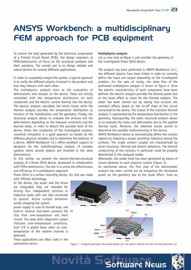
In order to completely analyze the system, a typical approachis to verify the different physics involved in the problem andhow they interact with each other. The multiphysics analysis aims at the evaluation ofdeformations and stresses on the device. These are strictlycorrelated with the temperature distribution on eachcomponent and the electric current flowing into the device.The electric analysis calculates the ohmic losses while thethermal analysis provides the temperature distribution asfunction of the metallization and the geometry. Finally, thestructural analysis allows to evaluate the stresses and thedeformations depending on the imposed constraints and thethermal loads, in order to detach the possible fault of thedevice. Given the complexity of the investigated systems,numerical simulation is a good approach to handle all thedifferent physical variables and to determine the behavior ofa device. ANSYS Workbench 12.1 offers excellent support todesigners for the multidisciplinary analysis of complexsystems where several physics are involved in the samephenomenon.In this article, we present the electro-thermal-structuralanalysis of a Power SO10 device, developed in collaborationwith STMicroelectronics. The aim is to prove the effectivenessand efficiency of a multiphysics approach.Power SO10 is a surface mounting device. Its chip was madewith VIPower technology. In the device, the power and the driverare integrated; they are intended fordriving four independent resistive orinductive loads with one side connectedto ground. Active current limitationavoids dropping the systempower supply in case of shorted load, andbuilt-in thermal shut-down protects thechip from over-temperature and shortcircuit. The open drain diagnostic outputindicates over-temperature conditions.Each I/O is pulled down when an over-temperature of the relative channel isdetected. These applications are often used in theautomotive sector.
Multiphysics analysisLet us now look at figure 1 and consider the geometry ofthe investigated Power SO10 device.
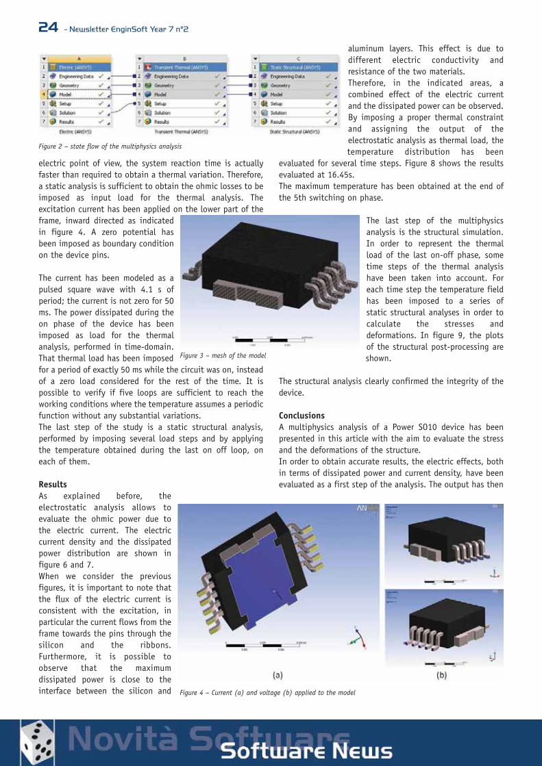
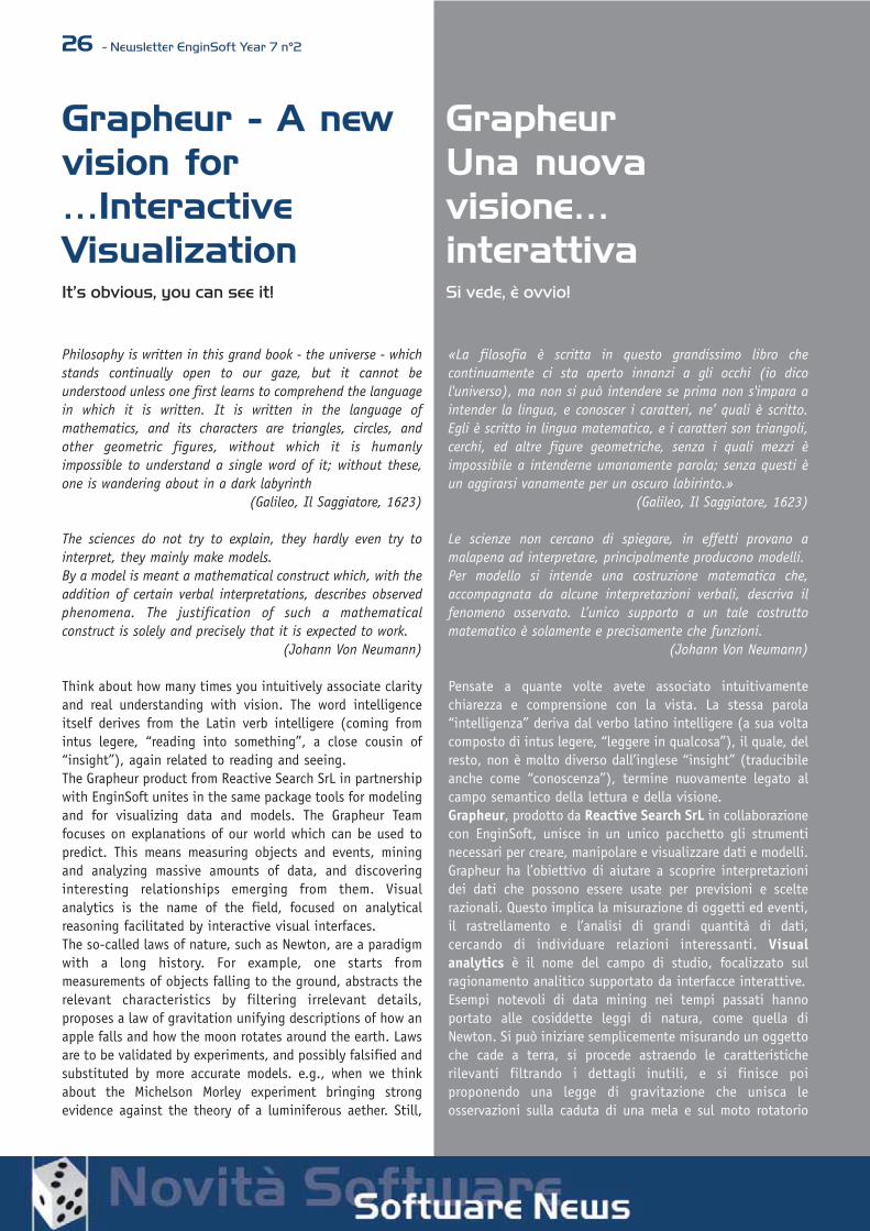
The analysis has been performed in ANSYS Workbench 12.1,the different physics have been linked in order to correctlydefine the input and output depending on the investigatedproblem. For the sake of clarity, the state flow of theperformed multiphysics analysis is shown in figure 2. Oncethe electric characteristics of each component have beendefined, the electric analysis provides the thermal power dueto the Joule effect as input for the thermal analysis. Thelatter has been carried out by taking into account thetransient effects based on the on-off state of the circuitconnected to the device. The output of the transient thermalanalysis is represented by the temperature distribution in thegeometry. Subsequently, the static structural analysis allowsus to evaluate the stress and deformation due to the appliedthermal loads. Moreover, the obtained results permit todetermine the possible malfunctioning of the device.ANSYS Workbench allows to automatically define the contactregions by imposing a proper proximity tolerance among thesurfaces. The single contact couples are characterized bygiven structural, thermal and electric behaviors. The thermalconductivity of the contacts in particular could be properlydetermined in the analyzed model.Afterwards, the model mesh has been generated by means ofclosed elements to each physical contact (Figure 3).As mentioned above, the first step of the electrostaticanalysis has been carried out by evaluating the dissipatedpower on the geometry due to the Joule effect. From an
Figure 1 – Analyzed geometry: the overall system (a), the system without case (b) and the particulars (c)
24 - Newsletter EnginSoft Year 7 n°2
electric point of view, the system reaction time is actuallyfaster than required to obtain a thermal variation. Therefore,a static analysis is sufficient to obtain the ohmic losses to beimposed as input load for the thermal analysis. Theexcitation current has been applied on the lower part of theframe, inward directed as indicatedin figure 4. A zero potential hasbeen imposed as boundary conditionon the device pins.
The current has been modeled as apulsed square wave with 4.1 s ofperiod; the current is not zero for 50ms. The power dissipated during theon phase of the device has beenimposed as load for the thermalanalysis, performed in time-domain.That thermal load has been imposedfor a period of exactly 50 ms while the circuit was on, insteadof a zero load considered for the rest of the time. It ispossible to verify if five loops are sufficient to reach theworking conditions where the temperature assumes a periodicfunction without any substantial variations.The last step of the study is a static structural analysis,performed by imposing several load steps and by applyingthe temperature obtained during the last on off loop, oneach of them.
ResultsAs explained before, theelectrostatic analysis allows toevaluate the ohmic power due tothe electric current. The electriccurrent density and the dissipatedpower distribution are shown infigure 6 and 7.When we consider the previousfigures, it is important to note thatthe flux of the electric current isconsistent with the excitation, inparticular the current flows from theframe towards the pins through thesilicon and the ribbons.Furthermore, it is possible toobserve that the maximumdissipated power is close to theinterface between the silicon and
aluminum layers. This effect is due todifferent electric conductivity andresistance of the two materials.Therefore, in the indicated areas, acombined effect of the electric currentand the dissipated power can be observed.By imposing a proper thermal constraintand assigning the output of theelectrostatic analysis as thermal load, thetemperature distribution has been
evaluated for several time steps. Figure 8 shows the resultsevaluated at 16.45s.The maximum temperature has been obtained at the end ofthe 5th switching on phase.
The last step of the multiphysicsanalysis is the structural simulation.In order to represent the thermalload of the last on-off phase, sometime steps of the thermal analysishave been taken into account. Foreach time step the temperature fieldhas been imposed to a series ofstatic structural analyses in order tocalculate the stresses anddeformations. In figure 9, the plotsof the structural post-processing areshown.
The structural analysis clearly confirmed the integrity of thedevice.
ConclusionsA multiphysics analysis of a Power SO10 device has beenpresented in this article with the aim to evaluate the stressand the deformations of the structure.In order to obtain accurate results, the electric effects, bothin terms of dissipated power and current density, have beenevaluated as a first step of the analysis. The output has then
Figure 2 – state flow of the multiphysics analysis
Figure 3 – mesh of the model
Figure 4 – Current (a) and voltage (b) applied to the model

Newsletter EnginSoft Year 7 n°2 - 25
been applied as input for the subsequent transient thermalanalysis; the obtained temperature distribution depended onthe on-off state of the device. As last step of the study, thestress and deformations have been evaluated by means of astatic structural analysis by imposing the thermal loads.For this and similar applications, ANSYS Workbench 12.1 is ahighly efficient software to perform the multiphysics analysiswhere several phenomena, such as electric, thermal andstructural, are depending on each other.
Future workWith the aim to provide a more exhaustive structural study ofthe device, further analyses will be performed with a focuson:• Non-linear and orthotropic properties of some materials,
such as plastic curves or viscoplastic models.• A thorough study of the contact to take into account the
gluing of the parts; a submodel analysis is suggested forthis purpose. ANSYS Workbench in particular allows toinsert contact properties to assess local detaches.
• a fatigue evaluation.
Dr. Giuseppe Malgioglio - STMicroelectronics srl, ItalyIng. Alice Pellegrini – EnginSoft S.p.A.
Ing. Emiliano D’Alessandro – EnginSoft S.p.A.
For more information:Alice Pellegrini - EnginSoft [email protected]
Figure 5 – electric current density
Figure 6 – dissipated power distribution due to the Joule effects
Figure 7 – temperature distribution at 16.45 s
Figure 8 – total deformation, Von Mises stress and shear stress
26 - Newsletter EnginSoft Year 7 n°2
Grapheur - A newvision for…InteractiveVisualizationIt’s obvious, you can see it!
Philosophy is written in this grand book - the universe - whichstands continually open to our gaze, but it cannot beunderstood unless one first learns to comprehend the languagein which it is written. It is written in the language ofmathematics, and its characters are triangles, circles, andother geometric figures, without which it is humanlyimpossible to understand a single word of it; without these,one is wandering about in a dark labyrinth
(Galileo, Il Saggiatore, 1623)
The sciences do not try to explain, they hardly even try tointerpret, they mainly make models.By a model is meant a mathematical construct which, with theaddition of certain verbal interpretations, describes observedphenomena. The justification of such a mathematicalconstruct is solely and precisely that it is expected to work.
(Johann Von Neumann)
Think about how many times you intuitively associate clarityand real understanding with vision. The word intelligenceitself derives from the Latin verb intelligere (coming fromintus legere, “reading into something”, a close cousin of“insight”), again related to reading and seeing.The Grapheur product from Reactive Search SrL in partnershipwith EnginSoft unites in the same package tools for modelingand for visualizing data and models. The Grapheur Teamfocuses on explanations of our world which can be used topredict. This means measuring objects and events, miningand analyzing massive amounts of data, and discoveringinteresting relationships emerging from them. Visualanalytics is the name of the field, focused on analyticalreasoning facilitated by interactive visual interfaces.The so-called laws of nature, such as Newton, are a paradigmwith a long history. For example, one starts frommeasurements of objects falling to the ground, abstracts therelevant characteristics by filtering irrelevant details,proposes a law of gravitation unifying descriptions of how anapple falls and how the moon rotates around the earth. Lawsare to be validated by experiments, and possibly falsified andsubstituted by more accurate models. e.g., when we thinkabout the Michelson Morley experiment bringing strongevidence against the theory of a luminiferous aether. Still,
GrapheurUna nuovavisione…interattivaSi vede, è ovvio!
«La filosofia è scritta in questo grandissimo libro checontinuamente ci sta aperto innanzi a gli occhi (io dicol'universo), ma non si può intendere se prima non s'impara aintender la lingua, e conoscer i caratteri, ne’ quali è scritto.Egli è scritto in lingua matematica, e i caratteri son triangoli,cerchi, ed altre figure geometriche, senza i quali mezzi èimpossibile a intenderne umanamente parola; senza questi èun aggirarsi vanamente per un oscuro labirinto.»
(Galileo, Il Saggiatore, 1623)
Le scienze non cercano di spiegare, in effetti provano amalapena ad interpretare, principalmente producono modelli.Per modello si intende una costruzione matematica che,accompagnata da alcune interpretazioni verbali, descriva ilfenomeno osservato. L’unico supporto a un tale costruttomatematico è solamente e precisamente che funzioni.
(Johann Von Neumann)
Pensate a quante volte avete associato intuitivamentechiarezza e comprensione con la vista. La stessa parola“intelligenza” deriva dal verbo latino intelligere (a sua voltacomposto di intus legere, “leggere in qualcosa”), il quale, delresto, non è molto diverso dall’inglese “insight” (traducibileanche come “conoscenza”), termine nuovamente legato alcampo semantico della lettura e della visione.Grapheur, prodotto da Reactive Search SrL in collaborazionecon EnginSoft, unisce in un unico pacchetto gli strumentinecessari per creare, manipolare e visualizzare dati e modelli.Grapheur ha l’obiettivo di aiutare a scoprire interpretazionidei dati che possono essere usate per previsioni e scelterazionali. Questo implica la misurazione di oggetti ed eventi,il rastrellamento e l’analisi di grandi quantità di dati,cercando di individuare relazioni interessanti. Visualanalytics è il nome del campo di studio, focalizzato sulragionamento analitico supportato da interfacce interattive.Esempi notevoli di data mining nei tempi passati hannoportato alle cosiddette leggi di natura, come quella diNewton. Si può iniziare semplicemente misurando un oggettoche cade a terra, si procede astraendo le caratteristicherilevanti filtrando i dettagli inutili, e si finisce poiproponendo una legge di gravitazione che unisca leosservazioni sulla caduta di una mela e sul moto rotatorio

Newsletter EnginSoft Year 7 n°2 - 27we are also settling for models which are less clean andprecise than the laws of nature; for instance: empiricalmodels to explain the meaning of relevant documents in theweb, models to predict if a customer would like a movie fromdata collected by other customers, models to cluster entities(e.g.,to cluster a large number of design solutions), identifyprototypes and study them, models to gain insights frommassive data produced by CAE software tools.In addition to modeling and visualizing data or information,Grapheur helps the user to strengthen the power ofabstraction. Without the support to simplify and findcommonalities among superficially different phenomena, oneis easily lost among a sea of details. Vice versa,understanding abstraction means discovering that - inscience and technology - to explain often means: to unify !If you think objectively, the law of gravitation does notexplain why objects are falling (it does not explain the deepphilosophical reasons), it simply explains how they fall,covering an infinite number of cases in an extremely wellsummarized manner. It sounds, and it actually is superficial,not to touch the essence of phenomena, but it is for sureeffective, reproducible and successful.Pragmatically, abstraction and use of basic mathematicaltools is an excellent way to be able to solve challenging newproblems by discovering some abstract resemblance to knowncases. For example, if one understands linear algebra onemay use it to discover new ways of analyzing hugecollections of documents, such as, for example, the web andto create extremely successful and profitable search methods,just as Google did! If one knows basic minimizationtechniques, e.g. steepest descent, one may use it to buildpowerful and flexible machines which learn from examples,such as neural networks with error back-propagation orsimilar machine-learning methods.
An example: Partitioning a mesh for parallel computing in Computational Fluid DynamicsData: Complex physics simulations as common inComputational Fluid Dynamics require huge computational
della Luna attorno alla Terra. Le leggi hanno bisogno diessere sostenute e validate dagli esperimenti, e magariconfutate e sostituite da modelli più accurati (pensiamo alrisultato negativo dell’esperimento di Michelson Morleycontro la teoria dell’etere luminifero). A volte i modelli si rivelano meno semplici e precisi delleleggi di natura. Ad esempio si considerino i modelli empiriciutilizzati per spiegare la rilevanza delle pagine web, quelli di“collaborative recommendation” che tentano di predire se uncliente apprezzerà un prodotto sulla base dei dati raccolti daaltri acquirenti, quelli per aggregare elementi (ad esempiosoluzioni di progettazione), ed individuarne dei prototipi, omodelli per visualizzare soluzioni prodotte da software CAE.Oltre alla visualizzazione ed analisi dei dati e delleinformazioni, Grapheur aiuta l’utente a rafforzare le suecapacità di astrazione. Se non si cercano somiglianze frafenomeni apparentemente simili, è facile perdersi nel maredei dettagli. Spiegare in senso scientifico vuol dire unificare.Se si riflette un attimo, la legge di gravità non spiega perchégli oggetti cadano (non ne sviscera le profonde ragionifilosofiche), tenta semplicemente di illustrare come questioggetti precipitano, coprendo un numero pressoché infinitodi casi attraverso un’ottima sintesi. Sembra, ed in realtà è,una spiegazione superficiale: non tocca l’essenza delfenomeno, ma è sicuramente un metodo efficace,riproducibile e vincente.
Nella pratica, l’astrazione e l’uso degli strumenti matematicidi base costituiscono un modo eccellente per risolvereproblemi nuovi ed impegnativi, trovando somiglianzeastratte all’interno dei casi noti. Per esempio, se sicomprende l’algebra lineare si può utilizzarla per trovarenuovi modi per analizzare grandi gruppi di documenti, adesempio delle pagine web, riuscendo in questo modo atrovare metodi efficaci per effettuare delle ricerche,esattamente come fa Google! Se si conoscono anche letecniche più basilari di ottimizzazione, come la discesa lungoil gradiente, si possono costruire macchine flessibili quantopotenti che possano imparare per esempi, come una rete
Figure 1 - Computational grid for computing airflow over a wing. Flow is leftto the right, the wing is 1.4 degrees from horizontal. The grid is adaptive intwo ways: the size of the triangles controls the spatial resolution of the simu-lation, and the grid is also split into pieces for parallel execution by 32 pro-cessors, so that each gets the same number of triangles. Refinement is basedon the gradient of the pressure, especially at the leading edge (left) and atthe shock. The shock is above the airfoil, 2/3 back. However, there is noshock below the wing: thus the aerodynamics is visible through its effect onthe adaptive grid. Credit: Roy Williams, Geoffrey Fox, California Institute of Technology
Figura 1 - Griglia di calcolo per la valutazione del flusso d’aria, direzionato dasinistra a destra, su un’ala con inclinazione di 1.4° orizzontale. La griglia èadattativa in due direzioni: la grandezza dei triangoli controlla la risoluzionespaziale della simulazione, mentre l’intera superficie è suddivisa in sezioni,rappresentanti le 32 unità computazionali per il calcolo in parallelo, in mododa garantire ad ogni processore lo stesso numero di triangoli. Gli effetti aero-dinamici infatti sono facilmente visibili sulla griglia adattativa.Credito: Roy Williams, Geoffrey Fox, California Institute of Technology

28 - Newsletter EnginSoft Year 7 n°2
resources. Parallel computing can speed up simulation runs.The original space of the simulation is covered by a discretemesh, and the mesh is partitioned into a set of disjointdomains. Each domain is associated to a different computer.The mesh partitioning problem has multiple objectives: oneaims at a well-balanced partition (sub-domains containing asimilar number of nodes) and at a cut of minimum size (thenumber of edges which are cut is proportional to the numberof messages that must flow between different processors, i.e.to the cost of communication).
Objectives of data mining and visualization: 1. To couple visualization with an iterative mesh-
partitioning (graph-partitioning) technique, so that theuser starts with a partition into two domains, and theniteratively splits each domain into two.
2. To visualize the tree of solutions. The root of the treecorresponds to the entire mesh. The children of a nodecorrespond to different ways of splitting each domain ofthe partition corresponding to the parent node.
3. To identify a proper trade-off between balance and cutsize of the partitions.
The navigation mode can visualize the multiple levels of thepartitioning. By starting from the root and by double-clicking on a node, the user can visualize the nodes’ children.By double-clicking on the background, the user visualizes theentire set of solutions. Trade-offs can be studied in theparallel coordinate display or through the scatterplotvisualization feature.
For more information:Many examples in different areas are already available at:http://grapheur.com/info/cases/If you do not find a relevant example for your case, we areready to accept a sample of your data and your wildestvisualization desires! We will get back to you with someexample visualizations, see also our Thomas service(http://grapheur.com/info/thomas/). Special purposevertical applications can also be realized on demand.
We encourage you to download a free evaluation copy fromthe web site www.grapheur.com. Enjoy your navigation!
neurale con retro propagazione dell’errore o metodi simili di“machine-learning”.
Un esempio: Suddividere una mesh per il calcolo paralleloin Computational Fluid DynamicsDati: simulazioni fisiche complesse, ad esempio comuni inComputational Fluid Dynamics, richiedono grandi risorse dielaborazione. Il calcolo parallelo è usato solitamente perridurre il tempo della simulazione: lo spazio originario dellasimulazione è coperto da una mesh discretizzata, suddivisa indomini indipendenti, ognuno associato ad un computerdiverso. Il problema del partizionamento della mesh ha variobiettivi: uno punta alla suddivisione bilanciata della griglia(punta cioè ad avere un numero simile di nodi per dominio),mentre un altro tende a creare confini di dimensioni ridotte(il numero degli archi tagliati è proporzionale alla quantitàdi informazioni che devono fluire fra i vari processori; quindial costo della comunicazione).
Obiettivi delle tecniche di data mining e visualizzazione: • Collegare più visualizzazioni con una tecnica sequenziale
di partizionamento dei grafi per permettere all’utente dipartire con una situazione a due domini e successivamen-te proseguire suddividendo ognuno dei due in due parti.
• Visualizzare le tre soluzioni. La radice dell’albero corri-sponde alla mesh completa. I figli di un nodo corrispon-dono invece a differenti modi di suddividere ogni domi-nio della partizione associata al nodo genitore.
• Identificare un giusto compromesso fra bilanciamentoe lunghezza del taglio delle partizioni.
La modalità “navigazione” può visualiz-zare livelli multipli di partizionamento.Partendo dalla radice e facendo doppio-click su un nodo, l’utente potrà vedere inodi figli relativi. Facendo doppio-clicksullo sfondo, si visualizza invece l’interogruppo di soluzioni. Le soluzioni posso-no essere studiate utilizzando le coordi-nate parallele o tramite la visualizzazio-ne a scatterplot.
Per altre informazioni:Molti esempi in campi differenti sono
già disponibili all’indirizzo: http://grapheur.com/info/cases/Se non trovate un esempio che si adatti al vostro caso d’uso,siamo disponibili a ricevere un campione dei vostri dati ed ivostri più segreti desideri di visualizzazione! Vi risponderemocon alcuni esempi che dimostrano cosa potete fare con ivostri dati: date un’occhiata al nostro servizio “Thomas”(http://grapheur.com/info/thomas/) e ricordate che leapplicazioni verticali possono essere sviluppate al volo, aseconda delle vostre necessità.
Vi consigliamo di scaricare la vostra copia di valutazionegratuita dal nostro sito web www.grapheur.com. Enjoy yournavigation!
Figure 2 - Visualizing a multi-level mesh partitioning method with Grapheur: A mesh covering adomain is partitioned into two (right) and eight (left) parts.
Figura 2 - visualizzazione di un metodo di partizionamento mesh multilivello con Grapheur. Unamesh comprendente un dominio è suddiviso in due (destra) e poi otto (sinistra) parti.

Newsletter EnginSoft Year 7 n°2 - 29
Visualizing a social network of politicians withGrapheur
Una rete sociale di politici visualizzata con Grapheur.
Visualizing the financial performance of companies with Grapheur’s 7d plot
Prestazioni finanziarie di varie aziende con la visualizzazione 7d plot di Grapheur.
Order from chaos: discovering a regular grid after starting from local informa-tion about distances (Grapheur).
Ordine dal caos: come scoprire una griglia regolare partendo da informazionilocali sulle distanze (Grapheur).
Visualizing a constraint-satisfaction methodwith Grapheur
Visualizzazione di un metodo di soddisfazionedi vincoli con Grapheur.
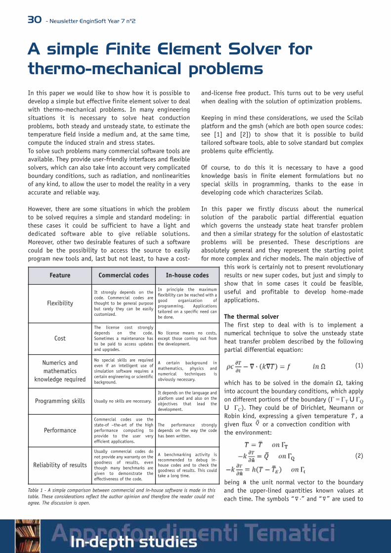
30 - Newsletter EnginSoft Year 7 n°2
A simple Finite Element Solver for thermo-mechanical problemsIn this paper we would like to show how it is possible todevelop a simple but effective finite element solver to dealwith thermo-mechanical problems. In many engineeringsituations it is necessary to solve heat conductionproblems, both steady and unsteady state, to estimate thetemperature field inside a medium and, at the same time,compute the induced strain and stress states.To solve such problems many commercial software tools areavailable. They provide user-friendly interfaces and flexiblesolvers, which can also take into account very complicatedboundary conditions, such as radiation, and nonlinearitiesof any kind, to allow the user to model the reality in a veryaccurate and reliable way.
However, there are some situations in which the problemto be solved requires a simple and standard modeling: inthese cases it could be sufficient to have a light anddedicated software able to give reliable solutions.Moreover, other two desirable features of such a softwarecould be the possibility to access the source to easilyprogram new tools and, last but not least, to have a cost-
and-license free product. This turns out to be very usefulwhen dealing with the solution of optimization problems.
Keeping in mind these considerations, we used the Scilabplatform and the gmsh (which are both open source codes:see [1] and [2]) to show that it is possible to buildtailored software tools, able to solve standard but complexproblems quite efficiently.
Of course, to do this it is necessary to have a goodknowledge basis in finite element formulations but nospecial skills in programming, thanks to the ease indeveloping code which characterizes Scilab.
In this paper we firstly discuss about the numericalsolution of the parabolic partial differential equationwhich governs the unsteady state heat transfer problemand then a similar strategy for the solution of elastostaticproblems will be presented. These descriptions areabsolutely general and they represent the starting pointfor more complex and richer models. The main objective of
this work is certainly not to present revolutionaryresults or new super codes, but just and simply toshow that in some cases it could be feasible,useful and profitable to develop home-madeapplications.
The thermal solverThe first step to deal with is to implement anumerical technique to solve the unsteady stateheat transfer problem described by the followingpartial differential equation:
which has to be solved in the domain Ω, takinginto account the boundary conditions, which applyon different portions of the boundary (Γ = ΓT U ΓQ
U ΓC). They could be of Dirichlet, Neumann orRobin kind, expressing a given temperature , agiven flux or a convection condition withthe environment:
being the unit normal vector to the boundaryand the upper-lined quantities known values ateach time. The symbols “ ” and “ ” are used to
Feature Commercial codes In-house codes
Flexibility
It strongly depends on thecode. Commercial codes arethought to be general purposebut rarely they can be easilycustomized.
In principle the maximumflexibility can be reached with agood organization ofprogramming. Applicationstailored on a specific need canbe done.
Cost
The license cost stronglydepends on the code.Sometimes a maintenance hasto be paid to access updatesand upgrades.
No license means no costs,except those coming out fromthe development.
Numerics andmathematics
knowledge required
No special skills are requiredeven if an intelligent use ofsimulation software requires acertain engineering or scientificbackground.
A certain background inmathematics, physics andnumerical techniques isobviously necessary.
Programming skills Usually no skills are necessary.
It depends on the language andplatform used and also on theobjectives that lead thedevelopment.
Performance
Commercial codes use thestate-of –the-art of the highperformance computing toprovide to the user veryefficient applications.
The performance stronglydepends on the way the codehas been written.
Reliability of results
Usually commercial codes donot provide any warranty on thegoodness of results, eventhough many benchmarks aregiven to demonstrate theeffectiveness of the code.
A benchmarking activity isrecommended to debug in-house codes and to check thegoodness of results. This couldtake a long time.
Table 1 - A simple comparison between commercial and in-house software is made in thistable. These considerations reflect the author opinion and therefore the reader could notagree. The discussion is open.
(1)
(2)
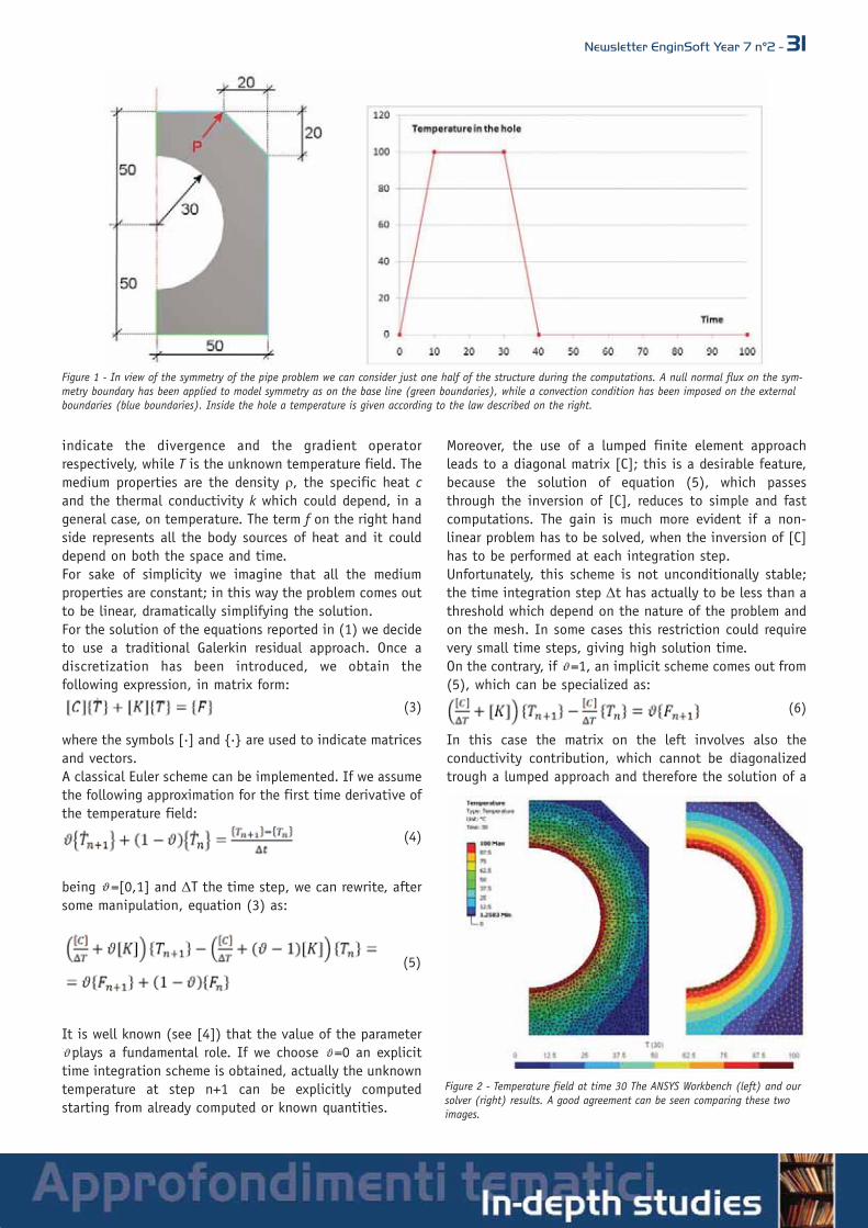
Newsletter EnginSoft Year 7 n°2 - 31
indicate the divergence and the gradient operatorrespectively, while T is the unknown temperature field. Themedium properties are the density ρ, the specific heat cand the thermal conductivity k which could depend, in ageneral case, on temperature. The term f on the right handside represents all the body sources of heat and it coulddepend on both the space and time.For sake of simplicity we imagine that all the mediumproperties are constant; in this way the problem comes outto be linear, dramatically simplifying the solution.For the solution of the equations reported in (1) we decideto use a traditional Galerkin residual approach. Once adiscretization has been introduced, we obtain thefollowing expression, in matrix form:
where the symbols [.] and {.} are used to indicate matricesand vectors.A classical Euler scheme can be implemented. If we assumethe following approximation for the first time derivative ofthe temperature field:
being =[0,1] and ΔT the time step, we can rewrite, aftersome manipulation, equation (3) as:
It is well known (see [4]) that the value of the parameterplays a fundamental role. If we choose =0 an explicit
time integration scheme is obtained, actually the unknowntemperature at step n+1 can be explicitly computedstarting from already computed or known quantities.
Moreover, the use of a lumped finite element approachleads to a diagonal matrix [C]; this is a desirable feature,because the solution of equation (5), which passesthrough the inversion of [C], reduces to simple and fastcomputations. The gain is much more evident if a non-linear problem has to be solved, when the inversion of [C]has to be performed at each integration step.Unfortunately, this scheme is not unconditionally stable;the time integration step Δt has actually to be less than athreshold which depend on the nature of the problem andon the mesh. In some cases this restriction could requirevery small time steps, giving high solution time.On the contrary, if =1, an implicit scheme comes out from(5), which can be specialized as:
In this case the matrix on the left involves also theconductivity contribution, which cannot be diagonalizedtrough a lumped approach and therefore the solution of a
Figure 1 - In view of the symmetry of the pipe problem we can consider just one half of the structure during the computations. A null normal flux on the sym-metry boundary has been applied to model symmetry as on the base line (green boundaries), while a convection condition has been imposed on the externalboundaries (blue boundaries). Inside the hole a temperature is given according to the law described on the right.
Figure 2 - Temperature field at time 30 The ANSYS Workbench (left) and oursolver (right) results. A good agreement can be seen comparing these twoimages.
(3)
(4)
(5)
(6)

32 - Newsletter EnginSoft Year 7 n°2
system of linear equations has to be computed at eachstep. The system matrix is however symmetric and positivedefinite, so a Choleski decomposition can be computedonce for all and at each integration step the backwardprocess, which is the less expensive from a computationalpoint of view, can be performed.This scheme has the great advantage to be unconditionallystable: this means that there are no restriction on the timestep to adopt. Obviously, the larger the step, the larger theerrors due to the time discretization introduced in themodel, according to (4).In principle all the intermediate values for are possible,considering that the stability of the Euler scheme isguaranteed for > 1⁄2,but usually the mostused version are the fullexplicit or implicit one.
In order to test thegoodness of ourapplication we haveperformed many testsand comparisons. Herewe present the simpleexample shown in Figure1. Let us imagine that ina long circular pipe afluid flows with atemperature whichchanges with timeaccording to the lawdrawn in Figure 1, on theright. We want to estimate the temperature distribution atdifferent time steps inside the medium and compute thetemperature of the point P.It is interesting to note that for this simple problem all theboundary conditions described in (2) have to be used. Aunit density and specific heat for the medium has beentaken, while a thermal conductivity of 5 has been chosenfor this benchmark. The environmental temperature hasbeen set to 0 and the convection coefficient to 5.
As shown in the following pictures there is a goodagreement between the results obtained with ANSYSWorkbench and our solver.
The structural solverIf we want to solve a thermo-structural problem (see [3]and references reported therein) we obviously need asolver able to deal with the elasticity equations. We focuson the simplest case, that is two dimensional problems(plane strain, plane stress and axi-symmetric problems)with a completely linear, elastic and isotropic response. Wehave to take into account that a temperature field inducesthermal deformations inside a solid medium. Actually:
where the double index i indicates that no sheardeformation can appear. The TREF represents the referencetemperature at which no deformation is produced insidethe medium.Once the temperature field is known at each time step, itis possible to compute the induced deformations and thenthe stress state.For sake of simplicity we imagine that the loads acting onthe structure are not able to produce dynamic effects andtherefore, if we neglect the body forces contributions, theequilibrium equations reduce to:
or, with the indicial notation
The elastic deformation ε can be computed as thedifference between the total and the thermal contributionsas:
which can be expressed in terms of the displacementvector field u as:
or, with the indicial notation
A linear constitutive law for the medium can be adoptedand written as:
where the matrix D will be expressed in terms of μ and λwhich describe the elastic response of the medium. Finally,after some manipulation involving equations (9), (10) and(11), one can obtain the following governing equation,which is expressed in terms of the displacements field uonly:
As usual, the above equation has to be solved togetherwith the boundary conditions, which typically are ofDirichlet (imposed displacements on Γu) or Neumannkind (imposed tractions on Γp):
Figure 3 - Temperature field in the point P plotted versus time. The ANSYSWorkbench (red) and our solver (blue) results. Also in this case a goodagreement between results is achieved.
Figure 4 - The holed plate under tensionconsidered in this work. We have takenadvantage from the symmetry withrespect to x and y axes to model only aquarter of the whole plate. Appropriateboundary conditions have been adopted,as highlighted in blue.
(7)
(8)
(9)
(10)
(11)
(12)
(13)
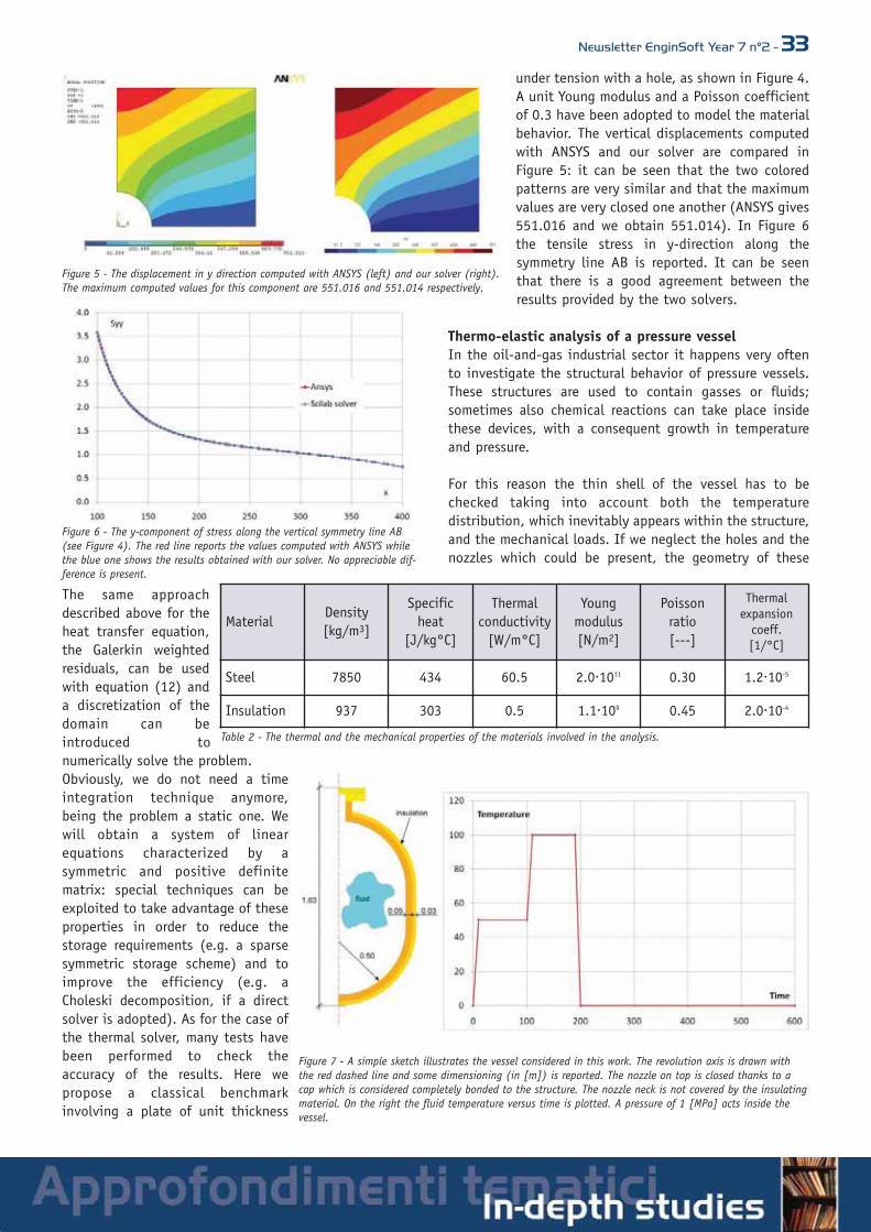
Newsletter EnginSoft Year 7 n°2 - 33
The same approachdescribed above for theheat transfer equation,the Galerkin weightedresiduals, can be usedwith equation (12) anda discretization of thedomain can beintroduced tonumerically solve the problem.Obviously, we do not need a timeintegration technique anymore,being the problem a static one. Wewill obtain a system of linearequations characterized by asymmetric and positive definitematrix: special techniques can beexploited to take advantage of theseproperties in order to reduce thestorage requirements (e.g. a sparsesymmetric storage scheme) and toimprove the efficiency (e.g. aCholeski decomposition, if a directsolver is adopted). As for the case ofthe thermal solver, many tests havebeen performed to check theaccuracy of the results. Here wepropose a classical benchmarkinvolving a plate of unit thickness
under tension with a hole, as shown in Figure 4.A unit Young modulus and a Poisson coefficientof 0.3 have been adopted to model the materialbehavior. The vertical displacements computedwith ANSYS and our solver are compared inFigure 5: it can be seen that the two coloredpatterns are very similar and that the maximumvalues are very closed one another (ANSYS gives551.016 and we obtain 551.014). In Figure 6the tensile stress in y-direction along thesymmetry line AB is reported. It can be seenthat there is a good agreement between theresults provided by the two solvers.
Thermo-elastic analysis of a pressure vesselIn the oil-and-gas industrial sector it happens very oftento investigate the structural behavior of pressure vessels.These structures are used to contain gasses or fluids;sometimes also chemical reactions can take place insidethese devices, with a consequent growth in temperatureand pressure.
For this reason the thin shell of the vessel has to bechecked taking into account both the temperaturedistribution, which inevitably appears within the structure,and the mechanical loads. If we neglect the holes and thenozzles which could be present, the geometry of these
Figure 5 - The displacement in y direction computed with ANSYS (left) and our solver (right).The maximum computed values for this component are 551.016 and 551.014 respectively.
Figure 6 - The y-component of stress along the vertical symmetry line AB(see Figure 4). The red line reports the values computed with ANSYS whilethe blue one shows the results obtained with our solver. No appreciable dif-ference is present.
Figure 7 - A simple sketch illustrates the vessel considered in this work. The revolution axis is drawn withthe red dashed line and some dimensioning (in [m]) is reported. The nozzle on top is closed thanks to acap which is considered completely bonded to the structure. The nozzle neck is not covered by the insulatingmaterial. On the right the fluid temperature versus time is plotted. A pressure of 1 [MPa] acts inside thevessel.
MaterialDensity [kg/m3]
Specificheat
[J/kg°C]
Thermalconductivity
[W/m°C]
Youngmodulus[N/m2]
Poissonratio[---]
Thermalexpansion
coeff.[1/°C]
Steel 7850 434 60.5 2.0.1011 0.30 1.2.10-5
Insulation 937 303 0.5 1.1.109 0.45 2.0.10-4
Table 2 - The thermal and the mechanical properties of the materials involved in the analysis.
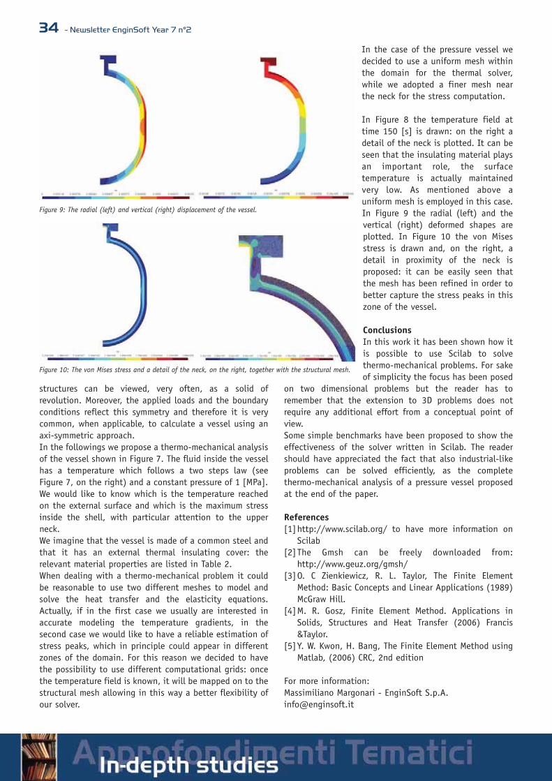
34 - Newsletter EnginSoft Year 7 n°2
structures can be viewed, very often, as a solid ofrevolution. Moreover, the applied loads and the boundaryconditions reflect this symmetry and therefore it is verycommon, when applicable, to calculate a vessel using anaxi-symmetric approach.In the followings we propose a thermo-mechanical analysisof the vessel shown in Figure 7. The fluid inside the vesselhas a temperature which follows a two steps law (seeFigure 7, on the right) and a constant pressure of 1 [MPa].We would like to know which is the temperature reachedon the external surface and which is the maximum stressinside the shell, with particular attention to the upperneck.We imagine that the vessel is made of a common steel andthat it has an external thermal insulating cover: therelevant material properties are listed in Table 2.When dealing with a thermo-mechanical problem it couldbe reasonable to use two different meshes to model andsolve the heat transfer and the elasticity equations.Actually, if in the first case we usually are interested inaccurate modeling the temperature gradients, in thesecond case we would like to have a reliable estimation ofstress peaks, which in principle could appear in differentzones of the domain. For this reason we decided to havethe possibility to use different computational grids: oncethe temperature field is known, it will be mapped on to thestructural mesh allowing in this way a better flexibility ofour solver.
In the case of the pressure vessel wedecided to use a uniform mesh withinthe domain for the thermal solver,while we adopted a finer mesh nearthe neck for the stress computation.
In Figure 8 the temperature field attime 150 [s] is drawn: on the right adetail of the neck is plotted. It can beseen that the insulating material playsan important role, the surfacetemperature is actually maintainedvery low. As mentioned above auniform mesh is employed in this case.In Figure 9 the radial (left) and thevertical (right) deformed shapes areplotted. In Figure 10 the von Misesstress is drawn and, on the right, adetail in proximity of the neck isproposed: it can be easily seen thatthe mesh has been refined in order tobetter capture the stress peaks in thiszone of the vessel.
ConclusionsIn this work it has been shown how itis possible to use Scilab to solvethermo-mechanical problems. For sakeof simplicity the focus has been posed
on two dimensional problems but the reader has toremember that the extension to 3D problems does notrequire any additional effort from a conceptual point ofview.Some simple benchmarks have been proposed to show theeffectiveness of the solver written in Scilab. The readershould have appreciated the fact that also industrial-likeproblems can be solved efficiently, as the completethermo-mechanical analysis of a pressure vessel proposedat the end of the paper.
References[1]http://www.scilab.org/ to have more information on
Scilab[2]The Gmsh can be freely downloaded from:
http://www.geuz.org/gmsh/[3]O. C Zienkiewicz, R. L. Taylor, The Finite Element
Method: Basic Concepts and Linear Applications (1989)McGraw Hill.
[4]M. R. Gosz, Finite Element Method. Applications inSolids, Structures and Heat Transfer (2006) Francis&Taylor.
[5]Y. W. Kwon, H. Bang, The Finite Element Method usingMatlab, (2006) CRC, 2nd edition
For more information:Massimiliano Margonari - EnginSoft [email protected]
Figure 9: The radial (left) and vertical (right) displacement of the vessel.
Figure 10: The von Mises stress and a detail of the neck, on the right, together with the structural mesh.

Newsletter EnginSoft Year 7 n°2 - 35
EnginSoft intervista l’ing.Franzoni diSuperjetInternational
SuperJet International nasce nel 2007 come risul-tato della prima collaborazione strutturale in cam-po aeronautico tra un’azienda occidentale, AleniaAeronautica, ed una russa, Sukhoi Holding, nelcampo dell’aviazione commerciale.L’obiettivo è quello di commercializzare nel mondooccidentale, predisporre e realizzare le configura-zioni Cliente e fornire supporto logistico globale alnuovo Sukhoi Superjet 100, velivolo regionale a
getto da 100 posti di nuova generazione, attualmente in fa-se di prove di sviluppo e certificazione con i suoi 4 prototi-pi e atteso all’entrata in servizio entro il 2010. La società è basata a Venezia.L’ing. Alessandro Franzoni, 22 anni in Alenia Aeronautica, èdall’inizio di questa impresa l’Amministratore Delegato diSuperJet International, dopo aver ricoperto per 3 anni ilruolo di Chief Technical Officer in Alenia Aeronautica.
1. Che spazio ha (e dovrebbe avere) l’innovazione nelmondo industriale/impresariale?È ormai riconosciuto in tutti i settori che l’innovazione haun ruolo primario: le aziende che dimostrano la maggior ca-pacità di innovare risultano quelle di maggior successo.Questo vale anche nel settore aeronautico. Piuttosto è inte-ressante definire l’ambito dell’innovazione nel campo dellenostre attività: è certamente riduttivo vedere l’innovazionelimitata alle tecnologie per la realizzazione di nuovi prodot-ti, occorre considerare anche l’insieme dei processi, sia quel-li di sviluppo, produzione e supporto ma anche quelli dimanagement. La struttura delle collaborazioni in campo ae-ronautico sta rapidamente evolvendo da rapportiCliente/Fornitore o Prime/Sub a quella delle cosiddette
EnginSoftinterviewsAlessandroFranzoni, CEO ofSuperjetInternationalSuperjet International was established in 2007 as apowerful “joint-venture” between AleniaAeronautica, a West European organization, andSukhoi Holding, a Russian-based company. Fromthe beginning, the partnership has been based ona well-structured joint initiative in the aeronauticfield.The primary objective is to market the new SukhoiSuperjet 100, a shortrange aircraft (100 seats).Today, its 4 prototypes are actually in the development andcertification stage; the aircraft is expected to be in regularoperation in the second half of 2010.Superjet International is based at Venice’s Marco PoloInternational Airport.Roberto Gonella of EnginSoft had the pleasure to interviewAlessandro Franzoni, a veteran of 22 years in AleniaAeronautica. Since its foundation, Mr Franzoni has been theCEO of Superjet International. Prior to that, he supportedAlenia Aeronautica where he hold the position of ChiefTechnical Officer for 3 years.
1. Which is the role (or should be the role) of innovationin the industrial and entrepreneurial world?Innovation has a primary role in all industrial and non-industrial sectors: the most successful companies are alwaysthe ones whose first ambition is to innovate their product.This can also be clearly observed in the aeronautical sector.It is extremely important to define the sphere of innovationin our typical application areas: for example, it is notsufficient to base our technology innovation on new productmanufacturing; instead, it is essential to include alldevelopment, production, support and managementprocesses in our innovation endeavors.The historical actors in the aeronautical fields (the clientand its supplier) are emerging from their ancient and well-structured relationship to become new global companies, so-called global extended enterprises. This way, client,partnership and supplier are establishing a new “complete”company on a worldwide scale.In our environment, guidelines for a new aircraft arechanging, evolving with time. We would not succeed if weconsider multi-disciplinary integration only in the single

36 - Newsletter EnginSoft Year 7 n°2
“Global Extended Enterprises”, cioèaziende “estese”, che includono Clienti,partners e fornitori su scala mondiale.Su questi temi altri settori industriali cihanno preceduto, basti pensare all’automotive. Ma è già cambiato ilmodo di progettare i nuovi velivoli. Inquesto senso oggi parlare di integra-zione multidisciplinare non più e nonsolo all’interno della singola aziendama nell’azienda globale estesa, utiliz-
zando i più avanzati sistemi di simulazione real time, con-sente veramente di operare praticamente senza soluzione dicontinuità nelle 24 ore. L’integrazione tra fornitore e cliente finale ha raggiunto li-velli molto alti ed oggi, parlando nello specifico del settoredi cui mi occupo, gli aerei regionali, la nostra performanceè determinante per i risultati dei nostri Clienti, le compagnieaeree, ed anche il modo con cui ci si rapporta è cambiatomoltissimo: una delle innovazioni principali nella strutturadel business, il supporto logistico “Power by the Hour”, fu ilrisultato di un problema di costi e flessibilità operativa del-le aerolinee interpretato in chiave innovativa da un fornito-re di motori… Per quanto riguarda i prodotti si registra sempre di più unacontaminazione tra tecnologie ed innovazioni provenienti daaltri settori (pensiamo come le più avanzate tecnologie dicomunicazione hanno cambiato e stanno cambiando non so-lo le prestazioni degli aerei commerciali ma anche la fruizio-ne del mezzo aereo che ognuno di noi sperimenta giornal-mente, con la possibilità ormai disponibile di fare tranquil-lamente acquisti on line durante il volo e magari trovare lamerce acquistata all’aeroporto di arrivo…). Del resto le tecnologie chiave del futuro sono quelle checonsentiranno di integrare più funzionalità all’interno di sin-gole strutture o sistemi, le strutture funzionalizzate attra-verso l’utilizzo di nano materiali consentiranno di aumenta-re le prestazioni, ridurre i pesi e aumentare la vita degli ae-rei futuri. E le nanotecnologie sono un esempio eccellente dicross-industry.Quello che raccomando sempre a chi lavora con me è di ave-re curiosità per quello che avviene in settori contigui al no-stro, il maggior contenuto di innovazione per il futuro dellanostra industria verrà probabilmente da settori non aeronau-tici.
2. Quali sono le strategie per essere innovativi e quali va-lutazioni spingono all’innovazione?La spinta all’innovazione viene dalla necessità di crescere. Siè costretti ad innovare. Per saper innovare occorrono moltecondizioni. Una condizione essenziale è conoscere il propriobusiness ma soprattutto anticiparne i cambiamenti. Per que-sto occorre avere molti sensori: i principali sono i Clienti, maspesso i Clienti tendono ad essere conservatori, almeno finoa quando non incontrano grossi problemi che allora cercanodi ribaltare sui fornitori! Occorre saper imparare, occorre ge-stire e condividere la conoscenza.
company. It clearly needs the new global company tooperate 24 hours a day without interruption using the mostadvanced simulation systems for our product developmentand manufacturing.The new dynamic rules between the client and his provideralso require a high level management relationship. In mybusiness and logistics support groups, “Power by the Hour”delivers daily positive results based on flexibility and costsolutions. We have achieved our goals by using the “newdeal” for engine providers.The positive impact of innovation and technology onconsumer products, can be witnessed also in our daily lives;for example: we can buy goods on-line during a flight andpick them up upon our arrival at the destination airport.A clear example of the positive impact of differenttechnologies in the aeronautical field, is the capability ofsynthesizing more functionalities into a single structure. Thewide use of advanced nanomaterial technologies will allowto increase performances, reduce weight and to lengthen thelife of our future aircrafts; in other words, nanotechnologyis an excellent example of cross-sectoral activities inindustry.Finally, I always encourage my co-workers to be more curiousabout the events in sectors close to ours. In my opinion themost innovative contents for the future of our industry willprobably come from non-aeronautical sectors.
2. Which are the strategies for innovation and whatpushes them forward?Innovation is pushed forward by growing demands, we areforced to innovate our product while a series of boundaryconditions has to be met.First of all, business knowledge is essential, and we have tobe able to predict changes in our business. Our business sensitivity should be activated by varioussensors: our client, its attitude and demands. Quite oftenthough, the client is inclined to be conservative, at leastuntil he/she unfortunately faces challenging technicalproblems. Then, their policy naturally is to hand over theproblem to their supplier.I strongly believe that we have to learn our lessons,exchange and share our knowledge. We have to be curious,versatile, look at other sectors, other businesses: somebodyonce said: to innovate means to copy in a better way… butfirst of all, innovation should be about motivation. People,their enthusiasm, their believes, their excitement about

Newsletter EnginSoft Year 7 n°2 - 37Occorre avere curiosità e tra-sversalità, guardare altri setto-ri, altri business: c’è chi diceche innovare significa copiareal meglio… Ma l’innovazione va anzituttostimolata. Le persone, il loroentusiasmo, il credere e la pas-sione nel loro lavoro sono es-senziali per l’innovazione: oc-corre perciò lavorare per crea-re le premesse per un ambien-te creativo. E ricordiamoci che
innovazione è diverso da tecnologia: si può essere grandi in-novatori anche senza “inventare” tecnologie, ma anticipan-do o addirittura creando dei bisogni o delle aspettative, co-me insegnano Apple e alcuni altri…
3. Che ruolo ricoprono gli strumenti CAE e di prototipazio-ne virtuale in tal senso? Sono sia dei facilitatori che degli stimolatori.Laddove la riduzione del time to market (attraverso il supe-ramento di quella fase intermedia tra sviluppo e produzioneche è la cosiddetta industrializzazione) e la riduzione dei co-sti di sviluppo rappresentano obiettivi primari nel nostrosettore, tutto ciò che favorisce l’integrazione multidiscipli-nare e la capacità di sviluppare velocemente trade offs diconfigurazione riduce tempi e costi.D’altra parte abituando e in qualche modo costringendo adapprocciare i fenomeni in modo multidisciplinare, “paralle-lo” e non “sequenziale”, si migliorano le capacità di intera-zione e di ottimizzazione delle soluzioni e si migliora il pro-dotto.
4. Come sono cambiate le esigenze degli utilizzatori negliultimi anni?Il principale fattore di cambiamento sta nell’esigenza di rea-lizzare una vera integrazione multidisciplinare e di operarespesso in real time.
5. Quali vantaggi ha rilevato nella sua esperienza profes-sionale e come è cambiato il suo approccio alla progetta-zione/produzione?Il cambiamento maggiore sta nell’aver riconosciuto che an-che nelle attività di ricerca e sviluppo la forza sta nel net-work e nell’approccio collaborativo. La difesa e la protezio-
their work and future areessential for innovation: themanager should be able toset the conditions for acreative workingenvironment.Remember that innovation isquite different fromtechnology: you can be agreat innovator withoutdeveloping any technology,but predicting or evencreating generalrequirements or expectations, like Apple and other providersteach us.
3. Which are the roles of CAE and Virtual Prototyping?These are strong instruments with two different aims: first,to make our daily work easier and, on the other hand, tostimulate our technical ideas and understanding.Time to market and cost reductions are the main reasons forapplying CAE and VP in our sector. Multidisciplinaryintegration and speed development capabilities deliverexcellent responses for economic optimization because manytrade-off configurations are able to reduce time and cost.In other words, it is better to approach the global technicalproblem in a parallel way rather than in a sequential oneand, if you work in a multidisciplinary way, the technicalphilosophy is right.
4. How did the user’s demand change in the last year?Now, the user’s demand is to realize multidisciplinaryintegration and often, to work in real time.
5. What are the benefits that you have experienced andhow has your work changed in the design and productiondomains?The most important factor is to cultivate our network and toorganize collaborative design methodologies. The defense ofcompany knowledge is gradually substituted by an attitudeof developing and sharing the same know-how with eachother. It really is a cultural jump which should be supportedby effective tools, and these tools should be integrated forthe handling of information: Product Life Cycle Management,and also for multidisciplinary integration and virtualprototyping.
6. In what way has EnginSoft contributed to increase thevalue, the quality and the capabilities of your company?I have always appreciated EnginSoft because of itscapabilities to provide effective and convincing solutions;for example Multi-disciplinary Optimization Software -modeFRONTIER - developed by ESTECO EnginSoft Tecnologieper l’Ottimizzazione and it is widely used in aerospacecompanies.Clearly, companies are looking for partners that are able to
provide added value and not for providers that are only

38 - Newsletter EnginSoft Year 7 n°2
ne del know how hanno lasciato, o stanno lasciando, il po-sto alla condivisione e allo sviluppo del know how. È un sal-to culturale enorme, e soprattutto deve essere sostenuto dastrumenti efficaci ed integrati per la gestione delle informa-zione (Product Life Cycle Management), per l’integrazionemultidisciplinare ed il Virtual Prototyping.
6. Qual è stato il contributo di EnginSoft e in che modo hasaputo valorizzare qualità, potenzialità e capacità dellasua industria/impresa?Quello che ho sempre apprezzato di EnginSoft è la capacitàdi fornire soluzioni, per esempio il software modeFRONTIERper l’ottimizzazione multi-discliplinare, sviluppato daESTECO EnginSoft Tecnologie per l’Ottimizzazione, ampia-mente utilizzato dalle aziende aeronautiche.Oggi le aziende cercano partners che possano portare valoreaggiunto, non fornitori che vendano prodotti.Questo d’altro canto impone una perfetta conoscenza deiprodotti offerti ma anche dei processi di progettazione e svi-luppo del Cliente, per consentire di proporsi come solutori diun problema, spesso mutuando esperienze già fatte in ambi-ti e settori contigui.
7. Che prospettive intravede per i codici di calcolo in rela-zione alle sfide poste dal futuro?Vedo una prospettiva importante, senza dubbio, pensandoanche al fatto che sempre più dovremo ricorrere a soluzionistandardizzate ed integrate in ambienti di simulazione mul-tidisciplinare, e solo per casi “ai limiti” ricorrere a codiciproprietari.Vedo anche, con il futuro delle nanotecnologie e delle strut-ture funzionalizzate, un legame sempre più stretto tra la chi-mica e la fisica su tutta la filiera, dalla progettazione delmateriale alla progettazione del componente.
8. Quali progetti, obiettivi e nuovi traguardi intende per-seguire grazie all’uso di questi strumenti?Oltre ai consueti obiettivi di riduzione dei tempi di svilup-po, dei costi e alla ottimizzazione del prodotto penso chequesti strumenti aumenteranno sempre di più la capacità dinetworking e di collaborazione. Questo è già oggi ma lo sa-rà sempre più in futuro un fattore chiave di successo.
9. E cosa si auspica per il mondo della tecnologia scienti-fica alla continua ricerca di una dimensione tra creativitàe competitività?
Le due dimensioni non solo non competono ma so-no estremamente interconnesse.Competitività vuol sempre più dire capacità di in-novare e di valorizzare l’innovazione. E l’innovazio-ne si sviluppa al meglio in ambienti creativi. Ilcreativo non è il genialoide anarchico, è il profes-sionista inserito nel processo aziendale che con lasua capacità di avere un punto di vista differente,basato sulla sua competenza ed esperienza ma an-che sulla sua abilità di dare risposte non conven-zionali, risolve i problemi e fornisce soluzioni.
selling products. At the same time, a perfect knowledge ofthe recommended products and their abilities, as well as anunderstanding of the entire development and design cyclesare fundamental. For this reason, EnginSoft is a valuedpartner because its experts have the experience to offereffective solutions for different problems. Often, theexpertise of EnginSoft suits our expectations perfectlybecause it can be transferred and adjusted also to sectorsclose to ours.
7. In your opinion, what are the perspectives forcomputational codes in view of the future marketchallenges?In my opinion, calculation codes will play an important role.I’m convinced that in the future, standardized solutions andmultidisciplinary environments will be required and that in-house codes will only be necessary and applied in a handfulof situations.Given the expected development of nanotechnology in thefuture, its functionalities, and the narrow ties betweenchemical and physical requirements, I hope to have thesupport from a computational code which is able to follow aglobal design, all the way from material requirements to thefinal component design.
8. What are the projects that you plan to realize for whichthese tolls will be used?Cost reduction, time to market and product optimization willbe the primary objectives that we hope to reach with thesupport of CAE and VP tools. However, I also plan to increaseour networking capability with the same technologies.
9. What are your expectations for technology developersand vendors who still strive for the right balance betweencompetition and creativity?I believe a creative person shouldnot act as an anarchic inventor.We professionals are importantparts of company processes. Wehave to have the capability todevelop a different point of viewbased on our competencies andexperiences, and to answer tounconventional problems, in otherwords: to solve problems andprovide solutions!

Newsletter EnginSoft Year 7 n°2 - 39
Il Progetto VERDI: Virtual Engineering for RobustManufacturing with Design Integration
La sigla VERDI è l’acronimo di Virtual Engineering for RobustManufacturing with Design Integration ed è il nome di unoprogetto STREP co-finanziato dalla Comunità Europea che siè da poco concluso dopo 4 anni di lavoro. Il progetto è sta-to finalizzato alla creazione e validazione di una metodologiaaffidabile per la simulazio-ne numerica della DesignChain che governa la pro-gettazione di componentiaeronautici.La progettazione di talicomponenti ha la preroga-tiva di coinvolgere un ele-vato numero di aziendecon competenze e utilizza-zione di strumenti, siasoftware che hardware ete-rogenei che rendono il flus-so delle attività particolar-mente complesso.Il progetto ha inoltre svi-luppato protocolli per vali-dare in modo verticale ognifase della Design Chain,validando ogni lavorazionevirtuale con risultati rica-vati da test sperimentali(es. caratterizzazione deimateriali).
Dal punto di vista della simula-zione numerica, particolare im-portanza è stata ricoperta dallacapacità di trasmettere i risul-tati tra software diversi, che possono utilizzare mesh anchemolto dissimili, senza perdere dati significativi, sia tra unafase della Design Chain e la successiva, sia, all’interno di unastessa fase, tra simulazioni effettuate su scale fisichediverse.
Oltre a EnginSoft, il progetto ha coinvolto sei tra i maggioriproduttori europei di motori aeronautici e componentistica(Volvo Aero, Rolls-royce, MTU Aeroengines, Avio, TechspaceAero, ITP), sei Università europee (Aachen University ofTechnology, Karlsruhe, Lulea University of Technology,Trollhattan/Uddevalla University, Notthingam ed ilPolitecnico di Torino), tre centri di ricerca (CIMNE, CENEARO, AIC).
Figura 1 – Virtual – Design – Manufacturing Design Chain.
Figura 2 - Processo di lavorazione e simulazione del componente in Nickel.
Figura 3 - Processo di lavorazione e simulazione del componente in Titanio.

40 - Newsletter EnginSoft Year 7 n°2
Descrizione del lavoro svoltoI partner sono stati divisi in due gruppi che hanno sviluppa-to, in modo indipendente, due sotto componenti sia dal pun-to di vista numerico che nella produzione del prototipo rea-le: una struttura della parte posteriore del motore realizzatain Inconel 718 (lega di Nickel) e una della parte frontale rea-lizzata in Ti-6V-4Al (lega di Titanio).Ogni partner ha utilizzato, come anticipato, un differentesoftware di simulazione, sia per descrivere le diverse fisichecoinvolte, che per descrivere la scala del problema (microscala o macro scala). I dati tra i vari partner sono stati scam-biati mediante software sviluppati all’interno del progetto dadiversi partern.Nella figura 4 è stato riportato, come esempio, la DesignChain virtuale relativa la componente in Nickel.I principali argomenti sviluppati durante il progetto, oltre aquello relativo alla mappatura dei risul-tati, hanno riguardato le simulazioni deiprocessi di deposizione di materiale(metal deposistion), pallinatura (shotpeening), trattamenti termici (heat tre-atment), saldatura (welding), pelo rul-latura (roller burnishing) e lavorazioniper asportazione di truciolo (machi-ning).In particolare, ANSYS è stato utilizzatoin alcune fasi cruciali della catena, qua-li la simulazione della saldatura, dellelavorazioni per asportazioni di truciolo edella valutazione della vita a fatica delcomponente, sfruttandone a pieno lecaratteristiche multi fisiche legate alleanalisi termo-strutturali in accoppia-mento forte.
Contributo di EnginSoftEnginSoft si è occupata della simulazio-ne del processo macroscopico di lavora-zione per asportazione di truciolo delcomponente in Nickel.
La simulazione ha tenuto conto di due effetti che si svilup-pano su scale differenti:1. Un effetto macroscopico legato all’asportazione di una
parte di materiale che va ad alterare lo stato di sforzoauto-equilibrato derivante dalla catena di lavorazione cheprecede la fresatura.
2. Un effetto microscopico dovuto invece alle distorsioniderivanti dagli effetti termo-meccanici che si sviluppanoin un volume molto limitato sotto la superficie esternadel pezzo durante e dopo il passaggio dell’utensile.
Il primo effetto è stato simulato in ANSYS Workbench 11.0mediante l’utilizzo della proprietà degli elementi di ANSYS diessere attivati (Birth) e disattivati (Death) durante una si-mulazione.
Come mostrato in Figura 6, lo stato di solleci-tazione auto-equilibrato mappato dalla simula-zione di pallinatura, è stato alterato disatti-vando gli elementi che devono essere fresati.Il nuovo stato di sforzo, non auto equilibratoha generato una nuova configurazione defor-mata del sotto componente nella nuova confi-gurazione di equilibrio.
Figura 4 - Catena di lavorazione virtuale del sotto componente in Nickel.
Figura 5 – Fresatura sul pezzo reale.
Figura 6 - Effetto della disattivazione degli elementi.
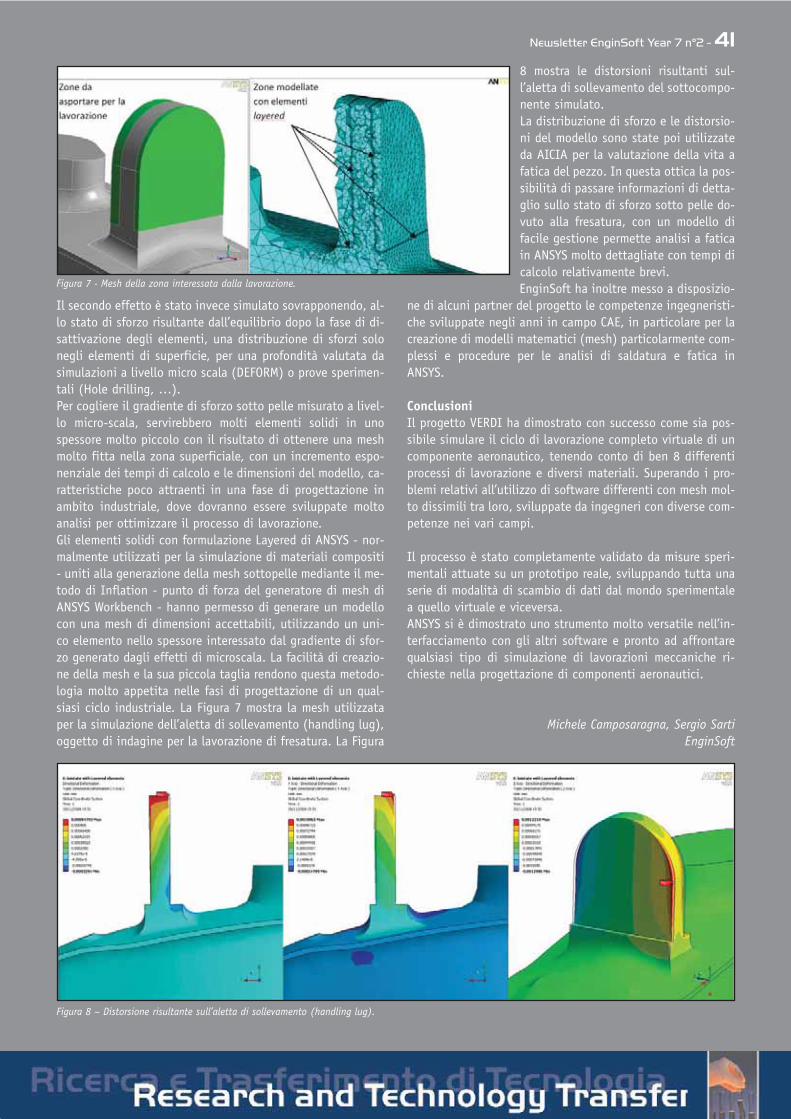
Newsletter EnginSoft Year 7 n°2 - 41
Il secondo effetto è stato invece simulato sovrapponendo, al-lo stato di sforzo risultante dall’equilibrio dopo la fase di di-sattivazione degli elementi, una distribuzione di sforzi solonegli elementi di superficie, per una profondità valutata dasimulazioni a livello micro scala (DEFORM) o prove sperimen-tali (Hole drilling, …).Per cogliere il gradiente di sforzo sotto pelle misurato a livel-lo micro-scala, servirebbero molti elementi solidi in unospessore molto piccolo con il risultato di ottenere una meshmolto fitta nella zona superficiale, con un incremento espo-nenziale dei tempi di calcolo e le dimensioni del modello, ca-ratteristiche poco attraenti in una fase di progettazione inambito industriale, dove dovranno essere sviluppate moltoanalisi per ottimizzare il processo di lavorazione.Gli elementi solidi con formulazione Layered di ANSYS - nor-malmente utilizzati per la simulazione di materiali compositi- uniti alla generazione della mesh sottopelle mediante il me-todo di Inflation - punto di forza del generatore di mesh diANSYS Workbench - hanno permesso di generare un modellocon una mesh di dimensioni accettabili, utilizzando un uni-co elemento nello spessore interessato dal gradiente di sfor-zo generato dagli effetti di microscala. La facilità di creazio-ne della mesh e la sua piccola taglia rendono questa metodo-logia molto appetita nelle fasi di progettazione di un qual-siasi ciclo industriale. La Figura 7 mostra la mesh utilizzataper la simulazione dell’aletta di sollevamento (handling lug),oggetto di indagine per la lavorazione di fresatura. La Figura
8 mostra le distorsioni risultanti sul-l’aletta di sollevamento del sottocompo-nente simulato.La distribuzione di sforzo e le distorsio-ni del modello sono state poi utilizzateda AICIA per la valutazione della vita afatica del pezzo. In questa ottica la pos-sibilità di passare informazioni di detta-glio sullo stato di sforzo sotto pelle do-vuto alla fresatura, con un modello difacile gestione permette analisi a faticain ANSYS molto dettagliate con tempi dicalcolo relativamente brevi.EnginSoft ha inoltre messo a disposizio-
ne di alcuni partner del progetto le competenze ingegneristi-che sviluppate negli anni in campo CAE, in particolare per lacreazione di modelli matematici (mesh) particolarmente com-plessi e procedure per le analisi di saldatura e fatica inANSYS.
ConclusioniIl progetto VERDI ha dimostrato con successo come sia pos-sibile simulare il ciclo di lavorazione completo virtuale di uncomponente aeronautico, tenendo conto di ben 8 differentiprocessi di lavorazione e diversi materiali. Superando i pro-blemi relativi all’utilizzo di software differenti con mesh mol-to dissimili tra loro, sviluppate da ingegneri con diverse com-petenze nei vari campi.
Il processo è stato completamente validato da misure speri-mentali attuate su un prototipo reale, sviluppando tutta unaserie di modalità di scambio di dati dal mondo sperimentalea quello virtuale e viceversa.ANSYS si è dimostrato uno strumento molto versatile nell’in-terfacciamento con gli altri software e pronto ad affrontarequalsiasi tipo di simulazione di lavorazioni meccaniche ri-chieste nella progettazione di componenti aeronautici.
Michele Camposaragna, Sergio SartiEnginSoft
Figura 7 - Mesh della zona interessata dalla lavorazione.
Figura 8 – Distorsione risultante sull’aletta di sollevamento (handling lug).

42 - Newsletter EnginSoft Year 7 n°2
The Future of EngineeringAnalysis: PervasiveRealistic SimulationSecond Generation SimulationOrganisations such as NAFEMS and EnginSoft have been inexistence for over 25 years, with FEA having been in widespreaduse for even longer. We are now seeing a generation of engineersthat have spent their whole working lives immersed in FEA andCFD approach retirement- yet some people say that theexploitation of such methods is still very much in its infancy.Whilst many great things have been achieved thanks tosimulation, and the techniques have evolved almost beyondrecognition, we still expect that future generations will see“orders of magnitude” increases in the exploitation ofsimulation technology.Today, simulation has the potential to be used as a “strategicweapon” by companies who have the courage to build theirengineering processes around CAE, and not vice versa. Thefuture vision is one of Pervasive Realistic Simulation. What doesthis mean? We say that it means all engineers having easy
access to simulation results, which they can trust and haveconfidence in. It means not having to worry about mesh type,adequate element density, appropriate constitutive laws,convergence criteria or the like: all this will have beenencapsulated in clever software and processes that have beendeveloped, tried and tested. We are still some way from thishappy state of affairs. As we travel on this long and rewardingjourney, what sights and milestones can we expect to see next?Let’s consider Technology, Processes and People.Technology: a Multitude of PossibilitiesAs engineers, we all love new technology. I am sure that manyof us have been drawn to careers in the world of simulationbecause of the opportunities that it offers to apply the latest incomputing capability to create new products. Seeing the newtechnology unfold and emerge is an exciting part of that. Andwe can be certain that there are many, many new technologicaladvances around the corner for FEA and CFD. These mightinclude (but certainly won’t be limited to):Multi-scale modelling – as we move towards the year 2020, wecan expect to see multi-scale modelling take off, particularly inthe area of materials modelling
Widespread multiphysics modelling – the capabilities that areavailable have increased dramatically over the past 10 years, butthe technology and its exploitation are still maturing, with“islands of excellence”. Much needs to be done in terms ofspreading the word about what is and isn’t achievable at themoment, and which are the best methods to employ forparticular applications. HPC developments are acting as anenabler in this sector to continually advance the boundaries ofwhat is possible.Visualisation and Post-processing – we can surely expect to seeyet more in the way of ‘Hollywood style’ visualisation, exploitingthe technologies that are being vigorously developed by thelucrative gaming industry.Element formulations – some of us may be surprised to learnthat there is still a way to go in terms of creating new elements:a notable example being the isogeometric analysis techniquesbeing promoted by Tom Hughes and his team, offering thepromise of “exact geometry” and seamless CAD interfacing.Connections and Joints – a recent NAFEMS seminar on this topic(covering subjects such as riveted and bolted joints, spot welds,glued connections) resulted in a record turnout. Clearly evenareas like this where methods have been evolving for severaldecades still contain significant challenges for practicingengineers.Processes – the Key EnablerIn order to enjoy the true business benefits from the deploymentof CAE techniques, senior management needs to embrace its
Tim Morris, Chief Executive of NAFEMS David Quinn, Head of MarketingAbout NafemsNAFEMS is an independent, not-for-profit, membershiporganisation that is focused on driving forwards theeffective use of FEA, CFD and related methods. Theorganisation traces its roots back to the early 1980’s, andwas formed when FEA was starting to gain widespreadpopularity within the engineering community. Today NAFEMShas branches in countries across Europe, the USA and inIndia. It has a vibrant and growing membership of over 950member organisations, which cover almost every industrysector. In this article Tim Morris, Chief Executive of NAFEMS,and David Quinn, Head of Marketing, present some viewsabout the current trends in the use of simulation, and howthings might change in the years that lie ahead. They pointout that these are not the views of NAFEMS itself, but thoseof its members, gleaned from presentations made at recentevents and material being gathered in preparation for theirupcoming Virtual Conference in September, which will besetting out a “2020 Vision of Engineering Analysis andSimulation”.About Nafems - www.nafems.org

Newsletter EnginSoft Year 7 n°2 - 43
capabilities and shape the business processes around what it hasto offer. This, in turn, means that the simulation processes mustbe utterly dependable and able to play their part. Some of thethings that could help to support this are:Greater deployment of Simulation Data Management. This byitself almost enforces a degree of discipline and a capturing ofthe relevant processes. In time, we might anticipate that thisleads to the development of knowledge databases, and thatthese might be interactively managed.Selecting a strategy for software integration. There are stillmany different FEA, CFD and MBS packages to choose from. Atthe same time, the various mergers and acquisitions of vendorcompanies have resulted in some of the major vendors puttingforward a unified system. Companies need to decide whether toopt for the potential benefits of ease of use that such a systemcan offer, or to pursue a policy of integrating best-in-classofferings from a variety of providers.Reports on simulation precision/quality. As software becomesmore intelligent and computing powers increase, it is to beanticipated that more will emerge in terms of automated reportsto give some form of indication of the amount of confidencethat we can have in a particular analysis.Optimization, stochastics and non-deterministic approaches.Technologies in these areas are now well established, and manylarger industrial companies have a track record of successfuldeployment.
PeopleNAFEMS is aware of a large body of evidence (admittedly muchof it is anecdotal) that the rate of growth in the use ofsimulation is being limited by the lack of availability of suitablytrained and experienced people to exploit the existingtechnology. Education and training is the answer to this, and isa major focus for NAFEMS. We are tackling this on a number offronts, including:Utilising new training methods. Our e-learning programme, launched just over 12months ago, has been hugely successful. Byallowing trainees from around the globe tohave live access to a world-class instructor,the reach and influence of NAFEMS has beenextended immensely.Training for new/advanced technologies.Training is required to ensure that engineerscan take advantage of new technologies
such as Multi-Physics and Stochastics. NAFEMS is activelydeveloping Best Practice guidance documents for such areas.Training design engineers. To fulfil the increasing demand forengineers who can perform simulation, and in order to movetowards the vision of pervasive realistic simulation, it isessential that we educate designers and design engineers. Weneed to equip them with the appropriate skills to make effectiveand appropriate use of FEA and CFD.Skills management. NAFEMS is working towards setting out thevarious skills (or “learning outcomes”) that are required in orderto carry out different types of analysis. This will be accompaniedby pointers towards specific training courses, literature or otherways in which these skills could be acquired.
Above all, it is essential that industry isable to supply an army of suitablyqualified and experienced people whoare able to embrace the technology,enact the processes, and empower theirmanagement to truly deploy thestrategic weapon of engineeringsimulation.
For more information, please contact:[email protected]
NAFEMS World Congress 2009 - Crete, Greece, June 16th-19th, 2009
EnginSoft and NAFEMS –Fruitful relations over the years EnginSoft has supported NAFEMS in Italy since the early daysof the association in 1983, a time when engineering analysisand simulation were applied by a relatively small group offorward-thinking visionary users.In collaboration with NAFEMS, EnginSoft developed, over theyears, a variety of projects. The majority of these werefocused on education and best practices and co-funded bythe European Commission. Together with NAFEMS, EnginSoftalso supported and contributed to NOEs Networks ofExcellence, and other European initiatives.Today, EnginSoft is a Global Corporate Member of NAFEMSwith more than 10 EnginSoft offices and partner officesworldwide collaborating with the association.We are proud supporters of NAFEMS as we share theassociation’s vision to foster the effective use of engineeringsimulation methods in industry, research and education.This is why we have asked Tim Morris and David Quinn topresent NAFEMS and their visions for the future of CAE andVP in the EnginSoft Newsletter. We would like to inform our readers that this introductoryarticle will be followed by a more comprehensive one in theFall Edition 2010. Moreover, NAFEMS is the official patron ofthe EnginSoft International Conference 2010. Conferencevisitors have the opportunity to meet NAFEMS in theexhibition and to discuss the future of computer modellingand simulation methods with the only worldwideindependent association dedicated to this technology!
Stefano Odorizzi, General Manager EnginSoft
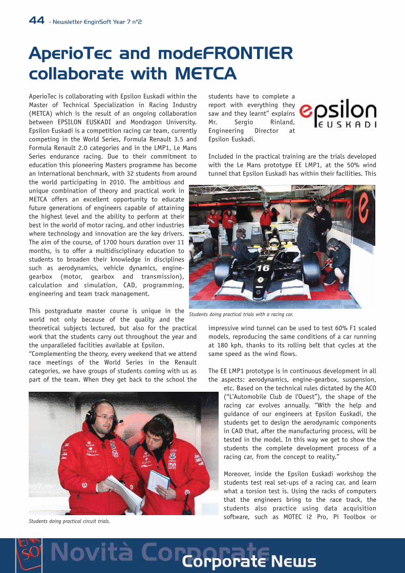
44 - Newsletter EnginSoft Year 7 n°2
AperioTec and modeFRONTIER collaborate with METCAAperioTec is collaborating with Epsilon Euskadi within theMaster of Technical Specialization in Racing Industry(METCA) which is the result of an ongoing collaborationbetween EPSILON EUSKADI and Mondragon University.Epsilon Euskadi is a competition racing car team, currentlycompeting in the World Series, Formula Renault 3.5 andFormula Renault 2.0 categories and in the LMP1, Le MansSeries endurance racing. Due to their commitment toeducation this pioneering Masters programme has becomean international benchmark, with 32 students from aroundthe world participating in 2010. The ambitious andunique combination of theory and practical work inMETCA offers an excellent opportunity to educatefuture generations of engineers capable of attainingthe highest level and the ability to perform at theirbest in the world of motor racing, and other industrieswhere technology and innovation are the key drivers.The aim of the course, of 1700 hours duration over 11months, is to offer a multidisciplinary education tostudents to broaden their knowledge in disciplinessuch as aerodynamics, vehicle dynamics, engine-gearbox (motor, gearbox and transmission),calculation and simulation, CAD, programming,engineering and team track management.
This postgraduate master course is unique in theworld not only because of the quality and thetheoretical subjects lectured, but also for the practicalwork that the students carry out throughout the year andthe unparalleled facilities available at Epsilon.“Complementing the theory, every weekend that we attendrace meetings of the World Series in the Renaultcategories, we have groups of students coming with us aspart of the team. When they get back to the school the
students have to complete areport with everything theysaw and they learnt” explainsMr. Sergio Rinland,Engineering Director atEpsilon Euskadi.
Included in the practical training are the trials developedwith the Le Mans prototype EE LMP1, at the 50% windtunnel that Epsilon Euskadi has within their facilities. This
impressive wind tunnel can be used to test 60% F1 scaledmodels, reproducing the same conditions of a car runningat 180 kph, thanks to its rolling belt that cycles at thesame speed as the wind flows.
The EE LMP1 prototype is in continuous development in allthe aspects: aerodynamics, engine-gearbox, suspension,
etc. Based on the technical rules dictated by the ACO(“L'Automobile Club de l'Ouest”), the shape of theracing car evolves annually. “With the help andguidance of our engineers at Epsilon Euskadi, thestudents get to design the aerodynamic componentsin CAD that, after the manufacturing process, will betested in the model. In this way we get to show thestudents the complete development process of aracing car, from the concept to reality.”
Moreover, inside the Epsilon Euskadi workshop thestudents test real set-ups of a racing car, and learnwhat a torsion test is. Using the racks of computersthat the engineers bring to the race track, thestudents also practice using data acquisitionsoftware, such as MOTEC i2 Pro, Pi Toolbox or
Students doing practical circuit trials.
Students doing practical trials with a racing car.

Newsletter EnginSoft Year 7 n°2 - 45
Magneti Marelli Wintax 3, analyzingexamples of real data and real problemsthat they could face in the real racingworld.
To support the quality of the lectures and the practicalwork, Epsilon Euskadi has prepared one of the bestclassrooms in Europe, if not from all over the world. Theseclassrooms have implemented some of the mostinteresting solutions for the new educational age andhave made Epsilon become the indisputable leader inMotorsport Education.
The workstation that each student has for his/her ownuse during the course duration is a dual quad-core DELLR5400. These workstations have 16GB RAM memory andNvidia Quadro Pro Fx graphic cards with 1.5GB memory.Each computer has two 20 inch screens with a totaldesktop resolution of 3060x1050. When these machinesare connected in parallel, to compute for example acomplex CFD simulation case, the computation capacityis 528GB. All this computational power is completelyassigned for METCA use, always with the help and theassistance of the trainers and engineers of EpsilonEuskadi.
The whole system has been designed with the know-howof Epsilon, and all computers are physically set inside the
Data Center that also contains all the network and dataprocessing equipment. To achieve a good communicationbetween the Data Center and the terminals situated in theclassrooms, Epsilon has one of the most advanced and fastsystems of telecommunications in the world. Based on theVSS Technology (Virtual Switching System) and with acommutation capacity in core of 10GB, the networkoperates at 1GB transmission per second between theworkstations and the terminals.
The engineering applications that the students addressduring the course require capable software and thesesoftware tools will be learnt and applied to engineeringapplications. The software tools used, for example, areCATIA V5 for CAD, Abaqus for Finite Element Analysis,Star-CCM+ for Computational Fluid Dynamics, SIMPACK forkinematic and dynamic simulations and modeFRONTIER(APERIO Technology) to define the simulation andoptimization processes using the different simulation andcalculation tools.
Another peculiarity is the opaque chamber installed onthe trainer’s desk allowing components to be shown to the
students with great definition and clarity. This systemallows the display of component details that wouldotherwise be complicated to assess. The projection ofthese images is performed by two overhead projectorswith 4000 lumen capacity.
The traditional blackboard is still present even though theclassroom has a whiteboard system that allows the trainerto create graphics and annotations that students can seeon their own screens.
Finally, a 3D printer or rapid prototyping machine isincluded. This impressive machine, courtesy of ourtechnology partner Pixel Systems, allows three-dimensional parts to be "printed" based on the CADdesign. The components that are designed andmanufactured by the students using this machine are latertrailed in the wind tunnel undertaken with the EpsilonEuskadi Le Mans model.
Gino Duffett, Director de AperioTec, with the Le Mans series and Le Mans 24hours prototype car.
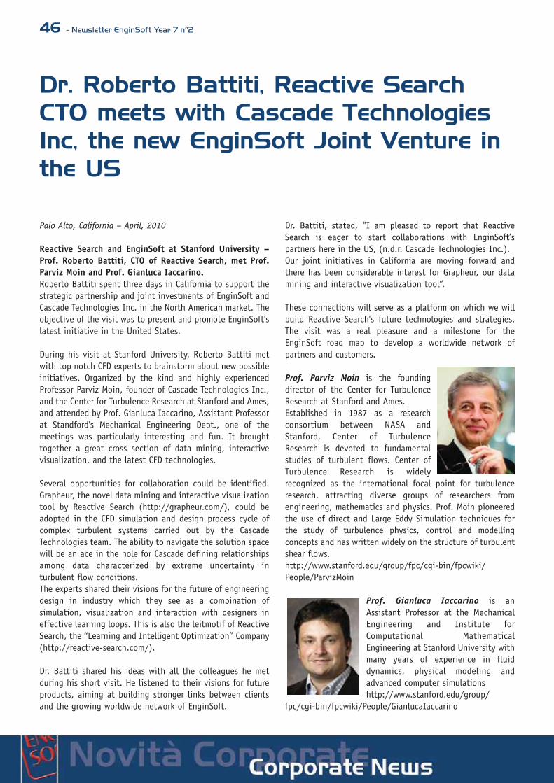
46 - Newsletter EnginSoft Year 7 n°2
Dr. Roberto Battiti, Reactive SearchCTO meets with Cascade TechnologiesInc, the new EnginSoft Joint Venture inthe US
Palo Alto, California – April, 2010
Reactive Search and EnginSoft at Stanford University –Prof. Roberto Battiti, CTO of Reactive Search, met Prof.Parviz Moin and Prof. Gianluca Iaccarino.Roberto Battiti spent three days in California to support thestrategic partnership and joint investments of EnginSoft andCascade Technologies Inc. in the North American market. Theobjective of the visit was to present and promote EnginSoft'slatest initiative in the United States.
During his visit at Stanford University, Roberto Battiti metwith top notch CFD experts to brainstorm about new possibleinitiatives. Organized by the kind and highly experiencedProfessor Parviz Moin, founder of Cascade Technologies Inc.,and the Center for Turbulence Research at Stanford and Ames,and attended by Prof. Gianluca Iaccarino, Assistant Professorat Standford's Mechanical Engineering Dept., one of themeetings was particularly interesting and fun. It broughttogether a great cross section of data mining, interactivevisualization, and the latest CFD technologies.
Several opportunities for collaboration could be identified.Grapheur, the novel data mining and interactive visualizationtool by Reactive Search (http://grapheur.com/), could beadopted in the CFD simulation and design process cycle ofcomplex turbulent systems carried out by the CascadeTechnologies team. The ability to navigate the solution spacewill be an ace in the hole for Cascade defining relationshipsamong data characterized by extreme uncertainty inturbulent flow conditions.The experts shared their visions for the future of engineeringdesign in industry which they see as a combination ofsimulation, visualization and interaction with designers ineffective learning loops. This is also the leitmotif of ReactiveSearch, the “Learning and Intelligent Optimization” Company(http://reactive-search.com/).
Dr. Battiti shared his ideas with all the colleagues he metduring his short visit. He listened to their visions for futureproducts, aiming at building stronger links between clientsand the growing worldwide network of EnginSoft.
Dr. Battiti, stated, "I am pleased to report that ReactiveSearch is eager to start collaborations with EnginSoft’spartners here in the US, (n.d.r. Cascade Technologies Inc.).Our joint initiatives in California are moving forward andthere has been considerable interest for Grapheur, our datamining and interactive visualization tool”.
These connections will serve as a platform on which we willbuild Reactive Search's future technologies and strategies.The visit was a real pleasure and a milestone for theEnginSoft road map to develop a worldwide network ofpartners and customers.
Prof. Parviz Moin is the foundingdirector of the Center for TurbulenceResearch at Stanford and Ames.Established in 1987 as a researchconsortium between NASA andStanford, Center of TurbulenceResearch is devoted to fundamentalstudies of turbulent flows. Center ofTurbulence Research is widelyrecognized as the international focal point for turbulenceresearch, attracting diverse groups of researchers fromengineering, mathematics and physics. Prof. Moin pioneeredthe use of direct and Large Eddy Simulation techniques forthe study of turbulence physics, control and modellingconcepts and has written widely on the structure of turbulentshear flows.http://www.stanford.edu/group/fpc/cgi-bin/fpcwiki/People/ParvizMoin
Prof. Gianluca Iaccarino is anAssistant Professor at the MechanicalEngineering and Institute forComputational MathematicalEngineering at Stanford University withmany years of experience in fluiddynamics, physical modeling andadvanced computer simulationshttp://www.stanford.edu/group/
fpc/cgi-bin/fpcwiki/People/GianlucaIaccarino
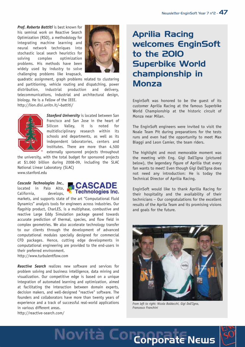
Newsletter EnginSoft Year 7 n°2 - 47
Prof. Roberto Battiti is best known forhis seminal work on Reactive SearchOptimization (RSO), a methodology forintegrating machine learning andneural network techniques intostochastic local search heuristics forsolving complex optimizationproblems. His methods have beenwidely used by industry to solvechallenging problems like knapsack,quadratic assignment, graph problems related to clusteringand partitioning, vehicle routing and dispatching, powerdistribution, industrial production and delivery,telecommunications, industrial and architectural design,biology. He is a Fellow of the IEEE. http://lion.disi.unitn.it/~battiti/
Stanford University is located between SanFrancisco and San Jose in the heart ofSilicon Valley, it is noted formultidisciplinary research within itsschools and departments, as well as itsindependent laboratories, centers andinstitutes. There are more than 4,500externally sponsored projects throughout
the university, with the total budget for sponsored projectsat $1.060 billion during 2008-09, including the SLACNational Linear Laboratory (SLAC)www.stanford.edu
Cascade Technologies Inc.,located in Palo Alto,California, develops,markets, and supports state of the art “Computational FluidDynamics” analysis tools for engineers across industries. Ourflagship product, CharLES, is a multiphase, combustive andreactive Large Eddy Simulation package geared towardsaccurate prediction of thermal, species, and flow field incomplex geometries. We also accelerate technology transferto our clients through the development of advancedcomputational modules specially designed for commercialCFD packages. Hence, cutting edge developments incomputational engineering are provided to the end-users intheir preferred environment.http://www.turbulentflow.com
Reactive Search realizes new software and services forproblem solving and business intelligence, data mining andvisualization. Our competitive edge is based on a uniqueintegration of automated learning and optimization, aimedat facilitating the interaction between domain experts,decision makers, and well-designed "reactive" software. Thefounders and collaborators have more than twenty years ofexperience and a track of successful real-world applicationsin various different areas.http://reactive-search.com/
Aprilia Racing welcomes EnginSoftto the 2010Superbike World championship inMonza
EnginSoft was honored to be the guest of itscustomer Aprilia Racing at the famous SuperbikeWorld Championship at the historic circuit ofMonza near Milan.
The EnginSoft engineers were invited to visit theNoale Team Pit during preparations for the testsruns and even had the opportunity to meet MaxBiaggi and Leon Camier, the team riders.
The highlight and most memorable moment wasthe meeting with Eng. Gigi Dall'Igna (picturedbelow), the legendary figure of Aprilia that everyfan wants to meet! Even though Gigi Dall'Igna doesnot need any introduction: He is today theTechnical Director of Aprilia Racing.
EnginSoft would like to thank Aprilia Racing fortheir hospitality and the availability of theirtechnicians – Our congratulations for the excellentresults of the Aprila Team and its promising visionsand goals for the future.
From left to right: Nicola Baldecchi, Gigi Dall’Igna,Francesco Franchini

48 - Newsletter EnginSoft Year 7 n°2
L’esperienza di un leader mondiale: Sapa
Leader mondiale tra le aziende che operanonel settore dell'alluminio, giorno dopo giornoSapa consolida la sua presenza in Europa e nelmondo.Tutto in Sapa presta particolare attenzione alle persone,Sapa cresce insieme alle persone che vi lavorano le quali,tutte orientate al cliente, sono sempre in grado di fornirele soluzioni a più alto valore aggiunto.Nel settore dei sistemi per l'edilizia, Teknowindow,Teknowall e Sistema R sono i marchi di prodotti che sicontraddistinguono sul mercato per l'affidabilità, la fun-zionalità, la qualità e la semplicità di lavorazione e mon-taggio.
Sapa offre un pro-dotto di qualità egarantito mettendoa disposizione deipropri "partners"tutte le conoscenzetecnologiche che
sono il risultato di un investimento costante, in tutto ilmondo, giorno dopo giorno, nella ricerca e sviluppo nelsettore dell'alluminio.
Sapa, leader mondiale nell'estrusione dell'alluminio, ser-vendo i mercati ed i clienti più disparati (IKEA, Audi,Bombardier, Solsonica, Marconi, Alenia, Beretta,Brembo…) è in grado di mutuare le diverse esperienze ac-quisite in un dato mercato negli altri, mettendo a dispo-sizione dei propri clienti la tecnologia per sviluppare sem-pre nuove soluzioni ed applicazioni. Oltre a ciò, la gammadei prodotti Sapa include profili commerciali standard co-me Flutzi, tubi e barrame,Visitate il sito Sapa all'indirizzo:www.sapagroup.com
L’utilizzo di ANSYS nella progettazioneL'utilizzo di ANSYS è previsto per analisi sta-tiche su strutture realizzare con profilati in al-luminio, come ad esempio serre, strutturefrangisole fotovoltaiche, parcheggi, ecc.ANSYS verrà utilizzato anche per analisi cheprevedono non linearità di materiale o di con-tatto (pale eoliche, corpi pompa, componen-tistica meccanica, giunti bullonati);Inoltre è previsto l'utilizzo di ANSYS sia peranalisi meccaniche con modelli parametrici
per ottimizzazione della geometria cheper analisi termiche in regime stazio-nario su dissipatori di calore alettati.
Perché EnginSoft ed ANSYS in Sapa Group“Da sempre la Sapa Group è favorevole e sposa le soluzio-ni software che ci possono fornire un valore aggiunto dalpunto di vista della Ricerca e Sviluppo” - ha dichiaratol'Ing. Alberto Terenzi Sales Engineer della divisione italia-na di Sapa – “e in questa ottica ANSYS ha dimostrato diavere tutte le caratteristiche necessarie per essere valuta-to positivamente… a valle di una serie di attente valuta-
zione tecniche abbiamo scelto ANSYS perché rappresentaa nostro avviso la migliore tecnologia attualmente presen-te sul mercato nel campo dei software di analisi struttura-le” – ha continuato l'Ing. Terenzi – “inoltre la EnginSoftha dato prova di essere un partner serio ed affidabile checi ha aiutato nel migliore dei modi nella fase iniziale diutilizzo del software e nell'assistenza tecnica post-vendita”.

Newsletter EnginSoft Year 7 n°2 - 49
EnginSoft partecipa al METEF 2010
La Fiera METEF, expo internazionalededicata alla filiera produttiva dell'al-luminio e dei metalli non ferrosi, èuno degli eventi di maggior rilievo edi richiamo internazionale che si oc-cupa di tecniche e tecnologie innova-tive per l'industria fusoria.La Fiera ha cadenza biennale e si èsvolta al Centro Fiera di Montichiari dal 14 al 17 aprile2010. L’edizione 2010 ha registrato 15.766 presenze(espositori esclusi).
Da alcune edizioni EnginSoft partecipa alla manifestazio-ne con un proprio spazio espositivo e nelle ultime edizio-
ni, inclusa quella dell’anno corrente, EnginSoft ha presen-ziato assieme al partner tedesco MAGMA, mostrando ai vi-sitatori i vantaggi offerti dalle più avanzate tecniche di si-mulazione virtuale dei vari processi di pressocolata, non-ché alcune storie di successo di alcune aziende italianeche hanno utilizzato il softwareMAGMAsoft.
Nell'occasione, in particolare, EnginSoftha presentato MAGMA5, la nuova releasedi MAGMAsoft, che riguarda principalmen-te i processi di colata in SABBIA per legheferrose e non ferrose. MAGMA5 è basatosulle più recenti tecnologie software epermette di creare e gestire i modelli inmodo più semplice, impostare la simula-zione e visualizzare in maniera efficiente irisultati. Questo nuovo ambiente CAD per-mette l’integrazione con gli altri CAD com-merciali, offrendo la possibilità di impor-tare ed esportare file geometrici di vari
formati: all’interfaccia STL si potràaffiancare il formato STEP per un pe-riodo di prova di un anno senza co-sti aggiuntivi, mentre diventano di-sponibili come opzioni attivabili an-che le interfacce CATIA V5 (solo perle piattaforme Windows) e Pro/E.
Oltre alla presenza con il proprio spazio espositivoEnginSoft è anche intervenuta in due importanti convegniorganizzati il giorno venerdì 16 aprile:• Difettologia dei pressocolati – presentazione del nuo-
vo "Manuale di difettologia" organizzato da AIM –Associazione Italiana di Metallurgia, Centro StudiPressocolata (con intervento di P. Parona – ancheautore del manuale - dal titolo “Esempi di simulazionenumerica di difetti”).
• Progetto di ricerca NADIA - presentazione risultati delprogetto europeo "New Automotive componentsDesigned for a manufactured by Intelligent processingof light Alloys".
Interventi di: • Ing. S. Odorizzi, “Il progetto NADIA: una breve pano-
ramica”. • N. Gramegna, assieme a R. Molina (Teksid Aluminium),
“Componenti motore progettati e realizzati utilizzandonuove leghe e nuovi processi”.
• N. Gramegna, assieme a I. Loizaga (CIE Automotive),“La previsione del comportamento meccanico di gettipresso colati in alluminio per il settore automotive”.
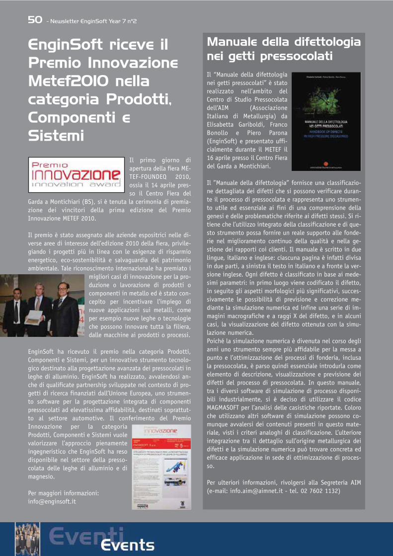
50 - Newsletter EnginSoft Year 7 n°2
EnginSoft riceve ilPremio InnovazioneMetef2010 nella categoria Prodotti,Componenti eSistemi
Il primo giorno diapertura della fiera ME-TEF-FOUNDEQ 2010,ossia il 14 aprile pres-so il Centro Fiera del
Garda a Montichiari (BS), si è tenuta la cerimonia di premia-zione dei vincitori della prima edizione del PremioInnovazione METEF 2010.
Il premio è stato assegnato alle aziende espositrici nelle di-verse aree di interesse dell’edizione 2010 della fiera, privile-giando i progetti più in linea con le esigenze di risparmioenergetico, eco-sostenibilità e salvaguardia del patrimonioambientale. Tale riconoscimento internazionale ha premiato i
migliori casi di innovazione per la pro-duzione o lavorazione di prodotti ocomponenti in metallo ed è stato con-cepito per incentivare l’impiego dinuove applicazioni sui metalli, comeper esempio nuove leghe o tecnologieche possono innovare tutta la filiera,dalle macchine ai prodotti o processi.
EnginSoft ha ricevuto il premio nella categoria Prodotti,Componenti e Sistemi, per un innovativo strumento tecnolo-gico destinato alla progettazione avanzata dei pressocolati inleghe di alluminio. EnginSoft ha realizzato, avvalendosi an-che di qualificate partnership sviluppate nel contesto di pro-getti di ricerca finanziati dall’Unione Europea, uno strumen-to software per la progettazione integrata di componentipressocolati ad elevatissima affidabilità, destinati soprattut-to al settore automotive. Il conferimento del PremioInnovazione per la categoriaProdotti, Componenti e Sistemi vuolevalorizzare l’approccio pienamenteingegneristico che EnginSoft ha resodisponibile nel settore della presso-colata delle leghe di alluminio e dimagnesio.
Per maggiori informazioni: [email protected]
Manuale della difettologianei getti pressocolatiIl “Manuale della difettologianei getti pressocolati” è statorealizzato nell’ambito delCentro di Studio Pressocolatadell’AIM (AssociazioneItaliana di Metallurgia) daElisabetta Gariboldi, FrancoBonollo e Piero Parona(EnginSoft) e presentato uffi-cialmente durante il METEF il16 aprile presso il Centro Fieradel Garda a Montichiari.
Il ”Manuale della difettologia” fornisce una classificazio-ne dettagliata dei difetti che si possono verificare duran-te il processo di pressocolata e rappresenta uno strumen-to utile ed essenziale ai fini di una comprensione dellagenesi e delle problematiche riferite ai difetti stessi. Si ri-tiene che l’utilizzo integrato della classificazione e di que-sto strumento possa fornire un reale supporto alle fonde-rie nel miglioramento continuo della qualità e nella ge-stione dei rapporti coi clienti. Il manuale è scritto in duelingue, italiano e inglese: ciascuna pagina è infatti divisain due parti, a sinistra il testo in italiano e a fronte la ver-sione inglese. Ogni difetto è classificato in base ai mede-simi parametri: in primo luogo viene codificato il difetto,in seguito gli aspetti morfologici più significativi, succes-sivamente le possibilità di previsione e correzione me-diante la simulazione numerica ed infine una serie di im-magini macrografiche e a raggi X del difetto, e in alcunicasi, la visualizzazione del difetto ottenuta con la simu-lazione numerica. Poiché la simulazione numerica è divenuta nel corso deglianni uno strumento sempre più affidabile per la messa apunto e l’ottimizzazione dei processi di fonderia, inclusala pressocolata, è parso quindi essenziale introdurla comeelemento di descrizione, visualizzazione e previsione deidifetti del processo di pressocolata. In questo manuale,tra i diversi software di simulazione di processo disponi-bili industrialmente, si è deciso di utilizzare il codiceMAGMASOFT per l’analisi delle casistiche riportate. Coloroche utilizzano altri software di simulazione possono co-munque avvalersi dei contenuti presenti in questo mate-riale, visti i criteri analoghi di classificazione. L’ulterioreintegrazione tra il dettaglio sull’origine metallurgica deidifetti e la simulazione numerica può trovare concreta edefficace applicazione in sede di ottimizzazione di proces-so.
Per ulteriori informazioni, rivolgersi alla Segreteria AIM(e-mail: [email protected] - tel. 02 7602 1132)

Newsletter EnginSoft Year 7 n°2 - 51
CONFERENZA NADIALeghe leggere per l’automotive: le sfide del Progetto NADIAIl titolo del seminario rende merito agli obietti-vi perseguiti nell’ambito del progetto NADIA e il-lustrati, nella loro forma più significativa, dai re-ferenti industriali all’interno di un evento ospita-to presso il centro congressi del METEF.METEF rappresenta la cornice ideale per ospitareun tale evento in quanto si contraddistingue co-me punto di incontro delle eccellenze nel setto-re del manufacturing delle leghe non-ferrose e il loro uti-lizzo a livello industriale.
NADIA (New Automotive components Designed for andmanufactured by Intelligent processing of light Alloys,Contract n. 026563-2) è un progetto finanziatodall’Unione Europea per un ammontare di 7.2 milioni diEuro, che ha coinvolto, nel periodo 2006-2010 27 partnersindustriali, centri di ricerca ed universitari, con particola-re attenzione alle piccole medie imprese che costituisco-no la maggioranza del tessuto produttivo europeo. NADIAè stato finalizzato alla valutazione del potenziale, nell’am-bito dell’industria europea dei trasporti, delle leghe legge-re per la realizzazione di componenti automotive basatisull’utilizzo di nano- e micro-tecnologie.
S. Odorizzi (ENGINSOFT), responsabile del coordinamentodel progetto, ha avuto l’onore di introdurre gli aspettichiave del progetto e la struttura, assai complessa, di unimpegnativo progetto integrato grazie al supporto del co-ordinatore scientifico F. Bonollo (DTG).
La presentazione di L. Anberg (NTNU) ha illustrato la cor-relazione fra i difetti derivanti dai processi di colata e pre-stazioni meccaniche delle leghe leggere con particolareattenzione alla previsione della porosità da idrogeno nei
getti in lega d'alluminio. In fatti, il modello di previsionedella microporosità e segregazione di idrogeno costituisceuno degli aspetti innovativi del progetto spostando la sca-la di valutazione a livello interdendritico, in funzione del-la composizione della lega e dei parametri di processo, percomprendere il comportamento meccanico dell’intero com-ponente automobilistico.
È ovviamente difficile sintetizzare in un seminario l’artico-lato progetto durato quattro anni, ad ogni modo, W. Rhem(DAIMLER), U. Weiss (FORD), R. Molina (TEKSID) e I.Loizaga (Fundacion CIE) hanno descritto i risultati a par-tire dalla ricerca di base ma sottolineando soprattutto ibenefici dell’applicazione industriale delle nuove cono-scenze e modelli CAE. La fase finale del progetto, comechiaramente espresso dai singoli relatori, vede la defini-zione di modelli avanzati per le leghe leggere che correla-no il processo produttivo di fonderia alle performance delmateriale e la loro implementazione nelle procedure diprogettazione integrata, comunemente denominataDesign Chain. Il progetto integrato si conclude con l’ap-plicazione degli strumenti CAE (simultaneous engineering& manufacturing approach for High Tech components) e iltest a livello di componenti industriali, quali una testa ci-lindri, un blocco motore, un componente telaio in lega dimagnesio e una scatola sterzo.
Il progetto NADIA è stato insignito del “PremioInnovazione METEF 2010” per la categoria “Tecnologie diEngineering” a riprova degli ottimi risultati ottenuti, tra iquali l’innovazione per la progettazione multiscala & inge-gneria simultanea che è stato esteso e reso disponibileanche ai componenti presso colati.
Come rimarcato da S. Odorizzi, un ringraziamento è rivol-to al comitato organizzatore del METEF ma soprattutto atutti i partner che hanno svolto con dedizione e professio-nalità le attività pianificate con pregevole collaborazionea livello europeo.
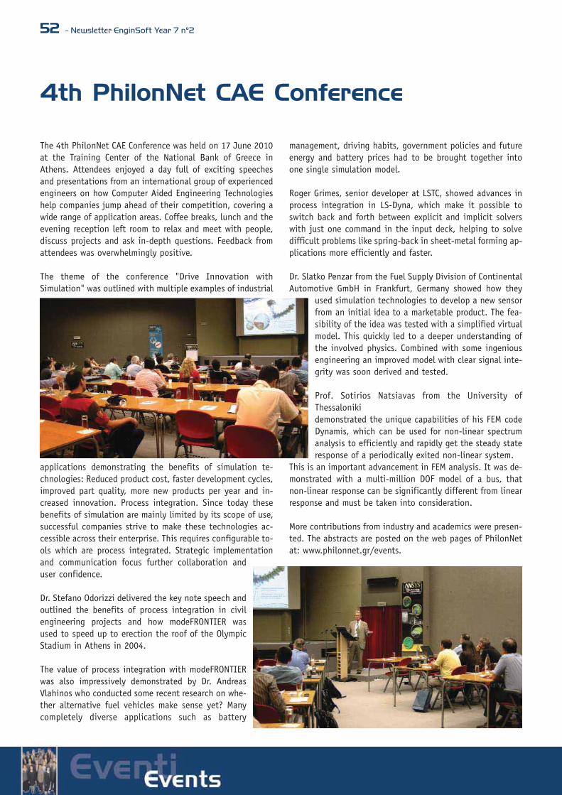
52 - Newsletter EnginSoft Year 7 n°2
The 4th PhilonNet CAE Conference was held on 17 June 2010at the Training Center of the National Bank of Greece inAthens. Attendees enjoyed a day full of exciting speechesand presentations from an international group of experiencedengineers on how Computer Aided Engineering Technologieshelp companies jump ahead of their competition, covering awide range of application areas. Coffee breaks, lunch and theevening reception left room to relax and meet with people,discuss projects and ask in-depth questions. Feedback fromattendees was overwhelmingly positive.
The theme of the conference "Drive Innovation withSimulation" was outlined with multiple examples of industrial
applications demonstrating the benefits of simulation te-chnologies: Reduced product cost, faster development cycles,improved part quality, more new products per year and in-creased innovation. Process integration. Since today thesebenefits of simulation are mainly limited by its scope of use,successful companies strive to make these technologies ac-cessible across their enterprise. This requires configurable to-ols which are process integrated. Strategic implementationand communication focus further collaboration anduser confidence.
Dr. Stefano Odorizzi delivered the key note speech andoutlined the benefits of process integration in civilengineering projects and how modeFRONTIER wasused to speed up to erection the roof of the OlympicStadium in Athens in 2004.
The value of process integration with modeFRONTIERwas also impressively demonstrated by Dr. AndreasVlahinos who conducted some recent research on whe-ther alternative fuel vehicles make sense yet? Manycompletely diverse applications such as battery
management, driving habits, government policies and futureenergy and battery prices had to be brought together intoone single simulation model.
Roger Grimes, senior developer at LSTC, showed advances inprocess integration in LS-Dyna, which make it possible toswitch back and forth between explicit and implicit solverswith just one command in the input deck, helping to solvedifficult problems like spring-back in sheet-metal forming ap-plications more efficiently and faster.
Dr. Slatko Penzar from the Fuel Supply Division of ContinentalAutomotive GmbH in Frankfurt, Germany showed how they
used simulation technologies to develop a new sensorfrom an initial idea to a marketable product. The fea-sibility of the idea was tested with a simplified virtualmodel. This quickly led to a deeper understanding ofthe involved physics. Combined with some ingeniousengineering an improved model with clear signal inte-grity was soon derived and tested.
Prof. Sotirios Natsiavas from the University ofThessalonikidemonstrated the unique capabilities of his FEM codeDynamis, which can be used for non-linear spectrumanalysis to efficiently and rapidly get the steady stateresponse of a periodically exited non-linear system.
This is an important advancement in FEM analysis. It was de-monstrated with a multi-million DOF model of a bus, thatnon-linear response can be significantly different from linearresponse and must be taken into consideration.
More contributions from industry and academics were presen-ted. The abstracts are posted on the web pages of PhilonNetat: www.philonnet.gr/events.
4th PhilonNet CAE Conference


54 - Newsletter EnginSoft Year 7 n°2
International modeFRONTIER Users’Meeting 2010ESTECO modeFRONTIER International Users’ Meeting 2010 took place in the beautiful city of Trieste, Italy (27th and 28th May 2010, Starhotel Savoia Excelsior Palace)
The conference provided an opportunityto learn how modeFRONTIER is usedglobally by designers and managers inmany industries all over the world. Itsupplied a platform for exchanging ideasand views across a wide range of high-tech industrial sectors engaging
technologists from leading companies of the like of FIAT,Honda, Jaguar, Bombardier and many more. The welcome speech of Prof. Carlo Poloni, President ofESTECO, introduced the leit-motiv of the meeting: “goinggreen” or “how having better products results in better careof the environment”. The use of modeFRONTIER amongseveral industrial application areas, was highlighted as apowerful tool to help designers in reducing pollution and theenvironmental impact of an industrial activity.
Poloni presented a normal day of business for a person inEurope: drinking coffee, using domestic appliances andtravelling by plane, train and car result in Kg of CO2 releasedin the atmosphere. When modeFRONTIER is used in thedesign of the manufacturing process lots of CO2 emissions arereduced. As an example Brazilian plane manufacturer Embraerobtained 1 count of additional drag reduction afterintroducing modeFRONTIER optimization environment intheir design process loop. BMW car manufacturer showed areduction of about 16% fuel consumption for their cars withtheir enhanced models optimized with modeFRONTIER andBombardier fast train achieved a 15% tractionenergy reduction. Electrolux diminished 1Kg of CO2
emissions for any washing machine produced whileIlly coffee maker optimized its Iperespresso®capsule packing with 0.7 Kg CO2 emission less foreach piece. Take all this and multiply it by about 7millions of people who transit each day by one ofthe smaller sized airports in Europe and you’ll getimmediately an idea of the advantage.The conference saw several industry expertspresenting case studies and specialized sessionsfocused on different areas. Aeronautical problem-solving, automotive innovation, green designprocess and life-science related engineering
optimization were all in the spotlight during the two days ofthe meeting. Several complex project involving multi-disciplinary toolswere pictured as streamlined by modeFRONTIER process flowintegration, granting easy problem-solving procedures. Inparticular, during the first Keynote Session, Embraerengineers presented how modeFRONTIER platform is sharedby different departments to deliver a truly optimized solutionwhich includes several different requirements coming fromdepartments as the structural department, CFD, noise and soon. They are able to design a wholly optimized aircraft andprove that modeFRONTIER allows taking parametric CAE-CADmodeling automation to the next level.Jaguar and Ford, pioneers users of modeFRONTIER, exposedan overview of the achievements reached with ESTECOsoftware that made them internal testimonials of thebenefits of MDO (Multidisciplinary Design Optimization).From crash analysis, to occupant restraint systemoptimization; from NVH (noise-vibration-harshness) for asafer and more comfortable product, to CFD for externalaerodynamics and fuel cells, most sections of the designprocess were exhibited as enhanced by modeFRONTIERoptimization.
On the subject of external aerodynamics, Ferrari proposed itsoptimised rear diffuser of a GT sport-car by parametric CFDanalysis driven up by modeFRONTIER, while Fiat ResearchCenter used parametric mesh morpher ANSA connected by
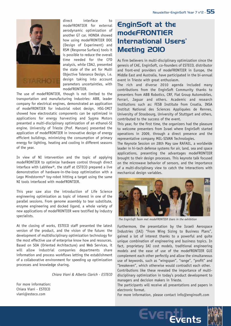
EnginSoft at themodeFRONTIERInternational Users’Meeting 2010 As firm believers in multi-disciplinary optimization since thegenesis of CAE, EnginSoft, co-founders of ESTECO, distributorand front-end providers of modeFRONTIER in Europe, theMiddle East and Australia, have participated in the bi-annualevent in Trieste with great enthusiasm.The rich and diverse 2010 agenda included manycontributions from the EnginSoft Community thanks topresenters from ABB Robotics, CRF, Fiat Group Automobiles,Ferrari, Jaguar and others. Academic and researchinstitutions such as: FESB Institute from Croatia, INSAInstitut National des Sciences Appliquées de Rennes,University of Strasbourg, University of Stuttgart and others,contributed to the success of the event.This year, for the first time, the organizers had the pleasureto welcome presenters from Israel where EnginSoft startedoperations in 2009, through a direct presence and therepresentative company MEL-SIVAN Technologies.The Keynote Session on 28th May saw RAFAEL, a worldwideleader in hi-tech defense systems for air, land, sea and spaceapplications, presenting the advantages modeFRONTIERbrought to their design processes. This keynote talk focusedon the microwave behavior of sensors, and the importanceof a multi-disciplinary view to catch the interactions withmechanical design variables.
Furthermore, the presentation by the Israeli AerospaceIndustries (IAI) “From Wing Sizing to Business Plans”,gained a lot of interest thanks to a powerful and quiteunique combination of engineering and business topics. Infact, proprietary IAI cost models, traditional engineeringmodels and the ease of use of the modeFRONTIER GUIcomplement each other perfectly and allow the simultaneoususe of keywords, such as “wingspan”, “range”, “profit” and“breakeven”, which otherwise would contradict each other. Contributions like these revealed the importance of multi-disciplinary optimization in today’s product development tomanagers and decision makers in Trieste.The participants will receive all presentations and papers inelectronic format.For more information, please contact [email protected]
direct interface tomodeFRONTIER for externalaerodynamic optimization ofanother GT car. HONDA showedhow using modeFRONTIER DOE(Design of Experiment) andRSM (Response Surface) tools itis possible to reduce the overalltime needed for the CFDanalysis, while CDAJ, presentedthe state of the art for MultiObjective Tolerance Design, i.e.design taking into accountparameters uncertainties, withmodeFRONTIER.
The use of modeFRONTIER, though is not limited to thetransportation and manufacturing industries: ABB, leadercompany for electrical engines, demonstrated an applicationof modeFRONTIER for industrial robot design, HSG-IMITshowed how electrostatic components can be optimized inapplications for energy harvesting and Sygma Motorspresented a multi-disciplinary optimization of an ethanol-SIengine. University of Trieste (Prof. Manzan) presented theapplication of modeFRONTIER in innovative design of energyefficient buildings, minimizing the consumption of primaryenergy for lighting, heating and cooling in different seasonsof the year.
In view of NI intervention and the topic of applyingmodeFRONTIER to optimize hardware control through directinterface with LabView®, the staff at ESTECO prepared a livedemonstration of hardware-in-the-loop optimization with aLego Mindstorms® toy-robot hitting a target using the sameNI tools interfaced with modeFRONTIER.
This year saw also the introduction of Life Scienceengineering optimization as topic of interest in one of theparallel sessions. From genome assembly to tear substitute,enzyme engineering and docked ligand, a whole variety ofnew applications of modeFRONTIER were testified by industryspecialists.
At the closing of works, ESTECO staff presented the latestversion of the product, and the vision of the future: thedevelopment of multidisciplinary optimization technology forthe most effective use of enterprise know how and resources.Based on SOA (Oriented Architecture) and Web Services, itwill allow industrial companies departments shareinformation and process workflows letting the establishmentof a collaborative environment for speeding up optimizationprocesses and knowledge sharing.
Chiara Viani & Alberto Clarich - ESTECO
For more information:Chiara Viani - [email protected]
Newsletter EnginSoft Year 7 n°2 - 55
The EnginSoft Team met modeFRONTIER Users in the exhibition

56 - Newsletter EnginSoft Year 7 n°2
APMS 2010Third Announcement and Call for Papers
The recent financial global crisis has accelerated the needfor a sustainable economic growth where smarter and gree-ner economy could create prosperity and new job from in-novation and from using the natural resources better thanbefore. In this global context, besides the role of the poli-cy makers, companies cannot postpone anymore the imple-mentation of strategies to deal with an increasing compe-tition in a sustainable, green and environmental-consciousand social-oriented market: strict regulations, consumersdemand for greener products, reduction of the carbon foot-print, optimization of the usage of natural resources, moresocietal attention and many other trends are increasing thechallenges to compete in a real global market. Companiesare therefore called to become more efficient, increasetheir productivity, use less resources and non-renewableenergy in an environment with high energy prices, carbonconstraints and greater resource competition.
These challenges require a deep rethinking of the role ofManufacturing with the need for new approaches toProduct, Service and Production Management: from a cost-cutting to a multi-disciplinary knowledge-based eco-facto-ry model. With this goal inmind, APMS2010 calls for new,innovative and original scienti-fic contributions which addresspractical and industrial-orien-ted solutions where the abovecontext is addressed.
APMS 2010 at a glanceSince several decades, APMS is one of the major events andthe official conference of the IFIP Working Group 5.7 onAdvances in Production Management Systems.APMS 2010 will take place in Cernobbio (Como Lake, Italy),11-13 October 2010.
Some numbers about APMS2010:• Doctoral Workshop (9-10 October 2010),• Special Sessions have been published• 4 Projects have already joined the conference• 2 keynote speakers have already confirmed their
presentation:• Mr. Salvatore Paparelli, AV Sales & Operations Director,
Sony Italy - The Sony’s Way to Sustainability: Product,
Process, Planet: The Impacton Manufacturing,Operations, Products andWaste
• Massimo Mattucci, COO Comau- Enviromental, Economicaland Social Sustainability:Comau’s Business Evolution inProduction Systems andServices
Important dates• 15 April 2010 30 April 2010 Submission of Extended
Abstract (min. 2.000 words)• 15 May 2010 Notification of acceptance• 1 July 2010 Final paper and registration fee due• 9-10 October 2010 Doctoral Workshop• 11-12-13 October 2010 APMS 2010 Conference
Conference topicsAPMS 2010 will be dedicated to Competitive andSustainable Manufacturing, Products and Services. Papers
will be blind peer-reviewed. Accepted papers will be inclu-ded in the conference proceedings published by Springer inthe series called "IFIP Advances in Information andCommunication Technology" (IFIP AICT). Selected paperswill be considered for development into journal papers fora special issue in Production Planning & Control.
Conference web-site: www.apms-conference.org.
For any information, please contact [email protected]
For any comments, requests and proposals, please contactProf. Marco Taisch, Conference Co-chair, [email protected], Tel: +39 02 2399 4815, Fax: +3902 2399.3978

Newsletter EnginSoft Year 7 n°2 - 57
Multi-Disciplinary Methodology forProcess Integration and DesignOptimization: a presentation day organized by the AutomotiveIntelligence Center (AIC) in Amorebieta-BilbaoThe presentation day held on 21 April was organized by theAIC for companies in the ACICAE automotive cluster of theBasque Country, Spain, and was aimed at engineers and areamanagers involved in product design and production processdesign.
The main objective was to present new methodologies to theparticipants to enhance their automatic product and processdesigns in a collaborative manner across various disciplinesand departments, analyzing data, extracting information andmaking decisions.
The day was attended by a total of 40 people from 30 com-panies involved in the automotive sector within the BasqueCountry of Spain. Of note were the presentations made byAzterlan, AperioTec and CIE Automotive and the real interestthat the attendees showed for modeFRONTIER.
Carlo Poloni, general manager and technical head ofmodeFRONTIER, was unable to attend due to the closure ofEuropean airspace because of the ash cloud from the Icelandvolcano. However his presentations, given via Webex, were ahuge success due to the approach and collaborative workingconcepts set out.
The presentations given by Iñigo Loizaga of CIE Automotiveand Zabala Argoitz of the Azterlan Metallurgical ResearchCentre were also well received because they dealt with realindustrial applications using the functionality and conceptsof the modeFRONTIER software. Gino Duffett of AperioTechnology did not have sufficient time to present the manyexamples of other industrial applications but presented an
optimization for hot sheet stamping without including all theconfidential information. There was much interest and ampletime was devoted to answering questions and resolving con-cerns.
The main presentations were:Iñigo Loizaga, CIE Automotive, presented an example of theoptimization of a high pressure die casting (HPDC) processshowing an improvement in the product quality as well as theprocess stability.
Argoitz Zabala, Azterlan Metallurgical Research Centre, sho-wed excellent results and improvements in casting processdesign, reducing micro-shrinkage by using statistical analy-sis, the analysis of relationships and ordered clustering.
Carlo Poloni, Esteco (creators of modeFRONTIER), focused onconcepts and methodologies for collaborative working, mul-ti-disciplinary integration and multi-objective optimization.He showed several examples but emphasized the example ofthe washing machine design by ACC that included the con-cepts of robust design while optimizing the cost, electro-me-chanical and hydraulic performance.
Gino Duffett, Aperio Tecnología en Ingeniería, presented anoptimization for a hot sheet stamping process.
Iñigo Loizaga (CIE Automotive) during his presentation.
The Automotive Intelligence Centre (AIC) in Amorebieta.

EnginSoft Event Calendar
ITALY
11-13 October - APMS 2010 International ConferenceCernobbio, Lake Como. Competitive and SustainableManufacturing, Products and Serviceswww.apms-conference.org
21-22 October 2010 – EnginSoft InternationalConference 2010 - CAE Technologies for Industry.Fiera Montichiari, Brescia.
Believe in innovation, simulate the world!Stay tuned for Europe’s major CAE event - Register fastto take advantage of the Early-Bird rates!www.caeconference.com
FRANCE
EnginSoft France 2010 Journées porte ouverte dans noslocaux à Paris et dans d’autres villes de France et deBelgique, en collaboration avec nos partenaires.Prochaine événement: Journées de présentationmodeFRONTIER. Pour plus d'information visitez: www.enginsoft-fr.com
21-23 June – ASMDO 2010 3rd International Conferenceon Multidisciplinary Design Optimization and Applications- Co-sponsored by ISSMO, ESTP, EnginSoft, and NAFEMSASMDO 2010 will bring together scientists andpractitioners working in different areas of engineeringoptimization - Several presentations will feature workperformed with modeFRONTIER! Pariswww.asmdo.com
7 October- Journée Simulation Numérique «Organisationet rentabilité de la fonction calcul». Parishttp://www.af-micado.com/
12-13 October – Congrès Nafems «Simulation numérique:moteur de performance». Paris http://www.nafems.org/events/nafems/2010/francecongres/
18 November – French Flowmaster and modeFRONTIERUsers Group Meeting. Hotel Saint James et Albany, Pariswww.enginsoft-fr.com
GERMANY
Please stay tuned to www.enginsoft-de.com, contactStephanie Koch at [email protected] for moreinformation.
22–24 Juni - Vehicles Dynamics Expo. Besuchen SieEnginSoft am Stand 5215 und diskutieren Sie mit unsunseren Vortrag: “Optimization and robust design - FiatGroup Automobiles applications overview in chassis andvehicle dynamics”. Messe Stuttgart. www.vehicledynamics-expo.com
modeFRONTIER Seminars 2010. EnginSoft GmbH, Frankfurt am Main • 15 June• 13 July • 7 September• 26 October• 30 November
Seminars Process Product Integration. EnginSoft GmbH,Frankfurt Office. How to innovate and improve yourproduction processes! Seminars hosted by EnginSoftGermany and EnginSoft Italy. Please stay tuned to: www.enginsoft-de.com
UKPlease stay tuned to www.enginsoft-uk.com,contact Bipin Pastel at: [email protected] for moreinformation.
modeFRONTIER Workshops at Warwick Digital Lab• 21 June • 20 July • 12 August • 7 September • 18 October • 10 November • 7 December Please register for free on www.enginsoft-uk.com
modeFRONTIER Workshops with InfoWorks CSat Warwick Digital Lab • July • October
September 2010 - InfoWorks User MeetingEnginSoft UK will be attending and submitting an abstractNovember 2010 - WaPuG. Blackpool. EnginSoft UK will beattending – www.ciwem.org/groups/wapug
SWEDEN
Training Courses:• 7-8 September: Introduction to modeFRONTIER• 9 September Advanced Topics in modeFRONTIER • 7-8 October Introduction to modeFRONTIER
58 - Newsletter EnginSoft Year 7 n°2

• 3-4 November Introduction to modeFRONTIER• 5 November Robust Design with modeFRONTIER• 1-2 December Introduction to modeFRONTIER
For more information and registration, please visithttp://nordic.enginsoft.com/training/Contact Adam Thorp, [email protected]
SPAIN
28 - 29 September - Introductory Course on the use ofmodeFRONTIER. The 2-day course provides a practicalintroduction to design optimization using modeFRONTIER. The course combines lectures but most of the time isdedicated to hands-on sessions so that the attendeescomplete the course with the basic skills in using many ofthe modeFRONTIER functions. More information can befound on http://www.aperiotec.es/agenda.php
Programa de cursos de modeFRONTIER and other localeventsPlease contact our partner, APERIO Tecnología:[email protected] and stay tuned to:www.aperiotec.es
USACourses on: Design Optimization with modeFRONTIEROzen Engineering, Sunnyvale – Silicon Valley, CALearn about Optimization coupled with ANSYS. OZEN caneasily help you out automating the search for the optimaldesign. The primary audience for this course includesANSYS Classic and Workbench users as well as newmodeFRONTIER users who want to have a completeoverview to all software capabilities. Stay tuned to our USpartner’s website for the next events in the USA: www.ozeninc.com - [email protected]
EUROPE, VARIOUS LOCATIONS
modeFRONTIER Academic Training Please note: These Courses are for Academic users only.The Courses provide Academic Specialists with the fastestroute to being fully proficient and productive in the use ofmodeFRONTIER for their research activities. The coursescombine modeFRONTIER Fundamentals and AdvancedOptimization Techniques. For more information, pleasecontact Rita Podzuna, [email protected]
Newsletter EnginSoft Year 7 n°2 - 59
EnginSoft UK Seminar ReviewOn the 25th February, 2010, EnginSoft UK held their firstTechnical Seminar on Manufacturing Process Simulation inassociation with Cranfield University. Held at the CranfieldManagement Research Institute, the attendance comprisedof industry experts such as Jaguar LandRover Engineers andMahindra Satyam, the Manufacturing Advisory Service andsome of the top academics in Optimisation andmanufacturing.
The seminar offered engineers the opportunity to learnabout the most modern CAE tools available today formanufacturing process simulation, including TWSAdvantEdge and modeFRONTIER software. Presentations fromKey Note speaker Rob Lloyd at Scottish Enterprise, BipinPatel, Managing Director at EnginSoft UK and NicolaGramegna, an International Expert in ManufacturingProcesses from EnginSoft Italy, were warmly welcomed andreceived positive feedback from all that attended.Throughout the day, participants were able to question thepresenters with their challenges on Manufacturing Processesand see real life examples of the large role that CAE softwarecan have to help improve companies? time to production andreduce wear and tear of tooling. Noticeably, one of the mostimpressive features of the Technical Seminar was the TWSAdvantEdge demonstration, which was able to illustrate theability of the software to simulate the formation of a chipwhen a manufacturing tool is being used to shape somematerial. By linking this together with the Multi-objectivecapabilities of modeFRONTIER, this really is a big stepforward for manufacturing engineers.The day concluded with a discussion session that offered amore informal approach to showing some solutions toindustry specific challenges. The presenters were able toshow individuals, specific case-studies that related to theirsector such as Casting simulation and Metal Forming.Overall the response was hugely positive, with mostengineers saying that the lessons they had learnt not onlymet their primary objectives for the day, but that it wouldalter the way they work and research in the future too.
For further information, please contact Nicola Blassberg - EnginSoft [email protected]