Newsletter 3 - CST · Newsletter 3.4 design decisions to ... simple conical horns, corrugated...
4
January 2012 Newsletter 3.4 design decisions to the user for parabolic reflectors became apparent. Version 3.4 is dedicated to releasing design algorithm extensions that do exactly that. There are 2 new parabolic reflector antennas, 2 new tools to aid in parabolic antenna design and 58 new objective groups added to existing parabolic reflector antennas. This added complexity makes the reflector class of an- tennas much more flexible, and will allow users to real- ise even better designs! Antenna Magus simplifies the process of antenna design by making several design decisions implicitly. While this means that an antenna can be designed without getting into the detail of the synthesis pro- cedure used, it can also make the algorithms lack flexibility. During the development of a customer case study centered on the design of a Ka-band reflector antenna, the usefulness of exposing more of these The reflector edition Parabolic antenna reflector design improvements Parabolic reflector antennas are composite structures that provide a larger number of design variables than many simpler antennas. At each stage of the synthesis process, many of these variables need to be chosen, with no single choice being universally correct or incor- rect. For instance, the level of the edge illumination of the feed pattern is commonly chosen at -10dB, but for some applications -4 dB is sufficient while -25dB may be required for others. Previous releases of Antenna Magus provided parabolic reflector design options for frequency, gain and beam- width and (in certain cases) the gain of the feed struc- ture could be controlled directly. Though this capabil- ity is very powerful, it is limited because other design decisions are not exposed. Added design option: Efficiency of feed distribution The ideal aperture antenna would have a uniform field distribution in the aperture – this would create an ap- erture efficiency of 100%. Since real feed antennas do not have uniform field distributions, the actual feed distribution is a critical consideration in reflector de- sign. Antenna Magus Version 3.4 allows these efficien- cies to be specified as design inputs. During the design process, efficiency values (as a fraction of a flat distri- bution or ‘ideally’ excited aperture) are used to gener- ate an approximation of a realistic aperture distribution. The shape of a realistic feed aperture distribution dif- fers from that of the reflector aperture - this difference is affected by the F/D ratio of the dish (and sub reflec- tor in the case of dual reflector antennas) and feed placement. Therefore an iterative approach is needed to design the reflector for the given performance objec- tives when the efficiency of the feed distribution is known. For example, assume that the antenna design engineer has a choice of two horns to feed a new focus fed para- bolic reflector namely an Axial choke horn and a stand- ard pyramidal horn. When comparing the main beam gain patterns it is evident that the Axial choke has a more uniform amplitude distribution; leading to an in- creased aperture efficiency. (See the graph below.) The aperture efficiency is 69% for the standard pyramidal horn and 74% for the Axial choke horn. Main beam gain plot and aperture efficiencies for standard pyramidal horn and axial choke horn. (Continued on the next page.)
-
Upload
vuongthuan -
Category
Documents
-
view
240 -
download
1
Transcript of Newsletter 3 - CST · Newsletter 3.4 design decisions to ... simple conical horns, corrugated...

January 2012
Newsletter 3.4
design decisions to the user for parabolic reflectors
became apparent. Version 3.4 is dedicated to releasing
design algorithm extensions that do exactly that. There
are 2 new parabolic reflector antennas, 2 new tools to
aid in parabolic antenna design and 58 new objective
groups added to existing parabolic reflector antennas.
This added complexity makes the reflector class of an-
tennas much more flexible, and will allow users to real-
ise even better designs!
Antenna Magus simplifies the process of antenna
design by making several design decisions implicitly.
While this means that an antenna can be designed
without getting into the detail of the synthesis pro-
cedure used, it can also make the algorithms lack
flexibility.
During the development of a customer case study
centered on the design of a Ka-band reflector
antenna, the usefulness of exposing more of these
The reflector edition
Parabolic antenna reflector design improvements
Parabolic reflector antennas are composite structures
that provide a larger number of design variables than
many simpler antennas. At each stage of the synthesis
process, many of these variables need to be chosen,
with no single choice being universally correct or incor-
rect. For instance, the level of the edge illumination of
the feed pattern is commonly chosen at -10dB, but for
some applications -4 dB is sufficient while -25dB may
be required for others.
Previous releases of Antenna Magus provided parabolic
reflector design options for frequency, gain and beam-
width and (in certain cases) the gain of the feed struc-
ture could be controlled directly. Though this capabil-
ity is very powerful, it is limited because other design
decisions are not exposed.
Added design option: Efficiency of feed
distribution
The ideal aperture antenna would have a uniform field
distribution in the aperture – this would create an ap-
erture efficiency of 100%. Since real feed antennas do
not have uniform field distributions, the actual feed
distribution is a critical consideration in reflector de-
sign. Antenna Magus Version 3.4 allows these efficien-
cies to be specified as design inputs. During the design
process, efficiency values (as a fraction of a flat distri-
bution or ‘ideally’ excited aperture) are used to gener-
ate an approximation of a realistic aperture distribution.
The shape of a realistic feed aperture distribution dif-
fers from that of the reflector aperture - this difference
is affected by the F/D ratio of the dish (and sub reflec-
tor in the case of dual reflector antennas) and feed
placement. Therefore an iterative approach is needed
to design the reflector for the given performance objec-
tives when the efficiency of the feed distribution is
known.
For example, assume that the antenna design engineer
has a choice of two horns to feed a new focus fed para-
bolic reflector namely an Axial choke horn and a stand-
ard pyramidal horn. When comparing the main beam
gain patterns it is evident that the Axial choke has a
more uniform amplitude distribution; leading to an in-
creased aperture efficiency. (See the graph below.) The
aperture efficiency is 69% for the standard pyramidal
horn and 74% for the Axial choke horn.
Main beam gain plot and aperture efficiencies for
standard pyramidal horn and axial choke horn.
(Continued on the next page.)

2
A number of the parabolic reflector antennas available
in Antenna Magus do not assume a specific feed antenna
topology, but rather provide a theoretical feed pattern
that can be tailored to approximate the radiation pat-
tern of any feed antenna. The main-beam properties of
the theoretical feed pattern may be adjusted (specifying
the beamwidth and/or feed distribution efficiency). A
basic feed-pattern model such as this one will not in-
clude the effect of feed antenna side lobes on the over-
all performance of the antenna. To make provision for
the consideration on these effects, the feed model has
been expanded to include optional controllable side
lobes in performance estimates results and in the feed
patterns of exported
models.
By using the enhanced
theoretical pattern feed
options, a design may
now be adjusted to
achieve specific perfor-
mance for a predeter-
mined feed type, includ-
ing the effects of aper-
ture blockage and illumi-
nation efficiency.
New antennas in Version 3.4
The Pattern-fed Cassegrain dual-reflector is a useful
variation of its horn fed counterpart (already in Antenna
Magus). One of the main advantages of the Cassegrain
topology is that it can be fed from behind the main re-
flector, minimising blockage caused by the feed horn
electronics and waveguide feed structure. The Pattern-
fed Cassegrain dual-reflector in Antenna Magus can be
designed for 10 different objective groups. This wide
selection offers flexibility that allows users to design for
specific parameters (like main reflector and feed anten-
na properties) based on the specific information and
constraints that they have.
(reflector design improvements continued…)
Another critical design consideration for any reflector
antenna is blockage ratio (BR). The size of the feed
structure (feed antenna, feed electronics or sub reflec-
tor - in the case of dual-reflector antennas) affect both
the gain that can be attained with a reflector of a given
size and the side lobe level of the configuration. By
including a blockage model in the design approach, An-
tenna Magus is able to compensate for blockage effects
on the overall antenna performance as illustrated in the
next example of two pattern fed parabolic reflector
designs.
The first design is for a specified gain and includes the
effect of the blockage, specifying BR to be 20%. With
the second design all the input parameters are kept
constant while excluding the blockage ratio effect. In
the first design, Antenna Magus compensates for the
aperture blockage by designing the large reflector to be
larger than when the blockage effect is ignored to
realise the same gain.
Design comparison: including and excluding feed block-
age effect.
Total gain patterns for a pattern fed parabolic reflector
design including and excluding the blockage effect.
The previous graph compares the patterns of the first
design with and without the blockage. It can clearly be
seen that the blockage reduces gain and increases side
lobe level.
Added design option: Blockage ratio
Added design option: Effect of feed
side lobes
Feed pattern definition.
Pattern-fed Cassegrain dual-reflector

3
The graphs below show the radiation patterns of the Casse-grain reflector and the feed antenna for an Fbw design of
40 and 70 degrees respectively.
Estimated Pattern-fed Cassegrain radiation patterns
for two different feed beamwidth (Fbw) designs.
Feed patterns for two different feed beamwidth
(Fbw) designs.
For example, the pattern fed Cassegrain can be used to
study the effect of feed beamwidth on Cassegrain design.
For this example, the following objectives were used:
Note from the next image how the main reflector F/D
ratio, feed- and- sub reflector position varies with feed
beam width in each design.
Main reflector designs for varying feed beamwidths.
Pattern-fed Cassegrain dual-reflector (continued)
A variety of other feed antennas may also be used, including
simple conical horns, corrugated conical horns, compound
box horns and axial-choke horns, to name a few. The Shroud-
ed pattern fed parabolic reflector antenna (already in An-
tenna Magus) can be designed to substitute the horn feed
with a theoretical, simulated or measured pattern.
The image below compares the patterns of a parabolic re-
flector with and without a shroud. The reduction in the spill
over radiation is very clear.
3D gain comparison for a parabolic reflector with and with-
out a shroud.
Axisymmetric prime focus paraboloidal reflectors provide a
good compromise between performance and cost, but can
suffer from high-side lobe levels if designed for high effi-
ciency. Here’s a simple, practical, low-cost method is
presented for suppressing close-in side lobes to comply
with stringent radiation pattern envelope specifications.
The antenna consists of an axisymmetric parabolic reflec-
tor and a metallic cylindrical shroud which extends from
the rim of the reflector dish. The feed used here is a py-
ramidal horn antenna designed to give the desired illumi-
nation level of the paraboloid edges, e.g. -10 dB. The E-
and H-plane beamwidths are approximately equal and the
-10 dB beamwidth can be specified.
Shrouded horn fed parabolic reflector antenna
Parameter Value
Centre frequency (f0) 30 GHz
First null beamwidth (FNBW) 5 deg
Feed beamwidth at specified edge taper 40 °– 70 °
Edge taper (ET) -13.75
Blockage ratio (Br) 20%
Efficiency of feed distribution (Fde) 80%
Aperture diameter of the feed (df) 30 mm
4
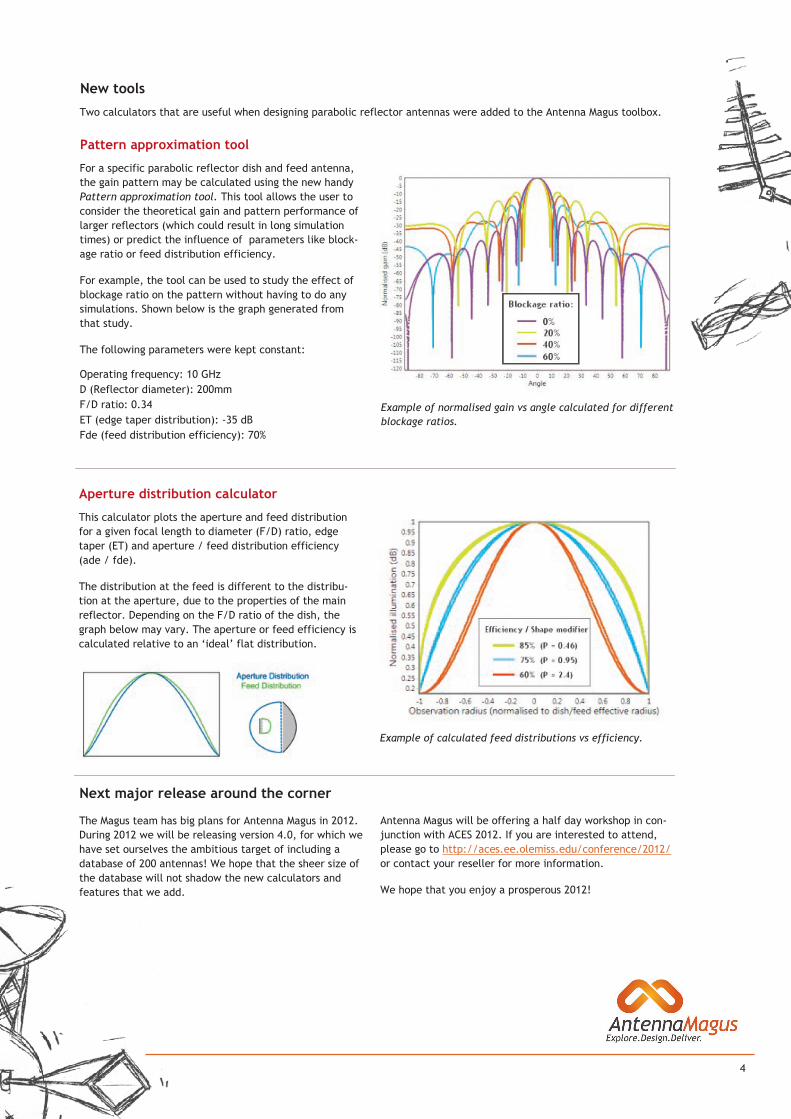
Example of normalised gain vs angle calculated for different
blockage ratios.
For a specific parabolic reflector dish and feed antenna,
the gain pattern may be calculated using the new handy
Pattern approximation tool. This tool allows the user to
consider the theoretical gain and pattern performance of
larger reflectors (which could result in long simulation
times) or predict the influence of parameters like block-
age ratio or feed distribution efficiency.
For example, the tool can be used to study the effect of
blockage ratio on the pattern without having to do any
simulations. Shown below is the graph generated from
that study.
The following parameters were kept constant:
Operating frequency: 10 GHz
D (Reflector diameter): 200mm
F/D ratio: 0.34
ET (edge taper distribution): -35 dB
Fde (feed distribution efficiency): 70%
New tools
Two calculators that are useful when designing parabolic reflector antennas were added to the Antenna Magus toolbox.
Pattern approximation tool
Example of calculated feed distributions vs efficiency.
This calculator plots the aperture and feed distribution
for a given focal length to diameter (F/D) ratio, edge
taper (ET) and aperture / feed distribution efficiency
(ade / fde).
The distribution at the feed is different to the distribu-
tion at the aperture, due to the properties of the main
reflector. Depending on the F/D ratio of the dish, the
graph below may vary. The aperture or feed efficiency is
calculated relative to an ‘ideal’ flat distribution.
Aperture distribution calculator
Next major release around the corner
Antenna Magus will be offering a half day workshop in con-
junction with ACES 2012. If you are interested to attend,
please go to http://aces.ee.olemiss.edu/conference/2012/
or contact your reseller for more information.
We hope that you enjoy a prosperous 2012!
The Magus team has big plans for Antenna Magus in 2012.
During 2012 we will be releasing version 4.0, for which we
have set ourselves the ambitious target of including a
database of 200 antennas! We hope that the sheer size of
the database will not shadow the new calculators and
features that we add.