News for builders of fast wooden aircraft!
16
August 2006 GP4BFN51 WWW.OSPREYAIRCRAFT.COM The prototype GP-4 uses a manual landing gear retraction system. After numerous re- peated requests from builders, George devel- oped an electric hy- draulic gear for the GP- 4. The advantages of the hydraulic system are obvious, flip a switch and fly the airplane. The disadvantages in- clude extra weight, possible electric/ hydraulic failure, a back-up system, and maybe some more ex- pense. No machine work is required for any of the components. Plans are available for $150 from Osprey Aircraft. You can find the address and an order form on the website and on the last page of this news- letter. News for builders of fast wooden aircraft! HYDRAULIC GEAR PLANS NOW AVAILABLE GP-4 Builders & Flyers Newsletter Lynn Sheets’s Awesome GP-4 At Oshkosh 2006
Transcript of News for builders of fast wooden aircraft!

August 2006
GP4BFN51
WWW.OSPREYAIRCRAFT.COM
The prototype GP-4 uses a manual landing gear retraction system. After numerous re-peated requests from builders, George devel-oped an electric hy-draulic gear for the GP-4.
The advantages of the
hydraulic system are obvious, flip a switch and fly the airplane. The disadvantages in-clude extra weight, poss ib le e lect r ic/hydraulic failure, a back-up system, and maybe some more ex-pense.
No machine work is required for any of the components. Plans are available for $150 from Osprey Aircraft. You can find the address and an order form on the website and on the last page of this news-letter.
News for builders of fast wooden aircraft!
HYDRAULIC GEAR PLANS NOW AVAILABLE
GP-4 Builders & Flyers Newsletter
Lynn Sheets’s Awesome GP-4 At Oshkosh 2006

simple enough, however the ad-dition of augmenting springs, air driven up-locks, and door link-age adds complexity as the de-sign evolved. It does work well and has been trouble free for the past 900 hours. If your memory is working, the manual system is fail safe. The FAA does not require any emer-gency back up in a manual sys-tem. If only linkage works the gear up and down, they equate it the same as any control sys-tem. One of the peculiarities of the GP-4 manual system is the faster you go, the more muscle it takes to retract. This is due to the shape of the main gear doors. They form a low pres-sure area on the curved outer surface. I have flown the GP-4 without the doors and the gear retracts as easily as when the plane is setting on jacks. Speeds much over 105 mph in-hibits gear retraction. The GP-4 gets off about 90 mph and accelerates rapidly. Once you learn the throw of the retract handle it is easy to retract the
Fellow GP-4 Builders:
The fact that there are two types of retractable gear available for the GP-4 sometimes presents a dilemma for new plan holders. It's often the question; should I go hydraulic or stick with the manual system? I will try to give you my best analysis of the two systems and the genesis behind each design. When I designed the manual system for the GP-4, I had used it successfully on the Osprey 2. I was also influenced by a 1966 Mooney that I purchased in 1967. I had to muscle the Mooney gear to get it up, but the absence of motors and hy-draulics was appealing.
The GP-4 gear geometry shown on drawing #33 (top left) seems
P A G E 2
George’s Corner By george Pere ira
Caption describing picture or graphic.
A U G U S T 2 0 0 6
...the absence of motors and hydraulics was
appealing.
gear before you get to 100 mph. I suggest on first flights to leave the gear down until you are at traffic altitude, then slow to 100 mph and get comfortable flying at the lower air speed. Now you can retract the gear. Keep doing this until the throw be-comes easier, and there is no bobble from any control re-sponse during retraction. Remember, if you don't get the gear up on the first try after lift off, leave it alone and just fly the airplane. When you're at a safe altitude slow up and retract at a safe airspeed. When car-rying a passenger, be sure there is no clothing or body parts covering the retract recep-tacle. I once punched a hole through my passenger's leather coat. His four letter expletive still rings in my ears. The gear handle doesn't take up much room once stowed in the gear up position. In the down position, it sets about four inches in front of the avionics. To get the radio out of the tray, you have to retract. This is no big deal but it pays to have some custom jack stands for your annuals. I designed the hydraulic gear for the GP-4 because several builders had asked for an alter-nate retraction system. A local GP-4 builder, Jake Jackson, had involved my good friend Ralph Hallenborg in retrofitting a hydraulic gear in his almost finished GP-4. Between the three of us we got a hydraulic

inch. Anyone starting to build who has not made up his mind on which set up he wants, has to make these modifications before he gets too far. The nose gear tunnel has addi-tional mount blocks over the manual gear. The main gear is moved outboard one inch, so all of the gear mount plates are in a different location. As for the cost, the hydraulic gear will cost more. The three hydraulic cylinders will cost around $150 each. The pump motor is about $400. You have a bunch of hoses to make up, so I recommend you buy a mandrel and make up your hoses. The hydraulic gear eliminates the retracting push rods and the complex gear handle, walking beam component. The advantage of the hydraulics is obvious. Flip a switch and fly the plane. The manual system works OK and will save you a few bucks. Weight wise, I esti-
mate the hydrau-lics will cost you about six pounds. If you have fur-ther questions, give me a call. Regards to all, George
gear set up that has served Jake well over the years. I was looking for a design much less complex than Jake's hy-draulic gear. I wanted some-thing that didn't require expen-sive machine work, and could use available hydraulic compo-nents. It took me a year to re-search plus a couple of working mock ups to get what I wanted. Number one, it had to be builder fabrication friendly. Number two, it needed fail safe up-locks so the hydraulics could be shut down. Number three, it had to have an emergency gear down release, exclusive of electric or hydraulic power. This is also a require-ment from the FAA on experi-mental aircraft. The hydraulic gear spaces the main gear one inch further out-board. This allows the GP-4 to set a little more tail high since the gear legs are extended one
P A G E 3 G P - 4 B U I L D E R S & F L Y E R S N E W S L E T T E R
George’s Corner
Many GP-4 builders who have completed their fuselage have installed Jim Weir’s antenna kit. Jim has many more “can’t live without” electronic designs that will save you beaucoup bucks or as he says, “A champagne panel on a beer budget.” He has published a full panels’ worth of designs in Kitplanes for several years, from about 1996 to present. I have listed all the publications and subject that I have, perhaps someone else could fill in the blanks
Kitplanes Magazine Jan 97, pg 87, Coaxial cable
Mar 97, pg 69, Extending landing light life
May 97, pg 72, ELT antenna
July 97, pg 79, Wire rack
Oct 97, pg 62, Radio Connectors
Feb 98, g 86, Radio “stuff”
Apr 98, pg 20, Altitude chamber
June 98, pg 86, Auto Am FM Radio
Oct 98, pg 60, Inexpensive intercom
(I missed most of 1999 & 2000)
Dec 99, pg 115, VHF nav antenna
Oct 00, pg 49, LED position lights
Nov 00, pg 65, GPS
Jan 01, pg 88, Dim Bulbs
Feb 01, pg 61, Antennas
Apr 01, pg 61, lamp dimmer
Aug 01, pg 68, Aviation software
Feb 02, pg 43, Engine monitor
Apr 02, pg 79, Battery sulfate buster
BUILDER’S RESOURCE BY BOB FOSTER

Right Fuselage – No damage, check canopy for free movement Right Static Port – Unob structed
Right Wing and Control Sur face Skins – No damage Right Flap and Aileron Attach Points – Check Right Aileron – Check, free movement Right Nav/Strobe Light – Check Right Fuel Tank Vent – Unob- structed Pitot Tube – Remove cover, unobstructed Right Fuel Tank – Check fuel quantity, fuel cap secure Right Landing Gear and Doors – Check (no damage, brake pad wear, brake assembly (leaks), remove chocks) Right Wing Tiedown – Release Right Fuel Tank Sump Drain – Drain, check for contami
By Mike Traud In Part One of this series we dis-cussed what it is like to fly a GP-4. In fact, there was no discus-sion on takeoffs or landings, we simply started out at altitude and got an idea as to how this air-craft performs. In this part we’ll discuss what it takes to get a GP-4 to altitude, i.e., preflight, taxi, takeoff and climb. As with any aircraft, the flight starts with a thorough preflight inspection. What follows below is one example of a typical GP-4 Preflight Inspection Checklist. Please keep in mind the fact that your aircraft may and probably will be different. Take a look at the checklist and then we’ll dis-cuss some of the finer points.
GP-4 Pre-flight In-spection Checklist
Magneto/Starter Switch – OFF Master Switch – ON Gear Indicator Lights – Down (Green) Indication Position/Nav/Strobe Lights – Check Fuel Quantity (Center and Main Tanks) – Check Walkaround Inspection Left Static Port – Unobstructed Left Fuselage – No damage, check canopy for free movement Left Elevator – No damage, free movement Tail Tiedown – Release Rudder – No damage Right Elevator – No damage, free movement
nants
Header Tank Sump Drain – Drain, check for contaminants Engine – 6 quarts minimum for flight Right Cowl Fasteners – Check for security and none missing Oil Cooler Louvers – Check, unobstructed Nose Gear – Check condition (strut, doors, linkage), re move chock Air Inlet – Remove cover, un obstructed Alternator Belt – Check Cowl Inlet Ramps – Unob structed Left Cowl Fasteners – Check for security and none missing Fuel Filter Sump Drain – Drain, check for contaminants Left Wing Sump Drain – Drain, check for contaminants Left Wing Tiedown – Release
P A G E 4 A U G U S T 2 0 0 6
Flying the gp-4
Mike Traud preparing to take John Reinhart up for a familiariza-tion flight in Darry Capps’ GP-4, s/n 1. Mike is an 11,500 hour pilot with Master Flight Instructor and FAA Pilot Examiner designations. He has over 200 hours in GP-4’s having flown several and has per-formed numerous checkouts of pilots in the GP-4. He can be reached at [email protected]

over time where upon they should be replaced); the engine cooling inlets (the engine on the GP-4 is very tightly cowled – you don’t want any obstructions such as birds, debris, etc. as this would be a serious impediment to cooling and a fire hazard). When you are looking up into the gear wells, check the attach points of gear to make sure they are absolutely snug and no evi-dence of movement or “play” exists. Check over the weld-ments on the gear trusses, over center struts, rod end bearings, etc. looking for cracks in welds and the overall condition of the structure. (Several GP-4’s have experienced gear “failures” due to excessive side loads during crosswind landings or simply not keeping the machine straight when touching down. A few of these type landings and some-thing typically lets go and you’ve crunched your a i rp lane. (Bummer.) Over time, as the
Left Landing Gear and Doors - Check (no damage, brake pad wear, brake assembly (leaks), remove chocks) Left Fuel Tank - Check fuel quantity, fuel cap secure Left Fuel Tank Vent – Unob structed Left Nav/Strobe Light – Check Left Aileron – Check, free movement Left Flap and Aileron Attach Points – Check Left Wing and Control Surface Skins – No Damage
Master Switch—Off
As you can see from the above Preflight Inspection Checklist, the procedure is straight for-ward. Some particular details regarding the GP-4 to pay atten-tion to are the gear doors (inadvertently extending the gear above the design extension speed could result in stress on the doors – ref. GP4BFN 48; August 2005; page 3 for a re-view of GP-4 speed limitations); the canopy latch mechanism (you want this checked for firm, positive latching); the cowl fas-teners (some tend to loosen up
aircraft ages, you may notice some cracks or blemishes in paint (especially around faring areas and locations where flex-ing occurs in the structure). While these are typically of no concern (except in the appear-ance area), they should be kept track of and investigated further if the crack or blemish increases in size. After a thorough preflight inspec-tion, its time to get in and start it up. (Do you have the required fuel load for the intended flight?) I’m not going to tell you how to get into the GP-4 – it is some-what small and requires a bit of flexing. (The procedure to assist an attractive female into the GP-4 cockpit, while very complex, can add to the overall enjoyment of the flying experience. Be sure to assist her first, then you get in.) Once you are secure in the sad-dle, take a minute or two to relax and look around the cockpit. In most cases, the plane your sit-ting in is the one you built and as such, it should fit like a glove. George Pereira designed the cockpit and instrument panel layout using very conventional, tried and true methods so the familiarity of it all should be very comfortable. Make sure your passenger (if applicable) is set-tled in with seat belt/shoulder harness fastened and comfort-able. Explain the procedure to unlatch the canopy (should that be required), the use of the headset and that they are going
P A G E 5
Flying the gp-4
P A G E 5 G P - 4 B U I L D E R S & F L Y E R S N E W S L E T T E R

of and engine driven or electric boost pump failure during take-off. The discussion below for engine starting deals with the Lycoming IO-360 series engines. These are four cylinder, horizontally opposed, aircooled, direct drive 200 horse power engines and are built-proof in their design. The 360 series is a perfect match for the GP-4 and provides an abundance of performance that leaves the competition in your mirrors. The following checklists are typical for engine starting of the IO-360 series:
Engine Start
Checklist – Cold Engine
Seat Belts/Shoulder Harness – Secure left and right
flying in an experimental aircraft. Now lets run the Before Starting Checklist:
Before Starting Checklist
Preflight Inspection -- Complete Fuel Quantity – Check, Center Tank, Left and Right Main Tanks ELT – Armed
Seat Belt/Shoulder Harness – Secure left and right
Fuel Selector – Center Tank for takeoff
Parking Brake – Off
Magneto/Electronic Ignition / Starter Switch – Off
Master Switch – Off
Alternator Switch - Off
Alternate Air Door – Pull to open
Mixture – Idle/Cutoff
Propeller – Forward
Throttle – Closed
Panel Switches – Off
Circuit Breakers – Check
Passenger Briefing – Complete
As with the Preflight Inspection Checklist above, the Before Starting Checklist is provided as an example and may not fit the requirements for you aircraft. It should be noted at this juncture the fuel selector design in the GP-4. George’s design incorpo-rates a four (4) position (Off, Left, Center, Right) fuel selector. Because the center fuel tank is above the wing tanks in terms height above the mean center of the airframe, it has gravity feed characteristics. Selecting the center tank for takeoff provides and added safety margin in case
Brakes – Set
Circuit Breakers – Check
Throttle – 1/8 to ¼ inch open
Propeller – Forward
Mixture – Idle cutoff
Master Switch – On
Beacon/Nav Lights – On, as required
Auxiliary Fuel Pump – On
Mixture – Advance to full rich until fuel flow registers (usually 3 seconds), then idle cutoff
Auxiliary Fuel Pump – Off
Propeller – Clear area
Starter – Engage, as engine starts, advance Mixture to full rich
Throttle – 1000 RPM
Oil Pressure – Rising to 60 PSI
Fuel Pressure – Check 10 –15 PSI
Suction – 4.8 to 5.2 in Hg
Alternator – On
Ammeter – Charge indication
Avionics Master Switch – On
Trim – Set for takeoff
Flying the gp-4
P A G E 6 A U G U S T 2 0 0 6
3 headed for Oshkosh

ning, switch on the electronic ignition. (If you a have dual electronic ignition installation, follow the prescribed procedure from the manufacturer for en-gine starting.) Occasionally, an engine may become flooded during the start procedure. The following checklist addresses a flooded engine:
Flooded En-gine, Clear and Start Checklist
Mixture – Idle cutoff
Throttle – Full open
Propeller – Clear
Starter – Engage and count six propel ler blades of rotation, then starter disengage
Wait – 1 to 2 minutes
Throttle – 1/8 inch open
Mixture – Idle cutoff
Starter – Engage, as engine starts ad
Engine Start
Checklist – Hot Engine
Seat Belts/Shoulder Harness – Secure left and right
Brakes – Set
Circuit Breakers – Check
Throttle – 1/8 to ¼ inch open
Propeller – Forward
Mixture – Full rich
Master Switch – On
Beacon/Nav Lights – On, as required
Auxiliary Fuel Pump – Off
Propeller – Clear area
Starter – Engage
Throttle – 1000 RPM
Oil Pressure – Rising to 60 PSI
Fuel Pressure – Check 10 –15 PSI
Suction – 4.8 to 5.2 in Hg
Alternator – On
Ammeter – Charge indication
Avionics Master Switch – On
Trim – Set for takeoff
The above checklists are identi-cal for the start procedures ex-cept that for a hot engine, the initial priming (utilizing the auxil-iary fuel pump) is omitted and the mixture control is set to the full rich position. These proce-dures are fairly standard for Ly-coming fuel injected engines util-izing two magnetos. Some en-gine installations may have elec-tronic ignition on one side and a standard magneto on the other. Typically, starting these engines is identical, except that you usu-ally start the engine on the mag-neto and once the engine is run-
vance Mixture to full rich
Throttle – 1000 RPM
Oil Pressure – Rising to 60 PSI
Fuel Pressure – Check 10 –15 PSI
Suction – 4.8 to 5.2 in Hg
Alternator – On
Ammeter – Charge indication
Avionics Master Switch – On
Trim – Set for takeoff
The above procedure should be repeated if the engine does not start. You may have to turn on the auxiliary fuel pump and ad-vance the mixture for 1 second to re-prime the engine. It is im-portant to emphasize here that the above procedures are for standard IO-360 installations. Many GP-4’s have fairly stan-dard engine installations, how-ever there usually exists minor differences such as electronic ignition. These differences are taken into account with varia-tions in the above engine start-ing checklists.
Flying the gp-4
P A G E 7 A U G U S T 2 0 0 6
George and Pat Salamone

nicely responsive. On hot days, you will want the canopy open. The GP-4 canopy design is such that the canopy is prone to slide shut due to the 11 degree slope of the canopy base. To solve this problem, I have installed a “canopy friction” device which utilizes a threaded knob with a pad on the lower side which, when turned to a certain point, contacts the canopy base and slows or stops the sliding action of the canopy. (Refer to GP4BFN 49, January 2006 for some ideas on completing your canopy such as the friction knob.) As you approach the run-up area, be aware of other aircraft in the same area and be sure to note which way you are pointing (generally into the wind) so the propeller blast doesn’t piss any body off. Also be aware of your strobe lights dur-ing night operations. Now lets run the Before Takeoff Check-list:
As the engine settles in and all parameters are within limits (i.e. the green arc on temperatures and pressures), you are ready to taxi for takeoff. Take a minute or two to run a Before Taxi Checklist:
Before Taxi Checklist
Radios – Tune to appropriate ATIS, ASOS, AWOS frequency (if avail able) for current airport conditions
Transponder – Standby
Beacon/Nav/Strobe Lights – As re quired
Navigation Systems – Set
Altimeter – Set
With regards to navigation sys-tems, this is where several dif-ferences between cockpit lay-outs exists among GP-4s. Be-fore taxing, ensure your particu-lar system is set for the intended flight (i.e. directional gyro – set to magnetic compass; GPS sys-tem – on and integrity checked, flight plan loaded, etc.). Check the brakes as you initiate the taxi and make sure you have an airport diagram out if you’re even the slightest bit unfamiliar with the airport. (It is always a good idea to have the airport diagram out either way….) As you taxi the GP-4, you’ll no-tice that it has very good ground handling characteristics. Visibil-ity forward is very good with no significant obstruction. Nose wheel steering is accomplished using the rudder pedals and is
Before Take-off Check-
list
Brakes – Set
Fuel Selector – Center Tank, recheck quantity for intended flight
Auxiliary Fuel Pump – Off
Flight Controls – Check, free and cor rect
Flight Instruments – Check
Radios and Navigation Equipment – Check and set for departure
Alternate Air Door – Pull to open
Trim – Set for takeoff
Mixture – Full rich
Throttle – 1900 RPM
Magneto(s) – Check, no more than 175 RPM drop
Propeller – Cycle three times noting RPM drop, manifold pressure rise, oil pressure drop
Suction – Check
Throttle – 1000 RPM
Canopy – Closed and confirmed posi tively latched
Seat Belts/Shoulder Harness – Secure left and right
Flying the gp-4
P A G E 8 A U G U S T 2 0 0 6
Always draws a crowd

Takeoff procedure with manual gear
system
As with any takeoff, be sure to clear the area thoroughly before taking the runway. As you taxi onto the runway, recheck the fuel selector, canopy and take a quick look around the cockpit to ensure everything is in order. (It’s a little late if she now says she wants to get out……). Line up on the centerline of the run-way and smoothly add power, checking temps and pressures as you bring it through 2000 RPM. (Note: Avoid rapid open-ing of the throttle as the engine [IO-360 series] is equipped with a counterweighted crankshaft which could be subjected to de-tuning of the counterweights which in turn could result in damage to the engine.) Release the brakes and note that some right rudder will be
Transponder – On/Alt
Auxiliary Fuel Pump – On
During the run-up procedure, pay particular attention to the magneto check. If a drop of more than 175 RPM occurs, plug fowling may be the culprit or possibly faulty wiring. In some cases, you may have to return to the hangar for further investigation.
Now the fun begins. You are ready for takeoff. Since GP-4s can be built with either a manual gear system or an electric/hydraulic system and since there exist many operational and flight handling differences be-tween the two, both takeoff pro-cedures will be discussed.
Takeoff Checklist (Normal Takeoff)
Auxiliary Fuel Pump – Off
Alternate Air Door – Pull to open
Power - Advance Throttle SLOWLY to full and 2700 RPM
Nose Wheel Lift-Off – 60 knots (ease back on the stick – not abrupt – until aircraft becomes airborne and at tains 10 degree climb attitude)
Landing Gear – Retract before 100 knots
Climb – Establish good rate of climb (at or below 110 knots) to 1000 AGL
needed to track the centerline. You may be surprised as to how much right rudder is needed here. Remember P-factor? What about spiraling slipstream? Or torque. To save you the staggering amount of time it takes to find this information in the FAA Flying Handbook, we’ll go through a brief explanation of the factors which want to take you off the runway to the left. P-factor is a yawing moment or force which acts upon the air-craft as a result of the downward propeller blade taking more of a bite than the upward blade. This is because the angle of attack of the downward blade is greater than the upward blade. A nice way to see this is when a GP-4 is parked, it usually sits a little tail low. With the propeller blades horizontal, sight down the leading edge of the wing and note the bite of each propeller blade. You will notice the down-ward blade definitely has the bigger bite. This is what is oc-curring when you are careening down the runway. The large bite
Flying the gp-4
P A G E 9 A U G U S T 2 0 0 6

and in one continuous motion, moving the gear handle through approximately 90 degrees of travel aft to the horizontal (gear retracted) position between the seats. You need a little muscle to do this. You also need to take your right hand off the throttle to do this. And you have to maintain con-trol of the aircraft with your left hand in the process. Remember the discussion of pitch sensitivity in Part One of this discourse? (ref – GP4BFN 50, May 2006). We discussed how sensitive the aircraft is especially in pitch. This is where deftness and skill come in as you don’t want to inadvertently pull back on the stick during gear retraction and depart the GP-4 from controlled flight (i.e. a stalled condition). This has occurred before in this aircraft with fatal results. It is natural for you to pull back on the stick as you are moving the gear handle aft to retract the
produces more thrust and wants to yaw the machine to the left. Right rudder keeps you straight. Spiraling slipstream is another force that wants to yaw you to-wards the right. As the propeller turns, the slipstream it generates rotates in a clockwise direction around the fuselage. As it ro-tates clockwise, it strikes the vertical stabilizer and “pushes” the tail to the right, nose left, which requires right rudder to keep you straight. Spiraling slip-stream is most pronounced dur-ing the initial takeoff roll. Torque (or reactive torque) forces occur when either the en-gine tries to rotate the propeller or the propeller tries to rotate the engine. These forces are trans-mitted to the engine itself, the engine mount and finally the air-frame. Torque forces are easily corrected with application of rud-der. As the GP-4 accelerates through 60 knots, smoothly lift the nose wheel with slight back pressure on the stick. Hold the back pressure – not abrupt – and lift-off will occur at about 70 knots. Retract the gear at or below 100 knots. This is an area of GP-4 flight technique that deserves men-tion. The manual gear system design requires that you retract the gear with your right arm (assuming that you are in the left seat). This involves grabbing the gear handle, moving it down to release it from the vertical (gear extended) position lock,
gear. It takes a bit of practice to get this down where you can immediately retract the gear af-ter liftoff. Until you are very adept at this procedure, simply climb out at 100 knots until you get to a safe altitude and then retract the gear. You will need to reduce power to keep the machine from exceeding 100 knots in order to retract the gear. The faster you go, the more difficult it is to get the gear up because of the aero-dynamic loads imposed on the gear. Be careful when you latch the gear retract handle in the hori-zontal (gear retracted) position as it can get hung up in you pas-sengers clothes (i.e. jacket or sweater) or cords for head sets. If something gets in the way, you won’t be able to fully retract the gear and close the inner doors via the air pump (which is enabled by the gear handle be-ing in the full latched, horizontal
Flying the gp-4
P A G E 1 0 A U G U S T 2 0 0 6

erably slower than the manual system (depending on the sys-tem pressure in your aircraft). Note: The system pressure is set by the pump manufacture and varies depending on the pump and its configuration. When ordering your gear pump, you can specify what system pressure you want. Typical hy-draulic gear pressures for light aircraft range from 800 psi to as high as 1800 psi. As such, it is important to ensure all three wheels are up and locked before settling into the climb. Now that we have the aircraft configured for the climb, we can initiate the Climb Checklist.
Climb Checklist (Normal)
Throttle – 25” manifold pressure
position. With the gear re-tracted, we can now settle into the climb portion of the flight. As mentioned in the Takeoff Check-list (Normal Takeoff), it is a good idea to climb initially at (or be-low) 110 knots to gain altitude so that a safe return can be initi-ated is a problem is encountered during this phase of flight. (This is simply a safe practice in any aircraft which provides you needed altitude for maneuvering in case of engine problems or other issues which would dictate an immediate return to the air-port.)
Takeoff procedure with electr ic /
hydraul ic system There are some differences in the takeoff procedure with GP-4’s equipped with the electric/hydraulic gear system. Essentially, the above procedure (manual gear) is followed and the gear is retracted using the switch in the cockpit. As with the manual gear system, it is important not exceed the design retraction speed limitation of 100 knots. This could impose a load on the hydraulic system which could result in the gear not reaching the up and locked posi-tion. Remember, the GP-4 acceler-ates rapidly and you’ll see your-self through that 100 knot limita-tion before you know it. Another consideration with the electric/hydraulic system is the retrac-tion time. This can be consid-
Propeller – 2500 RPM Mixture – Rich Airspeed – Establish: Vy (best rate): 125 knots; Vx (best angle): 95 knots Alternate Air Door – Close and engage ram air inlet Auxiliary Fuel Pump – Off, note fuel pressure Temperatures and Pressures – Monitor (Oil, Fuel, CHT) The climb airspeeds stated in the above checklists may vary, depending on your aircraft and it’s performance as determined during the test phase. They are provided here as reference speeds and may not match what you see in your GP-4. As you climb, pay attention to engine temperatures (i.e., oil tempera-ture, fuel pressure, and CHT). If you see higher than normal temps during the climb, you may have a cooling problem. Warmer temperatures can be
Flying the gp-4
P A G E 1 1 A U G U S T 2 0 0 6

The GP-4 is equipped with an alternate air source which pro-vides induction air other than that provide from the ram air inlet. This procedure is utilized on takeoff to minimize debris and FOD (Foreign Object Dam-age) entering the ram air inlet while on the ground.
mitigated by reducing the climb rate, enriching the fuel mixture or reducing power. In any case, you may consider returning to the airport to check into the problem. The checklist above as well as the Takeoff Checklist address the Alternate Air Door.
In the next installment of this series, we will discuss the de-scent and landing of the GP-4. To further discuss takeoff’s in the GP-4, or any other subjects, feel free to contact me at the G o l d R i v e r F a c i l i t y : [email protected]
Flying the gp-4
P A G E 1 2 A U G U S T 2 0 0 6
The GP-4 Rotisserie
want it to happen now and you can’t find an instant helper. I decided that once the fuselage had it’s top skin on, I would con-
struct a rotisserie to support the fuselage so that I could turn it to any position I required, when I wanted and without any assistance. By chance, I came across a couple of heavy duty tripod stands at a local sec-
By Adrian McClelland There is a stage in building the fuselage when it needs to be turned over, on it’s side, upside down, right side up again, etc..
Every time you want to do this, you have to enlist the help of someone for assistance, which can be a bit inconvenient if you
ond hand dealer. These were adjustable for height. I welded section of 1 ½” steam pipe across the top of the stands. Then I welded up a cou-ple of frames that would clamp to the firewall and Sta.178, welded a length of pipe to them that would fit inside the steam-pipe. A couple of 7/16” nuts welded to the steampipe and a couple of bolts to fit is all that was needed to hold the fuselage in any required position.

I screwed some wood formers to the support frames that fitted inside the firewall and sta.178 voids to overcome any slippage problems. My fuselage can now be turned with one finger. It actually works better than I anticipated. The best part of all, the whole thing cost me about $10.00. Hope you guys find this useful. Anyone with “SKYPE” can skype my as adriansgp4 and I’ll show you live on the webcam. Adrian McClelland Victoria Australia
The gp-4 rotisserie
P A G E 1 3 A U G U S T 2 0 0 6

P A G E 1 4 A U G U S T 2 0 0 6
Adrian’s
Rotisserie
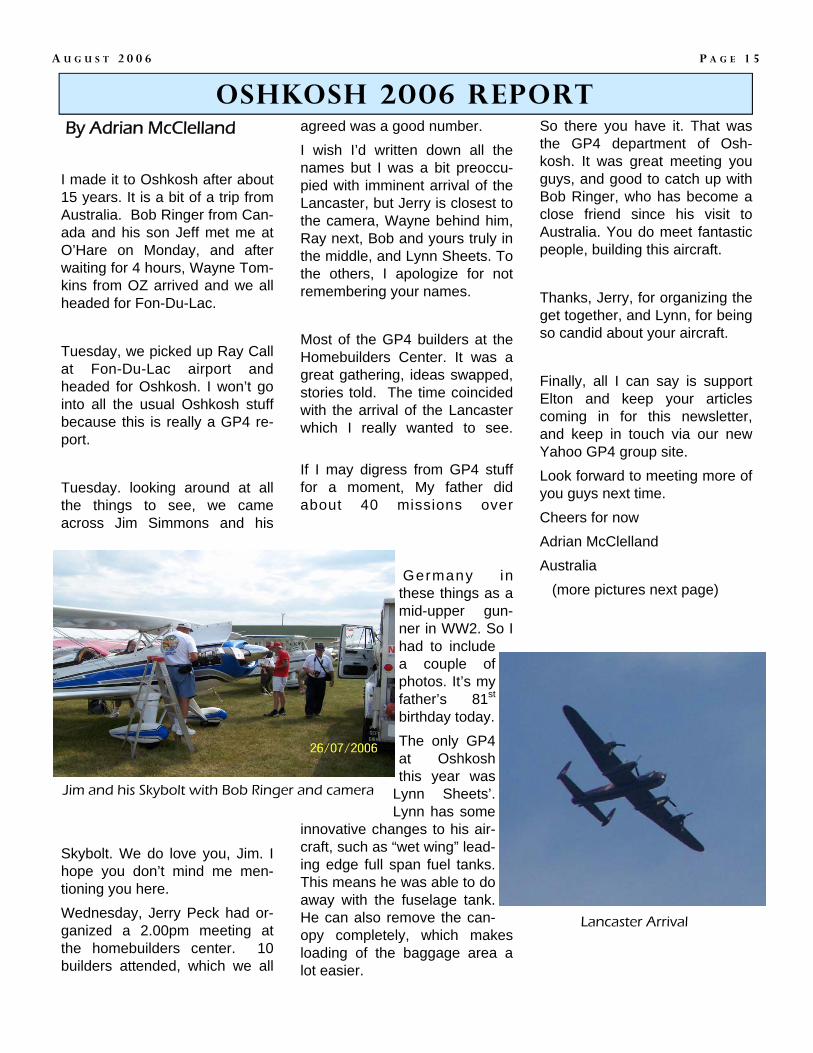
agreed was a good number. I wish I’d written down all the names but I was a bit preoccu-pied with imminent arrival of the Lancaster, but Jerry is closest to the camera, Wayne behind him, Ray next, Bob and yours truly in the middle, and Lynn Sheets. To the others, I apologize for not remembering your names. Most of the GP4 builders at the Homebuilders Center. It was a great gathering, ideas swapped, stories told. The time coincided with the arrival of the Lancaster which I really wanted to see. If I may digress from GP4 stuff for a moment, My father did about 40 missions over
Germany in these things as a mid-upper gun-ner in WW2. So I had to include a couple of photos. It’s my father’s 81st birthday today. The only GP4 at Oshkosh this year was
Lynn Sheets’. Lynn has some
innovative changes to his air-craft, such as “wet wing” lead-ing edge full span fuel tanks. This means he was able to do away with the fuselage tank. He can also remove the can-opy completely, which makes loading of the baggage area a lot easier.
By Adrian McClelland
I made it to Oshkosh after about 15 years. It is a bit of a trip from Australia. Bob Ringer from Can-ada and his son Jeff met me at O’Hare on Monday, and after waiting for 4 hours, Wayne Tom-kins from OZ arrived and we all headed for Fon-Du-Lac. Tuesday, we picked up Ray Call at Fon-Du-Lac airport and headed for Oshkosh. I won’t go into all the usual Oshkosh stuff because this is really a GP4 re-port. Tuesday. looking around at all the things to see, we came across Jim Simmons and his
Skybolt. We do love you, Jim. I hope you don’t mind me men-tioning you here. Wednesday, Jerry Peck had or-ganized a 2.00pm meeting at the homebuilders center. 10 builders attended, which we all
So there you have it. That was the GP4 department of Osh-kosh. It was great meeting you guys, and good to catch up with Bob Ringer, who has become a close friend since his visit to Australia. You do meet fantastic people, building this aircraft. Thanks, Jerry, for organizing the get together, and Lynn, for being so candid about your aircraft. Finally, all I can say is support Elton and keep your articles coming in for this newsletter, and keep in touch via our new Yahoo GP4 group site. Look forward to meeting more of you guys next time. Cheers for now Adrian McClelland Australia (more pictures next page)
Oshkosh 2006 report
P A G E 1 5 A U G U S T 2 0 0 6
Jim and his Skybolt with Bob Ringer and camera
Lancaster Arrival