Newport News Shipbuilding Company Interview re Ship Design … · 2012-03-14 · Newport News...
22
Newport News Shipbuilding Company Interview re Ship Design Process November 20, 1995 TR96-002 January 1995 Fred Brooks with Kenton Meland's and Dinesh Manocha's corrections Department of Computer Science CB #3175, Sitterson Hall UNC-Chapel Hill Chapel Hill, NC 27599-3175 This work was supported by ARPA Contract No. DABT63-93-C-0048 UNC is an Equal Opportunity/Affirmative Action Institution.
Transcript of Newport News Shipbuilding Company Interview re Ship Design … · 2012-03-14 · Newport News...
Newport News Shipbuilding Company
Interview re Ship Design Process
November 20, 1995
TR96-002 January 1995
Fred Brooks
with Kenton Meland's and Dinesh Manocha's corrections
Department of Computer Science CB #3175, Sitterson Hall UNC-Chapel Hill Chapel Hill, NC 27599-3175
This work was supported by ARPA Contract No. DABT63-93-C-0048
UNC is an Equal Opportunity/Affirmative Action Institution.

Newport News Shipbuilding Company
Interview re Ship Design Process, November 20, 1995 Fred Brooks, with Kenton Meland's and Dinesh Manocha's corrections
1. Highlights and Surprises(*)
1.1. *Design is mostly architectural, not mechanical. It consists mostly of arrangement and connection of equipment.
1.2. The design process is top-down, consisting of preliminary design and naval architecture, contract design, gross equipment placement, and detailed design.
1.3. Several disciplines within design and planning-NNS believe it is important to have all disciplines in the same design/manufacturing system.
• Naval architecture of whole vessel • Hull • Structure • Major equipment • Piping • Ventilation • Wireways and cables • Logistics and maintainability
1.4. Four types of detailed design tasks: • Specifying parts to be made from standard stock to custom dimensions • Selecting from a parts catalog, which for Double Eagle is 18,000 parts, some made by NNS, most purchased • Specifyiog parts to be made by parameterization of standard designs, mostly pipe • Arrangement of parts as to what goes where
1.5. Visualization can be useful at many stages in the process, e.g., hull design, computational fluid dynamics, and arrangement, but it is not necessarily what they need most.
1.6. The standard SBD problem was presented by Chel as occurring in preliminary and contract design, where major design alternatives are explored. At this level, the biggest bottleneck is not physical arrangement or its visualization, but the CFD analyses of hull/powerplant combinations (10 minutes·4 hours, depending upon level of fidelity of the simulation, not of the visualization).
1.7. Although the designers think interactive walkthrough would be useful for outfitting and arrangement, nobody listed it among their dream tools.
1.8. *Piping is the largest single design task in terms of effort. On naval vessels, it is more than a third of the whole arrangements task. On commercial vessels, structures loom larger, so piping is perhaps 15-20%.
1.9. *Designers rarely move bulkheads or otherwise manipulate structure, except for holes, hangers, attachment points, etc.
"The consequences of such major moves tend to cycle into larger problems."
2 1.10. *During the Seawolf design, NNS moved from drawings as the primary design document to a computer model, from which drawings are taken off. The workplan for the Seawolf required a full· scale wooden mockup for design verification.
1.11. *Late the in the design, NNS sought and received Navy approval to abandon the mockup.
Tatum, S.A., J.C. Byrum, and P.W. Rourke, "Design validation using computer models in lieu of fullscale mockups," Marine Technology, 31, 3 (July, 1994) 225-230. Mrs. Ward has a copy of the issue.
1.12. *No American shipbuilder has sold a commercial vessel for export since 1957; NNS is trying to get back into the commercial ship business. Hence designing for low cost is a life-or-death objective.
1.13. Most designs start with an existing ship as a model
For the new Double Eagle product line, NNS designers studied existing tankers owned by customers, etc.
1.14. Preliminary design and hull design are heavily supported by analysis programs, mostly in FORTRAN, most purchased.
1.15. *Models are kept as a high-level, feature-based representation. A derived representation is used and cached, made up of CSG trees, (unions, negations, no intersections). It is tessellated on the fly.
1.16. *Close collaboration among designers, even though closely collocated, is rare after preliminary design. Remote collaboration is not wanted.
When competition for a bit of space occurs, the designer who created the foul is responsible for resolving it, by negotiation with the one who got into the space first, and, if necessary, by appeal to the Space King. The CAD system clearly identifies fouls and their perpetrators.
The close collocation, however, means that designers typically know what the designers working in the same space are working on.
1.17. A major bottleneck in the design schedule is getting parts catalog component drawings from the vendors and converting them to coarse exterior 3-D models.
1.18. *Models are relatively small and can be kept on line. The whole Sea wolf model in its native stored format is 6GB. There were about 12,000 primitives in the subset model we saw.
1.19. Most spaces are irregnlar rather than rectangnlar
Besides the curves of the hull, the bulkheads on the Double Eagles are corrugated, to increase their stiffening effect on the whole structure. Bulkheads on naval ships are usually planar.
1.20. *Designers avoid hollow walls or inaccessible spaces.
Walls are made of solid stock with stiffeners, etc. attached to the outside of one surface. Any space that moisture can penetrate needs to be accessible for paint and maintenance.
1.21. Realistic views are of secondary importance, schematic ones with subsystems distinctly colored are of primary importance.
Corollary: realistic illumination and radiosity will have to prove their worth.
But, the computer model is used to verify that the designed illuminants produce the specified illumination levels.

The people with the greatest need for visualization are the Space Kings, followed by individual arrangements designers.
3
For planning, logistics, design verification, and construction planning, eye-in-the-space isometric or VR type views are generated, but at 3-4 seconds/view, with no texture mapping. These people need highperformance visualization. Viewpoint control is awkward for such views, and for orthographic and isometric views as well.
Concerning texture mapping: "The lack of fidelity scares me." [FPB's interpretation: "I don't know what the real product model, from which the ship will be built, contains, if some details are texturemapped onto the visualization."]
Greg Heinrich: "As a Space King, I would use the spatial view if needed to test operational scenarios." David Bennett said that he would definitely use a 3-D spatial view mod if it were available.
Designers normally work with orthographic views, but can switch to isometric. They require very high fidelity display of smaller regions.
Objects are color-coded by subsystem: yellow structure cyan machinery green pipe purple plate part magenta wireways and cable red optional equipment
These colors are determined by the user at plot time, not stored in the catalog.
The hull designer (often singular) has a great need, too, but it is not so much to visualize the hull shape as to visualize the results of the CFD calculations, i.e., the water flowing around the hull.
1.22. *It seems to us that the biggest payoff from SBD is probably available in the Preliminary and Contract phases of the design, when the analysis and simulation changes what ship gets built and how it performs, rather than in Detailed Design and Arrangement, when the potential effect is to reduce design time and cost.
2. The Meeting
2.1. Building 600, NNS, in Newport News, VA
2.2. Monday, November 20, 10:15-4:15
2.3. From NNS, 4101 Washington Ave., Newport News VA 23607 2770
Craig Byrum, Manager, New Product Engineering- Composite Arrangements, E57, 804 688-9879, fax 688-3608
Chel Stromgren, Naval Architect, Research and Concept Development, New Product Engineering, E56, 804 688-7580, fax 688-8828
Kenton E. Meland, NNS SBD Program Manager & CAD/CAM Implementation Supervisor, E40, 804-380-3844, fax 688-1073, [email protected]
Sam A. Tatum, Manager, CAD/CAM Implementation, E40, 804 688-1415
Greg Heinrich, Engineering Supervisor, Fast Frigate Arrangements, Piping, Wireways. Currently a Space King.
4
Rob Spitzer, Engineering Supervisor, Submarine Structural Engineering, E12
Dave Bennett, Information Systems Specialist, CAD/CAM Implementation, E40
2.4. From UNC-CH, Dept. of Computer Science, Sitterson Hall CB#3175, Chapel Hill NC 27599-3175, fax 919 962-1799
Fred Brooks, Kenan Professor of Computer Science, P.I. of UNC SBD and of Walkthrough project, 919 962-1931, [email protected]
Mike Goslin, graduate student, team leader of Walkthrough project, 919 962-1719, [email protected]
Dinesh Manocha, Assistant Professor of Computer Science, Investigator on UNC SBD, P.I. of Nurbs project, 919 962-1749, [email protected]
Subodh Kumar, graduate student, 919 962-1943, [email protected]
2.5. Follow-up plans
UNC to generate and critique this document
NNS to send copies of foils used in presentation. [Attached to this document.]
Plan a two-day meeting in NN on model syntax and semantics
Plan an NNS visit to Chapel Hill
3. The Company
3.1. General description
One of the four disparate divisions of Tenneco
Sales about$ 1.8 billion
About 19,000 people, all in Tidewater. Largest private employer in VA.
A sketch organization chart of the relevant parts was drawn for us, will eventually be appended to this document.
3.2. The Double Eagle (DE) product line of tankers
Four identical ships to be built for international customers Contracts in place; construction began Fall, '95.
Five domestic ships, with same "parallel mid-section" but different front, aft, engines, so eligible for Navy charter. Contract in negotiation.
The domestic tanker is priced at -$ 40 million.
3.3. The Sea wolf experience
Lead design yard for whole submarine, responsible for front half detailed design.
1000 people at peak, 600 average; 10 years, 12 million man-hours, on front half
Acoustic performance a major extra design desideratum
3.4. Other products and activities Carriers Submarines Fast frigate and other naval vessels for foreign sale Landing craft Repair work Complex nuclear overhauls
4. Overview of the Ship Design Process
4.1. Coordinate system: Distance from bow or stern, measured in frame number, and distance from frame, distance from centerline, deck number and height above deck. Alternate is x,y,z. All commercial designs are metric; some Navy contracts, such as Seawolf, Nimitz classes, are British units.
5. Preliminary Design, Commercial Ship
5.1. To answer: Is there a ship such as these specs call for?
5.2. Small, ( -10-person), multi-disciplinary team working closely together
5.3. A few weeks to a few months, governed by contract deadlines
5.4. Starting guesses and analysis cycles
6. Contract Design, Commercial Ship
6.1. To answer: For what price and performance will we contract to build one?
6.2. months, - 20 people
6.3. Settle hull, get performance parameters. Process shown on attached figure:
5
HULL-FORM code and legacy data used to generate first trial hull, which is defined as a set of frames, in wire-frame B-spline form, by HULL-LINES code, which does algorithmic fairing. This produces the hull geometry GDS file.
CALC and SPACES are used for the naval architecture and preliminary allocation of spaces. Weights and their distribution are guessed. This is difficult, and weights are often underestimated. CALC yields rough performance data, so powerplant can be sized and speed estimated. CALC also yields stability metrics, both normal and if compartments are flooded by damage.
MOTION and RESPONSE are calculated. Seakeeping is normally presented to the naval architect as polar-coordinate plots of as many as 30 different metrics for a set of sea states. An example metric might be waves-over-the-deck/hour. Response metrics are typically scalars, such as turningradius/length ratio.
Three to four iterations around the HULL-LINES-Analyses loop are normally made until a feasible hull emerges. As these begin to converge, extensive CFD calculations are performed to check for flow problems (vortices) and to estimate power requirements for target speeds. CFD data is not reliable enough for absolute performance guarantees, but it is good and reliable for differential design. CFD comprehension a hard visualization problem.
On an SGI Crimson, quick CFD (potential flow without free water surface) takes typically 10 minutes. Potential flow with free surface takes perhaps 40 minutes. Viscous flow takes typically four hours.)
6 Creating a post-processed view once the flow is calculated takes a few seconds per view.
Once a hull is satisfactory, HULL-SURF is used to make NURBS patches, using an ACIS surface-fitting package. Half of a Double Eagle hull consists of 20 B-spline patches. comprising 900 panels in the GDS file. This becomes the primary database for the hnll.
From this surface data come the cutting lines for a 1:25 scale styrofoam model, which is tested in a tow tank at a cost of;::; $1 00,000/test. The whole hull design iterates as required from the model tests. Extensive CFD computation enabled DE to converge with only 1 1/2 model test cycles, vs. four for most earlier designs.
From the surface data also come the VIVID® model data and IGES data for fabricating the structure.
6.4. Choose and place large equipment
6.5. Check initial weight distribution guesses, rerun analyses
6.6. Cost estimate, schedule estimate
6.7. Guarantees such as$ 100 K forfeit per 0.1 knot below specified speed.
7. Detailed Design
7.1. To answer: Complete model from which yard can work
7.2. For DE, 12 months, 150 engineers and designers, of whom -35 are into the product model, adding geometry.
7.3. For detailed design: division of team into spaces, then disciplines .
7.4. General arrangements phase: structure plus choose and place catalog equipment, but no outfitting. Usually 1-2 people per space cell rough in all the subsystems of all the specialties.
7.5. Kinds of changes:
Adding additional equipment (and the required foundation, piping, etc. and moving other objects as required)
Substitute one piece of equipment for another
Substitute a new representation of an object, freshly provided by vendor
Analysis calls for new stiffeners or new pipes
Rearrangements for better access during operations or maintenance
Customer-driven changes.
Import a new hull surface andre-trim to it, keeping same topology. This has heavy time and effort costs, so it is rarely performed.
With the domestic DE, tried to make it as a modification of the international DE's "parallel middle body". It turned out that to get it up to target speed it had to be longer and thinner, so a new design was needed. "I lived in the model basin for a month, trying to get it to go faster, but it so compromised the design that we wouldn't offer it to a customer."
7.6. Outfitting phase.: piping, ventilation, wiring, hangers and attachments of all equipment.
There may be a designer on each of 17 piping systems, working in same space.
They may well want to collaborate on a single hanger leg for two parallel runs of pipe from separate systems.
Because the designers are collocated, "you generally know who is working on what" and so formal collaboration and coordination mechanisms are not needed.
7
On the Seawolf, there was a conflict between optimum space arrangements and requirements for combat operations.
The Sea wolf task was made harder because all the combat subsystems were being designed by another team in Syracuse, NY. They communicated by phone, fax, and a coord meeting every month.
Pipes are represented by centerline, cross section, and the nodes of the bends. VIVID® does extensive checking for bend angles, interference, and flange angle matching.
A hole in a bulkhead is defmed as a separate part, with its own centerline and radius. It takes a few seconds to create that part. Then the bulkhead is cut with the hole.
Designers frequently move a component 6" during detailed design, but rarely move the big items or move the little ones far.
8. Organization of the Design Teams
8.1. The Naval Architect does preliminary design, monitors overall ship properties through rest of design process
This monitoring is not architectural supervision nor quality control on later design stages, but just safety checking that nothing done later violates the assumption under which vessel performance and stability were calculated and guaranteed.
8.2. The Space King rules the allocation of space within his domain
8.3. Number of designers
8.4. Training of designers: technical college or apprenticeship program
8.5. Selection of designers: no testing; hire and try for productivity
After training, about 114 to 113 do not perform well and are reassigned to other duties.
There is a correlation between high-productivity and 3-D visualization and navigation capability in designers.
UNC suggestion: NNS might try some spatial visualization tests as part of choosing designer trainees.
9. CAD, the Computer Product Model, and SBD II
9.1. Most of the NNS SBD II and DE managers come from the Sea wolf experience
9.2. NNS is hoping to get a better software design system from the SBD II project, not a tool for use on any particular current design activity.
9.3. CAD is a major cost strategy, to save rework in yard. Old way: design on drawing, then in yard "cut to suit, beat to fit".
8 9.4. VIVID® an arrangement tool built by NNS
A key component is a catalog of some 60 K standard parts.
9.5. Mainframe VIVID®
A 6-processor IBM ES 390 is dedicated to engineering.
million database hits/day on mainframe, of which 2% are design entries, the rest are reads.
The interface was shaped to fit character terminals and PC/DOS approach. It is fairly awkward. It requires 6 months to become fluent. On the demo we saw, the designer had made the demo flow by creating a lot of key-selected macros specific to that demo, to the point of embedding the particular numerical parameters in the macros.
A major database tool; the database intelligence is principally the interfaces for each part: size, shape, connectivity.
The modeler itself has little intelligence.
The database is updated continuously. Space plotfiles are updated every night, so conflicts become visible every day. One engineer can request an update, which takes 5-10 minutes. This happens perhaps 1-2x/week per designer.
The 2-D cursor acts as a laser pointer and yields a list of the 10 objects nearest the viewer that the laser would pass through, in order near-to-far.
The program reserves maintenance access spaces and displays them as transparent objects. The same technique can be used to "grow" parts by a clearance margin to check for near-interferences or for shock envelopes.
In the demo we saw, a pipe was moved. Then the hole in the bulkhead wall for the pipe was moved, using the pipe's geometry.
9.6. Workstation VIVID® is now under development. There is a production version with about 10 users.
WIMP interface should be much easier.
Based on Performer for now.
A portion ofwsVIVID® has been developed as part of SBD.
Structures are most difficult, so they have played with that part.
The piping program has little built-in behavior so far, except that if a node is moved, curve angles at bends are updated, and angle design limit violations are checked and presented. The user can specify end alignment as both position and a vector direction, rather than having to get the next node properly positioned to make the direction proper.
9.7. Seats and equipment
They operate 55 high-end VIVID® seats. (RS-6000), for two shifts. This is a major cost item.
These are supported by a dedicated IBM ES 390 Model 9000-720, with six processors, each at 112 MIPS.
About 23 million hits/day on the database.
Analysis is done on SGI' s
They operate 167 SGI's in engineering, doing analysis and mechanical design of some components, tooling, and gadgets, using SDRC Master Series I-DEAS.
There are about 1200 qualified users of CAD AM, about 400 of VIVID®, and about 300 of I-DEAS
9.8. The naval architect thinks of the model as a collection of spaces; the structures engineer thinks of it as a collection of walls-the same duality one has in buildings.
9.9. The computer model for the DE product line
Fundamentally a high-level feature-based model, and hierarchical, so one can move a subtree as a unit without specifying moves of components.
The catalog of standard parts is based on CSG descriptions.
Multiple independent hierarchies, called product structures, may be superimposed on the one set of design objects.
Example: subsystems over whole ship Example: spatial subdivision Example: Construction and assembly sequence
ws VIVID® has product structures as types.
Fundamentally organized into subsystems, then into spatial cells
All plate objects, including the hull and decks, are defined as molded objects, that is, they are defined by one surface, the mold, and the thickness of the plate.
Cross-linked by two mechanisms: foundation notes (no further description) hole cut requests, linking piping subsystem to structures subsystem
9
9.10. Most vendors supply only 2-D drawings of the catalog parts, so NNS converts these to coarse 3-D models suitable for use in arrangement, essentially one model per catalog entry.
These models have precise interfaces for piping, etc. but only approximate exterior shape, no interior detail at all. A whole engine is represented by -80 CSG primitives. Hence only approximate analyses such as collision detection are possible. We didn't learn what tolerances are allowed in these approximate representations.
They are input as CSG trees, not polys. They don't store the boundaries of CSG objects at all.
How robust is the system that tessellates CSG objects with polys? A: Very.
There is a standard set of CSG primitives, about 18 in number.
There is also a NNS house subset of the standard set especially selected for interactive use.
The conversion took 1-2 people about 10 months for the DE -required additions to the parts catalog, some 18,000 new parts.
9.11. Drawings are taken off the computer model, used by designers and by the yard foreman to actually do the work
Manufacturing makes the most plots.
10 It takes 10-15 seconds to get a drawing plotted.
9.12. *Both the designers and the CAD team were relatively modest and conservative in what they would ask for if given magical technology.
Meland: Quick, cheap access to database. Way to capture as-built model from existing vessels for overhaul and repair. An object-oriented database manager that can handle 20 million parts vs. 300 K today. And better visualization tools for wsVNID®.
Heinrich: Ability to sketch freehand and have things rectified, and then move them with data tablet, vs. keying in object coordinates.
Heinrich: For piping, not only better user input, but also a better geometric system for applying and testing the constraints.
Tatum: Have a good way of capturing design intent, the goals and constraints that the designer has in mind. An easy ways to change object classes in the existing database structure-it takes weeks.
Stromgren: Faster analysis tools so can quickly explore more alternatives. during the Preliminary/Contract design phases. [Note that this is today the analysis-based part of the design and so is readiest to go on to simulationbased design.]
A tool for the more accurate preliminary determination of weights and weight distribution based on old designs and estimates of new key data.
9.13. Major problems today:
Need quick, cheap access to the database
Cost per seat, so too few seats. An RS-6000 seat costs$ 20K, plus 100 hours training on VMD®, not counting the database server capacity to support it. UNC team suggested NNS look at Linux on Pentium machines
Contention and concurrency control
Revision control and tracking
10. Implications for UNC SBD Work Plan
10.1. On course: relevant and supported
Level of detail
Polygonal simplification
Visibility - portals
CSG and NURBS
Model clean-up; but shift emphasis to CSG primitives from polys
10.2. Relevant but unsupported, activities underway
Mine's 3-D interaction technology Ideal includes automatic layout, or at least rectification of piping, etc. runs
Cue-ball for steering viewpoint. "Worlds in miniature" seems very promising for this application. 3-D cursors, widgets
Weber's wayfmding, especially for rooms full of pipes and ventilation ducts
10.3. Opportunities: needed, but unsupported and no activity underway
Pipe layout as a special case; need design rules from NNS Greg listed this as a significant problem. An important part of the total interactive design task is pipe input. Constraint specification is an important component (tolerances). Geometric planning with the human in the loop is a major opportunity. Path-planning technology from robotics seems applicable. Constraints would have to be included. Study cylinders and toroids as special cases of NURBS, visualization Check out commercial refinery piping programs?
UNC needs a sample parts catalog
Need to integrate our CSG with VIVID®, at least with translators
Rapid visualization of CFD for hull design. Hultquist's program NASTRANCFD
II
NNS emphasizes that they need rapid calculation of the CFD much more than they need better visualization, which they consider adequate. If got better visualization, the number-crunching would still be the bottleneck.
10.4. Not to do: less relevant than other areas
Collaboration of designers at separate screens. Meland notes that the Navy wants this on future ship contracts, although it is not important to NNS's present way of working, so it is relevant for SBD.
Moving walls
HMD' s, vs. big screen with or without head-tracking
Behavior engines
Agents
Radiosity, except as aid to depth perception
10.5. Status of the DE model NNS is furnishing Lockheed and then ns
The ws VIVID® structural object is in production, so that part of the model is for real;
The entire DE has been modeled. Outfitting (equipment, piping, etc.) object classes are still being developed at NNS. However, piping and equipment objects with minimal behaviors have been developed and the whole DE represented with them, using visual shortcuts as necessary, so as to have a whole model for Supercomputing 95
UNC needs a two-day training session of model users at NNS. NNS provided sessions at Lockheed in December. They need to be directed by Lockheed to provide training to UNC.

NAVAl ARCHITECTURE SOF1WAR£ & fNFORMATlON FlOW
c~-.o.\ s,..__~ ... ., No>J ~. 1~'15
Newport News Shipbuilding
• Established in 1886 • Major Component of Tenneco (NYSE:TEN) • $1.8 Billion Sales • $200 Million Operating Income • 19,586 Employees ·Largest Private Employer in
Virginia • $5 Billion Backlog • 800 Commercial and Naval Ships Built • First U.S. shipyard since 1957 to sell commercial
ships for export
12
13
NIMITZ Class CVN73 George Washington
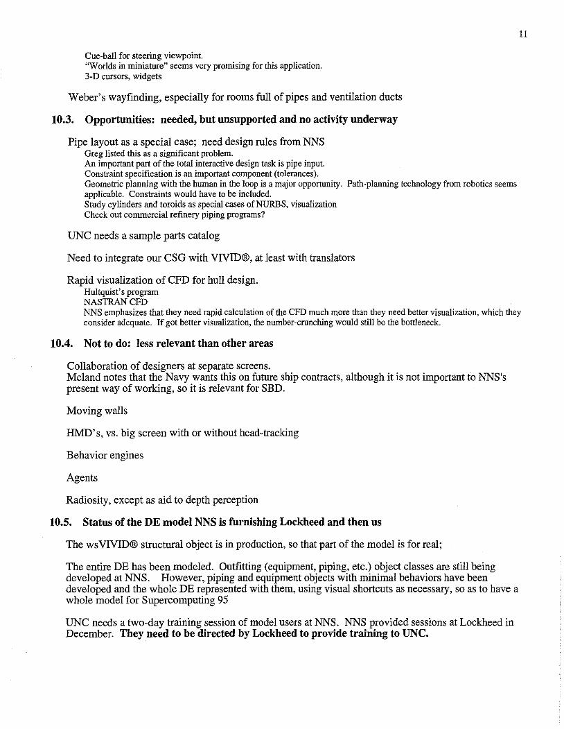
Facilities
• 222 Hectares • 3.2 kilometers of Waterfront • SDryDocks • 2 Outfitting Berths • 5 Outfitting Piers • 4.5 hectare Steel Fabrication Center • 12,000 square meter Module Outfitting Facility • Foundry Complex • Machine Shops totaling 28,000 square meters o TestLaboratories o Computer Center • Apprentice and Welding Schools
Los Angeles Class Fast Attack Submarine
Double Eagle
14
15
Training & Logistics
FF21 Fast Frigate
Design Philosophy
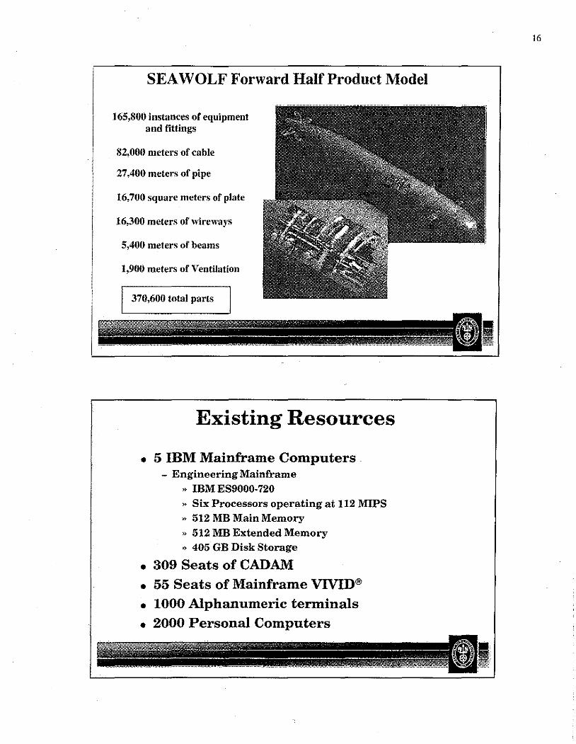
SEA WOLF Forward Half Product Model
165,800 instances of equipment and fittings
82,000 meters of cable
27,400 meters of pipe
16,700 square meters of plate
16,300 meters of "ireways
5,400 meters of beams
1,900 meters of Ventilation
370,600 total parts
Existing Resources
• 5 IBM Mainframe Computers . - Engineering Mainframe
, IBMES9000-720 , Six Processors operating at 112 MIPS , 512 MB Main Memory , 512MB Extended Memory , 405 GB Disk Storage
• 309 Seats of CAD AM • 55 Seats of Mainframe VIVID® • 1000 Alphanumeric terminals • 2000 Personal Computers
16
17
Existing Resources
• Telecommunications - Dedicated high speed fiber optics - Sophisticated, high-speed network routing devices
• 5 UNIX File Servers • 45 Novell (PC) Servers
• 5 NT Servers
Existing Resources
• Computer Aided Engineering (CAE) -Hardware
" 24 Silicon Graphic Workstations " 62 Pentium PC's
-Software " SDRC I-DEAS
• Design • Analysis
,. NASTRAN
"ABAQUS " Flowmaster ,, Triflex » Flotran
Existing Resources
• Mechanical CAD - 45 Silicon Graphic Workstations - SDRC I-DEAS
" Design , Drafting "Assembly
• wsVIVID® - 53 Silicon Graphic Workstations
• Manufacturing Systems - MPX and Pro Model for Simulation Software
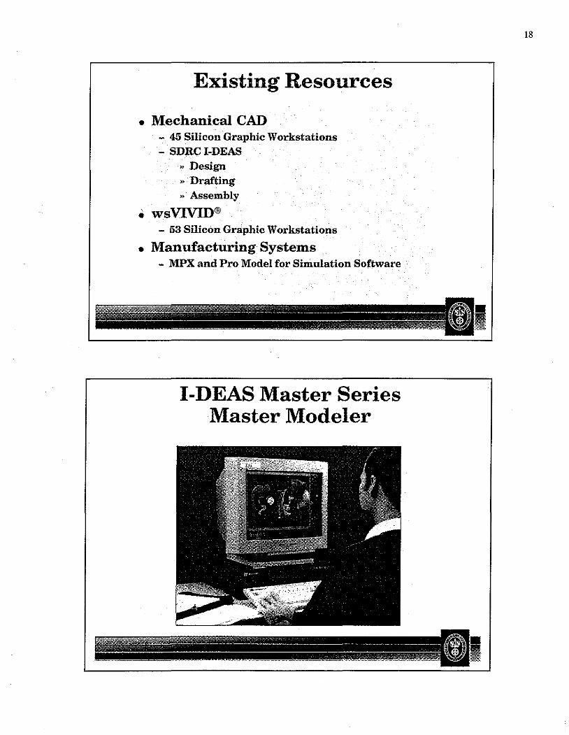
I-DEAS Master Series Master Modeler
18
19
Web Line Overview
Overview of Profile Line

Production Process Upgrade
• Large Panel Line - Automated fit-up and welding of 16x18 meter
stiffened plate panels
• Double Bottom Line - Automated fit-up and robotic welding of double
bottom units
• Curved Block Line - Semi automated fit-up and welding of curved hull
blocks
Production Process Upgrade
• Robotic Profile Cutting Line • Automated Web Line
- Robotic Welding of Flat 3xl8 meter stiffened flat plate panels
- 3 Robots on 2 gantries
• Plate Milling Machine - Edge prep plates going to automated single side
welding station
• Small Panel Line - Robotic welding of 12x14 meter flat stiffened plate
panels
20
21
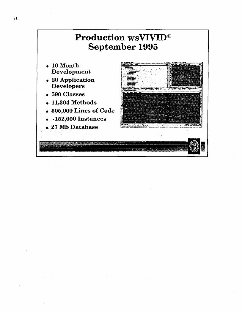
Production wsVIVID® September 1995
• lOMonth Development
• 20 Application Developers
• 590 Classes • 11,304 Methods • 305,000 Lines of Code • -152,000 Instances • 27 Mb Database