
NEWAC Overview April 2009 · from bleed valve Casing Treatment ... Project Set -up LFMT SONATS. ......
64
Overview Dr. Joerg Sieber , MTU Aero Engines
Transcript of NEWAC Overview April 2009 · from bleed valve Casing Treatment ... Project Set -up LFMT SONATS. ......
Overview
Dr. Joerg Sieber , MTU Aero Engines
April 2009Dr. J. Sieber 2This document and the information contained are property of the NEWAC consortium and shall not be copied or disclosed to any third party without prior written authorization.
Contents
� Future Requirements and EU Technology Projects
� Technical Approach
� NEWAC Program
� Subprograms• Whole Engine Integration• Intercooled Recuperated Core• Intercooled Core• Active Core• Flow Controlled Core• Innovative Combustor

Future Requirementsand
EU Technology Projects

April 2009Dr. J. Sieber 4This document and the information contained are property of the NEWAC consortium and shall not be copied or disclosed to any third party without prior written authorization.
VISION 2020 TargetsACARE (Advisory Council of Aeronautical Research in Europe)
Environment•Reduce CO2 by 50%•Reduce NOx by 80%•Reduce perceived noise by half
Safety & Security•Reduce accident rate by 80%•Zero successful hijack
Quality & Affordability•Halve time to market•Fall in travel charges
Air Transport System Efficiency•On time arrival/departure 99%within 15 minutes
• Increase movements of aircraft x3
Engine Contribution
• Reduce specific fuel consumption by 20%
• Reduce NOx by 60 to 80%
• Reduce noise by 10 dB per operation
• Reduce accident rate by x5
• Reduce operational costs
• Half time to market
Reference: year 2000 in service engine

April 2009Dr. J. Sieber 5This document and the information contained are property of the NEWAC consortium and shall not be copied or disclosed to any third party without prior written authorization.
ACARE Reference
NEWACHigh spool components, Intercooler, Recuperator
VITALLow spool components for
DDTF, GTF and CRTF
EEFAE Validation at engine level
ANTLE&CLEANComponent improvements,New components
LP component impr. New LP components
HP component impr. New HP components
SILENCER Noise reduction
technologies
Engine ValidationConcept 2
year 2000 in service engine
Engine ValidationConcept 1
April 2009Dr. J. Sieber 6This document and the information contained are property of the NEWAC consortium and shall not be copied or disclosed to any third party without prior written authorization.
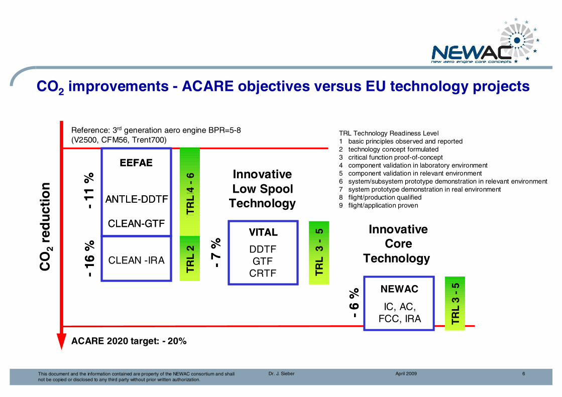
CO2 improvements - ACARE objectives versus EU technology projects
EEFAE
ANTLE-DDTF
CLEAN-GTFVITAL
TR
L 4
TR
L 2
TR
L 3
-5
NEWAC
TR
L 3
-11
%
-7
%
-6
%
-16
%
EEFAE
ANTLE-DDTF
CLEAN-GTF
Reference: 3rd generation aero engine BPR=5-8(V2500, CFM56, Trent700)
VITAL
DDTFGTF
CRTF
TR
L 4
-6
T
RL
2
TR
L 3
-5
NEWAC
IC, AC,FCC, IRA T
RL
3 -
5
InnovativeLow SpoolTechnology
InnovativeCore
Technology
-11
%
-7
%
-6
%ACARE 2020 target: - 20%
CLEAN -IRA
-16
%
CO
2re
du
ctio
n
TRL Technology Readiness Level1 basic principles observed and reported2 technology concept formulated3 critical function proof-of-concept4 component validation in laboratory environment5 component validation in relevant environment6 system/subsystem prototype demonstration in relevant environment7 system prototype demonstration in real environment8 flight/production qualified9 flight/application proven

April 2009Dr. J. Sieber 7This document and the information contained are property of the NEWAC consortium and shall not be copied or disclosed to any third party without prior written authorization.
NOx Reduction – Status / ICAO Limits / ICAO Objectives
JT-3
JT-8
JT-9
PW-4000
BR700
CFM-56
CFM-56 DAC
V-2500
CF6-50
CF6-80
GE-90(DAC-geom.)
RB-211
RR Trent
ICAO: International Civil Aviation Organisation
CAEP: Committee on Aviation Environmental Protection
CAEP/3: all engines (from 2007)
CAEP/4: new engines (from 2003)
CAEP/6: certification date aft 2008
20
40
60
80
100
120
140
10 20 30 40 50OPR
ICA
O N
OX
[g
/kN
]
ICAO 95 (CAEP/1)
ICAO 96 (CAEP/2)
CAEP/4
CAEP/3
CAEP/6
0
ICAO Medium Term Goal
ICAO Long Term Goal
Technical Approach

April 2009Dr. J. Sieber 9This document and the information contained are property of the NEWAC consortium and shall not be copied or disclosed to any third party without prior written authorization.
Thermal Efficiency for Different Engine Cycles
5 5010 20 100
The
rmal
Eff
icie
ncy
Overall Pressure Ratio
Conventional
IntercooledRecuperated
Intercooled
Active-/FlowControlled

April 2009Dr. J. Sieber 10This document and the information contained are property of the NEWAC consortium and shall not be copied or disclosed to any third party without prior written authorization.
NEWAC Core Concepts
Intercooled Recuperative Core Intercooled Core
Active Core Flow Controlled Core

April 2009Dr. J. Sieber 11This document and the information contained are property of the NEWAC consortium and shall not be copied or disclosed to any third party without prior written authorization.
NEWAC Key Technologies for New Engine Cycles
IntercoolerCross-corrugated plate heat exchanger
Ducting• Low pressure loss
ducts• Advanced IPC outlet
guide vane/diffuser
Engine Integration
RecuperatorHeat exchanger arrangement and nozzle geometry concept
Radial compressorInnovative radial compressor suitable for IRA integration
SP3 RR
SP2 MTU
SP2 TM
SP6 Avio, RR, TM
CombustorInjection systems for lean combustion
April 2009Dr. J. Sieber 12This document and the information contained are property of the NEWAC consortium and shall not be copied or disclosed to any third party without prior written authorization.
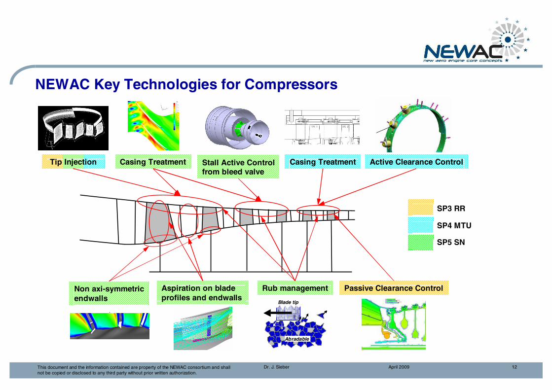
NEWAC Key Technologies for Compressors
Tip Injection Active Clearance Control
Aspiration on blade profiles and endwalls
Non axi-symmetricendwalls
Casing Treatment
SP3 RR
SP4 MTU
SP5 SN
Stall Active Controlfrom bleed valve
Casing Treatment
Rub management Passive Clearance Control
Blade tip
Abradable
Blade tip
Abradable
NEWAC Program

April 2009Dr. J. Sieber 14This document and the information contained are property of the NEWAC consortium and shall not be copied or disclosed to any third party without prior written authorization.
SP 1Whole
Engine Integration
RRUK
NEWAC Project Structure
SP 0NEWAC Coordination and Technical Management
MTU
SP 3Intercooled
Core
RRUK
Intercooler and ducting
HPC technologies
for intercooledcore operability
needs
SP 4ActiveCore
MTU
Active coolingair cooling
Smart HPCtechnologies
SP 5Flow
Controlled CoreSM
HPC flow control
technologies for highest
aerodynamicloading
SP 6Innovative Combustor
AVIO
Lean direct injection
Partial evaporat. & rapid mixing
injection
Lean premixed pre-vaporised
injection
SP 2Intercooled
RecuperativeCoreMTU
IRA core- Recuperator- Centrifugal
HPC
Future innovative core configurations
April 2009Dr. J. Sieber 15This document and the information contained are property of the NEWAC consortium and shall not be copied or disclosed to any third party without prior written authorization.
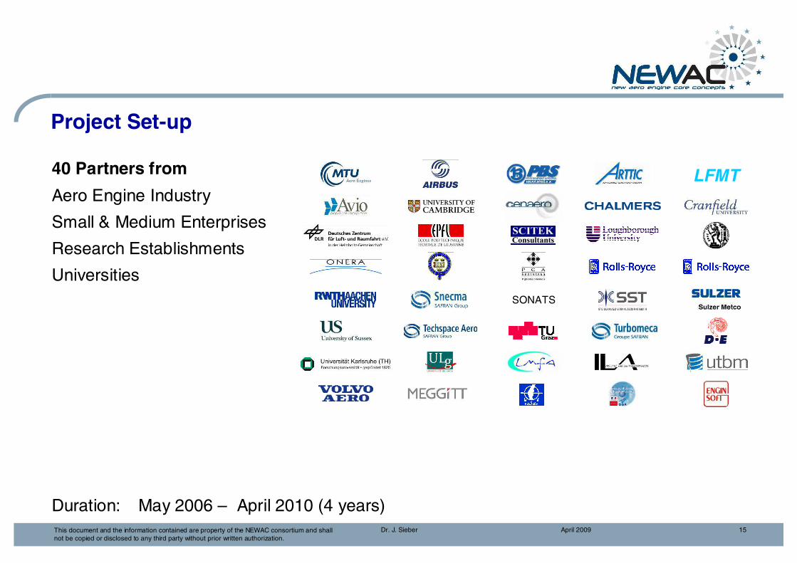
40 Partners from
Aero Engine Industry
Small & Medium Enterprises
Research Establishments
Universities
Duration: May 2006 – April 2010 (4 years)
Project Set-up
LFMT
SONATS

April 2009Dr. J. Sieber 16This document and the information contained are property of the NEWAC consortium and shall not be copied or disclosed to any third party without prior written authorization.
Target: 6 % CO2 Reduction16% NOX Reduction
Coordinator:MTU Aero Engines
40 Partners:(Engine Manufacturers, Air Framer Airbus, Equipment manufacturer, Universities, Research centres and SME's)
Project duration:May 2006 – April 2010
Total budget: 71 M€
EC contribution: 40 M€
U. Oxford
U. Sussex
RRScitek U. Loughborough
AVIO
PCA
U. Cranfield
MTU
TA
Steigerwald
U. Aachen
U. Graz
DLR
PBS
U. Belfort
U. Lyon
WSK
RRD
U. Chalmers
VAC
ARTTIC
U. Florence
Sonats
ONERA
AirbusTM
U. Athens
U. Thessaloniki
EnginSoft
U. Stuttgart
U. Karlsruhe
U EPFL
VMSulzer
U. Liege
CENAERO
SNECMACEPr
U. Cambrigde
Engine Industry & Industry
Research Establishment
University
NEWAC Consortium

April 2009Dr. J. Sieber 17This document and the information contained are property of the NEWAC consortium and shall not be copied or disclosed to any third party without prior written authorization.
NEWAC Project StructureSP1
Whole Engine Integration
RRUK
SP2Intercooled
Recuperative CoreMTU
SP3Intercooled Core
RRUK
SP4Active Core
MTU
SP5Flow Controlled
CoreSN
SP6Innovative Combustor
AVIO
WP1.3TERA
CU
WP1.1Specification, assessment & coordination
SN
WP2.2IRA Components
MTU
WP2.3Future Innovative
Core ConfigurationsVAC
WP3.5Stability
Enhancement for Intercooled Core
RRD
WP3.2Whole Engine Integration of
Intercooled ConceptVAC
WP3.3Intercooler
Aerothermal SystemsRRUK
WP3.4Improved Blading& Gaspath Design
RRUK
WP4.2Active Cooling
Air CoolingVAC
WP4.3Smart HPC
TechnologiesMTU
WP4.4Validation test
campaignMTU
WP5.2Tip flow control
& advanced aeroSN
WP5.3Aspiration concept on
blade profilesSN
WP6.2Adv. Inject. Sys. &
Fuel Spray Techno. Develop.
RRD
WP6.3Ultra low emissions
Combust. Chamber Design
TM
WP6.4Ultra low emission
Combust. Techno. Valid.
AVIO
WP1.2Concept Integration
& OptimisationMTU
WP2.1Specification, assessment &
coordinationMTU
WP3.1Specification, assessment &
coordinationRRUK
WP5.1Specification, assessment & coordination
SN
WP4.1Specification, assessment & coordination
MTU
WP6.1Specification, assessment & coordination
AVIO
WP3.6Technology Validation
Rig ManufactureRRUK
WP3.7Technology Validation
Rig TestRRD
WP5.4Blade/casing rub
management for tighttip clearance
TA
WP5.5Flow stability
control integrationSN
WP5.6Compressor rig test
validationSN

April 2009Dr. J. Sieber 18This document and the information contained are property of the NEWAC consortium and shall not be copied or disclosed to any third party without prior written authorization.
NEWAC subprojectsExploitable Outcomes
NEWAC innovative core configurations
Intercooled recuperative
core
Intercooled recuperative
core
SP2SP2
Intercooledcore
Intercooledcore
SP3SP3
Active coreActive core
SP4SP4
Flow controlled
core
Flow controlled
core
SP5SP5
Innovative combustorInnovative combustor
SP6SP6
Global enginesignificance
IRA + LPP combustor-2% CO2 -10% NOX
IRA + LPP combustor-2% CO2 -10% NOX
Optimised core configuration
Optimised core configuration
Innovative core configuration- 6 % CO2 - 16 % NOX
Innovative core configuration- 6 % CO2 - 16 % NOX
ACARE targets achievable with other
results
CO2 ����NOx exceed
target
CO2 ����NOx exceed
target
CO2 ����NOx close to
target
CO2 ����NOx close to
target
IRA +
LPP combustor- 2% CO2- 10% NOx
IRA +
LPP combustor- 2% CO2- 10% NOx
Intercooled core +
LDI combustor- 4% CO2
- 16% NOx
Intercooled core +
LDI combustor- 4% CO2
- 16% NOx
Active core+
PERM combustor- 4% CO2
- 12% NOx
Active core+
PERM combustor- 4% CO2
- 12% NOx
Flow controlledcore +
LDI combustor- 3% CO2- 12% NOx
Flow controlledcore +
LDI combustor- 3% CO2- 12% NOx
ExpetedResults

SubprogramWhole Engine Integration
April 2009Dr. J. Sieber 20This document and the information contained are property of the NEWAC consortium and shall not be copied or disclosed to any third party without prior written authorization.
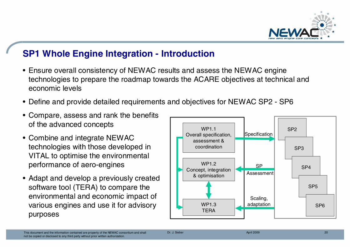
SP1 Whole Engine Integration - Introduction
• Ensure overall consistency of NEWAC results and assess the NEWAC engine technologies to prepare the roadmap towards the ACARE objectives at technical and economic levels
• Define and provide detailed requirements and objectives for NEWAC SP2 - SP6
• Compare, assess and rank the benefitsof the advanced concepts
• Combine and integrate NEWAC technologies with those developed inVITAL to optimise the environmentalperformance of aero-engines
• Adapt and develop a previously created software tool (TERA) to compare theenvironmental and economic impact of various engines and use it for advisory purposes
SP2
SP3
SP4
SP5
SP6
Scaling,adaptation
SpecificationWP1.1
Overall specification, assessment & coordination
SP Assessment
WP1.2Concept, integration
& optimisation
WP1.3TERA

April 2009Dr. J. Sieber 21This document and the information contained are property of the NEWAC consortium and shall not be copied or disclosed to any third party without prior written authorization.
SP1 Whole Engine Integration - Technical Approach
Long Range
4 Engine Configurations
Short Range1450
1500
155
0
16
00
16
50
17
00
17
50
18
00
18
50
19
00
90
0
95
0
10
00
10
50
11
00
11
5012
0012
5013
00
30 35
40
45 50 55 60
90
0
95
0
10
00
10
50
11
00
11
50
12
00
12
50
1600
1650 1700 1750
1800
190
0
95
010
0 010
5 0
11
00
11
50
12
00
12
50
1600
1650 1700 1750
1800
190
BPR = 10
BPR = 12
BPR = 14
2 Aircraft Configurations
April 2009Dr. J. Sieber 22This document and the information contained are property of the NEWAC consortium and shall not be copied or disclosed to any third party without prior written authorization.
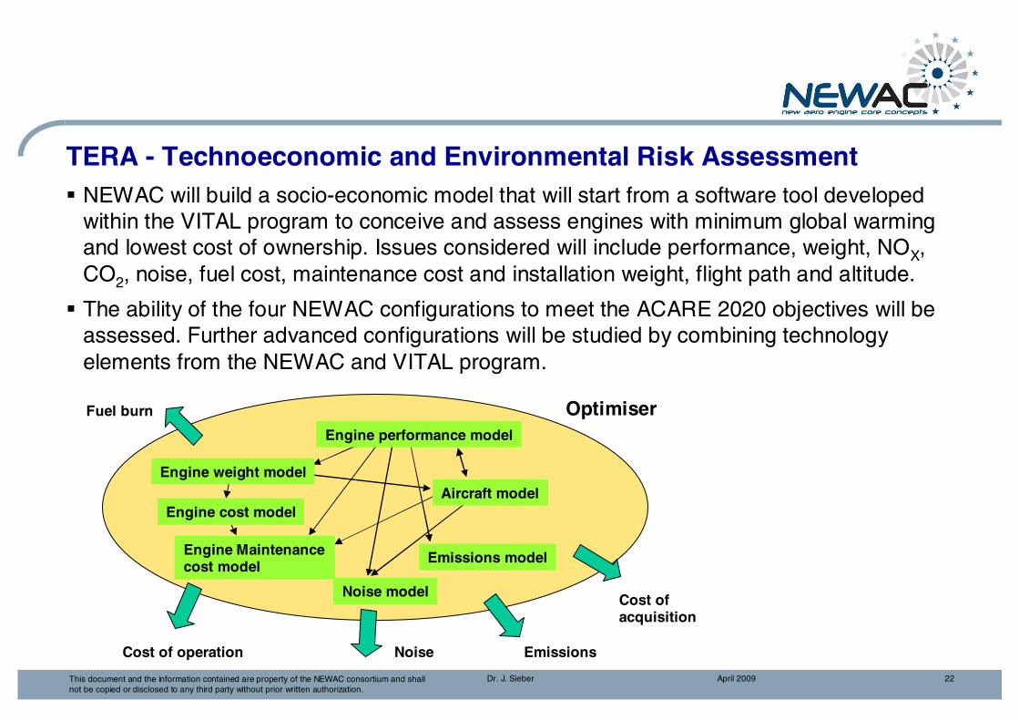
TERA - Technoeconomic and Environmental Risk Assessment� NEWAC will build a socio-economic model that will start from a software tool developed
within the VITAL program to conceive and assess engines with minimum global warming and lowest cost of ownership. Issues considered will include performance, weight, NOX, CO2, noise, fuel cost, maintenance cost and installation weight, flight path and altitude.
� The ability of the four NEWAC configurations to meet the ACARE 2020 objectives will be assessed. Further advanced configurations will be studied by combining technology elements from the NEWAC and VITAL program.
Optimiser
EmissionsNoise
Cost of acquisition
Fuel burn
Cost of operation
Engine performance model
Aircraft model
Emissions model
Noise model
Engine weight model
Engine cost model
Engine Maintenance cost model
SubprogramIntercooled Recuperative
Aero Engine
April 2009Dr. J. Sieber 24This document and the information contained are property of the NEWAC consortium and shall not be copied or disclosed to any third party without prior written authorization.
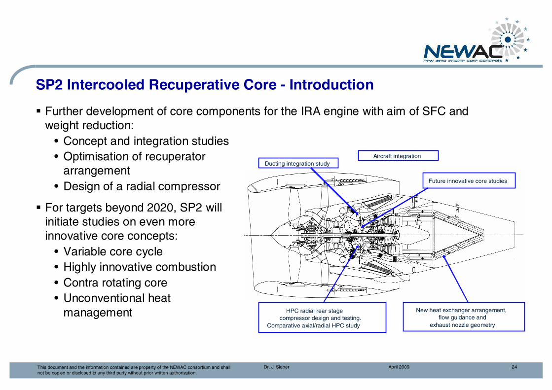
SP2 Intercooled Recuperative Core - Introduction
� Further development of core components for the IRA engine with aim of SFC and weight reduction:
• Concept and integration studies• Optimisation of recuperator
arrangement• Design of a radial compressor
� For targets beyond 2020, SP2 willinitiate studies on even more innovative core concepts:
• Variable core cycle• Highly innovative combustion • Contra rotating core • Unconventional heat
management
Ducting integration study
New heat exchanger arrangement, flow guidance and
exhaust nozzle geometry
HPC radial rear stagecompressor design and testing.
Comparative axial/radial HPC study
Future innovative core studies
Aircraft integration

April 2009Dr. J. Sieber 25This document and the information contained are property of the NEWAC consortium and shall not be copied or disclosed to any third party without prior written authorization.
IPC
Fan
HPTHPC LPT
IPT
RecuperatorIntercooler
Recuperator
Pylon
Nacelle
Intercooler
Tubing
Intercooled Recuperative Aero Engine
HPCFan & IPC
Core Nozzle
LPT
CombustorTem
per
atu
re [k
]
2.8
3
3.3
5
8
Conventional Cycle
Recuperator
Intercooler
Entropy [kJ/kgK]
0
200
400
600
800
1000
-.2 0 .2 .4 .6 .8 1 1.2 1.4
1200
1400
1600
1800
HPT

April 2009Dr. J. Sieber 26This document and the information contained are property of the NEWAC consortium and shall not be copied or disclosed to any third party without prior written authorization.
SP2 Intercooled Recuperative Core - Objectives
High level objectives
� Further develop IRA core components resulting in• 2% SFC reduction in addition to 16% SFC reduction achieved from CLEAN IRA• 1% propulsion system weight reduction
� Initiate system level studies on even more innovative core concepts with respect to further challenging targets compared to ACARE 2020 objectives
Technical objectives
� to optimise and improve IRA engine cycle and configuration
� to study integration issues and structural aspects
� to improve internal losses compared to EEFAE CLEAN results• to improve heat transfer by changing HEX configuration and HEX arrangement• to improve radial HPC efficiency by 0.8% at 10% lower radial HPC weight

April 2009Dr. J. Sieber 27This document and the information contained are property of the NEWAC consortium and shall not be copied or disclosed to any third party without prior written authorization.
SP2 Intercooled Recuperative Core - Technical Approach
Recuperator
� Improved heat exchanger and nozzle arrangement
� Low loss heat exchanger integration
� Structural and overall IRA integration aspects
Radial HP Compressor
� Radial compressor efficiency improvement and high hub-tip-ratio
� Optimisation of radial compressor/ducting interface
� Radial/axial compressor comparison
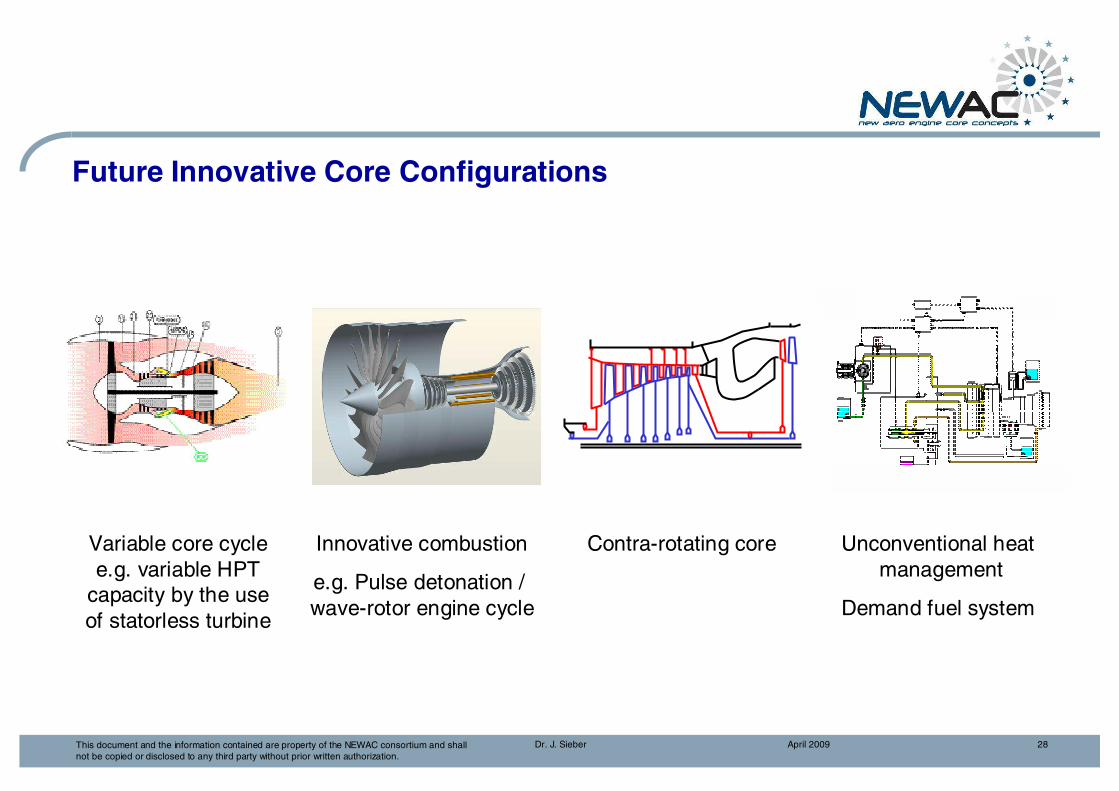
Future innovative core configuration
� Variable core cycle� Innovative combustion
� Contra-rotating core� Unconventional heat management
April 2009Dr. J. Sieber 28This document and the information contained are property of the NEWAC consortium and shall not be copied or disclosed to any third party without prior written authorization.
Unconventional heat management
Demand fuel system
Contra-rotating coreInnovative combustion
e.g. Pulse detonation / wave-rotor engine cycle
Variable core cycle e.g. variable HPT
capacity by the use of statorless turbine
Future Innovative Core Configurations

SubprogramIntercooled Core

April 2009Dr. J. Sieber 30This document and the information contained are property of the NEWAC consortium and shall not be copied or disclosed to any third party without prior written authorization.
SP3 Intercooled Core - Introduction
One way to achieve the improvements required by the ACARE 2020 objectives is to utilise a high overall pressure ratio, intercooled cycle. This can be applied in two ways:
� For a given turbine entry temperature, overall pressure ratio and combustor technology, NOX will be reduced due to the lower combustor entry and flame temperatures.
� For a given NOX level and material technology, the cycle overall pressure ratio can be increased leading to CO2 reduction.

April 2009Dr. J. Sieber 31This document and the information contained are property of the NEWAC consortium and shall not be copied or disclosed to any third party without prior written authorization.
SP3 Intercooled Core - Objectives
� To validate duct and heat exchanger technologies that allow the utilisation of an intercooled configuration to realize a 2.0% SFC improvement and a 15% NOXreduction for an engine with an increased overall pressure ratio.
• The SFC and NOx benefits can be optimized with respect to engine size.
• The intercooled cycle will also enable a 0,5% SFC benefit through a reduction in turbine cooling air mass flow (reduced cooling air temperature).
� To improve HPC efficiency and hence improve SFC by 1.5%, relative to EEFAE ANTLE design, through the use of advanced design and novel systems.
• These benefits will be applicable to both conventional and intercooled cycle engines.
� The total benefit that could be achieved just through the intercooled cycle and compressor technologies is 4% SFC and 16% NOX reduction for an engine with increased OPR.

April 2009Dr. J. Sieber 32This document and the information contained are property of the NEWAC consortium and shall not be copied or disclosed to any third party without prior written authorization.
SP3 Intercooled Core - Technical Approach
Intercooler and related ducting
� Design and test advanced cross-corrugated plate heat exchanger
� Design and validation of low pressure loss ducts
� Advanced OGV/diffuser
Improved HPC (higher overall pressure ratio)
� Stability enhancement for intercooled core operability needs
� Improved blading and secondary flow path
� Improved tip clearance design

April 2009Dr. J. Sieber 33This document and the information contained are property of the NEWAC consortium and shall not be copied or disclosed to any third party without prior written authorization.
SP3 Intercooled Core
Cross-Corrugated Heat Exchanger Matrix
Ducting System
Preliminary Intercooled Engine Layout
Cold side
Hot side

April 2009Dr. J. Sieber 34This document and the information contained are property of the NEWAC consortium and shall not be copied or disclosed to any third party without prior written authorization.
SP3 Stability Enhancement for Intercooled Core
Rotor 1 with tip blowing for significant surge margin increase

SubprogramActive Core

April 2009Dr. J. Sieber 36This document and the information contained are property of the NEWAC consortium and shall not be copied or disclosed to any third party without prior written authorization.
SP4 Active Core - Introduction
� Active systems open up a new area of technological opportunities, they offer• the possibility to adapt the core engine to each operating condition of the mission
and, therefore, the potential to optimise component and cycle behaviour, • additional degrees of freedom in the design, as the core does not need not to be
designed on a worst case basis,• compensation of efficiency and safety penalties due to deterioration to a certain
degree by adjusting the core to the actual conditions.
� In SP4 the most promising active systems for core engine applications will be investigated and compared with passive alternatives:
• active cooling air cooling system for reduced cooling air consumption, • active or semi-active clearance control system for HPC rear stages, • active or passive surge control system for HPC front stages.
� The candidates with the highest overall potential will be developed and validated.

April 2009Dr. J. Sieber 37This document and the information contained are property of the NEWAC consortium and shall not be copied or disclosed to any third party without prior written authorization.
SP4 Active Core - Objectives
The overall target of SP4 is to develop and validate a system of active or semi-active core engine technologies which reduce the SFC by 4% due to increased core component efficiencies, core cycle improvements and related overall engine effects.
• Highly advanced active cooling air cooling system, which aims at a reduction of the high pressure turbine cooling air consumption and an increase of the HPT efficiency.� SFC reduction: 1,5%
• Active or semi-active clearance control system for compressor rear stages and an active or passive surge control system for the compressor front stages, with the objective of higher efficiency and improved aerodynamic stability (“smart compressor”)� SFC reduction: 1,1%
• Improvement of the engine cycle due to higher overall pressure ratio and bypass ratio� SFC reduction: 1,4%

April 2009Dr. J. Sieber 38This document and the information contained are property of the NEWAC consortium and shall not be copied or disclosed to any third party without prior written authorization.
SP4 Active Core Configuration - Technical Approach
Active clearance control system (rear stages)
� Improved tip clearance with active clearance control system (thermal or mechanical)
� Comparison with alternative technologies for tip clearance improvement
Active cooling air cooling
� General concept� Air cooler and control system
Active surge control (front stages)
� Development of an active surge control with air injection
� Comparison to the passive alternative multi stage casing treatment
� Combustor case cooling air flow path� HPC rear cone cooling

April 2009Dr. J. Sieber 39This document and the information contained are property of the NEWAC consortium and shall not be copied or disclosed to any third party without prior written authorization.
Active Cooling Air Cooling - Introduction
� In modern gas turbines up to 30% of the compressor air is used for cooling purposes significantly increasing the fuel consumption.
� In known studies cooled cooling air is used for HPT blades only and the amount and temperature of the cooled air is fixed.
� In SP4 a new, highly advanced active cooling air system will be investigated. Not only the rotor blades, but also the stator vanes, the rotor disk and the liner are supplied with cooled cooling air. In addition the cooling air mass flow rate and temperature are actively controlled depending on the mission point. By this, it is possible to reduce the necessary amount of cooling air to a minimum.

April 2009Dr. J. Sieber 40This document and the information contained are property of the NEWAC consortium and shall not be copied or disclosed to any third party without prior written authorization.
Active Cooling Air Cooling - Objectives
� To develop a concept of a highly advanced cooling air cooling system, which aims at
• a reduction of the high pressure turbine cooling air consumption by 35 %,
• an increase of the HPT efficiency by 1 % and
• a significant increase of the specific HPT work
• resulting in a total SFC reduction of 1.5 % (not including the OPR effect and the BPR effect).
� To validate the necessary key components
• air cooler and control system,
• combustor case with optimised cooled cooling air flow path,
• manufacturing technologies for a thinner compressor rear cone, which is cooled by cooled cooling air.

April 2009Dr. J. Sieber 41This document and the information contained are property of the NEWAC consortium and shall not be copied or disclosed to any third party without prior written authorization.
Active Cooling Air Cooling
1 Combustor case2 Heat exchanger3 Bypass air4 Valve5 Compressor rear cone cooling6 HPT airfoil cooling

April 2009Dr. J. Sieber 42This document and the information contained are property of the NEWAC consortium and shall not be copied or disclosed to any third party without prior written authorization.
Smart HPC Technologies - Introduction
� Active systems offer the possibility to adapt the core engine to each operating point of the mission and therefore have a significant potential to optimise component behaviour. Furthermore, active systems open up additional degrees of freedom in the design and the possibility of compensating efficiency and safety penalties due to deterioration.
� The two most promising areas of application of active systems in the core are active clearance control and active surge control systems for the HP compressor. They will be investigated and compared with passive alternatives.
� The candidates with the highest potential will be developed and validated in rig tests.

April 2009Dr. J. Sieber 43This document and the information contained are property of the NEWAC consortium and shall not be copied or disclosed to any third party without prior written authorization.
� Efficiency improvement by active or semi-active clearance control
� Surge Margin1. Increased full speed surge
margin by active clearance control or casing treatment for rear stages
2. Increased part speed surge margin by active surge control or casing treatment for front stages
3. Lifting of working line
�Reduced compressor size and higher compressor efficiency
3
1
2
Mass Flow
Pre
ssur
e R
atio
Smart HPC Technologies - Strategy

April 2009Dr. J. Sieber 44This document and the information contained are property of the NEWAC consortium and shall not be copied or disclosed to any third party without prior written authorization.
Smart HPC Technologies - Objectives
� To develop active or semi-active systems for HP compressors
• active or semi-active clearance control system for compressor rear stages providing significantly better efficiency and full speed surge margin and
• active or passive surge control system for compressor front stages enhancing the operability of the engine at part speed conditions.
� Together theses technologies will provide
• a 1.5 % higher HPC efficiency and
• a lower HPC size and weight due to lifting of the HPC operating line by 15 %,
• the resulting SFC reduction is at a value of 1.1 % (not including the OPR and BPR effects).
� To investigate the key issues weight, system complexity and robustness against failure.
� To validate the technologies in a series of rig tests.

April 2009Dr. J. Sieber 45This document and the information contained are property of the NEWAC consortium and shall not be copied or disclosed to any third party without prior written authorization.
Smart HPC Technologies - Air Injection & Casing Treatment
Air injection
Casing treatment
Blade
Mass FlowP
ress
ure
Rat
io
� Increased part speed surge margin(applied to front stages)
Variable nozzles
Injection ducts
Air supply
Blade

April 2009Dr. J. Sieber 46This document and the information contained are property of the NEWAC consortium and shall not be copied or disclosed to any third party without prior written authorization.
Smart HPC Technologies - Active Clearance Control
Active Clearance Control (ACC)
Mass FlowP
ress
ure
Rat
ioTime
Casing
Rotor
Clearance
Rad
ial M
otio
n
Speed
� Increased efficiency
� Increased full speed surge margin(applied to rear stages)

April 2009Dr. J. Sieber 47This document and the information contained are property of the NEWAC consortium and shall not be copied or disclosed to any third party without prior written authorization.
Smart HPC Technologies - Active Clearance Control
Example for mechanical clearance control• Long lever driven by actuators rotates inner ring circumferentially relative to outer carrier ring• Oblique struts cause radial punch loads between rings. • Inner ring shows radial shrink relative to stiffness ratio between outer carrier ring and inner flowpath ring
Outer Case
Stiff Carrier Ring
Flexible Inner Ring
Lever
Rotation Point
Struts
Connection to Actuator

SubprogramFlow Controlled Core

April 2009Dr. J. Sieber 49This document and the information contained are property of the NEWAC consortium and shall not be copied or disclosed to any third party without prior written authorization.
SP5 Flow Controlled Core - Introduction
• To achieve compressor efficiency increase, additional surge margin and reduced in service deterioration, flow control technologies offer new opportunities. These technologies are:
• Tip flow control technologies including aspiration• New advanced 3D aerodynamics• Air aspiration applied on stator vane/hubs or blade• Blade/casing rub management for tight tip clearance • Flow stability control optimised versus engine integration
• The flow control technologies will be investigated by analysis, elementary tests and validated in a compressor rig test.

April 2009Dr. J. Sieber 50This document and the information contained are property of the NEWAC consortium and shall not be copied or disclosed to any third party without prior written authorization.
SP5 Flow Controlled Core - Objectives
Blade/casing rub management
• + 0.5pt efficiency• + 2% SM• Lower rub clearance opening
Blade aspiration concept• + 0.5pt efficiency• + 5% SM<=> equivalent blade loading
Tip Flow Control and Advanced Aero• + 1.5pt efficiency w/o SM penalty• Lower efficiency deterioration• Additional +8% SM from Stall active Ctrl
Linke d to en ginea ir sys tem
Wal
l as
pira
tion
Tip injection
Linke d to en ginea ir sys tem
Wal
l as
pira
tion
Tip injection
Linke d to en ginea ir sys tem
Wal
l as
pira
tion
Tip injection
Linke d to en ginea ir sys tem
Wal
l as
pira
tion
Tip injection
SP5 NEWAC objectives for HPC: • +2.5% efficiency • +15% stall margin• -1/3 deterioration in service

April 2009Dr. J. Sieber 51This document and the information contained are property of the NEWAC consortium and shall not be copied or disclosed to any third party without prior written authorization.
SP5 Flow Controlled Core - Technical Approach
Aspiration concept on blade profiles
� Evaluation and optimisation of aspiration technology on stator vane/hubs or blade
� Identification of potential benefits
Tip flow control
� Advanced casing treatment� Tip rotor injection with/without aspiration
Stall active control system integration
� Studies with thermal, mechanical, technological, hydraulic constraints
� Overview of issued encountered with implementation of each system
Rub management
� Modelling the abradable and its wearing� Development of improved abradable� Validation via rub tests…

April 2009Dr. J. Sieber 52This document and the information contained are property of the NEWAC consortium and shall not be copied or disclosed to any third party without prior written authorization.
Tip Flow Control and Advanced AeroConcepts for efficiency/operability enhancement• 3D airfoil design optimized and adapted to the casing environment• Non axi-symmetric end wall• Advanced casing treatment• Casing aspiration• Tip injection
Flow controlled compressorwith tip injection and casing aspiration

April 2009Dr. J. Sieber 53This document and the information contained are property of the NEWAC consortium and shall not be copied or disclosed to any third party without prior written authorization.
Reference With aspiration
Aspiration concept on blade profiles
� To delay separation at high incidence / loading
� To reduce shock/boundary layer interaction
�Improved blade stability / efficiency / loading

April 2009Dr. J. Sieber 54This document and the information contained are property of the NEWAC consortium and shall not be copied or disclosed to any third party without prior written authorization.
Blade/casing rub management for tight tip clearances
� Engine performances calls for tight tip clearances for the compressor at cruise (efficiency), in transient (operability) and in-service whole engine life (performance).
� Small tip clearances lead to contact between rotor and stator parts which inescapably leads to wider clearances than targeted. Development of new material, robust technologies and new design practices provides opportunities for a better blade / casing rub control.
Abradability phenomena
� Approach
• Development of a specific methodology, taking into account the entire structure characteristics, modelling the abradable and its wearing, machining loads and thermal effects, with sophisticated contact modelling.
• Development of an improved abradable, making blisksrub-proof.
• Tests with blades and abradable in order to validate the methodology, the blade design guidelines and the new abradable characteristics

April 2009Dr. J. Sieber 55This document and the information contained are property of the NEWAC consortium and shall not be copied or disclosed to any third party without prior written authorization.
Stall Active Control Integration� CLEAN EEFAE demonstrated a successful implementation of actuators & surge
avoidance (fast opening / closing valves, sensors and real time detection system)
� Implementation of the Stall Active Control on real engines requires thorough integration
• Integration studies for CLEAN-like actuators (fast opening valves) and alternative stall control systems on thermal, mechanical, technological, hydraulic aspects
• Performance assessment on benefits and penalties to be carried out

SubprogramInnovative Combustor

April 2009Dr. J. Sieber 57This document and the information contained are property of the NEWAC consortium and shall not be copied or disclosed to any third party without prior written authorization.
SP6 Innovative Combustor - Introduction
� Significant NOx reduction promising approaches are based on lean combustion technology
� EEFAE ANTLE/CLEAN proved NOx reduction encouraging progress vs. ACARE 2020 objectives
� Further improvements, mainly on fuel injection technology, are required to enable NOx target
� Major challenge is to bring identified NOx reduction technologies to a TRL 5 to 6
� Lean combustion is integrated into fuel staged combustion concepts for combustion operability
� Validation of 3 lean combustion technologies (LP(P), PERM and LDI) for different applications up to full annular high pressure test

April 2009Dr. J. Sieber 58This document and the information contained are property of the NEWAC consortium and shall not be copied or disclosed to any third party without prior written authorization.
lean 1 richEquivalence ratio
NO
X-
form
atio
n
leanburn
conven-tional
Conventional Combustor
Recirculation flow field forstabilizing of the reaction zone
NOx Reduction by Lean Combustion
� Lean combustion operates with an excess of air to significantly lower flame temperatures and consequently reduce NOx formation. Up to 70% of total combustor air flow has to be premixed with the fuel before entering the reaction zone.
� To overcome the narrow operating range of lean combustion fuel staging is required:• Staged combustor with two separated zones (additional combustion zone for good
stability at low power) either axially or radially staged • Internally staged injectors creating a pilot and main combustion zone downstream of
the injector installed in a single annular combustor
Staged combustor Single annular combustor
Lean Combustion

April 2009Dr. J. Sieber 59This document and the information contained are property of the NEWAC consortium and shall not be copied or disclosed to any third party without prior written authorization.
NOx Reduction by Lean Combustion
In NEWAC internally staged injectors will be investigated because of low emissions at acceptable penalties on weight and cost.
� LPP (Lean Premixed Prevaporized Injection)• fuel is mixed with air by a premixing tube before
reaching the combustion region • application to reverse flow combustor for IRA
engine or small gas turbines• risk of auto-ignition or flashback for higher OPR
� PERM (Partial Evaporation & Rapid Mixing)• fuel is partially evaporated and rapidly mixed
using swirler technology
� LDI (Lean Direct Injection)• fuel is injected directly into the flame zone• a concentric internally staged fuel injection
system with pilot (stability) and main stage (low NOx) is used

April 2009Dr. J. Sieber 60This document and the information contained are property of the NEWAC consortium and shall not be copied or disclosed to any third party without prior written authorization.
� Develop and validate lean fuel injection technology up to TRL 5-6, demonstrating 60% to 70% reduction of NOx emissions in the LTO cycle versus CAEP/2 limit
� Enable combustor full operability
SP6 Innovative Combustor - Objectives
CAEP/2
Active core withPERM combustor
Intercooled core with LDI combustor
EEFAE – ANTLE - CLEAN
0
20
40
60
80
100
120
10 20 30 40 50 60 70Overall Pressure Ratio (OPR)
ICA
O N
Ox
[g/k
N]
CAEP/62008
CAEP/4 2004
Trent 700
CFM 56
Reference
EEFAE – ANTLE - CLEAN
ICAO Medium Term Goal
IRA with LPP combustor
ICAO Long Term Goal
NEWAC- 60% to 70% rel. to CAEP/2
- 16% rel. to EEFAE

April 2009Dr. J. Sieber 61This document and the information contained are property of the NEWAC consortium and shall not be copied or disclosed to any third party without prior written authorization.
SP6 Innovative Combustor Technologies - Applications
4 core concepts3 injection systems
SP2 (IRA)
SP3 (IC)
SP4 (AC)
SP5 (FCC)
20
30
40
50
LP(P
)
PE
RM
LDI
En
gin
e O
PR
PERM
LP(P)
LDI

April 2009Dr. J. Sieber 62This document and the information contained are property of the NEWAC consortium and shall not be copied or disclosed to any third party without prior written authorization.
SP6 Innovative Combustor - Approach
Development towards a Ultra Low NOx lean burntechnology single annular combustor (SAC)
� Development of 3 different lean fuel injection systems (LDI, PERM and LP(P)) through CFD and detailed experimental investigations
� Design/adaptation of combustor module demonstrators, integrating advanced validated injection systems, innovative cooling technology, fuel staging concepts, thermal management of fuel injectors, control of thermo-acoustic and combustion instabilities
� Validation of lean combustor technology (TRL 5-6) on full annular combustor demonstrators to assess performance at sub-atmospheric, atmospheric up to high pressure

April 2009Dr. J. Sieber 63This document and the information contained are property of the NEWAC consortium and shall not be copied or disclosed to any third party without prior written authorization.
Advanced Injection System - Approach
Combustion Tests(LDI DLR/RRD, PERM UNIKA, LPP TM/ONERA)
Optical Rigs (TRL 3-4)(LDI DLR, PERM UNIKA, LDI TUG/ONERA)
HP Single Sector (TRL 4)(LDI DLR, PERM ONERA, LPP ONERA)
CFD Prelim Design(LDI RRD, PERM UNIKA/AVIO, LPP TM)
Optical Diagnostics(LDI DLR, PERM UNIKA, LPP TM)