NEW YK500 TW - ROBSYTECHrobsytech.fr/images/Doc PDF YAMAHA/YK350TW_YK500TW_E_0121_1st.pdfYK500 TW...
8
201501-AE IM Operations 882 Soude, Naka-ku, Hamamatsu, Shizuoka 435-0054, Japan Tel 81-53-460-6103 Fax 81-53-460-6811 http://global.yamaha-motor.com/business/robot/ URL E-mail [email protected] Specifications and appearance are subject to change without prior notice.
Transcript of NEW YK500 TW - ROBSYTECHrobsytech.fr/images/Doc PDF YAMAHA/YK350TW_YK500TW_E_0121_1st.pdfYK500 TW...

201501-AE
IM Operations882 Soude, Naka-ku, Hamamatsu, Shizuoka 435-0054, JapanTel 81-53-460-6103 Fax 81-53-460-6811
http://global.yamaha-motor.com/business/robot/URL E-mail [email protected]
New product information
YK500TWYK350TWNEW
YK350TWYK500TW
NEW
Specifications and appearance are subject to change without prior notice.
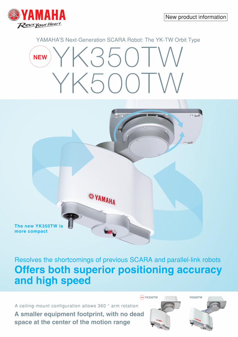
YAMAHA'S Next-Generation SCARA Robot: The YK-TW Orbit Type
The new YK350TW is more compact
Resolves the shortcomings of previous SCARA and parallel-link robots
Offers both superior positioning accuracy and high speed
A ceiling-mount configuration allows 360 ° arm rotation
A smaller equipment footprint, with no dead space at the center of the motion range
201501-AE
IM Operations882 Soude, Naka-ku, Hamamatsu, Shizuoka 435-0054, JapanTel 81-53-460-6103 Fax 81-53-460-6811
http://global.yamaha-motor.com/business/robot/URL E-mail [email protected]
New product information
YK500TWYK350TWNEW
YK350TWYK500TW
NEW
Specifications and appearance are subject to change without prior notice.
YAMAHA'S Next-Generation SCARA Robot: The YK-TW Orbit Type
The new YK350TW is more compact
Resolves the shortcomings of previous SCARA and parallel-link robots
Offers both superior positioning accuracy and high speed
A ceiling-mount configuration allows 360 ° arm rotation
A smaller equipment footprint, with no dead space at the center of the motion range
Ordering method
Note 1. This is the value at a constant ambient temperature.Note 2. Tool flange specifications (optional) apply to the YK350TW (4 kg) and the
YK500TW (3 kg).Note 3. When moving a 1 kg load back and forth 300 mm horizontally and 25 mm
vertically (rough positioning arch motion).Note 4. Limits must be placed on parameters such as acceleration according to the
moment of inertia being used.
Specifications
YK500TWYK350TW
250 mm
250 mm
+/- 0.015 mm
6.8 m/sec
4 kg0.29 sec
ф 4 × 2
27 kg
175 mm
175 mm
+/- 0.01 mm
5.6 m/sec
5 kg0.32 sec (RCX340) / 0.38 sec (RCX240)
ф 6 × 2
26 kg
+/- 225 °
+/- 225 °130 mm+/- 720 °
750 W / 400 W / 200 W / 105 WHarmonic drive / Harmonic drive / Ball screw / Belt speed reduction
Timing belt / Direct-coupled / Timing belt / Timing beltDirect-coupled / Direct-coupled / Direct-coupled / Timing belt
+/- 0.01 mm+/- 0.01 °
1.5 m/sec3000 °/sec
0.005 kgm2
0.05 kgm2
0.15 sq × 8 wires
1.Soft limit 2.Mechanical stopper (X,Y,Z axis)Standard: 3.5 m Option: 5 m,10 m
X-axis Arm length Rotation angleY-axis Arm length Rotation angleZ-axis StrokeR-axis Rotation angleX-axis / Y-axis / Z-axis / R-axis Speed reducer
Motor to speed reducer Speed reducer to outputXY axesZ-axisR-axisXY axes synthesisZ-axisR-axis
Rated Maximum
X-axis / Y-axis / Z-axis / R-axis
Transmission method
Axis specifications
AC servo motor output
Deceleration mechanism
Repeatability Note 1
Maximum speed
Maximum payload Note 2 Standard cycle time Note 3
R-axis tolerable moment ofinertia Note 4
User wiring
User tubing (Outer diameter)Travel limit
Robot cable length Weight
This next-generation YK-TW Series SCARA robot effectively resolves the shortcomings of previous SCARA and parallel-link robots
392 mm
844 mm
YK500TW YD11
Orbit type SCARA robot
A
C
B
Standard type SCARA robot
A
C
B
A
C
B
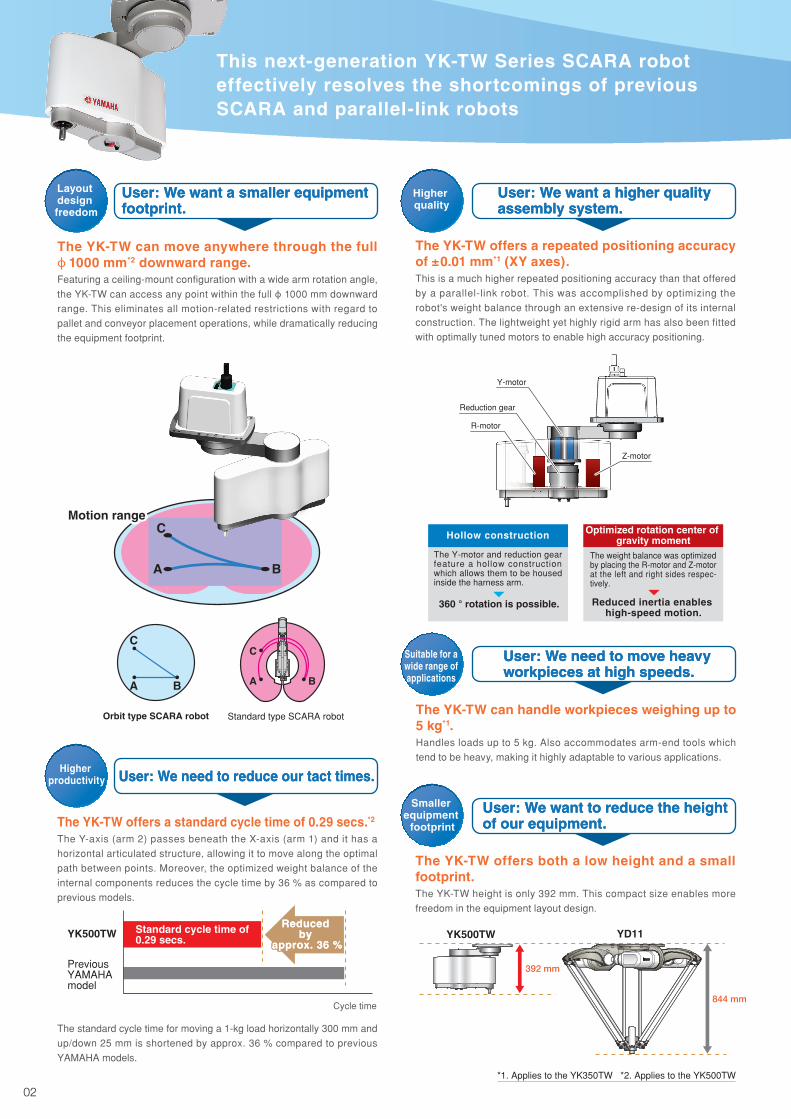
Motion range
The YK-TW offers a standard cycle time of 0.29 secs.*2
The Y-axis (arm 2) passes beneath the X-axis (arm 1) and it has a
horizontal articulated structure, allowing it to move along the optimal
path between points. Moreover, the optimized weight balance of the
internal components reduces the cycle time by 36 % as compared to
previous models.
The standard cycle time for moving a 1-kg load horizontally 300 mm and
up/down 25 mm is shortened by approx. 36 % compared to previous
YAMAHA models.
Previous YAMAHA model
Cycle time
YK500TWReduced
by approx. 36 %
Reduced by
approx. 36 %Standard cycle time of 0.29 secs.
Approx. 74 % lighter
YD11
YK500TW Weighs only 27 kg
75 kg
An optional dedicated installation frame is available for the YK-TW.
For details, contact a YAMAHA sales representative.
* Applies only to the YK350TW.
When the payload exceeds 4kg, it is predicted that the R-axis moment of inertia may exceed the rated value. So, make proper parameter setting.
The YK-TW can move anywhere through the full ф 1000 mm*2 downward range.Featuring a ceiling-mount configuration with a wide arm rotation angle,
the YK-TW can access any point within the full ф 1000 mm downward range. This eliminates all motion-related restrictions with regard to
pallet and conveyor placement operations, while dramatically reducing
the equipment footprint.
User: We want a smaller equipment footprint.User: We want a smaller equipment footprint.
Layout design freedom
User: We need to reduce our tact times.User: We need to reduce our tact times.Higher
productivity
The YK-TW offers both a low height and a small footprint.The YK-TW height is only 392 mm. This compact size enables more
freedom in the equipment layout design.
User: We want to reduce the height of our equipment.User: We want to reduce the height of our equipment.
Smaller equipment
footprint
The YK-TW has a total height of only 392 mm, and weighs only 27 kg*2.Due to its low inertia, a sturdy frame is not required.
Environment resistant
Z-motor
R-motor
Y-motor
Reduction gear
The weight balance was optimized by placing the R-motor and Z-motor at the left and right sides respec-tively.
Optimized rotation center of gravity moment
Reduced inertia enables high-speed motion.
Hollow construction
360 ° rotation is possible.
The Y-motor and reduction gear feature a hollow construction which allows them to be housed inside the harness arm.
The YK-TW offers a repeated positioning accuracy of ±0.01 mm*1 (XY axes).This is a much higher repeated positioning accuracy than that offered
by a parallel-link robot. This was accomplished by optimizing the
robot's weight balance through an extensive re-design of its internal
construction. The lightweight yet highly rigid arm has also been fitted
with optimally tuned motors to enable high accuracy positioning.
User: We want a higher quality assembly system.User: We want a higher quality assembly system.
Higher quality
The YK-TW can handle workpieces weighing up to 5 kg*1.Handles loads up to 5 kg. Also accommodates arm-end tools which
tend to be heavy, making it highly adaptable to various applications.
User: We need to move heavy workpieces at high speeds.User: We need to move heavy workpieces at high speeds.
Note. RCX340 controller will be supported from March, 2015 or later.
YK350TWYK500TW 130
Model Z axis stroke Tool flange Hollow shaft Cable130: 130mm No entry: None No entry: None 3L: 3.5m
F: With tool flange
S: With hollow shaft
5L: 5m10L: 10m
RCX340-4Note
Controller /Number of controllable axes
Safety standard
Option A(OP.A)
Option B(OP.B)
Option C(OP.C)
Option D(OP.D)
Option E(OP.E)
Absolute battery
RCX240 R3 BBController CE Marking Regeneratizve
unitExpansion
I/ONetwork
option iVY System Gripper Battery
RCX240 / RCX340 : Specify various controller setting items. P.6,7
Weight (kg)
Offset (mm)
00 1 2 3 4
204060
10080
*1. Applies to the YK350TW *2. Applies to the YK500TW
The YK-TW features the same type of resolver as those used in hybrid automobiles and aircraft.This resolver is a magnetic posit ion sensor. It features a simple construction wi th no e lec tronic or opt ica l par ts, making it far less susceptible to failure than conventional optical encoders. It is this superior environment resistance and low failure rate that makes it reliable enough for use in many fields such as hybrid automobiles and aircraft, etc., where reliability is essential.
User: Operating our equipment in stringent environments is worrisome…User: Operating our equipment in stringent environments is worrisome…
Easy installation
User: Parallel-link robots require large frames which complicate installation…User: Parallel-link robots require large frames which complicate installation…
R-axis moment of inertia (load inertia)
Suitable for a wide range of applications
* The recommended positional relationships regarding the center of the load weight (center of gravity position) and the offset amount from the R-axis center are shown in the graph below.
0302

Ordering method
Note 1. This is the value at a constant ambient temperature.Note 2. Tool flange specifications (optional) apply to the YK350TW (4 kg) and the
YK500TW (3 kg).Note 3. When moving a 1 kg load back and forth 300 mm horizontally and 25 mm
vertically (rough positioning arch motion).Note 4. Limits must be placed on parameters such as acceleration according to the
moment of inertia being used.
Specifications
YK500TWYK350TW
250 mm
250 mm
+/- 0.015 mm
6.8 m/sec
4 kg0.29 sec
ф 4 × 2
27 kg
175 mm
175 mm
+/- 0.01 mm
5.6 m/sec
5 kg0.32 sec (RCX340) / 0.38 sec (RCX240)
ф 6 × 2
26 kg
+/- 225 °
+/- 225 °130 mm+/- 720 °
750 W / 400 W / 200 W / 105 WHarmonic drive / Harmonic drive / Ball screw / Belt speed reduction
Timing belt / Direct-coupled / Timing belt / Timing beltDirect-coupled / Direct-coupled / Direct-coupled / Timing belt
+/- 0.01 mm+/- 0.01 °
1.5 m/sec3000 °/sec
0.005 kgm2
0.05 kgm2
0.15 sq × 8 wires
1.Soft limit 2.Mechanical stopper (X,Y,Z axis)Standard: 3.5 m Option: 5 m,10 m
X-axis Arm length Rotation angleY-axis Arm length Rotation angleZ-axis StrokeR-axis Rotation angleX-axis / Y-axis / Z-axis / R-axis Speed reducer
Motor to speed reducer Speed reducer to outputXY axesZ-axisR-axisXY axes synthesisZ-axisR-axis
Rated Maximum
X-axis / Y-axis / Z-axis / R-axis
Transmission method
Axis specifications
AC servo motor output
Deceleration mechanism
Repeatability Note 1
Maximum speed
Maximum payload Note 2 Standard cycle time Note 3
R-axis tolerable moment ofinertia Note 4
User wiring
User tubing (Outer diameter)Travel limit
Robot cable length Weight
This next-generation YK-TW Series SCARA robot effectively resolves the shortcomings of previous SCARA and parallel-link robots
392 mm
844 mm
YK500TW YD11
Orbit type SCARA robot
A
C
B
Standard type SCARA robot
A
C
B
A
C
B
Motion range
The YK-TW offers a standard cycle time of 0.29 secs.*2
The Y-axis (arm 2) passes beneath the X-axis (arm 1) and it has a
horizontal articulated structure, allowing it to move along the optimal
path between points. Moreover, the optimized weight balance of the
internal components reduces the cycle time by 36 % as compared to
previous models.
The standard cycle time for moving a 1-kg load horizontally 300 mm and
up/down 25 mm is shortened by approx. 36 % compared to previous
YAMAHA models.
Previous YAMAHA model
Cycle time
YK500TWReduced
by approx. 36 %
Reduced by
approx. 36 %Standard cycle time of 0.29 secs.
Approx. 74 % lighter
YD11
YK500TW Weighs only 27 kg
75 kg
An optional dedicated installation frame is available for the YK-TW.
For details, contact a YAMAHA sales representative.
* Applies only to the YK350TW.
When the payload exceeds 4kg, it is predicted that the R-axis moment of inertia may exceed the rated value. So, make proper parameter setting.
The YK-TW can move anywhere through the full ф 1000 mm*2 downward range.Featuring a ceiling-mount configuration with a wide arm rotation angle,
the YK-TW can access any point within the full ф 1000 mm downward range. This eliminates all motion-related restrictions with regard to
pallet and conveyor placement operations, while dramatically reducing
the equipment footprint.
User: We want a smaller equipment footprint.User: We want a smaller equipment footprint.
Layout design freedom
User: We need to reduce our tact times.User: We need to reduce our tact times.Higher
productivity
The YK-TW offers both a low height and a small footprint.The YK-TW height is only 392 mm. This compact size enables more
freedom in the equipment layout design.
User: We want to reduce the height of our equipment.User: We want to reduce the height of our equipment.
Smaller equipment
footprint
The YK-TW has a total height of only 392 mm, and weighs only 27 kg*2.Due to its low inertia, a sturdy frame is not required.
Environment resistant
Z-motor
R-motor
Y-motor
Reduction gear
The weight balance was optimized by placing the R-motor and Z-motor at the left and right sides respec-tively.
Optimized rotation center of gravity moment
Reduced inertia enables high-speed motion.
Hollow construction
360 ° rotation is possible.
The Y-motor and reduction gear feature a hollow construction which allows them to be housed inside the harness arm.
The YK-TW offers a repeated positioning accuracy of ±0.01 mm*1 (XY axes).This is a much higher repeated positioning accuracy than that offered
by a parallel-link robot. This was accomplished by optimizing the
robot's weight balance through an extensive re-design of its internal
construction. The lightweight yet highly rigid arm has also been fitted
with optimally tuned motors to enable high accuracy positioning.
User: We want a higher quality assembly system.User: We want a higher quality assembly system.
Higher quality
The YK-TW can handle workpieces weighing up to 5 kg*1.Handles loads up to 5 kg. Also accommodates arm-end tools which
tend to be heavy, making it highly adaptable to various applications.
User: We need to move heavy workpieces at high speeds.User: We need to move heavy workpieces at high speeds.
Note. RCX340 controller will be supported from March, 2015 or later.
YK350TWYK500TW 130
Model Z axis stroke Tool flange Hollow shaft Cable130: 130mm No entry: None No entry: None 3L: 3.5m
F: With tool flange
S: With hollow shaft
5L: 5m10L: 10m
RCX340-4Note
Controller /Number of controllable axes
Safety standard
Option A(OP.A)
Option B(OP.B)
Option C(OP.C)
Option D(OP.D)
Option E(OP.E)
Absolute battery
RCX240 R3 BBController CE Marking Regeneratizve
unitExpansion
I/ONetwork
option iVY System Gripper Battery
RCX240 / RCX340 : Specify various controller setting items. P.6,7
Weight (kg)
Offset (mm)
00 1 2 3 4
204060
10080
*1. Applies to the YK350TW *2. Applies to the YK500TW
The YK-TW features the same type of resolver as those used in hybrid automobiles and aircraft.This resolver is a magnetic posit ion sensor. It features a simple construction wi th no e lec tronic or opt ica l par ts, making it far less susceptible to failure than conventional optical encoders. It is this superior environment resistance and low failure rate that makes it reliable enough for use in many fields such as hybrid automobiles and aircraft, etc., where reliability is essential.
User: Operating our equipment in stringent environments is worrisome…User: Operating our equipment in stringent environments is worrisome…
Easy installation
User: Parallel-link robots require large frames which complicate installation…User: Parallel-link robots require large frames which complicate installation…
R-axis moment of inertia (load inertia)
Suitable for a wide range of applications
* The recommended positional relationships regarding the center of the load weight (center of gravity position) and the offset amount from the R-axis center are shown in the graph below.
0302

Standard type
Tool flange mount type
Standard type
Tool flange mount type
Working envelope
2026.5
93
317
392 +/-2
522
178.5215
5
0
392
413
0
0 (Installation surface)
352
30(121)
27
226
50.5
38.5
4-ϕ9
32022276
135
166
190
45115
166
2 (R)
225
115
User tubing 1 (ϕ6 black) Connects to arm
M4 ground terminal
User tubing 2 (ϕ6 Red) Connects to arm
175
109
26100168
166
205 185
47
225°
R350
225°
225°
R175
X-axis: during CW motion
Y-axis overlap area
Y-axis overlap area225°
225°
225°R175
R350
X-axis: during CCW motion
Y-axis overlap area
Y-axis overlap area
Tube through hollow shaft
(300
)
ϕ6 H7 Depth 12+ 0.012 0
6-M10x1.5 through-hole (For mounting from above)6 Depth 12+ 0.02
0
2x2-M4x0.7Depth 8(Same on opposite side)
31(ϕ1
6 h7
rang
e)
ϕ16 h7 0- 0.018
M8x1.25 Depth 15 Hollow diameter ϕ7 through-holeM8x1.25 Depth 15 Hollow diameter ϕ7 through-hole
R86
Keep enough space for the maintenance work on the top face of the base.
Note: Upper section requires a space of at least 250mm for detaching/attaching cover.
R27 (Min. cable bending radius)Do not move the cable.
100: Space needed for cable connection (Note)
D-sub connector for user wiring (No.1 to 8 usable)
2 Width across flats 14
Z-axis lower end mechanical stopper position
Z-axis upper end mechanical stopper position(5mm rise during return-to-origin)
User tubing 2 (ϕ6 Red) Connects to base
D-sub connector for user wiring(No.1 to 8 usable) User tubing 1 (ϕ6 Black) Connects to base
6-ϕ11 through-hole counterbore ϕ18 depth 11(For mounting from below)
Connects to spline tipTube connection port (ϕ4 Blue)
Connects to baseUser tubing 2 (ϕ6 Red)
D-sub connector for user wiring(No.1 to 8 usable)
Connects to baseUser tubing 1 (ϕ6 Black)
* Tube (ϕ4) through hollow shaft protrudes about 300mm from the spline tip.
* Tube through hollow shaft does not rotate with spline during R-axis rotation.
32022276
135
166
190
45115
166
2 (R)
225
115
175
109
26100168
166
205 185
47
225°
R350
225°
225°
R175
225°
225°
225°R175
R350
(300
)
R86
Working envelope4-ϕ9
User tubing 1 (ϕ6 black) Connects to arm
M4 ground terminal
User tubing 2 (ϕ6 Red) Connects to arm
X-axis: during CW motion
Y-axis overlap area
Y-axis overlap area
X-axis: during CCW motion
Y-axis overlap area
Y-axis overlap area
Tube through hollow shaft
ϕ6 H7 Depth 12+ 0.012 0
6-M10x1.5 through-hole (For mounting from above)6 Depth 12+ 0.02
0
M8x1.25 Depth 15 Hollow diameter ϕ7 through-holeM8x1.25 Depth 15 Hollow diameter ϕ7 through-hole
Keep enough space for the maintenance work on the top face of the base.
Note: Upper section requires a space of at least 250mm for detaching/attaching cover.
R27 (Min. cable bending radius)Do not move the cable.
100: Space needed for cable connection (Note)
D-sub connector for user wiring (No.1 to 8 usable)
Z-axis lower end mechanical stopper position
Z-axis upper end mechanical stopper position(5mm rise during return-to-origin)
User tubing 2 (ϕ6 Red) Connects to baseD-sub connector for user wiring(No.1 to 8 usable) User tubing 1 (ϕ6 Black) Connects to base
6-ϕ11 through-hole counterbore ϕ18 depth 11(For mounting from below)
Connects to spline tipTube connection port (ϕ4 Blue)
Connects to baseUser tubing 2 (ϕ6 Red)
D-sub connector for user wiring(No.1 to 8 usable)
Connects to baseUser tubing 1 (ϕ6 Black)
* Tube (ϕ4) through hollow shaft protrudes about 300mm from the spline tip.
* Tube through hollow shaft does not rotate with spline during R-axis rotation.
* There is no phase relation between mounting hole and R-axis origin position.
Details of tool flange section
0 (Installation surface)
361393407+/-2
537
54
130
A 42
Detailed drawing A
22.6
22.6
22.6
22.6
22.6 +/-0.02
90°
ϕ35
ϕ55ϕ30 h7
0- 0.021
4-ϕ4.5 through-hole
ϕ4 H7 through-hole+ 0.012 0
7+/-0
.02
50.5
Hollow diameter ϕ7through-hole
External view of YK350TW External view of YK500TW
Z-axis lower end mechanical stopper position
27
0 (Installation surface)2026.5
93
317352
392 +/-2
522
215
5
0
392 (100) 30
413
022
6
38.5
Z-axis upper end mechanical stopper position(5mm rise during return-to-origin)
45115
(R)
115
M4 ground terminal
X-axis: during CW motionX-axis: during CCW motion
320276
225
166
2
135
166
190
22
R86
250
47
109
84
26100168
166
205 185
ϕ16 h7 0-0.018
31(ϕ1
6 h7 r
ange
)
(300
)
Tube through hollow shaft
225°
225°225°
R250
R500
Y-axis overlap area
225°
225°
R250
R500225°
Y-axis overlap area
ϕ6 H7 Depth12+0.0120
Connects to armUser tubing 2 (ϕ4 Red)
Connects to armUser tubing 1 (ϕ4 black)
2x2-M4x0.7
(Same on opposite side)
Depth8
2 Width across flats 14
Connects to baseUser tubing 2 (ϕ4 Red)
D-sub connector for user wiring(No.1 to 8 usable) Connects to base
User tubing 1 (ϕ4 Black)
M8x1.25 Depth15Hollow diameter ϕ7 through-hole
6-ϕ11 through-hole counterbore ϕ18 depth 11(For mounting from below)
Y-axis overlap area
Connects to spline tipTube connection port (ϕ4 Blue)
6 Depth12+0.020
6-M10x1.5 through-hole(For mounting from above)
D-sub connector for user wiring (No.1 to 8 usable)
Y-axis overlap area
* Tube (ϕ4) through hollow shaft protrudes about 300mm from the spline tip.
* Tube through hollow shaft does not rotate with spline during R-axis rotation.
Connects to baseUser tubing 1 (ϕ4 Black)
Connects to baseUser tubing 2 (ϕ4 Red)
D-sub connector for user wiring(No.1 to 8 usable)
178.550.5
4-ϕ9
R27 (Min. cable bending radius)Do not move the cable.
Keep enough space for the maintenance work on the top face of the base.
Note: Upper section requires a space of at least 250mm for detaching/attaching cover.
100:
Spa
ce n
eede
d fo
r ca
ble
conn
ectio
n (N
ote)
45115
(R)
115
M4 ground terminal
Details of tool flange section
320276
225
166
2
135
166
190
22
R86
25047
109
84
26100168
166
205 185
42
22.6
22.6
22.6
22.6
22.6 ±0.02
90°
Detailed drawing A
ϕ35
ϕ55ϕ30 h7 -0.021
0
ϕ4 H7 through-hole
4-ϕ4.5 through-hole
+0.0120
7±0.0
2
* There is no phase relation between mounting hole and R-axis origin position.
(300
)
225°
225°225°
R250
R500
Y-axis overlap area
Y-axis overlap area
225°
225°
R250
R500225°
Y-axis overlap area
Y-axis overlap area
0 (Installation surface)
361393407+/-2
537
54
130
A
ϕ6 H7 Depth12+0.0120
6 Depth12+0.020
Connects to armUser tubing 2 (ϕ4 Red)
Connects to armUser tubing 1 (ϕ4 black)
6-M10x1.5 through-hole(For mounting from above)
Z-axis lower end mechanical stopper position
Z-axis upper end mechanical stopper position(5mm rise during return-to-origin)
Hollow diameter ϕ7through-hole
D-sub connector for user wiring (No.1 to 8 usable)X-axis: during CW motionX-axis: during CCW motion
Connects to baseUser tubing 2 (ϕ4 Red)
D-sub connector for user wiring(No.1 to 8 usable) Connects to base
User tubing 1 (ϕ4 Black)
6-ϕ11 through-hole counterbore ϕ18 depth 11(For mounting from below)
Connects to spline tipTube connection port (ϕ4 Blue)
Connects to baseUser tubing 2 (ϕ4 Red)
D-sub connector for user wiring(No.1 to 8 usable)
Tube through hollow shaft
Connects to baseUser tubing 1 (ϕ4 Black)
* Tube (ϕ4) through hollow shaft protrudes about 300mm from the spline tip.
* Tube through hollow shaft does not rotate with spline during R-axis rotation.
50.5
4-ϕ9
R27 (Min. cable bending radius)Do not move the cable.
Keep enough space for the maintenance work on the top face of the base.
Note: Upper section requires a space of at least 250mm for detaching/attaching cover.
100:
Spa
ce n
eede
d fo
r ca
ble
conn
ectio
n (N
ote)
0504

Standard type
Tool flange mount type
Standard type
Tool flange mount type
Working envelope
2026.5
93
317
392 +/-2
522
178.5215
5
0
392
413
0
0 (Installation surface)
352
30(121)
27
226
50.5
38.5
4-ϕ9
32022276
135
166
190
45115
166
2 (R)
225
115
User tubing 1 (ϕ6 black) Connects to arm
M4 ground terminal
User tubing 2 (ϕ6 Red) Connects to arm
175
109
26100168
166
205 185
47
225°
R350
225°
225°
R175
X-axis: during CW motion
Y-axis overlap area
Y-axis overlap area225°
225°
225°R175
R350
X-axis: during CCW motion
Y-axis overlap area
Y-axis overlap area
Tube through hollow shaft
(300
)
ϕ6 H7 Depth 12+ 0.012 0
6-M10x1.5 through-hole (For mounting from above)6 Depth 12+ 0.02
0
2x2-M4x0.7Depth 8(Same on opposite side)
31(ϕ1
6 h7
rang
e)
ϕ16 h7 0- 0.018
M8x1.25 Depth 15 Hollow diameter ϕ7 through-holeM8x1.25 Depth 15 Hollow diameter ϕ7 through-hole
R86
Keep enough space for the maintenance work on the top face of the base.
Note: Upper section requires a space of at least 250mm for detaching/attaching cover.
R27 (Min. cable bending radius)Do not move the cable.
100: Space needed for cable connection (Note)
D-sub connector for user wiring (No.1 to 8 usable)
2 Width across flats 14
Z-axis lower end mechanical stopper position
Z-axis upper end mechanical stopper position(5mm rise during return-to-origin)
User tubing 2 (ϕ6 Red) Connects to base
D-sub connector for user wiring(No.1 to 8 usable) User tubing 1 (ϕ6 Black) Connects to base
6-ϕ11 through-hole counterbore ϕ18 depth 11(For mounting from below)
Connects to spline tipTube connection port (ϕ4 Blue)
Connects to baseUser tubing 2 (ϕ6 Red)
D-sub connector for user wiring(No.1 to 8 usable)
Connects to baseUser tubing 1 (ϕ6 Black)
* Tube (ϕ4) through hollow shaft protrudes about 300mm from the spline tip.
* Tube through hollow shaft does not rotate with spline during R-axis rotation.
32022276
135
166
190
45115
166
2 (R)
225
115
175
109
26100168
166
205 185
47
225°
R350
225°
225°
R175
225°
225°
225°R175
R350
(300
)
R86
Working envelope4-ϕ9
User tubing 1 (ϕ6 black) Connects to arm
M4 ground terminal
User tubing 2 (ϕ6 Red) Connects to arm
X-axis: during CW motion
Y-axis overlap area
Y-axis overlap area
X-axis: during CCW motion
Y-axis overlap area
Y-axis overlap area
Tube through hollow shaft
ϕ6 H7 Depth 12+ 0.012 0
6-M10x1.5 through-hole (For mounting from above)6 Depth 12+ 0.02
0
M8x1.25 Depth 15 Hollow diameter ϕ7 through-holeM8x1.25 Depth 15 Hollow diameter ϕ7 through-hole
Keep enough space for the maintenance work on the top face of the base.
Note: Upper section requires a space of at least 250mm for detaching/attaching cover.
R27 (Min. cable bending radius)Do not move the cable.
100: Space needed for cable connection (Note)
D-sub connector for user wiring (No.1 to 8 usable)
Z-axis lower end mechanical stopper position
Z-axis upper end mechanical stopper position(5mm rise during return-to-origin)
User tubing 2 (ϕ6 Red) Connects to baseD-sub connector for user wiring(No.1 to 8 usable) User tubing 1 (ϕ6 Black) Connects to base
6-ϕ11 through-hole counterbore ϕ18 depth 11(For mounting from below)
Connects to spline tipTube connection port (ϕ4 Blue)
Connects to baseUser tubing 2 (ϕ6 Red)
D-sub connector for user wiring(No.1 to 8 usable)
Connects to baseUser tubing 1 (ϕ6 Black)
* Tube (ϕ4) through hollow shaft protrudes about 300mm from the spline tip.
* Tube through hollow shaft does not rotate with spline during R-axis rotation.
* There is no phase relation between mounting hole and R-axis origin position.
Details of tool flange section
0 (Installation surface)
361393407+/-2
537
54
130
A 42
Detailed drawing A
22.6
22.6
22.6
22.6
22.6 +/-0.02
90°
ϕ35
ϕ55ϕ30 h7
0- 0.021
4-ϕ4.5 through-hole
ϕ4 H7 through-hole+ 0.012 0
7+/-0
.02
50.5
Hollow diameter ϕ7through-hole
External view of YK350TW External view of YK500TW
Z-axis lower end mechanical stopper position
27
0 (Installation surface)2026.5
93
317352
392 +/-2
522
2155
0
392 (100) 30
413
022
6
38.5
Z-axis upper end mechanical stopper position(5mm rise during return-to-origin)
45115
(R)
115
M4 ground terminal
X-axis: during CW motionX-axis: during CCW motion
320276
225
166
2
135
166
190
22
R86
250
47
109
84
26100168
166
205 185
ϕ16 h7 0-0.018
31(ϕ1
6 h7 r
ange
)
(300
)
Tube through hollow shaft
225°
225°225°
R250
R500
Y-axis overlap area
225°
225°
R250
R500225°
Y-axis overlap area
ϕ6 H7 Depth12+0.0120
Connects to armUser tubing 2 (ϕ4 Red)
Connects to armUser tubing 1 (ϕ4 black)
2x2-M4x0.7
(Same on opposite side)
Depth8
2 Width across flats 14
Connects to baseUser tubing 2 (ϕ4 Red)
D-sub connector for user wiring(No.1 to 8 usable) Connects to base
User tubing 1 (ϕ4 Black)
M8x1.25 Depth15Hollow diameter ϕ7 through-hole
6-ϕ11 through-hole counterbore ϕ18 depth 11(For mounting from below)
Y-axis overlap area
Connects to spline tipTube connection port (ϕ4 Blue)
6 Depth12+0.020
6-M10x1.5 through-hole(For mounting from above)
D-sub connector for user wiring (No.1 to 8 usable)
Y-axis overlap area
* Tube (ϕ4) through hollow shaft protrudes about 300mm from the spline tip.
* Tube through hollow shaft does not rotate with spline during R-axis rotation.
Connects to baseUser tubing 1 (ϕ4 Black)
Connects to baseUser tubing 2 (ϕ4 Red)
D-sub connector for user wiring(No.1 to 8 usable)
178.550.5
4-ϕ9
R27 (Min. cable bending radius)Do not move the cable.
Keep enough space for the maintenance work on the top face of the base.
Note: Upper section requires a space of at least 250mm for detaching/attaching cover.
100:
Spa
ce n
eede
d fo
r ca
ble
conn
ectio
n (N
ote)
45115
(R)
115
M4 ground terminal
Details of tool flange section
320276
225
166
2
135
166
190
22
R86
25047
109
84
26100168
166
205 185
42
22.6
22.6
22.6
22.6
22.6 ±0.02
90°
Detailed drawing A
ϕ35
ϕ55ϕ30 h7 -0.021
0
ϕ4 H7 through-hole
4-ϕ4.5 through-hole
+0.0120
7±0.0
2
* There is no phase relation between mounting hole and R-axis origin position.
(300
)
225°
225°225°
R250
R500
Y-axis overlap area
Y-axis overlap area
225°
225°
R250
R500225°
Y-axis overlap area
Y-axis overlap area
0 (Installation surface)
361393407+/-2
537
54
130
A
ϕ6 H7 Depth12+0.0120
6 Depth12+0.020
Connects to armUser tubing 2 (ϕ4 Red)
Connects to armUser tubing 1 (ϕ4 black)
6-M10x1.5 through-hole(For mounting from above)
Z-axis lower end mechanical stopper position
Z-axis upper end mechanical stopper position(5mm rise during return-to-origin)
Hollow diameter ϕ7through-hole
D-sub connector for user wiring (No.1 to 8 usable)X-axis: during CW motionX-axis: during CCW motion
Connects to baseUser tubing 2 (ϕ4 Red)
D-sub connector for user wiring(No.1 to 8 usable) Connects to base
User tubing 1 (ϕ4 Black)
6-ϕ11 through-hole counterbore ϕ18 depth 11(For mounting from below)
Connects to spline tipTube connection port (ϕ4 Blue)
Connects to baseUser tubing 2 (ϕ4 Red)
D-sub connector for user wiring(No.1 to 8 usable)
Tube through hollow shaft
Connects to baseUser tubing 1 (ϕ4 Black)
* Tube (ϕ4) through hollow shaft protrudes about 300mm from the spline tip.
* Tube through hollow shaft does not rotate with spline during R-axis rotation.
50.5
4-ϕ9
R27 (Min. cable bending radius)Do not move the cable.
Keep enough space for the maintenance work on the top face of the base.
Note: Upper section requires a space of at least 250mm for detaching/attaching cover.
100:
Spa
ce n
eede
d fo
r ca
ble
conn
ectio
n (N
ote)
0504

External view of RCX240 External view of RCX340
Note. RCX340 controller will be supported from March, 2015 or later.
Stay for installationto the front
For installation to theside (option) Installable to the back
Rubber leg
Batteryholder
5.5(t2)
180
250
10
5.544.8 100
5.527.6 180
(25)(50)
235 30
(20)
265
290
195
130
213
225
35510.5
22.5 155 1555.5
3-ф5.5
Item RCX240 RCX340 Note
Bas
ic
spec
ifica
tion
s Connected motor capacity 1600 W or less (in total for 4 axes)Power capacity 2500 VADimensions W 180 × H 250 × D 235mm (main unit only) W 355 × H 195 × D 130mm (main unit only)Weight 6.5 kg (main unit only) 6.2 kg (main unit only)Power supply voltage Single-phase 200 to 230 V AC +/-10 % maximum, 50/60 Hz
Axi
s co
ntr
ol
No. of controllable axes The max. 4 axes (or 4 axes with simultaneous control) The max. 4 axes (or 6 axes with simultaneous control) controller link allows an expansion to a max. of 16 axes
(4 robots).Drive method AC full digital servoPosition detection method Resolver or magnetic linear scaleControl method PTP motion (point to point), ARCH motion, linear interpolation, circular interpolationCoordinate systems Joint coordinates, Cartesian coordinatesPosition display units Pulses, mm, degreeSpeed setting 1 to 100 % (1 % steps, This setting can be made even by programming.)
Acceleration/deceleration setting
Automatic acceleration setting by robot model and tip weight parameterSetting by acceleration coefficient and deceleration rate parameters (1 % steps)
Can be changed by programming.Zone control (Only the SCARA robot can set an optimum speed corresponding to the arm position.)
Prog
ram
-m
ing Program language YAMAHA BASIC II conforming to JIS B8439 (SLIM language)
Multi-task Max. 8 tasks Max. 16 tasksSequence program 1 program
Mem
ory
Memory capacity364 KB (total capacity of program and points) 2.1 MB (total of program and point data)
(Available capacity for program when the maximum number of points is used: 84 KB)
(Available capacity for program when the maximum number of points is used: 300 KB)
Program 100 programs (maximum number of programs)9999 lines (maximum number of lines per program)
Point 10000 points (maximum number of points) 30000 points (maximum number of points)Point teaching method MDI (coordinate data input), direct teaching, teaching playback, offline teaching (data input from external unit)System backup(Internal memory backup) Lithium battery (service life about 4 years at 0 to 40 °C)
Internal flash memory 512 KB (ALL data only) –
Ext
ern
al I
/O
SAFETY
InputEmergency stop input, Service mode input (NPN/PNP
specification is set according to STD. DIO setting)ENABLE switch input (enabled only when RPB-E is in use)
Emergency stop ready input, 2 systemsAuto mode input, 2 systems (Applies only CE specs.)
ENABLE switch input (enabled only when PBX-E is in use)
Output MOTOR POWER READY output
Emergency stop contact output, 2 systemsEnable contact output, 2 systems
(enabled only when PBX-E is in use)Motor power ready output, 2 systems
Brake output Relay contact Transistor output (PNP open collector)Origin sensor input Connectable to 24 V DC B-contact (normally closed) sensor
External communications RS-232C: 1CH (D-SUB 9-pin (female))RS-422: 1CH (dedicated for programming box)
RS-232C: 1CH (D-SUB 9-pin (female))Ethernet: 1CH (In conformity with IEEE802.3u/IEEE802.3)
100Mbps/10Mbps (100BASE-TX/10BASE-T)Applicable to Auto Negotiation
USB: 1CH (B type)RS-422: 1CH (dedicated to PBX)
Gen
eral
sp
ecifi
cati
ons Operating temperature 0 to 40 °C
Storage temperature –10 to 65 °COperating humidity 35 to 85 % RH (no condensation)Noise immunity Conforms to IEC61000-4-4 Level 3Protective structure IP10 IP20
Op
tio
ns
Op
tio
nal
bo
ard
s
Option slots 4 slots
Parallel I/O
Standard specifications
STD.DIO : Dedicated input 10 points, dedicated output 11 pointsGeneral-purpose input 16 points, general-purpose output 8 points
Dedicated input 8 points, dedicated output 9 pointsGeneral-purpose input 16 points, general-purpose output
8 points (max. 1 board, NPN/PNP specs. selection)
Expansion specifications
24 points general-purpose inputs per board, 16 points general-purpose outputs per board (max. 4 boards, NPN/PNP specs. compatible)
Serial I/O
CC-LinkRemote I/O Dedicated input/output: 16 points each General-purpose input/output: 96 points eachRemote register Input/output: 16 words each
DeviceNetTM
PROFIBUSEtherNet/IPTM
Ethernet Conforms to Ethernet (IEEE 802.3) 10Mbps (10BASE-T) Standard equipment
iVY Camera input (2ch), camera trigger input, PC connection input
–Tracking AB phase input, lighting trigger input, lighting power supply input/output
Lighting control lighting trigger input, lighting power supply input/output
Gripper controlNumber of controlled axes: 1 axis per board, max. 2 boards
Position detection format: Optical rotor encoderMin. setting unit: 0.01 mm
Number of controlled axes: 1 axis per board, max. 4 boardsPosition detection format: Optical rotor encoder
Min. setting unit: 0.01 mmProgramming box RPB, RPB-E PBX, PBX-E
Absolute batteryXY axes: 3.6 V, 5400 mAH (2700 mAH, 2 batteries)
3.6V 2750 mAH / axis Backup retention time: About 1 yearZR axes: 3.6 V, 5400 mAH (2700 mAH, 2 batteries)
Backup retention time: About 1 yearRegenerative unit RGU-3 Internal (built in)Support software for personal computer VIP+ RCX-Studio
NEW
Controller basic specificationsController ordering method
RCX340 YC-Link/E ordering explanation
Controller options
RCX340Controller No. of
controllable axes
Safety standards
Controller option A(OP.A)
Controller option B(OP.B)
Controller option C(OP.C)
Controller option D(OP.D)
Controller option E(OP.E)
Absolute battery
N : Normal No entry: Non-selection No entry: Non-selection No entry: Non-selection No entry: Non-selection No entry: Non-selection 4 : 4 pcs.
4 : 4 axes E : CE NS : STD.DIO(NPN) Note 1 Note 4 --- Note 3 --- Note 3 --- Note 3 VY : iVY without light Note 8 3 : 3 pcs.
3 : 3 axes NE : EXP.DIO(NPN) Note 2 Note 4 NE : EXP.DIO(NPN) Note 2 Note 4 NE : EXP.DIO(NPN) Note 2 Note 4 NE : EXP.DIO(NPN) Note 2 Note 4 LC : iVY with light Note 8 2 : 2 pcs.
2 : 2 axes PS : STD.DIO(PNP) Note 1 Note 4 --- Note 3 --- Note 3 --- Note 3 1 : 1 pc.
PE : EXP.DIO(PNP) Note 2 Note 4 PE : EXP.DIO(PNP) Note 2 Note 4 PE : EXP.DIO(PNP) Note 2 Note 4 PE : EXP.DIO(PNP) Note 2 Note 4 0 : 0 pc.
GR : Gripper GR : Gripper GR : Gripper GR : Gripper
TR : Tracking Note 5 Note 8 TR : Tracking Note 5 Note 8 TR : Tracking Note 5 Note 8 TR : Tracking Note 5 Note 8
YM1 : YC-Link/E master Note 6 YM1 : YC-Link/E master Note 6 YM1 : YC-Link/E master Note 6 YM1 : YC-Link/E master Note 6
YS2 to 4 : YC-Link/E slave Note 6
YS2 to 4 : YC-Link/E slave Note 6
YS2 to 4 : YC-Link/E slave Note 6
YS2 to 4 : YC-Link/E slave Note 6
EP : Ethernet/IP Note 7 EP : Ethernet/IP Note 7 EP : Ethernet/IP Note 7 EP : Ethernet/IP Note 7
PB : Profibus Note 7 PB : Profibus Note 7 PB : Profibus Note 7 PB : Profibus Note 7
CC : CC-Link Note 7 CC : CC-Link Note 7 CC : CC-Link Note 7 CC : CC-Link Note 7
DN : DeviceNet Note 7 DN : DeviceNet Note 7 DN : DeviceNet Note 7 DN : DeviceNet Note 7
Please select desired selection items from the upper portion of the controller option A in order.
Note 1. [STD.DIO] Parallel I/O board standard specifications Dedicated input 8 points, dedicated output 9 points, general-purpose input 16 points, general-purpose output 8 points Do not mix with field bus (CC/DN/PB/EP).
Note 2. [EXP.DIO] Parallel I/O board expansion specifications General-purpose input 24 points, general-purpose output 16 points
Note 3. Only one DIO STD specification board can be selected. There-fore, this board cannot be selected in OP.B to OP.D.
Note 4. Be careful not to mix NPN and PNP of DIO.Note 5. Only one tracking board can be selected.
Note 6. Select only one master or slave board for YC-Link/E. For details, see the “YC-Link/E ordering explanation” given below. Additionally, when ordering YC-Link/E, please specify what robot is connected to what number controller.
Note 7. Be careful not to mix field buses (CC/DN/PB/EP).Note 8.
RCX240 R3 BBController Usable for CE Regenerative unit Option I/O Note 1 Network Option
iVY System Option board
Gripper Battery
RCX240: Standard model No entry: Standard R3: RGU-3 N, P: Standard I/O 16/8 No entry: None No entry: None No entry: None BB: 4pcs E: CE marking N1, P1: 40/24 points CC: CC-Link VY: iVY (Vision) GR: Gripper
N2, P2: 64/40 points DN: DeviceNet TR: iVY+Light+TrackingN3, P3: 88/56 points PB: Profibus LC: iVY+LightN4, P4: 112/72 points EN: Ethernet
EP: EtherNet/IPYC: YC-Link Note 2
Note 1. Use N to N4 when NPN is selected on the I/O board, and P to P4 when PNP is selected.Note 2. Available only for the master.
(The YC-Link system controls an SR1 series single-axis controller in accordance with communications received from an RCX series multi-axis controller. Using the YC-Link system allows control of up to 8 axes (or up to 6 axes with synchronous control)).
NEW
OP.AOP.A
OP.COP.C
OP.BOP.B
OP.DOP.D
0706
Master unit Slave unit Slave unit
Controller 1
Master
YM1
Controller 2
Slave
YS2
Controller 3
Slave
YS3
Slave unit
Controller 4
Slave
YS4