
New TESTING AND EVALUATION OF THE ADLER ANTI-RAM WALL™ · 2013. 7. 29. · 4 00951-RAW1 10. Work...
48
TESTING AND EVALUATION OF THE ADLER ANTI-RAM WALL™ by Dean C. Alberson, P.E. Associate Research Engineer Wanda L. Menges Associate Research Specialist and Rebecca R. Haug Assistant Research Specialist Contract No. 2004072 Project No. 400951-RAW1 SPONSORED BY SANDIA NATIONAL LABORATORIES FOR THE U. S. DEPARTMENT OF ENERGY April 2004 TEXAS TRANSPORTATION INSTITUTE THE TEXAS A&M UNIVERSITY SYSTEM COLLEGE STATION, TEXAS 77843
Transcript of New TESTING AND EVALUATION OF THE ADLER ANTI-RAM WALL™ · 2013. 7. 29. · 4 00951-RAW1 10. Work...

TESTING AND EVALUATION OF THE ADLER ANTI-RAM WALL™ by Dean C. Alberson, P.E. Associate Research Engineer Wanda L. Menges Associate Research Specialist and Rebecca R. Haug Assistant Research Specialist Contract No. 2004072 Project No. 400951-RAW1 SPONSORED BY SANDIA NATIONAL LABORATORIES FOR THE U. S. DEPARTMENT OF ENERGY April 2004 TEXAS TRANSPORTATION INSTITUTE THE TEXAS A&M UNIVERSITY SYSTEM COLLEGE STATION, TEXAS 77843

DISCLAIMER The contents of this report reflect the views of the authors who are solely responsible for the facts and accuracy of the data, and the opinions, findings and conclusions presented herein. The contents do not necessarily reflect the official views or policies of Sandia National Laboratories, the U.S. Department of Energy, The Texas A&M University System, or Texas Transportation Institute. This report does not constitute a standard, specification, or regulation. In addition, the above listed agencies assume no liability for its contents or use thereof. The names of specific products or manufacturers listed herein does not imply endorsement of those products or manufacturers.
KEY WORDS Anti-ram; perimeter; crash testing; barriers; gates; bollards; walls; fences.

Technical Report Documentation Page 1. Report No.
2. Government Accession No.
3. Recipient's Catalog No. 5. Report Date April 2004
4. Title and Subtitle TESTING AND EVALUATION OF THE ADLER ANTI-RAM
ALL™ W 6. Performing Organization Code
7. Author(s) Dean C. Alberson, Wanda L. Menges, and Rebecca R. Haug
8. Performing Organization Report No. 400951-RAW1 10. Work Unit No. (TRAIS)
9. Performing Organization Name and Address Texas Transportation Institute The Texas A&M University System College Station, Texas 77843-3135
11. Contract or Grant No. P2004072 (23475) 13. Type of Report and Period Covered Test Report: January 2004 – March 2004
1 2. Sponsoring Agency Name and Address
Sandia National Laboratories FOR: U. S. Department of Energy O ffice of Security
14. Sponsoring Agency Code
15. Supplementary Notes THE TEST RESULTS DO NOT CONSTITUTE A U.S. DEPARTMENT OF ENERGY OR SANDIA NATIONAL LABORATORIES ENDORSEMENT OF THIS COMMERCIAL PRODUCT. 16. Abstract
The objective of this project was to evaluate the performance of the Adler Anti-Ram Wall™ in accordance with procedures specified by the sponsor. The performance of the wall was assessed in regards to structural adequacy and vehicle trajectory. This report presents the construction details of the Adler Anti-Ram Wall™, details of the vehicle used in the test, details of the test, and the assessment of the test results. The Adler Anti-Ram Wall™ met the criteria for a Class II barrier due to the 23.75-inch barrier deflection. 17. Key Words anti-ram; perimeter; crash testing; barriers; gates; bollards; walls; fences
18. Distribution Statement Copyrighted. Not to be copied or reprinted without consent from Sponsor.
19. Security Classif.(of this report) Unclassified
20. Security Classif.(of this page) Unclassified
21. No. of Pages
46
22. Price
Form DOT F 1700.7 (8-72) Reproduction of completed page authorized

ii
SI* (MODERN METRIC) CONVERSION FACTORS
APPROXIMATE CONVERSIONS TO SI UNITS APPROXIMATE CONVERSIONS FROM SI UNITS Symbol When You Know Multiply by To Find Symbol Symbol When You Know Multiply by To Find Symbol
LENGTH LENGTHin ft yd mi
inches feet yards miles
25.4 0.305 0.914 1.61
millimeters meters meters kilometers
mm m m km
mm m m km
millimeters meters meters kilometers
0.039 3.28 1.09 0.621
inches feet
yards miles
in ft yd mi
AREA AREA
in2 ft2 yd2 ac mi2
square inches square feet square yards acres square miles
645.2 0.093 0.836 0.405 2.59
square millimeters square meters square meters hectares square kilometers
mm2 m2 m2 ha km2
mm2 m2 m2 ha km2
square millimeters square meters square meters hectares square kilometers
0.0016 10.764 1.195 2.47 0.386
square inches square feet
square yards acres
square miles
in2 ft2 yd2 ac mi2
VOLUME VOLUME
fl oz gal ft3 yd3
fluid ounces gallons cubic feet cubic yards
29.57 3.785 0.028 0.765
milliliters liters cubic meters cubic meters
mL L m3 m3
mL L m3 m3
milliliters liters cubic meters cubic meters
0.034 0.264 35.71 1.307
fluid ounces gallons
cubic feet cubic yards
fl oz gal ft3 yd3
NOTE: Volumes greater than 1000 L shall be shown in m3.
MASS MASSoz lb T
ounces pounds short tons (2000 lb)
28.35 0.454 0.907
grams kilograms megagrams (or “metric ton”)
g kg Mg (or “t)
g kg Mg (or “t)
grams kilograms megagrams (or “metric ton”)
ouncespounds
short tons (2000 lb)
oz lb T
TEMPERATURE (exact) TEMPERATURE (exact) ºF Fahrenheit
temperature 5(F-32)/9 or (F-32)/1.8
Celsius temperature
ºC ºC Celsiustemperature
1.8C+32 Fahrenheittemperature
ºF
ILLUMINATION ILLUMINATION
fc fl
foot-candles foot-Lamberts
10.76 3.426
lux candela/m2
lx cd/m2
lx cd/m2
lux candela/m2
0.0929 0.2919
foot-candles foot-Lamberts
fc fl
FORCE and PRESSURE or STRESS FORCE and PRESSURE or STRESS lbf lbf/in2
poundforce poundforce per square inch
4.45 6.89
newtons kilopascals
N kPa
N kPa
newtons kilopascals
0.225 0.145
poundforce poundforce per square inch
lbf lbf/in2
*SI is the symbol for the International System of Units. Appropriate (Revised September 1993) rounding should be made to comply with Section 4 of ASTM E380.

TABLE OF CONTENTS Section Page INTRODUCTION ...........................................................................................................................1
PROBLEM...................................................................................................................................1 BACKGROUND .........................................................................................................................1 OBJECTIVES/SCOPE OF RESEARCH ....................................................................................1
TECHNICAL DISCUSSION ..........................................................................................................3
TEST PARAMETERS.................................................................................................................3 Test Facility .............................................................................................................................3 Test Article – Design and Construction...................................................................................3 Test Conditions and Evaluation Criteria..................................................................................7
CRASH TEST 400951-RAW1....................................................................................................9 Test Vehicle .............................................................................................................................9 Weather Conditions .................................................................................................................9 Impact Description...................................................................................................................9 Damage to Test Article ..........................................................................................................12 Vehicle Damage.....................................................................................................................12
SUMMARY AND CONCLUSIONS ............................................................................................23
ASSESSMENT OF TEST RESULTS.......................................................................................23 CONCLUSIONS........................................................................................................................23
REFERENCES ..............................................................................................................................25 APPENDIX A. CRASH TEST PROCEDURES AND DATA ANALYSIS ...............................27
ELECTRONIC INSTRUMENTATION AND DATA PROCESSING ....................................27 PHOTOGRAPHIC INSTRUMENTATION AND DATA PROCESSING ..............................28 TEST VEHICLE PROPULSION AND GUIDANCE...............................................................28
APPENDIX B. TEST VEHICLE PROPERTIES AND INFORMATION ..................................29 APPENDIX C. SEQUENTIAL PHOTOGRAPHS ......................................................................31 APPENDIX D. VEHICLE ACCELERATIONS..........................................................................35
iii

LIST OF FIGURES Figure Page 1 Details of the Adler Anti-Ram Wall™. .........................................................................4 2 Adler Anti-Ram Wall™ prior to testing. .......................................................................6 3 Vehicle/installation geometrics for test 400951-RAW1..............................................10 4 Vehicle before test 400951-RAW1..............................................................................11 5 Vehicle trajectory path after test 400951-RAW1. .......................................................13 6 Installation after test 400951-RAW1. ..........................................................................14 7 Wall deflections after test 400951-RAW1...................................................................18 8 Vehicle after test 400951-RAW1.................................................................................19 9 Interior of vehicle for test 400951-RAW1...................................................................20 10 Summary of results for test 400951-RAW1. ...............................................................21 11 Vehicle properties for test 400951-RAW1. .................................................................29 12 Sequential photographs for test 400951-RAW1 (overhead and frontal views). ......................................................................................31 13 Sequential photographs for test 400951-RAW1 (perpendicular view). ...................................................................................................33 14 Vehicle longitudinal accelerometer trace for test 400951-RAW1 (accelerometer located at center of gravity).................................................................35 15 Vehicle lateral accelerometer trace for test 400951-RAW1 (accelerometer located at center of gravity).................................................................36 16 Vehicle vertical accelerometer trace for test 400951-RAW1 (accelerometer located at center of gravity).................................................................37 17 Vehicle longitudinal accelerometer trace for test 400951-RAW1 (accelerometer located over rear axle). ........................................................................38 18 Vehicle lateral accelerometer trace for test 400951-RAW1 (accelerometer located over rear axle). ........................................................................39 19 Vehicle vertical accelerometer trace for test 400951-RAW1 (accelerometer located over rear axle). ........................................................................40
iv

LIST OF TABLES Table No. Page 1 Assessment and acceptance criteria. ..............................................................................7 2 Physical damage to the wall.........................................................................................16 3 Post and wall deflections. ............................................................................................17
v


INTRODUCTION PROBLEM
In an effort to assess the performance of anti-terrorist protection barriers, the sponsor had developed undisclosed guidelines to evaluate the performance of perimeter barriers/gates. According to these guidelines, performance of the anti-terrorist protection barrier is evaluated and assessed according to its effectiveness in arresting attacking vehicles, and not necessarily for economics, aesthetics, operational cycle time, special maintenance needs, or climate and environment effects. The Adler Anti-Ram Wall™ evaluated herein was designed by RSA Security Systems, Inc. The intended function of this design is to provide protection capable of arresting an attacking vehicle. BACKGROUND
The procedures set out in the evaluation guidelines used herein were intended to “deal with testing and evaluating dynamic performance of the Adler Anti-Ram Wall™ perimeter barrier by crashing cargo vehicles into it. Performance of the test wall is evaluated primarily according to its effectiveness in defeating attacking vehicles, and not blast protection.” The assessment criteria are based on the two evaluation factors: structural adequacy and vehicle trajectory. Three levels of performance are defined based on the amount of vehicular penetration. In addition, it was required that “the entire wall/post system shall not deflect or displace more than 10 feet inward inside the boundaries. Additionally, the vehicle may flip over the 4-foot wall and travel a distance of 50 feet maximum…” OBJECTIVES/SCOPE OF RESEARCH The objective of this project was to evaluate the performance of the Adler Anti-Ram Wall™ in accordance with procedures specified by the sponsor. The performance of the wall was assessed in regards to structural adequacy and vehicle trajectory. This test was contracted by Sandia National Laboratories for the Department of Energy, Office of Security, in response to the field requests regarding the ability of commercial barriers of this type to stop a large vehicle. This report presents the construction details of the Adler Anti-Ram Wall™, details of the vehicle used in the test, details of the test, and the assessment of the test results.
1


TECHNICAL DISCUSSION TEST PARAMETERS Test Facility
The test facilities at the Texas Transportation Institute=s Proving Ground consist of an 809-hectare (2000-acre) complex of research and training facilities situated 16 km (10 mi) northwest of the main campus of Texas A&M University. The site, formerly an Air Force base, has large expanses of concrete runways and parking aprons well suited for experimental research and testing in the areas of vehicle performance and handling, vehicle-roadway interaction, durability and efficacy of highway pavements, and evaluation of roadside safety hardware and perimeter security barriers/gates. The site selected for placing of the Adler Anti-Ram Wall™ was off the end of a wide out-of-service runway. The runway consists of an unreinforced jointed concrete pavement in 3.8 m by 4.6 m (12.5 ft x 15 ft) blocks nominally 203-305 mm (8-12 in) deep. The runway is about 50 years old and the joints have some displacement, but is otherwise flat and level. Test Article – Design and Construction The Adler Anti-Ramming Wall was constructed with three (3) 40-ft long, pre-fabricated steel boxes that were subsequently welded together and filled with concrete. Anchorage of the wall was achieved with TS 12 x 20 x 5/8 piers embedded in grout mixture and spaced at 20-ft intervals behind the wall. The piers were also filled with concrete. The wall segments were 40 ft long, 24 inches wide at the top, and 18 inches wide at the base and 4 ft tall with the wall back vertically oriented for mating with the TS piers. The front plate was ¼ inch thick and the back plate was ½ inch thick. Stiffener plates, ¼ inch thick, were placed 10 ft on center throughout the wall segments. Top and bottom plates were also ¼ inch thick. At wall segment connections, six (6) #16 rebar, 12 ft long, were inserted into three (3) mated slots, two (2) rebar each slot, prior to concrete placement. In addition, two (2) ½ inch steel plates, 20 inches x 60 inches were welded to the front and rear faces of the wall segments at the connection points. Concrete strength was specified as 5000 psi. It was placed in two lifts and the concrete strength on the day of the test was 6711 psi for the first lift and 5865 psi for the second lift. The grout mixture had a test strength of 288 psi on test day. Details of the test installation are proprietary property of RSA (which have been removed from figure 1) and photographs of the completed installation are shown in figure 2.
3

Drawings are proprietary property of RSA and have been removed per sponsor’s request. 4
Figure 1. Details of the Adler Anti-Ram Wall™.

Drawings are proprietary property of RSA and have been removed per sponsor’s request. 5
Figure 1. Details of the Adler Anti-Ram Wall™ (continued).

Figure 2. Adler Anti-Ram Wall™ prior to testing.
6

Test Conditions and Evaluation Criteria The test vehicle specified is a single unit truck (tandem axle dump or concrete truck), ballasted with concrete blocks to 65,000 lbs (total weight). The ballast must be securely attached to the vehicle structure so that there is no shifting of the cargo during the collision. Vehicle speed at impact shall be 50 mph +3/-2 mph. The vehicle shall approach the barrier wall at 90 degrees. The target impact point shall be centered between two posts in one of the center segments in the 6-20 ft section test arrangement. According to the sponsor, the test article can be rated according to one of three designated classes as shown in table 1. The test procedures are intended to ensure that perimeter barriers and gates will provide a specified level of vehicle impact resistance. If the barrier meets this requirement, a pass rating will be assigned at the appropriate class.
Table 1. Assessment and acceptance criteria.
Barrier/Gate Class Crash Test Assessment Barrier/Gate Use
I No barrier deflection greater than 1 in. is permitted. Vehicle and cargo are to be stopped.
Barrier is used where critical area or item is immediately behind barrier
II Vehicle and cargo are to be stopped although vehicle partial penetration and/or barrier deflection of up to 3 ft are permitted.
Barrier is to be used where critical area or items are 6 ft or more behind barrier
III Vehicle and cargo are to be stopped although vehicle partial penetration and/or barrier deflection of up to 10 ft are permitted. The vehicle may flip over the barrier but shall not travel more than 50 feet beyond the point of impact.
Barrier is to be used where critical area or items are more than 50 ft behind barrier.
The crash test and data analysis procedures were in accordance with guidelines presented in the sponsor document and according to National Cooperative Highway Research Program Report 350.(1) Appendix A presents brief descriptions of these procedures.
7


CRASH TEST 400951-RAW1 Test Vehicle A 1986 Ford L8000, shown in figures 3 and 4, was used for the crash test. Test inertia weight of the vehicle was 65,040 lb. The height to the lower edge of the vehicle front bumper was 16.5 inches, and the height to the upper edge of the front bumper was 33.0 inches. Figure 11 in appendix B gives additional dimensions and information on the vehicle. The bed of the dump truck was welded continuously to the frame. In addition, shear plates were added to provide additional connection between the bed and frame. Prior to the placement of concrete in the bed of the truck, 10 #6 rebar were placed longitudinally and 20 #6 rebar were placed transversely with the ends welded to the side of the bed. In addition, 24 #8 rebar were welded to the bottom of the bed and extended vertically 12 inches. The truck was placed on the scales and concrete was added via a pump truck until the desired weight was achieved.
The vehicle was directed into the installation using a remote control guidance system, and was released to be free-wheeling and unrestrained just prior to impact. Weather Conditions The crash test was performed the afternoon of February 17, 2004. The following rainfall was recorded 3, 4, 6, 7, and 8 days prior to the test, respectively: 0.24 inches, 0.15 inches, 1.06 inches, 0.82 inches, and 0.65 inches. Weather conditions at the time of testing were: wind speed: 6 mph; wind direction: 45 degrees with respect to the vehicle (vehicle was traveling in a northerly direction); temperature: 62ºF; relative humidity: 60 percent. Impact Description The 1986 Ford L8000, as described above, impacted the Adler Anti-Ram Wall™ while traveling at a speed of 51.4 mph and impact angle of 90.2 degrees to the wall. The vehicle impacted the wall 9.5 ft to the left of post 4. Shortly after impact, the hood separated from the truck, and at approximately 0.017 s, the left end of the wall began to deflect. The right side of the wall began to deflect at 0.080 s, and the windshield separated from the truck at 0.113 s. At 0.999 s the truck had pitched to an angle of 62.7 degrees, as shown in figures 12 and 13 in appendix C.
The vehicle subsequently came to a complete stop adjacent to the impact side of the wall. Figures 12 and 13 in appendix C show sequential photographs of the test period.
9

Figure 3. Vehicle/installation geometrics for test 400951-RAW1.
10

Figure 4. Vehicle before test 400951-RAW1.
11

Damage to Test Article Damage to the Adler Anti-Ram Wall™ is shown in figures 5 and 6. The maximum dynamic deflection during the test measured at the top of the wall at impact was 3.45 ft. The maximum residual deflection of the wall was 1.98 ft (23.75) inches at the base of the wall at the impact location. Details of the damages are listed tables 2 and 3 and shown graphically in figure 7. Vehicle Damage The vehicle was completely demolished as shown in figure 8. The windshield and hood went over the wall; however, the remainder of the truck remained on the impact side. The entire driveline was destroyed and lay in pieces under and around the chasis.
12

Figure 5. Vehicle trajectory path after test 400951-RAW1.
13
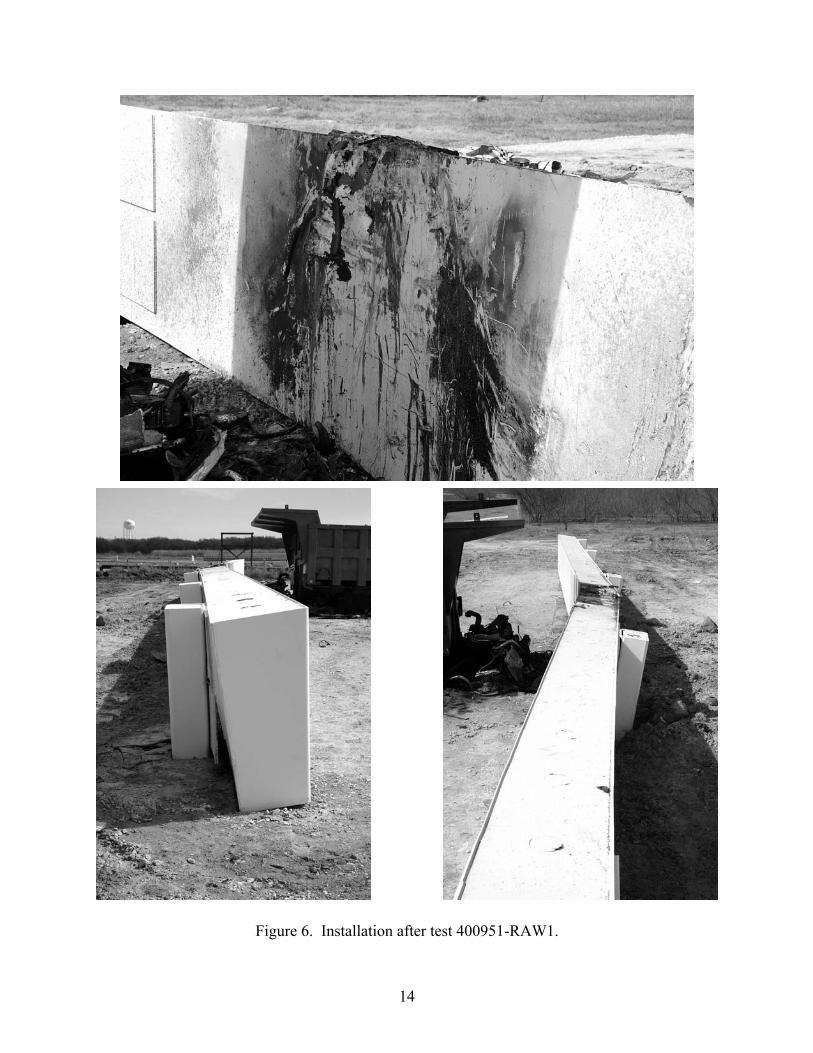
Figure 6. Installation after test 400951-RAW1.
14

Figure 6. Installation after test 400951-RAW1 (continued).
15

Table 2. Physical damage to the wall. Post Damage to Welds 1 Bottom plate detached from box on all right side, all bottom, all left side, and top
(5 inches to the right of post and 3 inches to the left of post) Bottom plate detached from post at top and bottom
2 Bottom plate detached from box on all bottom, right side (11 inches up from bottom), and left side (3 inches up from bottom)
3 No damage to any welds 4 Top plate detached from post on top (3 inches to right of post) 5 Bottom plate detached from box on bottom (12 inches to left of post) 6 Bottom plate detached from box on all bottom, all right side, and all left side 7 Bottom plate detached from box on all bottom, all right side, and all left side
Bottom plate detached from post at top Top plate detached from post at bottom
Post Damage to Posts 3 Front corners cracked, 2½ inches long on right, 1¼ inches long on left 4 Crack in front left top of post 2½ inches long
Post Deflection Left end Forward ¾ inch 1 Forward 2¼ inches, Up 1 inch, ½ inch residual on back 2 Back 5 inches, Up 1½ inches, At least 3½ inches residual on back 3 Back 17 inches, Up 2 inches, 10 inches residual on back 4 Back 15 inches, Up 2¼ inches, 9 inches residual on back 5 Back 6 inches, Up 1¼ inches 6 Forward 1½ inches, Up ¾ inch 7 Up ½ inch Right end Forward 5 inches Grout broken on back side of wall at Posts 1 through 6
16

Table 3. Post and wall deflections. Before test, stakes (4) placed 20 ft behind wall [or 18 ft - 11 inches behind posts (12 inch post + 1 inch plate)] After test, string line run between stakes and measurements taken every 5 ft Left end 20 ft - 7½ inches Post 1 18 ft - 10½ inches 20 ft - 1⅜ inches 19 ft - 8¼ inches Post 2 18 ft - 3½ inches 19 ft - 4 inches 19 ft - ¼ inch 18 ft - 9 inches Post 3 17 ft - 4¾ inches 18 ft - 2 inches Impact 18 ft - ¼ inch 18 ft - 3¾ inches Post 4 17 ft - 4½ inches 18 ft - 10½ inches 19 ft - 2 inches 19 ft - 4½ inches Post 5 18 ft - 4 inches 19 ft - 10 inches 19 ft - 10½ inches 19 ft - 11½ inches Post 6 18 ft - 9 inches 20 ft - 1¾ inches 20 ft - 3¾ inches Post 7 19 ft - ¼ inch Right end 20 ft - 5½ inches
After test, measurements were taken every 5 ft to determine how far out of plumb the back of the wall was Left end 7 inches Post 1 1¼ inches 6⅝ inches 6½ inches Post 2 4¼ inches 6½ inches 6½ inches 6⅜ inches Post 3 6 inches 6¾ inches Impact 6⅝ inches 6½ inches Post 4 6¼ inches 6 inches 5¾ inches 5 inches Post 5 3 inches 4⅛ inches 4¼ inches 4¼ inches Post 6 1⅛ inches 4¼ inches 4¼ inches Post 7 Level Right end 4¼ inches
17

18
Adler Wall Deflections
-10
-5
0
5
10
15
20
25
30
35
0 20 40 60 80 100 120
Feet
Inch
es
Base of Wall
Top of Wall
Post 2
Post 1
Post 3 Post 4
Post 5Post 6
Post 7
Impact
Figure 7. Wall deflections after test 400951-RAW1.

Figure 8. Vehicle after test 400951-RAW1.
19

Before test
After test
Figure 9. Interior of vehicle for test 400951-RAW1.
20

0.000 s
0.099 s
0.298 s
0.596 s
1
7
6
5
2
3
4 Piece of hood
90.2°
3'-8 "
5'-1"56'
24'-6"
Windshield
Drawings are proprietary property of RSA and have been removed per sponsor’s request.
21
General Information Test Agency............................... Test No. .................................... Date ........................................... Test Article Type........................................... Name ......................................... Installation Length (ft) ................ Material or Key Elements .......... Soil/Foundation Type .................
Texas Transportation Institute 400951-RAW1 02/17/04 Security Wall Adler Anti-Ram Wall™ 120.0 Pre-Fabricated Steel Boxes And Piers Filled With Concrete Concrete Footing
Test Vehicle Type .......................................... Designation ............................... Model......................................... Mass (lb) Curb ....................................... Test Inertial ............................ Gross Static............................ Impact Conditions Speed (mi/h) .............................. Angle (deg)................................ Exit Conditions Speed (mi/h) .............................. Angle (deg)................................
Production 8000S 1986 Ford L8000 29,320 65,040 65,040 51.4 90.2 Stopped N/A
Occupant Risk Values Impact Velocity (ft/s) Longitudinal........................... Lateral ................................... Ridedown Accelerations (g’s) Longitudinal........................... Lateral ................................... Max. 0.050-s Average (g’s) Longitudinal........................... Lateral ................................... Vertical .................................. Test Article Deflections (ft) Dynamic ................................... Permanent................................ Working Width ..........................
35.7 2.0 -13.0 1.1 -13.1 0.9 1.5 3.45 1.98 7.38
Figure 10. Summary of results for test 400951-RAW1.


SUMMARY AND CONCLUSIONS ASSESSMENT OF TEST RESULTS Target impact speed was 50 mph +3/-2 mph, and the actual impact speed was 51.2 mph. The 1986 Ford L8000 tandem axle, single-unit truck impacted the Adler Anti-Ram Wall™ at 90.2 degrees, 9.5 ft to the left of post 4. The Adler Anti-Ram Wall™ brought the vehicle to a complete stop with no penetration of the vehicle (other than the hood and windshield). The maximum deflection of the wall was 23.75 inches at the left end. It should be noted that this test is recognized to be atypical in nature. Modifications to the truck (rigidly attaching the cargo to the bed and welding the bed to the truck frame) were intended to tie all of the mass of the truck frame and cargo together to deliver the maximum energy into the vehicle barrier. Previous testing of similarly sized trucks with much less weight and at slower speeds into a rigid vehicle barrier has shown that the cargo and bed of the truck shear through the cab and slide over the vehicle barrier penetrating the perimeter by 100-140 ft. This test was designed to maximize energy into the barrier. Realistic threat vehicles may shear on impact and have large portions of the vehicle penetrating a significant distance into the protected area. CONCLUSIONS The Adler Anti-Ram Wall™ met the criteria for a Class II barrier (see table 1) due to the 23.75-inch barrier deflection.
23


REFERENCES 1. H. E. Ross, Jr., D. L. Sicking, R. A. Zimmer and J. D. Michie, Recommended Procedures
for the Safety Performance Evaluation of Highway Features, National Cooperative Highway Research Program Report 350, Transportation Research Board, National Research Council, Washington, D.C., 1993.
25


APPENDIX A. CRASH TEST PROCEDURES AND DATA ANALYSIS The crash test and data analysis procedures were in accordance with guidelines presented in NCHRP Report 350. Brief descriptions of these procedures are presented as follows. ELECTRONIC INSTRUMENTATION AND DATA PROCESSING The test vehicle was instrumented with a triaxial accelerometer near the vehicle center of gravity (c.g.) to measure longitudinal, lateral, and vertical acceleration levels; and a backup triaxial accelerometer over the rear axle of the vehicle to measure longitudinal, lateral, and vertical acceleration levels. These accelerometers were ENDEVCO Model 2262CA, piezoresistive accelerometers with a +100 g range. The accelerometers are strain gage type with a linear millivolt output proportional to acceleration. Angular rate transducers are solid state, gas flow units designed for high-“g” service. Signal conditioners and amplifiers in the test vehicle increase the low-level signals to a +2.5 volt maximum level. The signal conditioners also provide the capability of an R-cal (resistive calibration) or shunt calibration for the accelerometers and a precision voltage calibration for the rate transducers. The electronic signals from the accelerometers and rate transducers are transmitted to a base station by means of a 15-channel, constant-bandwidth, Inter-Range Instrumentation Group (IRIG), FM/FM telemetry link for recording on magnetic tape and for display on a real-time strip chart. Calibration signals from the test vehicle are recorded before the test and immediately afterwards. A crystal-controlled time reference signal is simultaneously recorded with the data. Wooden dowels actuate pressure-sensitive switches on the bumper of the impacting vehicle prior to impact by wooden dowels to indicate the elapsed time over a known distance to provide a measurement of impact velocity. The initial contact also produces an “event” mark on the data record to establish the instant of contact with the installation. The multiplex of data channels, transmitted on one radio frequency, is received and demultiplexed onto separate tracks of a 28-track, IRIG tape recorder. After the test, the data are played back from the tape machine and digitized. A proprietary software program (WinDigit) converts the analog data from each transducer into engineering units using the R-cal and pre-zero values at 10,000 samples per second, per channel. WinDigit also provides Society of Automotive Engineers (SAE J211) class 180 phaseless digital filtering and vehicle impact velocity. All accelerometers are calibrated annually according to SAE J211 4.6.1 by means of an ENDEVCO 2901, precision primary vibration standard. This device and its support instruments are returned to the factory annually for a National Institute of Standards Technology (NIST) traceable calibration. The subsystems of each data channel are also evaluated annually, using instruments with current NIST traceability, and the results are factored into the accuracy of the total data channel, per SAE J211. Calibrations and evaluations are made any time data are suspect.
27

The Test Risk Assessment Program (TRAP) uses the data from WinDigit to compute occupant/compartment impact velocities, time of occupant/compartment impact after vehicle impact, and the highest 10-millisecond (ms) average ridedown acceleration. WinDigit calculates change in vehicle velocity at the end of a given impulse period. In addition, maximum average accelerations over 50-ms intervals in each of the three directions are computed. For reporting purposes, the data from the vehicle-mounted accelerometers are filtered with a 60-Hz digital filter, and acceleration versus time curves for the longitudinal, lateral, and vertical directions are plotted using TRAP. PHOTOGRAPHIC INSTRUMENTATION AND DATA PROCESSING Photographic coverage of the test included three high-speed cameras: one overhead with a field of view perpendicular to the ground and directly over the impact point; one placed behind the installation at an angle; and a third placed to have a field of view parallel to and aligned with the installation at the downstream end. A flashbulb activated by pressure-sensitive tape switches was positioned on the impacting vehicle to indicate the instant of contact with the installation and was visible from each camera. The films from these high-speed cameras were analyzed on a computer-linked motion analyzer to observe phenomena occurring during the collision and to obtain time-event, displacement, and angular data. A BetaCam, a VHS-format video camera and recorder, and still cameras recorded and documented conditions of the test vehicle and installation before and after the test. TEST VEHICLE PROPULSION AND GUIDANCE The test vehicle was directed into the test installation using a remove control guidance system. Immediately prior to impact, the fuel to the engine was shut off and the test vehicle steering was released to be free-wheeling and unrestrained. The vehicle remained free-wheeling, i.e., no steering or braking inputs, until the vehicle cleared the immediate area of the test site.
28

APPENDIX B. TEST VEHICLE PROPERTIES AND INFORMATION
DATE: 02-17-2004 TEST NO.: 400951-RAW1 ODOMETER: 035077 YEAR: 1986 MAKE: Ford MODEL: L8000 TIRE SIZE: 385/65R225 VIN NO.: 1FD2W80U4GVA56975 GEOMETRY (in) A 96 D 119.5 G 150.2 K 30 N 1.0 Q 71.0 T 41 B 26 E 54.0 H ----- L 56 O 16.5 R 41.5 X 56 C 187 F 297.0 J 73.0 M 33 P 81.0 S 23.5
MASS (lb) CURB TEST INERTIAL
M1 9730 12650 M2 9970 26240 M3 9620 26150
MTotal 29320 65040
Figure 11. Vehicle properties for test 400951-RAW1.
29

h

APPENDIX C. SEQUENTIAL PHOTOGRAPHS
0.000 s
0.050 s
0.099 s
0.199 s
Figure 12. Sequential photographs for test 400951-RAW1 (overhead and frontal views).
31

0.298 s
0.447 s
0.596 s
0.999 s
Figure 12. Sequential photographs for test 400951-RAW1 (overhead and frontal views) (continued).
32

0.000 s 0.298 s
0.050 s 0.447 s
0.099 s 0.596 s
0.199 s 0.999 s
Figure 13. Sequential photographs for test 400951-RAW1 (perpendicular view).
33


35
APPENDIX D. VEHICLE ACCELERATIONS
APPE
ND
IX D
. VE
HIC
LE
AC
CE
LE
RA
TIO
NS
X Acceleration at CG
0 0.1 0.2 0.3 0.4 0.5 0.6 0.7 0.8 0.9 1.0-20
-10
0
10
20
Time (sec)
Long
itudi
nal A
ccel
erat
ion
(g's
)
Test Number: 400951-RAW1Test Article: Adler Anti-Ram WallTest Vehicle: 1986 Ford L8000Inertial Mass: 29510 kgGross Mass: 29510 kgImpact Speed: 82.6 km/hImpact Angle: 90 degrees
SAE Class 60 Filter
Figure 14. Vehicle longitudinal accelerometer trace for test 400951-RAW1 (accelerometer located at center of gravity).

36
Y Acceleration at CG
0 0.1 0.2 0.3 0.4 0.5 0.6 0.7 0.8 0.9 1.0-5
-4
-3
-2
-1
0
1
2
3
4
5
Time (sec)
Late
ral A
ccel
erat
ion
(g's
)
Test Number: 400951-RAW1Test Article: Adler Anti-Ram WallTest Vehicle: 1986 Ford L8000Inertial Mass: 29510 kgGross Mass: 29510 kgImpact Speed: 82.6 km/hImpact Angle: 90 degrees
SAE Class 60 Filter
Figure 15. Vehicle lateral accelerometer trace for test 400951-RAW1 (accelerometer located at center of gravity).

37
Z Acceleration at CG
0 0.1 0.2 0.3 0.4 0.5 0.6 0.7 0.8 0.9 1.0-5
-4
-3
-2
-1
0
1
2
3
4
5
Time (sec)
Vert
ical
Acc
eler
atio
n (g
's)
Test Number: 400951-RAW1Test Article: Adler Anti-Ram WallTest Vehicle: 1986 Ford L8000Inertial Mass: 29510 kgGross Mass: 29510 kgImpact Speed: 82.6 km/hImpact Angle: 90 degrees
SAE Class 60 Filter
Figure 16. Vehicle vertical accelerometer trace for test 400951-RAW1 (accelerometer located at center of gravity).

38
X Acceleration Over Rear Axle
0 0.1 0.2 0.3 0.4 0.5 0.6 0.7 0.8 0.9 1.0-20
-10
0
10
20
Time (sec)
Long
itudi
nal A
ccel
erat
ion
(g's
)
Test Number: 400951-RAW1Test Article: Adler Anti-Ram WallTest Vehicle: 1986 Ford L8000Inertial Mass: 29510 kgGross Mass: 29510 kgImpact Speed: 82.6 km/hImpact Angle: 90 degrees
SAE Class 60 Filter
Figure 17. Vehicle longitudinal accelerometer trace for test 400951-RAW1 (accelerometer located over rear axle).

39
Y Acceleration Over Rear Axle
0 0.1 0.2 0.3 0.4 0.5 0.6 0.7 0.8 0.9 1.0-5
-4
-3
-2
-1
0
1
2
3
4
5
Time (sec)
Late
ral A
ccel
erat
ion
(g's
)
Test Number: 400951-RAW1Test Article: Adler Anti-Ram WallTest Vehicle: 1986 Ford L8000Inertial Mass: 29510 kgGross Mass: 29510 kgImpact Speed: 82.6 km/hImpact Angle: 90 degrees
SAE Class 60 Filter
Figure 18. Vehicle lateral accelerometer trace for test 400951-RAW1 (accelerometer located over rear axle).

40
Z Acceleration Over Rear Axle
0 0.1 0.2 0.3 0.4 0.5 0.6 0.7 0.8 0.9 1.0-15
-10
-5
0
5
10
15
Time (sec)
Vert
ical
Acc
eler
atio
n (g
's)
Test Number: 400951-RAW1Test Article: Adler Anti-Ram WallTest Vehicle: 1986 Ford L8000Inertial Mass: 29510 kgGross Mass: 29510 kgImpact Speed: 82.6 km/hImpact Angle: 90 degrees
SAE Class 60 Filter
Figure 19. Vehicle vertical accelerometer trace for test 400951-RAW1 (accelerometer located over rear axle).


![Pensacola Journal. (Pensacola, Florida) 1907-09-08 [p ].ufdcimages.uflib.ufl.edu/UF/00/07/59/11/00951/00594.pdf · 2009-03-27 · speeches Hundred digging PortoRico manages Pound](https://static.fdocuments.in/doc/165x107/5e4e198650f9f204b34b55dc/pensacola-journal-pensacola-florida-1907-09-08-p-2009-03-27-speeches-hundred.jpg)
