New superior assembly technologies for modules with highest
4
New superior assembly technologies for modules with highest power densities Dr. Roland Ott, Marco Bäßler, Roman Tschirbs, Dirk Siepe, Infineon Technologies AG, Germany Abstract Power module development is striving for higher power densities, not only in new but also in already established packages. Two main challenges for such kinds of upgrades are to meet the increased requirements towards ampacity and heat dissipation. These new requirements may enforce adjustments in the utilized packaging technologies to overcome the given package limitations. The current article investigates the challenges of increased power densities in existing module packages and how they can be mastered. 1. Introduction The continuous trend of IGBT chip optimization [1], [2] enables IGBT power module development to increase the power density in their packages from IGBT generation to IGBT generation. For example, the nominal current rating of Infin- eon 62mm half-bridge modules was increased continuously over the different IGBT generations from IGBT 1 st generation (Inom = 150A) to IGBT 4 th generation (Inom = 450A) by a factor of three (see Fig. 1). This increased power density is doubtlessly be- neficial especially for the design of more and more compact inverters and therefore more than welcomed by the IGBT power module market. In particular, there is a strong demand for in- creased power densities in already well estab- lished IGBT power module packages, as it offers the inverter designers the opportunity not only to integrate such packages into newly developed in- verters, but also to upgrade existing inverter designs to higher output powers without changing the mechanical set-up. Especially this fact makes it a very fast, cheap and therefore extremely at- tractive opportunity. However, handling of the increased power densit- ies in a given module package might be limited by several boundary conditions, as inverter cool- ing conditions and maximum system temperat- ures. But also from the IGBT module’s point of view, measures might have to be taken to assure that the current rating offered by the implemented silicone dies can be fully utilized in the real ap- plication. Fig. 1. Steadily increasing power density at the example of Infineon’s 62mm half-bridge IGBT module: For each IGBT generation, the maximum realized current rating is given. Most probably, the two most relevant parameters of a given IGBT power module package will be • the ampacity / conductivity and • the thermal resistivity. A detailed analysis of the influence of ampacity and thermal resistivity of IGBT module packages on the utilization of increased power densities will be carried out in the next chapter.
Transcript of New superior assembly technologies for modules with highest
New superior assembly technologies for modules with highest power densitiesDr. Roland Ott, Marco Bäßler, Roman Tschirbs, Dirk Siepe, Infineon Technologies AG, Germany
Abstract
Power module development is striving for higher power densities, not only in new but also in already established packages. Two main challenges for such kinds of upgrades are to meet the increased requirements towards ampacity and heat dissipation. These new requirements may enforce adjustments in the utilized packaging technologies to overcome the given package limitations. The current article investigates the challenges of increased power densities in existing module packages and how they can be mastered.
1. IntroductionThe continuous trend of IGBT chip optimization [1], [2] enables IGBT power module development to increase the power density in their packages from IGBT generation to IGBT generation. For example, the nominal current rating of Infin-eon 62mm half-bridge modules was increased continuously over the different IGBT generations from IGBT 1st generation (Inom = 150A) to IGBT 4th
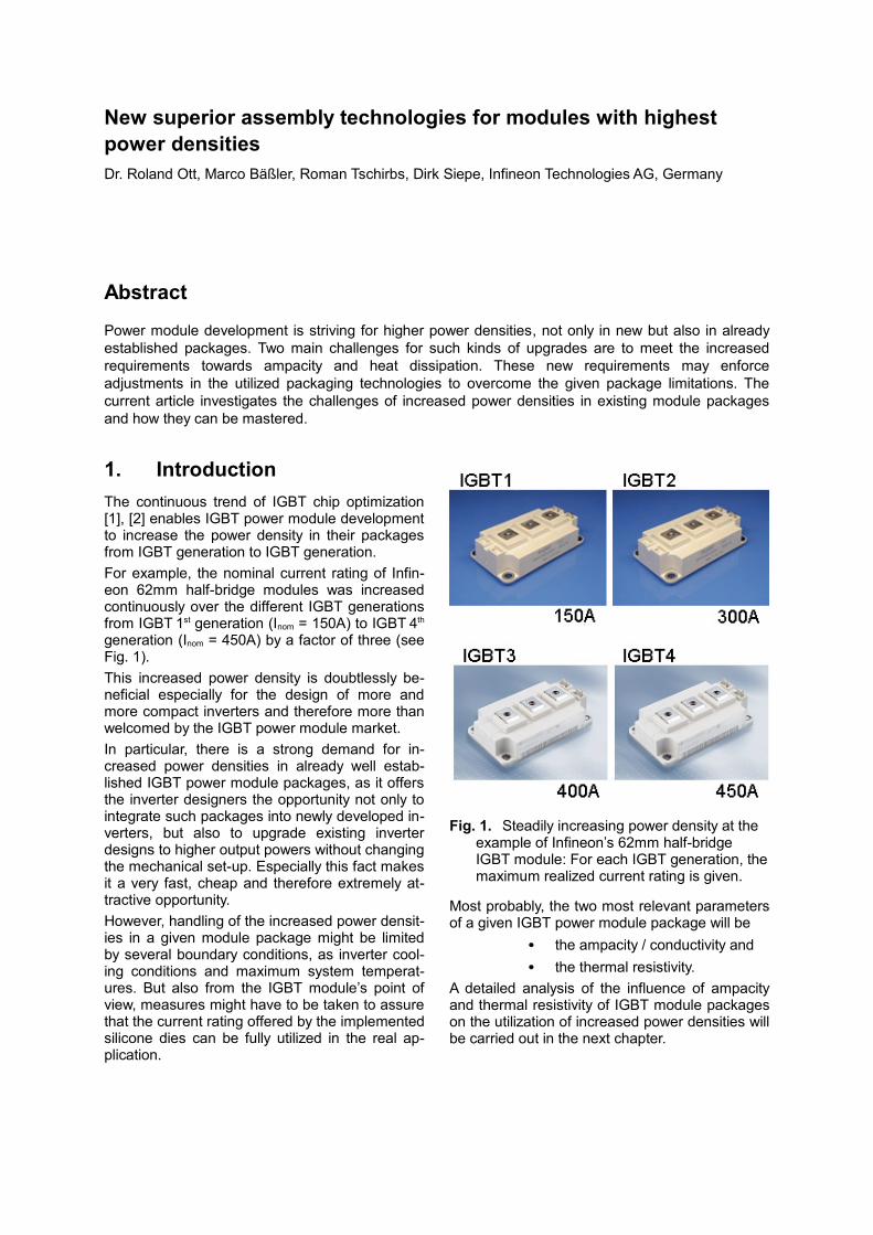
generation (Inom = 450A) by a factor of three (see Fig. 1).This increased power density is doubtlessly be-neficial especially for the design of more and more compact inverters and therefore more than welcomed by the IGBT power module market. In particular, there is a strong demand for in-creased power densities in already well estab-lished IGBT power module packages, as it offers the inverter designers the opportunity not only to integrate such packages into newly developed in-verters, but also to upgrade existing inverter designs to higher output powers without changing the mechanical set-up. Especially this fact makes it a very fast, cheap and therefore extremely at-tractive opportunity.However, handling of the increased power densit-ies in a given module package might be limited by several boundary conditions, as inverter cool-ing conditions and maximum system temperat-ures. But also from the IGBT module’s point of view, measures might have to be taken to assure that the current rating offered by the implemented silicone dies can be fully utilized in the real ap-plication.
Fig. 1. Steadily increasing power density at the example of Infineon’s 62mm half-bridge IGBT module: For each IGBT generation, the maximum realized current rating is given.
Most probably, the two most relevant parameters of a given IGBT power module package will be
• the ampacity / conductivity and• the thermal resistivity.
A detailed analysis of the influence of ampacity and thermal resistivity of IGBT module packages on the utilization of increased power densities will be carried out in the next chapter.
2. Enabling higher power densities
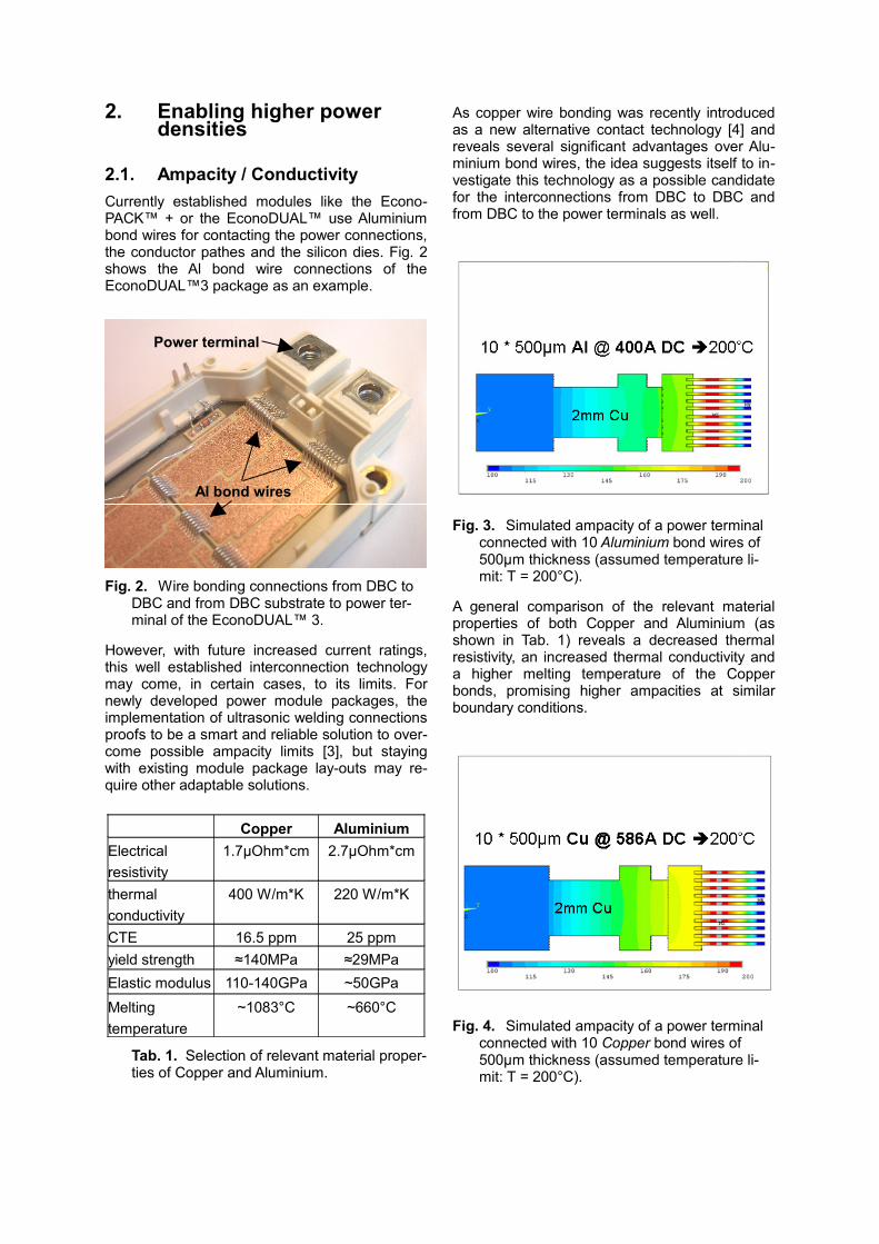
2.1. Ampacity / ConductivityCurrently established modules like the Econo-PACK™ + or the EconoDUAL™ use Aluminium bond wires for contacting the power connections, the conductor pathes and the silicon dies. Fig. 2 shows the Al bond wire connections of the EconoDUAL™3 package as an example.
Fig. 2. Wire bonding connections from DBC to DBC and from DBC substrate to power ter-minal of the EconoDUAL™ 3.
However, with future increased current ratings, this well established interconnection technology may come, in certain cases, to its limits. For newly developed power module packages, the implementation of ultrasonic welding connections proofs to be a smart and reliable solution to over-come possible ampacity limits [3], but staying with existing module package lay-outs may re-quire other adaptable solutions.
Copper AluminiumElectrical resistivity
1.7µOhm*cm 2.7µOhm*cm
thermal conductivity
400 W/m*K 220 W/m*K
CTE 16.5 ppm 25 ppmyield strength ≈140MPa ≈29MPaElastic modulus 110-140GPa ~50GPaMelting temperature
~1083°C ~660°C
Tab. 1. Selection of relevant material proper-ties of Copper and Aluminium.
As copper wire bonding was recently introduced as a new alternative contact technology [4] and reveals several significant advantages over Alu-minium bond wires, the idea suggests itself to in-vestigate this technology as a possible candidate for the interconnections from DBC to DBC and from DBC to the power terminals as well.
Fig. 3. Simulated ampacity of a power terminal connected with 10 Aluminium bond wires of 500µm thickness (assumed temperature li-mit: T = 200°C).
A general comparison of the relevant material properties of both Copper and Aluminium (as shown in Tab. 1) reveals a decreased thermal resistivity, an increased thermal conductivity and a higher melting temperature of the Copper bonds, promising higher ampacities at similar boundary conditions.
Fig. 4. Simulated ampacity of a power terminal connected with 10 Copper bond wires of 500µm thickness (assumed temperature li-mit: T = 200°C).
Power terminal
Al bond wires
Numerical simulations (Fig. 3 and Fig. 4) illus-trate the electro-thermal advantages of the cop-per bond wires over the Aluminium bonds in more detail: At similar boundary conditions, the ampacity of a chosen standard set-up with 10 bond wires of each 500µm thickness was increased by a factor of ~1.5 from 400A to almost 600A dc collector current. This result makes copper bond wires an ideal candidate for the substitution of Aluminium bond wires in existing IGBT module packages, whenever an increased ampacity is required.
2.2. Thermal resistivityIncreasing the power density in a given package might lead to a higher power dissipation density, being not only a challenge for the cooling system of the inverter, but also for all thermal interfaces inside the module.
Fig. 5. Heat flow and spreading in a state-of-the-art IGBT power module with base plate. The DBC parts are highlighted.
In general, the thermal resistivity Rth of a specific material is determined by the thickness (s), the thermally active area (A) and the thermal con-ductivity λ:
λ⋅=AsRth .
Following this equation, it can be concluded that a reduction of the thermal resistance of a layer inside a power module system can be achieved by
• reducing its thickness s,• increasing its thermal conductiv-
ity λ or• increasing its thermally active
area A by improved heat spread-ing in previous layers.
Fig. 5 shows the schematic of heat flow and spreading in a state-of-the-art IGBT power mod-
ule with base plate. At a given set-up (module with or without base plate, thermal interface ma-terial, cooler), the layers to be particularly optim-ized are the DBC copper and DBC ceramic lay-ers, e.g. by
• increasing the DBC conducting layer thickness for improved conductivity and heat spreading,
• increasing the thermal conductiv-ity λ of the DBC ceramic layer or
• reducing the DBC ceramic layer thickness.
The decisions of the specifically appropriate measures have to be drawn from case to case. Furthermore, the technical feasibility as well as the cost of all possible solutions has to be taken into account.
3. Transfer to a real product: EconoDUAL™ 3
Based on the previous considerations, the devel-opment of a new EconoDUAL™ 3 module has been started. The development target was not only to achieve a nominal current rating of 600A in the 1200V blocking voltage class by the imple-mentation of the latest IGBT 4th generation dies, but also to provide a real increase of the achiev-able RMS output current of the inverter, com-pared to the already existing 450A EconoDUAL™ 3.
Fig. 6. Newly developed 1200V EconoDUAL™ 3 with 600A nominal current, utilizing copper bond wires and optimized DBC.
For the realization of this target, copper bond wires were implemented for the interconnections of the copper conductor paths on the DBCs as
well as for the connections to the power terminals (see Fig. 6).Furthermore, the DBC was thermally optimized by a combination of several appropriate meas-ures as described in chapter 2.2, improving heat spreading and thermal resistance of the pack-age.
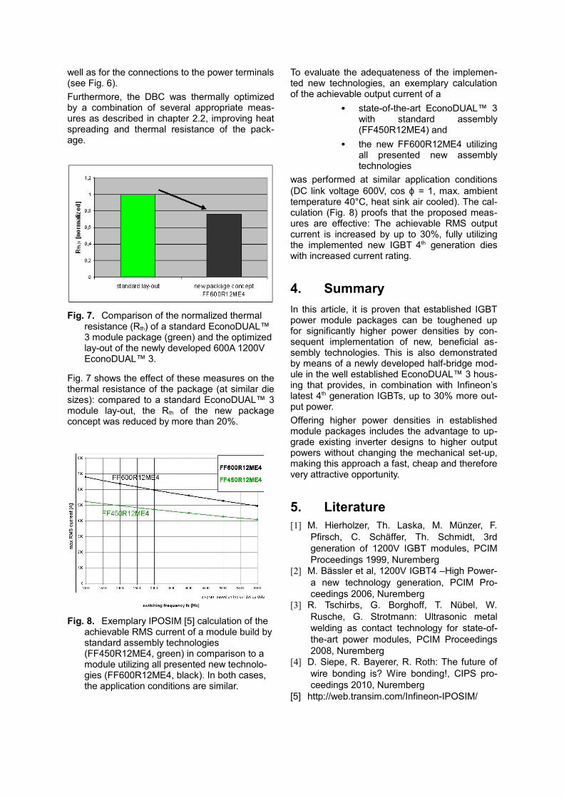
Fig. 7. Comparison of the normalized thermal resistance (Rth) of a standard EconoDUAL™ 3 module package (green) and the optimized lay-out of the newly developed 600A 1200V EconoDUAL™ 3.
Fig. 7 shows the effect of these measures on the thermal resistance of the package (at similar die sizes): compared to a standard EconoDUAL™ 3 module lay-out, the Rth of the new package concept was reduced by more than 20%.
Fig. 8. Exemplary IPOSIM [5] calculation of the achievable RMS current of a module build by standard assembly technologies (FF450R12ME4, green) in comparison to a module utilizing all presented new technolo-gies (FF600R12ME4, black). In both cases, the application conditions are similar.
To evaluate the adequateness of the implemen-ted new technologies, an exemplary calculation of the achievable output current of a
• state-of-the-art EconoDUAL™ 3 with standard assembly (FF450R12ME4) and
• the new FF600R12ME4 utilizing all presented new assembly technologies
was performed at similar application conditions (DC link voltage 600V, cos ϕ = 1, max. ambient temperature 40°C, heat sink air cooled). The cal-culation (Fig. 8) proofs that the proposed meas-ures are effective: The achievable RMS output current is increased by up to 30%, fully utilizing the implemented new IGBT 4th generation dies with increased current rating.
4. SummaryIn this article, it is proven that established IGBT power module packages can be toughened up for significantly higher power densities by con-sequent implementation of new, beneficial as-sembly technologies. This is also demonstrated by means of a newly developed half-bridge mod-ule in the well established EconoDUAL™ 3 hous-ing that provides, in combination with Infineon’s latest 4th generation IGBTs, up to 30% more out-put power. Offering higher power densities in established module packages includes the advantage to up-grade existing inverter designs to higher output powers without changing the mechanical set-up, making this approach a fast, cheap and therefore very attractive opportunity.
5. Literature[1] M. Hierholzer, Th. Laska, M. Münzer, F.
Pfirsch, C. Schäffer, Th. Schmidt, 3rd generation of 1200V IGBT modules, PCIM Proceedings 1999, Nuremberg
[2] M. Bässler et al, 1200V IGBT4 –High Power- a new technology generation, PCIM Pro-ceedings 2006, Nuremberg
[3] R. Tschirbs, G. Borghoff, T. Nübel, W. Rusche, G. Strotmann: Ultrasonic metal welding as contact technology for state-of-the-art power modules, PCIM Proceedings 2008, Nuremberg
[4] D. Siepe, R. Bayerer, R. Roth: The future of wire bonding is? Wire bonding!, CIPS pro-ceedings 2010, Nuremberg
[5] http://web.transim.com/Infineon-IPOSIM/


![RELAXED HIGHEST-WEIGHT MODULES III: CHARACTER FORMULAE · 2020-03-24 · arXiv:2003.10148v1 [math.RT] 23 Mar 2020 RELAXED HIGHEST-WEIGHT MODULES III: CHARACTER FORMULAE KAZUYA KAWASETSU](https://static.fdocuments.in/doc/165x107/5f88fd3666ad825972782331/relaxed-highest-weight-modules-iii-character-formulae-2020-03-24-arxiv200310148v1.jpg)