NEW STEEL THREADED INSERTS - PRECAST CONNECTION ...the ReidBar™ Steel Threaded Insert, with a...
10
NEW STEEL THREADED INSERTS - PRECAST CONNECTION APPLICATIONS TESTING TO NZS 3101 A3 EMANUELE NACCINI ramsetreid SUMMARY In New Zealand, the use and design of mechanical anchors and mechanical connections with reinforcing bars in concrete structures is covered by the Verification Method (B1/VM1) [9] . This document cites the Concrete Structures Standard NZS 3101:2006 [1] , which provides a method of complying with the NZ Building Code, a performance-based code system. NZS 3101 sets out the requirements and the conditions under which those components can be utilized. This paper will present a summary of the tests that have been conducted on a new product, the ReidBar™ Steel Threaded Insert, with a focus on how the anchors behave in concrete. INTRODUCTION Mechanical anchorage connections such as Threaded Inserts have been used by industry as a precast panel connection solution for over 20 years. In August 2017, new requirements and more stringent performance criteria were prescribed for mechanical connections when Amendment 3 of NZS 3101:2006 was introduced into the New Zealand market. As such, this has instigated New Zealand manufactures to develop new products and systems which are capable of meeting the new criteria. Recent studies on the performance of precast concrete panel-to-foundation connections, presented at past editions of the Concrete Conference and also published in the SESOC Journal, have demonstrated how a correct detail can positively influence the inelastic behaviour of the connection. Acknowledging this, the newly developed Steel Threaded Insert have been tested in full-scale set-ups aligned with these recent studies. The test program included a total amount of 147 inserts, installed on 24 concrete panels with various thicknesses and reinforcing configuration and was performed by an independent third- party NATA accredited laboratory (National Association of Testing Authorities, Australia). The results of the testing were assessed, statistically analysed and used to publish documentation demonstrating compliance to the new NZS 3101 performance criteria and incorporating the characteristic concrete capacity on cracked and uncracked concrete. PERFORMANCE REQUIREMENTS FROM NZS 3101 A3 In order to be compliant with NZS 3101 Amendment 3, a reinforcement mechanical anchorage, such as the Steel Threaded Insert, needs to meet the requirements shown in Table 1.
Transcript of NEW STEEL THREADED INSERTS - PRECAST CONNECTION ...the ReidBar™ Steel Threaded Insert, with a...

NEW STEEL THREADED INSERTS - PRECAST CONNECTION APPLICATIONS TESTING TO NZS 3101 A3
EMANUELE NACCINI
ramsetreid SUMMARY In New Zealand, the use and design of mechanical anchors and mechanical connections with reinforcing bars in concrete structures is covered by the Verification Method (B1/VM1) [9]. This document cites the Concrete Structures Standard NZS 3101:2006 [1], which provides a method of complying with the NZ Building Code, a performance-based code system. NZS 3101 sets out the requirements and the conditions under which those components can be utilized. This paper will present a summary of the tests that have been conducted on a new product, the ReidBar™ Steel Threaded Insert, with a focus on how the anchors behave in concrete. INTRODUCTION
Mechanical anchorage connections such as Threaded Inserts have been used by industry as a precast panel connection solution for over 20 years.
In August 2017, new requirements and more stringent performance criteria were prescribed for mechanical connections when Amendment 3 of NZS 3101:2006 was introduced into the New Zealand market. As such, this has instigated New Zealand manufactures to develop new products and systems which are capable of meeting the new criteria.
Recent studies on the performance of precast concrete panel-to-foundation connections, presented at past editions of the Concrete Conference and also published in the SESOC Journal, have demonstrated how a correct detail can positively influence the inelastic behaviour of the connection. Acknowledging this, the newly developed Steel Threaded Insert have been tested in full-scale set-ups aligned with these recent studies.
The test program included a total amount of 147 inserts, installed on 24 concrete panels with various thicknesses and reinforcing configuration and was performed by an independent third-party NATA accredited laboratory (National Association of Testing Authorities, Australia).
The results of the testing were assessed, statistically analysed and used to publish documentation demonstrating compliance to the new NZS 3101 performance criteria and incorporating the characteristic concrete capacity on cracked and uncracked concrete.
PERFORMANCE REQUIREMENTS FROM NZS 3101 A3 In order to be compliant with NZS 3101 Amendment 3, a reinforcement mechanical anchorage, such as the Steel Threaded Insert, needs to meet the requirements shown in Table 1.

Table 1. NZS 3101 A3 [1] – requirements for reinforcement mechanical anchorage
Section
8.6.11.1 “…shall be capable of developing the upper bound breaking strength of the reinforcing bar without damage to the concrete or overall deformation of the anchorage.” (From 8.6.11.2, this corresponds to 1.25 times the upper characteristic yield strength, which is 750MPa for 500E grade reinforcement).
“…the mode of failure of the anchored bar shall be by ductile yielding of the bar, with the bar developing its ultimate tensile strength at a location outside the mechanical anchorage and away from any zone of the bar affected by working (e.g. by cold forging).”
8.6.11.3 “…shall meet both the permanent extension and fatigue strength criteria of 8.7.5.2.” “…there shall be no thread stripping or evidence of significant distortion of the threads at the failure load of the bar.”
8.6.11.4 “…shall be proven by an appropriate test method to possess resistance to brittle fracture at the service temperatures at which they are intended for use.” “…appropriate testing of the processed bar end shall be applied to ensure that the potential of the brittle fracture is avoided.”
“Anchors manufactured from cast iron shall not be used”. 8.7.5.2 (a) “satisfy the requirements of 8.6.11 for mechanical anchors”
(b) “when tested in tension or compression, as appropriate, to the application, exhibit a change in length at a stress of 0.7fy in the bar, measured over the length of the coupler, of less than twice that of an equal length of un-spliced bar”
(c) “satisfy the requirements of 2.5.2.2 when used in situations where fatigue may develop”
8.9.1.3 “…to be used in members that are subject to seismic forces…mechanical splices and anchorages shall satisfy the cyclic load performance requirements specified by ISO 15835-1 and ISO 15835-2 as follows:
(a) “When tested in accordance with 5.6.2 of ISO 15835-2, the residual elongation after 4 cycles, u4, shall be less than 0.3mm, and after 8 cycles u8 shall be less than 0.6mm;”
(b) “Where high cycle fatigue is a consideration, the mechanical connection shall satisfy the requirements of 5.4 of ISO 15835-1. The testing shall comply with 5.5 of ISO 15835-2.”
Threaded Inserts aren’t commonly used in applications where high cycle fatigue may develop, and as such, 8.7.5.2 (c) and 8.9.1.3 (b) have not been considered. NZS 3101 doesn’t provide much guidance on how to demonstrate resistance to brittle fracture, therefore other relevant documents have been considered and more specifically the latest edition of the NZTA Bridge Manual, which suggests the Charpy V notch test at 0°C. Aside from the first one, all the requirements listed in Table 1 are either focused on the behavior of the mechanical connection between the reinforcing bar and the fitting or on the fitting itself. Third party laboratories have tested the new components against those requirements and a brief summary of the results is shown in table 2.
Table 2. Test results summary of Steel Threaded Inserts against NZS 3101 A3 requirements
Component Cl 8.7.5.2 (b) 0.7fy elong. & MoF*
Cl 8.9.1.3 (a) ISO 15835-2*
Cl 8.6.11.1 UTS>UBBS*
Cl 8.6.11.4 Charpy V notch @ 0°C**
N Aver. elong. [mm] #
Mode of Failure
N U4 [mm] U8 [mm] MoF N Min. [MPa]
N Average [Joules]
RB12TIS 5 0.21 (<0.42) All samples bar break
3 All <0.3 All <0.6 All samples bar break
5 807.1 ### 3 42
RBA16TIS 5 0.11 (<0.48) All samples bar break
3 All <0.3 All <0.6 All samples bar break
5 926.4 ### 3 38##
RB20TIS 5 0.19 (<0.55) All samples bar break
3 All <0.3 All <0.6 All samples bar break
5 930.3### 3 50##
* Tested by WSP-Opus ** Tested by X-Ray Laboratories ltd # Average elongation over component length, value in brackets represents the allowable displacement ## Sample size 2.5x10mm, number represents average equivalent energy absorbed for a 10x10mm specimen ### Tested with heat treated bars, for all the specimens bar break MoF (away from mech. conn.). The reported minimum value is not representative of actual strength of components as none of the tests succeed in breaking the components.
The components have demonstrated compliance with the performance requirements of NZS 3101, as shown in Table 2. However, the summary above doesn’t include testing in concrete, which is the main focus of this paper and will be covered in detail in the following sections.
PRECAST CONNECTION APPLICATIONS
One of the most common applications for reinforcing bar threaded inserts is in precast concrete panels for the wall-to-foundation connection. [7]

The inserts are used as dowels, cast inside the panels at the precast yard, and allow for easy and safe handling and transportation of the panels. Without protruding bars sticking out from the face of the finished elements, the impalement risk has been removed and the transportation cost heavily reduced. When the panels arrive on site and are placed, ready to be connected to the foundation, the starter bars are screwed into the inserts ready to be cast inside the foundation to consolidate the connection.
150mm thick panels - single layer of reinforcement – 12mm Steel Threaded Inserts A particular challenge is posed by singly reinforced panels, with a thickness typically varying between 120mm and 175mm, the most common being 150mm.
For these panels, several studies have demonstrated the importance of a correct detail to prevent premature inserts pull-out and allow the development of the expected load capacity in the connection. [2] [3] [4] [5] [6]
In an effort to improve the performance of the connection, a number of alternative detailing solutions have been proposed and tested by those studies [5], the most relevant being:
1. a deeper embedment depth, pushing the insert towards the far face of the panel 2. detailing a confined region around the joint 3. detailing of additional vertical reinforcement ”link bar”, at the joint in the near face of the
panel
The first solution, although simple and effective, reduces the concrete cover on the insert on the far face of the panel and might be a problem in terms of environmental exposure and durability.
The second solution is also effective, however, building the confinement reinforcing in the joint region of a 150mm thick panel poses some challenges.
The third solution provided good results and is also cost effective and easy to install, hence it was included in the testing program for the 150mm panels.
Figure 1. 150mm thick wall + RB12TIS - detail of connection to the foundation 200mm thick panels - double layer of reinforcement – 16mm Steel Threaded Inserts According to clause 11.3.3 of NZS 3101 A3 [1], 200mm is the maximum thickness for singly reinforced walls. However, it’s common (and good) practice to have two layers of reinforcement on 200mm thick concrete walls.

The second connection detail we have considered for the threaded inserts, which is suitable for bigger walls, is shown if Figure 2 and the wall is 200mm thick, reinforced with two layers of vertical and horizontal bars.
Figure 2. 200mm thick wall + RBA16TIS - detail of connection to the foundation
Figure 2 – Detail (a) is the standard configuration.
Figure 2 – Detail (b) is a variation to the standard configuration where the horizontal and vertical reinforcement are still the same but inverted to allow for 3 R8 S-Link ties per vertical bar in the connection area.
150mm thick panels - single layer of reinforcement – D12 L Starter Bars
As a reference, we have also tested 150mm thick panels with D12 L starter bars.
This is the most common detail, with 300E grade pull-out bars cast inside the panel, bent before transportation and re-bent on site to be cast inside the foundation.
As per NZS 3109 [8], only 300E grade bars can be bent and re-bent once without requiring heating to 750±75°C.
PHILOSOPHY
The main purpose of our study was to determine the behaviour of the new ReidBar Steel Threaded Inserts when installed in concrete with conditions as close as possible to the most common applications illustrated above.
Previous studies [2] [3] [4] [5] [6], have demonstrated that a critical condition for this type of connection is the out of plane bending moment on the panel, and more specifically the “opening” moment.
Top row of Threaded Inserts & “opening” bending moment
Under this condition, the top row of inserts is engaged in tension and at the same time, is working in a cracked concrete environment.
However, this can only happen if the reinforcement arrangement around the inserts is properly detailed and allows for a strut & tie model to develop inside the panel, without relying on the concrete tensile capacity.
Detail (a) – Standard Detail
Detail (b) – R8 S-Links variation
Of course, this isn’t a problem if the panel has a double layer of reinforcement, but for standard singly reinforced panels, there might be a missing/misplaced steel tie in the strut & tie model.
The “link bar” detail improvement, proposed and tested by Hogan et al.[5], overcomes this issue with an easy to install and simple solution which we have included in our 150mm thick panels for the testing program.
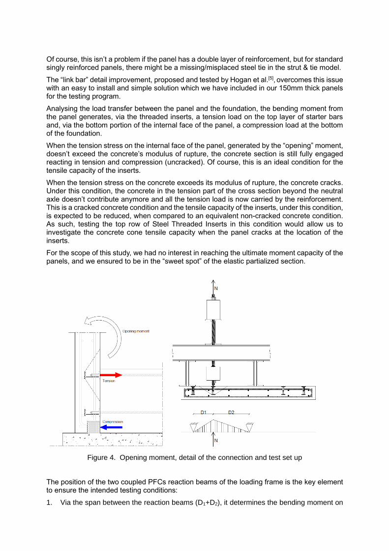
Analysing the load transfer between the panel and the foundation, the bending moment from the panel generates, via the threaded inserts, a tension load on the top layer of starter bars and, via the bottom portion of the internal face of the panel, a compression load at the bottom of the foundation.
When the tension stress on the internal face of the panel, generated by the “opening” moment, doesn’t exceed the concrete’s modulus of rupture, the concrete section is still fully engaged reacting in tension and compression (uncracked). Of course, this is an ideal condition for the tensile capacity of the inserts.
When the tension stress on the concrete exceeds its modulus of rupture, the concrete cracks. Under this condition, the concrete in the tension part of the cross section beyond the neutral axle doesn’t contribute anymore and all the tension load is now carried by the reinforcement. This is a cracked concrete condition and the tensile capacity of the inserts, under this condition, is expected to be reduced, when compared to an equivalent non-cracked concrete condition. As such, testing the top row of Steel Threaded Inserts in this condition would allow us to investigate the concrete cone tensile capacity when the panel cracks at the location of the inserts.
For the scope of this study, we had no interest in reaching the ultimate moment capacity of the panels, and we ensured to be in the “sweet spot” of the elastic partialized section.
Figure 4. Opening moment, detail of the connection and test set up
The position of the two coupled PFCs reaction beams of the loading frame is the key element to ensure the intended testing conditions:
1. Via the span between the reaction beams (D1+D2), it determines the bending moment on

the panel, which is generated by the tension load “N” applied on the inserts, as per equation (1) below
𝑀𝑚𝑎𝑥(𝑁) = 𝑁 ∙𝐷1∙𝐷2
(𝐷1+𝐷2) (1)
2. the ratio of the effective depth of the panel over the span (D1+D2) needs to be greater than 3.6 (ref. 9.3.1.6.1 of NZS 3101), this is required to avoid a “deep beam behavior” of the panel.
3. the reaction load transferred to the concrete, by the bottom flange of the PFCs, must not interfere with the concrete pull-out cone of the inserts, or at least be reflective, as much as possible, of the in-situ conditions (e.g. concrete strut).
One reaction beam was positioned over the edge of the panel (D1), and the maximum bending moment (a function of the tensile load N), was controlled by the position of the other reaction beam (D2). See Figure 4 for details.
Bottom row of Steel Threaded Inserts & “closing” bending moment
Under this condition, the bottom row of inserts is engaged in tension in a non-cracked concrete environment. However, depending on the geometric configuration, the capacity of the inserts might be affected by the interference of the bottom edge of the panel with the concrete pull-out cone.
Once again, the scope of the study was to determine the concrete cone tensile capacity of the inserts, under conditions closely matching a real application, and we had no interest in reaching the ultimate capacity of the panel.
The “clamping down beam” is positioned in a location where the panel subjected to a closing moment, receives the compression load from the foundation, as shown in Figure 5.
Figure 5. Closing moment, detail of the connection and test set up
In order to prevent the panels from reaching the ultimate moment capacity, it was decided to thicken the far face and provide additional reinforcement (for the tie of the resultant strut &tie model). Despite considerably changing the local behaviour of the panel, from cantilever beam to strut & tie, this modification doesn’t interfere with the behaviour and tensile strength of the bottom row of threaded inserts.

PANELS AND TESTS DESCRIPTION
The total width and length of every test panel was respectively 1m by 2m. The Specified concrete strength was 50MPa, however the test program worked around performing all the tests at a concrete strength of 40±2MPa.
Table 3. Panels description
Two tests have been performed on every panel, on the two symmetrically opposite sides, with the only exception of type 5C, which was just one isolated anchor in the middle of the 5A slabs.
In order to focus the test outcomes on the concrete cone behavior, and not on the mode of failure of the bar which has been investigated by other 3rd party tests, specifically heat treated ReidBars were outsourced and installed on the threaded inserts. The thermal treatment, developing a much higher tensile strength in the bar, allowed to pull the bars beyond the 750MPa threshold. The standard installation procedure of the bar in the Threaded Insert includes the use of Ramset™ EPCON™ C8 as a thread filler. However, since the epoxy is not required to develop the strength of the mechanical connection, to simplify and speed up the test program it was not utilized. Melbourne Testing Services took care of samples instrumentation and data logging with a calibrated load measuring device and two LDTs (linear displacement transducers). For two of the “opening moment” panels two CODs (crack open displacement) were also installed between steel plates adherent to the surface of the slab. See Figures 6 and 7 below showing pictures of the two test setups and closeup details of the LDTs and CODs.
Figure 6. Top row inserts, test set up and detail of LDT and COD on one side
Type Code
Thick. [mm]
Vert. Reinf. Horiz. Reinf. Inserts a1
[mm] a2
[mm] e
[mm] Other details
1A 300 HD12 @150c-c
HD10 @200c-c
RB12TIS 8mm NP
300 300 120 Vert.-link D10@each TI
1B 150 HD12 @150c-c
HD10 @200c-c
RB12TIS 8mm NP
300 300 120 Vert.-link D10@each TI
2A 300 HD12 @150c-c
HD10 @200c-c
D12 bent
300 300 120
2B 150 HD12 @150c-c
HD10 @200c-c
D12 bent
300 300 120
4A 300 HD16 @300c-c EF
HD16 @300c-c EF
RBA16TIS 8mm NP
350 300 180
4B 200 HD16 @300c-c EF
HD16 @300c-c EF
RBA16TIS 8mm NP
350 300 180
5A (Std)
300 HD16 @300c-c EF
HD16 @300c-c EF
RBA16TIS 8mm NP
350 300 180 S-links R10@200c-c
5A (Dp)
300 HD16 @300c-c EF
HD16 @300c-c EF
RBA16TIS 42mm NP
350 300 180 S-links R10@200c-c
5B 200 HD16 @300c-c EF
HD16 @300c-c EF
RBA16TIS 8mm NP
350 300 180 S-links R10@200c-c
5C 300 HD16 @300c-c EF
HD16 @300c-c EF
RBA16TIS 8mm NP
350 300 180 S-links R10@200c-c

Figure 7. bottom row inserts, test set up and detail of LDTs
For the top row of inserts (case B, opening moment) the position of the two reaction beams was determined by D1 and D2, as per Figure 4.
For the bottom row of inserts (case A, closing moment), the reaction beam was positioned with the outer edge of the bottom flange sitting over the centre of the top row of inserts, as per Figure 5.
RESULTS AND MODEL COMPARISON
Table 4 shows a summary of the test results, in terms of lower characteristic concrete capacity of the inserts and compares those numbers against the expected lower characteristic capacity from Chapter 17 of NZS 3101.
Table 4. Test results & model comparison
Type /
position N Anchors Concrete hef
[mm] D1
[mm] D2
[mm] D3
[mm] Mode of Failure a1
[mm] a2
[mm] e
[mm] Avg. UTL
[kN]*
Lwr. Char. [kN]**
Lwr. Char. Chp.17
NZS3101 [kN]
1A Bottom
3 2xRB12TIS 8mm NP
Non-crack. 40MPa
104 - - 420 3:Concr. Cone&edge
300 300 120 87.3 69.1 67.7#
1A Bottom
3 1xRB12TIS 8mm NP
Non-crack. 40MPa
104 - - 420 1:Bar break 2:load held
300 300 120 ## - -
1B Top
6 2xRB12TIS 8mm NP
Cracked 41.5MPa
104 200 410 - 6:Concr. Cone&edge 300 300 120 61.0 54.6 67.0#
2A Bottom
4 2 D12 bent Non-crack. 37.8MPa
- - 420 3:Concr. cone 1:Bar break
300 300 120 41.7 32.5 30.8***
2B Top
4 2 D12 bent Cracked 37.8MPa
200 410 - 4:Concr. cone
300 300 120 34.9 21.2 22.0***
4A Bottom
6 2xRBA16TIS 8mm NP
Non-crack. 40.2MPa
121 - - 480 2:Concr. Cone&edge 4:Long. Concr. Split
350 300 180 132.7
113.0 103.0#
4B Top
6 2xRBA16TIS 8mm NP
Cracked 40.2MPa
121 265 505 - 6:Concr. Cone&edge 350 300 180 79.3
71.8 82.9#
5A(Std) Bottom
3 2xRBA16TIS 8mm NP
Non-crack. 41.5MPa
121 - - 480 2:Concr. cone&edge 1:Concrete cone
350 300 180 129.5 121.3 104.6#
5A(Dp) Bottom
3 2xRBA16TIS 42mm NP
Non-crack. 41.5MPa
192 - - 480 2:Concr. Cone&edge 1:load held no failure
350 300 180 166.5 131.9 124.2#
5A(Dp) Bottom
3 2xRBA16TIS 42mm NP
Non-crack. 41.5MPa
192 - - 480 3 loads held with no failure
350 300 180 ##
- -
5B Top
6 2xRBA16TIS 8mm NP
Cracked 38.5MPa
121 265 505 - 5:Concr. Cone&edge 1:Concrete cone
350 300 180 82.7 74.1 81.1#
5C Middle
3 1xRBA16TIS 8mm NP
Non-crack. 38.5MPa
121 385 385 - 3:Concrete cone 350 300 180 146.9 128.1 103.3#
* Aver. Ultim. Tensile Load capacity per anchor from test results # Based on equations in NZS3101 Section 17.5.7.2, load capacity per anchor ** Lower Characteristic capacity per anchor from test results ## Test demonstrates that no concrete failure occurred and held at target load of 1.5xfsy *** Npn = 0.9 f’c eh do , eh = 4.5do [17.5.7.3 (b)], load cap. per anchor

Overall, there is an acceptable level of alignment between the test results and the NZS 3101 theoretical approach. However, it would appear that the NZS 3101 Chapter 17 provisions tend to underestimate the capacity in non-cracked concrete (-2 to -19%) and to overestimate the capacity in cracked concrete (9 to 23%). The latter one, being non-conservative, requires further consideration.
The above data addresses some of the findings from Hogan et al. [5] and, through testing, provides a more appropriate method, with respect to NZS 3101 anchor pull out equations, for design of Steel Threaded Insert connections, when failure might occur through the propagation of a flexural crack behind them.
The reinforcement and threaded insert layout of the test program within this document was aligned with the full-scale panel-to-foundation connection assemblies tested at the University of Auckland and reported in the paper published by Hogan et al [5]. Although the test set-up was much simpler, it has proven its capability of effectively recreating the Steel Threaded Inserts connections behaviour, particularly in the opening moment test which created cracked concrete conditions.
All opening moment tests were successful in developing the expected cracked concrete condition. This has been confirmed by:
- a visible flexural crack propagating perpendicularly from the centre of the inserts to the side edges of the panel
- a little “jump” recorded on the Load/Displacement curves at the formation of the flexural crack
- COD recordings consistent with the above signs
Figure 8. Top row inserts pull-out cone (left picture), Bottom row inserts concrete cone with edge effect (right picture).
CONCLUSIONS
The ReidBar Steel Threaded Inserts tested within this document have demonstrated compliance to NZS3101:2016 A3 through third party testing laboratories.
With respect to the behaviour in uncracked concrete, the Threaded Insert results provide better anchorage performance than the theoretical model for uncracked concrete in NZS3101 section 17. Having said this, we have also found that, although NZS3101 addresses the behaviour of anchorages in cracked concrete, the use of its concrete breakout equations, to design the opening moment connection, might lead to non-conservative results and strength assessment based upon tests, as per 17.4.4 of NZS 3101, might be more appropriate.
To address ductile failure mode of the connected elements, consideration should be given to the spacing, edge distance, concrete condition and concrete strength. The test results of the
Steel Threaded Inserts indicate that they can achieve the upper bound breaking strength of Gr500E ReidBar when anchored in concrete as shown in Table 4.
Furthermore, for precast panels, it is recommended to include reinforcement detail at the connection capable of protecting the joint integrity and force away any potential damage up into the panel. A link bar (shown in Figure 1) was included in the 150mm thick test panel set-up for this reason. This should be considered to maintain joint integrity and develop the nominal flexural capacity of the panel as per Hogan et al. [5]
(Published data on the new threaded inserts is reflective of the above test outcomes).
AKNOWLEDGEMENTS
ramsetreid™ Concrete Structures Laboratory and Melbourne Testing Services Ltd.
REFERENCES [1] Standards New Zealand (2017). “NZS 3101:2006, Amendment 3 – Concrete Structures Standard” [2] J. Burley, T. Faitotoa, P. Seifi, R. Lumantarna, R.S. Henry, J.M. Ingham, (2014). “Out-of-plane behavior of connections between precast concrete panels and their foundations”, The New Zealand Concrete Industry Conference 2014. [3] S.M. Burridge, M.P. Casey, M.L. Raby, H.D. Wright, L. Hogan, R.S. Henry, J.M. Ingham, (2015). “Improved detailing of precast concrete panel to foundation connections to withstand out-of-plane earthquake loads”, The New Zealand Concrete Industry Conference 2015.
[4] Henry R.,Lu Y., Seifi P., Zhang T., Hogan L., Ingham J., Elwood K.(2016), “Lightly
reinforced and precast concrete walls: recent research and design recommendations”, The
New Zealand Concrete Industry Conference 2016.
[5] Hogan, L.S., Henry, R.S., Ingham, J.M., (2017). “Recent testing and design recommendations for precast concrete panel-to-foundation connections”, The New Zealand Concrete Industry Conference 2017. [6] SESOC (2013). “Interim Design Guidance: Design of conventional structural systems
following the Canterbury earthquakes.” Version No.9, Structural Engineering Society of New
Zealand, New Zealand
[7] Seifi P., Henry R.S., & Ingham J.M. (2016). “Panel connection details in existing New
Zealand precast concrete buildings”. Bulletin of the New Zealand Society for Earthquake
Engineering. Vol 49 (2) 190-199
[8] Standards New Zealand (2004). “NZS 3109:1997, Amendment 2 – Concrete Construction”
[9] Ministry of Business, Innovation & Employment (2019). Verification Method B1/VM1